
FAR-2107 - Marine Electronics FURUNO - Free user manual and instructions
Find the device manual for free FAR-2107 FURUNO in PDF.


| Product Type | Marine Radar (Fishing Vessel Specifications) |
| Brand | Furuno |
| Model | FAR-2107 |
| Power Output | 50 kW / 60 kW models available |
| Display Type | Color LCD (assumed) |
| Trail Lengths | Normal (15s to continuous), 12h, 24h, 48h |
| Trail Colors | Fuchsia, maroon, red, purple, yellow, lime, green, olive, teal, cyan, blue, navy |
| Cursor Types | Crosshairs (small/large), Net cursor |
| Function Keys | F1, F2, F3 (programmable with 10 functions each), F4 macro key |
| Anchor Watch Alarm | Yes, settable range (6M to 20M) |
| Video Plotter Functions | Depth contour, marks (up to 20,000), track settings, GPS buoy |
| ARP/AIS Capability | Yes, with symbol color/size selection |
| Echo Display Areas | Circle, Wide, All |
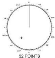
| Bearing Scale | 360° or 32 compass points |
| VRM/Cursor Units | NM, SM, km, kyd |
| Background Colors | Black-Green, Black-Red, Blue-Circle, Blue, Bright Blue |
| Echo Colors | Yellow, Green, White, Multi-color |
| Pop-up Guidance | Yes, for on-screen boxes |
| Safety Precautions | Follow standard marine radar safety guidelines (RF radiation, installation) |
| Maintenance | Refer to operator's manual for periodic checks; keep display clean |
Frequently Asked Questions - FAR-2107 FURUNO
User questions about FAR-2107 FURUNO
0 question about this device. Answer the ones you know or ask your own.
Ask a new question about this device
Download the instructions for your Marine Electronics in PDF format for free! Find your manual FAR-2107 - FURUNO and take your electronic device back in hand. On this page are published all the documents necessary for the use of your device. FAR-2107 by FURUNO.
USER MANUAL FAR-2107 FURUNO
Fishing Vessel Specifications
The purpose of this manual is to provide the operating procedures for the functions available with the fishing vessel specifications models (50 kW and 60 kW models) of the FAR-2107/FAR-2807 series radar. This manual is provided in addition to the Operator's Manual, which covers features common to all radars in this radar series.
Specification type is set during installation. For details, contact a FURUNO agent or dealer.
Operation from the menu involves spinning the scrollwheel to select menu item or option then pushing the scrollwheel or left button to confirm selection. For sake of brevity, we write "Select XXX" (XXX=name of menu item) when you would spin the scrollwheel to make a selection and "push the left button" when you confirm selection.
Contents
- TARGET TRAIL FUNCTIONS...... 2
1.1 Long Trails....2
1.2 Trail Color....3
1.3 Trail Color Shift....4
1.4 Hiding Trails 5
1.5 Trail Eraser 6
1.6 Narrow Trails....7
1.7 Preventing True Sea Clutter Trails.....7
- CURSORS 8
2.1 Crosshairs Cursor Size 8
- FUNCTION KEYS (F1 - F4) .....18
4.1 F1, F2 and F3 Keys.... 18
4.2 Operating the F4 Key 27
-
ANCHOR WATCH ALARM....31
-
VIDEO PLOTTER FUNCTIONS......32
6.1 Depth Contour with Depth Indication ..... 32
6.2 Mark Settings ....33
6.3 Track Settings 36
6.4 GPS Buoy 41
1. TARGET TRAIL FUNCTIONS
1.1 Long Trails
The fishing vessel specifications radar provides trail lengths of 12 h, 24 h and 48 h, in addition to the "standard" trail lengths of 15 s, 30 s, 1 min, 3 min, 6 min, 15 min, 30 min and continuous. To select a trail length, do the following:
- Place the cursor on the TRAIL MODE box at the bottom right-hand corner on the screen.
TRUE TRAIL OFF ▶
- Right-click the box to open the TRAIL menu.
- Select 8 TRAIL LENGTH then push the left button.
- Select NORMAL, 12H, 24H, or 48H as appropriate then push the left button. NORMAL: Trail lengths of 15 s, 30 s, 1 min, 3 min, 6 min, 15 min, 30 min and continuous, selectable from the TRAIL MODE box.
12H: Max. 12-hour trails
24H: Max. 24-hour trails
48H: Max. 48-hour trails
Note: Trail data is erased and the TRAIL MODE box setting shows "OFF" whenever a trail length is chosen from the menu.
- Push the right button to close the menu
[TRAIL MENU]
1 TRAIL MODE
REL/TRUE
2 TRAIL GRAD
SINGLE/MULTI
3 NARROW TRAIL OFF/1/2
4 TRAIL LEVEL
1/2/3/4
5 TRAIL RESTART
OFF/ON
6 TRAIL COPY
OFF/ON
7 OS TRAIL
OFF/ON
8 TRAIL LENGTH
NORMAL/12H/24H/48H
9 TRAIL HIDE*
STINT 50.66
1.2 Trail Color
The color of target trails may be chosen from among fuchsia, maroon, red, purple, yellow, lime, green, olive, teal, cyan, blue, and navy, when 2 TRAIL GRAD and 8 TRAIL LENGTH on the TRAIL menu are set for SINGLE and other than NORMAL, respectively.
- Right-click the TRAIL MODE box.
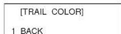
- Select 0 [TRAIL COLOR] then push the left button.
[TRAIL COLOR]
Note: 3 TRAIL COLOR shows numbers from 1 to 12 and the color currently selected for each number. Trail color changes at intervals according to trail length setting as follows:
12 hour trails: Trail color changes once every hour.
24 hour trails: Trail color changes once every two hours.
49 hour trails: Trail color changes once every four hours
1.3 Trail Color Shift
When there are many trails on the screen, especially when using long trails, it is difficult to distinguish past tracks from current tracks since they are the same color. With the trail color shift feature, tracks are painted in a different color from the point when color shift is activated. For example, the current track color is 1: FUCHSIA. Then, at the moment the trail color shift is made active, trails from that point will be painted in 2: MAROON.
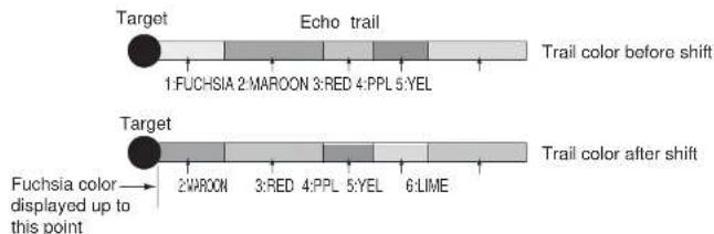
Note: At the moment the trail color shift is activated, the trail colors in effect after the time set in the TRAIL MODE box are erased. For example, the trail length is 12 HOURS and the time set in the TRAIL MODE box is 05:00. Then, using the illustration above as an example, 6: LIME will not be shown.
2 TRAIL GRAD in the TRAIL menu must be set to SINGLE and 8 TRAIL LENGTH to other than NORMAL in order to activate the trail color shift feature.
- Right-click the TRAIL MODE box.
- Select 0 [TRAIL COLOR] then push the left button.
1.4 Hiding Trails
Trails may be "hidden" (painted in light gray) for the period you specify, when 8 TRAIL LENGTH on the TRAIL menu is selected to other than "NORMAL".
- Right-click the TRAIL MODE box.
| [TRAIL MENU] | |
| 1 | TRAIL MODEREL/TRUE |
| 2 | TRAIL GRADSINGLE/MULTI |
| 3 | NARROW TRAILOFF/1/2 |
| 4 | TRAIL LEVEL1/2/3/4 |
| 5 | TRAIL RESTARTOFF/ON |
| 6 | TRAIL COPYOFF/ON |
| 7 | OS TRAILOFF/ON |
| 8 | TRAIL LENGTHNORMAL/12H/24H/48H |
| 9 | TRAIL HIDE*START 00:00END 00:00 |
| 0 | [TRAIL COLOR]* |
* Shown when 8 TRAIL LENGTH is selected to other than "NORMAL".
-
Select 9 TRAIL HIDE then push the left button.
-
Use the scrollwheel to set START time: Spin the scrollwheel to set time then push it to confirm
1.5 Trail Eraser
The trail eraser allows you to erase a portion of a trail you select. This is useful when the screen becomes cluttered with trails.
- Place the cursor inside the effective display area.
- Spin the scrollwheel to show "T-ERASER L=ERASE / EXIT" in the guidance box at the bottom right-hand corner on the screen.
$$ \begin{array}{c} \text {T - ERASER /EXIT} \ \text {L = ERASE /} \end{array} $$
- Push the left button successively to select eraser width, from the four choices shown below. (This also may be done anytime while the guidance box shows the above-mentioned indication.)

Small

Medium

Large
Extra Large
-
Do one of the following to erase a target trail:
-
To erase a specific point or if you are using a trackball control unit (RCU-015 or RCU-016), place the cursor on the part of the trail to erase and long-push the left button. Trails within the track eraser are erased. To continue erasing, repeat the above procedure.
- To erase trails in a wide area, select trail with the cursor, and roll the trackball while pressing and holding down the [ALARM ACK] key. Trails which contact the edge of the track eraser are erased.
A beep sounds when the right button, [ALARM ACK] key or trackball is operated.
Note: The trail orscor feature orscor only track currently shown on the display. To
1.6 Narrow Trails
Target trails may be painted with thinner lines if desired. This can be useful when there are a lot of target trails on the screen.
- Right-click the TRAIL MODE box to display the TRAIL menu.
- Select 3 NARROW TRAIL then push the left button.
- Select OFF, 1 or 2 as appropriate then push the left button. "2" is thinner than "1".
- Push the right button to close the menu.
1.7 Preventing True Sea Clutter Trails
You can prevent the tracing of true sea clutter trails near your ship to view the situation around your ship more easily. Further, you may enable/disable your ship's trails.
- Right-click the TRAIL MODE box at the bottom right corner on the screen.
- Select 7 OS TRAIL then push the left button.
- Select OFF, 1 or 2 as appropriate then push the left button.
| Setting | Draw your ship's track | Prevent true sea clutter trails near your ship |
| OFF No | No | |
| 1 | Y | e s |
| 2 | N | o |
Y
- Right-click to close the menu.
2. CURSORS
2.1 Crosshairs Cursor Size
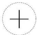
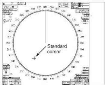
The size of the crosshairs cursor (+) can be chosen from small or large. The large cursor is useful when a large echo masks the small cursor.
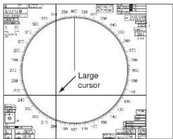
- Place the cursor inside the effective display area.
- If the guidance box is currently showing "TARGET DATA & ACQ / CURSOR MENU", push the right button once to show the CURSOR menu. If it is not currently shown, push the right button twice.
[CURSOR MENU]
2↓
TARGET DATA & ACQ*/ TARGET CANCEL*/ ARP TGT DATA & ACQ*/
2.2 Net Cursor
The net cursor is used to depict your fishing net on the radar display. It is especially useful for bottom trawlers for knowing where the net is located. Enter the dimensions of your net in the menu to show the net in scale on the display.
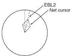
Activating the net cursor
- Left-click the MENU box.
- Select 2 [MARK] then push the left button.
- Select [9 EBL, VRM, CURSOR SET] then push the left button.
[EBL, VRM, CURSOR SET] 1 BACK 2 EBL1 REL/TRUE 3 EBL2 REL/TRUE 4 VRM1 NM/SM/km/kyd 5 VRM2 NM/SM/km/kyd 6 CURSOR BEARING REL/TRUE 7 CURSOR RANGE
- Select 2 CURSOR then push the left button.
- Select ON then push the left button to enable the net cursor. EBL2 is then automatically turned on.
- Push the right button four times to close the menu.
Setting net cursor dimensions, adjusting net cursor orientation
- Left-click the MENU box.
- Select 2 [MARK] then push the left button.
- Select 9 [EBL, VRM, CURSOR SET] then push the left button.
- Select 8 [ GURSOR SHAPE] then push the left button.
[◇CURSOR SHAPE]
1 BACK
2 ◇ CURSOR OFF/ON
3 FRONT HALF LENGTH
0.0m
4 REAR HALF LENGTH
0.0m
5 NET WIDTH
0.0m
6 ROTATE STEP
360°/32 POINTS
WARP LENGTH 0.0m
- Set net cursor dimensions as follows, referring to the illustration at right.


- Use the EBL offset feature to anchor the net cursor at net origin point.
1) Push the EBL OFFSET key.
2) Use the trackball to set net origin point.
3) Press the EBL OFFSET key to anchor the net cursor.
- Steer the vessel so your ship's trail runs along the net cursor then throw the net.
2.3 Cursor Data Display
The cursor data box, which is located at the top right corner on the screen, can show latitude and longitude position of the cursor, X- and Y-coordinates, and range and bearing from your ship to the cursor. Further, if set and drift corrections are disabled, two cursor data boxes may be shown, to display two sets of position information.
Left-click the cursor data box successively to change cursor data in the sequence shown below.
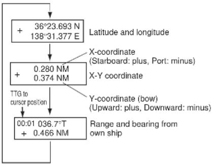
flowchart
graph TD
    A["+ 36°23.693 N\n138°31.377 E"] --> B["+ 0.280 NM\n0.374 NM"]
    B --> C["00:01 036.7°T\n+ 0.466 NM"]
    D["LL TG to cursor position"] --> C
    E["Range and bearing from own ship"] --> C
    F["X-coordinate\n(Starboard: plus, Port: minus)"] --> B
    G["Y-coordinate (bow)\n(Upward: plus, Downward: minus)"] --> C
    H["Latitude and longitude"] --> A
    I["LL TG to cursor position"] --> C
2.4 Bearing Scale Format
The bearing scale can be displayed with numerical indications or 32 compass points.
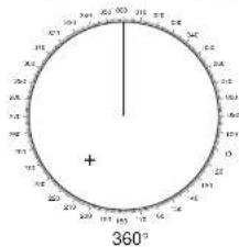
- Left-click the MENU box.
- Select 2 [MARK] then push the left button.
- Select 9 [EBL, VRM CURSOR SET] then push the left button.
[EBL, VRM, CURSOR SET]
1 BACK
2 EBL1
REL/TRUE
3 EBL2
REL/TRUE
4 VRM1
NM/SM/KM/kyd
5 VRM1
NM/SM/KM/kyd
6 CURSOR BEARING REL/TRUE
7 CURSOR RANGE
NM/SM/KM/kyd
A LOCURSOR SHAPEI
3. OTHER FUNCTIONS
3.1 Echo Display Area
Three types of echo display areas are available: circle, wide and all. "All" uses the entire screen, which allows you to view long-range targets.
CIRCLE WIDE ALL
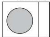
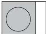
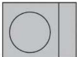
□ : Echo display area
- Left-click the MENU box at the right side of the screen.
- Select 1 [ECHO] then push the left button to show the ECHO menu.
[ECHO]
1 BACK
2 2 ^ND ECHO REJ
OFF/ON
3 TUNE INITIALIZE
4 PM ^x1
OFF/ON
5 SART
OFF/ON
6 WIPER
OFF/1/2
7 ECHO AREA
3.2 Turning On-screen Boxes On/Off
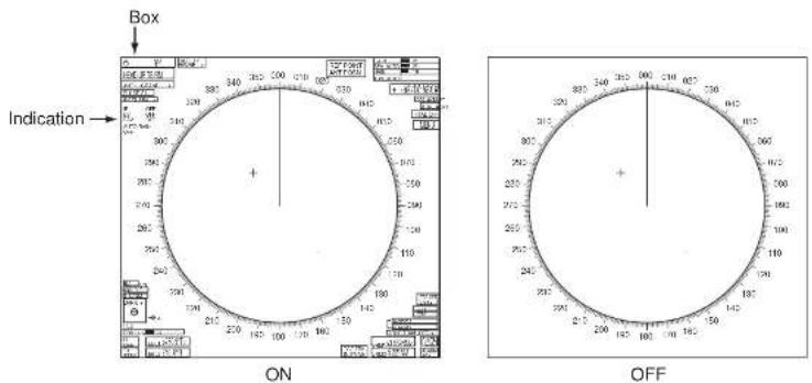
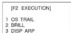
If you are using the "wide" or "all" echo display area, the on-screen boxes and indications outside the effective display area (data fields at right 1/4 of screen are not included) may obscure radar targets. To view those radar targets, you can turn the boxes and indications off, by a function key. The default setting of the F2 key turns the boxes on/off. If the function of the F2 key is set for other than ICON DISP, program for that function (see "Programming the F1, F2 and F3 keys" on page 24) then follow the procedure below.
- Press the F2 key.
3.3 Radar Picture Color
Radar echoes may be displayed in a single color of yellow, green or white, or in multi-color. The multi-color feature paints echoes in red, yellow or green, in order of descending strength.
- Set the cursor in the BRILL box at the lower left corner.

- Right-click the box to show the BRILL1 menu.
![[BRILL1 MENU (1/2)] 1 ECHO COLOR YEL/GRN/ WHT/COLOR 2 BKGD COLOR BLK-GRN/ BLK-RED/ BLU-CIR/ BLU/BRT-BLU 3 PANEL DIMMER 4 CHARACTER 5 CURSOR 6 ECHO 7 TRAIL 8 HL 9 RING 0 NEXT](/content/2026/05/925548/images/a4e0ddaf43a521008450fd78bf2c0819013f6af036672ba565bb94a0d52f747f.jpg)
- Select 1 ECHO COLOR then push the left button.
- Select YEL, GRN, WHT or COLOR as applicable then push the left button.
- Push the right button to close the menu.
3.4 Bearing Reference
The EBL bearing (and cursor bearing) can be referenced to your ship heading (relative bearing) or North (true bearing). This radar indicates true or relative bearings with an R or T in the EBL and cursor data boxes. In the head-up and cursor gyro modes you can switch between true and relative bearings. In all other modes true bearings are normally displayed. Heading signal is required to display true bearing.
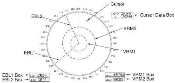
radar
| Category | Value | | ---------------- | ------ | | EBL1 Box | 30.0 V | | EBL2 Box | 36.2 V | | EBL2 Data Box | 30.0 V |To select bearing reference, do the following:
- Left-click the MENU box.
- Select 2 [MARK] then push the left button.
- Select 9 [EBL, VRM CURSOR SET] then push the left button.
[EBL, VRM, CURSOR SET]
1 BACK
2 EBL1
REL/TRUE
3.5 VRM, Cursor Unit
The unit of range measurement for the VRM and cursor can be selected from among nautical mile, statute mile, kilometer and kiloyard. See the illustration on the previous page for location of VRM and cursor data.
- Left-click the MENU box.
- Select 2 [MARK] then push the left button.
- Select 9 [EBL, VRM CURSOR SET] then push the left button.
- Select 4 VRM1, 5 VRM2 or 7 CURSOR RANGE as applicable then push the left button.
- Select NM, SM, km or kyd as applicable then push the left button.
- Push the right button three times to close the menu.
3.6 Pop-up Guidance
You can show pop-up guidance for the on-screen boxes. With this feature turned on, simply set the cursor inside a box to show pop-up guidance for that box.
- Left-click the MENU box at the right side of the screen.
- Select 9 [CUSTOMIZE/TEST] then push the left button.
- Select 7 [OPERATION] then push the left button.
[OPERATION (1/2)]
1 BACK
2 WHEEL DRIVE
NORMAL/REVERSE
3 KEY BEEP
OFF/LO/MID/HI
4 REMOTE KEY
F*-KEY/
4. FUNCTION KEYS (F1 - F4)
4.1 F1, F2 and F3 Keys
The F1, F2 and F3 keys can be used to automate complex or repetitive tasks. Each key may be programmed with ten functions. Simply press a key to execute program assigned.
Operating F1, F2 and F3 keys
The table below shows the default functions of the F1, F2 and F3 keys.
Default functions of F1, F2 and F3 keys
| F1 key F2 key F3 key | ||
| 1. PICTURE 1. OS TRAIL 1. OWN TRACK OFF/ON | ||
| 2. IR 2. BRILL 2. OWN TRACK COLOR | ||
| 3. ES 3. DISP ARP 3. TGT TRACK OFF/ON | ||
| 4. EAV 4. DISP AIS 4. TGT TRACK COLOR | ||
| 5. PULSE LENGTH 5. DISPLAY | SELECT 5. OWN TRACK DISPLAY | |
| 6. WIPER | 6. ICON DISP | 6. TARGET TRACK DISPLAY |
| 7. ECHO AREA | 7. PICTURE1 | 7. GPS BUOY DISPLAY |
| 8. NO FUNCTION | 8. PICTURE2 | 8. MAP MARK COLOR |
| 9. NO FUNCTION | 9. PICTURE3 | 9. DISP WPT NO. |
| 0. NO FUNCTION | 0. PICTURE4 | 0. DISP WPT NAME |
- Press F1, F2 or F3 key. For example, press the F1 key.

Programming the F1, F2 and F3 keys
- Press a function key (F1, F2 or F3) twice. For example, press the F1 key.
[F1 REGISTER]
1 [PICTURE]
2 [IR]
3 [ES]
4 [EAV]
5 [PULSE LENGTH]
6 [WIPER]
7 [ECHO AREA]
8 [NO FUNCTION]
9 [NO FUNCTION]
0 [NO FUNCTION]
- Select function desired then push the left button. For example, select 1 [PICTURE].
[F1-1]
1 BACK
2 [ECHO]
3 [STD KEY]
4 [ARP-AIS]
5 [OPERATION]
6 [PICTURE]
7 [MARK]
8 [PLOTTER]
9 [NAV LINE •WPT]
0 NO FUNCTION
- Select function desired then push the left button. The corresponding menu appears. See the next page.
[F1-1-ECHO]
1 BACK
2 PICTURE
IR
ES
EAV
NOISE RED ANGELIC
ANT SELECT PULSE LENGTH
A/C SEA SELECT
AUTO RAIN SELECT
TUNE SELECT:
VIDEO CONTRAST1
VIDEO CONTRAST2
ANT HEIGHT?
SEA CONDITION
2ND ECHO REJ
SART
WIPER
ECHO AREA
[F1-1-STD KEY]
1 BACK
2 ALARMACK
STRY TX
HL OFF
MODE
OFF CENTER
CU TM RESET
INDEX LINE VEGETED TIN
VECTOR MODE
TARGET LIST:
TRAIL TIME
TRAIL GRAD
OS TRAIL
BRILL
MENU
RANGE UP:
HANGE DOWN
TARG
TARGET CANC
[F1-1-ARP-AIS]
1 BACK
2
DISP ARP
DISP AIS TARGET
TARGET DATA/ACQ BAST ROSN INTERVA
PASTYSON INTEVALE REE MARK:
CPA LIMIT
CPA
TCPA
TARGET LIST SORTS
TRIAL MANELVER
ARPAIS FUSION:
ARP SYMBOL COLOR
ARP SYMBOL SIZE
ARP FAST COLOR ARP FAST COINES
AISMESSAGE!
AIS SYMBOL COLOR
AIS SYMBOL SIZE:
AIS PAST COLOR:
AIS PAST POINTS
TRIAL MODE CHANGE
[F1-1-OPERATION]
1 BACK
2
ECHO COLOR
BACK COLORING
HIND WATCH ALARM RESET
ZOOM
DISPLAY SELECT:
RADAR COMBINE
MOB
USER DEFAULT
ANCHOR WATCH!
COLOR SHIFT
ICON DISP
OWN TRK ALL ERASE
TGT TRK ALL ERASE
[F1-1-PICTURE]
1 BACK
PICTURE1:
PICTURE2
PICTURE3
PICTURE4:
NEAR
NEAR BUOY
FAR BUDY:
ROUGH SEA
SHIP:
NEAR BIRD
FAH BIRD
[F1-1-MARK]
1 BACK
2
STERN MARK:
INDEX LINE
INDEX LINE MODE:
EBL OFFSET BASE
EBL1 BEARING
EBL2 BEARING
CURSOR BEARING
BARGE MARK OCURECE
* Sonson
[F1-1-PLOTTER]
1 BACK
2 CHART COLOR
OWN TRACK OFFION
OWNTRACK COLOR
TGT TRACK OFF/ON
TGT TRACK COLOR
CURSOR L'L ALIGN
MARK ALL ERASE
WP ALL ERASE
NAV LINE ALL CHASE GRIDDISPLAY
OWNTRACK DISPLAY
TARGET TRACK DISPLAY
MARK DISPLAY:
LAND DENSITY DISPLAY:
PLACE NAME DISPLAY
COAST LINE DISPLAY:
CONTOUR LINE DISPLAY?
[F1-1-NAV LINEWPT]
1 BACK
NAV LINE DATA
ARRIVAL WPT ALARM
DISP WPT NO:
DISP WPT NAM
SKIP NEXT WPT:
TURNING LINE?
DEPTH
DEPTH GRAPH SCALE
CURRENT
WIND TEM
DATE TIME:
WPT DATA
Functions available with F1-F3 keys: ECHO category
| Item Function | Settings | |
| PICTURE Select picture | setup condition. PICTURE1, PICTURE2, PICTURE3, PICTURE4, NEAR, FAR, NEAR BUOY, FAR BUOY, ROUGH SEA, SHIP, HARBOR ^1 , COAST ^1 , NEAR BIRD ^2 , FAR BIRD ^2 ^1 10 kW/25 kW ^2 50 kW/60 kW | |
| IR Enable/disable interferencerejector. | OFF, 1, 2, 3 | |
| ES Enable/disable echo stretch. OFF, 1, 2, 3 | ||
| EAV Enable/disable echo averaging. OFF, 1, 2, 3 | ||
| NOISE REJ Enable/disable noise rejector. OFF, ON | ||
| ANT SELECT Select antenna unit. | ||
| PULSE LENGTH Select pulse length. 10 kW/25 kW models | 0.125, 0.25, 0.5 NM: S10.75, 1, 1.5, 2 NM: S1, S2, M13, 4 NM: S2, M1, M2, M36, 8 NM: M1, M2, M3, L12, 16, 24 NM: M2, M3, L32, 48, 96, 120 NM: L50 kW/60 kW models0.125, 0.25, 0.5 NM: S0.75, 1, 1.5, 2 NM: S, M13, 4 NM: M1, M26, 8, 12, 16, 24 NM: M2, L32, 48, 96, 120 NM: L | |
| A/C SEA SELECT | Select A/C SEA adjustment | AUTO, MANUAL |
A/C SEA SELECT
Select A/C SEA adjustment
AUTO MANUAL
Functions available with F1-F3 keys: STD KEY category
| Item Function Settings | ||
| ALARM ACK Silence alarm buzzer. | ||
| STBY TX Alternate between standby and TX. | ||
| HL OFF Hide heading line temporarily. | ||
| MODE Select presentation mode. Head-up, Cursor gyro, North-up, Course-up, True motion | ||
| OFF CENTER Off center the display. | ||
| CU TM RESET Reset position in course-up/true motion. | ||
| INDEX LINE Display index line. IL1, IL2 | ||
| VECTOR TIME Select vector time. 30 s, 1-5 min (one-minute intervals), 20 min, 30 min, 40 min, 50 min, 60 min | ||
| VECTOR MODE Select vector mode. Relative vector, true vector | ||
| TARGET LIST | Display ARP target list. | |
| TRAIL TIME | Select trail time. | "Standard" trail length: OFF, 00:15, 00:30, 01:00, 03:00, 06:00, 15:00, 30:00, Continuous |
| "12h" trail length: OFF, 00:30, 01:00, 03:00, -6:00, 12:00, Continuous | ||
| "24h" trail length: OFF, 01:00, 02:00, 03:00, 06:00, 12:00, 18:00, 24:00, Continuous | ||
| "48h" trail length: OFF, 02:00, 04:00, 08:00, 16:00, 24:00, 36:00, 48:00, Continuous | ||
| TRAIL GRAD | Select trail gradation. | Single (color), Multi (single color) |
Functions available with F1-F3 keys: ARP•AIS category
| Item Function Settings | ||
| DISP ARP Enable/disable | ARP display. OFF, MANUAL, AUTO, AUTO | TO/MANUAL |
| DISP AIS Show/hide AIS display. OFF, ON | ||
| TARGET DATA&ACQ ARP | Acquire ARP target.Display ARP target data.AIS: Activated sleeping AIS target.Display AIS target data. | |
| PAST POSN INTERVAL Select past position interval. | ||
| REF MARK Inscribe reference mark. | ||
| CPA LIMIT Enable/disable | CPA alarm. OFF/ON | |
| CPA Set CPA limit. 0.5, 1.0, 1.5, 2.0, 3.0, 4.0, 5.0, | 6.0 (nm) | |
| TCPA | Set time of closest approach. | 1, 2, 3, 4, 5, 6, 12, 15 (min) |
| TARGET LIST SORT | Select target list sort method. | CPA, TCPA, BCR, BCT, DISTANCE, SPEED |
| TRIAL MANEUVER | Start trial maneuver. | |
| ARP•AIS FUSION | Enable/disable ARP•AIS target fusion. | OFF, ON |
| ARP SYMBOL COLOR | Select ARP symbol color. | RED, GREEN, BLUE, YELLOW, LIGHT-BLUE, PURPLE |
| ARP SYMBOL SIZE | Select ARP symbol size. SMALL, STANDARD, LARGE | |
| ARP PAST COLOR | Select ARP past position color. | RED, GREEN, BLUE, YELLOW, LIGHT-BLUE, PURPLE |
| ARP PAST POINTS | Set number of ARP past points to show. | 5, 10 |
| AIS MESSAGE | Show/hide the "you got mail" symbol | |
Functions available with F1-F3 keys: OPERATION category
| Item Function | Settings | |
| ECHO COLOR Select echo | o color. YELLOW, GREEN, WHITE, | MULTI |
| BACK COLOR Select back | ground color. BLACK(GREEN characters),BLACK(RED characters),ECHO BLUE, BLUE, DARKBLUE | |
| RING Show/hide fixed range rings. OFF, ON | ||
| WATCH ALARM RESET | Reset watch alarm. | |
| ZOOM Enable/disable zoom. | ||
| DISPLAY SELECT Select | display mode. RADAR. RADAR+PLOTTER,PLOTTER | |
| RADAR COMBINE Select | dual-range display format. OFF, MIX, COMBINE | |
| MOB | Inscribe MOB mark. | |
| USER DEFAULT | Restore user defaults for [F1]-[F3].(When "F-KEY" is selected at USERDEFAULT in OPERATION (2/2) menu.1. Set equipment as desired.2. Display F1, F2 or F3 menu as appli-cable.3. Choose USER DEFAULT and long-push (more than one second) the left button.4. To recall a setting, select F1, F2 or F3 menu as applicable and choose USER DEFAULTSThe radar is then set to stand-by and "USER DEFAULT" appears at the bottom right corner. | |
| TLL | Output cursor-selected radar target's position to chart plotter. | |
| ANGUOR WATCH | Enable/disable anchorwatch | OFF, ON |
ANCHOR WATCH
Fudible, Goodness
OFF ON
Description of functions available with F1-F3 keys: MARK category
| Item Function | Settings | |
| OWN SHIP MARK Enable/disable your ship mark. OFF, ON | ||
| STERN MARK Enable/disable stern mark. OFF, ON | ||
| INDEX LINE Select number of index lines to display. 1, 2, 3, 6 | ||
| INDEX LINE MODE Select index line mode. HORIZONTAL, VERTICAL | ||
| EBL OFFSET BASE Select offset EBL reference point. STAB GND, STAB NORTH, STAB HEAD | ||
| EBL1 BEARING Set bearing reference for EBL1. RELATIVE, TRUE | ||
| EBL2 BEARING Set bearing reference for EBL2. RELATIVE, TRUE | ||
| CURSOR BEARING Set bearing reference for cursor. RELATIVE, TRUE | ||
| BARGE MARK | Enable/disable barge marks. OFF, ON | |
| CURSOR SHAPE | Enable/disable net cursor. | OFF, ON |
Description of functions available with F1-F3 keys: PLOTTER category
| Item | Function Settings | |
| CHART COLOR | Select chart color. | GREEN, YELLOW, LIGHT-BLUE, ORANGE, GRAY |
| OWN TRACK OFF/ON | Hide/show your ship's track. | OFF, ON |
| OWN TRACK COLOR | Select color of your ship's track. | RED, GREEN, YELLOW, LIGHT-BLUE, PURPLE, WHITE |
| TGT TRACK OFF/ON | Hide/show tracks of targets. | OFF, 10 s, 30 s, 1 min, 3 min, 6 min, 15 min |
| TGT TRACK COLOR | Select color for target tracks. | RED, GREEN, YELLOW, LIGHT-BLUE, PURPLE, WHITE |
Description of functions available with F1-F3 keys: PLOTTER category
| Item | Function | Settings |
| DANGER HIGHLIGHT Show/hide danger highlights OFF, ON | ||
| PROHIBITED AREA DISP | Show/hide prohibited areas. OFF, ON | |
| BUOY DISPLAY Show/hide buoys. OFF, ON | ||
| GPS BUOY DISPLAY Show/hide GPS buoys. OFF, ON | ||
| TARGET TRACK MODE Select target track color assignment method. | ALL, INDIVIDUAL | |
| MAP DISPLAY Show/hide radar map. OFF, ON | ||
| MAP MARK COLOR Select map mark color RED, GREEN, BLUE, | YELLOW, LIGHT-BLUE, PURPLE, WHITE | |
Description of functions available with F1-F3 keys: NAV LINE•WPT category
| Item Function | Settings | |
| NAV LINE DATA | Show/hide nav line data. | OFF, EXTERNAL,INTERNAL, WAYPOINT |
| ARRIVAL WPT ALARM | Enable/disable arrival waypoint alarm. | OFF, ON |
| DISP WPT NO. | Show/hide waypoint number. | OFF, ON |
| DISP WPT NAME | Show/hide waypoint name | OFF, ON |
| SKIP NEXT WPT | Skip next waypoint in a route. | |
| TURNING LINE | Show/hide turning line. | OFF, ON, REVISED |
| DEPTH | Show/hide depth indication. | OFF, m, ft |
| DEPTH GRAPH SCALE | Select graph scale. | 10, 20, 50, 100, 200, 500 (m) |
| CURRENT | Show/hide current data. | OFF, ON |
4.2 Operating the F4 Key
The F4 key is a user-programmable macro key for automating complex or repetitive tasks. The user may program this key with as many as ten functions.
Registering a program to the F4 key
- Press the F4 key twice to show the F4 REGISTER menu. (Each press of the key displays the F4-REGISTER and F4 EXECUTION menus alternately.)
-
Select the number to register then push the left button. For example, select "1" and the F4-1 menu appears.
-
Select 2 TITLE then push the left button. A keyboard appears.
- Use the keyboard to enter program title, using up to 15 alphanumeric characters.
1) Place the cursor on a desired character.
2) Push the left button. Chosen character appears below TITLE in the menu. Numeric and alphabet may be directly entered from keyboard-equipped control unit.
3) Repeat steps 1 and 2 to complete the title.
Keyboard
[F4 REGISTER]
| 1 | [ ] |
| 2 | [ ] |
| 3 | [ ] |
| 4 | [ ] |
| 5 | [ ] |
| 6 | [ ] |
| 7 | [ ] |
| 8 | [ ] |
| 9 | [ ] |
| 0 | [ ] |
[F4-1]
| 1 | 2 | 3 | 4 | 5 | 6 | 7 | 8 | 9 | 0 | B$ | □ | □ |
| Q | W | E | R | T | Y | U | I | O | P | - | □ | □ |
| A | S | D | F | G | H | J | K | L | + | □ | □ | |
| Z | X | C | V | B | N | M | □ | , | . | ? | ||
| " | # | " | END |
Menu functions recordable to F4 key
| [ECHO] menu (main menu) [FUSION] menu | (main menu) |
| 2ND ECHO REJ FUSION TARGET | |
| PM GAP | |
| SART RANGE | |
| WIPER BEARING | |
| ECHO AREA SPEED | |
| [MARK] menu (main menu) COURSE | |
| OWN SHIP MARK | [PLOTTER] menu (main menu) |
| STERN MARK CHART COLOR | |
| INDEX LINE BEARING CURSOR L/L ALIGN | |
| INDEX LINE | [OWN TRACK] menu (main menu) |
| INDEX LINE MODE TRACK INTERVAL | |
| EBL OFFSET BASE POINT TRACK COLOR | |
| RING | [TGT TRACK] menu (main menu) |
| [BARGE MARK] menu (main menu) TRACK INTERVAL | |
| BARGE MARK TRACK COLOR MODE | |
| BARGE SIZE TRACK COLOR MODE | |
| ARRANGEMENT AUTO TARGET TRACK | |
| [EBL, VRM, CURSOR SET] menu (main menu) | [DISPLAY] menu (main menu) |
| EBL1 | GRID |
| EBL2 | OWN TRACK |
| CURSOR BEARING | TARGET TRACK |
| [CURSOR SHAPE] menu (main menu) | MARK |
| CURSOR | LAND DENSITY |
| FRONT HALF LENGTH | PLACE NAME |
| BEAR YELLOW LENGTH | CONTACT LINE |
Menu functions recordable to F4 key
| [NAV LINE/WPT] menu (main menu) [MARK] menu (box menu) | |
| NAV LINE DATA SOURCE MARK POSN (mark entry) | method) |
| NAV LINE WIDTH MAP DISPLAY | |
| ARRIVAL WPT ALARM MAP MARK COLOR | |
| TURNING LINE | [BRILL] menu (box menu) |
| DISP WPT NO. ECHO COLOR | |
| DISP WPT NAME BKGD COLOR | |
| [DATA BOX] menu (main menu) [TRAIL] menu (box menu) | |
| NAV DATA TRAIL MODE | |
| ZOOM TRAIL GRAD | |
| [PICTURE] menu (box menu) NARROW TRAIL | |
| INT REJECT TRAIL LEVEL | |
| ECHO STRETCH TRAIL RESTART | |
| ECHO AVERAGE TRAIL COPY | |
| NOISE REJ OS TRAIL | |
| AUTO STC TRAIL LENGTH | |
| AUTO RAIN | TRAIL HIDE |
| VIDEO CONTRAST | [ARPA] menu (box menu) |
| [PULSE] menu (box menu) | ARPA ON/OFF |
| Pulse length selection | |
| [CONDITION] menu (in PICTURE menu (box menu)) | |
| SEA CONDITION | |
| ANT HEIGHT | |
On-screen box operations recordable to the F4 key
| DISPLAY MODE box TRUE/REL VECTOR box |
| Select display mode. Select vector reference. |
| ANTENNA box ARP box |
| Select antenna. Turn ARP on/off. |
| PRESENTATION MODE box AIS box |
| Select presentation mode. Turn AIS on/off. |
| PICTURE box CPA ALARM box |
| Adjust radar picture. Enable/disable CPA alarm. |
| RANGE box CPA LIMIT box |
| Select display range. Set CPA limit. |
| TRAIL MODE box TCPA LIMIT box |
| Select echo trail time. Set TCPA limit. |
| ARP VECTOR box |
| Select ARP vector length. |
Operating the F4 key
- Press the F4 key to show the F4 EXECUTION menu.
| [F4 EXECUTION] |
| 1 BUOY |
| 2 DISTANT TARGET |
| 3 |
| 4 |
| 5 |
| 6 |
5. ANCHOR WATCH ALARM
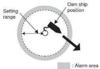
The anchor watch alarm informs you when your boat is moving when it should be at rest. When the anchor watch is active, a red dashed circle marks the anchor watch area.
- Left-click the MENU box.
- Select 3 [ALARM] then push the left button.
[ALARM]
1 BACK
2 TARGET ALARM MODE IN/OUT
3 TARGET ALARM LEVEL
1/2/3/4
4 WATCH ALARM
OFF/6M/10M/
12M/15M/20M
5 ALARM SOUND LEVEL OFF/LOW/MID/HIGH
6. VIDEO PLOTTER FUNCTIONS
The fishing specification radar has three operating modes: radar, radar plus plotter, and plotter.
6.1 Depth Contour with Depth Indication
Depth indication can be shown on depth contours.
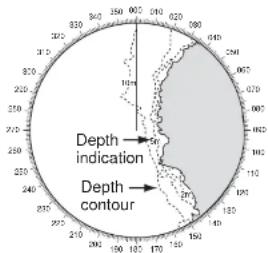
- Left-click the MENU box.
- Select 5 [PLOTTER] then push the left button.
- Select 7 [DISPLAY] then push the left button.
| [DISPLAY (1/2)] | |
| 1 | BACK |
| 2 | GRID |
| OFF/L/L |
6.2 Mark Settings
You can enter a mark to denote a reef, fishing ground, navigation buoy. The position of a mark is saved at the time of entry. The radar can store up 20,000 marks and lines.
This section shows you how to enter mark comment, and change its position and color.
Enabling, disabling mark comment input and mark position editing
- Use the trackball to put the cursor on the arrow in the MARK box at the bottom left-hand corner.

- Push the right button to show the MARK (1/2) menu.
[MARK MENU (1/2)]
1 ORIGIN MARK STAB GND/SEA
2 MARK KIND ORIGIN MARK(No.)/ ORIGIN MARK(SYM)/ MAP MARK/
WP 1\~50/ WP 51\~100/ WP 101\~150/ WP 151\~200/ OWN SHIP SHAPE
3 MARK POSN CURSOR/OS/L/L 4 MARK COMMENT
Entering mark comment, changing mark position
Mark comments can be entered and mark position changed when MARK COMMENT and MARK L/L EDIT are set to ON.
To show mark comments MAP DISPLAY on page 2 of the MARK menu must be set to ON.
- Use the trackball to put the cursor on the arrow in the MARK box at the bottom left-hand corner.
- Spin the scrollwheel to select desired mark then push the left button.
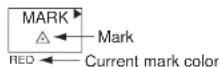
- Put the cursor on the location where you want to enter a mark then push the left button.
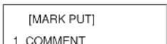
The location is circumscribed with a broken rectangle and the MARK ENTRY menu (1/2) appears. If 3 MARK POSN on the MARK ENTRY menu (1/2) is selected to OS (Own Ship), the broken rectangle appears at current position.
![[MARK PUT] 1 COMMENT* 2 POSITION** 34°44.44 N 135°21.20 E 3 CONFIRM](/content/2026/05/925548/images/f1d3f47851a7e7d755268d8edbb15b9fde605b4e96ff8176bcf4fed17fff102d.jpg)
*: Available when MARK COMMENT is ON.
**: Available when MARK L/L EDIT is ON.
- Select 1 COMMENT then push the left button.
- To edit mark position, select 2 POSITION then push the left button.
- Spin the scrollwheel to select numeric. Numeric may also be directly entered in case of keyboard-equipped control unit. After setting position, the values entered are colored blue.
- Select 3 CONFIRM then push the left button. The comment entered is placed next to on-screen mark. If the position of the mark was changed mark appears at the newly entered position.
- Push the right button to finish.
Selecting mark color
Mark color is available in red, green, blue, yellow, cyan (light-blue), magenta, and white.
- Use the trackball to put the cursor on the arrow in the MARK box at the bottom left-hand corner.
- Push the right button to show the MARK (1/2) menu.
- Spin the scrollwheel to select 0 NEXT then push the left button.
[MARK MENU(2/2)]
1 BACK
2 MAP DISPLAY OFF/ON
3 MAP MARK COLOR RED/GRN/BLU/YEL/CYA/MAG/WHT
- Select 3 MAP MARK COLOR then push the left button.
- Spin the scrollwheel to select color desired then push the left button. Selected color appears below the MARK box.
- Push the right button twice to close the menu
6.3 Track Settings
This section provides the procedures for how to select track recording parameters, select track color, and erase track.
Track recording interval
This radar can store 20,000 points of your track and 15,000 points of target tracks (1,000 points/target). The shorter the recording interval the smoother the track is drawn, however the recording time is greatly shortened. When the capacity for track is reached, the oldest track is erased to make room for the latest.
- Place the cursor in the MENU box then push the left button.
- Select [5 PLOTTER] then push the scrollwheel.
[PLOTTER]
1 BACK
2 CHART COLOR
GRN/YEL/CYA/
ORANGE/GRAY
3 [OWN TRACK]
4 [TGT TRACK]
5 CURSOR L/L ALIGN
OFF/ON
6 [DATA ERASE]
7 [DISPLAY]
8 [GPS BUOY]
- Spin the scrollwheel to select [3 OWN TRACK] or [4 TGT TRACK] as appropriate then push the left button.
[OWN TRACK]
1 BACK
[TGT TRACK]
1 BACK
Changing track color
Track can be colored red, green, blue, yellow. cyan, magenta, and white. It can be useful to change the color of ship's track to clearly differentiate past track from current track.
Changing the color of your ship's track
- Place the cursor in the MENU box then push the left button.
- Select [5 PLOTTER] then push the left button.
- Select [3 OWN TRACK] then push the left button.
- Select [3 TRACK COLOR] then push the left button.
- Select color desired then push the left button.
- Push the right button three times to close the menu.
Changing the color of target tracks
- Put the cursor in the track color selection box at the bottom of the screen.

- Long-push the left button to select track color changing format (ALL or IND(individual).
IND: Change color of specific target's track.
ALL: Change color of all target tracks.
- Push the left button to select color. The color selection changes cyclically in the order of red, blue, green, light-blue, magenta, white, red...
The color of target tracks can be automatically changed as shown in the table, by setting turning on 5 AUTO TARGET TRACK in the TGT TRACK menu.
AUTO TARGET TRACK status and track color
| AUTO TARGET TRACK "ON" AUTO TARGET TRACK "OFF" | ||
| ALL When track is drawn____ | When track is drawnManually acquire a target. The track of a manually acquired target is drawn in the color specified if the target selected by using the TARGET TRACK ON* feature. | |
| When color is changedThe color of all track is changed at the moment new color is selected. | When color is changedThe color of all track is changed at the moment new color is selected. | |
| INDIVIDUAL When track is drawn____ | When track is drawnManually acquire a target. The track of a manually acquired target is drawn in the color specified if the target selected by the TARGET TRACK ON* feature. To change track color of individual target and acquire the target by using the TARGET TRACK ON* feature. | |
| When color is changedCurrent track is not affected when color is changed. To change track color, select color desired and cancel tracking of target. Reacquire the target, and its track is then drawn in the color specified.Note:When 5 AUTO TARGET TRACK is switched from ON to OFF, track display is turned off from the moment of switching. If AUTO TARGET TRACK is again switched ON when INDIVIDUAL is active, the tracks of all targets (1-15) are | When color is changedCurrent track is not affected when color is changed. To change track color, select desired color and turn off the track of the target by using the TARGET TRACK OFF* feature. Select the target by using the TARGET TRACK ON feature, and the target's track is drawn in the color speci-fied. | |
Erasing track with the cursor
You may erase your ship's track or any target's track directly on the screen, by two points or area. Select the erasure method then erase track.
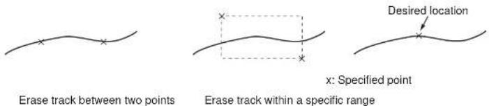
Selecting erasure method
Select the erasure method for own track and target track as follows:
- Left-click the MENU box.
- Select 5 [PLOTTER] then push the left button.
- Select 8 [DATA ERASE] then push the left button.
[DATA ERASE]
1 BACK
2 OWN TRACK
RED/GRN/BLU/YEL/
CYA/MAG/WHT/
30%/50%/80%/ALL
3 TARGET TRACK RED/GRN/BLU/YEL/CYA/MAG/WHT/30%/50%/80%/ALL
4 MARK ALL ERASE
Erasing track between two points, area
- Place the cursor inside the effective display area.
- Spin the scrollwheel to show OWN TRACK DELETE/EXIT or TGT TRACK DELETE/EXIT in the guidance box at the bottom right-hand corner on the screen, whichever track you want to erase.
| OWN TRACK/EXIT DELETE/ | TGT TRACK DELETE/EXIT |
-
Use the trackball to place the cursor at the top-left corner of the area (or 1st point in case of erasure by two points) then push the left button.
-
Use the trackball to drag the cursor at the bottom-right corner of the area (or 2nd point in case of erasure by two points). If the erasure method (chosen on the previous page) is "AREA", a rectangle appears when you start dragging the cursor.
-
Push the left button to erase track.
-
Push the right button to quit.
Note that this function is automatically canceled if there is no erasure occurring in 30 seconds.
Erasing all track of a target
- Place the cursor inside the effective display area.
- Spin the scrollwheel to show TGT TRACK DELETE/EXIT in the guidance box at the bottom right-hand corner on the screen.
- Use the trackball to put the cursor on the track you want to erase then push the left button to erase track.
- Push the right button to quit.
| TGT TRACK /EXITDELETE |
Automatically displaying other target tracks
6.4 GPS Buoy
With connection of a GPS radio buoy locator, the information (GPS buoy marker and GPS buoy track) for up to seven GPS buoys may be shown on the radar screen. One application of a GPS buoy is to tether it to a fishing net to monitor net position. Each track may contain up to 20 track points. Marker color is available in red, green, blue, yellow, light-blue, magenta and white.
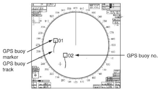
Enabling, disabling GPS buoy information
- Select the MENU box at the right side of the screen then push the left button.
- Select [5 PLOTTER] then push the left button.
- Select [8 GPS BUOY] then push the left button.
[GPS BUOY]
1 BACK
2 GPS BUOY
OFF/ON
3 ALL TRACK ERASE
7. ARP SYMBOLS
The ARP symbol is available in the 10 shapes shown in the illustration below. You can select shape desired as follows:
- Select target with trackball.
- Press the TARGET DATA key repeatedly to select symbol desired.


Note: If you are using the trackball-type control unit (RCU-015, RCU-016), ARP symbol shape cannot be chosen by the above procedure. However, you can program a function key to do so, with the combination of the "STD KEY" category and the option "TARGET DATA." For how to program a function key, see section 4.1.2.
8. DISPLAYING PICTURE FROM EXTERNAL RADAR
The picture from an external radar connected to the SUB DISPLAY termina can be displayed on the FAR-2xx7 series display.
- Use the trackball to set the pointer on the triangle in the ANTENNA box at the upper left corner on the display.
ANT2 X-BAND
- Right click to show the ANT INFORMATION menu.
[ANT INFORMATION]
ANT NO 1
BAND : X-BAND
MODEL:12
POS : MAIN TOP
ANT NO 2
BAND : X-BAND
MODEL:12
POS : FORE
ANT NO 3
BAND :
MODEL
POS
ANT NO 4
BAND :
MODEL
POS
OWN RADAR NO: 1
8 SUB MONITOR
OFF/ON
9 INTER SW PRIORITY
9. MENU OVERVIEW
Menu tree
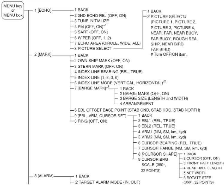
flowchart
graph TD
    A["MENU key or MENU box"] --> B["1 [ECHO"]]
    A --> C["2 [MARK"]]
    A --> D["3 [ALARM"]]

    B --> B1["1 BACK"]
    B --> B2["2 2ND ECHO REJ (OFF, ON)"]
    B --> B3["3 TUNE INITIALIZE"]
    B --> B4["4 PM (OFF, ON)¹"]
    B --> B5["5 SART (OFF, ON)"]
    B --> B6["6 WIPER (OFF, 1, 2)"]
    B --> B7["7 ECHO AREA (CIRCLE, WIDE, ALL)"]
    B --> B8["8 PICTURE SELECT"]

    C --> C1["1 BACK"]
    C --> C2["2 PICTURE SELECT# (PICTURE 1, PICTURE 2, PICTURE 3, PICTURE 4, NEAR, FAR, NEAR BUOY, FAR BUOY, ROUGH SEA, SHIP, NEAR BIRD, FAR BIRD)"]
    C --> C3["# Turn OFF/ON item."]

    D --> D1["1 BACK"]
    D --> D2["2 OWN SHIP MARK (OFF, ON)"]
    D --> D3["3 STERN MARK (OFF, ON)"]
    D --> D4["4 INDEX LINE BEARING (REL, TRUE)"]
    D --> D5["5 INDEX LINE (1, 2, 3, 6)"]
    D --> D6["6 INDEX LINE MODE (VERTICAL, HORIZONTAL)²"]
    D --> D7["7 [BARGE MARK"]⁶]
    D --> D8["8 EBL OFFSET BASE POINT (STAB GND, STAB HDG, STAB NORTH)"]
    D --> D9["9 [EBL, VRM, CURSOR SET"]]
    D --> D10["0 RING (OFF, ON)"]

    D1 --> D1a["1 BACK"]
    D1 --> D1b["2 BARGE MARK (OFF, ON)"]
    D1 --> D1c["3 BARGE SIZE (LENGTH and WIDTH)"]
    D1 --> D1d["4 ARRANGEMENT"]

    D2 --> D2a["1 BACK"]
    D2 --> D2b["2 EBL1 (REL, TRUE)"]
    D2 --> D2c["3 EBL2 (REL, TRUE)"]
    D2 --> D2d["4 VRM1 (NM, SM, km, kyd)"]
    D2 --> D2e["5 VRM2 (NM, SM, km, kyd)"]
    D2 --> D2f["6 CURSOR BEARING (REL, TRUE)"]
    D2 --> D2g["7 CURSOR RANGE (NM, SM, km, kyd)"]
    D2 --> D2h["8 [CURSOR SHAPE"]]
    D2 --> D2i["9 CURSOR BRG SCALE (360°, 32 POINTS)"]

    D3 --> D3a["1 BACK"]
    D3 --> D3b["2 TARGET ALARM MODE (IN, OUT)"]

    style A fill:#f9f9f9,stroke:#333
    style B fill:#f9f9f9,stroke:#333
    style C fill:#f9f9f9,stroke:#333
    style D fill:#f9f9f9,stroke:#333
(Continued from previous page)
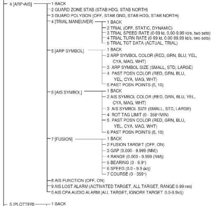
flowchart
graph TD
    A["4 [ARP-AIS"]] --> B["1 BACK"]
    A --> C["2 GUARD ZONE STAB (STAB HDG, STAB NORTH)"]
    A --> D["3 GUARD POLYGON (OFF, STAB GND, STAB HDG, STAB NORTH)"]
    A --> E["4 [TRIAL MANEUVER"]]
    E --> F["1 BACK"]
    E --> G["2 TRIAL (OFF, STATIC, DYNAMIC)"]
    E --> H["3 TRIAL SPEED RATE (0-99 kt, 0.00-9.99 kt/s, two sets)"]
    E --> I["4 TRIAL TURN RATE (0-99 kt, 0.00-99.99 kt/s, two sets)"]
    E --> J["5 TRIAL TGT DATA (ACTUAL, TRIAL)"]
    A --> K["5 [ARP SYMBOL"]]
    K --> L["1 BACK"]
    K --> M["2 ARP SYMBOL COLOR (RED, GRN, BLU, YEL, CYA, MAG, WHT)"]
    K --> N["3 ARP SYMBOL SIZE (SMALL, STD, LARGE)"]
    K --> O["4 PAST POSN COLOR (RED, GRN, BLU, YEL, CYA, MAG, WHT)"]
    K --> P["5 PAST POSN POINTS (5, 10)"]
    A --> Q["6 [AIS SYMBOL"]]
    Q --> R["1 BACK"]
    Q --> S["2 AIS SYMBOL COLOR (RED, GRN, BLU, YEL, CYA, MAG, WHT)"]
    Q --> T["3 AIS SYMBOL SIZE (SMALL, STD, LARGE)"]
    Q --> U["4 ROT TAG LIMIT (0 - 358°/MIN)"]
    Q --> V["5 PAST POSN COLOR (RED, GRN, BLU, YEL, CYA, MAG, WHT)"]
    Q --> W["6 PAST POSN POINTS (5, 10)"]
    A --> X["7 [FUSION"]]
    X --> Y["1 BACK"]
    X --> Z["2 FUSION TARGET (OFF, ON)"]
    X --> AA["3 GAP (0.000 - 9.999 (NM))"]
    X --> AB["4 RANGE (0.000 - 9.999 (NM))"]
    X --> AC["5 BEARING (0 - 9.9°)"]
    X --> AD["6 SPEED (0.0 - 9.9 (kl))"]
    X --> AE["7 COURSE (0 - 358°)"]
    A --> AF["8 AIS FUNCTION (OFF, ON)"]
    A --> AG["9 AIS LOST ALARM (ACTIVATED TARGET, ALL TARGET, RANGE 0-99 nm)"]
    A --> AH["0 AIS CPA AUDIO ALARM (ALL TARGET, IGNORE TARGET 0.0-9.9kl)"]
(Continued from previous page)
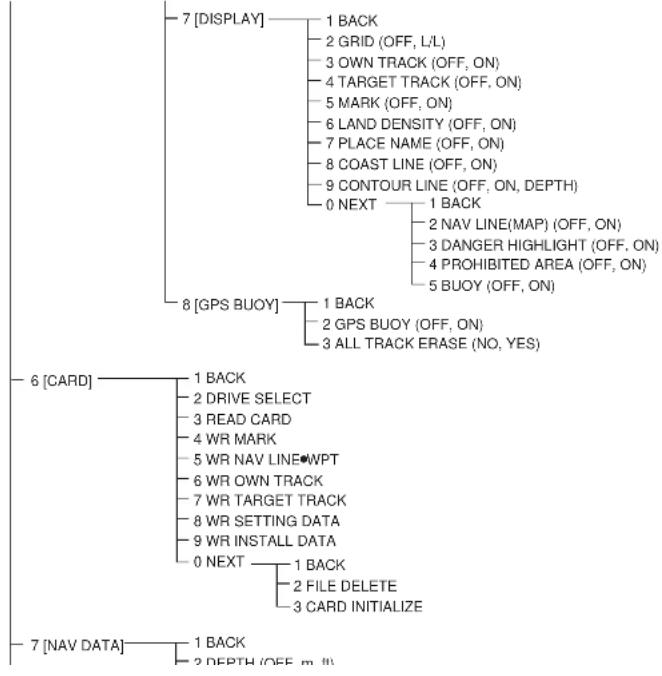
flowchart
graph TD
    A["7 [DISPLAY"]] --> B["1 BACK"]
    A --> C["2 GRID (OFF, L/L)"]
    A --> D["3 OWN TRACK (OFF, ON)"]
    A --> E["4 TARGET TRACK (OFF, ON)"]
    A --> F["5 MARK (OFF, ON)"]
    A --> G["6 LAND DENSITY (OFF, ON)"]
    A --> H["7 PLACE NAME (OFF, ON)"]
    A --> I["8 COAST LINE (OFF, ON)"]
    A --> J["9 CONTOUR LINE (OFF, ON, DEPTH)"]
    A --> K["0 NEXT"] --> L["1 BACK"]
    L --> M["2 NAV LINE(MAP) (OFF, ON)"]
    L --> N["3 DANGER HIGHLIGHT (OFF, ON)"]
    L --> O["4 PROHIBITED AREA (OFF, ON)"]
    L --> P["5 BUOY (OFF, ON)"]
    A --> Q["8 [GPS BUOY"]] --> R["1 BACK"]
    Q --> S["2 GPS BUOY (OFF, ON)"]
    Q --> T["3 ALL TRACK ERASE (NO, YES)"]
    U["6 [CARD"]] --> V["1 BACK"]
    U --> W["2 DRIVE SELECT"]
    U --> X["3 READ CARD"]
    U --> Y["4 WR MARK"]
    U --> Z["5 WR NAV LINEWPT"]
    U --> AA["6 WR OWN TRACK"]
    U --> AB["7 WR TARGET TRACK"]
    U --> AC["8 WR SETTING DATA"]
    U --> AD["9 WR INSTALL DATA"]
    U --> AE["0 NEXT"] --> AF["1 BACK"]
    AF --> AG["2 FILE DELETE"]
    AF --> AH["3 CARD INITIALIZE"]
    AI["7 [NAV DATA"]] --> AJ["1 BACK"]
    AI --> AK["2 DEPTH (OFF, m, II)"]
(Continued from previous page)
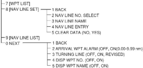
flowchart
graph TD
    A["7 [WPT LIST"]] --> B["8 [NAV LINE SET"]]
    B --> C["9 [NAV LINE LIST"]]
    C --> D["0 NEXT"]
    B --> E["1 BACK"]
    B --> F["2 NAV LINE NO. SELECT"]
    B --> G["3 NAV LINE NAME"]
    B --> H["4 NAV LINE ENTRY"]
    B --> I["5 CLEAR DATA (NO, YES)"]
    C --> J["1 BACK"]
    C --> K["2 ARRIVAL WPT ALARM (OFF, ON(0.00-9.99 nm))"]
    C --> L["3 TURNING LINE (OFF, ON, REVISED)"]
    C --> M["4 DISP WPT NO. (OFF, ON)"]
    C --> N["5 DISP WPT NAME (OFF, ON)"]
![9 [CUSTOMIZE TEST] 1 BACK 2 [DATA BOX] 1 BACK 3 NAV DATA (OFF, ON) 4 ZOOM (OFF, 2TIMES, 3TIMES) 5 ZOOM DISPLAY (STAB GND, STAB HDG, STAB NORTH, ARP TRACK) 6 TARGET DATA (1BOX, 2BOX, 3BOX, LARGE) 3 [F1] 1 PICTURE 2 IR 3 ES 4 EAV 5 PULSE LENGTH 6 WIPER 7 ECHO AREA 8 NO FUNCTION 9 NO FUNCTION 0 NO FUNCTION 4 [F2] 1 OS TRAIL 2 BRILL 3 DISP ARP 4 DISP AIS 5 DISPLAY SELECT](/content/2026/05/925548/images/2fb2f975b1b75d31c4326c8d2e78d35017bbe54292d6a15e9f20efa09654c61c.jpg)
(Continued from previous page)
![1 BACK 2 [ECHO] 1 BACK 2 (PICTURE, IR, ES, EAV, NOISE REJ, ANT SELECT, PULSE LENGTH, A/C SEA SELECT, AUTO RAIN SELECT, TUNE SELECT, VIDEO CONTRAST, VIDEO CONTRAST 2, ANT HEIGHT, SEA CONDITION, 2ND ECHO REJ, PM, SART, WIPER, ECHO AREA) 3 [STD KEY] 1 BACK 2 (ALARM ACK, STBY TX, HL OFF, MODE, OFF CENTER, CU TM RESET, INDEX LINE. VECTOR TIME, VECTOR MODE, TARGET LIST, TRAIL TIME, TRAIL GRAD, OS TRAIL, BRILL, MENU, RANGE UP, RANGE DOWN, ACQ, TARGET DATA. TARGET CANCEL) 4 [ARP/AIS] 1 BACK 2 (DISP ARP. DISP AIS, TARGET DATA & ACQ, PAST POSN INTERVAL, REF MARK, CPA LIMIT, CPA, TCPA, TARGET LIST SORT, TRIAL MANEUVER, ARP/AIS, FUSION, ARP SYMBOL COLOR, ARP SYMBOL SIZE, ARP PAST COLOR, ARP PAST POINTS, AIS MESSAGE, AIS SYMBOL COLOR, AIS SYMBOL SIZE, AIS PAST COLOR, AIS PAST POINTS, TRIAL MODE CHANGE) 5 [OPERATION] 1 BACK 2 (ECHO COLOR, BACK COLOR, RING, WATCH ALARM RESET, ZOOM, DISPLAY SELECT, RADAR COMBINE, MOB, USER DEFAULT, TLL, ANCHOR WATCH, COLOR SHIFT, ICON DISP, OWN TRACK ALL ERASE, TGT TRACK ALL ERASE) 6 [PICTURE] 1 BACK 2 (PICTURE1, PICTURE 2, PICTURE 3, PICTURE 4, NEAR, FAR, NEAR BUOY, FAR BUOY, ROUGH SEA, SHIP, NEAR BIRD, FAR BIRD) 7 [MARK] 1 BACK 2 (OWN SHIP MARK, STERN MARK, INDEX LINE, INDEX LINE MODE. EBL OFFSET BASE. EBL1 BEARING. EBL2](/content/2026/05/925548/images/0c9c85d0c1fde1cd5f38828bcaeeddf9fcf476bc134a031d4bb4fe768b07c984.jpg)
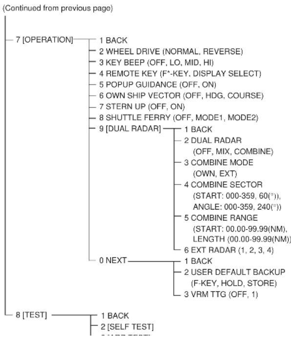
flowchart
graph TD
    A["7 [OPERATION"]] --> B["1 BACK"]
    A --> C["2 WHEEL DRIVE (NORMAL, REVERSE)"]
    A --> D["3 KEY BEEP (OFF, LO, MID, HI)"]
    A --> E["4 REMOTE KEY (F*-KEY, DISPLAY SELECT)"]
    A --> F["5 POPUP GUIDANCE (OFF, ON)"]
    A --> G["6 OWN SHIP VECTOR (OFF, HDG, COURSE)"]
    A --> H["7 STERN UP (OFF, ON)"]
    A --> I["8 SHUTTLE FERRY (OFF, MODE1, MODE2)"]
    A --> J["9 [DUAL RADAR"]]
    J --> K["1 BACK"]
    J --> L["2 DUAL RADAR (OFF, MIX, COMBINE)"]
    J --> M["3 COMBINE MODE (OWN, EXT)"]
    J --> N["4 COMBINE SECTOR (START: 000-359, 60(°)), ANGLE: 000-359, 240(°))"]
    J --> O["5 COMBINE RANGE (START: 00.00-99.99(NM), LENGTH (00.00-99.99(NM))"]
    J --> P["6 EXT RADAR (1, 2, 3, 4)"]
    J --> Q["1 BACK"]
    J --> R["2 USER DEFAULT BACKUP (F-KEY, HOLD, STORE)"]
    J --> S["3 VRM TTG (OFF, 1)"]
    T["8 [TEST"]] --> U["1 BACK"]
    T --> V["2 [SELF TEST"]]
Pop-up menus (access by
[HDG MENU]
1 HDG SOURCE AD-10/SERIAL 2 GO-10 SETTING 000.0°
HDG menu
[SPD MENU]
1 SHIP SPEED LOG(BT)/LOG(WT) GPS/MANUAL/REF 2 MANUAL SPEED
3 SET DRIFT OFF/ON
SPEED menu
[CURSOR MENU]
2 ↓ TARGET DATA & ACQ/ TARGET CANCEL/ ARP TGT DATA & ACQ/ TARGET TRACK ON/ TARGET TRACK OFF/ REF MARK
OFFCENTER/ ZOOM
OWN TRACK DELETE/TGT TRACK DELETE/CHART ALIGN/TRAIL ERASER
B ↑ 9 CURSOR SIZE SMALL/LARGE
CURSOR menu
[OS POSN MENU]
1 NAV AID GPS1/GPS2/ DEAD RECKONING/ LAN 2 MANUAL L/L 00'00.000 N 000'00.000 W 3 SIO DATA LAN OUTP OFF/ON
OS POSN menu
[ARP TARGET MENU]
1 ARP SELECT MANUAL 100/ AUTO 25/ AUTO 50/ AUTO 75/ AUTO 100
2 ALL CANCEL NO/YES 3 REF TARGET VECTOR
ARP TARGET menu
[AIS TARGET MENU]
1 SLEEP ALL TRGTS NO/YES 2 ACTIVATE ALL TRGTS NO/YES 3 AUTO DISP MESSAGES OFF/ON 4 [RECEIVED MESSAGES] 5 [TRANSMIT MESSAGE] 6 [VOYAGE DATA] 7 [STATIC DATA] 8 [AIS ALM MESSAGES]
AIS TARGET menu
[TRANSMIT MESSAGE]
1 BACK 2 ADDRESS TYPE ADDRESSED/BROADCAST 3 MESSAGE TYPE SAFETY/BINARY 4 MMSI NO. 000000000 5 CHANNEL
A/B/A or B/A and B • OPEN FILE
[VOYAGE DATA]
1 BACK 2 NAVIGATION STATUS 00 UNDERWAY USING ENGINE 3 ETA 00/000/0000 00:00 4 DESTINATION
5 DRAUGHT
[STATIC DATA]
1 BACK TYPE OF SHIP 00 ALL SHIPS OF THIS TYPE CALL SIGN NAME
EXT GPS ANT POSN
![[BRILL1 MENU (1/2)] 1 ECHO COLOR YEL/GRN/ WHT/COLOR 2 BKGD COLOR BLK-GRN/ BLK-RED/ BLU-CIR/ BLUBRT-BLU 3 PANEL DIMMER 4 CHARACTER 5 CURSOR 6 ECHO 7 TRAIL 8 HL 9 RING 0 NEXT [BRILL1 MENU (2/2)] 1 BACK 2 BRG CURSOR 3 EBL 4 VRM 5 INDEX LINE 6 ARP SYMBOL 7 AIS SYMBOL 8 L/L GRID 9 MARK 0 CHART BRILL menu, page 2](/content/2026/05/925548/images/0f6d8f889913885584af7ba9db4cf556d6f281f28c73c39cb593574a02db0eeb.jpg)
BRILL menu, page 1
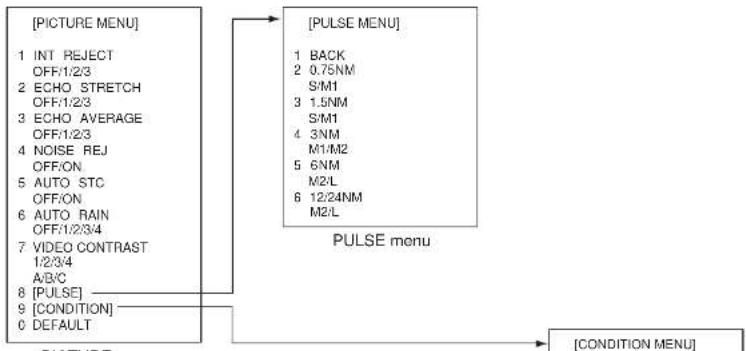
flowchart
graph TD
    A["[PICTURE MENU"]] --> B["[PULSE MENU"]]
    B --> C["[CONDITION MENU"]]
    subgraph PULSE Menu
        D["1 BACK"] --> E["2 0.75NM"]
        E --> F["S/M1"]
        F --> G["3 1.5NM"]
        G --> H["S/M1"]
        H --> I["4 3NM"]
        I --> J["M1/M2"]
        J --> K["5 6NM"]
        K --> L["M2/L"]
        L --> M["6 12/24NM"]
        M --> N["M2/L"]
    end
    D --> O["1 INT REJECT OFF/1/2/3"]
    D --> P["2 ECHO STRETCH OFF/1/2/3"]
    D --> Q["3 ECHO AVERAGE OFF/1/2/3"]
    D --> R["4 NOISE REJ OFF/ON"]
    D --> S["5 AUTO STC OFF/ON"]
    D --> T["6 AUTO RAIN OFF/1/2/3/4"]
    D --> U["7 VIDEO CONTRAST 1/2/3/4"]
    D --> V["A/B/C"]
    D --> W["8 [PULSE"]]
    D --> X["9 [CONDITION"]]
    D --> Y["0 DEFAULT"]
    W --> Z["PICTURE"]
    X --> AA["PICTURE"]
    Y --> AB["PICTURE"]
    Z --> AC["PULSE menu"]
    AA --> AC
    AB --> AC

(Elemental Chlorine Free)
The paper used in this manual is elemental chlorine free.
- Fishing Vessel Specifications
- Contents
- TARGET TRAIL FUNCTIONS
- Long Trails
- [TRAIL MENU]
- Trail Color
- Trail Color Shift
- Hiding Trails
- Trail Eraser
- Narrow Trails
- Preventing True Sea Clutter Trails
- CURSORS
- Crosshairs Cursor Size
- Net Cursor
- Activating the net cursor
- Setting net cursor dimensions, adjusting net cursor orientation
- Cursor Data Display
- Bearing Scale Format
- OTHER FUNCTIONS
- Echo Display Area
- Turning On-screen Boxes On/Off
- Radar Picture Color
- Bearing Reference
- VRM, Cursor Unit
- Pop-up Guidance
- FUNCTION KEYS (F1 - F4)
- F1, F2 and F3 Keys
- Operating F1, F2 and F3 keys
- Programming the F1, F2 and F3 keys
- [F1-1-ECHO]
- [F1-1-STD KEY]
- [F1-1-ARP-AIS]
- [F1-1-OPERATION]
- [F1-1-PICTURE]
- [F1-1-MARK]
- [F1-1-PLOTTER]
- [F1-1-NAV LINEWPT]
- Operating the F4 Key
- Registering a program to the F4 key
- Operating the F4 key
- ANCHOR WATCH ALARM
- VIDEO PLOTTER FUNCTIONS
- Depth Contour with Depth Indication
- Mark Settings
- Enabling, disabling mark comment input and mark position editing
- Entering mark comment, changing mark position
- Selecting mark color
- Track Settings
- Track recording interval
- [PLOTTER]
- [OWN TRACK]
- [TGT TRACK]
- Changing track color
- Changing the color of your ship's track
- Changing the color of target tracks
- Erasing track with the cursor
- Selecting erasure method
- Erasing track between two points, area
- Erasing all track of a target
- GPS Buoy
- Enabling, disabling GPS buoy information
- ARP SYMBOLS
- DISPLAYING PICTURE FROM EXTERNAL RADAR
- MENU OVERVIEW
- Pop-up menus (access by
Brand : FURUNO
Model : FAR-2107
Category : Marine Electronics