
LA11 - Marine Electronics FURUNO - Free user manual and instructions
Find the device manual for free LA11 FURUNO in PDF.


| Product Type | Hydraulic Linear Actuator for Autopilot Integration |
| Model | LA11 |
| Voltage Options | 12 VDC (LA11-12) or 24 VDC (LA11-24) |
| Pump Output Flow | 1.0 cu in/sec (16.4 cc/sec) |
| Average Motor Current (12V) | 3-6 Amps |
| Average Motor Current (24V) | 2-4 Amps |
| Solenoid Valve Current (12V) | 1.5 Amps |
| Solenoid Valve Current (24V) | 0.75 Amps |
| Weight | 15 lbs (7 kg) |
| Cylinder Bore | 1.5 inches |
| Cylinder Stroke | 9 inches |
| Cylinder Volume | 13.1 cu in (215 cc) |
| Maximum Thrust | Approx. 785 lbs at 500 psi |
| Torque (at 6" tiller arm) | 4,710 in/lb |
| Oil Type | ISO-32 Hydraulic Oil |
| Reservoir Capacity | 11.5 cu in |
| Bypass Valve | Normally Open Solenoid, Closes When Energized |
| Motor Protection | Ignition Protected (UL 1500, SAE-1171) |
| Mounting | Horizontal shelf or bracket with anti-vibration mounts |
| Rudder Speed (HOH) | Approx. 13 seconds (hard over to hard over) |
Frequently Asked Questions - LA11 FURUNO
User questions about LA11 FURUNO
0 question about this device. Answer the ones you know or ask your own.
Ask a new question about this device
Download the instructions for your Marine Electronics in PDF format for free! Find your manual LA11 - FURUNO and take your electronic device back in hand. On this page are published all the documents necessary for the use of your device. LA11 by FURUNO.
USER MANUAL LA11 FURUNO
Defining Reliability
through form and function.
(Each unit is completely tested after assembly)
Dedicated to quality high-performance hydraulic control of steering systems for yachts and commercial vessels.
Instruction Manual
LA11
natural_image
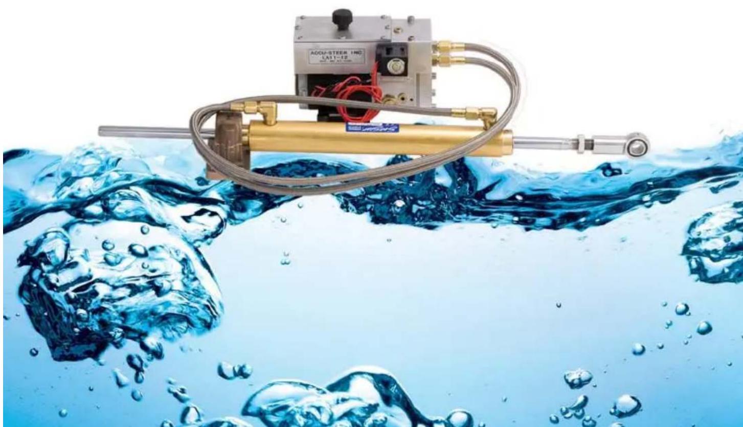
Industrial hydraulic controller with coiled tubing submerged in blue water, creating bubbles (no text or symbols visible)3.3 Reservoir/Bypass Assembly
3.4 Steering Cylinder
- INSTALLATION ...... p. 05
4.1 Mechanical
4.2 Hydraulic
4.3 Electrical
5. NOTES ...... p. 07
6. DRAWINGS ...... p. 08
6.1 LA11 — Assembly Schematic
6.2 LA11 — System Connection Schematic
1. GENERAL INFORMATION
The Accu-Steer LA11 unit is a hydraulic linear actuator designed to interface an autopilot system with a mechanical steering systems such as wire, cable or chain drives. A hydraulic linear actuator consists of a hydraulic drive unit (containing a pump unit, bypass valve and reservoir assembly), a steering cylinder and the interconnecting hoses.
One end of the cylinder is fixed and the other end is connected to a tiller arm or the mechanical quadrant, which is connected to a rudder shaft. With this connection to a tiller arm the linear movement of the cylinder is changed to rotary movement, which turns the rudder and steers the vessel.
During normal mechanical steering, the hydraulic steering cylinder strokes to port and starboard as the vessel is steered manually. The oil in both sides of the cylinder flows back and forth through a normally open bypass valve located in the linear actuator drive unit. The steering cylinder is connected to the drive assembly with two hoses (port and starboard). When the autopilot is switched into the operating mode, the bypass valve is electrically closed. The autopilot then drives the reversing hydraulic pump which in turn operates the steering cylinder. See section 3 of this manual for a more in depth description.
When the autopilot is operating, the cylinder with be turning the rudder. The mechanical steering will be back-driven during this time. The vessel's steering wheel will be turning as the autopilot makes corrections.
The Accu-Steer HRP11 is the reversing pump unit used in the LA11 linear actuator. The output flow rate of the pumpset determines the speed of the steering cylinder. The HRP11 pump outputs 1.0 cu in/sec or 16.4 cc/sec.
The BA150 X 9 is a balanced steering cylinder, which means the volume of oil on both sides of the cylinder is equal. The volume of this steering cylinder is 13 cu in (215 cc) of oil.
2. TECHNICAL SPECIFICATIONS and APPLICATION
| Model Number LA11-12 LA11-24 | |
| Voltage 12 VDC 24 VDC | |
| Output/Sec 1 cu in/sec 1.0 cu in/sec | |
| Average Motor Amp 3-6 2-4 | |
| Solenoid Valve Amp 1.5 AMPS .75 AMP | |
| Weight 15 lbs (7 kgs) 15 lbs (7 kgs) |
The output of the hydraulic reversing pump is 1.0 cu in/sec. The volume of the steering cylinder is approximately 13.1 cu in (215 cubic centimeters). The rudder speed will be approximately 13 seconds hard over to hard over (HOH).
The rudder speed, hard over to hard over (HOH), is determined by dividing the volume (cu in) of the cylinder by the output of the pumpset (cu in/sec).
The steering cylinder is capable of approximately 785 lbs of thrust based on an output of 500 psi from the pump. The force or torque applied to the rudder through the rudder shaft is dependent of the distance between the center of the rudder shaft and the position of the tiller bolt.
Figure 2 CYLINDER SCHEMATIC
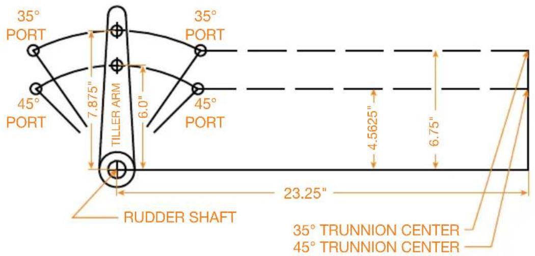
Distance (rudder shaft to tiller bolt): 6" = 4,710 in/lb; 7" = 5,495 in/lb; 8" = 6,280 in/lb; 9" = 7,065 in/lb. The torque required to turn the rudder can be calculated or obtained from the vessel's builder.
3. DESCRIPTION OF OPERATION
3.1 GENERAL
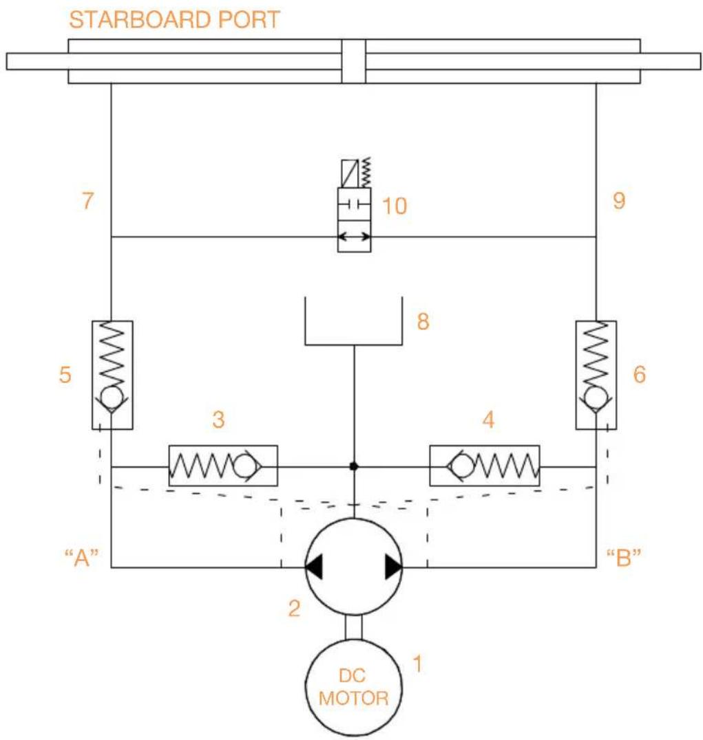
The Accu-Steer LA11 is a complete linear actuator drive unit. It consists of a reversing gerotor gear pump, hydraulic lock valves, suction make-up check valves, a valve housing manifold, an electric permanent magnet motor, an electric solenoid bypass valve and an oil reservoir.
Figure 3.1 HYDRAULIC SCHEMATIC
flowchart
graph TD
    A["STARBOARD PORT"] --> B["7"]
    B --> C["10"]
    C --> D["9"]
    D --> E["5"]
    E --> F["3"]
    F --> G["4"]
    G --> H["6"]
    H --> I["B"]
    I --> J["2"]
    J --> K["DC MOTOR 1"]
    style A fill:#f9f,stroke:#333
    style B fill:#ccf,stroke:#333
    style C fill:#cfc,stroke:#333
    style D fill:#fcc,stroke:#333
    style E fill:#cff,stroke:#333
    style F fill:#ffc,stroke:#333
    style G fill:#cfc,stroke:#333
    style H fill:#fcc,stroke:#333
    style I fill:#ffc,stroke:#333
    style J fill:#cfc,stroke:#333
    style K fill:#fcc,stroke:#333
During normal mechanical steering the cylinder is stroked both ways as driven by the mechanical steering system. The oil in the cylinder is bypass through the normally open (NO) solenoid valve (10). When the autopilot becomes active it closes the solenoid valve (clutch/bypass or switched power output). The autopilot then drives the hydraulic reversing pump (2).
The HRP (Hydraulic Reversing Pumpset) operates as follows:
As the motor (1) rotates CCW, oil from the gear pump (2) is pumped towards output “A”. This oil passes through the check valve (5) and goes to the line output (7). The oil pushes the cylinder in the port direction. The pressure at output “A” ensures the check valve (3) stays closed and manually opens check valve (6). Opening check valve (6) allows the returning oil from the steering cylinder to flow back to the pump. If the pressure at the pump suction “B” is less than the weight of the oil in the reservoir (8) then the oil in the reservoir will pass by the check valve (4). This prevents cavitation due to any air that may be in the steering line. When the pump stops turning all spring-loaded check valves return to the normally closed position. When the motor (1) rotates (CW) the reverse movement of the oil and valves takes place.
3.2 PUMP UNIT (HRP11)
The electric motor has the following features:
- Ignition protected (UL 1500 and SAE-1171)
• Ball bearing shaft supports both ends
• Cushioned foot mounts for quiet operation
• Opposite end shaft mount for tachometer/encoder
The valve block is an aluminum block, precision machined to house the valves, direct the oil and serve as the endplate for the gear pump. The output check valves are part of what is called a lockvalve assembly.
The lockvalve assembly consists of two output check valves and a lockvalve spool. In the non-running position the spring operated check valves remain closed, isolating the pump from the steering system. The spring action of the check valves holds the lockvalve spool in the mid-closed position.
3.3 RESERVOIR/BYPASS ASSEMBLY
The reservoir unit is machined out of solid aluminum and provides approximately 11.5 cu in of oil for oil make-up. The solenoid bypass valve is located in the same aluminum housing. It is a normally open valve and switches to the closed position when energized by the autopilot. The valve returns to the normally open position when the autopilot is switched into the standby mode or if there was a loss of power to the autopilot.
Oil passages are machined as large as possible to minimize any restrictions which may effect manual steering.
3.4 STEERING CYLINDER
The brass steering cylinder is engineered and manufactured for heavy duty marine usage and is suitable for commercial and pleasure boat applications. The cylinder has a 1-1/2" bore and a 9" stroke. The trunnion mount (fixed end) and the ball joint allow for about 10 degrees of articulation. The cylinder is shipped full of oil and is also equipped with bleed fittings.
4. INSTALLATION
4.1 MECHANICAL
The linear actuator drive unit must be mounted on a horizontal shelf or bracket with a solid foundation. The unit can be bolted or screwed down with the motor feet and the foot bracket. The mounting brackets are fitted with anti-vibration mounts to maintain the quiet operation of the pumpset. The drive unit should be mounted above the steering cylinder if possible to assist in the system bleeding.
Proper cylinder installation is the key to the successful operation of the linear actuator. An incorrectly installed cylinder is subject to rapid seal and bearing wear and non-repairable damage. Minimum side loading of the cylinder rod and maximum cylinder performance can be achieved as follows.
An imaginary line drawn through the tiller arm hole at both hard over positions will create the cylinder center line, see Figure 4.1. The distance between X and Y must be less than 9" so that the cylinder doesn't act as an end stop for the rudder.
Figure 4.1 CYLINDER SCHEMATIC
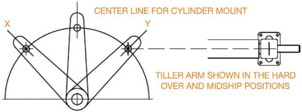
In a new installation, mechanical stops can be installed after the cylinder. For retro-fit applications, use Figure 4.1 as a reference to ensure the ends of the cylinder travel are outside the stops. Mount cylinder with the fittings in the up direction.
4.2 HYDRAULIC
The unit is shipped full of oil with a sealed plug in the top of the reservoir cover. A vented breather cap is supplied with the unit. The vented cap must be installed in place of the plug after the drive unit has been mounted. The oil in the LA11 is standard hydraulic oil (ISO-32).
If the hydraulic lines are removed during installation, be sure to cap them to minimize the loss of oil. Located on the top of the valve/reservoir block is a small bleed fitting. This fitting can be used add oil to the port and starboard lines or bleed air from the system. If the cylinder is mounted properly, the cylinder can be manually stroked and the air will collect at the bleed fitting. Be sure to re-install this plug before using the LA11 as it is part of the steering line.
The oil reservoir should be maintained at least 3/4 full. During bleeding and filling this level should be maintained.
It is not critical to identify which of the steering lines is port or starboard as most new autopilots will determine the pump direction and program the drive outputs to suit. For older autopilots the motor leads can be reversed to change the pumps direction.
4.3 ELECTRICAL
The motor is a permanent magnet style motor, ignition protected, built to conform to UL-1500 and SAE-1171 standards. Two leads connect to the autopilot pump driver junction box (processor), the direction of the pumpset can be reversed by simply reversing the polarity of these two leads.
The solenoid valve is connected to the autopilot junction box. It is usually referred to as clutch/bypass or switched power. The polarity of the solenoid valve does not matter.
To test the operation of the LA11 pumpset, touch the two leads from the motor to the supply voltage (12 VDC or 24 VDC) to jog the motor in one direction and then reverse the leads to jog the pumpset in the other direction. Do not to perform this operation where any combustible fumes exist.
5. NOTES
6. DRAWINGS
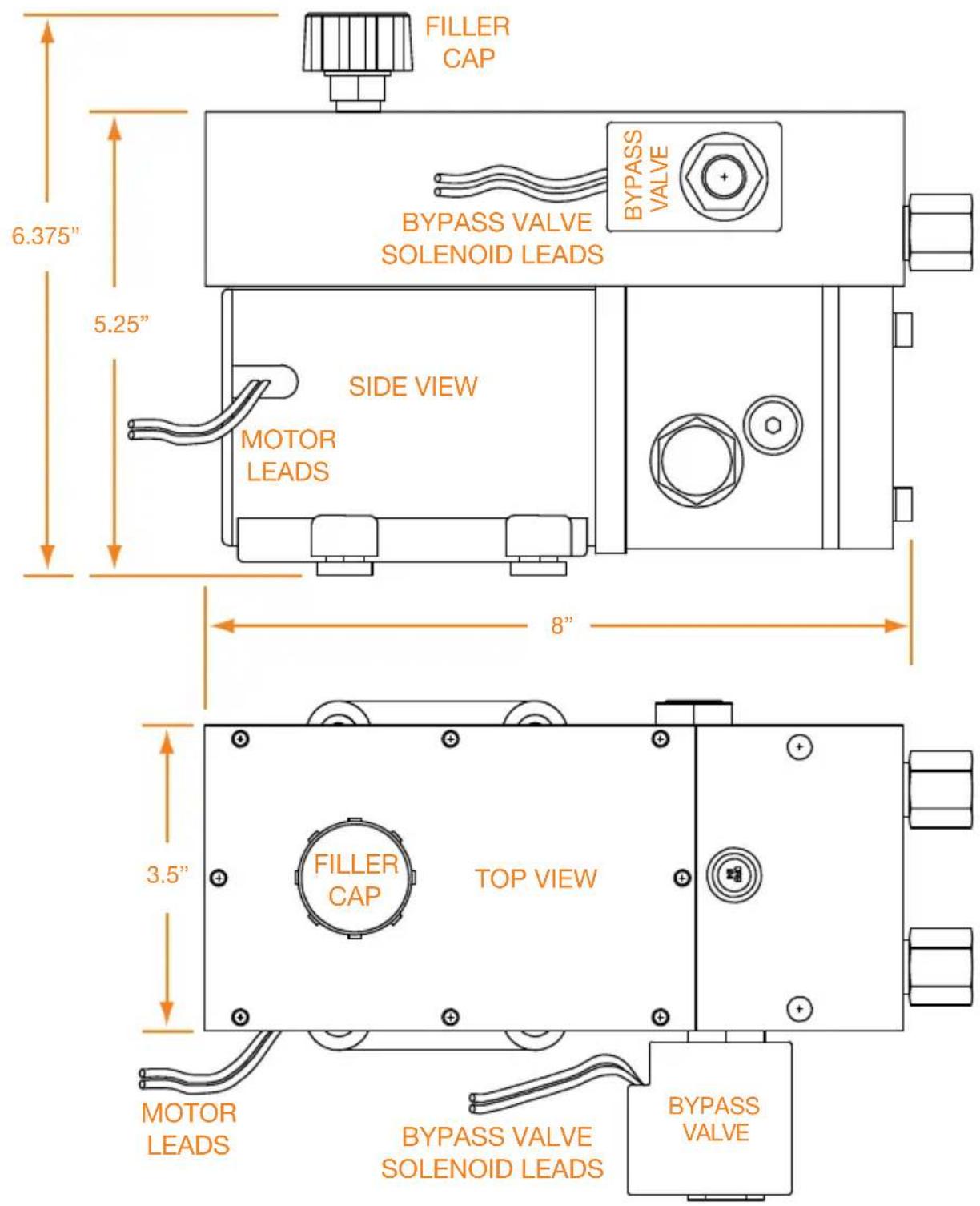
6.1 LA11 ASSEMBLY SCHEMATIC
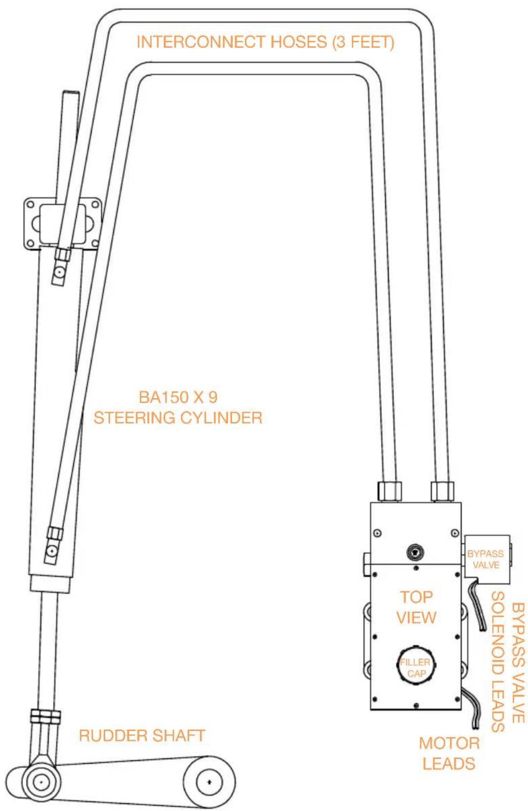
6.2 LA11 SYSTEM CONNECTION SCHEMATIC
natural_image
Abstract water splash pattern with blue and white gradients (no text or symbols)STAYING TRUE TO YOUR COURSE.
Accu-Steer, Inc.
Accu-Steer, Inc. • Marina Square 704 Coho Way • Bellingham, WA 98225
(360) 733-4565, telephone • (360) 733-4575, fax
cs@Accu-Steer.com • www.Accu-Steer.com
Instruction Manual
LA11
- Defining Reliability
- Instruction Manual
- LA11
- GENERAL INFORMATION
- TECHNICAL SPECIFICATIONS and APPLICATION
- DESCRIPTION OF OPERATION
- GENERAL
- PUMP UNIT (HRP11)
- RESERVOIR/BYPASS ASSEMBLY
- STEERING CYLINDER
- INSTALLATION
- MECHANICAL
- HYDRAULIC
- ELECTRICAL
- NOTES
- DRAWINGS
- LA11 ASSEMBLY SCHEMATIC
- LA11 SYSTEM CONNECTION SCHEMATIC
Brand : FURUNO
Model : LA11
Category : Marine Electronics