
FAX-408 - Marine Electronics FURUNO - Free user manual and instructions
Find the device manual for free FAX-408 FURUNO in PDF.


| Product Type | Marine Facsimile Receiver |
| Model | FAX-408 |
| Brand | Furuno |
| Frequency Range | 2.0000 - 24.99999 MHz (MF/HF) |
| Reception Mode | F3C (FM facsimile) |
| Selectivity | 2.0 kHz at -6 dB |
| Number of Channels | 314 (150 preset + 164 user-programmable) |
| Sensitivity | 2 µV at 20 dB SINAD |
| Recording System | Electronic scanning with thermal head |
| IOC (Index of Cooperation) | 576 and 288 |
| Recording Speed | 60, 90, 120 scans per minute |
| Gradation | 9 tones (white, 7 gray levels, black) |
| Recording Paper | Thermal paper, 216 mm × 20 m roll |
| Line Density | 8 dots/mm (1696 dots total) |
| Display | LCD, 32 characters × 2 lines |
| Tuning Indicator | 3 LEDs (red/green) |
| Power Supply | 12/24 VDC (negative ground) |
| Power Consumption | Approx. 30 W |
| Dimensions (Main Unit) | Approx. 352 (W) × 141 (H) × 346 (D) mm |
| Weight (Main Unit) | Approx. 6.5 kg |
| Antenna | Whip (2.6 m or 6 m) or wire (≥10 m) |
| Preamp Unit (Optional) | FAX-5, for weak signal conditions |
| External Receiver Input | Ext AF IN, >50 mV, FSK or FM |
| Battery Backup | CR-2032 lithium cell (approx. 5 years life) |
| Fuse | FGBO 125V 7A PBF |
| Languages | English, Dutch, Finnish, Norwegian, Swedish, Danish, Portuguese, Italian, German, Spanish, French |
Frequently Asked Questions - FAX-408 FURUNO
User questions about FAX-408 FURUNO
0 question about this device. Answer the ones you know or ask your own.
Ask a new question about this device
Download the instructions for your Marine Electronics in PDF format for free! Find your manual FAX-408 - FURUNO and take your electronic device back in hand. On this page are published all the documents necessary for the use of your device. FAX-408 by FURUNO.
USER MANUAL FAX-408 FURUNO
The paper used in this manual is elemental chlorine free.
IMPORTANT NOTICES
- This manual is intended for use by native speakers of English.
- No part of this manual may be copied or reproduced without written permission.
- If this manual is lost or worn, contact your dealer about replacement.
- The contents of this manual and equipment specifications are subject to change without notice.
- The example screens (or illustrations) shown in this manual may not match the screens you see on your display. The screen you see depends on your system configuration and equipment settings.
- Store this manual in a convenient place for future reference.
- FURUNO will assume no responsibility for the damage caused by improper use or modification of the equipment by an unauthorized agent or a third party.
- Dispose of the equipment in accordance with appropriate regulations.

SAFETY INSTRUCTIONS
The user and installer must read the appropriate safety instructions before attempting to install or operate the equipment.

WARNING
Indicates a potentially hazardous situation which, if not avoided, could result in death or serious injury.

CAUTION
Indicates a potentially hazardous situation which, if not avoided, may result in minor or moderate injury.

Warning, Caution

Prohibitive Action

Mandatory Action
Safety Instructions for the Operator

WARNING

Do not open the equipment except to replace paper.
Only qualified personnel should work inside the equipment.

Immediately turn off the power at the switchboard if water leaks into the equipment or something is dropped into the equipment.

WARNING

Make sure no rain or water splash leaks into the equipment.
Fire or electrical shock can result if water leaks in the equipment.

Use the proper fuse.
Use of a wrong fuse can result in damage to the equipment or cause fire.

CAUTION

Do not use commercial cleaners to clean the main unit.
Commercial cleaners may remove paint and markings. Remove dust from the main unit with a soft cloth. For stubborn dirt, use water-diluted mild detergent and a soft cloth.
WARNING LABEL
A warning label is attached to the main unit. Do not remove the label. If the label is missing or damaged, contact a FURUNO agent or dealer about replacement.
| WARNING | |
| To avoid electrical shock, do not remove cover. No user-serviceable parts inside. | |
Name: Warning Label 1
Type: 86-003-1011-2
Code No.: 100-236-232-10
Safety Instructions for the Installer

WARNING

Turn off the power at the switchboard before beginning the installation.
Fire or electrical shock can result if the power is left on.

CAUTION

Observe the following compass safe distances to prevent interference to a compass:
| Standard compass | Steering compass | |
| Facsimile Receiver | 0.7 m | 0.5 m |

Observe the following cautions when
TABLE OF CONTENTS
FOREWORD......vi
EQUIPMENT LIST ......vii
SYSTEM CONFIGURATION......viii
- OPERATION....1
1.1 Control Description....1
1.2 Turning the Power On/Off....3
1.3 Adjusting LCD Contrast 3
1.4 Adjusting LCD Brilliance and LED Brightness 3
1.5 Channel and Frequency Displays....3
1.5.1 Channel setting....3
1.5.2 Selection of desired frequency, fine adjustment of frequency....4
1.6 Automatic Receiving....4
1.7 Manual Receiving 5
1.8 Timer Receiving....5
1.8.1 Registering timer programs ....5
1.8.2 Choosing timer programs for timer reception 6
1.8.3 Disabling timer operation when awaiting reception ....7
1.8.4 Unlocking the keyboard during timer reception 7
1.8.5 Confirming timer programs....7
1.9 Processing Facsimile Images....8
1.9.1 Speed and IOC....8
1.9.2 Manual phasing 9
1.9.3 Synchronization....9
1.9.4 Reverse mode 9
1.10 Sleep Timer 10
1.10.1 Activating the sleep timer 10
1.10.2 Unlocking the keyboard....10
1.10.3 Disabling the sleep timer .... 10
3. INSTALLATION....21
3.1 Main Unit 21
3.2 Antenna 22
3.2.1 General antenna connection.... 22
3.2.2 Whip or wire antenna 23
3.2.3 Installation of optional preamp unit (FAX-5).... 23
3.3 Wiring 24
3.3.1 Power, ground.... 24
3.3.2 External equipment 24
3.3.3 Whip or wire antenna 25
3.3.4 Setting of SW S1 on RCV board (when preamp unit is used).... 26
3.4 Changing Display Language....27
FACSIMILE STATION TABLES 29
SPECIFICATIONS.... SP-1
PACKING LIST......A-1
OUTLINE DRAWINGS ....D-1
INTERCONNECTION DIAGRAM....S-1
FOREWORD
A Word to the Owner of the FAX-408
FURUNO Electric Company thanks you for purchasing the FURUNO FAX-408 Facsimile Receiver. We are confident you will discover why the FURUNO name has become synonymous with quality and reliability.
For over 50 years FURUNO Electric Company has enjoyed an enviable reputation for quality and reliability throughout the world. This dedication to excellence is furthered by our extensive global network of agents and dealers.
Your equipment is designed and constructed to meet the rigorous demands of the marine environment. However, no machine can perform its intended function unless properly installed and maintained. Please carefully read and follow the operation, installation and maintenance procedures set forth in this manual.
We would appreciate feedback from you, the end-user, about whether we are achieving our purposes.
Thank you for considering and purchasing FURUNO.
Features
The FAX-408 uses an Individual scanning recording thermal head to produce high quality facsimile images.
- Electronic scanning with thermal head recording system provides clear image, quiet operation.
EQUIPMENT LIST
Standard supply
| Name Type Code No. Qty Remarks | ||||
| Facsimile Receiver FAX-408 — 1 | ||||
| Installation Materials CP08-02101 000-163-087 1 set See the Packing Lists atthe end of this manual. | ||||
| Accessories FP08-01000 000-163-088 1 set | ||||
| Spare Parts | SP08-02301 | 000-163-082 1 set | ||
Optional supply
| Name | Type | Code No. | Remarks |
| Preamp Unit | FAX-5 | 000-075-016 | w/15 m cable |
| FAX-5 | 000-075-049 | w/1 m cable | |
| Whip Antenna | 04S4176 | 000-153-122 | 2.6 m, for use with FAX-5 |
| FAW-6R2 000-57 | 2-108 6 m | ||
| FAW-6R2A | 000-107-921 | 6 m, w/mounting bracket | |
| Hose Clamp | OP08-11 | 005-946-960 | For mounting preamp unit |
| Matching Box | ARD-1 | 005-502-230 | |
| Antenna Cable Extension Kit | OP04-2 *10M* 000-041-174 | 10 m, 3D-2V, w/MP3 connector at both ends | |
| OP04-2 *20M* 000-041-175 | 20 m, 3D-2V, w/MP3 connector at both ends | ||
1.1 Control Description
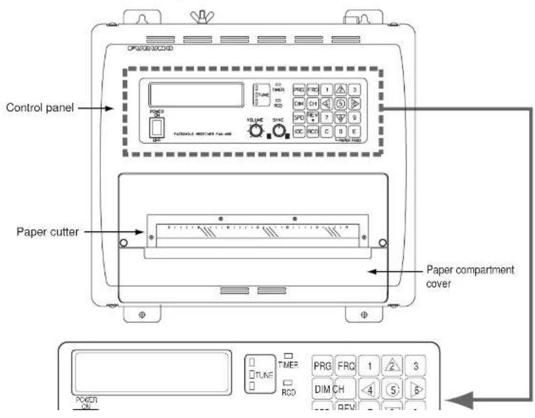
1. OPERATION
Control description (con't from previous page)
| Control, indicator | Description |
| PRG | Enables a setting mode (in combination with numeric key). Press the key followed by appropriate numeric key to choose setting mode.Chooses internal or external receiver.Sets timer reception functions.Sets sleep timer.Adds or edit channels.Sets date and time.Sets ISB shift.Adjusts LCD contrast.Clears RAM.Returns to top page in setting mode. |
| FRQ | Changes from channel mode to frequency mode.Sets frequency in frequency mode. |
| DIM | Adjust LCD brilliance and LED brightness, in five levels. |
| CH | Changes from frequency mode to channel mode.Sets channel in channel mode. |
| SPD | Chooses recording speed. |
| REV | Reverses recording format (from black on white to white on black and vice versa).Inserts decimal point when entering frequency, asterisk when entering channel.Chooses + or -. |
| IOC | Chooses IOC (Index of Cooperation). |
| RCD | Starts and stops recording in manual recording. |
| E | Confirms setting. |
| C | Clears data in setting mode. |
- OPERATION
1.2 Turning the Power On/Off
Press the POWER key to turn the power on or off. When the power is applied, the last-used channel appears.
1.3 Adjusting LCD Contrast
- Press the PRG key.
- Press the 7 key to show the contrast setting screen.
SET CONTRAST by ▲/▼ KEY
- Press ▲ or ▼ key to adjust the contrast, in 10 levels (0-9). The chosen level is indicated on the LCD.
- Press the E key.
- Press the C key to return to the standby display.
1.4 Adjusting LCD Brilliance and LED Brightness
Use the DIM key to adjust LCD brilliance and LED brightness, in five levels.
1.5 Channel and Frequency Displays
The channel display may be chosen with the CH key; the frequency display with the FRQ key.
The channel number is displayed in three digits. In the example below the channel number is 000.
CH No. Call Sign Frequency CH No. Call Sign Frequency
1. OPERATION
1.5.2 Selection of desired frequency, fine adjustment of frequency
Frequency may also be entered manually by pressing the FRQ key, and then entering frequency by using the numeric keys and the REW key (for entering decimal point). The available frequency range is 2000.0 - 24999.9 kHz.
In the frequency display mode, use the ▲ or ▼ key to fine tune a frequency when in the frequency display mode, in resolution of 0.1 kHz. When properly tuned, the center TUNE LED (green) lights. If the upper TUNE LED (red) is lit, use the ▲ key, and if the lower TUNE LED (red) is lit, use the ▼ key.
1.6 Automatic Receiving
Once you choose the facsimile station from which to receive, the system goes into standby to await the start signal from the facsimile station. Recording starts when the start signal is received.
- Press the CH key to show the channel display.
| C00* | JMH | 3622.5 |
| S120 | I576 |
^* Asterisk indicates automatic frequency selection.
- Press the ▲ or ▼ key to choose channel desired.
Note: Alternatively, you may enter the frequency of the broadcasting station by pressing the FRQ key and entering frequency with the numeric keys and the REV/- key (for decimal point).
When the start signal is received, the message "AUTO START SEARCHING FRAME" appears and the RCD LED (orange) flashes. Speed and IOC are automatically adjusted when recording starts. The RCD LED lights during recording.
Note: The TUNE LED goes off when the RX level goes below a certain level or the equipment is not receiving. Even if the TUNE LED goes off, the equipment records the fax signal as long as the S/N ratio is suitable. Therefore, this is not a sign of TUNE LED trouble or equipment malfunction.
1.7 Manual Receiving
This section shows you to manually receive a facsimile broadcast. For example, you may want to receive a facsimile broadcast already in progress or receive from a facsimile station that does not use start and stop signals.
- Press the CH key to show the channel display.
| C000 | JMH | 3622.5 |
| S120 | I576 |
- Press the ▲ or ▼ key to choose channel desired.
Note: Alternatively, you may enter the frequency of the broadcasting station by pressing the FRQ key and entering frequency with the numeric keys and the REV/·key (for decimal point).
- Press the RCD key to start receiving.
MANUAL START SEARCHING FRAME appears on the display and the RCD LED (orange) flashes. - If recording does not start after a while, press the RCD key again. The RCD LED stops flashing and lights when recording starts.
- If necessary, use the SPD key and IOC keys to choose rotation speed and IOC, respectively, referring to paragraph 1.9.1.
Stopping recording
Recording stops automatically when the stop signal is received. To stop recording manually, press the RCD key. The RCD LED goes off when recording is stopped.
1.8 Timer Receiving
Most facsimile stations transmit facsimile images in accordance with a schedule issued by relative meteorological observatory. (You can find facsimile schedules in the publication "Meteorological
- OPERATION
- Press the 4 key to choose STR (Store).
- Use the ▲ or ▼ key to choose timer program number and press the E key. For example, choose "1" and the display then looks something like the one below.
R1 SET CHANNEL No. in 3 FIGURES
- Enter a channel number and press the E key.
R1 C000 SET DAY of THE WEEK by ▲▼
- Set the day of the week which to receive the program, using the ▲ or ▼ key. Choose the asterisk (*) to get a broadcast daily at the same time.
- Press the E key.
R1 C000 MON SET START/STOP
- Set start and stop times, in 24-hour notation, using the numeric keys. (When registering programs which follow one another consecutively, the time between programs should be set at least one minute apart. For example, you have two programs to register, the first at 12:00-12:30 and the second at 12:30-13:00. In this case, set the time for the second program to 12:31-13:00.)
- Press the E key.
- Press the C key.
1.8.2 Choosing timer programs for timer reception
- OPERATION
1.8.3 Disabling timer operation when awaiting reception
Timer programs may be deleted from the timer reception schedule as follows.
- Press the PRG key, and the message shown below appears.
TIMER RCV : OFF?
PUSH E KEY
- Press the E key.
1.8.4 Unlocking the keyboard during timer reception
All keys except the PRG key are locked during recording to prevent accidental adjustment of the equipment. If you need to operate the keyboard when timer reception is active, do the following:
- Press the PRG key, and the following screen appears.
- Press the E key to unlock the keyboard.
1.8.5 Confirming timer programs
Do the following to confirm timer programs that you have entered.
- Press the PRG key and the 2 key to show the timer reception setting mode.
- Press the 3 key to choose RCL (Recall).
-
Use the ▲ or ▼ key to choose timer program number, and the contents of the timer program
-
OPERATION
1.9 Processing Facsimile Images
Speed, IOC, phasing, synchronization and image format may be adjusted during recording.
1.9.1 Speed and IOC
Choose the correct speed and IOC, otherwise the image will be received as shown in the illustration below.
Wrong Speed or IOC and Image
Wrong speed: "60" chosen instead of "120"
Two images are displayed.
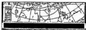
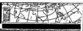
Wrong speed: "120" chosen instead of "60"
Overlapped image appears.

Wrong IOC
- OPERATION
loc
IOC is an acronym meaning Index of Cooperation, and it is the line density standard assigned by WMO: IOC 576, high density, IOC 288, low density. To choose IOC, do the following:
- Press the IOC key to show the IOC display.
IOC: 576
1-576 2-288
- Press the 1 or 2 key to choose appropriate IOC.
1.9.2 Manual phasing
When the FAX-408 starts recording a broadcast already in progress, or noise prevents detection of the phasing signal, a dead sector (black or white stripe) may appear on the recording. This phenomenon is due to phase mismatching. When this occurs, adjust recording position as shown below.

To adjust phasing, use the ◀ or ▶ key. Press ◀ to shift leftward; ▶ to shift rightward. Each press shifts the recording leftward (rightward) by about 5.0 mm.
1.9.3 Synchronization
If the dead sector is plotted at an angle even when the phase is properly selected, adjust the synchronization to display the dead sector straightly, using the SYNC control. Rotate the control counterclockwise if the picture is skewed leftward, or rotate it clockwise if the picture is skewed rightward.
- OPERATION
1.10 Sleep Timer
The sleep timer feature sleeps the set after reception has passed. Fax signal will not be received when the sleep timer is active.
1.10.1 Activating the sleep timer
- Press the PRG key.
- Press the 3 key to show the sleep mode setting mode.
SLEEP MODE : OFF 1-OFF 2-ON
- Press the 1 key to disable the sleep timer or the 2 key to enable it.
- If the 1 key was pressed at step 3, press the E key to turn off the sleep mode. If the 2 key was pressed, the display shown below appears. Go to step 5.
SLEEP TIME: SET SLEEP TIME
- Using the numeric keys, set the amount of time (within 23h59m) to sleep the set. To sleep the set 30 minutes later, for example, enter [0], [0], [3], [0].
- Press the E key.
The TIMER LED (orange) lights. IN SLEEP!! is displayed when the sleep function becomes active.
1.10.2 Unlocking the keyboard
All keys except the PRG key are locked when the sleep timer function is in standby (before specified time passes). To unlock the keyboard in this case, do the following:
- Press the PRG key to show the following menu.
KEYLOCK·OFF?
- OPERATION
1.11 Setting the Date and Time
- Press the PRG key.
- Press the 5 key to display the screen shown below.
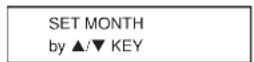
- Use the ▲ or ▼ key to set month, and press the E key.
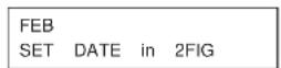
- Use the numeric keys to set date in two digits, and press the E key.

- Use the ▲ or ▼ key to set day of the week, and press the E key.
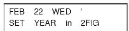
- Use the numeric keys to set year in two digits, and press the E key.
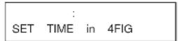
- Using 24-hour notation, enter time in four digits, and press the E key. The date and time appear momentarily.
- Press the C key to return to the standby display.
1.12 Adding Facsimile Channels
-
OPERATION
-
Enter call sign (3 characters), using the arrow keys, and press the E key. (Use the ◀ or ▶ key to choose location (with the cursor); use the ▲ or ▼ key to change character.) For example, enter JMH, and the display should look something like the one below.
C711 JMH 0.0 SET FREQUENCY
- Enter frequency, using the numeric keys and the REV4 key (for decimal point), and press the E key.
SET SPEED 120-60 1-120 2-90 3-60
- Press the 1, 2 or 3 key as appropriate to choose speed, and press the E key.
SET IOC 576/288 1-576 2-288
- Press the 1 or 2 key as appropriate to choose IOC, and press the E key.
SET REVERSE 1-OFF 2-ON
- Press the 1 key to print facsimile in the format it is received, or the 2 key for format reversal.
- Press the E key. The data for the channel is momentarily displayed and then the setting mode display appears.
- Press the C key to return to the standby display.
Existing channels may be edited similarly. Choose existing channel at step 2 and follow the remaining steps.
- OPERATION
1.13 ISB Function
The frequency of certain SSB multiplex broadcasts (fax and teletype) randomly shifts 1-2 kHz. To receive these broadcasts steadily, enable the ISB* function to track frequency.
* ISB is a single sideband mode which is used with some SSB transmissions. Normally each sideband carries identical information, but ISB modulates two different input signals - one on the upper sideband, the other on the lower sideband.
1.13.1 Enabling, disabling ISB function
- Press the PRG key followed by the 6 key.
ISB +0.0kHz : OFF
1-OFF 2-ON 3-QTY
- Press the 1 or 2 key to disable or enable the ISB shift function, respectively.
- Press the E key.
- Press the C key.
When the ISB function is enabled, the ISB shift width set in the procedure below is applied to the frequency shown on the frequency display. Further, the frequency shift is applied to ALL channels.
1.13.2 Set ISB shift width
Set the ISB shift width (from nominal frequency) to use as follows:
- Press the PRG key followed by the 6 key.
- Press the 3 key to choose QTY.
SET ISB in 2FIGS
+/- by • KEY
-
Prace the REV/. Key to display the + or - cian as appropriate
-
OPERATION
1.14 Operation with an External Receiver
When the receive signal is particularly weak or the internal receiver is producing only blurred recordings, you may wish to receive facsimile broadcasts with an external receiver.
1.14.1 Enabling, disabling external receiver use
- Press the PRG key followed by the 1 key.
AF IN:INT 1-INT 2-EXT
- Press the 1 key to use the internal receiver, or press the 2 key to use an external receiver.
- Press the E key.
1.14.2 Operation
Beat adjustment
When using an external receiver whose beat frequency is adjustable within a range of ±2 kHz or more by means of a beat knob, set the frequency dial so the deflection of the receiver's S-meter is maximum, and adjust the beat knob so that the center LED of the tuning indicator of this unit is lit. When a signal from a station with ISB communication (U.S. Naval Station Guam, Pearl Harbor, San Francisco, etc.) is received, sometimes an adjustment of the frequency is necessary, with a variable condenser, because the frequency may shift from the nominal frequency of the station by ±2 kHz.
Bandwidth
Increase bandwidth when noise is few, and lower bandwidth by about 1 kHz when noise is great.
Recording
2.MAINTENANCE

WARNING
Do not open the equipment except to replace paper.
Only qualified personnel should work inside the equipment.
2.1 Cleaning
Dust and dirt may be removed from the main unit with a soft cloth. For stubborn dirt, water diluted mild detergent may be used. DO NOT use chemical-based cleaners to clean the cabinet or control panel, as they can remove paint and markings.
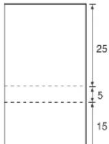
Random lines or dots appear on the recording when the thermal head is dirty. Clean the thermal head as shown in the procedure below, using the head cleaning sheet (#2000, supplied) and paper sensor jig, an ordinary white piece of paper cut and folded to the dimensions shown below.
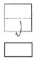
*Mountain fold
Mountain fold* Mountain fold*
2. MAINTENANCE
- Turn on the power.
- Press the 0 key until the sheet feeds out 5-15 cm.
- Set the paper release lever downward and remove the head cleaning sheet and paper sensor jig.
- Re-set the roll paper, paper compartment cover and paper cutter.
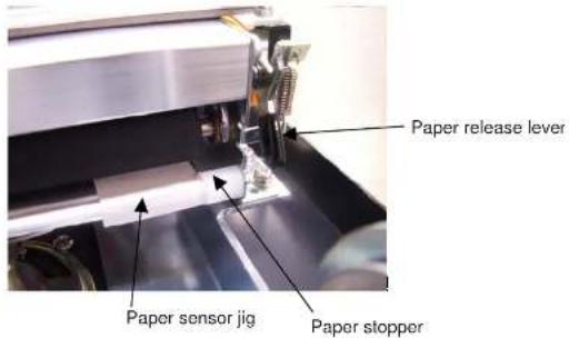
Note: Do not use the head cleaning sheet more than once per cleaning session and do not use a sheet whose grade is coarser than #2000. A coarser grade will damage the thermal head.
If the recording is still dirty
Turn off the power. Moisten a cotton swab with ethyl alcohol and insert between the thermal head and rubber roller, until about 4 mm of the swab is inserted. Move the swab to clean. USE ONLY ethyl alcohol to clean.
Use only a slight amount of ethyl alcohol. Excessive amount may dissolve corrosive components in printing chaff, which can damage the thermal head. Further, be sure the alcohol has dried completely before turning on the power.
- Open the paper cutter by loosening its two screws. Detach it together with the paper compartment cover. Put the paper feed lever in the downward position. See Figure 1.
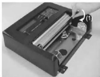
natural_image
Close-up of a hand inserting a component into a black electronic device (no visible text or symbols)Figure 1
- While pushing the paper guide (2) in the direction indicated, remove the remaining roll paper. See Figure 2.
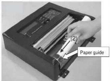
Figure 2
- Pass the recording paper between the paper-end detector lever and rubber roller.

-
MAINTENANCE
-
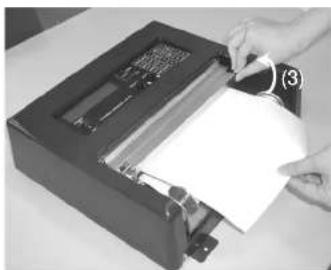
Pull the paper feed lever upward. Draw out the paper so that it will be a little past the front of the unit. See Figure 4.
natural_image
Person inserting a card into a device with paper inside (no visible text or symbols)Figure 4
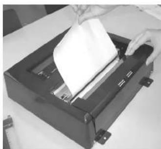
- Attach the paper compartment cover. See Figure 5.
natural_image
Person using a paper filter into a black printer (no visible text or symbols)Figure 5
2.3 Replacement of Fuse
A fuse at the rear of the main unit protects the equipment from overcurrent and equipment fault. If the power cannot be turned on, the fuse may have blown.

WARNING
Use the proper fuse.
Use of a wrong fuse can result in damage to the equipment or cause fire.
| Parts name Type | Code No. | |
| Fuse FGBO 125V 7A PBF 000-155-831-10 | ||
2.4 Backup Battery
The manganese lithium battery inside the main unit is used to keep the clock running, and its life is about five years. When the battery voltage is low the time is "slow." Have a qualified technician replace the battery when this occurs.
| Parts name Type Code No. | |
| Battery U130002 (CR-2032) 000-159-813 |
2.5 Clearing the RAM
The RAM stores frequency data of fax transmitting stations throughout the world. If part of the RAM was deleted in error, the data for fax transmitting stations can be retrieved from the ROM. In
2. MAINTENANCE
This page intentionally left blank.
3. INSTALLATION
3.1 Main Unit
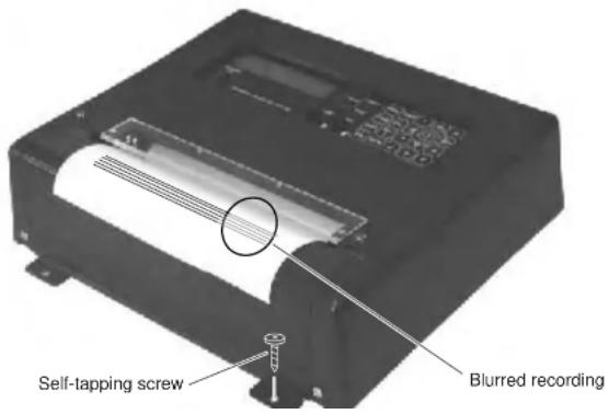
The main unit may be mounted on a tabletop or a bulkhead, using 5×25 self-tapping screws (supplied).
When choosing a mounting location, consider the following points:
- It is essential that the mounting surface is flat, otherwise blurred recordings may result, as in the example below. If it is necessary to level the unit, insert flat washer (supplied) between unit and mounting surface at appropriate location(s).
3. INSTALLATION
3.2 Antenna
The performance of the facsimile receiver is directly related to the antenna installation. In general, the antenna should be installed as high as possible on the vessel, free from the influence of nearby antennas, rigging and masts. Be sure to locate the antenna well away from TX antennas and noise generating equipment. Pay particular attention to the antennas of MF and HF radio equipment - they can damage the facsimile receiver through induction. (For better protection against induction, use the preamp unit.)
The FAX-408 can use the following antennas:
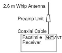
- Preamp unit FAX-5 (optional supply) + 2.6 m whip antenna (optional supply)
- Whip antenna (6 m, optional supply)
- Wire antenna (local supply)
3.2.1 General antenna connection
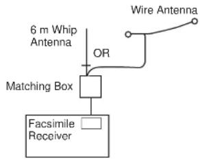
Connect the antenna to the facsimile receiver as shown below.
Preamp Used
flowchart
graph TD
    A["6 m Whip Antenna"] --> B["OR"]
    B --> C["Matching Box"]
    C --> D["Facsimile Receiver"]
    E["Wire Antenna"] --> F["OR"]
Preamp Not Used
- INSTALLATION
3.2.2 Whip or wire antenna
- Either a long wire or whip antenna may be used. A wire antenna should be 10 meters or longer including the vertical section. A whip antenna should be 6 meters long. Generally a whip antenna is suitable for reception over 6 MHz and wire antenna is suitable for reception under 6 MHz.
- The antenna can be shared with other receivers; use an antenna switch.
- If, when using a wire antenna, sensitivity is low, install the preamp unit (option).
3.2.3 Installation of optional preamp unit (FAX-5)
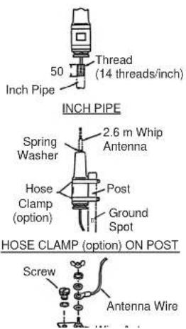
Small boats may not afford the space to install a long wire antenna. In this case it is recommended to install the preamp unit with 2.6 meter whip antenna. The preamp unit can be installed two ways:
- The base of the preamp unit is designed to accept a threaded extension of one-inch diameter. The pitch of the thread should be 14 threads per inch. The mast itself should be no longer than 1.5 meters to prevent flexing in heavy winds.
- Attach the preamp unit to a mounting post with stainless steel hose clamps (option).
Mounting
- Fix the preamp unit to the mounting location.
- Screw the whip antenna onto the preamp unit.
- If the mast is metallic, run a ground wire (local supply) between the mast and the ground terminal on the preamp unit.
- Waterproof the junction and other exposed metallic parts
- INSTALLATION
3.3 Wiring
See the diagram on page S-1 for detailed wiring information.
3.3.1 Power, ground
Battery
Connect black wire to "-" (negative) and red wire to "+" (positive).

Ground
Run the ground wire (supplied) between the GND terminal at the rear of the main unit and ship's superstructure. Do not share ground with other equipment.
3.3.2 External equipment
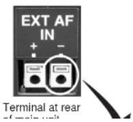
External equipment, such as a receiver, are connected to the terminal at the rear of the main unit.
How to connect wiring to terminal
3. INSTALLATION
External receiver connection
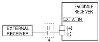
An external receiver may be used in place of the internal receiver. In this case, the receiver should have a local oscillator with very good frequency stability. Connect the external receiver to the EXT AF IN terminal at the rear of the set. This terminal operates against an input of greater than 50 mV. Excessive input is protected with a protective circuit. However, if direct current is used, input should be passed through a non-polarized capacitor of about 1 F.
flowchart
graph LR
    A["EXTERNAL RECEIVER"] --> B["+"]
    A --> C["-"]
    D["FACSIMILE RECEIVER"] --> E["EXT AF IN"]
    style A fill:#f9f,stroke:#333
    style D fill:#ccf,stroke:#333
1 F capacitor
3.3.3 Whip or wire antenna
If the preamp unit is not used, a matching box is required. Connect a feeder line between the antenna and matching box. Attach a connector to the coaxial cable and connect it between the receiver and the antenna. Use coaxial cable RG-10/UY or RG-12/UY.
How to attach M-connector
- Remove sheath by 30 mm.
- Make the length of the conductor 23 mm. Expose braided shield by 5 mm.
- Insert coupling ring onto cable.
- Insert plug assembly onto cable.
- Solder braided shield and plug assy. through hole in plug assy.
-
Tighten coupling ring to plug assy.
-
INSTALLATION
3.3.4 Setting of SW S1 on RCV board (when preamp unit is used)
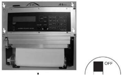
If the preamp unit is installed, turn on SW S1 on the RCV board in the facsimile receiver to power the preamp unit.
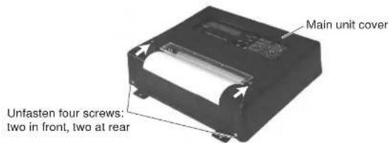
- Unfasten two screws marked with arrows in the figure below to detach the paper cutter and the paper compartment cover. Unfasten four screws to remove the main unit cover.
- Unfasten four screws marked with arrows and pull the LCD assy. forward. Use a plastic-bladed screwdriver to change position of S1 to ON. Reassemble the unit.
natural_image
Exterior view of a digital industrial machine with control panel and scroll (no visible text or symbols)- INSTALLATION
3.4 Changing Display Language
Display language is available in English, Dutch, Finnish, Norwegian, Swedish, Danish, Portuguese, Italian, German, Spanish and French, and the default language is English.
To change the display language, do the following:
- Turn on the power while pressing and holding down the PRG key.
TEST MODE (HR3) ESC POWER OFF
- Press the 8 key to show the following display.
LANG: English PUSH ▲/▼ &E KEY
- Use the ▲ or ▼ key to choose language desired.
- Press the E key.
- Turn off the power and turn it on again.
3. INSTALLATION
This page intentionally left blank.
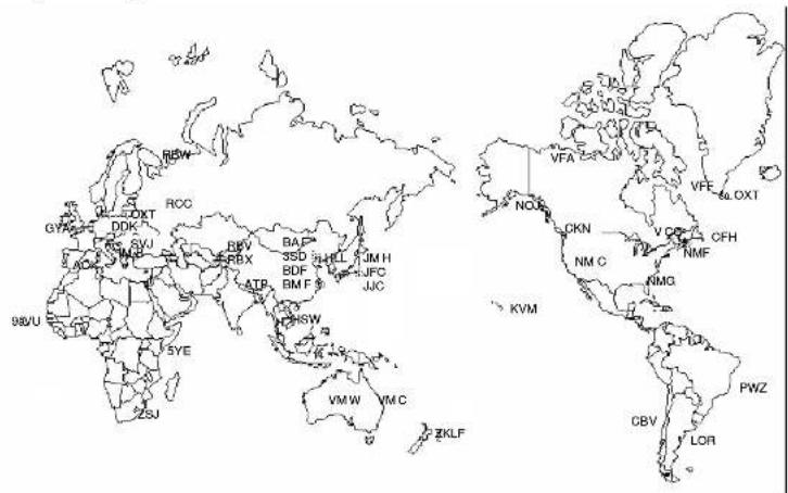
FACSIMILE STATION TABLES
This section shows the location and frequency data of all the existing frequencies of facsimile transmitting stations programmed into this unit's ROM. This data is for reference purposes. Data is subject to change without notice.
FACSIMILE STATION TABLE
| FREQUENCY FREQUENCY [kHz] [kHz] | CHANNEL NO. | CALL SIGN | STATION | ||
| 9 | |||||
| 3.9 | |||||
| SHANGHAI | 241.0 | ||||
| 7 | SHANGHAI | 5100.0 | |||
| 7 | SHANGHAI | 7420.0 | |||
| 7 | SHANGHAI | 11420.0 | |||
| 7 | SHANGHAI | 18940.0 | |||
| 070 BMF | TA | PAI 4616.0 | |||
| 4274.0 | 071 | BMF | TAIPAI | 5250.0 | |
| 6414.5 | 072 | BMF | TAIPAI | 8140.0 | |
| 8658.0 | 073 | BMF | TAIPAI | 13900.0 | |
| 13074.0 | 074 | BMF | TAIPAI | 18560.0 | |
| 080 | ZKLF | AUCKLAND | 3247.4 | ||
| 5385.0 | 081 | ZKLF | AUCKLAND | 5807.0 | |
| 5857.5 | 082 | ZKLF | AUCKLAND | 9459.0 | |
| 7433.5 | 083 | ZKLF | AUCKLAND | 13550.5 | |
| 9165.0 | 084 | ZKLF | AUCKLAND | 16340.1 | |
| 70.0 | |||||
| 090 VMC | CHARIEVILLE | 2628.0 | |||
| 5526.9 | 091 | VMC | CHARLEVILLE | 5100.0 | |
| 8121.9 | 092 | VMC | CHARLEVILLE | 11030.0 | |
| 10116.9 | 093 | VMC | CHARLEVILLE | 13920.0 | |
| 14366.9 | 094 | VMC | CHARLEVILLE | 20469.0 | |
| 16025.9 | |||||
| 18236.9 |
FACSIMILE STATION TABLES
| FREQUENCY FREQUENCY CHANNEL NO. | CALL SIGN | STATION | |||
| [kHz] [kHz] | |||||
| 5 | |||||
| 1.5 | |||||
| 0.0 | |||||
| RTO BELCRANO | 5705.0 | ||||
| 191 LOR | PUERTO BELGRANO | 12672.0 | |||
| 200 PWZ | RIO DE JANEIRO | 12663.0 | |||
| 9982.5 | 201 | PWZ | RIO DE JANEIRO | 16978.0 | |
| 11090.0 | |||||
| 16135.0 | 210 | CBV | VALPARAISO | 4228.0 | |
| 23331.5 | 211 | CBV | VALPARAISO | 8677.0 | |
| 212 | CBV VALPARAISO | 17149.4 | |||
| 6.8 | |||||
| 17520.0 | 220 | NMG | NEW ORLEANS | 4517.9 | |
| 221 | NMG | NEW ORLEANS | 8503.9 | ||
| 7404.9 | 222 | NMG | NEW ORLEANS | 12789.9 | |
| 14842.0 | 223 | NMG | NEW ORLEANS | 17146.4 | |
| 3289.5 | 230 | NMF | BOSTON | 4235.0 | |
| 6834.0 | 231 | NMF | BOSTON | 6540.5 | |
| 14436.0 | 232 | NMF | BOSTON | 9110.0 | |
| 18261.0 | 233 | NMF | BOSTON | 12750.0 | |
| 9044.9 | 240 | CFH | HALIFAX | 4271.0 | |
| 17447.5 | 241 | CFH | HALIFAX | 6496.4 | |
| 242 CFII | HALIFAX | 10536.0 | |||
| 4014.0 | 243 | CFH | HALIFAX | 13510.0 | |
| 7508.0 | |||||
| 13538.0 | |||||
| 18238.0 | |||||
FACSIMILE STATION TABLES
| FREQUENCY FREQUENCY[kHz] [kHz] | CHANNEL NO. | CALL SIGN | STATION | ||
| TASHKENT 3690.0 | |||||
| TASHKENT 4365.0 | |||||
| 342 RBV TASHKENT 5890.0 | |||||
| 343 FIBX TASHKENT 7570.0 | |||||
| 344 FICH TASHKENT 9540.0 | |||||
| 345 RBV TASHKENT | 14982.5 | ||||
| 8451.5 | |||||
| 350 RBX | TASHKENT2 | 3280.0 | |||
| . | 4616.0 | 351 | RBX | TASHKENT2 | 5285.0 |
| . | 6915.1 | 352 | BJ | TASHKENT2 | 8083.0 |
| . | 7708.1 | 353 | RCH | TASHKENT2 | 9150.0 |
| 354 | ROM | TASHKENT2 13947.0 | |||
| B. | 14770.0 | ||||
| 360 | RBW | MURMANSK | 5336.0 | ||
| 2054.0 | 361 | RBW | MURMANSK | 6445.5 | |
| 4298.0 | 362 | RBW | MURMANSK | 7908.8 | |
| 8459.0 | 363 | RBW | MURMANSK | 10130.0 | |
| 3412.5 | |||||
| 370 GYA | NORTHWOOD | 2618.5 | |||
| 4346.0 | 371 | GYA | NORTHWOOD | 4610.0 | |
| 8682.0 | 372 | GYA | NORTHWOOD | 8040.0 | |
| 12756.0 | 373 | GYA | NORTHWOOD | 11086.5 | |
| 17151.2 | |||||
| 22527.0 | 380 | DDH | HAMBURG | 3855.0 | |
| 381 DDK HAMBURG | 7580.0 | ||||
| 4777.5 | 382 | DDK | HAMBURG | 13882.5 | |
| 8146.5 | |||||
| 13597.4 | 390 | OXT | SKAMLEBARK | 5850.0 | |
| 391 OXT | SKAMLEBBAEK | 5860.0 | |||
| 4481.0 | 392 | OXT | SKAMLEBARK | 13855.0 | |
| 8105.0 | 393 | OXT | SKAMLEBARK | 17510.0 | |
FACSIMILE STATION TABLES
| FREQUENCY [kHz] | CHANNEL NO | CALL-SIGN STATION | FREQUENCY [kHz] | ||
SPECIFICATIONS OF FACSIMILE RECEIVER FAX-408
1 RECEIVER
1.1 Reception Synthesized double superheterodyne
1.2 Frequency range MF/HF 2.0000 - 24.99999 MHz
1.3 Mode F3C
1.4 Selectivity 2.0 kHz at -6 dB
1.5 Number of channels 314 channels (150 pre-set channels, 164 user channels)
1.6 Sensitivity MF/HF 2μV at 20 dB SINAD
1.7 Channel selection Automatic or manual, with numeric keys
1.8 Tuning indicator 3 LEDs
1.9 Display LCD, 32 characters in 2 lines
1.10 External signal input 1500 Hz (black) and 2300 Hz (white), FSK or FM signal
2 RECORDER
2.1 Recording system Electronic scanning w/thermal head
2.2 IOC Index of Cooperation, 576 and 288
2.3 Recording speed 60, 90, 120 scans per minute
2.4 Gradation 9 tones (white, 7 gray levels and black)
2.5 Recording paper Thermal paper (216 mm × 20 m)
2.6 Line density 8 dots/mm (total number of dots: 1696)
7.1 Frequency range 80 kHz - 30 MHz
7.2 Antenna Wire antenna or 2.6 m whip antenna
7.3 Input protection Withstand a 30 Vrms antenna input for 15 minutes
7.4 Output impedance 50 ohms
7.5 Power 9 VDC, fed from facsimile receiver via coaxial cable
-408-J/E
08AY-X-98517/1-1
| NAME OUT | INE O'TYDES | CRIPTION/CODE | B |
| 小型丸平座金FLAT WASHER | M6 SUS304 | 5 | |
| 000-864-029-03 | |||
| 図書 DOCUMENT | |||
| 取扱説明書OPERATOR'S MANUAL | OM* - 62620 - * | 1 | |
| 000-161-607-0 | |||
| 操作要領書(多言語)OPERATOR'S GUIDE | VLG-62620 - * | 1 | |
| 000-161-609-0 | |||
| ODH | 12 |
| 1 | |
| 38-0C | |
| P08-02 | |
| 77A | 2P |
| 31-0 | |
| P08-01 | |
| (#20010) | |
| 42-0 | |
| 1 | |
| 55-0 | |
| P08-02 | |
| 2 | 1 |
| 60-0C | |
| 9-10 | 1 |
| 120 | |
| 304 | 1491 |
| 53-0C | |
- IMPORTANT NOTICES
- SAFETY INSTRUCTIONS
- WARNING
- CAUTION
- Safety Instructions for the Operator
- WARNING LABEL
- Safety Instructions for the Installer
- TABLE OF CONTENTS
- INSTALLATION....21
- FACSIMILE STATION TABLES 29
- SPECIFICATIONS.... SP-1
- PACKING LIST......A-1
- OUTLINE DRAWINGS ....D-1
- INTERCONNECTION DIAGRAM....S-1
- FOREWORD
- A Word to the Owner of the FAX-408
- Features
- EQUIPMENT LIST
- OPERATION
- Turning the Power On/Off
- Adjusting LCD Contrast
- Adjusting LCD Brilliance and LED Brightness
- Channel and Frequency Displays
- Selection of desired frequency, fine adjustment of frequency
- Automatic Receiving
- Manual Receiving
- Stopping recording
- Timer Receiving
- Choosing timer programs for timer reception
- Disabling timer operation when awaiting reception
- Unlocking the keyboard during timer reception
- Confirming timer programs
- Processing Facsimile Images
- Speed and IOC
- Wrong Speed or IOC and Image
- loc
- Manual phasing
- Synchronization
- Sleep Timer
- Activating the sleep timer
- Unlocking the keyboard
- Setting the Date and Time
- Adding Facsimile Channels
- ISB Function
- Enabling, disabling ISB function
- Set ISB shift width
- Operation with an External Receiver
- Enabling, disabling external receiver use
- Operation
- Beat adjustment
- Bandwidth
- Recording
- 2.MAINTENANCE
- Cleaning
- MAINTENANCE
- If the recording is still dirty
- Replacement of Fuse
- Backup Battery
- Clearing the RAM
- INSTALLATION
- Main Unit
- Antenna
- General antenna connection
- Whip or wire antenna
- Installation of optional preamp unit (FAX-5)
- Mounting
- Wiring
- Power, ground
- Battery
- Ground
- External equipment
- External receiver connection
- Whip or wire antenna
- How to attach M-connector
- Setting of SW S1 on RCV board (when preamp unit is used)
- Changing Display Language
- FACSIMILE STATION TABLES
- SPECIFICATIONS OF FACSIMILE RECEIVER FAX-408
- RECEIVER
- RECORDER
Brand : FURUNO
Model : FAX-408
Category : Marine Electronics