AMP200 - Receiver OSD Audio - Free user manual and instructions
Find the device manual for free AMP200 OSD Audio in PDF.


| Product Type | Powered Amplifier (Receiver) |
| Brand | OSD Audio |
| Model | AMP200 |
| Power Output (Stereo) | 80W per channel into 8 ohms; 125W per channel into 4 ohms |
| Power Output (Bridged Mono) | 250W into 8 ohms |
| Frequency Response | 20Hz - 20kHz |
| Total Harmonic Distortion + Noise | <0.2% |
| Inputs | 2 x RCA line inputs (Line 1, Line 2); 1 x speaker level input |
| Outputs | 2 pairs of speaker terminals (Speaker A, Speaker B) |
| Speaker Impedance (Stereo) | Minimum 8 ohms per channel |
| Speaker Impedance (Bridged) | Minimum 8 ohms (total load) |
| Controls | Front: Power, Volume Trim, Balance Trim; Rear: Master Level controls (L/R), Mode switch (Stereo/Bridge), Delay Time adjustment |
| Indicators | Blue LED (active), Red LED (standby) |
| Power Supply | 115V/230V AC (selectable) |
| Warranty | Limited warranty; see manual for details |
| Safety Features | Includes safety instructions; do not expose to rain or moisture |
| Applications | Indoor/outdoor speaker distribution, whole-house audio, local zone amplification |
| Additional Features | Auto-source priority switching, delay timer for source return |
Frequently Asked Questions - AMP200 OSD Audio
User questions about AMP200 OSD Audio
0 question about this device. Answer the ones you know or ask your own.
Ask a new question about this device
Download the instructions for your Receiver in PDF format for free! Find your manual AMP200 - OSD Audio and take your electronic device back in hand. On this page are published all the documents necessary for the use of your device. AMP200 by OSD Audio.
USER MANUAL AMP200 OSD Audio
- TO PREVENT FIRE OR SHOCK HAZARD, DO NOT USE THIS PLUG WITH AN EXTENSION CORD, RECEPTACLE OR OTHER OUTLET UNLESS THE BLADES CAN BE FULLY INSERTED TO PREVENT BLADE EXPOSURE.
• TO PREVENT FIRE OR SHOCK HAZARD, DO NOT EXPOSE THIS APPLIANCE TO RAIN OR MOISTURE.
• TO PREVENT ELECTRICAL SHOCK, MATCH WIDE BLADE PLUG TO WIDE SLOT, FULLY INSERT.

This Lighting flash with arrowhead Symbol, within an equilateral triangle, is intended to alert the use to the Presence of un-insulated dangerous Voltage within the products enclosure That may be of sufficient magnitude To constitute a risk of electric shock To persons.
CAUTION
RISK OF ELECTRIC SHOCK DO NOT OPEN
Warning: To reduce the risk of Electric shock, do not remove Cover (or back) no user Servicing to qualified service Personnel.

The exclamation point within the Equilateral triangle is intended to Alert the user to the presence of Important operating and Maintenance (servicing) Instructions in the literature Accompanying suppliance.
IMPORTANT SAFETY INSTRUCTIONS
- Read these instructions.
- Keep these instructions.
3 Read all warnings.
MI5Powered Amplifier
natural_image
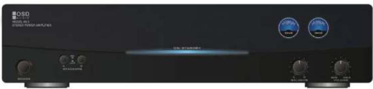
Front view of an OSD STANDER audio amplifier console (no visible text or symbols on the device body)Congratulations on your purchase of OSD Powered Amplifier.
Mi6 Powered Amplifier. Please take a few moments to read this entire manual, and be sure to retain this document for future reference please read and observe all safety instructions detailed on page.

Note: If any part of this product is damaged or missing, Please call OSD Audio Return Department At (714) 447-9850
Using the controls/ Front Panel
Power
The front panel switch will manually switch the MIS Powered Amplifier on or off. A blue led behind the faceplate lens indicates its power status. Whenever the amplifier's power switch is in the "ON" position and the amplifier is in "active" status the lens is illuminated blue. If the amplifier is "ON" but in the "standby" status the lens is illuminated RED.
Master Level Control
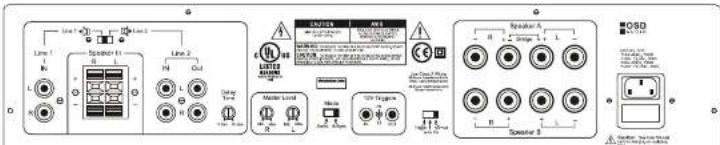
Each channel is able to control its volume independently relative to the other channel. At the bottom left of the rear panel, there are 2 screwdriver adjustment knots which correspond to the volume level of the channel identified by a channel designator below it.
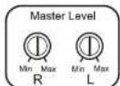
The volume range is labeled Minimum to Maximum and has 1 steps (clicks) at a center position as a reference. Rotate the knob clockwise to increase output, and counter clockwise to decrease output.
These adjustments set the master level and if not set up an initial setup of the MI5 Powered Amplifier will or may adversely affect the performance of the amplifier.
To set the Master Lever controls begin by adjusting the front panel "Volume Trim" to its fully clockwise position. Also set the front panel "Balance Trim" to its center position. Now adjust both the left and Right Channel Master Level controls to set a "Maximum" desired volume for the MI5 Powered Amplifier in its application, as well as setting an appropriate "Balance" from left to right.
Now the front panel Volume and Balance Trim controls can make fine adjustments to your set up in this application.
RCA input
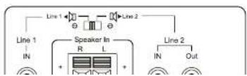
As an example, if the "line 1 Input" source was a CD Changer. The delay could be adjusted to prevent switching back to the "Line 2 Input" source while the changer moves from one disk to another.
Speaker Level Input
The MI6 Powered Amplifier also provides a pair of speaker level input for these applications where either of the sources has only speaker level output signal available. This input may be switched to be used in place of the line 1 or line 2 input.
Mode Switch
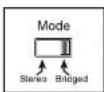
To the right to the master Level controls is a switch labeled "MODE" with "STEREO" and "BRIDGED" as options. If you will be connecting one or two pair of speaker to the amplifier, place the switch in the "STEREO" position.
If you will be suing a pair channel to power a single mono speaker, place the switch in the "BRIDGED" position, and be sure to read the section titled "Speaker Terminals" below.
When you are using the amplifier in "Bridged Mode", the amplifier is now a single channel mono amplifier. The two channels have been internally connected in series by the "Bridge" switch. The MI6 Powered Amplifier is now capable of 250W, bridged into 8 ohms with less than 0.2% THD+N.
For the amplifier to operate properly in the bridged mode you should have both the 'right and left' inputs connected to the amplifier. The amplifier will sum these signals and create your mono source.
Note: Both of the "Master Level" adjustments should be set to the same Position, and the "Balance Trim" should be set to the
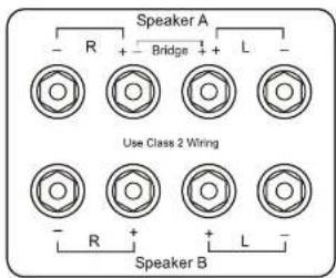
NOTE: Only one pair of channels can be bridged together. Do not attempt to bridge both A&B speaker terminals, as this may result in a lower impedance than the amplifier is designed to accommodate, and may damage your amplifier. The minimum impedance for the total load connected to a pair of channels in the bridged mode is 8-ohm.
NOTE: This amplifier is capable of use with standard US voltage (115 VAC) as well as European voltage (230 VAC). The amplifier will be preset for the voltage of the country it is sold in. Use with other voltages requires some changes to be made to the amplifier. Should you wish to use the amplifier in a country other than the one for which it was purchased, Please contact OSD AUDIO HOME PRODUCT AT (714) 447-9880
MI5 Powered Amplifier Specifications
Power Bandwidth 20Hz-20kHz
80W per CH into 8 ohm loads with less than 0.2% THD+N 125W per CH into 4 ohm loads with less than 0.2% THD+N 250W Bridged Mono into 6 ohms with less than 0.2% THD+N
This limited warranty applies only to purchases from authorized OSD Electronics retailers. This limited warranty is extended only to the original purchaser.
Consumers are required to provide a copy of the original sales invoice from an authorized OSD dealer when making a claim against the limited warranty. This limited warranty only covers failures due to defects in materials or workmanship that occur during normal use. It does not cover failures resulting from accident, misuse, abuse, neglect, mishandling, misapplication, alteration, faulty installation, modification, service by anyone other than OSD or damage that is attributable to acts of god. It does not cover costs of transportation to OSD or damage in transit. The customer should return their defective product, freight prepaid and insured, to OSD AUDIO. Only after receiving a Return Authorization.
This warranty will become void if the serial number identification has been wholly or partially removed, altered or erased. Repair or replacement under the terms of this warranty does not extend the terms of this warranty. Should a product prove to be defective in workmanship or material, the consumer's sole remedies will be repair or replacements as provided under the terms of this warranty. Under no circumstances shall OSD be liable for loss or damage, direct, consequential or incidental, arising out of the use of or inability to use the product. There are no express warranties other than described above
Applications
Powering Speaker Outdoors
Whenever you are using loudspeakers outdoors, you should be aware that sound does not travel like it would in your home. Without the reflective surfaces of walls and ceilings, sound outdoors will dissipate quickly. Therefore, in an outdoor situation the MI6 Powered Amplifier provides the opportunity in kidney secreted
Stereo Setup
In this configuration, the mono switch is set to stereo for stereo operation. Connect the line out jacks from a stereo preamplifier or source to the Line 2 input jacks of your M5 Powered Amplifier. Next connect your speakers to the terminals marked "SPEAKER A" observing proper polarity (see "speaker terminals" Page 5). Connect a second (optional) pair of speakers to the terminals marked "SPEAKER B". Select between the "A" and or "B" speakers using front panel speaker selection buttons.
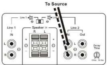
Mono Setup
In this configuration, the mono switch is set to bridge. Connect the line out from a preamplifier to the right and left Line 2 input of your MI5 Powered Amplifier. Connect your mono speaker to the terminals of your MI5 Powered Amplifier, following the instructions in "Speaker Terminals" on Page 4. Use the "Master Level" controls on the rear panel to adjust the volume. Leave the balance set to the center defect position.
Setup For Multiple Sources
In the application shown below, a distributed audio system is connected to the MI5 Powered Amplifier as a local zone amplifier via the Line 2 inputs. Normally the distributed audio system will be the audio source for the MI5 Powered Amplifier.
The distributed audio is then neural and to be read by additional
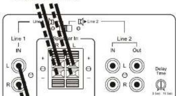
The distributed audio is then passed on to be used by additional zones or sub zones in the distributed system via the Line 2 outputs. The Audio output of a local source, such as MP3 Player, CD, television, computer, etc., is connected to the MI5 Powered Amplifier via the television, computer etc.. Is connected to the MI5 Powered Amplifier via the Line 1 inputs, and whenever the local source is active its signal will take priority over the distributed audio signal present at Line 2. However, the distributed audio signal will still be present at the Line 2 input. In this circumstance the audio output of the local source will be heard via the MI5 Powered Amplifier. Once the local source is turned off or muted, the MI5 Powered Amplifier will automatically switch back the distributed audio system as an audio source, assuming the television is remains inactive. The delay time adjustment determines when switch back to the normal source will occur.
This set up assumes all incoming signals are at line level and not at speaker level. If the Whole House Distributed Audio was only available as a speaker Level signal you could connect it the "speaker In" connections and set the switch above to the "Line 2" position, or toward the right hand position of the switch.
Whole House
Distributed Audio
Brand : OSD Audio
Model : AMP200
Category : Receiver