
KE6940T - Extendeur AV ATEN - Free user manual and instructions
Find the device manual for free KE6940T ATEN in PDF.


| Product Type | DVI KVM Over IP Extender (Transmitter only, optional receiver sold separately) |
| Model Number | KE6940T (Transmitter), KE6940R (Receiver) |
| Video Connectors | 2 x DVI-I Female (White) on console; 2 x DVI-I Female (White) on KVM ports |
| Console Ports | Keyboard: 1 x USB Type A Female (White); Mouse: 1 x USB Type A Female (White); Speaker: 1 x Mini Stereo Jack Female (Green); Mic: 1 x Mini Stereo Jack Female (Pink); RS-232: 1 x DB-9 Male (Black); Power: 1 x DC Jack (Black); LAN: 1 x RJ-45 Female (Black) |
| KVM Ports | KB/Mouse: USB Type B Female (White); Speaker: 1 x Mini Stereo Jack (Green); Mic: 1 x Mini Stereo Jack (Pink); Video: 2 x DVI-I Female (White); RS-232: 1 x DB-9 Female (Black) |
| Maximum Video Resolution | 1920 x 1200 @ 60 Hz; 24-bit color depth |
| Power Consumption | DC 5V (power adapter included) |
| Dimensions (W x D x H) | 22.80 x 17.10 x 55.00 cm (9.0 x 6.7 x 21.7 in) |
| Weight | 1.25 kg (2.76 lbs) |
| Housing Material | Metal |
| Operating Temperature | 0°C to 50°C (32°F to 122°F) |
| Storage Temperature | -20°C to 60°C (-4°F to 140°F) |
| Humidity | 0% to 95% RH, non-condensing |
| Main Features | Dual DVI support, remote KVM access over LAN, RS-232 serial ports, OSD configuration, Matrix Manager software support, Auto-MDIX, virtual media support, rack mountable, firmware upgradeable |
| Package Contents | 1 x KE6940T Transmitter, 1 x KE6940R Receiver, 2 x Power Adapters, 1 x USB KVM Cable, 1 x DVI-D Cable (2m), 1 x Mounting Kit, 1 x User Instructions |
| EMC Standards | FCC Class A, CE Class A, RoHS compliant |
| Safety Instructions | Indoor use only; do not expose to water; ensure proper ventilation; use surge suppressor; refer servicing to qualified personnel |
| Warranty | 1 year limited warranty (defects in material or workmanship) |
Frequently Asked Questions - KE6940T ATEN
User questions about KE6940T ATEN
0 question about this device. Answer the ones you know or ask your own.
Ask a new question about this device
Download the instructions for your Extendeur AV in PDF format for free! Find your manual KE6940T - ATEN and take your electronic device back in hand. On this page are published all the documents necessary for the use of your device. KE6940T by ATEN.
USER MANUAL KE6940T ATEN
DVI KVM Over IP Extender
KE6900 / KE6940
User Manual
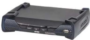
natural_image
Exterior view of a black electronic device labeled 'AT&T' with ports and ventilation slots (no readable text beyond branding)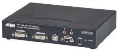
natural_image
Black electronic device with ports and connectors (no visible text or symbols)FCC, CE Information
FEDERAL COMMUNICATIONS COMMISSION INTERFERENCE STATEMENT: This equipment has been tested and found to comply with the limits for a Class A digital device, pursuant to Part 15 of the FCC Rules. These limits are designed to provide reasonable protection against harmful interference when the equipment is operated in a commercial environment. This equipment generates, uses, and can radiate radio frequency energy and, if not installed and used in accordance with the instruction manual, may cause harmful interference to radio communications. Operation Matrix Manager of this equipment in a residential area is likely to cause harmful interference in which case the user will be required to correct the interference at his own expense.
FCC Caution: Any changes or modifications not expressly approved by the party responsible for compliance could void the user's authority to operate this equipment.
CE Warning: This is a class A product. In a domestic environment this product may cause radio interference in which case the user may be required to take adequate measures.
RoHS
This product is RoHS compliant.
SJ/T 11364-2006
The following contains information that relates to China.
Be sure to register your product at our online support center:
International http://eservice.aten.com
Telephone Support
For telephone support, call this number:
| International 886-2-86 | 92-5959 |
| China 86-10-5255-01 | 0 |
| Japan 81-3-5615-581 | |
| Korea 82-2-467-6789 | |
| North America 1-888 | 999 ATEN ext 4988 |
| United Kingdom 44-8 | 4481-58923 |
User Notice
All information, documentation, and specifications contained in this manual are subject to change without prior notification by the manufacturer. The manufacturer makes no representations or warranties, either expressed or implied, with respect to the contents hereof and specifically disclaims any warranties as to merchantability or fitness for any particular purpose. Any of the manufacturer's software described in this manual is sold or licensed as is. Should the programs prove defective following their purchase, the buyer (and not the manufacturer, its distributor, or its dealer), assumes the entire cost of all necessary servicing, repair and any incidental or consequential damages resulting from any defect in the software.
The manufacturer of this system is not responsible for any radio and/or TV interference caused by unauthorized modifications to this device. It is the responsibility of the user to correct such interference.
The manufacturer is not responsible for any damage incurred in the operation of this system if the correct operational voltage setting was not selected prior
KE6900 / KE6940 User Manual
Package Contents
Basic Package
The basic KE6900 / KE6940 package consists of:
1 KE6900T / KE6940T DVI KVM Over IP Extender
1 KE6900R / KE6940R DVI KVM Over IP Extender
2 Power Adapters
1 USB KVM Cable
1 DVI-D Cable 2m (KE6940 only)
1 Mounting Kits
1 User Instructions*
Check to make sure that all of the components are present and in good order. If anything is missing, or was damaged in shipping, contact your dealer.
Read this manual thoroughly and follow the installation and operation procedures carefully to prevent any damage to the switch or to any other devices on the KE6900 / KE6940 installation.
* Features may have been added to the KE6900 / KE6940 since this manual was published. Please visit our website to download the most up-to-date version.
KE6900 / KE6940 User Manual
Contents
FCC, CE Information....ii
SJ/T 11364-2006....ii
User Information ....iii
Online Registration ....III
Telephone Support....iii
User Notice ....iii
Package Contents.... iv
Basic Package.... iv
About This Manual IX
Conventions XI Product Information
Chapter 1.
Introduction
Overview....1
Features 2
Requirements 3
Console 3
Computers....3
Cables 3
Software 3
Operating Systems 4
Components 5
KE6900T (Transmitter) Front View 5
KE6900T (Transmitter) Rear View 6
KE6900R (Receiver) Front View 7
KE6900R (Receiver) Rear View....8
KE6940T (Transmitter) Front View 9
KE6940T (Transmitter) Rear View 10
KE6940R (Receiver) Front View 11
KE6940R (Receiver) Rear View 12
Chapter 2.
Hardware Setup
Rack Mounting 13
Wall Mounting....15
Setting Up a Point-to-Point Installation 16
Point-to-Point Installation 1 of 2 17
Point-to-Point Installation 2 of 2....18
Setting In a LAN Installation 10
KE6900 / KE6940 User Manual
Default IP Addresses 24
Chapter 3.
OSD Operation
Overview 25 LED Display 25
LED Display 25 Involving the OSD 26
OSD Interface. 27
User Station Configuration 28
Network. 28
Properties 29 System 21
Transmitter Configuration 32
Network. 32
Properties 33 Custom 86
User Preferences 37
Connecting 38
Connections Page. 39
Profile Page. 41
Chapter 4.
Matrix Manager Installation
Overview....43
Download 43 Matrix Manager install 15
Matrix Manager Install 45
Chapter 5.
Browser Operation
Overview. 49
Logging In. 49 The Matrix Manager Main Page 50
The Matrix Manager Main Page 50 Web Components 50
Tree View Considerations....51
The Tab Bar 52
Chapter 6.
Dashboard
Overview....53
Active Connections 54
Active Sessions....54 Online User Stations....55
KE6900 / KE6940 User Manual
Chapter 7.
Device Management
Overview....57 User Stations....58
Adding a User Station....59
Configuring a User Station....60
Deleting a User Station....63
Rx Video Group....64
Hardware Setup 64
Adding an Rx Video Group .65
Transmitters 67
Adding a Transmitter....68
Configuring a Transmitter 69
Deleting a Transmitter....73
Target Connections....74
Targets....75
Adding a Target....76
Target Groups....79
Adding a Target Group....79
Profiles 81
Adding a Profile....82
Chapter 8.
User Management
Overview....85
Users....86
Adding Users....86
Modifying User Accounts....88
Deleting User Accounts....88
Groups 89
Creating Groups....89
Modifying Groups 90
Deleting Groups 90
Users and Groups....91
Assigning Users to a Group From the User's Notebook....91
Removing Users From a Group From the User's Notebook . . . . . . .92
Assigning Users to a Group From the Group's Notebook....93
Removing Users From a Group From the Group's Notebook .....94
Device 95
Assigning Device Permissions From the User's Notebook .....95
Assigning Device Permissions From the Groups' Notebook. . . . . . .97
KE6900 / KE6940 User Manual
ANMS 102
Event Destination 102
Authentication & Authorization 104
Redundancy 107
Chapter 10.
Logs
Overview....111
System Log. 112
Filter 113
Chapter 11.
Maintenance
Overview....115
Firmware Upgrade 118
Firmware Upgrade Recovery 119
Certificates 120
Private Certificate 120
Certificate Signing Request....121
Preferences 123
Chapter 12.
Firmware Upgrade Utility
Preparation 125
Starting the Upgrade....126
Upgrade Succeeded. 128
Firmware Upgrade Recovery 129
Appendix
Safety Instructions 131
General 131
Rack Mounting 133
Technical Support. 134
International 134
North America....134
Specifications 135
IP Installer....137
Trusted Certificates. 138
Overview....138
About This Manual
This User Manual is provided to help you get the most from your KE6900 / KE6940 system. It covers all aspects of installation, configuration and operation. An overview of the information found in the manual is provided below.
Chapter 1, Introduction, introduces you to the KE6900 / KE6940 System. Its purpose, features and benefits are presented, and its front and back panel components are described.
Chapter 2, Hardware Setup, provides step-by-step instructions for setting up your installation, and explains some basic operation procedures.
Chapter 3, OSD Operation, explains the fundamental concepts involved in operating the KE6900 / KE6940 system, and provides a complete description of the On Screen Displays (OSDs) and how to work with them.
Chapter 4, Matrix Manager Installation, explains the administrative procedures that are required to download and install the Matrix Manager software.
Chapter 5, Browser Operation, explains how to log in to the Matrix Manager with a web browser, and describes the features, functions, and how to work with the browser's interface.
Chapter 6, Dashboard, explains how to use the Matrix Manager's Dashboard tab to view connection, session, and device events.
Chapter 7, Device Management, explains how to add, configure, and organize the Transmitter and Receiver devices that will be managed over the network, as well as how to create Targets and Profiles for matrix connections.
Chapter 8, User Management, describes how to add, modify and delete user accounts; create user groups and assign users to them; specify access rights for users and groups; and specify user authentication.
Chapter 9, System, explains the Matrix Manager's global settings, and ANMS settings for LDAP/AD, RADIUS, and TACACS+ authentication and authorization.
Chapter 10, Logs, explains how to access, filter, and search the various logs that are kept by the Matrix Manager.
KE6900 / KE6940 User Manual
Chapter 12, Firmware Upgrade Utility, explains how to download and use the Firmware Upgrade Utility to install new firmware on the devices.
An Appendix, at the end of the manual provides technical and troubleshooting information.
KE6900 / KE6940 User Manual
Conventions
This manual uses the following conventions:
Monospaced Indicates text that you should key in.
[] Indicates keys you should press. For example, [Enter] means to press the Enter key. If keys need to be chorded, they appear together in the same bracket with a plus sign between them: [Ctrl+Alt].
- Numbered lists represent procedures with sequential steps.
- Bullet lists provide information, but do not involve sequential steps.
→ Indicates selecting the option (on a menu or dialog box, for example), that comes next. For example, Start → Run means to open the Start menu, and then select Run.

Product Information
For information about all ALTUSEN products and how they can help you connect without limits, visit ALTUSEN on the Web or contact an ALTUSEN Authorized Reseller. Visit ALTUSEN on the Web for a list of locations and telephone numbers:
International http://www.aten.com
North America http://www.aten-usa.com
This Page Intentionally Left Blank
Chapter 1 Introduction
Overview
The KE6900 / KE6940 DVI KVM Over IP Extender is an IP based matrix extender that allows access to a computer system from a remote USB KVM console anywhere over a LAN. The KE6900 series is a single view extender that supports one DVI display at each end. The KE6940 series is a dual view extender that supports two DVI displays at each end, allowing the video output to display across two monitors.
The KE6900 / KE6940 consists of a transmitter that connects to the computer and a receiver that provides console access from a separate location. The computer is accessed from the remote console via a standard TCP/IP network or direct Ethernet cable connection. This is perfect for any installation where you need to place the console where it is convenient, but you want the computer to reside in a secure location - away from the keyboard, mouse and display.
As a matrix extender it can connect one or more: computers-to-consoles in several ways: one-to-one (Extender mode), one-to-many (Splitter mode), many-to-onc (Switch mode), or many-to-many (Matrix mode).
The KE6900 / KE6940 has a local On Screen Display (OSD) on the receiver to configure both units - for easy setup and operation. Using the transmitter and receiver over a standard TCP/IP network (optional) via Cat 5e cable allows point-to-point, point-to-multipoint, and multipoint-to-multipoint administration without needing a KVM switch. Both the transmitter and receiver have RS-232 ports to connect to a serial terminal for configuration or serial devices such as touchscreens and barcode scanners.
The Matrix Manager® software provides advanced features for username and password authentication, auto-detection of devices on the same LAN segment, management of devices, and setup of Splitter, Switch, and Matrix modes. New security features also provide extra protection with remote login security, a username and password can be required when the receiver connects to the transmitter.
Features
- Remote KVM console access of computers over LAN or Ethernet cable connection
- Dual console operation – control your system from both the Transmitter and Receiver by USB keyboard, monitor, and mouse
RS-232 serial ports ^1 – allows you to connect to a serial terminal for configuration, and serial devices such as touchscreens and barcode scanners - Superior video quality – up to 1920 x 1200 @ 60 Hz; 24-bit color depth
• Supports standard VGA resolutions from 640 x 480 to 1920 x 1200 at 60Hz - OSD (On Screen Display) on the Receiver configures both units
• Supports AP GUI operation
• Supports Web GUF administration - Remote login security
• DVI digital and analog monitor support
Built-in ESD protection and surge protection
• Supports stereo speakers and microphone - Auto-MDIX - automatically detects cable type
• Supports widescreen formats
• Supports High-Quality Video streaming
• Virtual Media Support - Hot pluggable
- Rack Mountable
- Upgradeable firmware
Note: 1. RS-232 serial ports support Tx/Rx/CTS/RTS/DTR/DSR signals only.
- The Matrix Manager web GUI can be downloaded from the ATEN website (www.aten.com).
Requirements
Console
♦ (KE6900) One DVI compatible monitors capable of the highest possible resolution
♦ (KE6940) Two DVI compatible monitors capable of the highest possible resolution
• A USB mouse
A USB keyboard
♦ Microphone and speakers
Computers
The following equipment must be installed on each computer that is to be connected to the system:
♦ (KE6900) Onc DVI port
♦ (KE6940) Two DVI ports
• USB Type A port
♦ Audio ports
Cables
For optimal signal integrity and to simplify the setup, we strongly recommend that you only use the high quality custom USB KVM Cable that is provided with this package.
Software
The minimum hardware and software requirements for the computer running the Matrix Manager software are:
◆ Processor: Intel or AMD processor 1 GHz or above
• RAM: 2GB or above
♦ HDD: 16GB or above
- Web browser
▲ Large Donations Environment (IDF) & with update 11 on choice
KE6900 / KE694D User Manual
Operating Systems
Supported operating systems are shown in the table, below:
OS Version
Windows 2000 and higher
Linux RedHat 6.0 and higher
SuSE 8.2 and higher
Mandriva (Mandrake) 9.0 and higher
UNIX AIX 4.3 and higher
FreeBSD 3.51 and higher
Sun Solaris 8 and higher
Novell Netware 5.0 and higher
Mac OS 9 and higher
Chapter 1. Introduction
Components
KE6900T (Transmitter) Front View
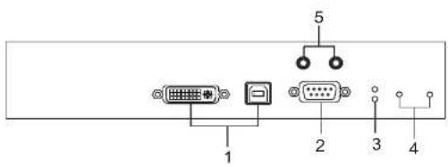
No. Component Description
| 1 KVM Ports The USB KVM cable supplied with the package that links the Transmitter to the computer plugs into these ports. |
| 2 RS-232 Port This RS-232 serial port is for connecting to the computer for serial control. |
| 3 Remote / Local LED Lights Green to indicate which side of the installation (Local or Remote) currently has KVM control of the computer. |
| 4 LAN / Power LED The unit has two LEDs to indicate Status and Power. |
| 5 Audio Ports These mini stereo ports are for the speakers (green) and microphone (pink). |
KE6900T (Transmitter) Rear View
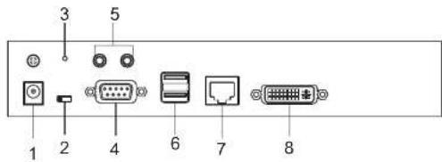
| No. Component Description | |
| 1 Power Jack The cable from the DC Power adapter connects here. | |
| 2 Function Switch Use this slide switch to set the unit's mode to:Configure: The device is ready to configure.Local: Only the local Transmitter has KVM control of the computer. The Receivers KVM access to the computer is locked.Auto: Shared KVM control of the computer, one at a time, with the Transmitter and Receiver consoles. | |
| 3 Reset This switch must be pushed with a thin object, such as the end of a paper clip.Press and release to reboot the device.Power off, hold reset then power on the device while pressing reset to recover from a firmware upgrade failure.Press and hold it in for more then three seconds resets the unit back to its factory default settings. | |
| 4 RS-232 Port This RS-232 serial port is for connecting to a serial terminal. | |
| 5 Audio Ports These mini stereo ports are for the speakers (green) and microphone (pink). | |
| 6 Console Ports The unit's USB keyboard and USB mouse plug into these ports. | |
| 7 LAN Port The cable that connects the unit to the LAN plugs in home. | |
Chapter 1. Introduction
KE6900R (Receiver) Front View
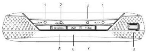
| No. | Component Description |
| 1 | Power LED Lights blue to indicate the module is turned on. |
| 2 | LAN LED Lights to indicate the network status:Lights Green when connected to the LAN.Olf when not connected to the LAN.Blinks Green when the Ethernet connection is active.Lights Orange to indicate high network bandwidth (for ultra-high video) is being used. |
| 3 | Local LED Lights green to indicate the Transmitter has KVM access of the computer. |
| 4 | Remote LED Lights green to Indicate the Receiver has KVM access of the computer. |
| 5 | Graphics Pushbutton Sets the displays image quality to the highest possible grade, so that images are optimized. |
| 6 | OSD Pushbutton Use this pushbutton to open the OSD menu. |
| 7 | Video Pushbutton Sets the displays image quality to a grade that is optimized for video playback. |
| 8 | USB Port Use this port for virtual media or a USB peripheral device.Note:When using a USB disk plugged into this port, see USB Mode, page 62. |
KE6900R (Receiver) Rear View
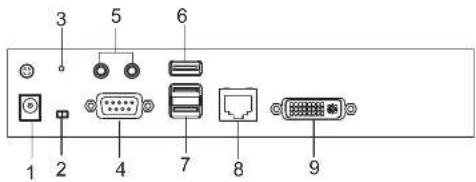
| No. | Component Description | |
| 1 | Power Jack The cable from the DC Power adapter connects here. | |
| 2 | Function Switch Use this side switch to set the unit's mode:Configure: The device is ready to configure.Auto: KVM control of the remote computer. | |
| 3 | Reset This switch must be pushed with a thin object, such as the end of a paper clip.Press and release to reboot the device.Power off, hold reset then power on the device while pressing reset to recover from a firmware upgrade failure.Press and hold it in for more then three seconds resets the unit back to its factory default settings. | |
| 4 | RS 232 Port This RS 232 serial port is for connecting to a serial terminal. | |
| 5 | Audio Ports These mini ste stereo ports are for the local speakers (green) and microphone (pink). | |
| 6 | USB Port Use this port for virtual media or a USB peripheral device.Note: When using a USB disk plugged into this port, see USB Mode, page 62. | |
| 7 | Console Ports The unit's USB keyboard and USB mouse plug into these ports. When using a keyboard or mouse with special functions, see USB Mode, page 62 | |
Chapter 1. Introduction
KE6940T (Transmitter) Front View
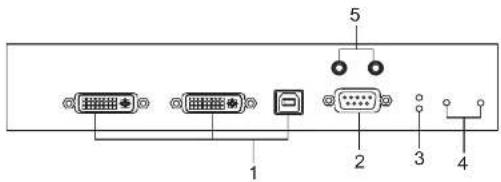
| No. | Component Description | |
| 1 | KVM Ports The USB KVM | cable supplied with the package that links the Transmitter to the computer plugs into these ports. |
| 2 | RS-232 Port This RS-232 | serial port is for connecting to the computer for serial control. |
| 3 | Remote / Local LED Lights | Green to indicate which side of the installation (Local or Remote) has KVM control of the computer. |
| 4 | LAN / Power LED The unit | has two LEDs to indicate Status and Power. |
| 5 | Audio Ports These mini stereo ports are for the speakers (green) and microphone (pink). | |
KE6940T (Transmitter) Rear View
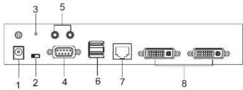
No. Component Description
| 1 Power Jack The cable from the DC Power adapter connects here. |
| 2 Function Switch Use this slide switch to set the unit's mode to:Configure: The device is ready to configure.Local: Only the local Transmitter has KVM control of the computer. The Receivers KVM access to the computer is locked.Auto: Shared KVM control of the computer, one at a time, with the Transmitter and Receiver consoles. |
| 3 Reset This switch must be pushed with a thin object, such as the end of a paper clip.Press and release to reboot the device.Power off, hold reset then power on the device while pressing reset to recover from a firmware upgrade failure.Press and hold it in for more then three seconds resets the unit back to its factory default settings. |
| 4 RS-232 Port This RS-232 serial port is for connecting to a serial terminal. |
| 5 Audio Ports These mini stereo ports are for the local speakers (green) and microphone (pink). |
| 6 Console Ports The unit's USB keyboard and USB mouse plug into these ports. |
| 7 LAN Port The cable that connects the unit to the LAN plugs in horn. |
Chapter 1. Introduction
KE6940R (Receiver) Front View
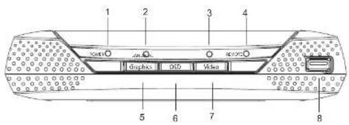
| No. | Component Description |
| 1 | Power LED Lights blue to indicate the module is turned on. |
| 2 | LAN LED Lights to indicate the network status:Lights Green when connected to the LAN.Olf when not connected to the LAN.Blinks Green when the Ethernet connection is active.Lights Orange to indicate high network bandwidth (for ultra-high video) is being used. |
| 3 | Local LED Lights green to indicate the Transmitter has KVM access of the computer. |
| 4 | Remote LED Lights green to Indicate the Receiver has KVM access of the computer. |
| 5 | Graphics Pushbutton Sets the displays image quality to the highest possible grade, so that images are optimized. |
| 6 | OSD Pushbutton Use this pushbutton to open the OSD menu. |
| 7 | Video Pushbutton Sets the displays image quality to a grade that is optimized for video playback. |
| 8 | USB port Use this port for virtual media or a USB peripheral device.Note:When using a USB disk plugged into this port, see USB Mode, page 62. |
KE6940R (Receiver) Rear View
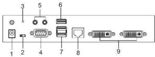
| No. | Component Description | |
| 1 | Power Jack The cable from the DC Power adapter connects here. | |
| 2 | Function Switch Use this side switch to set the unit's mode:Configure: The device is ready to configure.Auto: KVM control of the computer. | |
| 3 | Reset This switch must be pushed with a thin object, such as the end of a paper clip.Press and release to reboot the device.Power off, hold reset then power on the device while pressing reset to recover from a firmware upgrade failure.Press and hold it in for more then three seconds resets the unit back to its factory default settings. | |
| 4 | RS 232 Port This RS 232 serial port is for connecting to a serial terminal. | |
| 5 | Audio Ports These mini ste stereo ports are for the local speakers (green) and microphone (pink). | |
| 6 | USB Port Use this port for virtual media or a USB peripheral device.Note: When using a USB disk plugged into this port, see USB Mode, page 62. | |
| 7 | Console Ports The unit's USB keyboard and USB mouse plug into these ports. | |
| 8 | LAN Port The cable that connects the unit to the LAN plugs in | |
Chapter 2 Hardware Setup

-
Important safety information regarding the placement of this device is found on page 131. Please review it before proceeding.
-
Make sure that the power to all devices connected to the installation is turned off. You must unplug the power cords of any computers that have the Keyboard Power On function.
Rack Mounting
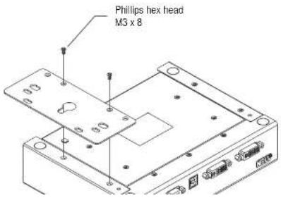
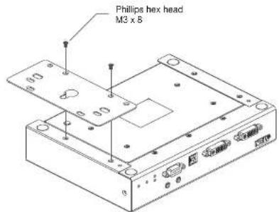
For convenience and flexibility, the Transmitter can be mounted on system racks. To rack mount a unit do the following:
- Using the screws provided in the Mounting Kit, screw the mounting bracket into the bottom of the Transmitter as show in the diagram below:
KE6900 / KE6940 User Manual
- Screw the bracket into a convenient location on the rack.
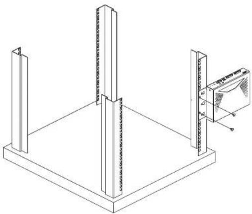
natural_image
Isometric line drawing of a structural frame with vertical supports and a close-up view of a wall-mounted device (no text or symbols)Note: These screws are not provided. We recommend that you use M5 x 12 Phillips Type I cross recessed type screws.
Chapter 2. Hardware Setup
Wall Mounting
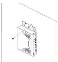
For convenience the Transmitter can be mounted to a wall.
- Using the screws provided in the Mounting Kit, screw the mounting bracket into the bottom of the Transmitter as show in the diagram below:
- Use the center hole to screw the bracket to a secure wall surface.
natural_image
Isometric line drawing of a device casing with ventilation grilles and ports (no text or symbols)Setting Up a Point-to-Point Installation
Setting up the KE6900 / KE6940 system in a point-to-point configuration is simply a matter of plugging in the cables.
Note: In a point-to-point configuration, no administrator setup is necessary.
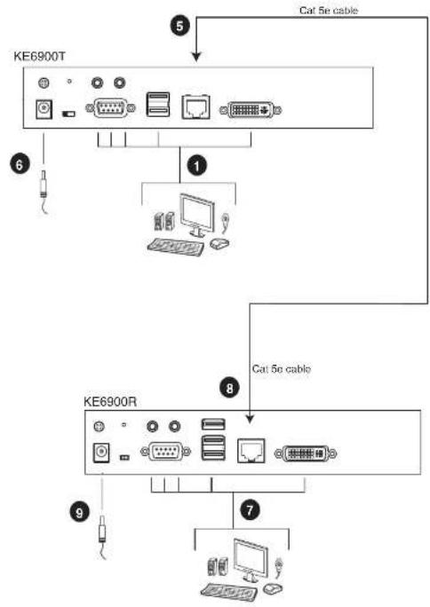
Make sure that all the equipment is powered off. Refer to the installation diagrams on the next two pages and do the following:
- On the Transmitter side, plug the mouse, keyboard, DVI monitor, microphone and speakers into the ports on the Console section of the KE6900T / KE6940T*. Each port is marked with an appropriate icon to indicate itself.
- Connect the USB KVM cable provided to the KVM Ports on the front of the KE6900T / KE6940T.
- Connect the other end of the USB KVM cable to the keyboard, video, mouse, speaker and microphone ports on the computer.
- For control of serial devices, connect the RS-232 serial port on the Transmitter to a serial port on the computer.
- Connect a Cat 5e cable to the KE6900T / KE6940T's LAN port.
- Plug the power adapter into an AC source; and plug the other end into the KE6900T / KE6940T's Power Jack.
- On the Receiver side, plug the mouse, keyboard, DVI monitor, microphone, and speakers into the ports on the Console section of the KE6900R / KE6940R*.
- Connect the other end of the Cat 5e cable to the KE6900R / KE6940R's LAN port.
- Plug the second power adapter into an AC source; and plug the other end into the KE6900R / KE6940R's Power Jack.
- Power on the computer.
Note: 1. If installing the KE6940 with two DVI monitors, connect the second DVI monitor and KVM DVI cable into the additional ports on the KE6940 and computer.
Chapter 2. Hardware Setup
Point-to-Point Installation 1 of 2
flowchart
graph TD
    A["KE6900T"] --> B["1"]
    B --> C["Computer"]
    B --> D["Router"]
    E["KE6900R"] --> F["7"]
    F --> G["Computer"]
    F --> H["Router"]
    I["5"] --> J["Cat 5e cable"]
    K["6"] --> L["Switch"]
    M["8"] --> N["Cat 5e cable"]
    O["9"] --> P["Switch"]
    Q["7"] --> R["Computer"]
KE6900 / KE6940 User Manual
Point-to-Point Installation 2 of 2
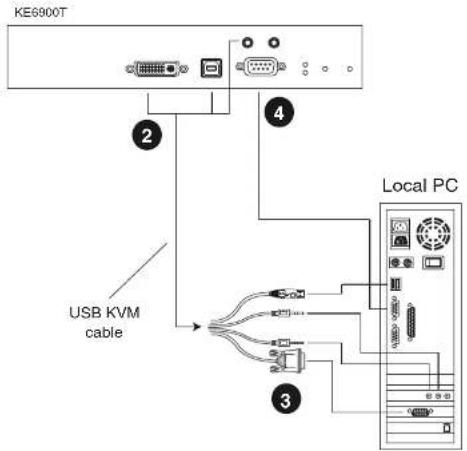
Note: The serial port on the Transmitter (shown above) connects to the computer; the serial port on the Receiver (not shown) connects to a serial device (optional).
Setting Up a LAN Installation
Setting up the units on a network allows point-to-point, point-to-multipoint, and multipoint-to-multipoint computer to console operation by connecting multiple KE6900 / KE6940 devices on the same TCP/IP LAN.
Note: 1. The units are preconfigured with factory-default network settings. If you install only one set of KE6900 / KE6940 units, you do not need to change these default network settings. See Default IP Addresses, page 24, for further details.
2. In a network setup with multiple units, each Transmitter and Receiver must be configured with a unique IP address. See Network Configuration, page 23, for further details.
3. We recommended using 1000Mbps Gigabit Ethernet switches between KE69xx devices installed on different LAN segments. 10/100Mbps switches might cause poor performance.
4. In multipoint configurations, the IGMP and flow control function of your network switches/hubs must be enabled to avoid the deterioration of data throughput. To ensure functionality use a layer 3 switch that supports IGMP queries.
5. If your network uses cascaded switches, please check to ensure the data throughput is sufficient.
6. To get the best performance, we suggest creating a private network for KE69xx devices, as they are bandwidth-intensive devices.
Make sure that all the equipment is powered off. Refer to the installation diagram on the following page, and do the following:
- On the Transmitter side, plug the mouse, keyboard, DVI monitor, microphone and speakers into the ports on the Console section of the KE6900T / KE6940T*. Each port is marked with an appropriate icon to indicate itself.
- Connect the USB KVM cable provided to the KVM Ports on the front of the KE6900T / KE6940T.
- Connect the other end of the USB KVM cable to the keyboard, video, mouse, speaker and microphone ports on the computer.
KE6900 / KE6940 User Manual
- Use a Cat 5c cable to connect the KE6900T / KE6940T's LAN port to the local area TCP/IP network.
- Plug the power adapter into an AC source; and plug the other end into the KE6900T / KE6940T's Power Jack.
- On the Receiver side, plug the mouse, keyboard, DVI monitor, microphone, and speakers into the ports on the Console section of the KE6900R / KE6940R*.
- Use a Cat 5c cable to connect the KE6900R / KE6940R's LAN port to the local area TCP/IP network.
- Plug the second power adapter into an AC source; and plug the other end into the KE6900R / KE6940R's Power Jack.
- Use the OSD on the Receiver to configure the network settings for both devices (See Network Configuration, page 23).
- Repeat these steps for each Transmitter and Receiver you wish to install on the network.
- Power on the computer(s).
Note: 1. If installing the KE6940 with two DVI monitors, connect the second DVI monitor and KVM DVI cable into the additional ports on the KE6940 and computer.
2. A keyboard or mouse with special functions may need to use the USB ports for advanced features to work (see USB Mode, page 62).
Chapter 2. Hardware Setup
Network Installation Diagram 1 of 2
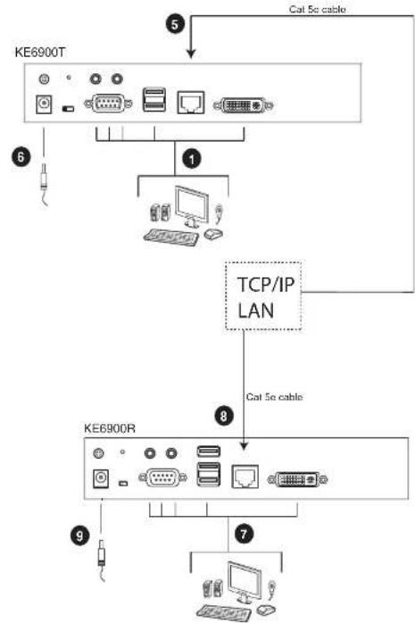
flowchart
graph TD
    A["KE6900T"] -->|Cat 5c cable| B["TCP/IP LAN"]
    C["KE6900R"] -->|Cat 5c cable| B
    D["Computer"] -->|1| B
    E["Switch"] -->|6| C
    F["Computer"] -->|7| G["Computer"]
KE6900 / KE6940 User Manual
Network Installation Diagram 2 of 2
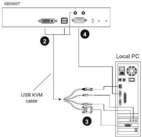
Note: The serial port on the Transmitter (shown above) connects to the computer; the serial port on the Receiver (not shown) connects to a serial device (optional).
Network Configuration
This section provides instructions to configure the network settings with a fixed IP address, subnet mask, and default gateway. To use the IP Installer to configure the IP address, see IP Installer, page 137.
Note: 1. Both devices are preconfigured with factory-default network settings. If you install only one set of KE6900 / KE6940 units, you do not need to change these default network settings. See Default IP Addresses, page 24, for further details.
2. In a network setup with multiple units, each KE6900T / KE6940T and KE6900R / KE6940R must be configured with a unique IP address. See Network Configuration, page 23, for further details.
3. We recommended using 1000Mbps Gigabit Ethernet switches between KE69xx devices installed on different LAN segments. 10/100Mbps switches might cause poor performance.
4. In multipoint configurations, the IGMP and flow control function of your network switches/hubs must be enabled to avoid the deterioration of data throughput. To ensure functionality use a layer 3 switch that supports IGMP queries.
5. If your network uses cascaded switches, please check to ensure the data throughput is sufficient.
6. To get the best performance, we suggest creating a private network for KE69xx devices, as they are bandwidth-intensive devices.
To configure the network settings, do the following:
- Setup the hardware and connect the Transmitter and Receiver to the local area network (See Setting Up a LAN Installation, page 19, for details).
- From the Receiver, tap the Scroll Lock key twice to invoke the OSD.
- Select the User Station or Transmitter from the Sidebar menu.
- Enter the password and click Configure.
The default password is: password.
- From the Network tab select Set IP address manually and enter the
KE6900 / KE6940 User Manual
Note: See Default IP Addresses, page 24, for the preconfigured factory-default settings.
Subnet Mask – sets the subnet mask for the KE6900 / KE6940. Key in a valid subnet mask value.
Note: The default setting is 255.255.255.0
Default Gateway—sets the default gateway for the KE6900 / KE6940. Key in a valid default gateway.
- Click Save.
Return
To exit the OSD, press [Esc] on the keyboard, click Logout; tap the Scroll Lock key twice; or return to the OSD main page and press the front panel OSD pushbutton (Receiver only).
At this point the User Station can connect to the Transmitter to access the remote computer (see Connecting, page 38 for instructions).
Default IP Addresses
The preconfigured factory-default IP addresses for the KE6900 / KE6940 units are as follows:
KE6900T/KE6940T-192.168.0.61
KE6900R / KE6940R - 192, 168, 0, 60
Chapter 3
OSD Operation
Overview
This chapter provides instructions to configure and operate the KE6900 / KE6940 using the local On Screen Display (OSD). To configure the network settings with the OSD, see Network Configuration, page 23.
LED Display
Both the Transmitter and Receiver have front panel LEDs to indicate their operating and power status, as explained in the table below:
| LED Indication | |
| LAN | Lights when LAN is connected.Off when LAN is not connected.Blinks when Ethernet is active.Lights Green to indicate high network bandwidth (ultra-high video) is in use. |
| Power | OFF when power is off.Lights Blue when the unit is powered on |
| Local | Lights Green to Indicate the Transmitter has KVM focus of the computer |
| Remote | Lights Green to Indicate the Receiver has KVM focus of the computer. |
Invoking the OSD
The On Screen Display (OSD) is a keyboard/mouse-driven application on the receiver used to configure the transmitter and receiver settings. Once the receiver has discovered the transmitter over a network* or direct Ethernet cable connection, you can use the OSD on the receiver to configure the transmitter's settings.
To invoke the OSD, press the OSD pushbutton on the front of the receiver, or from the keyboard tap the Scroll Lock key twice. The OSD main page will appear (see OSD Interface, page 27).
To exit the OSD, press |Esc| on the keyboard; click Logout; tap the Scroll Lock key twice; or return to the OSD main page and press the OSD pushbutton on the front of the receiver. The OSD disappears and the computer desktop screen or the System Login prompt is displayed.
OSD Interface
After you invoke the OSD, the main page appears:
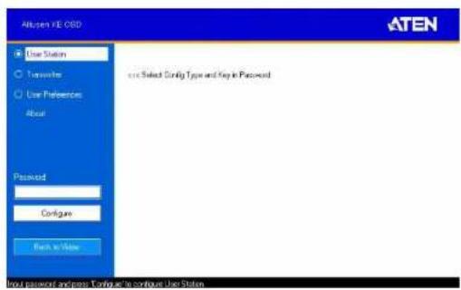
Note: A password is required to enter the OSD. The default password is: password. For security purposes, we recommend you change this to something unique.
The OSD components are described in the table, below:
| No. Item Description | |
| 1 User Station(Receiver) | Select this radio button, enter a password, and click Configure to enter the User Station Configuration screen. |
| 2 Transmitter Select this | radio button, enter a password, and click Configure to enter the Transmitter Configuration screen.Note: Receiver must first discover the transmitter over the network for this option to be available. |
| 3 User Preferences Select | this radio button, enter a password, and click Configure to enter the User Preferoncos screen. |
| 4 About About provides information regarding the OSD version. | |
| 5 Password Input the OSD | password and click Configure to enter the selected configuration screen. See note for password. |
User Station Configuration
When you select the User Station radio button and click Configure to login, the Network tab appears:
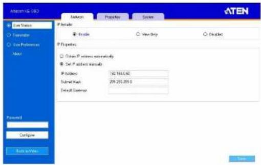
Network
The Network tab allows you to configure the User Station's IP address settings:
| Item Description | |
| IP Installer The IP | Installer is an external Windows-based utility for assigning an IP address to the device. Click one of the radio buttons to select Enable, View Only, or Disable for the IP Installer utility. See IP Installer, page 137 for instructions.Note: For security, we strongly recommend that you set this to View Only or Disable after each use. |
| Network Configuration | For dynamic IP address assignment (DHCP), select the Obtain IP address automatically radio button.To specify a fixed IP Address, Subnet Mask, and Default Gateway select the Set IP address manually radio button and fill in the fields with values appropriate for your network.For help configuring network settings with the OSD. |
Properties
The Properties tab allows you to configure the User Station's extender settings:
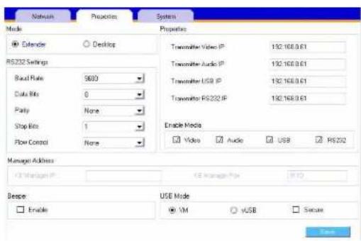
| Item Description | |
| Mode | Select Extender mode for simple one-to-one (Transmitter to User Station) setups that are managed with the Receiver's OSD menu.Select Desktop/Matrix mode to manage devices and connections from the Matrix Manager web GUI. This mode is for advanced administration of Transmitter to User Station connections. (See Target Connections, page 74) |
| Properties | If you selected Extender mode (above) set the Transmitter IP address for the User Station's Video, Audio, USB, and RS232 source signals.If you selected Desktop/Matrix mode (above) the Properties will be grayed out. Use Targets to configure the Transmitter connections. (See Target Connections, page 74) |
KE6900 / KE6940 User Manual
| Item Description | |
| RS232 Settings Configure the serial device settings for the User Station. The default settings are: Baud Rate: 9600 Parity: None Data Bits: 8 bits Stop bits: 1 bit Flow Control: None | |
| Enable Media Select which type of media the User Station can stream from Transmitters: Video, Audio, USB, and RS232. | |
| Manager Address | Set the IP address and Port number of the computer running the Matrix Manager software. The default port number is 9110. |
| Beeper Check this box to allow the User Station to beep when configuration changes are made to it. | |
| USB Mode Select the type of USB device you will connect to the USB ports: vUSB: Use this option to plug USB peripherals into the USB ports. This option also allows a keyboard and mouse with special functions to plug into the USB ports for console use. Use this only if the special functions of the keyboard or mouse are required but do not work when plugged into the console ports. When the keyboard and mouse are plugged into the USB ports, they will not work within the OSD menus. To work within the OSD menus, the keyboard and mouse must be plugged into the console ports. VM (Virtual Media): Only select this option if you are plugging a USB disk into the USB ports. This will give you the highest data transfer speeds but will not allow other USB devices plugged into the USB ports to work. Secure: Check this box to encrypt USB drives plugged into the USB ports. | |
After entering the information, click Save.
Chapter 3. OSD Operation
System
The System tab allows you to configure the User Station's general settings:
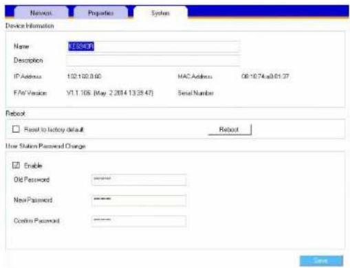
| Item Description | |
| Device Information | Enter the Name, Location, and Description of the User Station. It also displays the IP Address, MAC Address, F/W Version, Serial Number, and Model Number of the User Station. |
| Reboot | Check the box and click Reboot to reset the User Station's settings back to the factory default. All custom settings will be lost. |
| User Station Password Change | Check Enable to require a password for access to the User Station's OSD configuration screen. Enter the Old Password, enter a New Password, and confirm the new password in the Confirm Password box. |
After entering the information, click Save.
Transmitter Configuration
When you select the Transmitier radio button and click Configure to login, the Network tab appears:
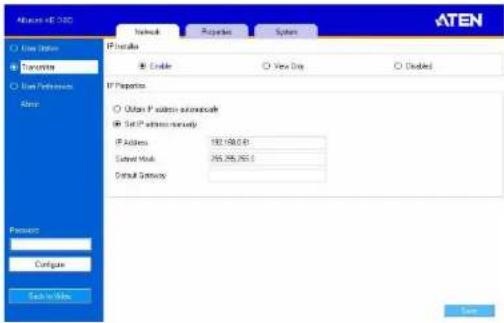
Network
The Network tab allows you to configure the Transmitter's IP address settings:
| Item Description | |
| IP Installer The IP | Installer is an external Windows-based utility for assigning an IP address to the device. Click one of the radio buttons to select Enable, View Only, or Disable for the IP Installer utility. See IP Installer, page 137 for instructions.Note: For security, we strongly recommend that you set this to View Only or Disable after each use. |
| Network Configuration | For dynamic IP address assignment (DHCP), select the Obtain IP address automatically radio button.To specify a fixed IP Address, Subnet Mask, and Default Gateway select the Set IP address manually radio button and fill in the fields with values appropriate for your network.For help configuring network settings with the OSD. |
Properties
The Properties tab allows you to configure the Transmitter's extender settings:
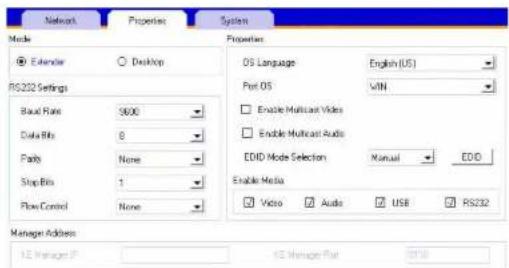
| Item Description | |
| Mode | Select Extender mode for simple one-to-one (Transmitter to User Station) setups that are managed with the Receiver's OSD menu.Select Desktop/Matrix mode to manage devices and connections from the Matrix Manager web GUI. This mode is for advanced administration of Transmitter to User Station connections. (See Target Connections, page 74) |
KE6900 / KE6940 User Manual
| Item Description | |
| Properties | Port OS: Use the drop-down menu to select the operating system of the computer connected to the Transmitter.OS Language: Use the drop-down menu to select the operating system language of the computer connected to the Transmitter.Enable Multicast Video: Check this box to allow a broadcast of the Transmitter's video signal to be sent out to multiple User Stations.Enable Multicast Audio: Check this box to allow a broadcast of the Transmitter's audio signal to be sent out to multiple User Stations.EDID Mode Selection: EDID contains a display's basic information and is used by the source device to utilize the best resolution across different monitors. Select how you want the source device to acquire the display's EDID:Default: EDID is set to the default ATEN configuration.Auto: Checks the EDID of all connected displays and uses the best resolution for all displays.Manual: Manually set the EDID configuration from the Connections Page (see page 39).Remix: Checks the EDID of all connected displays and the source device uses the best common resolution for all displays. |
| Enable Media | Select which type of media the Transmitter can stream to User Stations: Video, Audio, USB, and RS232. |
| RS232 Settings Configure the serial device settings for the Transmitter. The default settings are:Baud Rate: 9600Parity: NoneData Bits: 8 bitsStop bits: 1 bitFlow Control: None | |
| Manager Address | Set the IP address and Port number of the computer running the Matrix Manager software. The default port number is 9110. |
Chapter 3. OSD Operation
| Item Description | |
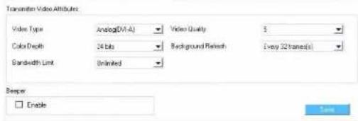
| Transmitter Video Attributes | To set the Transmitter's video settings:Video Type: Select the DVI video connector being used by the display: Digital (DVI-D) or Digital (DVI-I).Color Depth: Select the number of bits to use for the color depth: 24, 16, or 8. This is the number of bits used to describe the color of a single pixel. A bit depth determines the number of colors that can be displayed at one time.Bandwidth Limit: Select the maximum bandwidth that the Transmitter can use to transmit video over the network. A lower bandwidth setting transmits lower quality video; a higher bandwidth setting sends higher quality video but this can affect network speed.Video Quality: Select the video quality to use. 5 is the highest video quality, and 1 is the lowest video quality. Options are: 1~5.Background Refresh: Sets how often the Transmitter refreshes the background image on the connected display. Options are to refresh every 256,128, 64, 32,16, or 0 frames. |
| Beeper Check this box to allow the device to beep every time a configuration change is made. | |
| Occupy Timeout Set a time threshold for devices whose Access Mode has been set to Occupy (see Allowed Access Mode, page 100). If there is no activity from the User Station occupying the port for the amount of time set here, the User Station is timed out and the port is released. The first User Station to send keyboard or mouse input after the port has been released gets to occupy the port. Input a value from 1 to 240 seconds. | |
After entering the information, click Save.
System
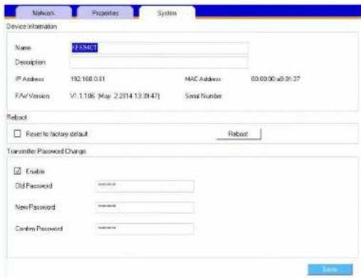
The System tab allows you to configure the Transmitter's general settings:
| Item Description | |
| Device Information | Enter the Name, Location, and Description of the Transmitter. It also displays the IP Address, MAC Address, F/W Version, Serial Number, and Model Number of the Transmitter. |
| Reboot | Check the box and click Reboot to reset the Transmitter's settings back to the factory default. All custom settings will be lost. |
| Transmitter Password Change | Check Enable to require a password for access to the Transmitter's OSD configuration screen. Enter the Old Password, enter a New Password, and confirm the new password in the Confirm Password box. |
After entering the information, click Save.
User Preferences
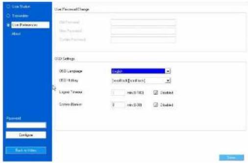
When you select the User Preferences radio button and click Configure to login, the configuration screen appears:
| Item Description | |
| User Password Change | This section allows you to change the OSD password:1. Key in the old password in the Old password field.2. Key in the new password in the New password field.3. Key in the new password again in the Confirm password field. |
| OSD Language Click the drop-down menu to select the language you want to use for OSD sessions. Choices are: English, Chinese (Simplified), Chinese (Traditional), Japanese, Korean, Dutch, French, Spanish, Portuguese, and Russian. | |
| OSD Hotkey Select the hotkey combination to invoke the OSD screen. | |
| Logout Timeout If there is no user input for the amount of time set with this function, the user is automatically logged out of the OSD. A login is necessary before the OSD can be accessed again. | |
Connecting
If the User Station is set to Extender mode, the video screen of the remote computer will appear automatically when you exit the OSD (tap the Scroll Lock key twice). In Desktop/Matrix mode you will see the System Login screen, which provides access to the Connection Page by entering a username and password:
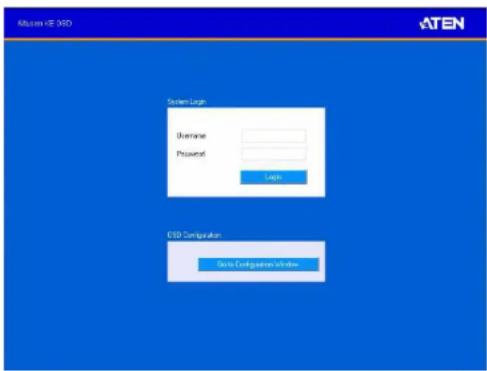
Note: 1. The administrator account can be used to log in for the first time. Username: administrator | Password: password. For security purposes, we recommend you change this to something unique (see User Management, page 85).
2. If the User Station does not require a login, click Login to system (see Login Required, page 62).
3. For information about Extender and Desktop/Matrix modes see Mode, page 29.
Chapter 3. OSD Operation
Connections Page
After you have successfully logged in the Connection Page appears:
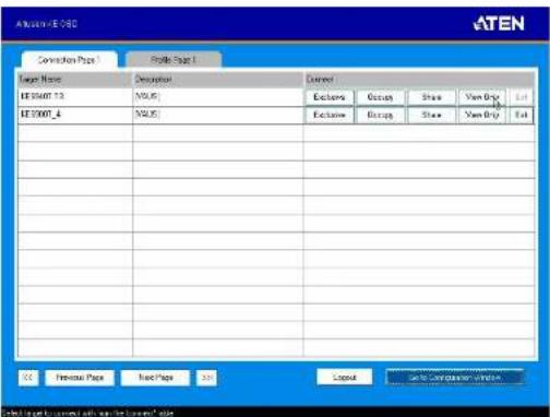
The Connection Page components are described in the table, below:
No. Item Description
| 1 Target Name Lists the Target connections available for the User Station. A Target is a defined connection to Transmitters, created in the Device Management tab of the Matrix Manager (see Targets, page 75). | |
| 2 Description This field provides a description of the Target, entered when it was created. |
KE6900 / KE6940 User Manual
| No. Item Description | |
| 3 Connect To connect the User | Station to a Target, click the access type:Exclusive: The first User Station to access the Target has exclusive control over the Target. No other User Stations can view the Target. The Timeout function does not apply to this setting.Occupy: The first User Station to access the Target has control over the Target. However, additional User Stations may view the Target's video display. If the User Station controlling the Target is inactive for longer than the time set in the Timeout box, control is transferred to the first User Station to move the mouse or strike the keyboard.Share: Can simultaneously share control over the Target. Input from the User Stations is placed in a queue and executed chronologically.View Only: User Station connects with view only access to the Targets video display. |
| 4 Next Page Use this button to | navigate to the next page if there are more Targets than can be listed on one page. |
| 5 Previous Page Use this button to navigate to the previous page if there are more Profiles than can be listed on one page. | |
| 6 Manual EDID If the EDID is set to Manual, the Manual EDID button appears. Click Manual EDID to adjust the EDID setting locally. When the Operation Successful box appears, click OK. (See Properties, page 34, for details) | |
| 7 Logout Click this button to log out of the Connection Page. | |
| 8 Go to Configuration Window | Click this button to return to the main OSD screen. |
Chapter 3. OSD Operation
Profile Page
Click the Profile Page tab and the following screen appears:
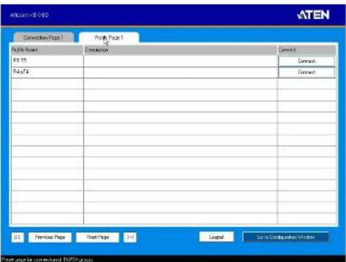
The Profile Page components are described in the table, below:
| No. Item Description | |
| 1 Profile Name Lists the Profiles | available. Profiles give User Stations access to Targets and allow you to push the connection. |
| 2 Description The field provides | a description of the Profile that was entered when it was created. |
| 3 Connect Click Connect and the | the User Station will re-connect with the settings of that Profile (seeProfiles, page 81). |
| 4 Next Page Use this button to | navigate to the next page if there are more Profiles than can be listed on one page. |
| 5 Previous Page Use this button | to navigate to the previous page if there are more Profiles than can be listed on one page. |
This Page Intentionally Left Blank
Chapter 4
Matrix Manager Installation
Overview
The Matrix Manager is a browser based GUI that provides management of KE6900 / KE6940 devices over a network. Download and install the software to begin managing the KE6900 / KE6940 devices from a computer using a web browser.
Download
To download the Matrix Manager Lite software, do the following:
- Visit our website and click Support → Go to ATEN eService.
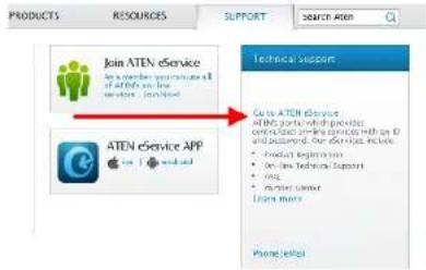
- Create an account and login to ATEN eService.
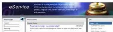
KE6900 / KE6940 User Manual
- Register the KE690x device(s) you have purchased.

- After you have registered the KE device(s), click Trial Software Download.
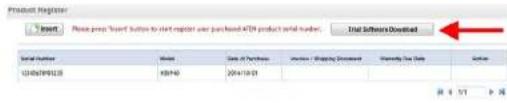
Note: The trial software includes full functions to setup and configure single device installations. The trial version will not expire. If you would like to purchase the advanced software, please contact your ATEN reseller.
- Click the software version you would like to download, then click Save.
| My Download > Trial Software Download | ||
| File Title | Tick Site | File Download |
| KE Matrix Manager Lite v1.2.113 (Linux version) | KE900 PKI KVM Over IP Extended introduction link (click download icon to download KE Matrix Manager Lite version) | |
| KE Matrix Manager Lite v1.2.113 (Windows version with user name) | KE900 PKI KVM Over IP Extended introduction link (click download icon to download KE Matrix Manager Lite version) | |
-
Unzip the Matrix_Manager_Lite.zip file and double click the *.exe file to start the installation.
-
Follow the instructions on the next page to install the software.
Matrix Manager Install
The following are instructions to install the full version of the Matrix Manager software. For software requirements, see Software, page 3.
- Insert the USB license key into a USB port on your computer.
- Double click the MatrixManagerSetup file to start the setup. When the Introduction screen appears, click Next.:
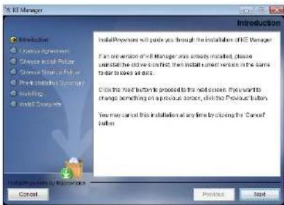
- The License Agreement appears:
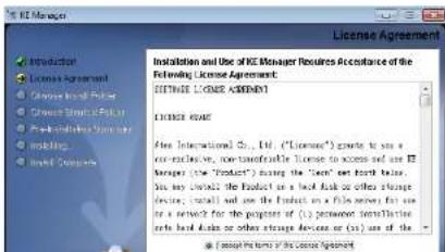
If you agree with the License Agreement, select I accept the terms of the license agreement, and click Next.
- The Choose Install Folder screen appears:
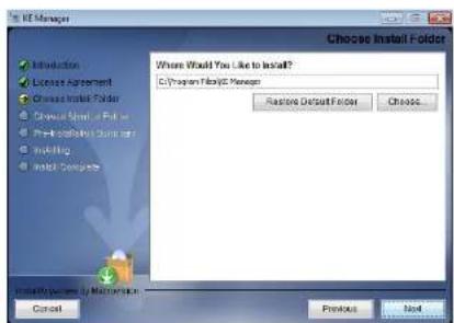
Select where you would like to install the program, and click Next.
- The Choose Shortcut Folder screen appears:
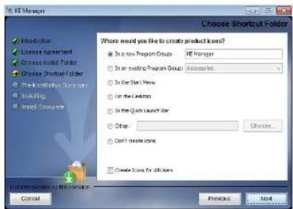
Chapter 4. Matrix Manager Installation
- The Pre-Installation Summary screen appears:
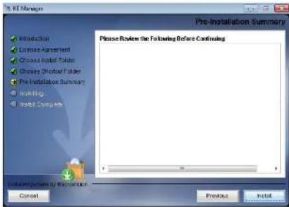
Confirm the settings you've selected. If you want to make a change click Previous to go back, or click Install to begin the software installation.
- When the process is done, the Install Complete screen appears:
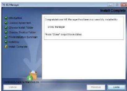
图 1.2
This Page Intentionally Left Blank
Chapter 5
Browser Operation
Overview
The Matrix Manager software can be accessed through most standard web browsers. Once users log in and are authenticated, the browser GUI comes up. This chapter explains the login procedure and web browser components.
Logging In
To log into the Matrix Manager, do the following:
- Open the browser and specify the IP address of the computer installed with the Matrix Manager software, in the browser's URL location bar.
Note: If the administrator has configured the HTTP or HTTPS port setting as something other than the default, you must include http://or https:// before the IP address, and specify the port number along with the IP address. For example:
https://192.168.1.20:8443
Where 8443 is the https port number, and a colon is inserted between it and the IP address.
- If a Security Alert box appears, accept the certificate – it can be trusted (See Trusted Certificates, page 138 for details). The Login page appears:
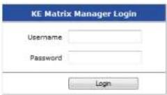
- Enter the Username and Password, and click Login.
The Matrix Manager Main Page
After you have successfully logged in, the web browser's main page appears:
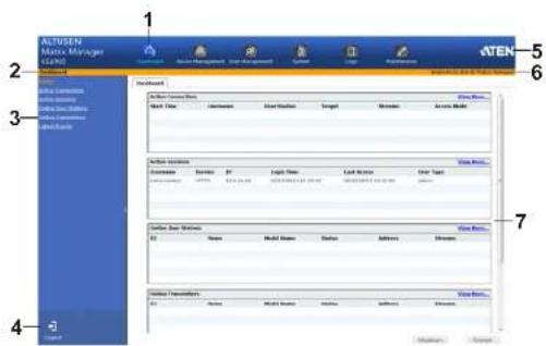
Web Components
The web components are described in the table, below:
| No. Item Description | ||
| 1 Tab Bar The tab bar contains | the Matrix Manager's main operation categories: Dashboard, Device Management, User Management, System, Logs, and Maintenance. | |
| 2 Menu Bar The menu bar contains operational sub-categories that pertain to the item selected in the tab bar. | ||
| 3 Sidebar The Sidebar provides | a tree view and listing of items that relate to the various tab bar and menu bar selections. Clicking an item in the Sidebar brings up a page with the details that are relevant to it. | |
| 4 Logout Click this button to log out of your Matrix Manager web session. | ||
| 5 ATEN Logo Click this button to open a new browser window that opens on the ATEN website. | ||
Tree View Considerations
On some pages there will be a sidebar menu with options that can be expanded:
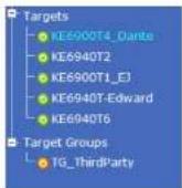
A plus (+) sign in front of an item means that there are additional items nested inside of it. Click the plus sign to expand the view and show the nested items.
- The plus sign changes to a minus sign (-)when an item is expanded. Click the minus sign to collapse the view and hide the nested items.
- For devices, if the device is on line, its icon is in GREEN; if it is off line, its icon is ORANGE.
The Tab Bar
The functions associated with each of the tabs are explained in the table below:
| Icon Function | |
| Dashboard: The Dashboard is used to view information about current connections, sessions, and device events. The first page provides an overview and the sidebar provides a link to view details about each section. The Dashboard is discussed on page 53. | |
| Device Management: The Device Management page is used to configure and control the overall operation of the devices added to the Matrix Manager. Device Management is discussed on page 57. | |
| User Management: The User Management page is used to create and manage Users and Groups. It is also used to assign permissions to them. User Management is discussed on page 115. | |
| System: The System page is used to configure the Matrix Manager's global settings and setup ANMS authorization and authentication. The System page is discussed on page 98. | |
| Logs: The Log page displays the contents of the log file. The Log page is discussed on page 111. | |
| Maintenance: The Maintenance page is used to install firmware; backup and restore configuration information, install certificates, and set preferences. The Maintenance page is discussed on page 115. | |
Icon Function
Chapter 6 Dashboard
Overview
The Dashboard tab is used to view events about connections, sessions, and online devices. The Home page provides an overview of the information provided in each section. The Sidebar menu provides a link to each section for a more detailed view of each item.
The Dashboard opens on the Home page, as shown here:
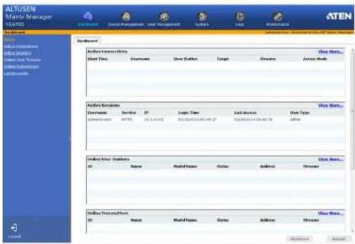
At the bottom of the page, click Shutdown ^® to stop the KeManager service; or Restart to stop/restart the service. Both options will logout all user web sessions.
Note: Clicking Shutdown stops the KeManager service, and web sessions will not be available until the KeManager service is restarted.
Active Connections
The Active Connections page lets an administrator see the active Target connections (User Stations connected to Transmitters) and provides information about each of their sessions.
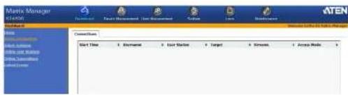
The meanings of the headings at the top of the page are straightforward.
- Start Time refers to the date/time the connection between the User Station and Transmitter began.
- Username refers to the user that logged into the User Station to establish the connection.
- User Station refers to the Receiver that is being used to access the Target connection.
• Target refers to the defined Transmitter connections in use by the User Station.
• Streams refers to the type of source the connection is streaming: Video, Audio, USB, or Serial. - Access Mode refers to the type of access (Exclusive, Occupy, Share, View only) that the User Station is connecting with.
Active Sessions
The Active Sessions page lets the administrator see all of the users logged into the Matrix Manager and provides information concerning the "who, where and when" of each session.

Online User Stations
The Online User Stations page lets the administrator see all of the Receivers that are currently available on the network and provides information about each device.

The meanings of the headings at the top of the page are straightforward.
• ID refers to the identification number assigned by the system.
- Name refers to the name entered on the User Stations's System page.
• Model Name refers to the Receiver model number.
- Status refers to the User Station's online status.
- Address refers to the IP address of the User Station.
- Streams refers to the source type that the User Station is configured to stream: Video, Audio, USB, and Serial.
Online Transmitters
The Online Transmitters page lets the administrator see all of the Transmitters that are currently available on the network and provides information about each device.

The meanings of the headings at the top of the page are straightforward.
• ID refers to the identification number assigned by the system.
- Name refers to the name entered on the Transmitter's System page.
• Model Name refers to the Transmitter model number.
- Status refers to the Transmitter's online status.
Latest Events
The Latest Events page lets the administrator see the most recent Dashboard events that relate to the current connections and sessions, and provides details about each.
Latent Events
| Time | User | Severity | Device | Log Information |
| 01/26/2014 14:00:33 | Information | Session created(Sessioned)*****(10.3.41.67). | ||
| 01/26/2014 14:01:23 | administration | Information | User logit succeeded(username-administrator). | |
| 01/26/2014 14:02:00 | Error | Cannot find the IE authentication key. | ||
| 01/26/2014 15:01:14 | Information | Session created(Sessioned)*****(10.3.41.67). | ||
| 01/26/2014 15:48:13 | administration | Information | User logit succeeded(username-administrator). | |
| 01/26/2014 15:18:38 | Error | Cannot find the IE authentication key. | ||
| 01/26/2014 15:35:47 | Error | Cannot find the IE authentication key. | ||
| 01/26/2014 15:06:43 | administration | Information | User logit(username-administrator). | |
| 01/26/2014 15:09:43 | Information | Session terminated normally(Sessioned)*****(10.3.41.67). | ||
| 01/26/2014 15:09:43 | administration | Information | User logit(username-administrator). | |
| 01/26/2014 15:56:13 | Information | Session created(Sessioned)*****(10.3.41.67). | ||
| 01/26/2014 15:58:17 | administration | Information | User logit succeeded(username-administrator). | |
| 01/26/2014 15:52:23 | Error | Cannot find the IE authentication key. | ||
| 01/26/2014 15:51:30 | Error | System will boost in 10 seconds. | ||
| 01/26/2014 15:51:34 | Information | Session created(Sessioned)*****(10.3.41.67). | ||
| 01/26/2014 15:51:34 | administration | Information | User logit succeeded(username-administrator). | |
| 01/26/2014 15:49:03 | Error | Cannot find the IE authentication key. | ||
| 01/26/2014 15:47:13 | administration | Information | User logit succeeded(username-administrator). | |
| 01/26/2014 15:47:13 | Information | Session created(Sessioned)*****(10.3.41.67). | ||
| 01/26/2014 15:47:13 | administration | Information | User logit(username-administrator). | |
| 01/26/2014 15:47:13 | Information | Session terminated normally(Sessioned)*****(10.3.41.67). |
The meanings of the headings at the top of the page are straightforward.
• Time refers to the date and time that the event occurred.
- User refers to the username that the event relates to. If no username appears, the event is general system information.
- Severity refers to the event's severity type: Information, Error, or Warning
• Device refers to the Transmitter or User Station that relates to the event. If no device is listed the event refers to the Matrix Manager.
- Log Information provides detailed information about each event.
Chapter 7
Device Management
Overview
The Device Management tab contains four menu bar items: User Stations, Transmitters, Targets, and Profiles. Each page provides a way to add, configure, and managed Transmitters, Receivers, and connections. Before Transmitters and Receivers can be added they must be connected to the network with an IP address.
The Device Management tab opens on the User Stations page, as shown here:
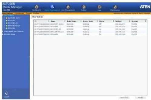
The User Stations page allows you to add, configure, and delete Receivers. The Sidebar provides three menu options: User Stations, Unmanaged User Stations, and Rx Video Group. User Stations are Receivers that have been added to the Matrix Manager. Unmanaged User Stations are Receivers on the network that haven't been added to the Matrix Manager. For the Matrix Manager to discover a Receiver, it must be connected to the local network with an IP address. Rx Video Group lists Transmitters that have been grouped to share the video from one computer to multiple User Stations.
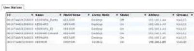
Click User Stations from the menu bar and the following screen appears:
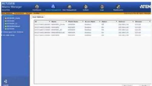
The main page provides an overview of each User Station. The Sidebar provides a link with a more detailed view of each.
The meanings of the headings at the top of the page are straightforward.
• ID refers to the identification number assigned by the system.
- Name refers to the name entered on the User Stations's System page.
• Model Name refers to the Receiver model number
- Access Mode refers to the User Station's mode set in the Properties.
- Status refers to the User Station's online status.
Adding a User Station
To add a User Station, do the following:
- From Unmanaged User Stations, select a User Station and click Add in:

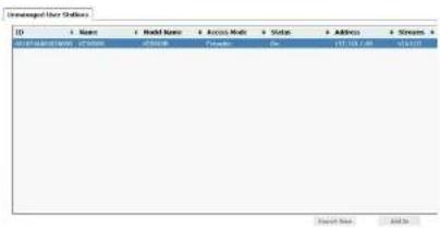
or click Search New:
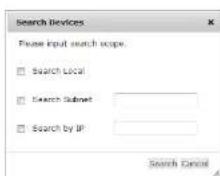
You can search for a device by Local, Subnet, or IP address. Select a scope, enter the information and click Search.
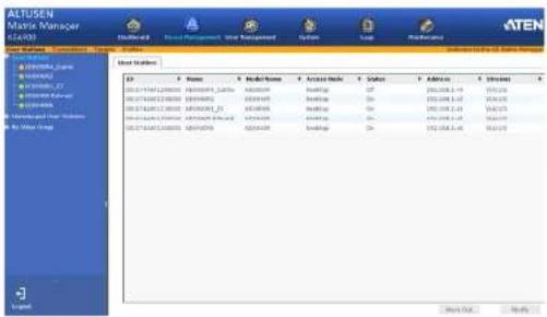
- Once added, the User Station appears on the User Stations main page and in Sidebar menu:

Configuring a User Station
A User Station's settings can be modified from the User Stations main page. Changes that are saved are updated on the User Station device across the network. To configure a User Station:
- Select a User Station and click Modify.
- The Network tab appears with the User Station's IP address settings:
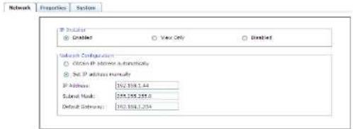
Item Description
IP Installer The IP Installer is an external Windows-based utility for assigning IP addresses to the device. Click one of the radio
| Item Description | |
| Network Configuration | For dynamic IP address assignment, select the Obtain IP address automatically radio button.To specify a fixed IP Address, Subnet Mask, and Default Gateway select the Set IP address manually radio button and fill in the fields with values appropriate for your network.For information to configure the network settings locally on the device see Network Configuration, page 23. |
- Click the Properties tab to configure the User Station's properties:
Network Properties System
| Media | ||
| ○ Extended | ● Display | |
| F0226 240.0pp | ||
| Each Rate | 1600 | M |
| Falls | None | M |
| Data Bits | Data | M |
| Stop Bits | List | M |
| Data Control | None | M |
Item Description
| Mode | Select Extender mode for simple one-to-one (Transmitter to User Station) setups that are managed with the Receiver's OSD menu.Select Desktop/Matrix mode to manage devices and connections from the Matrix Manager. This mode is for advanced administration of Transmitter to User Station connections. (See Target Connections, page 74) |
| Properties | If you selected Extender mode (above) set the Transmitter IP address for the User Station's Video, Audio, USB, and RS232 source signals.If you selected Desktop/Matrix mode (above) the Proportions will be grayed out. Use Targets to configure the Transmitter connection (See Target Connections, page 74) |
KE6900 / KE6940 User Manual
| Item Description | |
| RS-232 Settings Configure the settings for the serial device the User Station will be connecting to. The default settings are: Baud Rate: 9600 Parly: None Data Bits: 8 bits Stop bits: 1 bit Flow Control: None | |
| Enable Media Select which source type the User Station can stream : Video, Audio, USB, and RS232. | |
| Manager Address | Set the IP address and Port number of the computer running the Matrix Manager software. The default port number is 9110. |
| Login Required Check this box to require a username and password on the User Station's OSD to access the Connection Page (see page 38). Note: WARNING! If you uncheck Login Required you must select an Anonymous User in Global Settings. Otherwise a system login error may occur on the User Station's OSD. (See User Station Login Settings, page 100) | |
| Beeper Check this box for the Receiver to beep when configuration changes are made. | |
| USB Mode Select the type of USB device you will connect to the USB ports: vUSB: Use this option to plug USB peripherals into the USB ports. This option also allows a keyboard and mouse with special functions to plug into the USB ports for console use. Use this only if the special functions of the keyboard or mouse are required but do not work when plugged into the console ports. When the keyboard and mouse are plugged into the USB ports, they will not work within the OSD menus. To work within the OSD menus, the keyboard and mouse must be plugged into the console ports. VM (Virtual Media): Select this option only if you are plugging a USB disk drive (including USB HDD/optical disk) into the USB ports. This will give you the highest data transfer speeds but will not allow other USB devices to work when plugged into the USB ports. Secure: Check this box to encrypt USB disk drives plugged into the USB ports. | |
- Click the System tab to configure the general settings:
Network Properties System
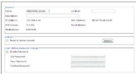
| Item Description | |
| General | Enter the Name, Location, and Description of the User Station. This section also displays the User Station's IP Address, MAC Address, F/W Version, Serial Number, and Model Number. |
| Reboot | Check the box and click Reboot to reset the User Station's settings back to the factory default. All custom settings will be lost. |
| User Station Password Change | Check Enable to require a password to access the User Station's OSD configuration screens (see page 27). Enter the Old Password, enter a New Password, and confirm the new password in the Confirm Password box. |
- After entering the information, click Save.
Deleting a User Station
To delete a User Station:
- Select the User Station you want to delete.
- Click Move Out.
Rx Video Group
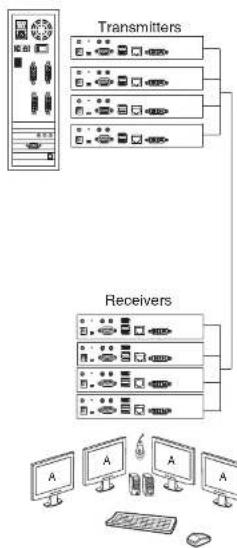
Creating an Rx Video Group allows you to cascade up to four Transmitters connected to separate video cards on one computer and share the video with four User Stations – while giving the first User Station keyboard and mouse access. The image below provides an example of the setup without the actual physical connections or possible device connections.
flowchart
graph TD
    A["Transmitters"] --> B["Computer Monitor"]
    C["Receivers"] --> D["Computer Monitor"]
    B --> E["Computer 1"]
    B --> F["Computer 2"]
    B --> G["Computer 3"]
    B --> H["Computer 4"]
    B --> I["Computer 5"]
    B --> J["Computer 6"]
    B --> K["Computer 7"]
    B --> L["Computer 8"]
    B --> M["Computer 9"]
    B --> N["Computer 10"]
    B --> O["Computer 11"]
    B --> P["Computer 12"]
    B --> Q["Computer 13"]
    B --> R["Computer 14"]
    B --> S["Computer 15"]
    B --> T["Computer 16"]
    B --> U["Computer 17"]
    B --> V["Computer 18"]
    B --> W["Computer 19"]
    B --> X["Computer 20"]
- Connect one Transmitter's - console & KVM ports to their respective device (keyboard/mouse/computer).
- Setup the Receivers as you normally would. All Receivers can have a keyboard and mouse but only one (Video 1) can work on the computer for the group.
- Note the Receiver and Transmitter with keyboard and mouse access (to the computer) so they can be set in the Rx Video Group (as Video 1) and in the Target (as KVM Transmitter).
Adding an Rx Video Group
- Add the User Stations (Adding a User Station, page 59) and Transmitters (Adding a Transmitter, page 68) to the Matrix Manager.
- On the left Sidebar select Rx Video Group.
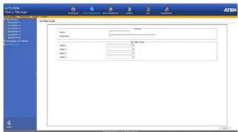
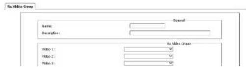
- Provide a Name and Description for the group.
KE6900 / KE6940 User Manual
- Use the Video 1 drop-down menu to select the Receiver that will have keyboard and mouse access to the computer.
Note: All Receivers can switch KVM access to other Transmitters but only Video 1 has keyboard and mouse access to the computer for the group.
- Use the Video 2, Video 3 and Video 4 drop-down menus to select the other Receivers for the group.
- Click Save. The group appears in the Sidebar.
- On the menu bar, go to Targets.
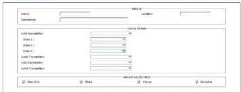
- Add a new Target.
Target Info Group Forecastion
-
Set the Source Stream to map the Transmitters to the Rx Video Group Receivers, as such: KVM Transmitter → Video 1; Video 2 → Video 2; Video 3 → Video 3; Video 4 → Video 4.
-
Use the KVM Transmitter drop-down menu to select the Transmitter connected to the computer's keyboard and mouse ports.
-
Use the Video 2, Video 3 and Video 4 drop-down menus to select the other Transmitters connected to the computer.
Use the Audio, USB and Serial drop-down menus to select the Transmitter for each source signal. The Transmitter selected sends the signal to the Receiver set with the same Video #. -
Configure the remaining Target settings (see Adding a Target, page 76).
-
Click Save.
Transmitters
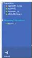
The Transmitters page allows you to add, configure, and delete Transmitters. The Sidebar provides two options: Transmitters and Unmanaged Transmitters. Unmanaged Transmitters are Transmitters on the network that haven't been added to the Matrix Manager. For the Matrix Manager to discover a Transmitter, it must be connected to the local network with an IP address.
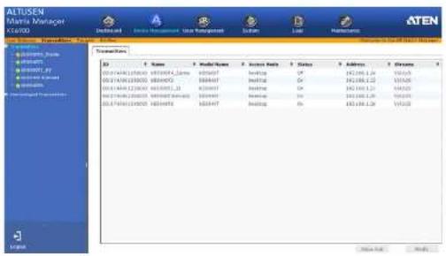
Click Transmitters from the menu bar and the following screen appears:
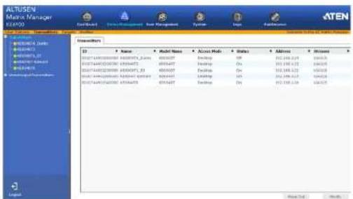
The main page provides an overview of each Transmitter. The Sidebar provides a link with a more detailed view of each.
The meanings of the headings at the top of the page are straightforward.
ID refers to the identification number assigned by the system.
- Name refers to the name entered on the Transmitter's System page.
- Model Name refers to the Transmitter's model number.
- Access Mode refers to the Transmitter's mode set in the Properties.
- Status refers to the Transmitter's online status.
- Address refers to the IP address of the Transmitter.
- Streams refers to the source type that the Transmitter is configured to
Adding a Transmitter
To add a Transmitter, do the following:
- From Unmanaged Transmitters, select a Transmitter and click Add in:
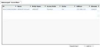
or click Search New:
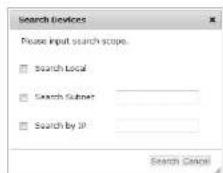
You can search for a device by Local, Subnet, or IP address. Select a scope, enter the information and click Search.
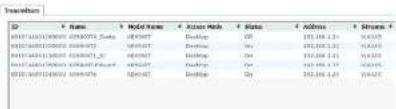
- Once added, the Transmitter appears on the Transmitters main page and Sidebar menu:

Configuring a Transmitter
A Transmitter's settings can be modified from the Transmitters main page. Changes that are saved are updated on the Transmitter device across the network. To configure a Transmitter:
- Select a Transmitter and click Modify.
- The Network tab appears with the Transmitter's IP address settings:
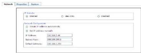
Item Description
IP Installer The IP Installer is an external Windows-based utility for assigning IP addresses to the device. Click one of the radio
| Item Description | |
| Network Configuration | For dynamic IP address assignment, select the Obtain IP address automatically radio button.To specify a fixed IP Address, Subnet Mask, and Default Gateway, select the Set IP address manually radio button and fill in the fields with values appropriate for your network.For information to configure the network settings locally on the device see Network Configuration, page 23. |
- Click the Properties tab to configure the Transmitter's properties:
Network Properties Systems
| Mode ● Interface ○ Desktop | |||||
| PROD. Settings Board Type: 9600 Format: None Data Bits: 8 Bits Stop Bits: 1.5c New Control: None | |||||
| Properties Port GIS: Ven DS Language: English (LS) □ Digital Multisector Audio □ Digital Multisector Audio 8000 Mode Selectator: Hareus □ Digital Media □ Lines: Audio 1400 85232 | |||||
| Manager Address RE Manager ID: 1921382.569 RE Manager Port: 9550 | |||||
| Transmitter Video Address Video Type: Express/DBB Color Depth: 24 bits Network Width Limit: Unlocked | |||||
| Driver RE Enable Copper Timesys [ ] 1600-2400 |
| Item Description | |
| Mode | Select Extender mode for simple one-to-one (Transmitter to User Station) setups that are managed with the Receiver's OSD menu. Select Desktop/Matrix mode to manage devices and connections from the Matrix Manager. This mode is for advanced administration of Transmitter to User Station connections. (See Target Connections, page 74) |
Chapter 7. Device Management
| Item Description | |
| Properties | Port OS: Use the drop-down menu to select the operating system of the computer connected to the Transmitter.OS Language: Use the drop-down menu to select the operating system language of the computer connected to the Transmitter.Enable Multicast Video: Check this box to allow a broadcast of the Transmitter's video signal to be sent to multiple User Stations.Enable Multicast Audio: Check this box to allow a broadcast of the Transmitter's audio signal to be sent to multiple User Stations.EDID Mode Selection: EDID contains a display's basic information and is used by the source device to utilize the best resolution across different monitors. Select how you want the source device to acquire the display's EDID:Default: EDID is set to the default ATEN configuration.Auto: Checks the EDID of all connected displays and uses the best resolution for all displays.Manual: Manually set the EDID configuration from the User Station's OSD (see Manual EDID, page 40).Remix: Checks the EDID of all connected displays and the source device uses the best common resolution for all displays. |
| Enable Media | Select which source type the Transmitter can stream: Video, Audio, USB, and RS232. |
| RS-232 Settings | Configure the serial device settings for the Transmitter. The default settings are:Baud Rate: 9600Parity: NoneData Bits: 8 bitsStop bits: 1 bitFlow Control: None |
| Manager Address | Set the IP address and Port number of the computer running the Matrix Manager software. The default port number is 9110. |
KE6900 / KE6940 User Manual
| Item Description | |
| TransmitterVideo Attributes | These refer to the Transmitter's video settings:Video Type: Select the DVI video connector being used by the display: Digital (DVI-D) or Digital (DVI-I).Color Depth: Select the number of bits to use for the color depth: 24, 16, or 8. This is the number of bits used to describe the color of a single pixel. A bit depth determines the number of colors that can be displayed at one time.Bandwidth Limit: Select the maximum bandwidth that the Transmitter can use to transmit video over the network. A lower bandwidth transmits lower quality video; a higher bandwidth sends higher quality video but this can affect network speed.Video Quality: Select the video quality to use. 5 is the highest video quality, and 1 is the lowest video quality. Options are: 1-5.Background Refresh: Sets how often the Transmitter refreshes the background image on the connected display. Options are to refresh every 256,128, 64, 32,15, or 0 frames. |
| Beeper Check this box for the Transmitter to beep when a configuration change is made. | |
| Occupy Timeout Set a time threshold for User Stations whose Access Mode has been set to Occupy If there is no activity from the User Station occupying the port for the amount of time set here, the User Station is timed out and the port is released. The first User Station to send keyboard or mouse input after the port has been released gets to occupy the port. Input a value from 1 to 240 seconds. | |
- Click the System tab configure the general settings:
Network Properties System
| Description: | ||
| Name: | 02690071_Ganta | Locations: |
| Description: | ||
| IP Address: | 192.158.124 | MAC Address: 30.10.74 wk 01.28 |
| FIS Variables: | 3.5.165 | Solid Number |
| Model Name: | 0269007 | |
Chapter 7. Device Management
| Item Description | |
| General | Enter the Name, Location, and Description of the Transmitter. This section also displays the IP Address, MAC Address, F/W Version, Serial Number, and Model Number. |
| Reboot | Check the box and click Reboot to reset the Transmitter's settings back to the factory default. All custom settings will be lost. |
| Transmitter Password Change | Check Enable to require a password to access to the Transmitter's OSD configuration screens (see page 27).Enter the Old Password, enter a New Password, and confirm the new password in the Confirm Password box. |
- After entering the information, click Save.
Deleting a Transmitter
To delete a Transmitter:
-
Select the Transmitter you want to delete.
-
Click Move Out.
The device list updates with the remaining Transmitters. The Transmitter you deleted will appear on the Unmanaged User Stations main page and Sidebar menu.
Target Connections
With Target connections a User Station can connect to multiple Transmitters, individually or simultaneously and stream the Video, Audio, USB, and Serial source from different Transmitters. For example: you can create a Target that connects to four Transmitters to access a different source on each computer, as shown below:
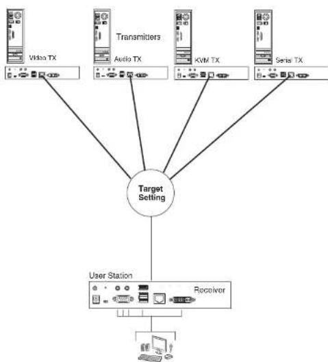
flowchart
graph TD
    A["User Station"] --> B["Receiver"]
    B --> C["Target Setting"]
    C --> D["Video TX"]
    C --> E["Audio TX"]
    C --> F["KWM TX"]
    C --> G["Serial TX"]
Create Targets to allow User Stations to connect to any Transmitters you have setup-individually or simultaneously. The Target defines the connection to the
Targets
A Target defines the Transmitter connections for a User Station. This allows a User Station to connect to different Transmitters and stream sources from different Transmitters, depending on how the Target is defined. Once Targets are created you can select them from the User Station's Connection Page (see Connecting, page 38).
Click Targets from the menu bar and the following screen appears:
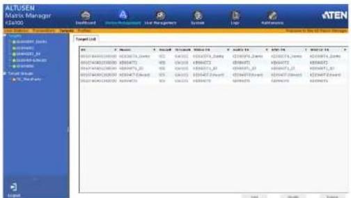
The main page provides an overview of each Target. The Sidebar provides a link with a more detailed view of each.
The meanings of the headings at the top of the page are straightforward.
♦ ID refers to the identification number assigned by the system.
- Name refers to the name entered on the Target's Info page.
- Bound states whether the Target's connections are all bound to the same Transmitter.
- Streams refers to the source type that the Target is configured to stream: Video, Audio, USB, or Serial.
- Video TX, Audio TX, USB TX, RS232 TX lists the Transmitter's name for each source stream.
Adding a Target
To add a Target, do the following:
- From the Targets main page, click Add:

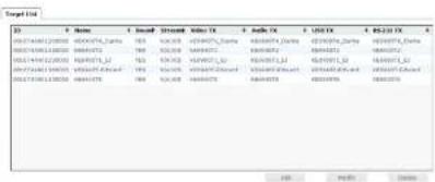
- The Target Info tab appears with the general settings:
Target Info Group Preferences
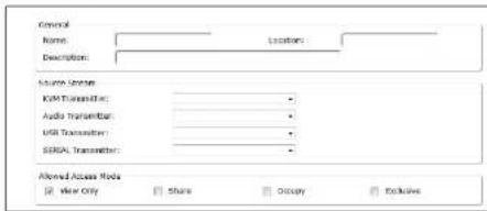
Item Description
General Enter a Name, Location, and Description for the Target.
Source Stream Use the drop-down menu to select the Transmitter to use for each of the Target's source stream: KVM (keyboard/video/mouse), Audio, USB, and Serial.
Chapter 7. Device Management
| Item Description | |
| Allowed Access Mode | Check the box for the type of access mode you want to allow on this Target. This defines how the Target can be accessed when multiple users access it.View Only:Users only have view access to the Target's video display.Share:Users simultaneously share control over the Target.Input from the users is placed in a queue and executed chronologically.Occupy:The first user to access the Target has control over the Target. However, additional users may view the Target's video display. If the user who controls the Target is inactive for longer than the time set in the Timeout box (see Occupy Timeout, page 72), Target control is transferred to the first user to move the mouse or strike the keyboard.Exclusive:The first user to access the Target has exclusive control over the Target. No other users can view the Target. The Timeout function does not apply to Targets which have this setting. |
- Click the Groups tab to add the Target to Target Groups:
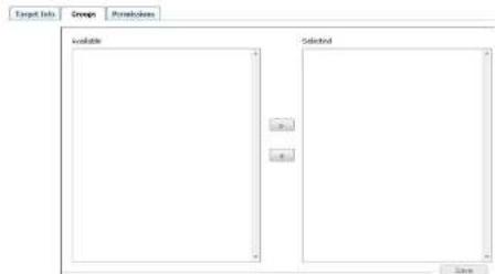
Select a Target Group from the Selected column and use the left arrow to add the Target to the group. Select a Target Group from the Available column and use the right arrow to remove the Target from the group. See Target Groups, page 79 for details.
- Click the Permissions tab to set the Targets access rights:
Target Info Groups Penitiosks
Users/Groups You can assign individual access rights to Users and Groups for the Target by checking the appropriate boxes. View Only: Only has view access to the Target's video display. Share: Can simultaneously share control over the Target. Input from the users is placed in a queue and executed chronologically. Occupy: The first user to access the Target has control over the Target. However, additional users may view the Target's video display. If the user who controls the Target is inactive for longer than the time set in the Timeout box (see Occupy Timeout, page 72), Target control is transferred to the first user to move the mouse or strike the keyboard. Exclusive: The first user to access the Target has exclusive control over the Target. No other users can view the Target: The Timeout function does not apply to Targets which have this setting.
- After entering the information, click Save.
Target Groups
Target Groups allow administrators to easily and efficiently manage users and Targets. Since Target Group access rights apply to any Target that is a member of the group, administrators need only set them once for the group, instead of having to set them for each Target individually. Multiple groups can be defined to allow some users access to specific Targets, while restricting other users from accessing them.
Adding a Target Group
To add a Target Group, do the following:
- Select Target Groups from the Target Sidebar menu, and click Add:
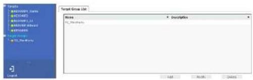
- The Target Group tab appears with the general settings:
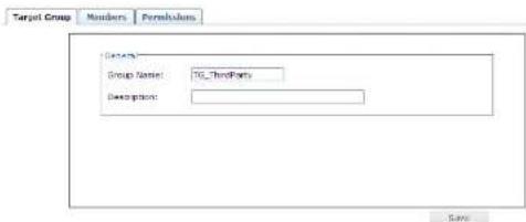
| Item Description | |
| General | Enter a Name and Description for the Target Group. |
- Click the Members tab to add Targets to the group:
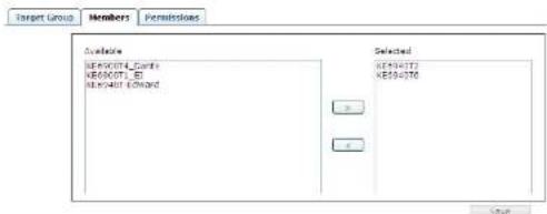
Select a Target from the Selected column and use the left arrow to add it to the group. Select a Target from the Available column and use the right arrow to remove it from the group.
- Click the Permissions tab to set the group access rights:
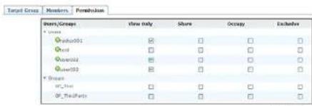
Item Description
Users/Groups You can assign the access rights to Users and Groups for the Target Group by checking the appropriate boxes: View Only: Has view access to the Target video display. Share: Simultaneously share control of the Target. Input from the users is placed in a queue and executed chronologically. Occupy: The first user to access the Target has control over the Target. However, additional users may view the Target's video display. If the user who controls the Target is inactive for longer than the time set in the Timeout box (see Occupy Timeout, page 72), Target control is transferred to the first user to move the mouse or strike the keyboard.
Profiles
Profiles are created for Targets to allow individual User Station access to the connection. Create a Profile for the Target and assign access for each User Station.
Click Profiles from the menu bar and the following screen appears:
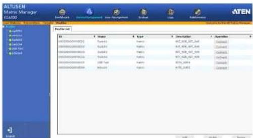
The main page provides an overview of each Profile. The Sidebar provides a link with a more detailed view of each Profile.
The meanings of the headings on the Profile List are straightforward.
♦ ID refers to the identification number assigned by the system.
- Name refers to the name entered on the Profile's Settings page.
• Type refers to the connection type.
- Description refers to the description entered on the Profile's Settings page.
Operation allows you to click Connect to send a Profile's settings to the Transmitters and User Stations.
- Click Modify to change the selected Profile's settings.
- Click Add to create a new Profile.
- Click Delete to remove the selected Profile.
Adding a Profile
To add a Profile, do the following:
- From the Profile main page, click Add:
P2/By Ltd
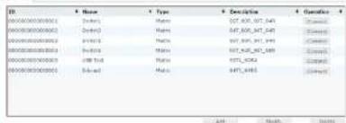
- The Profile Settings tab appears with the Profile and access settings:
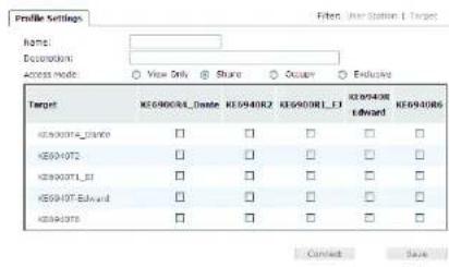
Item Description
Name/Description
Enter a Name and Description for the Target.
Chapter 7. Device Management
| Item Description | |
| Access Mode This | defines how the Target in the Profile can be accessed byUser Stations when multiple users access it.View Only:Users only have view access to the Targets video display.Share:Users simultaneously share control over the Target.Input from the users is placed in a queue and executed chronologically.Occupy:The first user to access the Target has control over the Target. However, additional users may view the Target's video display. If the user who controls the Target is inactive for longer than the time set in the Timeout box (see Occupy Timeout, page 72), Target control is transferred to the first user to move the mouse or strike the keyboard.Exclusive:The first user to access the Target has exclusive control over the Target. No other users can view the Target. The Timeout function does not apply to Targets which have this setting. |
| Target This table | lists all the Targets and User Stations available.Checking a box enables the User Station to use the Target connection, listed to the left. The Target will appear on the User Station's Connection Page (See Connections Page, page 39), allowing you to connect to it. |
| Connect Clicking | Connect will send the Profile settings to theTransmitters and User Stations and will connect the devices accordingly. |
- After entering the information, click Save.
This Page Intentionally Left Blank
Chapter 8
User Management
Overview
User Management has two menu bar items used to create Accounts and Groups. The User Management tab opens on the Accounts page, as shown here:
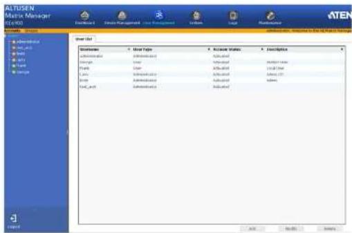
The page is organized into two main areas: the Sidebar at the left, and the large main panel at the right.
- Users and groups appear in the panel at the left of the page. The large panel at the right provides more detailed information at-a-glance for each.
• There are menu bar entries for Accounts (Users) and Groups.
Depending on the menu item selected, either Users or Groups are listed in the Sidebar.
- The sort order of the information displayed can be changed by clicking the main serial column headers.
KE6900 / KE6940 User Manual
Users
The Matrix Manager supports two types of user accounts, shown in the table bellow:
| User Type Role | |
| Administrator Access and | management of the Matrix Manager, including configuration and setting up of devices. Manage Users and Groups. Configure personal working environments. |
| User Access User Stations and connect to Targets they have been given permission for. | |
Adding Users
To add a user, do the following:
-
Select Users in the Sidebar.
-
Click Add at the bottom of the main page. The User tab opens:
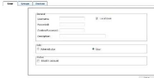
Enter the required information in the fields provided. A description of each is given in the table below:
| Field Description | |
| Username From 1 to | 6 characters are allowed depending on the Account Policy settings. |
| Local User | Check the Local User box if the account is for logging in to |
Chapter 8. User Management
| Field Description | |
| Password From 0 to 16 characters are allowed depending on the Account Policy settings. | |
| Confirm Password To be sure there is no mistake in the password, you are asked to enter it again. The two entries must match. | |
| Description Additional information about the user that you may wish to include. | |
| Role There are two categories: Administrator and User.◆ The Administrators have full access to make changes within the Matrix Manager, which includes adding and removing Transmitters and Receivers, user accounts, preferences, and configuration settings.◆ The Users can log in from User Stations to access Transmitters. | |
| Status Status allows you to control the user's account and access to the installation. as follows:◆ Disable Account lets you suspend a user's account without actually deleting it. so that it can be easily reinstated in the future. |
- At this point you can assign the new user to a group by selecting the Groups tab – the Groups page is discussed on page 91. You can also assign the user's Targets and Groups access rights by selecting the Devices tab – the Devices page is discussed on page 95.
Note: Optionally, you can skip this step now to add more users and create groups, and come back to it later. - When your selections have been made click Save.
- When the Operation Succeeded message appears, click OK.
- Click Users in the Sidebar to return to the main screen. The new user appears in the Sidebar list and in the main panel, as well.
The Sidebar Users list can expand and collapse. If the list is expanded, click the minus symbol (−) next to the Users icon to collapse it; if it is collapsed there is a plus symbol (+) next to the icon. Click the plus symbol to expand it.
• The icon for administrators is orange; the icon for users is green.
KE6900 / KE6940 User Manual
Modifying User Accounts
To modify a user account, do the following:
- In the Sidebar User list, click the user's name
- or -
In the main panel, select the user's name
-
Click Modify
-
In the User page that comes up, make your changes, then click Save.
Note: The User page is discussed on page 86; the Groups page is discussed on page 91, the Devices page is discussed on page 95.
Deleting User Accounts
To delete a user account do the following:
- In the main panel, select the user's name.
- Click Delete.
- Click OK.
Groups
Groups allow administrators to easily and efficiently manage users and devices. Since device access rights apply to anyone who is a member of the group, administrators need only set them once for the group, instead of having to set them for each user individually. Multiple groups can be defined to allow some users access to specific devices, while restricting other users from accessing them.
Creating Groups
To create a group, do the following:
- Select Groups on the menu bar.
- Click Add at the bottom of the main panel. The Group notebook opens, with the Group tab selected:
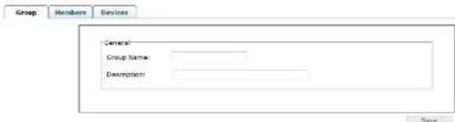
- Enter the required information in the appropriate fields. A description of each of the fields is given in the table below:
| Field Description | h |
| Group Name A maximum of | 16 characters is allowed. |
| Description Additional information about the user that you may wish to include. A maximum of 63 characters is allowed. | |
- At this point you can assign users to the group by selecting the Members tab – the Members page is discussed on page 93. You can also assign the group's Targets and Target Groups access rights by selecting the Devices tab – the Devices page is discussed on page 95.
- When your selections have been made click Save.
KE6900 / KE6940 User Manual
The Sidebar Group list can expand and collapse. If the list is expanded, click the minus symbol (−) next to the Users icon to collapse it; if it is collapsed there is a plus symbol (+) next to the icon. Click the plus symbol to expand it.
- The large main panel shows the group's name, and the description that was given when the group was created
Repeat the above procedure to add additional groups.
Note: You must perform Step 7 before attempting to add a new group, or else the new group you are creating will replace the group you just finished creating.
Modifying Groups
To modify a group, do the following:
- In the Sidebar Group list, click the group's name
- or - In the main panel, select the group's name.
- Click Modify.
- In the Group notebook that comes up, make your changes, then click Save.
Note: The Group page is discussed on page 89; the Members page is discussed on page 93. The Devices page is discussed on page 95.
Deleting Groups
To delete a group do the following:
- In the Sidebar, click the Groups icon.
- In the main panel, select the group's name.
- Click Delete.
- Click OK.
Users and Groups
There are two ways to manage users and groups: from the Users notebook; and from the Group notebook.
Note: Before you can assign users to groups, you must first create them. See Adding Users, page 86 for details.
Assigning Users to a Group From the User's Notebook
To assign a user to a group from the User's notebook, do the following:
- In the Sidebar User list, click the user's name
- or - In the main panel, select the user's name
- Click Modify.
- In the User notebook that comes up, select the Groups tab. A screen, similar to the one below, appears:
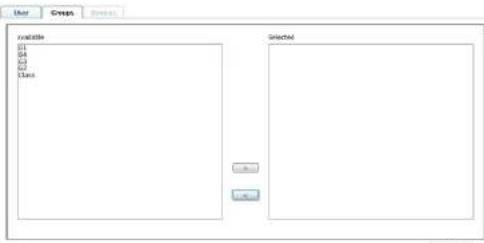
- In the Available column, select the group that you want the user to be in.
- Click the Right Arrow to put the group's name into the Selected column.
- Repeat the above for any other groups that you want the user to be in.
- Click Save when you are done.
Removing Users From a Group From the User's Notebook
To remove a user from a group from the User's notebook, do the following:
- In the Sidebar User list, click the user's name
or
In the main panel, select the user's name.
-
Click Modify
-
In the User notebook that comes up, select the Groups tab. A screen, similar to the one below, appears:
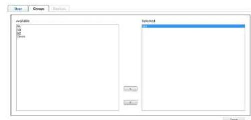
- In the Selected column, select the group that you want to remove the user from.
- Click the Left Arrow to remove the group's name from the Selected column. (It goes back into the Available column.)
- Repeat the above for any other groups that you want to remove the user from.
- Click Save when you are done.
Assigning Users to a Group From the Group's Notebook
To assign a user to a group from the Group notebook, do the following:
- In the Sidebar Group list, click the group's name
or
In the main panel, select the group's name.
-
Click Modify.
-
In the Group notebook that comes up, select the Members tab. A screen, similar to the one below, appears:
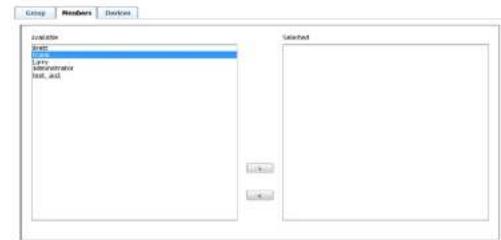
-
In the Available column, select the user that you want to be a member of the group.
-
Click the Right Arrow to put the user's name into the Selected column.
-
Repeat the above for any other users that you want to be members of the group.
-
Click Save when you are done.
Note: If a user has permissions in addition to the ones assigned to the group, the user keeps those permissions in addition to the group ones.
Removing Users From a Group From the Group's Notebook
To remove a user from a group from the Group's notebook, do the following:
- In the Sidebar Group list, click the group's name
or
In the main panel, select the group's name.
-
Click Modify
-
In the Group notebook that comes up, select the Members tab. A screen, similar to the one below, appears:

- In the Selected column, select the user that you want to remove from the group.
- Click the Left Arrow to remove the user's name from the Selected column. (It goes back into the Available column.)
- Repeat the above for any other users that you want to remove from the group.
- Click Save when you are done.
Device
You can assign Target and Target Group permissions from the Devices tab. For information on Targets and Target Groups See Targets, page 75.
Assigning Device Permissions From the User's Notebook
To assign a device permissions to a user from the User's notebook, do the following:
- In the Sidebar User list, click the user's name
or
In the main panel, select the user's name.
- Click Modify.
- In the User notebook that comes up, select the Devices tab. A screen, similar to the one below, appears:
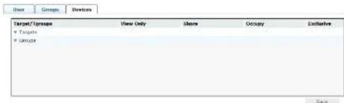
- Make your permission settings for each device according to the information provided below:
| Field Description | |
| Targets Lists the Targets which you can assign access rights to for the user. (See Targets, page 75 for details) | |
| Groups Lists the Target Groups which you can assign access rights to for the user. (See Target Groups, page 79 for details) | |
| Columns Check the boxes to apply access rights on the device for the user. This defines how the Target can be accessed when multiple users access it.View Only:Users can only view the remote screen, and cannot perform operations on it.Share:Users simultaneously share control over the Target.Input from the users is placed in a queue and executed chronologically.Occupy:The first user to access the Target has control over the Target. However, additional users may view the Target's video display. If the user who controls the Target is inactive for longer than the time set in the Timeout box, Target control is transferred to the first user to move the mouse or strike the keyboard.Exclusive:The first user to access the Target has exclusive control over the Target. No other users can view the Target.The Timeout function does not apply to Targets which have this setting. |
- When you have finished making your choices, click Save.
- In the confirmation popup that appears, click OK.
Assigning Device Permissions From the Groups' Notebook
To assign a device permissions to a Group of users, do the following:
- In the Sidebar Groups list, click the group's name or
In the main panel, select the group's name.
- Click Modify.
- In the Groups notebook that comes up, select the Devices tab.
- The screen that comes up is the same one that appears in the User's notebook. The only difference is that whatever settings you make apply to all members of the group instead of just one individual member.
Make your device assignments according to the information described under Assigning Device Permissions From the User's Notebook, page 95.
Chapter 9
System
Overview
The System tab is used to configure the Matrix Manager's system settings and provides three menu bar items: Global Settings, ANMS and Redundancy.
The System tab opens on the Global Settings page, as shown here:
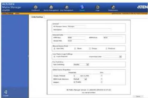
Global Settings
The Global Settings page lets an administrator change the default settings used for the Matrix Manager:
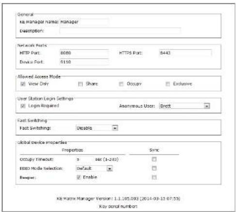
| Item Description | |
| General | Fill in a Name and Description for the Matrix Manager. |
| Network Ports Use this setting to specify the service ports used to access the Matrix Manager:Device Port: This is the port number to configure on the Transmitter and User Station to access the Matrix Manager (see Manager Address, page 34 and Manager Address, page 30). The default is 9110.HTTP Port: This is the port number to use for a browser login. The default is 8080.HTTPS Port: This is the port number to use for a secure | |
KE6900 / KE6940 User Manual
| Item Description | |
| Allowed Access Mode Select the default: Access Mode for devices added to the Matrix Manager. This defines how the device can be accessed when multiple users logon.·View Only: Users can access the computer and view the screen, but cannot perform any operations on it.·Exclusive: The first user to connect to the Transmitter has exclusive control over the computer. No other users can view the computer. The Timeout function does not apply to devices that have this setting.·Occupy: The first user to connect to the Transmitter has control over the computer. However, additional users may view the computers video display. If the user who controls the computer is inactive for longer than the time set in the Timeout box, computer control is transferred to the next user to move the mouse or strike the keyboard.·Share: Users simultaneously share control over the computer. Input from the users is placed in a queue and executed chronologically. | |
| User Station Login Settings | This will be the User Station's default setting when they are added to the Matrix Manager. You can change this setting from the User Station's Properties.·Check Login Required to prompt users for a username and password at the User Station OSD before being able to access the Connections Page (see Connections Page, page 39). If you uncheck this, you must set the Anonymous User.·Anonymous User: If the Login Required box is not checked, select a user from the drop-down menu to use as the default profile to anonymously login to the User Station, in the background.Note: WARNING! If Login Required isn't checked and an Anonymous User isn't selected, a system login error will occur at the User Station OSD. |
| Fast Switching Allows you to select the default resolution to use that gives you the ability to switch faster between User Station and Transmitter connections. | |
Item Description
| Global Device Properties | These settings allow you to set the default properties used by all devices:Occupy Timeout:Set the number of seconds for a user's session to be inactive before the access is released for use by another user, when using the Occupy Access Mode. This will be the default setting for Transmitters.EDID Mode Selection:Extended Display Identification Data (EDID) contains a display's basic information and is used by the source device to utilize the best resolution across different monitors. This will be the default setting for Transmitters. Select how you want the source device to acquire the display's EDID:Default: EDID is set to the ATEN default configuration.Auto: Checks the EDID of all connected displays and uses the best resolution for all displays.Manual: Manually set the EDID configuration from the User Station's OSD (see Manual EDID, page 40).Remix: Checks the EDID of all connected displays and the source device uses the best common resolution for all displays.Beeper: Check this box for the device to alert you with a sound when its first being accessed or when a configuration change is made.Use the Sync check box for each option above to push the setting change to the devices after you click Save. |
KE6900 / KE6940 User Manual
ANMS
The ANMS (Advanced Network Management Settings) page is used to set up login authentication and authorization management from external sources. It is organized as a notebook with two tabs – each with a series of related panels, as described below.
Event Destination
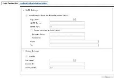
- SMTP Settings
To have the Matrix Manager email reports from the SMTP server to you, do the following:
- Enable the Enable report from the following SMTP Server, select the the Log Level (Information, Warning, or Error), and key in the SMTP Server IP address and SMTP Port.
- If your server requires authentication, check the Server requires authentication checkbox, and key in the appropriate information for the Account Name and Password fields.
Chapter 9. System
Note:
-
Only one email address is allowed in the From field, and it cannot exceed 64 Bytes.
-
| Byte = | English alphanumeric character.
-
Key in the email address (addresses) of where you want the SMTP reports sent to in the To field.
Note: If you are sending the report to more than one email address, separate the addresses with a semicolon. The total cannot exceed 256 Bytes.
- Click Save.
- Syslog Settings
To record all the events that take place on the Matrix Manager and write them to a Syslog server, do the following:
- Check Enable.
- Use the drop-down menu to select the Log Level (Information, Warning, or Error).
- Key in the Server IP address of the Syslog server.
- Key in the Service Port number. The valid port range is 1-65535.
- Click Save.
Authentication & Authorization
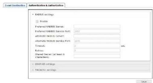
• RADIUS Settings
To allow authentication and authorization for the KE6900 / KE6940 through a RADIUS server, do the following:
- Check Enable.
- Fill in the IP addresses and service port of the Preferred RADIUS Server and Alternate RADIUS Server.
- In the Timeout field, set the time in seconds that the Matrix Manager waits for a RADIUS server reply before it times out.
- In the Retries field, set the number of allowed retries.
- In the Shared Secret field, key in the character string that you want to use for authentication between the Matrix Manager and the RADIUS Server. A minimum of 6 characters is required.
- On the RADIUS server, Users can be authenticated with any of the following methods:
• Set the entry for the user as su/xxxx
Where xxxx represents the Username given to the user when the account was created on the Matrix Manager.
Chapter 9. System
- Use the same Username/Group name on both the RADIUS server and the Matrix Manager.
In each case, the user's access rights are the ones assigned that were assigned when the User of Group was created on the Matrix Manager.
- LDAP / AD Authentication and Authorization Settings:
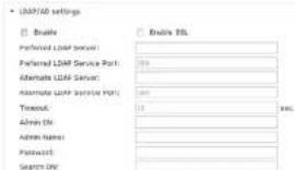
To allow authentication and authorization for the Matrix Manager via LDAP / AD, refer to the information in the table, below:
| Item Action | |
| Enable Put a check in the Enable checkbox to allow LDAP / AD authentication and authorization. | |
| Enable SSL Put a check in the Enable checkbox to allow SSL connections. | |
| LDAP Server IP and Port | Fill in the IP address and port number for the LDAP / AD server.◆ You can use the IPv4 address, the IPv6 address or the domain name in the LDAP Server field.◆ For LDAP, the default port number is 389. |
| Timeout Set the time | in seconds that the Matrix Manager waits for an LDAP / AD server reply before it times out. |
| Admin DN Consult the | LDAP / AD administrator to ascertain the appropriate entry for this field. For example, the entry might look like this: ou-kn4132,dc-aten,dc-com |
| Admin Name Key in the | LDAP administrator's username. |
| Password Key in the | LDAP administrator's password. |
| Search DN Set the | distinguished name of the search base. This is the domain name where the search starts for user names. |
On the LDAP / AD server, Users can be authenticated with any of the
Note: If this method is used, the LDAP schema for MS Active Directory must be extended. Without schema – Only the Usernames used on the Matrix Manager are matched to the names on the LDAP / AD server. User privileges are the same as the ones configured on the Serial Console Server.
- Without schema – Only the Usernames used on the Matrix Manager are matched to the names on the LDAP server. User privileges are the same as the ones configured on the switch.
- Without schema – Only Groups in AD are matched. User privileges are the ones configured for the groups he belongs to on the switch.
- Without schema – Usernames and Groups in AD are matched. User privileges are the ones configured for the User and the Groups on the switch.
• TACACS+ Settings:
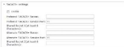
- Enable TACACS+ and enter the following information:
• Preferred TACACS+ Server
• Preferred TACACS+ Service Port
- Shared Secret 1
Alternate TACACS+ Server
• Alternate TACACS+ Service Port
- Shared Secret 2
Chapter 9. System
Redundancy
The Redundancy page sets up a second computer as backup in case the computer hosting the Matrix Manager goes off-line. If the Matrix Manager is off-line, the secondary computer will automatically take over operations, allowing all connections to continue without disruption – with only a brief period (30 seconds) when new connections can't be started. When the primary computer comes back online it retrieves the database with any changes from the secondary computer and re-takes all Matrix Manager operations.
To setup Redundancy, do the following:
- Install the Matrix Manager on a second computer with the USB License key (see page 43).
- Open the Matrix Manager and go to the System → Redundancy page.
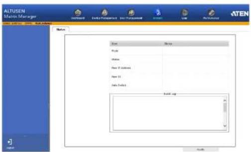
- Click Modify. The Status window appears:
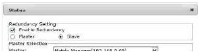
KE6900 / KE6940 User Manual
- Use the Master drop-down menu to select the primary computer's IP address.
- Click OK.
- This computer is now running in Standby mode, as identified in the orange status bar:

- Remove the USB License key and plug it into the primary computer running the Matrix Manager software.
- Open the Matrix Manager on the primary computer and go to the System > Redundancy page.
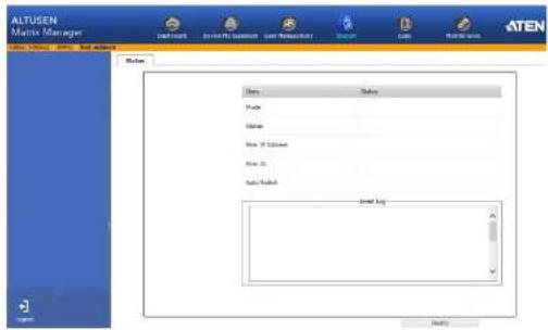
- Click Modify. The Status window appears:
Chapter 9. System
- Check the Enable Redundancy box and select the Master radio button.
- Use the Slave drop-down menu to select the secondary computer's IP address.
- Enter the Username and Password of the secondary computer's local administrator account.
- Check the Auto Switch box to automatically switch the Matrix Manager to the secondary computer when the primary computer is offline – and reverse the action when the primary computer is back online.
- Click OK.
- The Redundancy page provides information about the configuration.
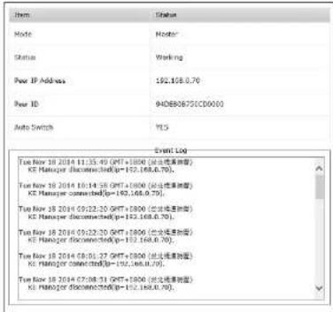
Item Action
Mode Displays the role of the computer running the Matrix Manager software: Master (primary) or Slave (secondary).
Status Displays Working for the computer currently managing the Matrix Manager database. Displays Standby when the computer is waiting as a backup and getting database updates from the primary computer running the Matrix Manager
KE6900 / KE6940 User Manual
| Item Action | |
| Peer ID Displays the | MAC address of the computer configured to send (primary) or receive (secondary) the database updates for redundancy. |
| Auto Switch Displays the Auto Switch (Yes/No) status. (Master only). | |
| Event Log Displays the logs that provide information about the Matrix Manager's redundancy status. | |
Chapter 10
Logs
Overview
The Matrix Manager logs all the events that take place on it an stores them in a Log. The Logs tab opens on the System Log page, as shown here:
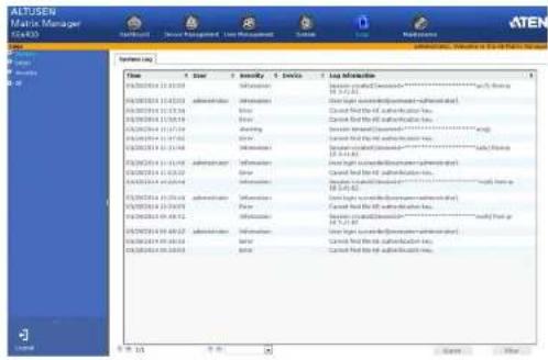
System Log
The System Log page displays events that take place on the Matrix Manager and provides a breakdown of the time, user, severity, device, and log information, for a description of each event. You can change the sort order of the display by clicking on the column headings.
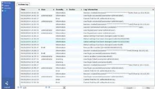
- The first four buttons on the lower row navigate through the pages of the listed events. The left takes you to the first page; the right takes you to the last page; the middle buttons move you backward or forward one page.
Note: These buttons are only active when there is a relevant action they can perform. For example, when there is more than one page of information and you are on the first page, the "move forward" and "last page" buttons are active, but the "move backward" and "first page" buttons are not.
- Clicking the plus sign (+) beside a category in the sidebar menu expands the event headings into subcategories. Selecting a subcategory allows you to view only the logs that relate to that choice.
- Clicking All from the sidebar returns you to the default view to display all events.
In general, a blank page, indicates that there were no long words presented for that category.
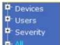
Chapter 10. Logs
The log file tracks a maximum of 512 events. When the limit is reached, the oldest events get discarded as new events come in. The buttons at the bottom of the page are shown below and described in the table:
| 1/2 | Export | Filter |
| Button Explanation | |
| Navigation Buttons The four | buttons on the lower row (right side) navigate through the pages of the listed events. The left takes you to the first page: the right takes you to the last page: the middle buttons move you backward or forward one page. |
| Drop-Down Menu Use this menu to select how many events you want to display per page. Available choices are 25, 50, and 100. | |
| Export | Clicking Export lets you save the contents of the log to a file on your computer. |
| Filter | Clicking Filter allows you to search for particular events by date or by specific words or strings, as described in the next section. |
Filter
Filter lets you narrow the log event display to ones that occurred at specific times; ones containing specific words or strings. When you access this function, the log filter dialog box appears at the bottom of the page:
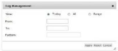
KE6900 / KE6940 User Manual
(Continued from previous page.)
A description of the filter items is given in the table, below:
| Item Description |
| Time This feature lets you filter for events that occurred at specific times, as follows: Today: Only the events for the current day are displayed. All: Displays all events. Range: Select a time frame of events. Alter selecting Range, click inside the From/To text box in order to bring up the calendar. • From: Filters for events from a specific date and time to the present. Put a check in the checkbox to bring up a calendar. Set the date and time that you want the filtering to start from. All events from the Start date/time to the present are displayed. • To: Filters for events from a specific date and time to a specific date and time. First select the From (described above). After checking Range, you have to click inside the text box in order to bring up the calendar. |
| Pattern Filters for a particular word or string. Key the word or string into the information text box. Only events containing that word or string are displayed. Wildcards (? for single characters; *for multiple characters) and the keyword or are supported. E.g., h'ds would return hands and hoods; h?nd would return hand and hind, but not hard; h'ds or h*ks would return hands and hooks. |
| Apply Click to apply the filter choices. |
| Reset Click this button to clear the entries in the dialog box and start with a clean slate. |
| Cancel Click this button to exit the log filter function. |
Chapter 11 Maintenance
Overview
The Maintenance tab has four menu bar options: Backup/Restore, Firmware Upgrade, Certificates, and Preferences. When you click the Maintenance tab, it opens on the Backup/Restore page, as shown here:
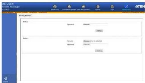
- Backup/Restore allows administrators to backup system configuration settings to a file, and restore configuration settings from previously saved files.
- Firmware Upgrade allows administrators to upgrade firmware for network connected devices.
- Certificates allow for enhanced security, the Private Certificate section allows you to use your own private encryption key and signed certificate.
- Preferences allows the user that is logged in to set individual preferences for their browser sessions.
Backup / Restore
When you click the Maintenance tab Matrix Manager, the Backup/Restore page is displayed. The page is divided into two main sections: Backup, and Restore:
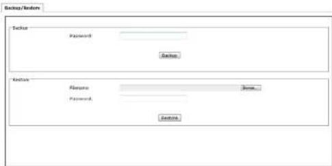
The operations to perform backup/restore procedures are described in the table below:
| Procedure Operation |
| Backup Backs Up the Matrix Manager configuration – including User Station, Transmitter, Target, and Profile configurations; user and group accounts, user profiles, logs, and system settings. |
| Restore Deletes the current User Station, Transmitter, Target, and Profile configurations; user and group accounts, user profiles, logs, and system settings; then restores those settings to the values that exist in the previously saved backup file. |
Backup
To back up system configuration settings, do the following:
- (Optional) In the Backup panel, provide a password for the backup file. Any combination of characters may be used for the password.
Note: Providing a password is a security feature – if you provide a password, you will need to give the same password in order to
- In the dialog box that comes up, Click Save to save the configuration file (System.conf) to a location on your hard disk.
- Navigate to the directory where you want to save the file and click Save.
Restore
To restore system configuration settings, do the following:
- In the Restore panel, click Browse.
- Navigate to the directory where the backup file is located and select it.
- When you return to the Backup/Restore page enter the password you set when the backup file was created.
Note: If you did not set a password for the file, leave the field blank.
-
Click Restore.
-
Click OK to confirm that you want to restore the configuration data. When the Restore procedure is in process, a message stating that the Matrix Manager will restart will appear. After a short while the Matrix Manager closes and refreshes at the log in screen. When it comes back up the configuration settings that were restored from the backup file are in effect.
Firmware Upgrade
New firmware versions can be downloaded from our website as they become available. Check the website regularly, to find the latest upgrade packages.
Under Firmware Upgrade all KE6900/KE6940 devices that are discovered online are provided in a list allowing you to select which devices get upgraded.
To upgrade the firmware do the following:
- Go to our website and download the firmware upgrade package appropriate to your KE6900 / KE6940 device.
- Open your browser and log in to the Matrix Manager with an administrator's account.
- Click the Maintenance tab; select Firmware Upgrade on the menu bar. A confirmation dialog box may appear:
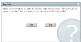
- Click Yes to continue. After a short while, the Firmware Upgrade page comes up:
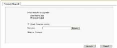
All the KE6900 / KE6940 devices that are capable of being upgraded are
- Make sure there is a check in the checkbox in front of the modules you want to upgrade. Uncheck the modules that you do not want to upgrade.
- Click Browse. Navigate to the directory where the firmware upgrade file is located and select it.
- Enable or disable Check Firmware Version
- If you enabled Check Firmware Version the current firmware level is compared with that of the upgrade file. If the current version is equal to or higher than the upgrade version, a popup message appears, to inform you of the situation and stops the upgrade procedure.
If you didn't enable Check Main Firmware Version, the upgrade file is installed without checking what its level is.
- Click Upgrade to start the upgrade procedure. As the upgrade proceeds, progress information is shown on the screen. Once the upgrade completes successfully, the devices will reset.
- Log in to the and check the firmware version to be sure it is the new one.
Firmware Upgrade Recovery
If the Upgrade Succeeded screen doesn't appear or the upgrade procedure is abnormally halted (due to computer crash, power failure, etc.), the device may become inoperable. If you find that the device does not work following a failed or interrupted upgrade, do the following
- Power off the KE6900 / KE6940.
- Press the Reset button, then power on the KE6900 / KE6940 while holding Reset.
- Hold Reset for 5 seconds after the device is powered on.
- The device will revert to a previous firmware version and recover from the failure.
- Upgrade the firmware to the most current version available.
Certificates
This page provides information about the Private Certificates:
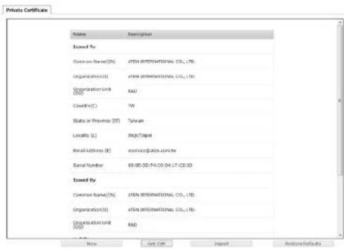
Private Certificate
When logging in over a secure (SSL) connection, a signed certificate is used to verify that the user is logging in to the intended site. For enhanced security, the Private Certificate section allows you to use your own private encryption key and signed certificate, rather than the default ATEN certificate.
There are two methods for establishing your private certificate: generating a self-signed certificate; and importing a third-party certificate authority (CA) signed certificate.
• Generating a Self-Signed Certificate
If you wish to create your own self-signed certificate, a free utility – openssl.exe – is available for download over the web. See Self-Signed Private Certificates, page 139 for details about using OpenSSL to generate your own private key and SSL certificate.
After the CA sends you the certificate and private encryption key, save them to a convenient location on your computer.
- Importing the Private Certificate
To import the private certificate, do the following:
- Click Import from the bottom of the Private Certificate page, shown here:
| New | Get CSR | Import | Restore Defaults |
-
Click Browse to the right of Certificate Filename; and browse to where your certificate file is located; and select it.
-
Click Import to complete the procedure.
Note: Clicking Restore Defaults returns the device to using the default ATEN certificate.
Certificate Signing Request
The Certificate Signing Request (CSR) section provides an automated way of obtaining and installing a CA signed SSL server certificate.
| New | Get CSR | Import | Restore Defaults |
To perform this operation do the following:
- Click New. The following dialog box appears:
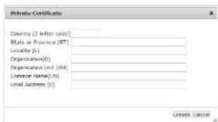
- Fill in the form – with entries that are valid for your site – according to the example information in the following table:
KE6900 / KE6940 User Manual
| Information Example | |
| State or Province Taiwan | |
| Locality Taipei | |
| Organization Your Company, Ltd. | |
| Organization Unit Tech Department | |
| Common Name mycompany.com | |
| Note: This must be the exact domain name of the site that you want the certificate to be valid for. If the site's domain name is www.mycompany.com, and you only specify mycompany.com, the certificate will not be valid. | |
| Email Address administrator@yourcompany.com | |
-
After filling in the form (all fields are required), click Create. A self-signed certificate based on the information you just provided is now stored on the Matrix Manager.
-
Click Get CSR, and save the certificate file (csccer) to a convenient location on your computer. This is the file that you give to the third party CA to apply for their signed SSL certificate.
-
After the CA sends you the certificate, save it to a convenient location on your computer. Click Import to locate the file; then click Import to store it on the Matrix Manager.
Note: When you upload the file, the Matrix Manager checks the file to make sure the specified information still matches. If it does, the file is accepted; if not, it is rejected.
If you want to remove the certificate (to replace it with a new one because of a domain name change, for example), simply click Restore Defaults.
Preferences
Users can set individual preferences for their browser sessions on the Preferences page. The Preferences page allows you to select options for the user that is currently logged in.
| Language: | English | |
| Toolbar Hotkey: | [Ctrl][Ctrl] | |
| Logout Timeout: | 30 min (0-180) | Disabled |
| Screen Blanker: | 0 min (0-30) | Disabled |
| Welcome Message: | Enable | Username |
| Old Password: | ********** | |
| New Password: | ********** | |
| Confirm Password: | ********** | |
| Item Description |
| Language Click the drop-down menu to select the language you want to use during sessions for this user. Choices are: English, Chinese (Simplified), Chinese (Traditional), Japanese, Korean, Dutch, French, Spanish, Portuguese, and Russian. |
| Toolbar Hotkey Select the hotkey combination to call the Tool Bar function for this user. The Tool Bar is used when accessing the computer from the Transmitter or Receiver side. |
| Logout Timeout If there is no user input for the amount of time set with this function, the user is automatically logged out. A login is necessary before the Matrix Manager can be accessed again. The default is 30 minutes. |
| Screen Blanker Set how many minutes the KE6900 / KE6940 waits when a session is idle before turning off the display. |
| Welcome Page If you want the Welcome Message to appear on screen when the user logs in, select Enable.If you want the user's Screen Name to appear with the Welcome Message, check the Username check box. |
KE6900 / KE6940 User Manual
| Item Description | |
| Password This section allows you to change the user's password: | |
| 1. Key in your old password in the Old password field.2. Key in your new password in the New password field.3. Key in your new password again in the Confirm password field. | |
When you have made your choices, Click Save.
To use the original system set preferences, click Restore Defaults.
Chapter 12
Firmware Upgrade Utility
The Windows-based Firmware Upgrade Utility (FWUpgrade.exe) provides a smooth, automated process for upgrading the KVM switch's firmware. The Utility comes as part of a Firmware Upgrade Package that is specific for each device. New firmware upgrade packages are posted on our web site as new firmware revisions become available. Check the web site regularly to find the latest packages and information relating to them:
http://www.aten.com
Preparation
- From a computer that is not part of your KVM installation go to our Internet support site and choose the model name that relates to your device KE6900 / KE6940 to get a list of available Firmware Upgrade Packages.
- Choose the Firmware Upgrade Package you want to install (usually the most recent), and download it to your computer.
- Be sure that the computer is connected to the same LAN segment as the KE6900 / KE6940 devices.
KE6900 / KE6940 User Manual
Starting the Upgrade
To upgrade your firmware:
- Run the downloaded Firmware Upgrade Package file - either by double clicking the file icon, or by opening a command line and entering the full path to it. The Firmware Upgrade Utility Welcome screen appears:
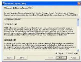
Note: The screens shown in this section are for reference only.
- Read the License Agreement (enable the I Agree radio button).
- Click Next. The Firmware Upgrade Utility main screen appears:
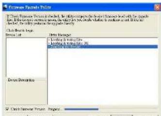
-
The Firmware Upgrade Utility
-
The Utility inspects your installation. All the devices capable of being upgraded by the package are listed in the Select Master Device list.
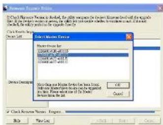
- After you have made your device selection, Click OK and then Next to begin the upgrade.
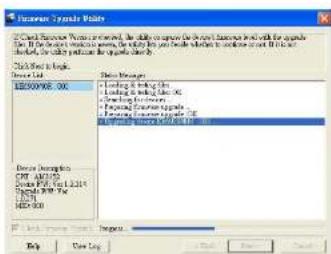
If you enabled Check Firmware Version, the Utility compares the device's firmware level with that of the upgrade files. If it finds that the device's version is higher than the upgrade version, it brings up a dialog box informing you of the situation and gives you the option to Continue or Cancel.
If you didn't enable Check Firmware Version, the Utility installs the
KE6900 / KE6940 User Manual
Upgrade Succeeded
After the upgrade has completed, a screen appears to inform you that the procedure was successful:
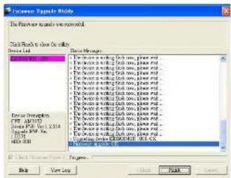
- The Firmware Upgrade Utility
Firmware Upgrade Recovery
If the Upgrade Succeeded screen doesn't appear or the upgrade procedure is abnormally halted (due to computer crash, power failure, etc.), the device may become inoperable. If you find that the device does not work following a failed or interrupted upgrade, do the following
- Power off the KE6900 / KE6940.
- Press the Reset button, then power on the KE6900 / KE6940 while holding Reset.
- Hold Reset for 5 seconds after the device is powered on.
- The device will revert to a previous firmware version and recover from the failure.
- Upgrade the firmware to the most current version available.
This Page Intentionally Left Blank
Appendix
Safety Instructions
General
- This product is for indoor use only.
- Read all of these instructions. Save them for future reference.
♦ Follow all warnings and instructions marked on the device.
Do not place the device on any unstable surface (cart, stand, table, etc.). If the device falls, serious damage will result.
♦ Do not use the device near water. - Do not place the device near, or over, radiators or heat registers.
The device cabinet is provided with slots and openings to allow for adequate ventilation. To ensure reliable operation, and to protect against overheating, these openings must never be blocked or covered.
The device should never be placed on a soft surface (bed, sofa, rug, etc.) as this will block its ventilation openings. Likewise, the device should not be placed in a built-in enclosure unless adequate ventilation has been provided. - Never spill liquid of any kind on the device.
- Unplug the device from the wall outlet before cleaning. Do not use liquid or aerosol cleaners. Use a damp cloth for cleaning.
- The device should be operated from the type of power source indicated on the marking label. If you are not sure of the type of power available, consult your dealer or local power company.
- The device is designed for IT power distribution systems with 230V phase-to-phase voltage.
- To prevent damage to your installation it is important that all devices are properly grounded.
- The device is equipped with a 3-wire grounding type plug. This is a safety feature. If you are unable to insert the plug into the outlet, contact your electrician to replace your obsolete outlet. Do not attempt to defeat the purpose of the grounding-type plug. Always follow your local/national
If an extension cord is used with this device make sure that the total of the ampere ratings of all products used on this cord does not exceed the extension cord ampere rating. Make sure that the total of all products plugged into the wall outlet does not exceed 15 amperes.
- To help protect your system from sudden, transient increases and decreases in electrical power, use a surge suppressor, line conditioner, or uninterruptible power supply (UPS).
- Position system cables and power cables carefully: Be sure that nothing rests on any cables.
- Never push objects of any kind into or through cabinet slots. They may touch dangerous voltage points or short out parts resulting in a risk of fire or electrical shock.
- Do not attempt to service the device yourself. Refer all servicing to qualified service personnel.
- If the following conditions occur, unplug the device from the wall outlet and bring it to qualified service personnel for repair.
• The power cord or plug has become damaged or frayed.
♦ Liquid has been spilled into the device.
- The device has been exposed to rain or water.
- The device has been dropped, or the cabinet has been damaged.
- The device exhibits a distinct change in performance, indicating a need for service.
- The device does not operate normally when the operating instructions are followed.
- Only adjust those controls that are covered in the operating instructions. Improper adjustment of other controls may result in damage that will require extensive work by a qualified technician to repair.
- Do not connect the RJ-11 connector marked "UPGRADE" to a public telecommunication network.
Appendix
Rack Mounting
- Before working on the rack, make sure that the stabilizers are secured to the rack, extended to the floor, and that the full weight of the rack rests on the floor. Install front and side stabilizers on a single rack or front stabilizers for joined multiple racks before working on the rack.
- Always load the rack from the bottom up, and load the heaviest item in the rack first.
Make sure that the rack is level and stable before extending a device from the rack.
Use caution when pressing the device rail release latches and sliding a device into or out of a rack; the slide rails can pinch your fingers. - After a device is inserted into the rack, carefully extend the rail into a locking position, and then slide the device into the rack.
- Do not overload the AC supply branch circuit that provides power to the rack. The total rack load should not exceed 80 percent of the branch circuit rating.
- Make sure that all equipment used on the rack – including power strips and other electrical connectors – is properly grounded.
- Ensure that proper airflow is provided to devices in the rack.
- Ensure that the operating ambient temperature of the rack environment does not exceed the maximum ambient temperature specified for the equipment by the manufacturer.
- Do not step on or stand on any device when servicing other devices in a rack.
Technical Support
International
- For online technical support – including troubleshooting, documentation, and software updates: http://support.aten.com
• For telephone support. See Telephone Support, page iii:
North America
| Email Support support@aten-usa.com | ||
| Online Technical Support | Troubleshooting Documentation Software Updates | http://www.aten-usa.com/support |
| Telephone Support 1-888-999-ATEN ext 4988 | ||
When you contact us, please have the following information ready beforehand:
Product model number, serial number, and date of purchase.
- Your computer configuration, including operating system, revision level, expansion cards, and software.
• Any error messages displayed at the time the error occurred.
• The sequence of operations that led up to the error.
• Any other information you feel may be of help.
Appendix
Specifications
| Function KE6900T KE6940T | |||
| Connectors Console Ports | Keyboard 1 x USB Type A Female (White) | ||
| Video 1 x DV-1 Female(White) | 2 x DVI-I Female(White) | ||
| Mouse 1 x USB Type A Female (White) | |||
| Speaker 1 x Mini Stereo Jack Female (Green) | |||
| Mic. 1 x Mini Sterec Jack Female (Pink) | |||
| RS-232 1 x DB-9 Male (Black) | |||
| KVM Ports | KB / Mouse USB Type B Female (White) | ||
| Speaker 1 x Mini Stereo Jack (Green) | |||
| Mic. 1 x Mini Sterec Jack (Pink) | |||
| Video 1 x DV-1 Female(White) | 2 x DVI-I Female(White) | ||
| RS-232 1 x DB-9 Female (Black) | |||
| Power 1 x DC Jack (Black) | |||
| LAN | 1 x RJ-45 Female (Black) | ||
| Switches | Console Selection / Config | 1 x Slide switch (Black)(Auto, Local, Config) | |
| Reset | 1 x Semi-recessed Pushbutton | ||
| LEDs LAN | 1 (Green / Orange) | ||
| Power | 1 x Blue | ||
| Local | 1 x Green | ||
| Remote | 1 x Green | ||
| Emulation | Keyboard / Mouse | USB | |
| Power Consumption | DC 5V | DC 5V | |
| Video | Up to 1920 x 1200 | ||
| Environment | Operating Temp. | 0-50°C | |
| Storage Temp | -20-60°C | ||
| Humidity | 0-95% RH, Non-condensing | ||
KE6900 / KE6940 User Manual
| Function KE6900R KE6940R | |||
| Connectors USB Virtual Media 2 x USB Type A Female (White) | |||
| Console Ports | Keyboard 1 x USB Type A Female (White) | ||
| Video 1 x DVI-I Female(White) | 2 x DVI-I Female(White) | ||
| Mouse 1 x USB Type A Female (White) | |||
| Speaker 1 x Mini Stereo Jack Female (Green) | |||
| Mic. 1 x Mini Stereo Jack Female (Pink) | |||
| RS-232 1 x DB-9 Male (Black) | |||
| Power 1 x DC Jack (Black) | |||
| LAN 1 x RJ 45 Female (Black) | |||
| Switches OSD | 1 x Pushbutton | ||
| Video 1 x Pushbutton | |||
| Graphics | 1 x Pushbutton | ||
| Console Selection / Config | 1 x Slide switch (Black)(Auto, Config) | ||
| Reset | 1 x Semi-recessed Pushbutton | ||
| LEDs LAN | 1 (Green / Orange) | ||
| Power | 1 x Blue | ||
| Local | 1 x Green | ||
| Remote | 1 x Green | ||
| Emulation | Keyboard / Mouse | USB | |
| Power Consumption | DC 5V | DC 5V | |
| Video | Up to 1920 x 1200 | ||
| Environment | Operating Temp. | 0–50°C | |
| Storage Temp | -20–60°C | ||
| Humidity | 0–95% RH, Non-condensing | ||
| Physical Properties | Housing | Metal | |
| Weight | 1.25 kg | 1.25 kg | |
| Dimensions | 22.80 x 17.10 x 55.00 cm | ||
Appendix
IP Installer
From a client computer running Windows, an IP address for a transmitter or receiver can be assigned with the IP Installer utility. The utility can be obtained from the Download area of our website. Look under Driver/SW. After downloading the utility to your client computer, do the following:
- Unzip the contents of IPInstaller.zip to a directory on your hard drive.
- Go to the directory that you unzipped the IPInstaller program to and run IPInstaller.exe. A dialog box similar to the one below appears:
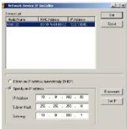
- Select the Transmitter or Receiver in the Device List.
Note: 1. If the list is empty, or your device doesn't appear, click Enumerate to refresh the Device List.
-
If there is more than one device in the list, use the MAC address to pick the one you want. The MAC address is located on the devices bottom panel.
-
Select either Obtain an IP address automatically (DHCP), or Specify an IP address. If you chose the latter, fill the IP Address, Subnet Mask, and Gateway fields with the information appropriate to your network.
- Click Set IP.
Trusted Certificates
Overview
When you try to log in to the device from your browser, a Security Alert message appears to inform you that the device's certificate is not trusted, and asks if you want to proceed.
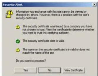
The certificate can be trusted, but the alert is triggered because the certificate's name is not found on the Microsoft list of Trusted Authorities. You can ignore the warning and click Yes to go on.
Appendix
Self-Signed Private Certificates
If you wish to create your own self-signed encryption key and certificate, a free utility - openssl.exe - is available for download over the web at www.openssl.org. To create your private key and certificate do the following:
-
Go to the directory where you downloaded and extracted openssl.exe to.
-
Run openssl.exe with the following parameters:
openssl req -now -newkey rsa:1024 -days 3653 -nodes -x509 keyout CA.key out CA.cer config openssl.cnf
Note: 1. The command should be entered all on one line (i.e., do not press [Enter] until all the parameters have been keyed in).
- If there are spaces in the input, surround the entry in quotes (e.g., "ATEN International").
To avoid having to input information during key generation the following additional parameters can be used:
/C /ST /L /O /OU /CN /emailAddress.
Examples
openssl req -now -nowkey rsa:1024 -days 3653 -nodes -x509 keyout CA.key out CA.per config openssl.cnf subj /C-yourcountry/ST-yourstateorprovince/I-yourlocationor city/O=yourorganization/OU=yourorganizationalunit/ CN-yourcommonname/emailAddress-name@yourcompany.com
openssl req-new-newkey rsa:1024-days 3653-nodes-x509-keyout CA.key-out CA.cer-config openssl.cnf-subj/C-CA/ST-BC/L-Richmond/O-"ATEN International"/OU-ATEN/CN-ATEN/emailAddress-eservice@aten.com.tw
Importing the Files
After the openssl.exe program completes, two files - CA.key (the private key) and CA.cer (the self-signed SSL certificate) - are created in the directory that you ran the program from
Limited Warranty
ALTUSEN warrants this product against defects in material or workmanship for a period of one (1) year from the date of purchase. If this product proves to be defective, contact ALTUSEN's support department for repair or replacement of your unit, ALTUSEN will not issue a refund. Return requests can not be processed without the original parcel of purchase.
When returning the product, you must ship the product in its original packaging or packaging that gives an equal degree of protection. Include your proof of purchase in the packaging and the RMA number clearly marked on the outside of the package.
This warranty becomes invalid if the factory-supplied serial number has been removed or altered on the product.
This warranty does not cover cosmetic damage or damage due to acts of God, accident, misuse, abuse, negligence or modification of any part of the product. This warranty does not cover damage due to improper operation or maintenance, connection to improper equipment, or attempted repair by anyone other than ALTUSEN. This warranty does not cover products sold AS IS or WITH FAULTS.
IN NO EVENT SHALL ALTUSEN'S LIABILITY EXCEED THE PRICE PAID FOR THE PRODUCT. FURTHER, ALTUSEN SHALL NOT BE RESPONSIBLE FOR DIRECT, INDIRECT, SPECIAL, INCIDENTAL OR CONSEQUENTIAL DAMAGES RESULTING FROM THE USE OF THE PRODUCT. ITS ACCOMPANYING SOFTWARE, OR ITS DOCUMENTATION. ALTUSEN SHALL NOT IN ANY WAY BE RESPONSIBLE FOR WITHOUT LIMITATION, LOSS OF DATA, LOSS OF PROFITS, DOWNTIME, GOODWILL. DAMAGE OR REPLACEMENT OF EQUIPMENT OR PROPERTY, AND ANY EXPENSES FROM RECOVERY, PROGRAMMING, AND REPRODUCTION OF ANY PROGRAM OR DATA.
ALTUSEN makes no warranty or representation, expressed, implied, or statutory with respect to its products, content or use of this documentation and all accompanying software, and specifically disclaims its quality, performance, merchantability, or fitness for any particular purpose.
ALTUSEN reserves the right to revise or update its product, software or documentation without obligation to notify any individual or entity of such revisions, or update.
For details about extended warranties, please contact one of our dedicated value added resellers.
Index
A
Adding a New Device, 59 Adding Users, 86
B
Components, 5 Configuring a Device, 69 Control Center Screen Components, 50 User Interface, 27 Creating Groups, 89
D
Deleting a Device, 63, 73 Deleting groups, 90 Deleting user accounts, 88 Device Permissions assigning, 95, 97
F
Filter, 113 Firmware upgrading, 115 Firmware Upgrade, 125 Firmware upgrade recover
G
Groups assigning users, 91, 93 creating, 89
removing users, 92, 94
L
Log, 111 filter, 113
M
Maintenance, 115 Managing Groups, 89 Managing Users, 86 Modifying groups, 90 Modifying user accounts, 88
0
Online Registration, iii
P
Password System administrator, 38, 49 Port Access filter log, 113 Preferences, 123 Private Certificates, 139
R
Rack mounting, 13, 15 Requirements Operating Systems, 4 OS Support, 4 RoHS, ii
S
SJ/T 11364-2006, ii
Specifications, 135
System administrator password, 38, 49
System Requirements Computers, 3
T
Tab bar, 52
Technical Support, 134
Telephone support, iii
Tree View, 51
Trusted Certificates, 138
U
Upgrade firmware, 115
User Interface, 27
Tab bar. 52
User Management, 85
User Notice, iii
User Preferences, 123
Users
Adding, 86
assigning to groups, 91, 93
Deleting, 88
Managing, 86
Modifying, 88
removing from groups, 92, 94
Users and Groups, 91
- FCC, CE Information
- RoHS
- Telephone Support
- User Notice
- Package Contents
- Basic Package
- Contents
- Chapter 1.
- Introduction
- Chapter 2.
- Hardware Setup
- Chapter 3.
- OSD Operation
- Chapter 4.
- Matrix Manager Installation
- Chapter 5.
- Browser Operation
- Chapter 6.
- Dashboard
- Chapter 7.
- Device Management
- Chapter 8.
- User Management
- Chapter 10.
- Logs
- Chapter 11.
- Maintenance
- Chapter 12.
- Firmware Upgrade Utility
- Appendix
- About This Manual
- Conventions
- Product Information
- Chapter 1 Introduction
- Overview
- Features
- Requirements
- Console
- Computers
- Cables
- Software
- Operating Systems
- Components
- Chapter 2 Hardware Setup
- Rack Mounting
- Wall Mounting
- Setting Up a Point-to-Point Installation
- Setting Up a LAN Installation
- KE6900 / KE6940 User Manual
- Network Configuration
- Return
- Default IP Addresses
- Chapter 3
- LED Display
- Invoking the OSD
- OSD Interface
- User Station Configuration
- Network
- Properties
- System
- Transmitter Configuration
- User Preferences
- Connecting
- Connections Page
- Profile Page
- Chapter 4
- Download
- Matrix Manager Install
- Chapter 5
- Logging In
- The Matrix Manager Main Page
- Web Components
- Tree View Considerations
- The Tab Bar
- Icon Function
- Chapter 6 Dashboard
- Active Connections
- Active Sessions
- Online User Stations
- Online Transmitters
- Latest Events
- Chapter 7
- Adding a User Station
- Configuring a User Station
- Item Description
- Deleting a User Station
- Rx Video Group
- Adding an Rx Video Group
- Transmitters
- Adding a Transmitter
- Configuring a Transmitter
- Deleting a Transmitter
- Target Connections
- Targets
- Adding a Target
- Target Groups
- Adding a Target Group
- Profiles
- Adding a Profile
- Chapter 8
- Users
- Adding Users
- Modifying User Accounts
- Deleting User Accounts
- Groups
- Creating Groups
- Modifying Groups
- Deleting Groups
- Users and Groups
- Assigning Users to a Group From the User's Notebook
- Removing Users From a Group From the User's Notebook
- Assigning Users to a Group From the Group's Notebook
- Removing Users From a Group From the Group's Notebook
- Device
- Assigning Device Permissions From the User's Notebook
- Assigning Device Permissions From the Groups' Notebook
- Chapter 9
- Global Settings
- ANMS
- Event Destination
- - SMTP Settings
- Authentication & Authorization
- • RADIUS Settings
- Redundancy
- Item Action
- Chapter 10
- System Log
- Filter
- Chapter 11 Maintenance
- Backup / Restore
- Backup
- Restore
- Firmware Upgrade
- Firmware Upgrade Recovery
- Certificates
- Private Certificate
- Certificate Signing Request
- Preferences
- Chapter 12
- Preparation
- Starting the Upgrade
- Upgrade Succeeded
- Safety Instructions
- General
- Technical Support
- International
- IP Installer
- Trusted Certificates
- Self-Signed Private Certificates
- Examples
- Importing the Files
- Limited Warranty
- Index
- A
- B
- D
- F
- G
- L
- M
- 0
- P
- R
- S
- T
- U
Brand : ATEN
Model : KE6940T
Category : Extendeur AV