
TL2000 - NAS DELL - Free user manual and instructions
Find the device manual for free TL2000 DELL in PDF.


| Product Type | Network Attached Storage (NAS) |
| Brand | Dell |
| Model | TL2000 |
| Form Factor | Tower |
| Dimensions (H x W x D) | 43.5 x 19.5 x 47.5 cm |
| Weight | 12.5 kg |
| Power Supply | 100-240V AC, 50/60 Hz, 350W |
| CPU | Intel Atom C3538 Quad-Core 1.7 GHz |
| Memory | 4 GB DDR4 (expandable to 32 GB) |
| Drive Bays | 4 x 3.5" SATA HDD/SSD (hot-swap) |
| Max Raw Capacity | 64 TB (with 16 TB drives) |
| RAID Levels | 0, 1, 5, 6, 10, JBOD |
| Network Interfaces | 2 x Gigabit Ethernet (RJ-45) |
| USB Ports | 2 x USB 3.0, 1 x USB 2.0 |
| File System Support | EXT4, Btrfs, ZFS |
| Operating System | Dell NAS OS (Linux-based) |
| Supported Protocols | NFS, SMB/CIFS, AFP, FTP, SFTP, iSCSI |
| Power Consumption | Typical 65W, Max 120W |
| Operating Temperature | 0°C to 40°C |
| Noise Level | 24 dB(A) idle, 35 dB(A) active |
| Safety Certifications | CE, FCC, UL, RoHS |
| Warranty | 3 years limited hardware warranty |
| Maintenance | Clean dust vents monthly; replace system fan every 3 years |
| Repairability | User-replaceable drives, memory, and power supply unit |
Frequently Asked Questions - TL2000 DELL
User questions about TL2000 DELL
0 question about this device. Answer the ones you know or ask your own.
Ask a new question about this device
Download the instructions for your NAS in PDF format for free! Find your manual TL2000 - DELL and take your electronic device back in hand. On this page are published all the documents necessary for the use of your device. TL2000 by DELL.
USER MANUAL TL2000 DELL
DellPowerVaultTL2000TapeLibraryandTL4000Tape
Library
User'sGuide
DellPowerVaultTL2000TapeLibraryandTL4000Tape
Library
User'sGuide
Readthisfirst
Minimumfirmwarelevelsforcommonlibraryfeatures
| FeatureMinimumFirmwareLevel(s)Required | |
| LTOHHV2TapeDrivesLibraryfirmwarelevelmustbeatA.00,orgreater,tosupportHIV2TapeDrives. | |
| LTO6TapeDriveLibraryfirmwaremustbeatB.50 | orgreattertosupporttheUltrium6drives.EnsuretheminimumversionrequiredtosupportUltrium6tapedrivesareinstalledonthehost.EnsurethatanyhostapplicationsandsoftwareusingtheirowndevicedriversareatheminimumlevelrequiredtosupportUltrium6tapedrives. |
| LTO5TapeDriveLibraryfirmwaremustbeat9.00,orgreater,tosupporttheUltrium5drives.EnsuretheminimumversionrequiredtosupportUltrium5tapedrivesareinstalledonthehost.EnsurethatanyhostapplicationsandsoftwareusingtheirowndevicedriversareatheminimumlevelrequiredtosupportUltrium5tapedrives. | |
| LibraryBCR(BarCodeReader)LibrariesmanufacturedafterMay2010mayhaveaBCRthatrequiresaminimumlevelollibraryfirmware.Theminimumleveloffirmwareforthsclibrariesis9.00.Attemptstodownlevclthsclibrariesbcelow9.00willbeblockedbythelibrary. | |
| DedicatedCleaningSlotremovalLibraryfirmwarelevelmustbegreaterthan3.90. | |
| EncryptionLibraryfirmwarelevelmustbe5.80or | |
Dellprovidesonlineandtelephone-basedsupportandserviceoptions.Service availabilityvariesbycountryandproduct,andsomcservicesmightnotbe availableinyourarea.TocontactDellforsales,technicalsupport,orcustomer serviceissuesfollowthestpsthatarlisted:
- Visithttp://support.dell.com.
- Verify your country or region in the Choose A Country/Region menu at the bottomofthepage.
3.ClickContactUsontheleftsideofthepage. - Select the appropriates service support link that is based on your need.
5.ChoosethemethodofcontactingDellthatisconvenientforyou.
Contents
| Readthisfirst. | i i i | UsingMultipleLogicalLibrariesforLibrary Sharing | 3 | 2 |
| Minimumfirmwarelevelsforcommonlibrary features. | i i i | UsingMultipleControlPaths. | 3 | 2 |
| ContactingDell. | i i i | UsingMultipleControlPathsforPathFailover Library Partitioning and Element Addressing | 3-2 | |
| Figures. | v i i | LogicalUnitNumber(LUN)Scanning. | 3 | 7 |
| HostInterfaces | 3 | 7 | ||
| SCSInterface | 3 | 7 | ||
| SASInterface | 3 | 9 | ||
| FibreChannelInterface | 3-10 |
Safetyandenvironmentalnotices...xiii
| Dangerandcautionnotics. | x i i | Chapter4.Installationand | |
| LaserSafetyandCompliance. | x i v | Configuration. | 4 - 1 |
| Performing the safety inspection procedure | xiv | UsingtheLibraryConfigurationForm. | 4 - 1 |
| Racksafety | x v | InstallingYourLibrary. | 4 - 1 |
| ChoosingLocation. | 4 - 1 | ||
| Preface | x v l | UnpackingtheLibrary | 4 - 2 |
| Verifyingtheshipment | 4 - 2 | ||
| Chapter1.ProductDescription. | 1 - 1 | InstallingtheLibraryFootPads(forDesktop InstallationONLY). | 4 - 3 |
| FrontPanel | 1 - 1 | ||
| RearPanel | 1 - 3 | Removing and Storing the Shipping Lock | 4-1 |
| BarCodeReader | 1 - 5 | RackmountingtheLibrary(forRackInstallation O N LY). | |
| Encryption. | 1 - 5 | ||
| SupportedInternetProtocols | 1 - 7 | Connecting the Host Interface Cable | 4-16 |
| SNMPMessaging | 1 - 7 | ConnectingaPowerCord. | 4-18 |
| SNMPTraps. | 1 - 7 | ConfiguringYourLibrary | 4-19 |
| MaximumLibraryStorageCapacityandData | ChoosingYourConfigurationMethod. | 4-19 | |
| TransferRate | 1 - 8 | UsingFactoryDefaultsasYourConfiguration | 4-19 |
| UltriumTapeDrives. | 1 - 9 | ConfiguringYourLibraryusingtheWebUser Interface. | 4-20 |
| SpeedMatching. | 1-10 | ||
| ChannelCalibration. | 1-10 | ConfiguringYourLibraryusingtheOperator ControlPanel. | 4-37 |
| PowerManagement | 1 - 11 | ||
| Media | 1 - 11 | PreparingtheHost. | 4-37 |
| LibrarySpecifications | 1-12 | VerifyingtheConnection. | 4-38 |
| Chapter6.UsingUltriumMedia. . . . 6 - 1 | ||
| DataCartridges. | 6 | - 1 |
| CartridgeCompatibility. | 6 | - 3 |
| WORM(WriteOnce,ReadMany)Cartridges...6-3 | ||
| WORMMedia. | 6 | - 3 |
| DataSecurityonWORMMedia. | 6 | - 3 |
| WORMMediaErrors. | 6 | - 4 |
| CleaningCartridge. | 6 | - 4 |
| BarCodeLabel. | 6 | - 4 |
| GuidelinesforUsingBarCodeLabels. | 6 | - 6 |
| Write-ProtectSwitch. | 6 | - 6 |
| HandlingtheCartridges. | 6 | - 7 |
| ProvideTraining | 6 | - 7 |
| EnsureProperPackaging | 6 | - 8 |
| ProvideProperAcclimationandEnvironmental Conditions | 6 | - 9 |
| PerformaThoroughInspection | 6 | - 9 |
| HandletheCartridgeCarefully | 6 | - 9 |
| EnvironmentalandShippingSpecificationsfor TapeCartridges | 6-10 | |
| Chapter7.Troubleshooting | 7 | - | 1 |
| InstallationProblems | 7 | 6 | |
| LibraryRecoveryProblemDetermination | 7 | 7 | |
| Procedures for Isolating CRU Problems. | 7-7 | ||
| IsolatingaPowerSupplyProblem | 7 | 7 | |
| IsolatingDriveSledProblems | 7 | 9 | |
| IsolatingalibraryControllerCardvs.AccessorEnclosureProblem | 7-10 | ||
| IsolatingWcbUserInterfaceProblems. | 7 | 11 | |
| IsolatingAccessor Scanner Problems | 7-12 | ||
| IsolatingHostAttachmentInterfaceProblems | 7-12 | ||
| IdentifyingaSuspectCartridge | 7-12 |
| Chapter8.Errorcodes . . . . . . . 8 - 1 |
| Chapter9.ServiceProcedures. . . . 9 - 1RemovingCartridgesfromMagazineslots. . . . . 9 - 1ReleasingtheMagazinesManually . . . . . . . 9 - 1 |
| PreparingtheDefectiveLibraryfor Replacement | 10-13 |
| UnpackingandPreparingtheReplacement LibraryEnclosure | 10-14 |
| Installingyourdriveinthereplacement libraryenclosure. | 10-16 |
| SwappingPowerSupplies | 10-18 |
| SwappingLibraryControllerCards | 10-20 |
| SwappingCartridgeMagazines. | 10-22 |
| InstallingtheReplacementLibraryEnclosure CompletingtheInstallationofthe ReplacementLibraryEnclosure. | 10-25 |
| ReturningtheDefectiveLibraryEnclosure | 10-27 |
| AppendixA.SCSIElementTypes, *SCSIAddresses,andPhysical Configurations. . . . . . . . . . . . . . . . . . . . . . . . . . . . . . . . . . . . . . . . . . . . . . . . . . . . . . . . . . . . . . . . . . . . . . . . . . . . . . . . . . . . . . . . . . . . . . . . . . . . . 2ULibraryI/OSlot,StorageSlotsandDriveSlotElementAddressesandPhysicalLocations...A-14UI libraryI/OSlots,StorageSlots,andDriveSlotsElementAddressesandPhysicalLocations .A-2Library Partitioning and Element Addressing . . . . . . . . . . . . . . . . . . . . . . . . . . . . . . . . . . . . . . . . . . . . . . . . . . . . . . . . . . . . . . . . . . . . . . . . . . . . . . . . . . . . . . . . . . . . . . . . . . . |
| AppendixB.TapeAlertFlags. . . . . B - 1 |
| TapeAlertFlagsSupportedbytheLibrary. . . . B- 1 |
| TapeAlertFlagsSupportedbytheDrive. . . . B - 3 |
| AppendixC.SenseData. . . . . . C - 1 |
| Librarsensedata. . . . . . C - 1 |
| DriveSenseData. . . . . . C- 7 |
| AppendixD.EnablingLUNSupportIn | |
| Linux. | D - 1 |
| RedHatEnterpriseLinux. | D- 2 |
| EnablingLUNSupportinNetware. | D- 2 |
| AppendixE.NotesonIPv6 |
| CompatibilitywithWindows2003/XP |
Figures
1-1.Frontpanelofa2Ulibrary. . . . . . 1 - 1 4-19.
1-2.Frontpanclofa4Ulibrary. 1 - 2
1-3. Rearpanel(drivesledonly)ofahalfheight 4-20.
FibreChanneldrive. 1 - 3
1-4. Rearpanelofa4Ulibrarywithfullheight 4-21.
FibreChanneldriveandhalfheightSAS drives. . . . . . . . . . . . . . . . . . . . . . . . . . . . . . . . . . . . . . . . . . . . . . . . . . . . . . . . . . . . 1 - 3 4-22.
1-5.Rearpanelofa2Ulibrarywithafullheight
dualportSASdrive. 1 - 4 4-23.
1-6. Librarydrivesled without KSDsprings 4-24.
(SCSIsledshown). 1-10
1-7.LibrarydrivesledwithESDsprings[1] 4-25. (SASsledshown). 1-10
2-1.Power-ONscreens. 2 - 2 4-26.
2-2.WebUserInteriaceloginpage. 2 - 6
2-3.2 Library System Status screen. 2 - 6 4:27
2-4.4 Library System Statusscreen. 2 - 6
2-5.4 Library System Status screening
2-3.40 library system status screens showing media attention status. 2 - 7 4-29.
2-6.4 Library System Status screening a powersupply failure. 2 - 7
3-1. Configuration of a one-partition system 3-4 4-31.
3-2. Configuration of two-partitionsystem 3-4 4-32.
3-3. Configuration of three-partitionsystem 3-5 4-33.
3-4. Configuration of four-partitionsystem 3-5 4-34.
3-5.ExamplesofSCSelementaddressing 3-6 4-35.
4-1. Removing the plastic protective sheets from the library. 4 - 2 4-36.
4-2. Installingfootpadsonthebottomofthe libraryenclosure . . . . . . . . . 4 - 44-37.
4-3. Shippinglock and label 4 - 5
4-4.RemovingtheShippinglockandlabel 4-5 4-38.
4-5.Libraryshippinglockandlabelstorage 4-39.
locationonrecarpanloflibrary. . . . . 4 - 6 4-40.
AttachingaSCS1hostinterfacecabletothe
2Ulibrary. 4-17
Attachinghostinterfacecablestothe4U
library 4-17
AttachingaSASinterfacecabletothe2U
library 4-17
Removing the protective label from the
powerreceptacle. 4-18
LoginscreenontheWebUserInterface 4-23
The2UlibraryConfigureLibrary:General
s c r e e n . . . . . . . . . . . . . 4-25
Example:The4UlibraryConfigure
Library: Generalscreen. 4-25
The4UlibraryConfigureLibrary:Logical
Librariespage 4-26
TheConfigureLibrary:PathFailover
FeatureActivationscreen 4-26
Feature Key verification screen. . . . . 4-27
Feature Activation Key screen . . . . . 4-28
ConfigureLibrary:EncryptionActivation
screen....4-28
TheConfigureLibrary:Drivescreen 4-30
Configure Library: Network Page 4-30
WarningScreen. 4-32
TheConfigureLibrary:UserAccessscreen4-32
TheConfigureLibrary:DateandTime
s c r e e n . . . . . . . . . . . . 4-33
TheConfigureLibrary: LogsandTraces
screen 4-34
TheConfigureLibrary:EmailNotification
s c r e e n . . . . . . . . . . . . 4-34
ConfigureLibrary:SNMPpage 4-35
2U library left magazine . . . . . . 4-39
2U library right magazine . . . . . . 4-39
5-14.Configure:librarymenu. 5-20
5-15.Configure:Drivemenu. 5-23
5-16.Configure:Networkmenu. 5-24
5-17.Configure:SetAccessPINmenu5-25
5-18. Poundsign(#) shows accessible menus when access PIN is enabled but before it is entered. 5-26
5-19.Configure:Save/Restoremenu. . . . 5-27
5-20.Configure:SetDateandTimemenu5-29
5-21.Configure:PathFailover. 5-29
5-22Service:LibraryVerifymenu. . . . . 5-30
5-23. Service: Run Testsmenu. 5-30
5-24. Service: Servicemenu. . . . . . . . 5-31
5-25. Service: Display Contrast menu 5-32
5-26. The 4U library Monitor Library: Library Identitypage. . . . . . . . . . . . . . . 5-34
5-27.The4UlibraryMonitorLibrary:Drive IdentitypageshowingoneUltrium3SAS halfheightV2drive(#1)andoneUltrium 4SAShalfheightdrive(#2). 5-36
5-28.The4LibraryMonitorLibrary:Library
Statuspage 5-37
5-29.The4UlibraryMonitorLibrary:Drive
Statuspage 5-39
5-30.The2 LibraryMonitorLibrary:Inventory page 5-40
5-31.The4UlibraryMonitorLibrary:Inventory page(RightMagazines) 5-41
5-32.ManageLibrary:MoveMediapage 5-42
5-33.ManageLibrary:PerformInventorypage 5-42
5-34.ManageLibrary:ReleaseMagazinepage 5-42
5-35.The4L.libraryConfigureLibrary:General andExtendedpage. 5-44
5-36.The4UlibraryConfigureLibrary:Logical Librariespage 5-45
5-37. The 4 Library Configure Library: Path Failoverpage 5-45
5-38.PathFailoverlicenseverificationpage 5-45
5-39. Feature Activation Key screen . . . . . 5-47
5-40. Configure Library: Encryption Feature
5-58. ServiceLibrary: PerformKeyPath
Diagnosticspage. 5-63
5-59.TheServiceLibrary:UpgradeFirmware page,showingoneUltrium3SASI half
HeightV2driveandoneUltrium45A5
HalfHeightdrive. 5-65
5-60. Service Library: Reboot page . . . . . 5-65
6-1. TheLTOUltriumDataCartridge 6-1
6-2. UltriumDataandWORMTapeCartridges 6-3
SamplebarcodelabelontheLTOUltrium6
TapeCartridge.
6-4. Setting the write-protect switch . . . . . 6-7
6-5. Double-boxingtapecartridgesforshipping6-8
6-6. Checkingforgapsintheseamsofa
cartridge. 6-9
7-1. A250wpowersupplywithLEDs 7-8
7-2. A80wpowersupplywithoutLEDs 7-8
9-1. Accessholesfortheleftmagazine 9-2
9-2. Accessholesfortherightmagazine 9-3
9-3. Leftmagazinepulledoutofthe2Ulibrary 9-4
9-4. LeftMagazinespulledoutofthe4U.library 9-4
10-1.ESDlabel. 10-1
10-2 ShippingLockandLabelStorageLocation 10-2
10-3 ShippingLockandLabel. . . . . . . 10-2
10-4. LibrarydrivesledwithoutElectroStatic
Discharge(ESD)springs(SCSIsledshown) 10-3
10-5.LibrarydrivcsledwithESDsprings[1]
(SASsledshown) 10-4
10-6.Drivesledcomponents(fullheightfibre
driveintopposition,halfheight5CSI
driveinmiddleposition,halfheightSAS
driveinbottomposition)onbackpanelof
a 4U library . . . . . . . . . . . . . 10-5
10-7. Pulling the drives led out of the library
(drivesledwithoutFSDspringsshown) . 10-6
10-8. Pushing the drives led into the library
(drivesledwithoutESDspringsshown) . 10-7
10-9. Diagrams for applying conductive tape for
ESID protection to the back of a drives led
installedina2U lor4U library 10-8
10-20. LibraryfrontpanelLEDs. 10-22
10-21. Accessholefortheleltmagazine(facing rearoflibrary). 10-23
10-22. Accessholefortherightmagazine(facing rearollibrary). 10-24
10-23. Leftmagazinespulledoutofa4Ulibrary (facingfrontoflibrary). 10-25
10-24. Mountingbracketsandanchorsfor securingthelibraryinarack(onebracket andanchoroneachsideofthelibrary)..10-26
10-25.Frontviewofrackshowingscrew placement.
A-1. Configuration of a one-partition system A-4
A-2. Configuration of two-partitionsystem A-5
A-3. Configuration of three-partitionsystem A-5
A-4. Configuration of four-partitionsystem A-6
A-5.ExamplesofSCSelementaddressingA-6
Tables
| 1. Minimumfirmwarelevelsforcommon libraryfcares. | 6-2.CartridgeDataCapacityandRecording Formats | 6 - 2 |
| 1-1.2Ulibraryand4Ulibraryfrontpanel descriptions. | 6-3.NominalCartridgesLife:Load/Unload Cycles | 6 - 2 |
| 1-2.2Ulibraryand4Ulibraryrearpanel descriptions. | 6-4.Ultriumdatacartridgecompatibilitywith Ultriumtapedrive | 6 - 3 |
| 1-3.Tapedrivemodelandhostinterfacetype1-8 Librarystoragecapacityanddatatransfer rate. | 6-5.BarcodelabelrequirementsforUltrium tapedrivesandlibraries | 6 - 4 |
| 1-5.PhysicalSpecifications. | 6-6.CartridgesandVOLSERscompatiblewith theUltrium TapeDrives | 6 - 5 |
| 1-6.PowerSpecifications. | 6-7.Locationofthewrite-protect switch | 6-7 |
| 1-7.OperationSpecifications:Ultrium61-12 OperationSpecifications:Ultrium51-12 OperationSpecifications:Ultrium41-13 OperationSpecifications:Ultrium31-13 Environmental Specifications | 6-8.Environment foroperating, storing, and shippingtheLTOUltriumTapeCartridge | 6-10 |
| 1-11. Operational Specifications | 7-1.Troubleshootingtable. | 7 - 1 |
| 3-1. HostDriveInterfaceSupport. | 7-2.PowerSupplyLEDMeanings. | 7 - 8 |
| 3-2.Maximumbuslengthbetweenterminators | 8-1.MainError Codes | 8 - 2 |
| 3-3.Recommendedmaximumquantityofdrives p crS CS I b us | 8-2.Suberror codes. | 8 - 7 |
| 4-1.Locationcriteria | 8-3.Warningevents | 8 - 11 |
| 5-1.MenuNavigationshortcuts. | 10-1 Shipping Lock/Slipping Label. | 10-2 |
| 5-2.LibraryControlKeys | A-1. 2UlibrarySCSIElementTypesand Element Addresses | A - 1 |
| 5-3.Detailedinformationoncartridgesresiding inamagazine | A-2. 4UlibrarySCSIElementTypesand Element Addresses | A - 1 |
| 5-4.FactoryDefaultSettings | A-3. 2UlibrarySCSlelementaddresses for storageslotsanddriveslot(tonological partitionwithonedrive) | A - 2 |
| 5-5.WebUserInterfaceMenus. | A-4. 4UlibrarySCSlelementaddresses for storageslotsanddriveslot(tonological partitionwithdrivesinslotlandslot2). A-2 | |
| 5-6.LibraryIdentitypageelements. | B-1. TapeAlertFlagsSupportedbytheUltrium TapeDrive | B - 3 |
| 5-7.DriveIdentitypageelements | C-1. Library Sense Keys, ASC and ASCQ | C-1 |
| 5-8.LibraryStatuspageelements | C-2. LTOTapeDriveSenseData | C - 7 |
| 5-9.DriveStatuspageelements | F-1. SNMP StatusEvents. | F - 1 |
| 5-10.ConfigureLibrary:Generalpageelements5-43 | ||
| 5-11.ConfigureLibrary:Specificpageelements | 5-43 | |
| 5-12. Drive Identity page elements | 5-49 |
Safetyandenvironmentalnotices
When this product is used, observed danger, caution, and attention notices that are contained in this guide. Then notices are accompanied by symbols that represent these severity of the safety condition.
Thesectionsthatfollowdefineeachtypeofsafetynoticeandgiveexamples.
Acautionnoticecallsattentiontoasituationthatispotentiallyhazardousto peoplebecauseofsomeexistingcondition.Acautionnoticecanbeaccompanied byoneofseveralsymbols:
| Ifthesymbolis...Itmeans... | |
 | Ahazardouselectricalconditionwithlesseveritythan electricaldanger. |
 | Ahazardousconditionthatisnotrepresentedbyother safetysymbols. |
| Ahazardousconditionduetotheunit'ssusceptibilityto electrostaticdischarge. |
LaserSafetyandCompliance
Before the library is used, review the following lasers safety information.
ClassILaserProduct
The product might contain alaser assembly that complies with the performance standards by the US Food and Drug Administration for a Classlaser product. Classlaser products donotemithazardous laserradiation. The library has the necessary protective housing and scanning safeguard stocsurch that laserradiation is in accessible during operation or within ClassIlimits. Externalsafety agencies reviewed the product and obtained approval both at least standards apply.
Performingthesafetyinspectionprocedure
Before you servicetheunit, complete the following safety inspection procedure.
- Stopallactivitiesbetweenthehostandthelibrary'stapedrives.
- Turn off the power to the library by pushing in the Power button on the rear of the tapelibrary for 4 seconds.
- If the drives are SCSl attached, disconnect the SCSl cable and check the SCSI basterminator for damage.
- Unplugthelibrary's powercord from the electrical outlet and the library's powersupply unit.
- Check the library's power cords for damage, such as apinched, cut, or frayed cord.
- If drives are SCSl attached, check the taped drive's SCSI bus (signal) cable for damage.
Racksafety
The following general safety information must be used for all rack-mounted devices.
DANGER

•Alwayslowerthelevingpadsontherackcabinet.
•Alwaysinstallstabilizerbracketsontherackcabinet.
• To avoid hazardous conditions because of uneven mechanical loading, always install the heaviest devices in the bottom of the rack cabinet. Always install servers and optional devices, starting from the bottom of the rack cabinet.
- Rackmounteddevicesarenottobeusedasashelforworkspace.Do notplaccanyobjectontopofrackmounteddevices.
•Eachrackcabinetmighthavemorethanonepowercord.Besureto disconnectallpowercordsintherackcabinetbeforeyouserviceany deviceintherackcabinet.
- Connectall devicesthatareinstalledinarackcabinettopower devicesinstalledinthesamerackcabinet. Donotplugapowercord fromadevicethatisinstalledinonerackcabinetintoapowerdevice thatisinstalledinadifferentrackcabinet.
• Anelectrical outlet that is not correctly wired might place hazardous voltage on the metal part of the system or the device that attach to the system. It is the responsibility of the custom to ensure that the outlet is correctly wired and grounded to prevent an electrical shock.
CAUTION:

- Donotinstallaunitinarackwheretheinternalrackambient temperaturesmightexceedthemanufacturer'srecommendedambient temperatureforallyourrackmounteddevices.
- Donotinstallaunitinarackwheretheairflowiscompromised. Ensurethatairflowisnotblockedorreducedonanyside,front,or backofaunitithatisusedforairflowthroughtheunit.
a = 1 b d = 2 c d e = 3 d f = 4
CAUTION:

Removing components from the upper positions in the rack cabinet improves rack stability during relocation. Follow these general guidelines whenever you relocate a populated rack cabinet within a room or building:
• Reduce the weight of the rack cabinet by removing equipment, starting at the top of the rack cabinet. When possible, restore the rack cabinet to the configuration of the rack cabinet as you receive it. If this configuration is not known, you must do the following:
-Removealldevicesinthe32Upositionandabove.
- Ensure that the heaviest devices are installed in the bottom of the rack cabinet.
- Ensure that there are empty U-levels between devices that are installed in the rack cabinet below the 32U level.
- Iftherackcabinetyouarerelocatingispartolasuiteolrackcabinets, detachtherackcabinetfromthesuite.
- Inspecttheroutethatyouplantotaketoeliminatepotentialhazards.
- Verify that theroutethat you choose cansupport the weight of the loaded rack cabinet. Refertothedocumentation that comes with your rack cabinet forth the weight of a loaded rack cabinet.
- Verify that all door openings are at least 760x2032mm (30x80in.).
- Ensure that all devices, shelves, drawers, doors, and cables are secure.
- Ensure that the four-leveling pads are raised to their highest position.
- Ensurch that there is no stabilizer bracket that is installed on the crack cabinet during movement.
•Donotuscarampthatisinclinedatmorethan10degrees.
- Whentherackcabinetisinthenewlocation:
-Lowerthefourlevelingpads.
-Installstabilizerbracketsontherackcabinet.
- If you removed any devices from the rack cabinet, repopulate the rack cabinet from the lowest position to the highest position.
- Ifalong-distancerelocationisrequired, restoretherackcabinettothe configurationoftherackcabinetasyoureceivedit.Packtherack cabinetintheoriginalpackagingmaterial,orequivalent.Also,lower
Preface
Thismanualcontainsinformationandinstructionsnecessaryfortheinstallation, operation,andserviceoftheDell "PowerVault" TL2000TapeLibraryandTL4000 TapeLibrary.
RelatedPublications
Refertothefollowingpublicationsforadditionalinformation.
• Dell ^TM PowerVault ^TM TL2000TapeLibraryandTL4000TapeLibraryGettingStartedGuideprovidesinstallationinformation.
- Dell ^TM PowerVault ^TM TL2000TapeLibraryandTL4000TapeLibrarySCSIReference providesupportedSCSIcommandsandprotocolgoverningthebehaviorof SCSlinterface.
Chapter1.ProductDescription
The Dell ^TM PowerVault ^TM TL2000TapeLibrary(2Ulibrary)andtheDellPowerVault TL4000TapeLibrary(4Ulibrary)providedcompact,high-capacity,low-cost solutionsforsimple,unattendeddatabackup.The4Ulibraryhousesupto48tape cartridges(or45andanelectivc3-slotl/OStation)inacompact4Uformfactor witheasyaccesstocartridgesviafouroremovablemagazines.The2Ulibrary housesupto24tapeccartridges(or23andanelectivc1-slotl/OStation)ina compact2Uformfactorwitheasyaccesstocartridgesviatworemovable magazines.
The TL2000/TL4000 Library supports LTO3 taped drives with the scinterfaces: Small Computer Systems Interface (SCSI), SAS, Fibre Channel interface (FC). LTO 4, LTO5, and LTO6 drives are Serial Attached SCS interface (SAS), and Fibre Channel (FC) only.
FrontPanel
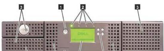
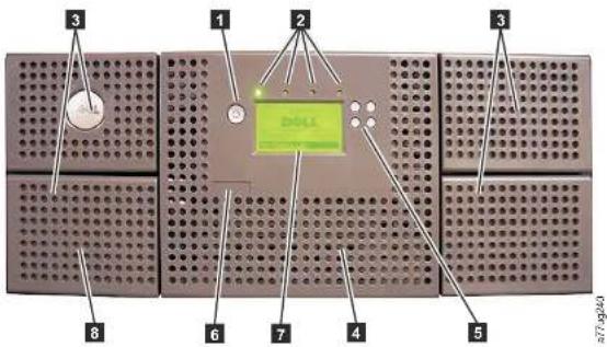
Figure1-2.Frontpanelofa4Ulibrary
Table1-1 below contains front panel descriptions for both the 2Ulibraryin Figure 1-1 on page 1-1 and the 4Ulibraryin Figure -2.
Table1-1.2Ulibraryand4Ulibraryfrontpaneldescriptions
| NumberItemDescription | ||
| 1 | Power button | Pressing this button powers ON the library. Pressing and holding this button for 4 secondswillpowerOFFtheunit(softpowerdown).Nopowerswitchorbuttoncan befoundonthebackpanelofthelibrary. |
| 2 | Frontpanel LEDs(left right) | Ready/Activity (Green LED) - It is illuminated any time the unit is powered ON and ableto function.Itshouldblinkwheneverthereislibraryordriveactivity,orwhen thelibraryisintheprocessolpoweringup.Clean Drive (Amber LED) - It is illuminated when the drive needs to be cleaned.TheLEDwillbeTurnedOFFafterthedriveiscleanedsuccessfully.Attention (Amber LED) - It is illuminated when there has been a failure that indicatesapieceofmediaisincompatiblewiththedrive,damaged,marginal,or invalid.Itwillbeclearedwhenallinvalidcartridgeshavebeenexportedfromthe library.TheamberLEDmayalsobelitbecauseapowersupplyorapowersupply |
| 5 | Controlkeys | • UP (x) - The upper left button is used to scroll upward through menu items.• DOWN (v) - The lower left button is used to scroll downward through menu items.• CANCEL (X) - The upper right button is used to cancel a user action and return to thepreviousmenuscreen.• SELECT (v) - The lower right button is used to display a sub-menu or force an accessoraction. |
| 7 | OperatorControlPaneldisplay | Thiscomponentisa128X64monochromegraphicdisplay. |
| 8 | I/O Station | The Input/Output (I/O) Station is used to import and export cartridges into and out ofthelibrary.•The2Ulibraryhasanelective1-slot/OStation.•The4Ulibraryhasanelective3-slot/OStation. |
RearPanel
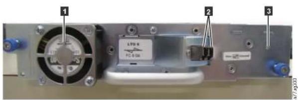
Figure1-3. Rearpanel(drivesledonly) of a half-height Fibre Channel drive


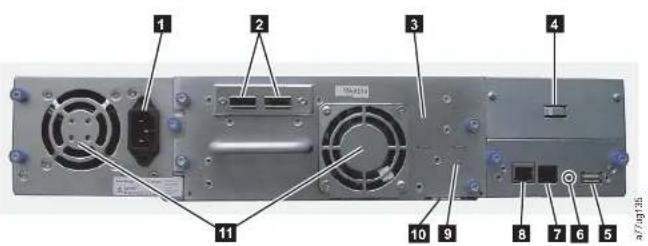
Figure1-5. Rearpanelofa2UlibrarywithafullheightdualportSASdrive
Table1-2.2 Library and 4 Library rear panel descriptions
| NumberItemDescription | |
| 1 Powerconnector(s)Bothlibrariesrequireca110/220voltACpowerconnection. •The2Ulibraryhasonepowersupply. •The4Ulibraryhasaminimumotionpowersupply,buthasthecapabilityof addingarcdundantpowersupply. | |
| 2 Hostinterface connectors | Thelibraryhasoneormoreofthefollowinghostinterfaceconnectorsonthedrive sled: •FibreChannelconnector •SFF-8088mini-SASconnector |
| 3 Tape drive sled | This library supports the Ultrium 3, 4, 5, and 6 tape drive. The tape drive in the libraryispackagedinacontainercalledadrivesled.Thedrivesledisacustomer rcplaccablecunit(CRU),andishot-pluggable,whichisdesignedforeasyremoval andreplacement. |
| 4 Shippinglockand labelstorage location | Theshippinglock,whichsecurestheaccessorduringshipping,andassociated labelaarestoredontherecarpanclothelibrary.furfutureusc.Scc"Removingand StoringtheShippingLock"onpagei-4. Note:TheshippinglockmusteremovedbelorepoweringONthelibraryto allowthaccessortofunctionproperly. |
1.14B. call lead times / 2013-11:15:00:00/1:00:00:00/1:00:00:00
Table1-2.2Ulibraryand4Ulibraryrearpaneldescriptions(continued)
| NumberItemDescription | ||
| 8 | EthernetportThisportisusedtoconnectthelibrarytoanetwork.LED•10/100Link-Description:Green:LinkIntegrity-Flashing:Networksynchronization/negotiation-Steady(On):Goodconnection-Off:NoconnectionbtewccnNICandhub•Activity-Description:Amber:Porttrafficindicator-Flashing:Networktrafficpresent-Steady(On):Heavynetworktraffic-Off:Notraffic | |
| 9 | Tape drive LED | This LED indicates the current status of the drive. When the LED is green, it indicatesnormaldriveactivity. |
| 10 | ServiceTag/Serial Number | Theservicetagandserialnumberonthepull-outlabellinkstelibrarytoyour warranty. |
| 11 | FanventsTheseeventsallow | airtoescapefromthepowersupplyandtapeadrivesled. |
BarCodeReader
Thebarcodereaderisanintegralpartofthelibraryaccessor.Thebarcodereader providesinventoryfeedbacktothehostapplication,OperatorControlPanel display,andWebUserInterfacebyreadingcartridgebarcodelabels.Thelibrary storesthecustomizedinventorydatainmemory.
Library firmware supports a 6 or 8 character volume serial number (VOISER) on thebarcodelabelonthetapecartridge.Barcodeselectionisavailableforlibraries withlibrarycode4.50orgreater.

CAUTION:
The library must be off line from any user and all media must be removed from the drives before license keys are installed or any
configurationmodificationsaremade.Pleasereferto"PowerON/OFF"
onpage2-4and"RemovingCartridgesfromMagazineSlots"onpage
9-1 forinstructionstotakethelibraryofflineandtoejectmediafrom
thedrives.
Topreventpossibledatalossduetoakeymanagementserverfailure,Dell recommendstheuseofaprimaryandsecondarykeymanagementserver.This configurationprovidesredundancyintheeventtheprimarykeymanagement serverisdownorunavailable.PleaserefertoIBM5KLMKnowledgeCenteronline athttp://www-01.ibm.com/support/knowledgecenter/SSWPVP/welcome?lang=en forinformationonconfiguringaprimaryandsecondarykeymanagementserver foryourlibrary.
If the backup job fails due to a key management server failure, the job recovers if connectivity is restored to the key management server prior to expiration of the time outset in the tape backup software application.
Enablinglibrary-managedencryptiononaPowerVaultTL2000orTL4000isa6stepprocess.
-
Upgradethelibraryanddrivefirmwaretothelatestversions. The firmware can befoundat http://support.dell.com.
-
Enablelibrary-managedencryptiononthelibraryviathelicensekeyifnot alreadylicensed.Pleasereferto"ConfigureLibrary:Encryption"onpage5-46 foractivationinstructions.
If you purchased library-managed encryption at the time you purchased your
library.ahardcopyofthelicensekevisprovidedwithyourlibraryvasa
backup.Ifthereareanyissueswiththelicensekeyforlibrary-managed
encryptionpurchasedwiththelibrary,pleasevisithttp://www.dell.com/
tapeautomationtoobtainyourlicensekey.Youwillneedthelibraryserial
numberandworldwidenodenametoobtainthelicensekey.Pleaserefertothe
followingtablesinthisdocumentforinstructionsonlocatingthisinformation:
•Table1.2forlibraryserialnumber
SupportedInternetProtocols
ThelibrarysupportsthefollowingInternetprotocols:
•IPv4
•IPv6
TolearnmoreaboutInternetprotocols,visithttp://www.iana.org/.
SNMPMessaging
Occasionally, the library may encounter as ituation that you want to know about, such as an open magazine or a full that causes the library to stop. The library provides a standard TCP/IP protocol called Simple Network Management Protocol (SNMP) to send alerts about conditions (such as need for operator intervention) over TCP/IPLAN network to an SNMP monitoring station. These alerts are called SNMP traps. Using the informations supplied each SNMP trap, the monitoring station (together with customer-supplied software) can alert operations personnel of possible problems or operator intervention that occur.
SNMPTraps
SNMPtrapsarealertsstatusmessagesthatcanbecollected,monitored and usedtoproactivelymanageattachedlibrariesusingSNMPprotocolwiththehost server(s).Insummary,eachtrapprovidesthefollowinginformation:
- Product Identification such as product name, description, manufacturer, model number, firmwarelevel, and the URL that the trapis designated for.
- Product Status such as the severity of the trap, status (current and previous) and the timethetrapoccurred.
- Library State (physical device status) such as identification and status of devices that are monitored. In the case of the library, it would include enclosure, power supply, controller, magazinestatus, drive count, cartridges lot count, and I/O station count. Also included would be certain library statistics, and where appropriate, the fault FSC (fault symptom code) including these severity and description of that fault.
- Drive Status such as the identification of each drive in the library, firmware
MaximumLibraryStorageCapacityandDataTransferRate
Maximumlibrarystoragecapacityandmaximumdatatransferratesareasfollows:
Table1-3. Tapedrivemodelandhostinterfacetype
| TapeDriveModelHostInterface | |
| Ultrium6FullHeightandHalf Heightdrives | •8Gb/sFibreChannel-singleport•6Gb/sSerialAttachedSCSI(SAS)-dualport |
| Ultrium5FullHeightandHalf Heightdrives | •8Gb/sFibreChannel-singleport•6Gb/sSerialAttachedSCSI(SAS)-dualport |
| Ultrium4FullHeightdrives | •4Gb/sFibreChannel-singleport•3Gb/sSerialAttachedSCSI(SAS)-dualport |
| Ultrium4HalfHeightV2drives | •8Gb/sFibreChannel-singleport•6GB/sSerialAttachedSCSI(SAS)-dualport |
| Ultrium4HalfHeightdrives | •3Gb/sSAS-singleport |
| Ultrium3FullHeightdrives | •Ultra160(SCSI.VD)(dependingondrive;single-ended(SE)isnot recommendedasitwillseverelydegradeperformance)•4Gb/sFibreChannel-singleport |
| Ultrium3HalfHeightV2drives | •6GB/sSerialAttachedSCSI(SAS)-dualport |
| Ultrium3HalfHeightdrives | •3Gb/sSAS-singleport |
Table1-4. Library storage capacity and datatransferrate
| Characteristic2ULibrarySpecification4ULibrarySpecification | ||
| Maximumstoragecapacity-Ultrium6DataCartridges | •24datacartridges•Native:60TB•Compressed:150TB(2.5:1 compression) | •48datacartridges•Native:120TB•Compressed:300TB(2.5:1 compression) |
| Maximumstoragecapacity-Ultrium5DataCartridges | •24datacartridges•Native:36TB | •48datacartridges•Native:72TB |
| Sustainednatedatransferr rate | LTO3HH:60MBs,LTO3HHV2:80MBsL TO 3 F H : 8 0 M B sLTO4HHandFH:120MBsLTO5:140MBsLTO6:160MBs | |
UltriumTapeDrives
This library supports the Ultrium 3,4,5, and Tape Drives. Each taped drive in the library is packaged in a container called a drives led. The drives led a customer replaceable unit (CRU), and is designed for quick removal and replacement in the library.
The Ultrium6 Tape DrivesupportstwoSASSFF-8088 connectors, oroneLC Fibre Channel connector. The SFF-8088 SAS connectors on the Ultrium6 taped drives are compatible with SAS-1 or SAS-2 cables.
The Ultrium5 Tape DrivesupportstwoSASSFF-8088 connectors, oroneLC Fibre Channelconnector. The SFF-8088 SAS connectors on the Ultrium5 taped drives are compatible with SAS-1 or SAS-2 cables.
The Ultrium4FullHeightTapeDrivessupportSAS,orFibreChannelinterfaces.It featurestwoSFF-8088SASconnectors,oroneLC FibreChannelconnector. The Ultrium4HalfHeightTapeDrivessupportsoneSASSFF-8088connector.The Ultrium4IalfIighV2TapeDrivessupporttwoSFF-8088SASconnectors,orone LC FibreChannelconnector.TheSFF-8088SASconnectorsontheLltrium4tape drivesarecompatiblewithSAS-1cables.
natural_image
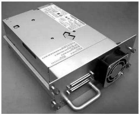
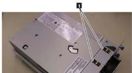
Exterior view of a power supply unit (no visible text or symbols)Figure1-6.LibrarydrivesledwithoutESDsprings(SCSIsledshown)
PowerManagement
The Ultrium3, Ultrium4, Ultrium5, and Ultrium6 TapeDrive's power management function controls the drive 'selectronics so that part of the electronics completely turn OFF when circuit functions are not needed for the drive's operation.
Media
The library uses Ultrium Tape Cartridges that provide upto 2500GB native capacity (upto6250GB with 2.5:1hardwaredatacompression) for LTO6 Tape Drives, upto 1500GB Native capacity (upto3000GB with 2:1hardwaredata compression) for LTO5 taped drives, upto 800GB native capacity (upto1600GB with 2:1hardwaredata compression) for LTO4 taped drives, and upto 4000GB native capacity (upto800GB with 2:1hardwaredata compression) for LTO3 tape drives.
Ultrium6TapeDrivescanreadandwriteL.TOUltrium6DataCartridges.Ultrium6tapedrivescanreadandwriteLTOUltrium5DataCartridgesoriginalUltrium5capacities, and canalsoreadLTOUltrium4DataCartridges with improved datarates.Ultrium5tapedrivescanreadandwriteLTOUltrium5Data Cartridges.Ultrium5tapedrivescanreadandwriteLTOUltrium4Data CartridgesoriginalUltrium4capacities, and canalsoreadLTOUltrium3Data Cartridgeswithimproved datarates.Ultrium4tapedrivescanreadandwriteLTOUltrium4Data Cartridges.Ultrium4tapedrivescanreadandwriteLTOUltrium3DataCartridgesoriginalUltrium3capacities, and canalsoreadLTOUltrium2DataCartridgeswithimproved datarates.Ultrium3TapeDrivescan readandwriteLTOUltrium3Data Cartridges.Ultrium3TapeDrivescanread andwriteLTOUltrium2DataCartridgesoriginalUltrium2capacities, and canalsoreadLTOUltrium1Data Cartridgeswithimproved dataratesofupto20 MB/secondnatedatatransferrate(40MB/secondwith2:1compression).
Note: Ultrium4tapedrivescannotreadorwritetoUltrium1tapes.Ultrium5tapedrivescannotreadorwritetoUltrium1orUltrium2tapes.Ultrium6tapedrivescannotreadorwritetoUltrium3,Ultrium2andUltrium1tapes.
Library Specifications
Physical Specifications
Table1-5. PhysicalSpecifications
| Specification2Ulibrary4Ulibrary | ||
| Height | Rackmount87.6mm(3.44in), stand-alone97.6mm(3.84in) | Rackmount175.2mm(6.9in), stand-alone185.2mm(7.3in) |
| Width447.5mm(17.6in.)447.5mm(17.6in.) | ||
| Depth | Rackmount740mm(29.13in), stand-alone810mm(31.9in) | Rackmount740mm(29.13in), stand-alone810mm(31.9in) |
| Weightwith1driveandwithout media15.59kg(34.37lbs.)21.32kg(47lbs.) | ||
| Weightwithmedia20.67kg(45.57lbs.)31.71kg(69.9lbs.) |
Power Specifications
Table1-6.PowerSpecifications
| ACpowervoltage100-127VAC;200-240VAC(4-2A) | |
| Linefrequency50-60Hz |
Operation Specifications
Table1-7. OperationSpecifications: Ultrium6
| Librarywith Ultrium6drive(s) | 2ULibrary4ULibrary | |
| Maximumstorage capacity | Maximumnumber of datacartridges: 24 Native: 60TB Compressed: 150 TB(2.5:1 compression) | Maximum numberof datacartridges: 48 Native: 120TB Compressed: 300 TB(2.5:1 compression) |
| Number of slots | 24 (including I/O Station) | 48 (Including 3 I/O Station slots) |
| Sustainednative datatransferrate | Ultrium 6Drive: 160MB/s | |
| Librarywith Ultrium5drive(s) | 2ULibrary4ULibrary | |
| Drivctypes | Ultrium5FullHeightDrive: FibreChannel,SASUltrium5HalfHeightDrive: FibreChannel,SAS | |
| Interfaces | 8Gb/sFibreChannel6Gb/sSAS | |
| *HostInterfaceDriveTransferRatesmayvarydependingonhostusageandinterfaceutilization. | ||
Table1-9. Operation Specifications: Ultrium4
| Librarywith Ultrium4drive(s) | 2ULibrary4ULibrary | |
| Maximumstorage capacity | Maximumnumberofdatacartridges:24Native:19.2TB Compressed:38.4TB(2:1compression) | Maximumnumberofdatacartridges:48Native:38.4TB Compressed:75.2TB(2:1compression) |
| Numberofslots24(including1/OStation)48(Including31/Ostationslots) | ||
| Sustainednative datatransferrate | Ultrium4FullHeightDrive:120MB/sUltrium4HalfHeightDrive:120MB/s | |
| Drivetypes | Ultrium4FullHeightDrive:FibreChannel,SASUltrium4HalfHeightDrive:SAS,FibreChannel | |
| Interfaces | Ultrium4HIFibreDriveV2(8Gb/s)Ultrium4HH5ASDriveV2(6Gb/s)4Gb/sFibreChannel3Gb/sSAS | |
| *HostInterfaceDriveTransferRatesmayvarydependingonhostusageandinterfaceutilization. | ||
Table1-10. OperationSpecifications: Ultrium3
| Librarywith Ultrium3drive(s) | 2Ulibrary4Ulibrary |
EnvironmentalSpecifications
Table1-11.EnvironmentalSpecifications
| Temperature | |
| Operating 10^ to 35^ ( 50^ to 95^ ) | |
| Storage,withoutcartridges- 30^ to 60^ (- 22^ to 140^ ) | |
| Wetbulb,operating 26^ ( 79.0^ )maximum | |
| Temperatureshockimmunity-maximumratcofchange 10^ ( 18^ )perhour | |
| Miscellaneous | |
| Dustconcentrationlessthan200microgram/cubicmeter | |
| MaximumacousticalnoisesoundpowerlevelsLwAdinbcls6.6/6.8 | |
| Humidity | |
| Operating 15% to 80% RHnon-condensing | |
| Storage,withoutcartridges 10% to 90% RHnon-condensing | |
ProductEnvironment
The library is designed to operate in general business environment.
The library meets the acoustical requirements for general business area category 2D. Category 2D state that the library should be installed at minimum of 4 m (13 ft.) from a permanent workstation.
Toallowforserviceaccess, install the library a minimum of 0.9m(3ft.) from all obstacles.
The library is a precision computer peripheral. To ensure maximum longevity of your library, locate the library away from dust, dirt, and airborne particulates. • Keep the library away from high-traffic areas, especially if the floor is carpeted. Carpeting harbors dust and people walking on the carpet can cause the carpet fibers and the dust to become airborne. • Keep the library out of printer or pier room because of flower and paper dust
Chapter2.UserInterfaces
Thislibraryhastwouserinterfaces.
•OperatorControlPanel-locatedonthefrontpanelofthelibrary
- "WebUserInterface" on page 2-4 - accessed via a web browser
OperatorControlPanel
TheOperatorControlPaneloperatesintwobasicmodes.
- User Interaction mode - This mode is employed when a user is pushing buttons ontheOperatorControlPanel.
- System Driven mode - This is the normal mode of operation. In this mode, the OperatorControlPaneldisplaystatusassociatedwiththeactionsthatwere causedfromcommandssissuedviathedrive'sinternal(drivetolibrary)serial interface.
When an Operator Control Panel button is pressed and released, the Operator Control Panel automatically transitions to User Interaction mode. User Interaction mode will continue until 3 minutes after a user stop pushing buttons, or the requested accessor action stops whichever is longer. At which time, the Operator Control Panel will return to System Driven mode.
Innecessary, theOperatorControlPanelautomaticallytransitionstotheSystemDrivenmode. Whenthiscours, thelibrarymustrememberthepreviousfunction beforesetdisplaymodechanged. ThereforethenextbuttonpressedonlytransitionstheOperatorControlPaneltotheUserInteractionmodefromtheSystemDrivenmode.
In case of the activated user security feature, the User Interaction mode is restricted to Login and Monitor menu items, until a user logs in with a correct password.
becomeilluminated. The error coderemainson theOperatorControlPanel until apushbutton is pressed, which cause theOperatorControlPanel to return to the HomeScreen.
- Numericerrorcodesareonlyusedforunrecoverable,fatalerrors,otherwisetext statusmessagesarcdisplayed.
Power-ONDisplay
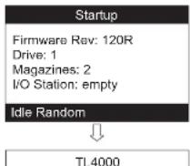
WhenthlibrarypowersONorresets,itgoesthroughseveralinternallycontrolled processessthatallowittogenitializedanddrumming. Theseprocessesarecalled Power-On-Self-Test(POST).DuringthePOSTtheOperatorControlPaneldisplays informationthatmaybemeaninglessuntilPOSTiscomplete.WhenthePOSTis finished,thelibrarydisplaystheStartupscreen,thentheHomescreen.
The StartupscreenisthefirstscreenthatappearsafterpoweringONthelibrary.It contains the following information:
•FirmwareRev: the current level of library firmware
•Drives: the total number of drivesthat the library cansupport
•Magazines: the total number of magazines in the library
•I/OStation: thecurrentstatusoftheI/OStation
While the library is going through its power cycle you can monitor the state of the library via the OCP; however, you may not be able to make any configuration changes until the unithas completed its initialization routine. Attempt to make changes will be ignored.
The following are additional operational detail of LEDs:
- The Ready/Activity LED is illuminated any time the unit is powered ON and functional. The Ready/ActivityLEDblinkswheneverthereislibraryordrive activity. This LED will also blink when the unit is OFFLINE.
- The Clean LED is illuminated when either a cleaning requested or a cleaning required flag has been issued by the drive. The LEDisturnedoff after a successful drive cleaning operation.
•TheAttentionLEDindicatesoneofthefollowingconditions.
| ProblemActionRequired | |
| Badmedia | 1. Go to Monitor > Inventory to locate the defective cartridge.2.MovethedefectivecartridgetotheI/OStation.(OperatorControlPanel:Control>Move Cartridges).3.Openthel/OStationtoremovethedefective cartridge.(OperatorControlPanel:Control>Open I/O). |
| DrivesledissuesDooneofthefollowing: | -Installadrivesled(see"Removing/Installing/Adding TapeDriveSled"onpage10-3).-ModifyorresubmitLogicalLibrarysetting(Operator ControlPanel:Configure>LogicalLibrariesorWeb UscInterface:ConfigureLibrary>LogicalLibraries).-Restoredefaults(OperatorControlPanel:Configure>RestoreDefaultsonWebUserInterface:Configure Library>RestoreDefaults). |
| RedundantpowersupplyfailedCompletecthfollowingsteps: | 1.Replacethefailedpowersupply(see"Replacing PowerSupply"onpage10-10).2.Cyclelibrarypower. |
|Davonwertesli: Faréchine/Davonwertesli
- Using the UP and DOWN buttons, select one of the various predefined values for that item.
- As soon as the Operator Control Panel display shows the correct value, press the SELECT button to apply the value.
TogglingValues
Toggle values are used to switch between two different states like ON and OFF.
- After navigating to the menu item, press the SELECT button to select the menu item.
- Using the UP and DOWN buttons, select one of the various predefined states for that item.
- Press the SELECT button to apply thenew state.
EnteringNumericalValues
Numerical values are needed for network addresses, password entries and other configuration entries.
1. After navigating to the menu item, the current value is displayed and the cursor highlights the first digit of the value that can be changed.
2. Foreachdigittobechangedinthevalue:
a. Use the UP and DOWN button to increment/decrement the digit.
b.PresstheSELECTbuttontohighlightthenexteditabledigit.
- Press the SELECT button at the last digit to apply the complete entry, or press the CANCEL button to cancel the whole edit process and maintain the original value.
PowerON/OFF
PartoftheOperatorControlPanelisthePowerON/OFFbutton. If thelibrary is powered ON, pressing this button for second swill initiate a controlled power down of the library (soft landing). The following operations will take place before the library shuts down completely:
- Thedisplayindicateswithanappropriatemessagethattheshutdownisin progress.
•Thelibrarycontrollerfinishesallongoinglibraryanddriveactivities.
UserInterface,youmustfirstsettheIPaddressusingtheOperatorControlPanel. Referto'Configure:Network'onpage5-23or"ConfigureLibrary:Network"on page5-45.
Login
Important: Some options of the Web User Interface takethelibrary OFFLINE. This inactivemodecaninterferewithhost-based application software, causing dataloss. Makesurethelibrary is idle before attempting to perform any remote operations that will takethelibrary OFFLINE.
Tologin,selecttheRoletypeandenterthecorrectpassword.TheTL4000/TL2000 RMUscreenshowsWelcome:User,superuser,admin,orserviceafterasuccessful login.Theusercanlogoutatanytimebyclickingonthe"logout"textlocatedin totoprightcorneroftheRMUpage.
•TheUseronlyhasaccesstoMonitorLibrarymenus. TheUseracconthasonly viewingprivilegestothecunit,notabletomakeanyconfigurationchanges.
•Superuser-TheSuperuserhasaccesstotheMonitorLibraryandManage Librarysections.
•TheAdminuserhasaccesstoallmenusexceptthoserestrictedtoService only. TheAdminaccounthasaccesstomonitor,configureandrununit diagnostics(onlyexceptionistheadadvanceddiagnosticsreservedforservice personnelonly).
•Servicepersonnelhaveaccesstoallmenus.TheServiceaccounthasallthe sameprivilegesastheAdminaccountwiththeadditionofadvancedunit diagnostics.
Note:UserandSuperuseraccountsmustbeenabledbythelibrary administrator.Theseaccountsaredisabledbydefault.
Note: Passwordsarecase-sensitive.
Use the following password for logging in an Adminuser: secure
Eachlevelaffectswhichareasyouhaveaccesstoandwhatactionsyoucaninitiate
otherIPv6address).
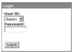
Figure2-2.WebUserInterface login page
SystemStatus
The System Status screen is always present after logging giving current status of the library.
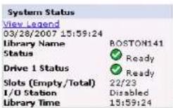
Figure2-3.2 Library System Status screen
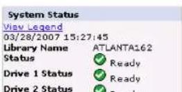
v If Auto Clean is enabled and a cleaning cartridge is not present, or if a cleaning cartridge is present, but not in a reserved slot, Auto Clean status will show Chk Media/Rsvd Slot? and Status will show a green check mark and the words Media Attention. The Auto Clean status disappears from the system status screen once Auto Clean has been properly configured. You will get messages if the cleaning media expires.
Figure 2-5. 4U library System Status screen showing media attention status
v The Power Supply Status will only appear if redundant power is being utilized with a 4U library, and the library was manufactured after March 14, 2008. If a redundant power supply fails, the System Status screen will appear as shown in Figure 2-6.
If your library has -05 level redundant powers supplies, the "Green" LED will be Nonboth powers supplies. If both "Green" LEDs are not ON,
replacethefailedpowersupply(referto"ReplacingaPowerSupply" on page10-10).
WebUserInterfaceHelpPages
EachscreenontheWebUserInterfacehasanassociatedHelppage.Toaccessa
Helppage,clickonHelpintheupperrightcornerofthescreen.Anewwebpage
willopen.Usingthelefthavigationpane,selectthedesiredHelppage.Toclosethe
Helppage, clickthered Xintheupperrightcornerofthescreen.
LoggingoutoftheWebUserInterface
TologoutoftheWebUserInterface,clickLogoutintheupperrightcornerofthecurrentscreen.
Important: If you click the X in the upper right corner of your internet browser window, you will not log out of the WebUserInterface.
Chapter3.InstallationPlanning
Beforeinstallingyourlibrary,taketimetoreviewthefollowinginformation.
DeterminingtheNumberofLogicalLibraries
Youcanpartitionthelibraryintoasmanylogicallibrariesastherearedrivesinthe library.
BasicGuidelines
•Each logical library must contain at least one drive.
- Alibraryconfigurationofexactlyonelogicallibraryequalstheentirephysical library.
• Thelibraryissuesawarningtotheuserifmediaismovedacrosslogical libraries.
LibrarySharing
The library default configuration allows single application to operate the library through a single control path. Often, it is advantageous to be able to share a single library between heterogeneous (dissimilar) or homogeneous (similar) applications. Some applications (and some servers) do not allow for sharing a library between systems. Configurations can be created that enable the library to process commands from multiple heterogeneous applications and multiple homogeneous applications.
From the library's WebUser Interface or Operator Control Panel, the following actions can be performed:
- Configurethelibrarysothatitispartitionedintoseparatelogicallibraries that independentlycommunicatewithseparateapplicationsthroughseparatecontrol paths. This configurationrequiresnospecialcapabilitiesfromtheserveror application.(Formoreinformation,see"UsingMultipleLogicalLibrariesfor
UsingMultipleLogicalLibrariesforLibrarySharing
Multiplelogicallibrariesareaneffectivewayforthelibrarytosimultaneouslyback upandrestoredatafromheterogeneousapplications. Forexample, thelibrarycan bepartitionedsothatitprocesses:
•CommandsfromApplicationA(aboutDepartmentX)inLogicalLibrary1
*CommandsfromApplicationB(aboutDepartmentY)inLogicalLibrary2
In this configuration, the storageslots and drivesineachlogical library are dedicated to that library and are not shared among other libraries. Commands issued by the application travel to the library through two unique control paths. Thus, the dataprocessing for:
•DepartmentXisconfinedtothestorageslotsanddrivesinLogicalLibrary1
•DepartmentYisconfinedtothestorageslotsanddrivesinLogicalLibrary2
UsingMultipleControlPaths
Inaddition to creating multiple logical libraries, any logical library can be configured to have more than one control path. When configuring additional control paths, additional library sharing configurations and availability options are made possible. Access to the logical library is on first-come, first-served basis and each control path for logical library can accept commands while the library is in use by another control path. By default, only the first drive logical library will be un-labeled.
Foraparticularlogicallibrary,youcanenableasmanycontrolpathsasthereare drivesinthatlogicallibrary.
UsingMultipleControlPathsforPathFailover
Commandfailuresandtimeoutsarecostly.Youwantyourlibrarytorunsmoothly andefficiently.Toensurecontinuedprocessing,thelibraryoffersanoptionalpath failoverfeaturethalenablesthehostdevidedrivertoresendthecommandtoan alternatecontrolpathforthesameclogallibrary.Withcontrolpathfailover installed,thealternatecontrolpathcanincludeanotherHIBA,SAN,orlibrary controlpathdrive.Thedevidedriverinitiateserrorrecoveryandcontinuesthe
LibraryPartitioningandElementAddressing
Library4Usystemswithfirmwareversionsof.80andhigher,andcontainingat least2drives,havetheabilitytoconfiguretwologicallibraries(createtwo partitions).Thispartitioninghasbeenexpandedwiththenewlibraryfirmwareand half-highdriveintegration.Nowitispossibletoconfigure1,2,3or4partitionsin the4ULibrary.Additionallythe2ULibrarycannowbeconfiguredintooneortwo partitions.Eachlibrarymustcontainatleastastonedriveperlogicallibrary (partition).Inapartitionedlibrary,theOperatorControlPanel(OCP)onlyreports thestatusofologicallibrary1inthemainmenduetospacelimitations.Theuser mustnavigatetothelogicallibrariesstatusintheOCPtogetheinformationon theadditionallibrarypartitions.
Partitioningof2ULibraries
Whentwohalfheightdrivesareinstalledina2Ulibrary, thelibraryfirmwarewill supportpartitioninginthesamewaythatthe4Usupportpartitioningwithtwofullheightdrivestoday.Thefirstpartitionwillcontainthefirstmagazineandthefirstdrive.Thesecondpartitionwillcontainthesecondmagazineandtheseconddrive.The1/Ostation(ifconfiguredas1/O)willbeshared,asisdonewiththepartitioned4Ulibrary.
Onefullheightdriveis "Drive1".Whenusinghalfheightdrives, thefirsthalf heightdrivepositionwillbecalled "Drive1", Thesecondhalfheightdriveposition willbecalled "Drive2."
Partitioningof4ULibraries
Whenoneormorehalfheightdrivesareaddedtoa4Ulibrary,thedrivenaming willchange.Currently, thefirstfullheightdriveis"Drive1"andthesecondfull heightdriveis"Drive2".Whenyouconsider thateachfullheightdriveslotmay containoncortwohalfheightdrives,therecarefourpotentialdrivesinthespace thatusedtooccupytwo.Asaresult,thefirsthalfheightdriveposition,orthefirst full-highdriveposition,willbecalled"Drive1".Thesecondhalfheightdrive positionwillbecalled"Drive2".Thethirdhalfheightdriveposition,orthesecond fullheightdriveposition,willbecalled"Drive3".Thefourthhalfheightdrive
Configurationofa1-PartitionSystem
Aonepartitionsystemconfiguredfora4Ulibrarycontainsanyandalldrives presentinanydrivepositions,anditwillcontainallfourmagazines.
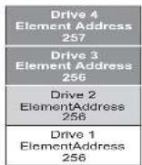
When configured with oncological partition, the Element Address assignments will be as follows: DTEassignments will be as shown in Figure 3-1.
STEassignments:
- LogicalLibrary1:Slot1through234096(0x1000)through4118(0x1016)as showninFigure3-4onpage3-5
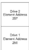
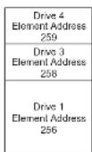
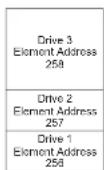
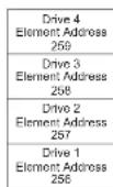
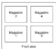
Figure3-1. Configuration of a one-partition system
Configurationofa2-PartitionSystem
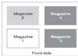
At twopartitionsystemmusthaveatleasttwodrivesinstalled. Onedrive mustbe installedineitherdriveposition1ordriveposition2, andanotherdrivemustbe installedineitherdriveposition3ordriveposition4. Partition1containsany drivesindriveposition1anddriveposition2. Partition1willalsocontain magazine1andmagazine2. Partition2containsanydrivesindriveposition3and driveposition4. Partition2willalsocontainmagazine3andmagazine4.
When configured with twological partitions, the Element Address assignments will be as follows: DTE assignment will be as shown in Figure 3-2.
Configurationofa3-PartitionSystem
Athreepartitionsystemmusthaveatleastthreedrivesinstalled. A drivemustbe installedindriveposition1,anotherdrivevmustbinstalledindriveposition2, andanotherdrivemustbeinstalledeitherdriveposition3ordriveposition4. Partition1willcontainthefirstdriveandthefirstmagazine.Partition2will containtheseconddriveandthesecondmagazine.Partition3willcontainany drivesindriveposition3anddriveposition4.Partition3willalsocontain magazine3andmagazine4.
STEassignments
•LogicalLibrary1:Slot1throughslot94096(x1000)through4104(0x1008)
•LogicalLibrary2:Slot10throughslot214096(x1000)through4107(0x100B)
•LogicalLibrary3:Slot22throughslot454096(x1000)through4119(0x1017)
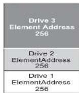
077ug183
Figure3-3. Configuration of three-partition system
Configurationofa4-PartitionSystem
Afourpartitionsystemmusthavefourdrives.Eachpartitioncontainsonedrive andonemagazine.
When configured with four logical partitions, the ElementAddressassignments will be as follows: DTEassignmentswillbeasshowninFigure3-4.
SCSIElementAddressing
Everylogicallibrarystartsatthefirstdriveslotwithhecurrentassignedelementstartaddress(defaultvalue256).Itwillbeincrementedfromthebottomtothetopslotsforeverydriveslot.Thereisoneexceptiontothisaddressingschemetoaccommodatelibraricscurrentlyinthefield.A4Ulibrarycontainingonlyfullheightdriveswillcontinuethohavetheaddressesassignments256and257,thuscausingnointerruptionstothcioperation.Driveslotswillstillbeincrementedby1foreachdriveslotposition.
Note: Exchanging drives with different form factors will result in the library needing to be reconfigured.
4U Unit with only FH drives (1 logical library)
| SCSI Element Slot | |
| 257 | 4 |
| 3 | |
| 256 | 2 |
| 1 | |
4U Unit with FH and HH drives (1 logical library)
| SCSI Element Slot | |
| 258 | 4 |
| 3 | |
| 257 | 2 |
| 258 | 1 |
ATTOG163
Figure3-5. Examples of SCS lelementaddressing
TheSCSlspecificationdoesnotallowgapsintheSCSlelementaddressing.Special handlingisneededforemptydriveslotstofulfillthespecification.Also temporarilyremoveddrivesneedtohavetheiraddressespreservedtonotconfuse
LogicalUnitNumber(LUN)Scanning
ThelibraryusesasinglcsSorLoopIDperdriveandddualLUNstocontrolthe tapedrive(1.UN0)andlibraryaccessor(1.UN1).ThelibraryrequiresaHostBus Adapter(HBA)thatsupportsLUNscanning,Ifitisnotenabled,yourhostsystem willnotscanbeyond1.UN0andwillfailtodiscoverthelibrary.Itwillonlysee the tapedrive.
Important: SomeHBAs, such as RAID controllers, do not support LUNscanning.
HostInterfaces
The2Ulibraryandthe4Ulibrarycanbeattachedtoserversusingthefollowing interfaces:
•SCSI(LVDUltrium160)
- SerialAttachedSCSI(SAS)
•FibreChannel
Table3-1.HostDriveInterfaceSupport
| DriveSCSI(LVDUltra160)SA5FC | |||
| Ultrium3FHX | |||
| Ultrium3HHX* | |||
| Ultrium3HHv2X* | |||
| Ultrium4FH | X* X | ||
| Ultrium4HHX* | X | ||
| Ultrium4HHv2X* | X | ||
| Ultrium5I11X* | X | ||
| Ultrium6HHX* | X | ||
| Note:*=DualPortSAS | |||
SCSIIinterface
Note: Formaximumperformance, itisrecommended to have a maximum of onedriveperSCSIbus.
-Onlyusethemaximumsystem-to-devicecablelengthof25m(82ft)when attachingdirectlytoonedevice(apointtopointinterconnection).
Note: Daisy-chainingis NOT recommended duetopotential issues with SCSI busperformance, SCSI cables/connectors, and hostbusadapters.
PhysicalCharacteristicsoftheSCSllInterface
The library operates as a set of SCSI-3 devices. The Ultrium Tape Drives attach to servers using an LVD Ultra 160 SCSI interface. Each SCSI drives the use shielded, HD68-pin connectors, and can attach directly to a 2-byte-wide SCSI cable.
Anycombinationofuptotwoinitiators(servers)anduptofourtargets(devices)isallowedonasingleSCSIbusifthefollowingconditionsaremet:
•TheSCS1busisterminatedproperlyateachend
•CablerestrictionsarefollowedaccordingtotheSCSI-3specification
UndertheSCSI-3protocol, thistypeofattachmentallowscablelengthsofupto25 m(81ft) with the appropriate cable and terminator. Thetable below gives the maximum bus length between terminators for the LVD interface.
Table3-2. Maximumbuslengthbetweenterminators
| TypeOfInterconnection | MaximumBusLengthBetweenTerminators(in meters) |
| Point-to-point(1serverand1drive)25 | |
| Multi-drop/daisy-chain(1serverand multipledrives) | 12(LVD) |
| Note:Themaximumbuslengthsstatedinthistableincludetheinternallengthofthebus. | |
Formaximumperformance,multipleSCSibusesmayberequired(see"Using MultipleSCSIBuses"),andUltriumTapeDrivesmustbetheonlytargetdevices thatareactiveonthebus.
Note: Daisy-chaining is NOT recommended due to potential issues with SCSI bus performance, SCSI cables/connectors, and host bus adapters.
RemovalofanyjumperswillcreatcaSCS1busforeachdrivecinstalledinyour libraryforattachementtomultipleserversortomultipleSCSIadaptercardsonone server.RememberthatcachSCS1busmustbeterminated.MultipleSCS1buses mayberequiredformaximumperformance,dependingonthapplicationand datacompressionratio.Note,however,thatlibrary(MediumChanger)controls requiredonatleastaneSCS1bus.
The MediumChanger device is required to be addressed via LUN1 of the lowest-numbered drive position of each logical library. The MediumChanger devicemay additionally be addressed via LUN1 of other drives in any logical library.
AnybuscontainingaMediumChangerdeviceviaLUN1ofadriveisreferredto asacontrolanddatapath.Anyotherbusisreferredtoasadatapath.For informationaboutcontrolpaths,see"UsingMultipleControlPaths"onpage3-2.
TerminatingtheBus
TheSCSIbusandallofthewiresintheSCSlcablemustbeproperlyterminated according to the SCSI standard.
YoucanpluganexternalterminatorintooneoftheSCSIconnectors.Aterminator mustbeinstalledonthelastdeviceoneachendofastringofmultipledevices.A terminatorisincludedwiththeachSCSIUItriumTapeDrive.
SCSIDifferential-LVD
LVDtapedvicessupportabuslengthof25meters(82ft.)point-to-point,and12 meters(39ft.)usingmulti-dropinterconnection(daisy-chaining).Foreach daisy-chaineddevice,themaximumcablelengthmustbereducedby0.5meters (1.6ft).
Important: A faster bus does not imply that an attached device will support that datarate, but that multiple devices can operate on the bus at that maximum speed. For detailed table of SCS terms and related specifications, therefore SCS Trade Association Web site
active/passiveclusterfailover.LAN-freedrivesharingisnotsupported.Ultrium3 and Ultrium4SASdrivesledsusetheSFF-8088connectionatthedrivesledend andSFF-8088orSFF-8470atthehostadapterend.
FibreChannelInterface
FibreChannelallowsforanactiveintelligentinterconnectionscheme,calleda Fabric,toconnectdevices. EverythingbetweentheportsonFibreChanneliscalled theFabric.TheFabricismostoftenaswitchorseriesofswitchesthattakes the responsibilityforrouting.
ThelibraryallowstheselectionofthefollowingFibrechannelportbehaviors:
• LNPort:(defaultsetting)-anautomaticconfigurationthattriesarbitratedloop first, thenswitchedfabric
•LPort-arbitratedloop
•NPort-pointtopointprotocolinaswitchedfabric topology
CablesandSpeeds
Ultrium3,Ultrium4,Ultrium5,andUltrium6FibreChanneltapedrivesuseLC duplexfiberopticscables.
ThemaximumdistancesthatthelibrarysupportsonaFibreChannellinkis determinedbythelinkspeed,thetypeoffiber(50-micronor62.5-micron),andthe devicetowhichthelibraryisattached.
If the library attachestoan HBA (HostBusAdapter), refertothedistance that are supported by the HBA. If the library attachesto as switch, the supported distances are:
•Foramulti-mode50-microncable:
-1-Gbitlinkspeed=upto500m(1640ft)
-2-Gbitlinkspeed=upto300m(984ft)
-4-Cbitlinkspeed=upto175m(574ft)
-8-Gbitlinkspeed=upto150m(492ft)
•Foramulti-mode62.5-microncable:
- C_2 is a linear equation of 2 , where (0,1)
ZoningallowsyoutopartitionyourSANintologicalgroupingsofdevicessothatcachgroupisisolatedfromtheotherandcanonlyaccessthedevicesinitsowngroup.Twotypesofzoningexist:hardwarezoningandsoftwarezoning.Ihardwarezoningisbasedonphysicalfabricportnumber.SoftwarezoningisdefinedwithaWorldWideNodeName(WWNN)orWorldWidePortName(WWPN).Whilezoningcanbereconfiguredwithoutcausinganoutage,somezoningconfigurationscanbecomecomplicated.Theadvantageofthelibrary'sWWNNimplementationisthatyoucanavoidthccexposureintroducingzoningerrorsbecauseyoudonohavetochangethezoningconfigurationifadriveneedsserviceorreplacement.
SharingonaStorageAreaNetwork
WithStorageAreaNetwork(SAN)components,thepossibilitiesforconnecting multiplesystemsandmultipledriveshaveincreased.Notallsoftwareandsystems aredesignedtosharedrives.Beforeyouinstalladrivethatwouldallowtwo systemstoshareit,checkthatthesystemsandtheirsoftwaresupportsharing.If yoursoftwaredoesnotsupportsharing,notethatFibreChannelswitcheshaveca zoningcapabilitytoformaSANpartition.Forsystemsthatdonotcooperate,use zoningtopreventthesystemsfromsharingthesamedrive.Youcanremovezoned partitionsasyouupgradesoftwareandsystemlevels.
Chapter4.InstallationandConfiguration
Note: Review the information in "Installation Planning" before installing your library.
Toinstalladesktoporrackmounted2Ulibraryor4Ulibrary,performthe proceduresinthischapterintheordertheyarepresented.
UsingtheLibraryConfigurationForm
Before beginning the installation and configuration of your library, make a copy of the Appendix G, "LibraryConfigurationForm," on page G-1. Enter library information (such as serial numbers, types of drives, etc.) and configuration settings on the library Configuration Form and store in as a location for future reference. Besuretoupdate this form any time changes are made to your library hardware or configuration.
InstallingYourLibrary
Complete these procedure to install your library hardware.
- "ChoosingaLocation."
2."UnpackingtheLibrary"onpage4-2.
3."Verifyingtheshipment"onpage4-2.
4."nstallingtheLibraryFootPads(forDesktopInstallationONLY)"onpage4-3. - "RemovingandStoringtheShippingLock" on page 4-4.
- "RackmountingtheLibrary(forRackInstallationONLY)" on page 4-6.
- "ConnectingtheHostInterfaceCable" onpage4-16.
8."ConnectingaPowerCord"onpage4-18.
ChoosingaLocation
Choose allocation that meets the following criteria:
Table4-1. Locationcriteria(continued)
| CriteriaDefinition | |
| AirqualityThelibraryshouldbeplacedinanareawithminimalsourcesofparticulatecontamination.Avoidareasnearfrequentlyuseddoorsandwalkways,stacksofsuppliesthatcollectdust,printers,andsmoke-filledrooms.Excessivedustanddebriscandamagetapesandtape drives. | |
| Humidity15-80%RHnon-condensing | |
| Clearance | •Back:Minimumof13.4cm(6inches)•Front:Minimumof30.8cm(12inches)•Sides:Minimumof3.08cm(2inches) |
| RackrequirementsStandard19-inchrackwith:•2U.(88.90mm/3.5in.)ofclearancelora2Ulibrary•4U.(177.8mm/7in.)ofclearancelora4UlibraryRackmountingthelibraryisoptional. | |
UnpackingtheLibrary
- Clearaworksurfacetounpackthelibrary.
- Open the shipping container and carefully remove the shipping materials from the top of the library. Remove the accessory package and set it aside.
Note: Once the drive is unpacked, save and store the packaging materials for futuremovesorshipping.
3.1. If the library out of the carton and remove the bag from the library. Remove the foam cushion from the back of the library. Savethe packaging materials for future use.
Important: Donotplacethelibrary on the front panel or the rear panel last this may damage the library. The display should NOT be touched during the removal of the unit from the packaging.
- Remove all clear plastic protective sheets from the library.
-Barcodelabels
-Footpads(fordesktopinstallation)
- With every library that contains a SCSIdrive:
-SCSIterminator(oneperSCSIdrive)
-SCSlibrary-to-hostcable(iforderedbycustomer)
- WitheverylibrarythatcontainsaFibreChanneldrive:
-FibreChannellibrary-to-host/switchcable(iforderedbycustomer)
•With every library that contains a SAS drive:
-SASlibrary-to-hostcable(iforderedbycustomer)
•RackMountKit
Important: If your library did not contain preinstalled drives, then install them
now.Referto"Removing/Installing/AddingaTapeDriveSled"on
page10-3forinstructionsoninstallingyourtapedrives.
InstallingtheLibraryFootPads(forDesktopInstallation ONLY)
If you intend to install your library in a rack, skip this step and proceed to
"RemovingandStoringtheShippingLock"onpage4-4.
Important: Operating your library on a flatsurface without footpads may damage
yourlibraryorcauseitnottofunctionproperly.
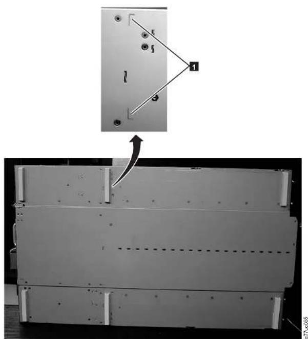
Sixfootpadsmustbeinstalledonthebottomofthelibrarybeforethelibrarycan beusedasadesktopunit.
Toinstallthelibraryfootpads:
- Being very careful, lay the library on it's side.
2.Peeltheadhesivefromthebackofeachfootpad.
3.Installthefootpadsonthebottomofthelibraryenclosurebypassingeach
footintooneofthesixareas(1)asshowninthefigurebelow.
natural_image
Mechanical assembly diagram showing a metal panel with mounting holes and a directional arrow indicating motion (no text or symbols present)Figure4-2. Installingfootpadsonthebottomofthelibraryenclosure
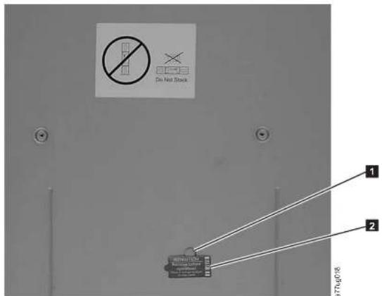
Figure4-3. Shippinglockandlabel
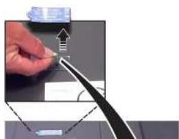
natural_image
Close-up of a hand holding a pen tip, with a magnified inset showing an upward arrow and angle (no text or symbols visible)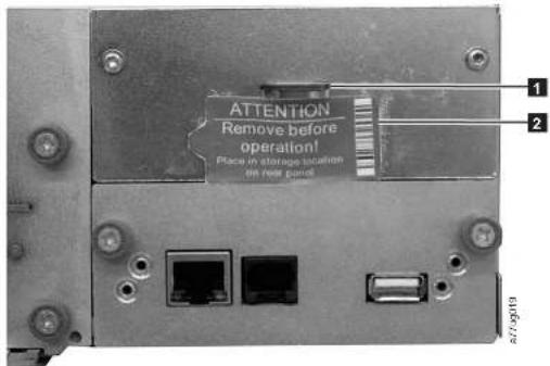
Figure4-5.Libraryshippinglockandlabelstoragelocationonrearpaneloflibrary
RackmountingtheLibrary(forRackInstallationONLY)
The2Ulibraryandthe4Ulibraryareasilyinstalledintoastandard19-inchrack system. The2Ulibraryrequires2U(3.5in.)ofspace. The4Ulibraryrequires4U(7 in.)ofspace.
If you are not track mounting your library, skip this procedure and goto "Attaching the Library to a Server" on page 4-16.
Important:A2Ulibraryweighs15.59kg(34.37lbs.)withonedriveandwithoutmedia.A4Ulibraryweighs21.32kg(47lbs.)withonedriveand withoutmedia.
Toreducetheriskofpersonalinjuryordamagetothelibrary:
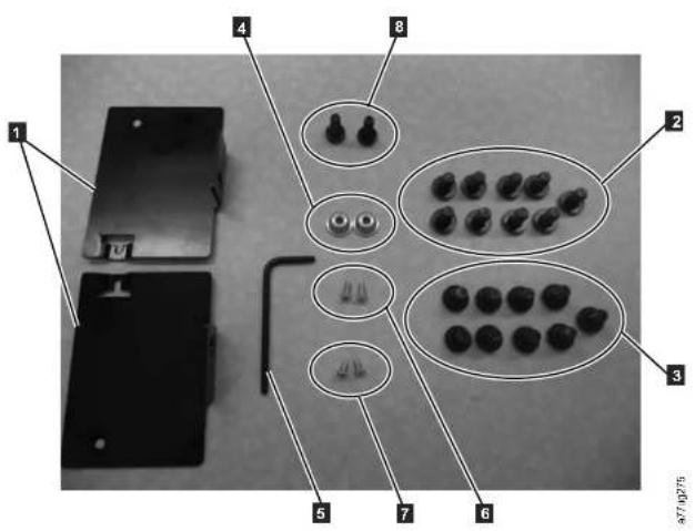
Figure4-6. RackKit Amounting hardware
a.RackKitA:ThefollowingpartsmakeupRackKitA.
•Packagedincardboardmaterial:
-2rails(notshown)SeeFigure4-9onpage4-9foragraphicoftherails.
-2mountingbrackets(1 inFigure4-6)
•Packagedinthesmallbagwithnolabel:
-1Torxwrench(5 inFigure4-6)
-2anchors(4)
-2countersunkscrewsforsecuringtheanchors(6)
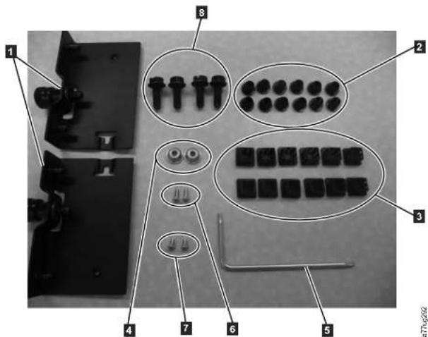
Figure4-7.RackKitBmountinghardware
b.RackKitB:ThefollowingpartsmakeupRackKitB.
•Packagedinplasticmaterial:
-2rails(notshown)See Figure 4-10onpage4-10foragraphicofthe rails.
-2mountingbracketswithcaptivethumbscrews(1 inFigure4-7)
•Packagedinsmallbagsandlabeledwithpartnumbers:
-1Torxwrench(5 inFigure4-7)
(2)
flowchart
graph TD
    A["1"] --> B["2"]
    B --> C["3"]
    C --> D["4"]
    D --> E["87.0153"]
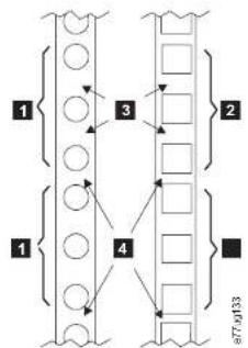
Figure4-8. Examples of EIA units for round hole and square hole installations
| 1 | TwoEIAunitsforroundholeand | 3 | WideCapswithintheEIAunit |
| 2 | 4 |
- Using the screws for your rack type (round holes or square holes) and a#2
Phillipsscrewdriverandensuringthattheflangeoneachrailpointstowardthe
othertoformashelf,secureonerailtoeachsideoftherackinyourchosen
racklocation.Secureboththefrontandbackofeachrailtotherack.The
narrowendofeachrailgoestotherearoftherack.Therailsextendtofita
varietyofrackdepths.Eachrailrequires2Uofrackspace(1 inFigure4
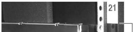
natural_image
Close-up of a mechanical component with no visible text or symbols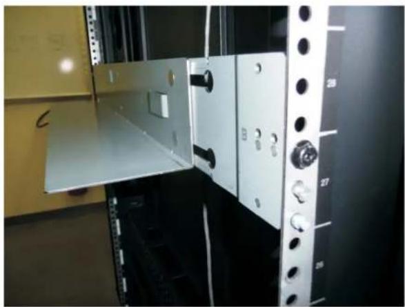
natural_image
Interior view of a server room with open door, black panel, and numbered wall-mounted buttons (no visible text or symbols)Figure4-10. RearviewofRackKitBshowsadifferentmountingmethod
natural_image
Two circular frames showing internal mechanical components, mounted on a rail-like structure (no text or symbols visible)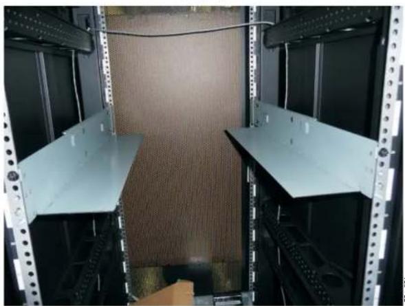
natural_image
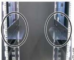
Interior view of a server rack with two metal shelving units and a textured wall (no visible text or symbols)Figure 4-11. Kit A (top picture with circles) showing rails installed. Rack Kit B is below showing the front view of this kit
natural_image
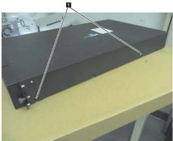
Exterior view of a black rectangular electronic device mounted on a yellow base, with no visible text or symbols.Figure4-12.2 Libraryrackanchorsandmountingbrackets
- Install the library rack anchors (2) as shown in Figure 4-12 on each side of your library using the longest counter-sunkscrews included in the ackkit.

natural_image
Completely dark image with no visible content, text, or symbols.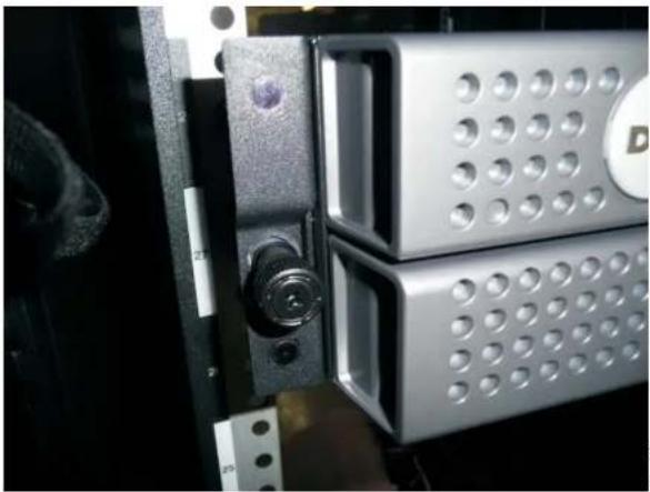
natural_image
Close-up of a metallic hard drive with circular perforations and a D-shaped label (no readable text or symbols)Figure4-14.2 Library sidescrewstoremove
-
Install the library mounting brackets (1) as shown on the 2U library on each side of the library using the screw that was removed from your library and an additional short, counter-sunkscrew included in the rack kit. (The4Urack anchors and mounting brackets are similar.)
-
With library rack anchors and mounting brackets installed, slide the library onto other rails (asshownin Figure 4-15 on page 4-14 and Figure 4-16 on page 4-14). Gently push the library into other rack to lock the REAR anchors installed one each side of the library. Whentelibrary stops, the front mounting brackets will be flush with the vertical track rails.
natural_image
Close-up of a metallic server rack with ventilation slots and a door, showing no visible text or symbols.Figure4-15.Slidingthe2Ulibraryintotherack
natural_image
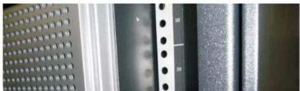
Close-up of metallic perforated panels and a textured surface with vertical holes (no text or symbols visible)ofeachmountingbracketandtighteningthem(1).
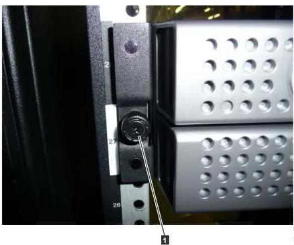
natural_image
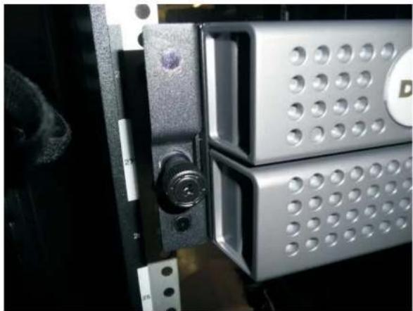
Close-up of a mechanical component with numbered parts (1, 2, 26, 27) and a central knob inserted into a slot, no visible text or symbols.Figure4-17. Securingthe2Ulibrarytotherack
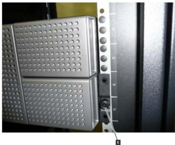
natural_image
Close-up of a metallic server rack with perforated panels and a black panel, showing a key inserted into the wall (no text or symbols visible)Figure4-18. Securingthe4Ulibrarytotherack
9.Installeithertheroundorthesquarerackholecoversforthe4Ulibraryas showninFigure4-18.Thereare6coversforeachsideforatotalof12.
AttachingtheLibrarytoaServer
The2Ulibraryandthe4Ulibrarycanbeattachedtoserversusingthefollowing
interfaces:
•SCSI(LVDUltra160)
•FibreChannel
connector.UnusedSASconnectorsdonotneedtobetermined.
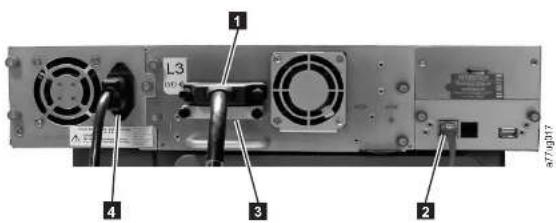
Figure4-19. AttachingaSCSIhostinterfacecabletothe2Ulibrary
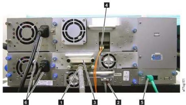
Figure 4-20. Attaching host interface cables to the 4U library. THE CONFIGURATION SHOWN IN THIS FIGURE IS USEDFOREXAMPLEONLY.THISCONFIGURATIONISNOTSUPPORTED.
deviceontheSCSIbus. Otherwise, attachoneendofaSCSICabletothe remainingportandthcotherrendtothenextdeviccontheSCSIbus.Make sure that the last device on the SCSIbus is properly terminated.
Note: Only cables and terminators specified for Ultra160 or Ultra320 use or labeled as MultiModes should be used.
Note: The hostbusadapters should be LVDSCSI. Asingle-ended (SE)SCSI hostbusadapter will work, but will severely degrade performance, and limit cable length. If therecarcany SE devices on the same SCSI bus, the entire SCSI bus will negotiate down to SE speed and severely degrade performance.
- ForaFibreChannellibrary,connectthehostinterfacecabletothehostorto aswitch.
- ForaSASlibrary, connect the Host Interface Cable to the host HBA, using a direct SFF-8088 connection, or an interposeras required. Unused SAS connectors do not need termination.
- Plug the network ethernet cable (2 in Figure 4-19 on page 4-17, 5 in Figure4-21onpage4-17, or 3 in Figure4-21onpage4-17) into the ethernet portonthecbackpanelofthelibrary. If the ethernet connection is directly attached to a serveror laptop, acrossoverethernetcable may be required.
Note: It is the customer's responsibility to supply the crossoverable if one is required.
ConnectingaPowerCord
Attention: ThisproductcanONLYbeusedwithanapprovedpowercordforyourspecificgeographicregion. Useofanunapprovedpowercordmayresultin: notmeetingindividualcountryspecificsafetyrequirements;
•overheatingwithpotentialpersonalinjuryand/orpropertydamage;and •afractureresultingintheinternalcontactsbeingexposed,whichpotentially couldsubjecttheusertoashockhazard.
Foreverypowersupplyinthelibrary,completethefollowingsteps.
3.Plugtheotherendofeachpowercordintothencarestproperlygrounded poweroutlet.Usescparatepowersourcesforeachpowersupplyforredundant power.
Attention:Todisconnectallpowerfromthelibrary,removethepowercord fromcachoutlet.Thepowerbuttonremovespowerfromportionsofthelibrary andthedrives,butthepowersuppliesstillhaveACpowerattheirinputs.
4. Removetheprotectiveplasticontheexteriorsurfacesofthelibrary
5. Turn On the library using the power button. Check the Operator Control Panel display to make sure the library is receiving power. If it is not, check the power connections and your powers source. During the Power-On Self Test (POST), all four LEDs are illuminated briefly, followed by flashing Ready LED. When the initialization sequence is complete, the Homescreen (see "Power-ON Display" on page 2) will be displayed.
ConfiguringYourLibrary
Note: Review the information in "Installation Planning" before configuring your library.
The library can be configured using the Operator Control Panel and or the Web Interface. There recommended method for configuring your library is using the WebUserInterface.
Forcompletedetailedconfigurationinformationonallofthefunctionsavailableon yourlibraryusingboththeOperatorControlPanelandtheWebUserInterface,see Chapter5,"Operations,"onpage5-1.Fordefaultlibrarysettings,see"Configure: Save/Restore"onpage5-26
ChoosingYourConfigurationMethod
If you choose the factory defaults for your library configuration, goto "Using Factory Defaults as Your Configuration."
If you choose to set the WebUser Interface for configuring your library, goto "Configuring Your Library using the WebUser Interface" on page 4-20.
| ItemDefaultSetting | |
| BarCodeLabelLength8 | |
| LibraryModeRandom | |
| AutoCleanDisabled | |
| EncryptionApplicationManagedEncryption(AME) | |
Forafullistoffactorydefaults,see"Configure:Save/Restore"onpage5-26.
ConfiguringYourLibraryusingtheWebUserInterface
ToconfigureyourlibraryusingtheWebUserInterface,completethefollowing
procedures:
- "EstablishingRemoteAccesstoYourLibrary"
- "LoggingontotheWebUserInterface" on page 4-22
- "Verifying/UpdatingFirmware" on page 4-23
- "ChoosingGeneralLibrarySettings" on page 4-24
- "ChoosingtheNumberofLogicalLibrariesforYourLibrary" on page 4-25
6."EnteringPathFailoverFeatureActivationKey"onpage4-26
7."SettingUpEncryption"onpage4-27 - "ChoosingDrive(s)Interfaceldentification/Settings" on page 4-29
- "EnteringLibraryNetworkSettings" on page 4-30
10."EnteringUserAccessInformationusingtheWebUserInterface"onpage 4-32
11."EnteringDateandTimeusingtheWebUserInterface"onpage4-33 - "Configuring Logs and Traces using the WebUser Interface" on page 4-33
- "EnteringEmailNotificationInformationusingtheWebUserInterface" on page4-34
14."ConfiguringSNMPsettings"onpage4-35
15."TestingencryptionconfigurationforLibraryManagedencryption"onpage 4-36
2.PresstheDOWNbuttontohighlightstheNetworkmenu.
3.PresstheSELECTbuttontodisplaytheNetworkscreen.
4.SelectIPSTACK, and presstheSELECTbutton to highlight the Internet
Protocolfield
a.PresstheDOWNorUPbuttontoscrollthroughtheInternetProtocol options.
b. Press the SELECT button on the desired Internet Protocol.
If you select IPv6 protocol, the Configure Network menu will include options for stateless Autoconfig and Prefix length.
•StatelessAutoconfig:
-PresstheDOWNbuttontohighlightStatelessAutoconfig.
-PresstheSELECTbuttontohighlighttheStatelessAutoconfiguration field.
-PresstheDOWNbuttontoscrollthroughtheStatelessAutoconfig options.
-PresstheSELECTbuttontoapplytheoption.
- PrefixLength:
-PresstheDOWNbuttontohighlightPrefixLength.
-PresstheSELECTbuttontohighlghtthePrefixLengthoptionfield.
-PresstheUPorDOWNbuttonstoscrollthroughthePrefixLength digits.
-PresstheSELECTbuttontoapplythePrefixLengthdigits.
- If you do not want to select DHCP as your library network setting, skip this step and proceed to the next step. If you want to select DHCP as your library network setting, complete the following steps:
a.PresstheDOWNbuttontohighlightDHCP
b.PresstheSELECTbuttontohighlighttheDHCPfield.
c.PresstheDOWNbuttontoselectON.
d.PresstheSELECTbuttontoapplyyourselection.
e.SkiptoStep7.
- Press the DOWN button to select IP Address. For IPv4 only, enter only an
d. Afterentering the digits forth elastoctet of your Net mask address, press the SELECT button to apply you entries.
- Press the DOWN button to select Gateway. For IPv4, enter only an IPv4 Gatewayaddress.ForIPv6,enteronlyanIPv6Gatewayaddress.ForIPv4&IPv6,enteraGatewayaddressforbothIPv4andIPv6.
a.PresstheSELECTbuttontohighlighttheGatewayfield.
b.PresstheUPorDOWNbuttontoselectthedigit(s)inthefirstoctetof yourlibrary'sGatewayaddress.
c. Press the SELECT button to highlight the digit(s) in the next octet of your library's Gateway address.
d. Afterentering the digits forth the last octetiny our Gateway address, press the SELECT button to apply your entries.
- PresstheDOWNbuttontoselectEthernet.
a.PresstheDOWNbuttontohighlighttheEthernetfield.
b.PresstheSELECTbuttontohighlghttheEthernetsetting.
c.PresstheDOWNbuttontoselectanewsetting.
d.PresstheSELECTbuttontoapplythenewsetting.
- PresstheDOWNbuttontohighlightSAVE.PresstheDOWNagainto highlightCANCEL..ContinuetopresstheDOWNbuttontoswitchbetween SAVEandCANCEL.
• If SAVE is highlighted, press the SELECT button to apply your new configuration. If changes were made to the Network settings, a pop-up menu will display the option to create the library or cancel thereboot. If you select CANCEL in the top op menu, you will need top power cycle the library for then network change to be applied.
- If CANCEL is highlighted, press the SELECT button to cancel all of your entries and return to the Configure menu.
LoggingontotheWebUserInterface
Tocomplete the configuration of your library using the WebUserInterface, follow the steps below.
- On your host computer, open an Internet browser.
2 Inthebrowseraddressfield.entervourlibrary'sIPAddress.
- Whentheloginscreenappears,
a.SelectadminforaUserID.
b.EntersecureforaPassword.
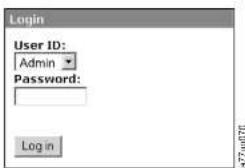
Figure4-23.LoginscreenontheWebUserInterface
Verifying/UpdatingFirmware
It is important to run the latest level of firmware. To ensure that you are running the latest level of library firmware, drive firmware, and SNMP MIB (Management Information Base) file, complete this procedure.
- Verify the SNMPMBFile currently installed on your SNMP server. Verify the levelsoflibrary and drive firmware currently installed on your library by completing the following steps:
a.ExpandMonitorLibraryintheleftnavigationpaneoftheWebUser Interface.
b.ClickLibraryIdentityandmakenotcoftheFirmwarevision.
c.ClickDriveIdentityandmakenoteoftheFirmwareRevision.
d.LogoutoftheWebUserInterface.
Note: The SNMPMIBfileisanoptionalfeature.
- Download the latest library firmware, drive firmware and SNMPMB
(ManagementInformationBase)filefromhttp://support.dell.com.
Note: The SNMPMIBfileisanoptionalfeature.
- Install the MIB file on your SNMP server. Refert to your server application documentation for instructions.
ChoosingGeneralLibrarySettings
If your library contains only one or more drive logical library, both general and specific settings will be combined into one table (see Figure 4-24 on page 4-25).
-
Expand Configure Library in the left navigation pane of the Web User Interface.
-
ClickGeneralandenterthefollowing:
•LibraryName-Enteranameforyourlibrary.
- LibraryMode(selectoneofthefollowingperlogicallibrary):
-Random:Inrandommode, the library allow stheserver's (host's) application software to select any data cartridge in any order.
-Sequential: Insequential mode, the library's firmware predefines the selection of the cartridges. After initialization, the firmware causes the library to select the first available cartridge found (counting from the I/O Station through the last slot into your library) for loading into the drive.
Important: If a Logical Library in Sequential Mode contains more than one drive, only the first drive in the Logical Library will be utilized.
-Autoload:SequentialmodewithautoloadmodeONloadsthefirst availablecartridge(slotwiththelowestnumericalvaluethatcontainsacartridge)automaticallyifthelibrarypowersONwithancemptydrive.
-Loop:SequentialmodewithloopmodeONloadsthecartridgeinthe lowestnumericalslotafterthecartridgeinthehighestnumericalslot hasbeenfilledandsentbacktoitshomeslot.Thisallowsendless backupoperationswithoutuserinteraction.
- Active Slots - Select the number of active slots you would like to assign in your library. This item will affect the number of Res. (Reserved) Slots in yourlibrary.Formoreinformationreferto"ConfiguringI/OStationsand ReservingSlots"onpage5-67.
Note: Slotscanbereservedsothattheyareinvisibletothehost.Itmaybe
-Refresh-Click this button to update the current screen.
-ApplySelections-Clickthisbuttontosubmitthechangesmadetothe screen.
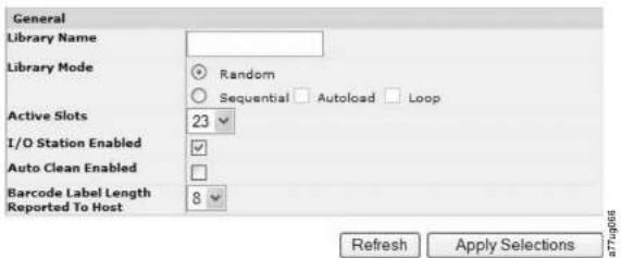
Figure4-24. The 2UlibraryConfigureLibrary: Generalscreen
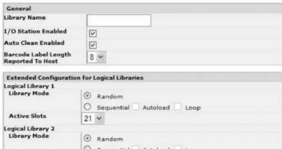
Onecartridgemagazinecannotbeassignedtotwologicallibraries.Ifyoupartition amulti-drivelibrary, cachofthemagazinesmustbeassignedtoalogicallibrary onamagazineboundary.Theentiremagazinemustbepartofonelogicallibrary only.
Note: If you have a library with two drives, you have the capability to have twological libraries.
Inafullypopulated4Ulibrarywithfourhalfheightdrivesandfourlogical libraries,resourceassignmentswillbeasfollows:
•LogicalLibrary1willcontainDrive1andthelowerleftcartridgemagazine.
•LogicalLibrary2willcontainDrive2andtheupperleftcartridgemagazine.
•LogicalLibrary3willcontainDrive3andthelowerrightcartridgemagazine.
•LogicalLibrary4willcontainDrive4andtheupperrightcartridgemagazine.
The1/OStationandslotsreservedforcleaningcartridges,ifany,aresharedamong allogicallibraries.
- Click Configure Library > Logical Libraries in the left navigation pane.

Figure4-26. The 4UlibraryConfigureLibrary:LogicalLibrariespage
- Selectthenumberoflogicallibrariesyouwouldliketocreateinyourlibrary.
3.ClickSubmittocreatethelogicallibraries.
EnteringPathFailoverFeatureActivationKey
Formoreinformation, refertothe DellPowerVaultT1.4000FailoverConfiguration Guide, included with the library documentation.
- Click Configure Library > Path Failover in the left navigation pane.
Path Failover
Feature Activation Key Path Failover is currently activated on this Tape Library.
Refresh
License enables the library failover capability. User must ensure that the Library, Host, and Backup Application are fully configured.

Figure4-28.FeatureKeyverificationscreen
Note: Follow the instructions in the DellPower Vault TL4000Failover
ConfigurationGuidetoconfigureyourenvironmentforfailover.
SettingUpEncryption
Note: ApplicationManagedEncryption(AMF) does not require a key. Library ManagedEncryption requires a license key. The customers should contact their TSR(technicalsalesrepresentative) top purchase this feature.
MinimumPrerequisitesforApplicationManagedEncryption(AME)-LTO6:
•SASandFibreChannelLTOUltrium6TapeDrive
•Ultrium6TapeCartridge
• LibraryfirmwarelevelB.50orhigher
•DrivefirmwarelevelC800orhigher,forreferencegotohttp://support.dell.com.
• TapebackupsoftwareapplicationthatsupportsLTO6encryption
MinimumPrerequisitesforApplicationManagedEncryption(AME)-LTO5:
•SASandFibreChannelLTOUltrium5TapeDrive
• Ultrium5TapeCartridge
• Libraryfirmwarelevel9.00orhigher
•DrivefirmwarelevelBBNE/BBNForhigher,forreferencegoto
http://support.dell.com
MinimumPrerequisitesforLibraryManagedEncryption(LME)-LTO5:
•SASandFibreChannelLTOUltrium5TapeDrive
•Ultrium5TapeCartridge
• Libraryfirmwarelevel9.00orhigher
•DrivefirmwarelevelBBNE/BBNForhigher,forreferencegoto
http://support.dell.com
•EncryptionKeyManagerapplication(IBMSKLM)
MinimumPrerequisitesforLibraryManagedEncryption(LME)-LTO4:
•SASandFibreChannelLTOUltrium4TapeDrive
•Ultrium4TapeCartridge
• Libraryfirmwarelevel5.80orhigher
•Drivefirmwarelevel77BEorhigher
•EncryptionKeyManagerapplication(IBMSKLM)
SettingaDrive'sMethodofEncryption
- Click Configure Library > Encryption in the left navigation panel.
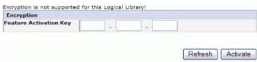
Figure4-29.FeatureActivationKeyscreen
-
On the Encryption screen, enter the Feature Activation Key to make available the librarymanagedencryptionoptions.
-
Click Activate to save the key and expand the screen for additional encryption settings.
-
Internal Label - Selective Encryption: Check your tape backup software applicationdocumentationtosceifthisfeatureissupported.
-
Internal Label - Encrypt All: Check your tape backup software application documentation to see if this feature is supported.
-
A primary and secondary key management server can be set for a logical library. Each partition has its own encryption and key management settings. Maintaining primary and secondary key management servers is desired for maximum availability of encrypted backup and recovery. These settings are required for Library Managed Encryption only. Enter the EKM Server Setting information.
Note: The IP address of the key management host must be consistent with the library Network settings. This means if the library is set to IPV4 only networks support, the key management host must be an IPV4 address. If the Dell Power Vault library is required to function in a mixed network environment the library must be set to IPv4 + IPv6.
- Primary IP address (IPv4 or IPv6): Enter the IP address of the primary key managementserver.
- Primary TCP port: After entering the Primary IP address, the library will automatically set the value of the Primary TCP port.
- Secondary IP address (IPv4 or IPv6): Enter the IP address of the secondary keymanagementserver.
- Secondary TCP port: After entering the Secondary IP address, the library will automatically set the value of the Secondary TCP port.
Note: The Default Port for TCP (SSL disabled) is 3801. The Default Port for SSLis443. These values are the default value set by the library. They can be changed depending on the user configuration but the user has to make sure they match the EKM properties file.
Note: If SSL is enabled the encryption host configuration will request a SSL port instead of TCP port. Review your IBM SKLM Knowledge Center online at http://www-01.ibm.com/support/knowledgecenter/SSWPVP/welcome?lang=enforinstructionstolocatetheappropriate port settings.
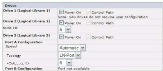
Refresh Submit
Figure4-31. TheConfigureLibrary: Drivescreen
- Select the desired settings for each drivelisted (either SCSI, SAS, or Fibre Channel). See Figure 4-31.
3.Clickoneofthefollowing:
•Refresh-toupdatethecurrentscreen
- Submit-toapply the changes made to the screen
EnteringLibraryNetworkSettings
Thispageshowsthecurrentnetworkconfigurationofthelibraryandallows modificationtotheconfiguration.Whenachangeisrequested,apop-upbox confirmstherequest.
1. Click Configure Library > Network in the left navigation pane, to display the Networkpage.
| Network | |
| Protocol Stack | Pv6 only |
| Host Name | ATL000 |
| Domain Name | string1.x.com &m.com |
| Enable SSL for Web | |
AftertheSubmitbuttonhasbeenclicked,dependingonthe changesmade,youwilleitherbedisconnectedandnecdtologin againorrebootthelibrary.
ClickingtheRefreshbuttonwillrefreshthepageandanychanges madewillnotberetained.
- Select a Protocol Stack - Choose IPv4 only, IPv6 only, or Dual Stack IPv4 & IPv6.
If you choose DualStackIPv4&IPv6, you must be prepared to enter both IPv4 and IPv6IP addresses. These sections below will group out depending on the choices made here.
3.EntertheHostName.
Note:Theunderscore(_)isnotallowedaspartofahostname.
4.EntertheDomainName.
5.DNSPrimary-EnterthelPaddressofyourprimaryDNSserver.
6.DNSSecondary-EntertheIPaddressofyoursecondaryDNSserver.
- Enable SSL for Web - If you desire to have SSL (Secure Sockets Layer) enabled, placecheckin this box.
Note: If you get a security certificate alert when logging into the Web User Interface, you can install the certificate or allow an exception (depending on the internet browsing you are using). SSL is enabled when the URI begins with https://andsomebrowserswillshowa lock.
- Ethernet Settings - Ethernet Settings choices are: Auto (the default), 10 Mbit/Half, 10 Mbit/Full, 100 Mbit/Half, 100 Mbit/Full. Please refer to http://support.dell.com?odeterminetheavailabilityofmanualEthernetsettingsinyourlibrary'shrmware.
9.EnterIPv4settings(ifapplicable).
a. Enable DHCP - Click this item ON to have the IP Address of your library automaticallysetbytheDHCPserver.
b. Static Address - Enter the assigned IPv4 address. The format of an IPv4 IP addressisa32-bitnumericaddresswrittenasfournumbersseparatedby
- Refresh-tocancelthechangesmadetothescreen.
- Submit-toapplythechangesmadetothescreen.
Note: Depending on the changes made, you will either be disconnected and need to login again, or reboot the library. If a boot is required, the following Warning message will appear after the Submit button is clicked.

Figure4-33.WarningScreen
Thelibrarymustberebootedorthechangeswillnottakeplace.
EnteringUserAccessInformationusingtheWebUserInterface
The Configure Library > User Access page is only accessible to the Admin and ServiceLogin.AccessisdeniedtoUserandSuperuserlogins.
TheAdminloginhasaccesstoalllibraryfunctionsexceptServiceLibrary> AdvanceDiagnostics.
TheServiceLoginhasaccesstoalllibraryfunctionsincludingServiceLibrary> AdvanceDiagnostics.
- Click Configure Library > User Access in the left navigation pane.
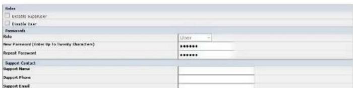
-User(ifenabled)
•Superuser(ifenabled)
•Admin
•Service
Note:OnlyonepasswordcanbesetforeachRole.
- Enter the New Password. The password has a maximum of 10 characters (A-Z, a-z,0-9,@,
, , ).
5.InRepeatPassword,enterthenewpasswordagain.
- In Support Name, enter the name of the person that will be able to offer the userhelpwiththelibrary.
Note: Only onesupportpersoncanbeconfigured for the entire tapelibrary.
Thesupportpersonmayormaynotbeoneoftheuser,superuser,or adminaccountholders.
-
In Support Phone, enter the phone number of the person that will be able to offer the user help with the library.
-
In Support Email, enter the email address of the person that will be able to offer the user help with the library.
-
Clickoneofthefollowing:
- Refresh-toupdatethecurrentscreen.
- Submit-toapplythechangesmadetothescreen.
EnteringDateandTimeusingtheWebUserInterface
- Click Configure Library > Date & Time in the left navigation pane.
Refresh Submit

Figure4-36. TheConfigureLibrary: LogsandTracesscreen
- For Error Log Mode, select Continuous so all information for logs and traces willbecaptured.
- TraceLevelandTraceFilteroptionscanbechangedbyServicepersonnelonly.
- Clickone of the following:
- Refresh - to cancel all of your entries and leave the settings as they were.
- Submit-toapplythechangesmadetothescreen.
EnteringEmailNotificationInformationusingtheWebUser Interface
ThisfunctionisnotavailableontheOperatorControlPanel.
Usethismenuitemtosetupemailnotificationoflibraryerrorsandwarnings.
- Click Configure Library > Email Notification in the left navigation pane.

Note: If you attempt to enter ablank value for the DomainName, a warning message will appear. It will say if you are using Event Notification then a value is required for the DomainName.
- Clickoneofthefollowing:
- Refresh - to cancel all of your entries and leave the settings as they were.
- Submit-toapplythechangesmadetothescreen.
ConfiguringSNMPsettings
ThispageshowsthecurrentSNMPconfigurationofthelibraryandallows modificationtotheconfiguration.Whenachangeisrequested,aboxchecksto confirmthechanges.
ClickSNMPintheletnavigationpanetodisplaytheSNMPpage.
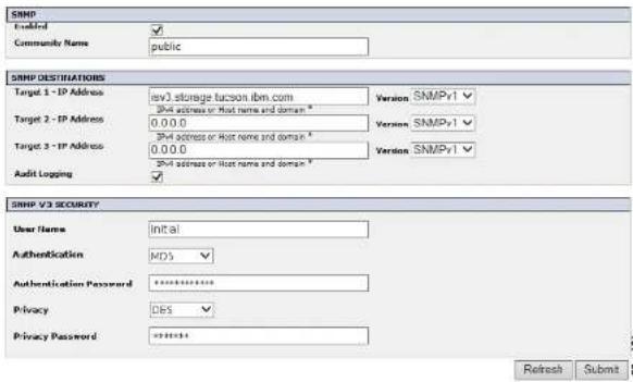
Figure4-38.ConfigureLibrary:SNMPpage
Note: For information about SNMP. see "SNMP Messaging" on page 1-7 and
- Target 3 - IP Address - Enter an optional third IP address where SNMP traps are sent, orleavcas0.0.0.0.
- Version - The library offers three versions of the SNMP protocol; v1, v2, and v3. SelectaversionforeachTargetIPaddress.
- Audit Logging - If SNMP is enabled and Audit Logging is enabled, the library sendsSNMPtrapstoanSNMPManagementconsolewhenthelibraryortape driveconfigurationchanges.
Note: This option is available only if the library firmware is 9.00 or higher, and the latest library MIB file is added to the SNMP Management console.
SNMPV3SECURITY
- User Name - Enter your preferred name, or leave as "initial".
- Authentication - The options for Authentication are none, MD5, or SHA.
- Authentication Password - The Authentication Password must be at least 8 characters in length. If Authentication is set to none, this field and the Privacy and PrivacyPasswordfieldsaredisabled.
- Privacy - The options for Privacy are none, or DES. If Privacy is set to none, then the PrivacyPasswordfielddisabled.
- Privacy Password - The Privacy Password must be at least 8 characters in length.
Note: The factory default settings for SNMPV3 Security are
- UserName-initial
•Authentication-none
•Privacy-none
TestingencryptionconfigurationforLibraryManagedencryption
Refertohttp://support.dell.com todeterminetheavailabilityofthisfeature.
If you purchased an encryption activation key and any LTO4 or higher Fibre Channelor SAS drive for your library, and the library is configured for library managed encryption, run the Key Path Diagnosticto ensure that you are encryption configuration is correct.
Important: If you click the X in the upper right corner of your internet browser window, you will not log out of the WebUser Interface.
ConfiguringYourLibraryusingtheOperatorControlPanel
If you choose to set the Operator Control Panel for configuring your library, goto "ConfigureMenu" on page 5-18 for information nonconfiguring the following items:
•LogicalLibraries
•LibrarySettings
•Drive(s)
•Network
-SetAccessPIN
- SetDateandTime
•PathFailover
To complete the configuration of your library, the following items will have to be accessed from the WebUser Interface:
•Encryption(ifpurchased)(see "ConfigureLibrary:Encryption" on page5-46)
-UserAccessInformation(see"ConfigureLibrary:UserAccess"onpage5-52)
- LogsandTraces(see"ConfigureLibrary:Logs&Traces"onpage5-54)
- EventNotificationInformation(see"ConfigureLibrary:EventNotification" on page5-55)
•KeyPathDiagnostic(ifEncryptionwaspurchased)(see"ServiceLibrary:KeyPathDiagnostics"onpage5-62)
- UpdatingFirmware(see"ServiceLibrary:UpgradeFirmware"onpage5-63)
PreparingtheHost
Followthesegeneralguidelines:
- Ensure that your backup applications supports the SCSI, SAS, or Fibre Channel host bus adapter (HBA).
- Ensure that all there required or latest available Operating System files and/or
VerifyingtheConnection
-
Depending on the server configuration, you may need to change the SCSID or FibreChannel Loop ID of the library, if the current ID does same as another device on the bus.
-
WhenthehostserverispoweredON, installthesoftwareand/ordriver(s) that arecompatiblewiththelibrary.Backupsoftwarepackagesmayrequire additionalsoftwareorlicensingtocommunicatelwiththelibraryaccessor.
-
If this is a SCSI attachment, ensure the library is properly terminated. If the library is then SCSI device, other than the SCSI host adapter on these selected SCSI bus, it must be terminated. Likewise, if the library is physically the last SCSI device, the SCSI bus, it must be terminated. Only the devices physically located at the beginning and end of the SCSI bus should be terminated.
-
Confirm that the host server operating system recognized the library. In Microsoft Windows Server 2003, you can verify this by going to: Settings > Control Panel > System > Hardware > Device Manager > Tape Drive and/or MediumChanger.
FormoreinformationonverifyingtheconnectionofSCSldevices,seethe operatingsystemdocumentation.
Cartridgemagazines
Thelibraryhasremovablemagazines.Magazineaccessispasswordprotected.For safetyreasons,theaccessormotionisstoppedwhenamagazineisremoved.
ThemagazinesarereleasedwiththeOperatorControlPanelortheWebUser Interface.IncasetheOperatorControlPanelorWebUserInterfaceinitiated processfailedorthelibrarynolongerhaspower,amanualemergencyreleaseis available.
Important:Tomanuallyreleaseamagazine,see"ReleasingtheMagazines Manually"onpage9-1.Thismanualprocessisusedonlyifthe magazinecannotbereleasedwiththeOperatorControlPanelorthe WebUserInterface.
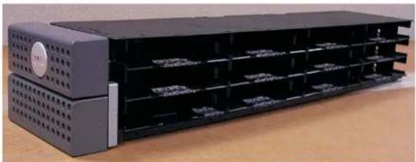
natural_image
Exterior view of a black server rack unit with ventilation grilles and drive bays (no visible text or labels)Figure4-39.2 Library left magazine
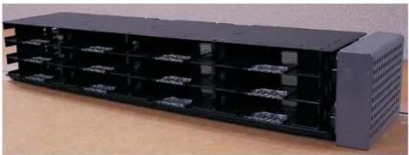
natural_image
Exterior view of a black rectangular electronic device housing with multiple internal compartments (no visible text or symbols)Figure4-40.2 Library right magazine
2ULibrary/ Ostation
TheI/O(input/output)station(seeFigure4-11onpage4-40)ina2Ulibraryis part of the left magazine. To open the I/O station, select Control > Open I/O Station.TheI/Ostationslotopens,andthe"Unlockingl/Ostation"message displays.Waitforthc"Insert/removecartridgeandclosel/Ostation"messagegeto
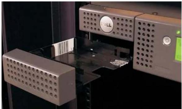
natural_image
Close-up of a 3D printer or scanner with perforated metal components and a green indicator light (no visible text or symbols)Figure4-41.2Ulibraryl/Ostationintheleftmagazine
4Ulibrarycartridgemagazines
The4Ulibraryhasfourcartridgemagazines,twooneachside(seel figure4-42and
Figure4-43onpage4-41).Theupperleftmagazinehas12storageslots. Thelower
leftmagazinehas9storageslotsandhousestheelective3-slotI/Ostation(1 in
Figure4-42].Theupperrightmagazinehas12storageslots.Thelowerright
magazinehas12storageslots.ForinformationaboutElementAddressing,see"4U
LibraryI/OSlots,StorageSlots,andDriveSlotsElementAddressesandPhysical
Locations"onpageA-2.

natural_image
Exterior view of a modern office building (no signage)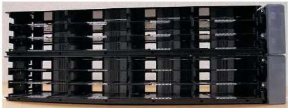
natural_image
Stacked black electronic circuit modules with visible internal components (no text or symbols)Figure4-43.4 Library right magazines
4Ulibraryl/Ostation
TheI/Ostationina4Ulibrary(see Figure 14-14)ispartofthelowerleftmagazine. To open the I/O station, select Control > Open I/O Station. The I/O station slot opens,andthe' Unlocking!/Ostation'messagedisplays.Waitforthe 'Insert/removecartridgecandclose!/Ostation'messagetoinsertorremovethe cartridge,thenclosethe!/Ostationbygentlypushingtheslotbackintotheleft magazine.
Note: It is recommended to wait for the messages before you insert or remove cartridge to ensure that the library is ready to handle the cartridges.
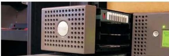
natural_image
Close-up of a metallic perforated device mounted on a control panel, with no visible text or symbols.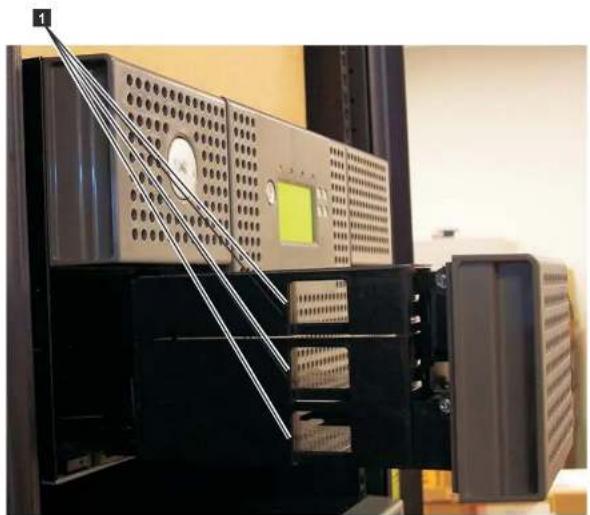
natural_image
Interior view of a server rack with ventilation grilles and a green indicator light (no visible text or symbols)Figure4-45.FingerHolesonbacksideof4Ulibraryl/Ostation
PopulatingtheLibrarywithDataCartridges
Important: Cartridges placed in the library must be labeled with the correct bar
codelabels.Foradditionalinformation,seeChapter6,"UsingUltrium
Media "onpage6"
- Put magazines back into the library. The library will automatically start up and perform an inventory check.
InsertingtheCleaningCartridge
Important:Cleaningcartridgesplacedinthelibrarymustbelabeledwiththe correctbarcodelabels.Foradditionalinformation,seeChapter6, "UsingUltriumMedia,"onpage6-1.
Note: Earlier versions of the 4 Library contained a Dedicated Cleaning Slot (DCS). This DCScan beretained and suppressed by future library firmware updates. However, library firm warclater than 3.90 will allow removal of the DCS, thus enabling this slottobe used as storages slot. Once the DCS is removed, the AutoClean cleaning cartridge slot must be configured as described below. If the DCS has been removed, it can only be reinstated by restoring factory default settings. Toremove the DCS, perform the following procedure using the Operator Control Panel (OCP): OCP->Configure->Library Settings->General->Remove DCS->No/Yes->Save.
The following criteria must be followed for AutoCleantofunction:
- Astorageslotmustbereserved(ResorRSVD).
- Reserving a slot is accomplished by reducing the Active Slot count in any particularlogicallibrary. A reserved slot (or slots) is always the last slot in the last magazine of any particularlogical library. A cleaning cartridge get thatis in a reserved slot is available to an logical library drive even if there reserved slot is not in that particularlogical library. If the library contains multiple logical libraries, typically, the last logical library is chosen to be there reserved slot containing the cleaning cartridge. As with a library with as single logical library, this slot is the last physical slot in the library (top right magazine, uppermost car slot).
- The AutoCleanfunction must be Enabled.
- Operator Control Panel: Configure->Library Settings->Auto Clean: Enabled - WebUserInterface:ConfigureLibrary->General->AutoClean Enabled->checkbox
Note:Auserhastheoptiontoperformmanualcleaningbynavigatinginthe RMU to Service > Clean Drive. In units with more than one drive to be cleaned,theusermustmanuallyrefreshthescreenafterthecleanhas completedinordertobcabletoselectanadditionaldrivctobecleaned.
- Replacethecleaningcartridge, ifneeded.
• Acleaningcartridgesmustbereplacedafter50uses. Todeterminethe numberofcleaningusesremaining, clickontheWebUserInterface, Monitor Library->Inventory.
- Click on the (+) located under that magazine presentation to expand the detailofresidentcartridges.
- CleaningcartridgesarelabeleddasCLNxxxLx. Observetheinformation displayedfortheslotscontainingacleaningcartridge. ThenumberofMedia Loadsrepresenthowmanytimesthecleaningcartridgehasbeenused. The number50, minusthatMediaLoadnumberrepresentsthenumberofuses remaining.
Chapter5. Operations
The following table lists menu navigations shortcut to activities that can be performed via the Operator Control Panel and the Web Interface.
BeforeusingtheOperatorControlPanelortheWebuserInterface, pleasereview theinformationinChapter3:UserInterfaces.
Table5-1. Menunavigationsshortcuts
| Information/Activity | MenuNavigationShortcuts | |||
| OperatorControlPanelForMoreInfoWebUserInterfaceForMoreInfo | ||||
| Accessor,number ofcartridge moves | Monitor>Library>Status>Cycles | "Monitor:Library"on page5-10 | MonitorLibrary>Library Status | "MonitorLibrary:LibraryStatus"on page5-36 |
| AutoClean, enable | Configure>LibrarySettings>AutoClean | "Configure:Library"on page5-20 | ConfigureLibrary>General | "ConfigureLibrary:General" on page5-43 |
| Cartridge, currently active/moving | Monitor>Library>Status>Act.Cart | "Monitor:Library"on page5-10 | MonitorLibrary>Library Status | "MonitorLibrary:LibraryStatus"on page5-36 |
| Cartridge, determine encryption | NotavailablewiththisinterfaceMonitorLibrary> | Inventory | "MonitorLibrary:Inventory"on page5-39 | |
| Cartridge, Inventory | Monitor>Inventory>Magazines | "Monitor:Inventory"on page5-14 | ManageLibrary>PerformInventory | "ManageLibrary:PerformInventory"on page5-42 |
| Cartridge,MoveControl | MoveCartridges"Control:MoveCartridges"on page5-17 | ManageLibrary>Move Media | "ManageLibrary:MoveMedia"on page5-41 | |
| Cartridge | Monitor>Inventory>Drive | "Monitor: | MonitorLibrary>Drive | "MonitorLibrary: |
| Dateandtime,currentsetting | Monitor>Library>Status>Date/Time |  | CurrentdateandtimedisplayedinSystemStatusscreen. |  |
| Dateandtime,set | Configure>SetDateandTime |  | ConfigureLibrary>Date&Time |  |
| DedicatedCleaningslot,removing,reinstating | Configure>LibrarySettings"Con |  | Notavailablewiththisinterface |  |
| Note: Dedicated Cleaning Slot (DCS) only available on earlier versions of the 4U library. Refer to"InsertingtheCleaningCartridge"onpage4-43. | ||||
| DHCP,currentstatus | Monitor>Library>Network>DHCP |  | ConfigureLibrary>Network |  |
| DHCP,modify | Configure > Network > DHCP |  | ConfigureLibrary>Network |  |
| Diagnostics,rundriveHeadtest | Service > Service > Drive Tests |  | Notavailablewiththisinterface | |
| Diagnostics,rundriveMediatest | Service > Service > Drive Tests |  | Notavailablewiththisinterface | |
| Diagnostics,rundriveNormalRead/Writetest | Service> Service>DriveTests"Sc |  | Notavailablewiththisinterface | |
| Diagnostics,rundrivePOST | Service > Service > Drive Tests | Notavailablewiththisinterface | ||
| Diagnostics,run | NotavailablewiththisinterfaceServiceLibrary>Key | "ServiceLibrary:1 | ||

Table5-1. Menunavigationshortcuts(continued)
| Information/Activity | MenuNavigationShortcuts | |||
| OperatorControlPanelForMoreInfoWebUserInterfaceForMoreInfo | ||||
| DisplayContrastService>DisplayContrast"Service: | Notavailablewiththis interface. | |||
| DisplayContrast"on page5-32 | ||||
| DNS,modify settings | Notavailablewiththis interface. | ConfigureLibrary>Network | "Configure Library:\Network" onpage5-50 | |
| Drive,change interface configuration | Configure>Drive>Drive Interface | "Configure: Drive"on page5-23 | ConfigureLibrary>Drives | "Configure Library:Drives" onpage5-48 |
| Drive,change SCSI/LoopID | Configure>Drive>Drive Interface | "Configure: Drive"on page5-23 | ConfigureLibrary>Drives | "Configure Library:Drives" onpage5-48 |
| Drive,cleanService>Service>Clean Drive | "Service Service (Drives)"on page5-31 | ServiceLibrary>Clean Drive | "ServiceLibrary CleanDrive"on page5-58 | |
| Drive,current SCSI/LoopID | Monitor>Drive>Identity"Monitor: | MonitorLibrary>Drive Identity | "MonitorLibrary: DriveIdentity"on page5-34 | |
| Drive,current status | Monitor>Drive>Status"Monitor: | MonitorLibrary>Drive Status | "MonitorLibrary: DriveStatus"on page5-37 | |
| Drive,data compression status | Notavailablewiththis interface. | MonitorLibrary>Drive Identity>Data Compression | "MonitorLibrary: DriveIdentity"on page5-34 | |
| Drive,Fibre,WorldwideNode Name | Monitor>Drive>Identity>Drive(n)/WWNN | "Monitor: Drive"on page5-12 | MonitorLibrary>Drive Identity | "Monitor library: DriveStatus"on page5-37 |
| Drive,Hashed SASAddress | Notavailablewiththis interface. | MonitorLibrary>Drive Status | "Monitor library: DriveStatus"on | |
| DriveDump, save | Notavailablewiththis interface. | ServiceLibrary>Save DriveDump | "ServiceLibrary: SaveDrive Dump" onpage 5-61 | |
| Encryption, activate | Notavailablewiththis interface. | ConfigureLibrary>Encryption | "Configure Library: Encryption" on page5-46 | |
| Encryption, configure | Notavailablewiththis interface. | ConfigureLibrary>Encryption | "Configure Library: Encryption" on page5-46 | |
| Encryption, testing configuration(if features available) | Notavailablewiththis interface. | ServiceLibrary>Key PathDiagnostics | "ServiceLibrary: KeyPath Diagnostics" on page5-62 | |
| Encryption, determine method,current method | Notavailablewiththis interface. | MonitorLibrary>Drive Status | "MonitorLibrary: DriveStatus" on page5-37 | |
| Ethernet settings | Monitor > Library > Network | "Monitor: Library" on page5-10 | ConfigureLibrary>Network | "Configure Library: Network" onpage5-50 |
| Email notifications:add, modify,and delete | Notavailablewiththis interface. | ConfigureLibrary>Email Notification | "Configure Library: Event Notification" on page5-55 | |
| Error log, view | Monitor > Library > Error log | "Monitor: Library" on page5-10 | ServiceLibrary>View logs | "ServiceLibrary: View Logs" on page5-59 |
|Errorlossand | NotavailablewiththisinterfaceConficientLibrariesLanes
“Configure”
Table5-1. Menunavigationshortcuts(continued)
| Information/Activity | MenuNavigationShortcuts | |||
| OperatorControlPanelForMoreInfoWebUserInterfaceForMoreInfo | ||||
| FibreChannel topology.change | Configure>Drives>Drive Interface | "Configure:Drive"onpage5-23 | ConfigureLibrary>Drives | "ConfigureLibrary:Drives"onpage5-48 |
| FibreChannel link.status | Monitor>Drive>Status>Drive(n)/Link | "Monitor:Drive"onpage5-12 | MonitorLibrary>Drive Status | "MonitorLibrary:DriveStatus"onpage5-37 |
| Firmware,drive, currentlevel | Monitor>Drive>Identity"Monitor: | "Drive"onpage5-12 | MonitorLibrary>Drive Identity | "MonitorLibrary:DriveIdentity"onpage5-34 |
| Firmware,library, identilycurrent level | Monitor>Library>Identity"Monitor: | "Library"onpage5-10 | MonitorLibrary>Library Identity | "MonitorLibrary:LibraryIdentity"onpage5-33 |
| Firmware,library ordriveupdate | Notavailablewiththis interlace. | ServiceLibrary>Upgrade Firmware | "ServiceLibrary:Upgrade Firmware"onpage5-63 | |
| Gateway,current address | Monitor>Library>Network >Gateway | "Monitor:Library"onpage5-10 | ConfigureLibrary>Network | "ConfigureLibrary:Network"onpage5-50 |
| Gateway Address,modify | Configure>Network>Gateway | "Configure:Network"onpage5-24 | ConfigureLibrary>Network | "ConfigureLibrary:Network"onpage5-50 |
| Inventory, perform | Control>Re-Inventory"Control: | "Re-Inventory"onpage5-18 | ManageLibrary>PerformInventory | "ManageLibrary:PerformInventory"onpage5-42 |
| I/OStation, configuring | Configure>LibrarySettings>I/OStation | "Configure:Library"onpage5-20 | ConfigureLibrary>General | "ConfigureLibrary:General"onpage5-43 |
| I/OStation, currentstatus | Monitor>Library>Status"Monitor: | "Library"on | SystemStatusscreen | |
| Logs,library, view | Monitor>Library>ErrorLog"Monitor:Library"on page5-10 | ServiceLibrary>View Logs | "ServiceLibrary:View Logs"on page5-59 | |
| Magazines, graphical representation | Monitor>Inventory>Magazines | "Monitor:Inventory"on page5-14 | MonitorLibrary>Inventory | "MonitorLibrary:Inventory"on page5-39 |
| Magazines, Unlock | Control>Magazines"Control: | Magazine"on page5-17 | ManageLibrary>Release Magazine | "ManageLibrary:Release Magazine"on page5-42 |
| Mode,library, change | Configure>LibrarySettings>Mode | "Configure:Library"on page5-20 | ConfigureLibrary>General | "ConfigureLibrary:General"onpage5-43 |
| Mode,library, current | Monitor>Library>Identity"Monitor: | or:Library"on page5-10 | MonitorLibrary>Library Identity | "MonitorLibrary:Library Identity"onpage5-33 |
| Netmask,current address | Monitor>Library>Network"Monitor: | or:Library"on page5-10 | ConfigureLibrary>Network | "ConfigureLibrary:Network"onpage5-50 |
| Netmask Address,modify | Configure>Network>Netmask | "Configure:Network"on page5-24 | ConfigureLibrary>Network | "ConfigureLibrary:Network"onpage5-50 |
| Network configuration, change | Configure>Network"Configure: | Network"on page5-24 | ConfigureLibrary>Network | "ConfigureLibrary:Network"onpage5-50 |
| Network configuration, view | Monitor>Library>Network"Monitor: | Monitor:Library"on page5-10 | ConfigureLibrary>Network | "ConfigureLibrary:Network"onpage5-50 |
| PathFailover, enteractivation key | Configure>ControlPath Failover | "Configure:PathFailover"onpage5-29 | ConfigureLibrary>Path Failover | "ConfigureLibrary:Path Failover"onpage |
Table5-1. Menunavigationshortcuts(continued)
| Information/Activity | MenuNavigationShortcuts | ||
| OperatorControlPanelForMoreInfoWebUserInterfaceForMoreInfo | |||
| Slots,number empty | Monitor>Library>Status"Monitor:Library"on page5-10 | SystemStatusscreen | |
| Slots,reassign numberofactive, reserving | Note:Variesaccordingtothe numberlogicallibraries.Singlepartition:Configure>LogicalLibrarySettingsMultiplepartitions:Configure>LogicalLibrarySettings>LogicalLibrary(n) | "Configure:Library"on page5-20 | ConfigureLibrary>General"ConfigureLibrary:General"onpage5-43 |
| SNMP,modify settings | Notavailablewiththis interface. | ConfigureLibrary>SNMP"ConfigureLibrary:SNMP"onpage5-56 | |
| TelnetService Port,activate | Service>TelnetServicePort"Service:TelnetService Port"onpage5-32 | Notavailablewiththis interface. | |
| Timeelapsed sincepowerON | Monitor>Library>Status"Monitor:Library"on page5-10 | MonitorLibrary>Library Status"MonitorLibrary:LibraryStatus"on page5-36 | |
| OperatorControl Panel,access PIN, enable/disable | Configure>SetAccessPIN"Configure:SetAccess PIN"onpage5-25 | Notavailablewiththis interface. | |
| WebUser Interface,user access,creator modify | Notavailablewiththis interface. | ConfigureLibrary>User Access"ConfigureLibrary:User Access"onpage5-52 | |
A. ·s A. ·s B. ·s C. ·s
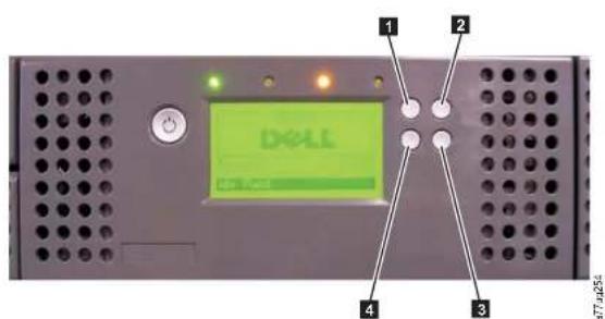
Figure5-1.2ULibraryControlKeys
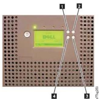
- Press the UP (1) or DOWN(4) keys to enter Interaction Mode. The Main SelectionMenuwillappear.TheMainSelectionscreenshowsMonitor,Control,Configure,andService.
- Scroll to your selection, then press the SELECT (3) key. The sub-menu for the selected menu item will appear.
- Use the UP (1) or DOWN(4) and SELECT (3) keys to scroll until you get tothearea/screenyouwishtoconfigure.
- Use the CANCEL (2) key if you wish to move backwards through the menu selections.
OperatorControlPaneIMenuTree
TheOperatorControlPanelMainmenuismadeupofthefollowingitems:
•Monitor
•Control
- Configure
•Service
The table below show each main menu item and the associated submenu items.
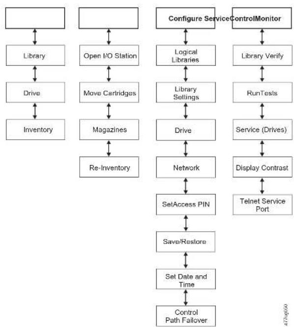
flowchart
graph TD
    A[" "] --> B["Library"]
    B --> C["Drive"]
    C --> D["Inventory"]
    E[" "] --> F["Open I/O Station"]
    F --> G["Move Cartridges"]
    G --> H["Magazines"]
    H --> I["Re-Inventory"]
    J["Configure Service"] --> K["Logical Libraries"]
    K --> L["Library Settings"]
    L --> M["Drive"]
    M --> N["Network"]
    O["ControlMonitor"] --> P["Library Verify"]
    P --> Q["RunTests"]
    Q --> R["Service (Drives)"]
    R --> S["Display Contrast"]
    S --> T["Telnet Service Port"]
    U["SetAccess PIN"] --> V["Save/Restore"]
    V --> W["Set Date and Time"]
    W --> X["Control Path Failover"]
Figure5-3. OperatorControlPanelMenuTree
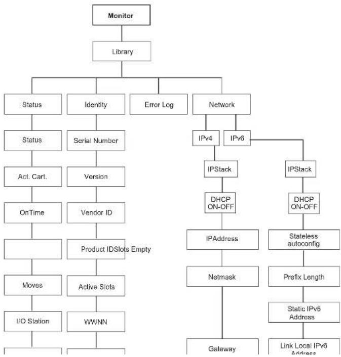
flowchart
graph TD
    A["Monitor"] --> B["Library"]
    B --> C["Status"]
    B --> D["Identity"]
    B --> E["Error Log"]
    B --> F["Network"]
    C --> G["Status"]
    C --> H["Serial Number"]
    H --> I["Act. Cart."]
    I --> J["Version"]
    J --> K["Vendor ID"]
    K --> L["OnTime"]
    L --> M["Product IDSlots Empty"]
    M --> N["Moves"]
    N --> O["Active Slots"]
    O --> P["I/O Station"]
    P --> Q["WWNN"]
    F --> R["IPv4"]
    F --> S["IPv6"]
    R --> T["IPSlack"]
    S --> U["IPSlack"]
    T --> V["DHCP ON-OFF"]
    U --> W["DHCP ON-OFF"]
    V --> X["IPAddress"]
    W --> Y["Stateless autoconfig"]
    X --> Z["Prefix Length"]
    Y --> AA["Netmask"]
    Z --> AB["Static IPv6 Address"]
    AA --> AC["Link Local IPv6 Address"]
    AB --> AD["Gateway"]
•Identity
-ErrorLog
•Network
Under Monitor > Library > Status are the following items:
•Status-Statusofthelibrary
•Act. Cart-Theserialnumberofthecartridgecurrentlyactiveinthelibrary
•OnTime-TheamountoftimethelibraryispoweredON
•SlotsEmpty-Thenumberofemptyslotsinthelibrary/totalnumberofactive slotsinthelibrary
•Moves-Thetotalnumberofcartridgemovesthatarecarriedoutbythelibrary accessor
•I/OStation-IndicateswhethertheI/Ostationisopenorclosed
•Date/Time-Givesthecurrentdateandtimethatisetinthelibrary
Under Monitor > Library > Identity are the following items.
•ServiceTag-theservicetagofthelibrary
•Version-the-currentleveloflibraryfirmwareinstalled
•VendorID-Dell
•WWNN-WorldwideNodeNameofthelibrary
•Lib.xMode-Currentlibrarymode(RandomorSequential)
Note:X=thenumberoflogicallibraries(1-4partitions).
Under Monitor > Library > Error Log, a list of errors is logged by the library. The
errorsaredisplayedbeginningwiththemostrecenterror.
Under Monitor > Library > Network are the following items:
•IPStack-InternetProtocolusedbythelibrary
•DHCP-(DynamicHostConfigurationProtocol)-recordswhetherDHCPisON
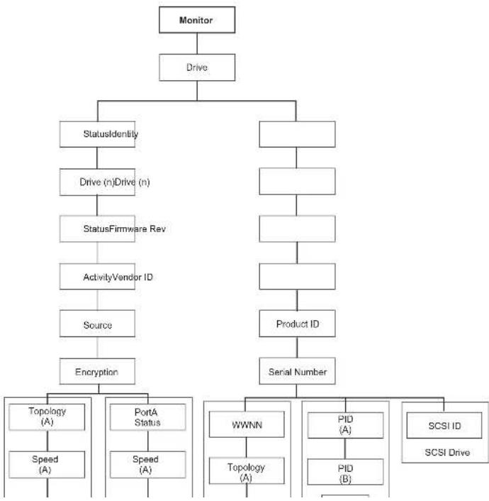
flowchart
graph TD
    A["Monitor"] --> B["Drive"]
    B --> C["StatusIdentify"]
    B --> D[" "]
    C --> E["Drive (n)Drive (n)"]
    E --> F["StatusFirmware Rev"]
    F --> G["ActivityVendor ID"]
    G --> H["Source"]
    H --> I["Encryption"]
    I --> J["Topology (A)"]
    I --> K["PortA Status"]
    I --> L["Speed (A)"]
    D --> M[" "]
    M --> N[" "]
    N --> O[" "]
    O --> P["Product ID"]
    P --> Q["Serial Number"]
    Q --> R["WWNN"]
    Q --> S["Topology (A)"]
    R --> T["PID (A)"]
    S --> U["Topology (A)"]
    T --> V["PID (B)"]
    U --> W["PID (B)"]
    X["SCSI ID\nSCSI Drive"] --> Y[" "]
UnderStatusandDrive(n) are the following items:
•Status-thecurrentstatusofthedrive
•Activity-the-currentactionbeingperformedbythedrive
•Source-theserialnumberofthecartridgecurrentlyinthedrive
- Encryption-indicatesthetypeofdataencryptioncurrentlysetfortheselected drive(willnotappearonGen3orSCSIdrives)
•Topology-thetopologychosenforafibrelibrary(see "FibreChannelInterface" onpage3-10)
•Speed-indicates the speed of the fibre channel (fibrelibrary)
•Link-indicatesthestatusofthefibrechannel(fibrelibrary)
- IHashedAddress-anaddresscalculatedfromtheWWID
UnderIdentityandDrive(n)arethefollowingitems:
•FirmwareRev-thecurrentlevelofdrivefirmware
•VendorID-Dell
•ProductID-driveinquirystring
- SerialNumber-thedriveserialnumber
- Version-Ultrium3and4halfhighSASdrivesandUltrium4FibreChannel drivesmaybelistedasVersion2.
•SCSIID-the-uniqueidentifierassignedtoaSCSIdrive
•WWNN-thefibrechanneldrive'sWorldWideNodeName
•Topology-thetopologychosenforthefibrechanneldrive
•Speed-indicates the speed of the fibre channel taped drive
•LoopID-uniqueidentifierassignedtoafibrechanneltapedrive
•PID-portidentification(SASonly)
Monitor:Inventory
Thismenuitemdisplaysthecurrentlibraryinventoryofa4Ulibrary.
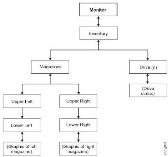
flowchart
graph TD
    A["Monitor"] --> B["Inventory"]
    B --> C["Magazines"]
    B --> D["Drive (n)"]
    C --> E["Upper Left"]
    C --> F["Upper Right"]
    D --> G["(Drive status)"]
    E --> H["Lower Left"]
    F --> I["Lower Right"]
    H --> J["(Graphic of left magazine)"]
    I --> K["(Graphic of right magazine)"]
Figure5-6.Exampleofa4UMonitor:Inventorymenu
Note:2Uhasasingleright-sidemagazine.
UnderMagazinechooseoneofthefollowingtoseeagraphicalrepresentationof thecartridgemagazine(s).Slotscontainingcartridgeswillbehhighlighted.

Note: Leftmagazineofa2ULibraryhasa1-slotI/OStation.
Theblackboxesareinventoriedcartridges.Presstheupanddownkeystoscroll. Notethatthismagazinchasa3-slotI/OStation.Theseslotscanbechangedto
storageslotsifneeded.See"ConfiguringI/OStationsandReservingSlots"on
page5-67.
PressSELECTtodisplayallemptyslotsandcartridgeserialnumbersinthe associatedmagazine.
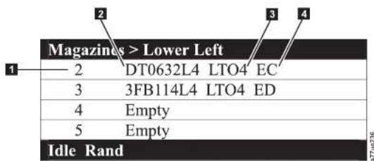
Figure5-8. Detailed information on cartridges residing in a magazine
Table5-3. Detailed information on cartridges residing in a magazine
| 1 Magazineslotnumber 3 Mediatype(generationotcartridge) | |
| 2 Cartridgevolumeserialnumberor"Empty"(meaningnocartridgcurrentlyresidinginslot) | 4 EncryptionabbreviationforLTO4cartridges:•EC-encryptioncapable(TheLTO4cartridgedoesnotcontainencrypteddata).•ED-encrypteddata(TheLTO4cartridgedoescontainencrypteddata). |
ControlMenu
The Control Monos contains the following items:
Important: Waitforthemessagesbeforeyouinsertorremovecartridgestoensure thatthelibraryisreadytohandlethecartridges. Afterthel/Ostation isclosed, you must wait forthelibrarytocompleteitsinventorybefore normallibraryoperationscommence.
Control:MoveCartridges
Usethismenuitemtomovecartridgesinthelibrary.
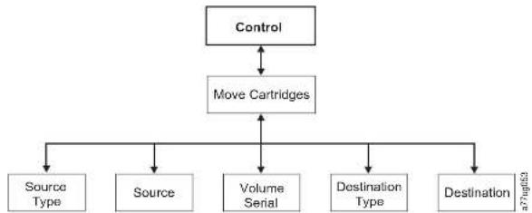
flowchart
graph TD
    A["Control"] --> B["Move Cartridges"]
    B --> C["Source Type"]
    B --> D["Source"]
    B --> E["Volume Serial"]
    B --> F["Destination Type"]
    B --> G["Destination"]
Figure5-10.Control:MoveCartridgesmenu
TomoveacartridgefrompointAtopointB,youmustmakethefollowingchoices:
- SourceType-Drive,I/Ostation,magazine.Onlythesourcetype(s)thatcontaincartridgeswillbelisted.
- Source-thechoicesstartwiththechoicemadeintheprecedingitemandthen advancesthroughallavailablechoices.
Note: If the Attention LED is on ductoasuspect cartridge, that cartridge will be identified by an exclamation point (!) when scrolling through the source cartridges.
•VolumeSerial-theserialnumberofthecartridge
- DestType-thedestinationDrive,I/Ostation,magazine
- Dest-thechoicesstartwiththechoicemadeintheprecedingitemandthen
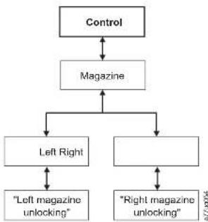
flowchart
graph TD
    A["Control"] --> B["Magazine"]
    B --> C["Left Right"]
    B --> D["Right magazine unlocking"]
    C <--> E["Left magazine unlocking"]
    D <--> F["Right magazine unlocking"]
Figure5-11. Control: Magazinemenu
Choose "Left" or "Right" tounlock the corresponding cartridge magazine(s). The magazines cannot be removed from the library by gently pulling each magazine out of the library. Toreplace magazine, insert the back of them magazine into the front of the library and gently push them magazine into the library. Them magazine will lock when inserted into the library.
Attention: Afterinserting them magazines into the library, you must wait for the library to complete its inventory before proceeding with normal library operations.
If them magazines are not pulled out of the library within 15 seconds after they are unlocked, the command will cancel and you will have to repeat the process to unlock them magazines.
Control: Re-Inventory
Usethismenuitemtoinitiateascanofthecartridgescurrentlyinthelibrary.
-SetAccessPIN
•Save/Restore
- SetDateandTime
Configure:LogicalLibraries
Usethismenuitemtoselectthenumberoflogicallibraries.TheCurrently
Configured-xsectionshowsthenumberoflogicallibrariescurrentlyconfigured.
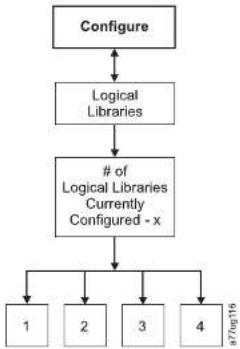
flowchart
graph TD
    A["Configure"] --> B["Logical Libraries"]
    B --> C["# of Logical Libraries Currently Configured - x"]
    C --> D["1"]
    C --> E["2"]
    C --> F["3"]
    C --> G["4"]
Figure5-13.Configure:LogicalLibrariesmenu
Note: The maximum number of Logical Libraries in a 2Uistwo.
Note: This menu is only available on libraries with multiple drives.
Note: Whenever there is a hardware configuration changes such as drives being swapped with different form factors (i.e. HH to H or F to HH), a library configuration change is needed. Reconfiguring the library by reassigning the
Configure:Library
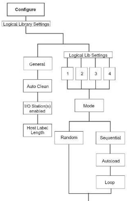
flowchart
graph TD
    A["Configure"] --> B["Logical Library Settings"]
    B --> C["General"]
    B --> D["Logical Lib Settings"]
    C --> E["Auto Clean"]
    E --> F["I/O Station(s) enabled"]
    F --> G["Host Label Length"]
    D --> H["1 2 3 4"]
    D --> I["Mode"]
    I --> J["Random"]
    I --> K["Sequential"]
    J --> L["Autoload"]
    K --> M["Loop"]
-Autoload:SequentialmodewithautoloadmodeONloadsthefirst availablecartridge(slotwiththelowcstnumericalvalucthatcontainsa cartridge)automaticallyifthelibrarypowersONwithanemptydrive.
-Loop:SequentialmodewithloopmodeONloadsthecartridgeinthe lowestnumericalslotafterthecartridgeinthehighestnumericalslothas beenfilledandsentbacktoitshomeslot.Thisallowsendlessbackup operationswithoutuserinteraction.
-StartingSequentialMode
• AutoloadOption:
- If the Autoload option is set to ON (Configure > Library Settings > Autoload), the accessor will load the first cartridge (cartridge located in the slot with the lowest numeric value) found in the storage inventory arc aintothedrive upon power ON of the library. If the library powers with a cartridge already in the drive, sequential mode will start with that cartridge unless the host issues are wind and unload command to the drive. In that case, then next cartridge sequence will be loaded into the drive.
-If the AutoloadOptioniOFF, sequentialmodemustbestarted by selecting the Move Cartridges option (Control > Move Cartridges) to load the first cartridge (or any cartridge) into the drive. Whatever cartridge is loaded into the drive, that is where these sequences start from. For example, if a cartridge from the fifth lowest numeric storage slot containing a cartridge is loaded using the Move Cartridges option, after the host tissues are wind / unload command, then next cartridge loaded will be the cartridge from then each higher numeric slot. Cartridges need not be in contiguous slots.
- LoopOption:
If the Loop option is set to ON (Configure > Library Settings >> Loop), whenthelastcartridge(cartridgeinthehighestnumericslot)is unloadedandplacedbackintostorage,theaccessorwillimmediately startoveragainloadingthefirstcartridgeintothedrive.
-StoppingSequentialMode:Tostopsequentialmode,usetheMove
Cartridges option from the Control menu (Control > Move Cartridges) to unload the drive. then next sequential cartridge will NOT be loaded. To
Note: The universal cleaning cartridge has abarcode CLNUxxLx. This cleaning cartridge is used to clean all LTO generation taps drives.
ForAutoCleantofunction, the following criterion must be met:
-On4Ulibrarieswithlibraryfirmwareof.80orlowerthatstillcontaina DedicatedCleaningSlot(DCS),or4Ulibrarieswithlibraryfirmwarehigher than1.95thatchosetoretaintheDCSintheirlibrary,aCI Ncartridgemust bepresentinthatslot.
- Onlibraricsthatdon'thavcaDCS,astorageslotmustbereserved(RSVD)by reducingtheactiveslotcountbyone.
-Acleaningcartridge(CLNxxxLx)mustbeplacedormovedtothereserved slot.
- Remove DCS - If the DCS has been removed, it cannot be reinstated. This option will no longer appear in the OperatorControlPanel.
- Host Label Length - The Host Label Length is related to the Bar Code Labels appearing on the media being used. The default value is 8, but 6 can also be chosen.
Configure:Drive
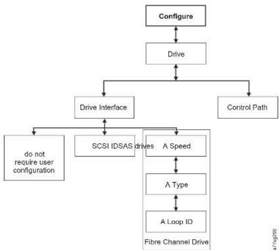
flowchart
graph TD
    A["Configure"] --> B["Drive"]
    B --> C["Drive Interface"]
    B --> D["Control Path"]
    C --> E["do not require user configuration"]
    C --> F["SCSI IDSAS drives"]
    C --> G["A Speed"]
    G --> H["A Type"]
    H <--> I["A Loop ID"]
    G --> J["Fibre Channel Drive"]
Figure5-15.Configure:Drivemenu
The following items are in this menu:
- Drive Interface - use this to assign a SCSI ID to a SCSI drive or to assign a Port Speed,PortType,andLoopIDtoaFibreChanneldrive.SASdrivesdonot requireuserconfiguration.Formoreinformationondriveinterfaces,referto "HostInterfaces" onpage3-7.
a77ug288
Configure:Network
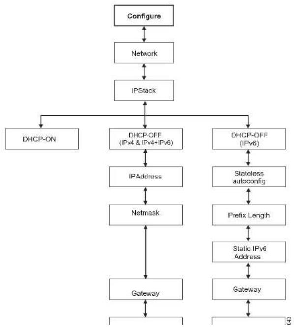
flowchart
graph TD
    A["Configure"] --> B["Network"]
    B --> C["IPStack"]
    C --> D["DHCP-ON"]
    C --> E["DHCP-OFF (IPv4 & IPv4+IPv6)"]
    C --> F["DHCP-OFF (IPv6)"]
    D --> G["IPAddress"]
    E --> H["Netmask"]
    F --> I["Stateless autoconfig"]
    F --> J["Prefix Length"]
    G --> K["Gateway"]
    H --> L["Static IPv6 Address"]
    I --> M["Gateway"]
•Netmask-theNetworkMaskaddressofthelibrary
- IPStack-theIPStackmanagesstaticIPaddresses
- Stateless autoconfig - allows IPv6 hosts to be configured automatically when connectedtoaroutedIPv6network
- Prefixlength-thelengthofthelPaddressprefix
- Static IPv6 address - a static IPv6 address that has been assigned to the library
•Gateway-theGatewayaddressofthelibrary
•Ethernet-thecurrentspeedsettingoftheethernetinterface
•DNSServer1-thefirstDNSserveraddress
•DNSServer2-thesecondDNSserveraddress
Note: If a host and domain name are centered instead of an address, the IPv4 or IPv6 address will be resolved from the DNS using that name. That address will be stored in the library rather than the name. Therefore, if the address changes, then one or an update address will have been entered.
Configure:SetAccessPIN
Usethismenuitemtoenable/disable, setorchangetheAccessPIN(personal identificationnumber) which is used to restrict access to the Control, Configure, and Servicemenus.
Note: Record the AccessPIN and store this in a secure location for future reference. Library configuration files, saved with the Save library config menu, do not include the AccessPIN.
TheOperatorControlPanel(OCP)pinisturnedoffbydefault,butisstrongly recommendedtobecanabledifyourenvironmentrequiresunitsecurity.Enabling theOCPpinfeaturepreventstheunitsettingsfrombeingtamperedwith.Users willbeallowedtoreviewthelibrarystatusandmanipulatemediawithout enteringtheOCPpin.
If a unit administrator need stomake configuration change in the unit, the OCP will ask for the 4-digit code in order to allow access stomake changes. Once all the changes are completed the inaccess will expire after 5 minutes of inactivity in the OCP's plan or configuration in the first (after time).
- PresstheSELECTbuttontohighlightthefirstdigitofthe4-digitAccessPIN.
- Use the UP and DOWN button to select each digit.
- PresstheSELECTbuttontomovetothenextdigit.
- Repeat the steps for repeating the Access PIN.
- Afterentering the final digit, press the DOWN button and select one of the following:
- Save-toapplyyoursettings.
- Cancel-todeleteyoursettings.
Note: In Figure 5-18, menus with the poundsign(#) are the only menus accessible when the AccessPIN is enabled, but entered incorrectly or before it is entered. Togain accesstoallmenus, disable the AccessPIN or enter the correct PIN number when requested.
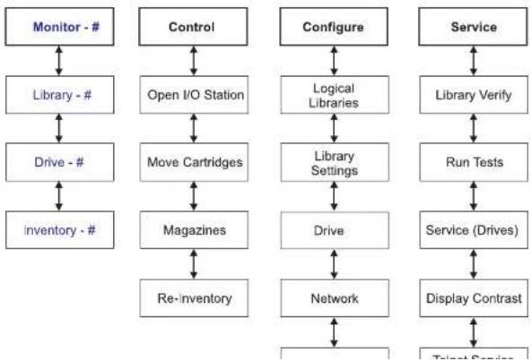
flowchart
graph TD
    A["Monitor - #"] --> B["Library - #"]
    B --> C["Drive - #"]
    C --> D["Inventory - #"]
    E["Control"] --> F["Open I/O Station"]
    F --> G["Move Cartridges"]
    G --> H["Magazines"]
    H --> I["Re-inventory"]
    J["Configure"] --> K["Logical Libraries"]
    K --> L["Library Settings"]
    L --> M["Drive"]
    M --> N["Network"]
    O["Service"] --> P["Library Verify"]
    P --> Q["Run Tests"]
    Q --> R["Service (Drives)"]
    R --> S["Display Contrast"]
    T["Talent Services"] --> U["End"]
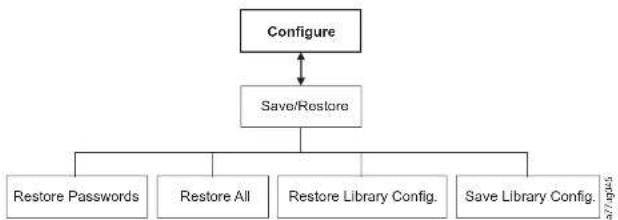
flowchart
graph TD
    A["Configure"] <--> B["Save/Restore"]
    B --> C["Restore Passwords"]
    B --> D["Restore All"]
    B --> E["Restore Library Config."]
    B --> F["Save Library Config."]
Figure5-19.Configure:Save/Restoremenu
- Restore Passwords - This menu item restores the factory default for both the RMU Adminuseraccesspasswordandtheservicepassword.
- Restore all - This menu item restores all factory default settings (refer to Table5-4).
-RestoreLibraryConfig-Thismenuitemrestoreysoursavedlibrary configurationfromaUSBdevice.Ifyouhavemorethanonesavedconfiguration file (.dbb) on your USB device, press Select, then use the up and down keys to movebetweenedifferentfiles.Whenthecorrectconfigurationfileis displayed,pressSelectagain. - Save Library Config - This menu item saves your library configuration to a USB device.
Note: Ensure the USB device is formatted for FAT12, FAT16, or FAT32 and does not use autorunfiles.
Note: Configurationfilessavedwithoneversionoflibraryfirmwaremaynotbecompatiblewithotherversionsoffirmware. Itsrecommendedtosavea configurationfileccachtimethelibrary firmwareisupgraded. Restorethe libraryusingconfigurationfilethatwassavedwiththesameversion of firmwarecurrentlyinstalledinthelibrary.
Important: Doctoring of the following functions:
Table5-4.FactoryDefaultSettings(continued)
| RestoredItemDefaultSetting*Comments | ||
| DHCPEnabledNote:DNSserveraddresses,if | available,willbeautomatically assigned.IftheDHCPserverdocs notfindanyDNSserver,theDNS fieldswillbesetto"0.0.0.0". | |
| NetworkIPModelIPv4Only | ||
| BarCodeLabelLengthReportedto Host | 8 | |
| SNMPDisabled | ||
| EmailNotificationsNone | ||
| UserAccessRestorefromOperatorControlPanel | orWebUserInterface | |
| Adminsecure(default) | ||
| LibraryModeRandom | ||
| LibraryName | (Blank) | |
| HostName | (DependsonMACAddress) | |
| Logs&TracesErrorLogMode Continuous | ||
| PathFailoverKey | Nochange LicenseKeyisprotected,if previouslycentered. | |
| OCPAccessPIN | Disabled Note:TheinitialFactoryDefault settingisdisabled.IftheOCPAccess PINsettingischanged,executing "RestoreDefaults"willnotchangethe setting. | HOCPAccessPINhasbeenabled thedefaultPINis"1234". |
| SSLforWeb | Disabled | |
| Drives | ||
| Power | PowerOn | (Alldrives) |
| Drive1SCSI-ID | 4 | SCSIDrives |
Configure:SetDateandTime
Usethismenuitemtosetthecurrentdateandtimeinyourlibrary.
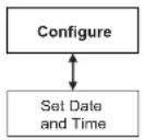
ATTU9046
Figure5-20.Configure:SetDateandTimemenu
Configure: PathFailover
UsethismenuitemtoenterthePathFailoverFeatureActivationkey(Supported on4Ulibraryonlyforlibraryfirmwarelevelsatorbelow8.xx. Supportedonboth the2Uand4Ulibrarieswithlibraryfirmwarelevelsabove8.xx).
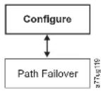
Figure5-21.Configure:PathFailover
Libraryfirmwarelevelshigherthan8.xxsupportPathFailoveronLTO5andLTO4drives.ForLTOUltrium6TapeDrivesusel.libraryfirmwareB.50orgreaterifyouwanttosupportPathFailover.Formoreinformation,refertotheDellPowerVaultTL2000/TL4000FailoverConfigurationGuide,includedwiththelibrarydocumentation.
ServiceMenu
The2U/4Ulibraryisalwaysonline,exceptforwhentheuserenterstheService Libraryarea.Awarningmessageappearsstatinethathelibraryshouldbetaken
attug047
Figure5-22. Service: Library Verifymenu
- On the Operator Control Panel, navigate to Service > Library Verify and start diagnostic.
- Push the Select key to highlight the drive field. Use the Up/Down keys to select the drive. Push the Select key to complete these selection.
- PushtheDownkeytohighlight
- PushtheSelectkeytoexecuteLibraryVerify.
-
When prompted by the Operator Control Panel display and the I/O Station opens, insert ablankorscratch data cartridge.
-
ClosetheI/OStationbypushingitbackintothelibrary.
-
While the test is running, the Operator Control Panel will display library status.
- IfthetestPASSES, resumenormallibraryoperations.
- If the test FAILS, an error codewill bed displayed. Makenote of the error,
thenrefertoChapter7,"Troubleshooting,"onpage7-1.
Note: LibraryVerifyrequiresapieceofscratchmediatoperformthetest.Once thetesthasbeeninitiated,theusermustcompletethetest.
- When prompted by the Operator Control Panel display and the I/O Station opens, remove the cartridge used in the test.
6.ClosetheI/OStationbypushingitbackintothelibrary.
- Use the Up/Down keys to highlight
. Press the Select key to exit the LibraryVerifyscreen.
Service:RunTests
Note: After running the System Test or the Slot to Slot Test, the library will need to be inventoryed. It might be required to boost the library after library diagnostics complete to ensure proper library re-detection on some backup applications.
Service:Service(Drives)
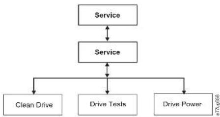
flowchart
graph TD
    A["Service"] <--> B["Service"]
    B <--> C["Clean Drive"]
    B <--> D["Drive Tests"]
    B <--> E["Drive Power"]
Figure5-24. Service: Servicemenu
The followingdrivediagnosticsandserviceproceduresareavailableinthismenu:
- Clean Drive - The accessor takes the cleaning cartridge from the dedicated cleaningcartridgeslot(DCS),orpreviouslyreservedslotifnoDCSisavailable, andinsertsitintothedrive. Afterthecleaningiscomplete,theaccessorremoves thecleaningcartridgefromthedriveandreturnsittothededicatedcleaningcartridgeslotorreservedslot.
-
Drive Tests - Power On Self Test (POST), Normal Read/Write Test, Head Test, MediaTest
-
Navigate to the desired test (Service > Service > Drive Tests).
a.Selectthedriveifmorethanoneisinstalled.
b.PresstheEnterbutton.
c.Presseither-or-totoggledrivetestoptions.
d.Movethecursortothe
changes.Whenconfigurationchangesofadisableddrivearemadefrom theWebInterface(RMU),thedrivedoesnotpowerONaftercommitting changes.
Service:DisplayContrast
Figure5-25. Service: DisplayContrastmenu
The following displaycontrastsettingsareavailableinthismenu:
- The numbers 1 through 10 will display, with 10 being the lightest shade and 1 beingthebrightest.
Service:TelnetServicePort
The TelnetServicePortmenuitemistobeusedunderthedirectionofDell TechnicalSupport.
WebUserInterfaceMenus
Note: Depending on the version of library firmware, theremaybedifferences
between the Menudescription in this document and the web user interface menus on your library.
The following menus are available on the WebUserInterface.
Table5-5.WebUserInterfaceMenus
MonitorLibrary
LibraryIdentity
DriveIdentity
Table5-5.WebUserInterfaceMenus(continued)
UserAccess
Date&Time
Logs&Traces
EmailNotification
SNMP
Save/Restore
- ServiceLibrary
CleanDrive
AdvanceDiagnostic(forServicePersonnelonly)
View Logs
ViewDriveLogs
SaveDriveDump
Perform Diagnostics
KeyPath Diagnostics (if feature is available)
UpgradeFirmware
Reboot
MonitorLibraryMenu
TheMonitorLibrarymenucontainsthefollowingsub-menuitems.
•“MonitorLibrary:LibraryIdentity”
•"MonitorLibrary:DriveIdentity"onpage5-34
•"MonitorLibrary:LibraryStatus"onpage5-36
•"MonitorLibrary:DriveStatus"onpage5-37
•"MonitorLibrary:Inventory"onpage5-39
MonitorLibrary:LibraryIdentity
Thispageprovidesaccesstothestaticinformationaboutthelibrary.Nochanges
each second of the following table 4 (which available for each national library)
Table5-6.LibraryIdentitypageelements(continued)
| MenuItemDescription2U4U | |||
| IPv6static assignedaddress | Thisisyourlibrary'sIPv6staticassignedaddress.XX | ||
| Routerdiscovery IPv6address | ThisistheIPv6routerdiscoveryaddressassignedtoyourlibrary. Note:ThermaybemorethanonclIPv6discoveryaddressifthereis morethanonelIPv6routeravailableinyournetworkenvironment. | X | X |
| MACAddressThisisthemachine'saccesscodeassignedtoyourlibrary.XX | |||
| WWidcNode Name | ThisistheWorldwideNodeNamcassignedtoyourlibrary.XX | ||
| LogicalLibraryx LibraryMode | TheExtendedLogicalLibrariesInformationtableldisplaysinformation aboutthologicallibrariescurrentlyassignedinyourlibrary.Foreach logicallibraryinyourlibrary,eitherRandomorSequentialLoop Autoloadwillbedisplayed. | X | X |
| Library Identity | |
| Serial Number | 7676024 |
| Product ID | 1973-7L |
| Currently Installed Library Firmware | A:50 / 3.18e |
| Barcode Firmware Revision | 9.80 |
| Barcode Reader | SB625 |
| IPv4 Address | 9.1.1/21.201 |
| Link local IPv4 address | FB601/2201/1FF/F14-4740 |
| IPv4 static assigned address | D002/908/6002-633-9111/211/205 |
| Router discovery IPv4 address 1 | D002/908/6002-633-2011/1FF/F14-4740 |
| Router discovery IPv4 address 2 | D002/908/6002-633-2011/1FF/F14-4740 |
| MAC Address | D00811/144740 |
| Library Mode | Random |
| WNWide Node Name | J000000E11144740 |
| Extended Logical Library Informations | |
| Logical Library 1 | |
| Library Mode | Random |
| Logical Library 2 | |
| Library Mode | Sequential Loop Autoload |
| Logical Library 3 | |
| Library Mode | Random |
| Logical Library 4 | |
| Library Mode | Sequential Loop Autoload |
Figure5-26. The4UlibraryMonitorLibrary:LibraryIdentitypage
This view is correct for a library with multiple logical partitions. The Library
Table5-7.DriveIdentitypageelements(continued)
| MenultemDescription2ULibrary4ULibrary | ||||||
| SCSIF | fibreSAS | SCSIF | fibreSAS | |||
| VersionOnlyVersion2(V2)half-highdriveswillhavea separateversionlinewiththenumber2. | X | X | X | X | ||
| Firmware Revision | Thisisthecurrentlevcloffirmwareinstalledonthe drive.Forinformationonupdatingyourfirmware,reier to"ServiceLibrary:UpgradeFirmware"onpage5-63. | X | X | X | X | X |
| SCSIID | ThisistheuniqueidentifierassignedtotheSCSIdrive toenableittoreceivecommunicationsfromthehost computer. | X | X | |||
| Element Address | Thisistheuniqueidentifierassignedtothedrivcthat allowsthehosttorecognizeandcommunicatewiththe drive. | X | X | X | X | X |
| ControlPath Drive | Ifthedrivecommunicatesallmessagesfromthchosto thelibrary,thenitisconsideredthecontrolpathdrive.Ifthedriveisthecontrolpathdrive,thiselement displays"Yes."Ifnot,thiselementdisplays No."All drivesinalogicallibrarymaybecontrolpathdrive. | X | X | X | X | X |
| Data Compression | Ifthedriveiscompressingdata,thiselementdisplays "Yes."Ifnot,thiselementdisplays No." | X | X | X | X | X |
| Interface Type | This identifies the drive host interface. | X | X | X | X | X |
| NodeName | ThisistheWorldwidenodeNameassignedtoaFibre drive. | X | X | |||
| Worldwide ID | ThisistheWorldwidelDassignedtoaSASdrive.(PortsAandB) | X | ||||
| Port A | This provides information about Port A. | X | X | |||
| PortName | ThisisthenamecassignedtoaFibrechannelportthatis "enabled". | X | X | |||
| Topology | This is the type of connection to the host. | X | X | |||
| FC-ALLoop ID | ThisistheFibreChannel-ArbitratedLoopIDofthe drive.Optionsare:L.N.LorN. | X | X | |||
| Drive Identity | 1 (LUN) |
| Vendor ID | |
| Product ID | ULT3580-HH3 |
| Serial Number | 1068000539 |
| Version | 2 |
| Firmware Revision | ACF1 |
| World Wide ID - Port A | 5000E11800245002 |
| World Wide ID - Port B | 5000E11800245003 |
| Element Address | 256 |
| Control Path Drive | Yes |
| Data Compression | Yes |
| Interface Type | SAS |
| Drive Identity | 2 |
| Vendor ID | |
| Product ID | ULT3580-HH4 |
| Serial Number | 1K10000096 |
| Firmware Revision | A23E |
| World Wide ID - Port A | 5000E11800245005 |
| World Wide ID - Port B | 5000E11800245006 |
| Element Address | 257 |
| Control Path Drive | No |
| Data Compression | Yes |
| Interface Type | SAS |
Figure5-27. The 4UlibraryMonitorLibrary: DriveIdentitypages showing one Ultrium3SAShalfheightV2drive (#1) and one Ultrium4SAShalfheightdrive (#2)
MonitorLibrary:LibraryStatus
Thispagedisplaysthedynamicinformationaboutthelibrary, such asthecurrent statusofthecomponents. Nochangescancbemadcfromthispage. Table5-8 lists allavailableaelementsontheLibraryIdentitypage. An "X" indicates that the elementdisplaysforthespecifiedlibrarytype.
Table5-8.LibraryStatuspageelements
MenuItemDescription2U4U
□ □
Table5-8.LibraryStatuspageelements(continued)
| MenultemDescription2U4U | ||
| 1.RightMagazineThisdisplayswhetherthelowerrightmagazincis"Present"or"Not Present". | X | |
| 2.LeftMagazineThisdisplayswhethertheupperleftmagazincis"Present"or"Not Present". | X | |
| 2.RightMagazineThisdisplayswhethertheupperrightmagazineis"Present"or"Not Present". | X |
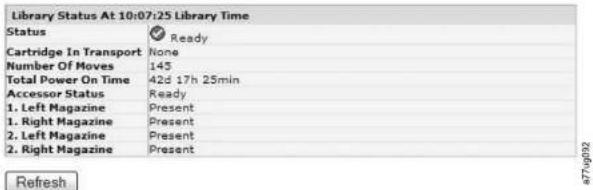
Figure5-28. The4UlibraryMonitorLibrary:LibraryStatuspage
MonitorLibrary:DriveStatus
Thispageprovidesthefollowingdetaileddynamicinformationaboutthedrivein thelibrary. Nochangescanbemadefromhere. Thedisplayedinformationvaries dependingonthelibrarymodelanddrivetype(SCSI SAS orFibreChannel).
Table5-9 lists all available elements on the Drive Status page. An "X" indicates that the element displays for the specified drivetype.
Table5-9.DriveStatuspageelements
| MenultemDescription2ULibrary4ULibrary | |||||||
| SCSIFibreSAS | SCSI | Fibre | SAS | ||||
| Status | Thestatusofthedrive.Acheckmarkindicates | X | X | X | X | X | |
X
Table5-9.DriveStatuspageelements(continued)
| MenuItemDescription2ULibrary4ULibrary | ||||||
| SCSIFibreSASSCSIFibreSAS | ||||||
| PortB Status | IndicateswhetherPortBisloggedonorout.XX | |||||
| PortName | ThenamethatisassignedtothePortonthe drive. | X | X | |||
| SpeedThespeedsettingofthedrive.ChoicesareAuto (wherethedriveautomaticallynegotiatesthe speedofthedrivetomatchthatoftheserver),1 Gb/s,2Gb/s,4Gb/s,or8Gb/sforFibre Channel;3Gb/sor6Gb/sforSAS. | X | X | X | X | ||
| Topology | Thetypeofconnectiontothehost.Thechoices areLN-port,N-port,andLport. | X | X | |||
| HashedSAS address | TheHashedSASaddressisavaluethatis calculatedfromtheWWIDforuseontheSAS interlace | X | X | |||
| FC-ALLoop ID | Thelooppositionnumber;itshowsthcnumeric ID. | X | X | |||
| Encryption Status* | Thefollowingentrieshowthecurrentencryption statusforthisdrive(method,keypath,BOP, densityrcport). | X | X | X | X | |
| Encryption method* | Thetypeofencryptionthatisenabledonthe drive. | X | X | X | X | |
| Keypath*Thepaththatisusedfortransferringan encryptionkey.Thissettingisdependentupon theencryptionmethodselected. | X | X | X | X | ||
| BOPpolicy* | IndicateswhethertheBeginningofPartition (BOP)policyisenabledordisabled.Ifencryption isenabled,thepolicytypemightdisplay dependingontheencryptionmethodused.Policy typesincludeInternallabelselect,Internallabel always,Enabled,orDisabled.Othertype designationsmightdisplayif.Advanced | X | X | X | X | |
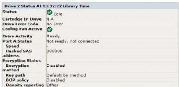
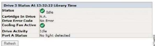
Figure5-29. The4UlibraryMonitorLibrary:DriveStatuspage
TermDefinitions:
- BOP (Beginning of Partition): BOP (Beginning of Partition) is a SCSI term, which inasinglepartitionformatisthesameasbeginningoftape.itmeansthat policyisdeterminedonwritesatLBzero.Appendingtoatape[oroverwriting atanon-zeroLB]doesnotchangethepolicyalready yinuseforthattape.
• Key Path: The avenue where key resolution is completed. This avenue is left to be determined by method (and the same), but can be set differently for some hybrid modes.
Inventory As of 14.03.04 January Time
Drive Inventory
| Drive State Label Source | |||
| 1 | Empty | ---- | |
Magazine Inventory
| 8 | 9 | 10 | 11 | + | ||
| 4 | 5 | 6 | 7 | |||
| IO-Station | 1 | 2 | 3 | |||
| 23 | 22 | 21 | 20 |
| 19 | 18 | 17 | 16 |
| 15 | 14 | 13 | 12 |
Refresh
977 u067
Figure5-30. The2UlibraryMonitorLibrary:Inventorypage

Cartridge details for 2. Left Magazine
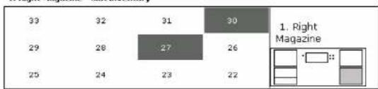
bar
| Category | Value | |---|---| | 39 | 32 | | 31 | 30 | | 29 | 28 | | 27 | 26 | | 25 | 24 | | 23 | 22 | 1. Right MagazineCartridge details for 1. Right Magazine
- Right Magazine - Slot inventory
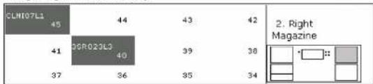
other
| Category | Value | |---|---| | CLHI07L1 | 45 | | 45 | 44 | | 43 | 43 | | 42 | 42 | | 41 | 41 | | 39 | 39 | | 38 | 38 | | 37 | 37 | | 36 | 36 | | 35 | 35 | | 34 | 34 | 2. Right MagazineCartridge details for 2. Right Magazine
| Slot # | Attn | Status | In Drive | Label | Media Loads | Comment |
| I/O Station 1 | Closed | Empty | - - - - - - - - - - - - - - - - - - - - - - - - - - - - - - - - - - - - - - - - - - - - - - - - - - - - - - - - - - - - - - - - - - - - - - - - - - - - - - - - - - - - - - - - - - - - - - - - - - - - - | |||
| I/O Station 2 | Closed | Empty | - - - - - - - - - - - - - - - - - - - - - - - - - - - - - - - - - - - - - - - - - - - | |||
| I/O Station 3 | Closed | Empty | - 31R115L4 | 6773 | Encrypted | |
| 1 | Empty | - 31R101L4 | 3505 | Encrypted | ||
| 2 | Empty | - 31R101L4 | ||||
| 3 | Empty | - 31R101L4 | ||||
| 4 | Empty | - 31R101L4 | ||||
| 5 | Full, Gen. 4 | |||||
| 6 | Full, Gen. 4 | |||||
| 7 | Full, Gen. 4 | |||||
| 8 | Empty | |||||
| 9 | Empty | |||||
a77ug049
Figure5-31. The 4 Library Monitor Library: Inventory page (Right Magazines)
Note: The4Ugraphicshowsthe5lotInventoryfortherightmagazinesofthis libraryasanexample.Theleftmagazinesaresimilar.
Managel libraryMenu
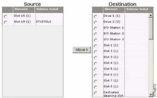
Figure5-32.ManageLibrary:MoveMediapage
The following elements appear in the Source and Destinationscreens.
Element
IntheSourcescreen, this identifies the library element that contains a cartridge. IntheDestinationscreen, this identifies the library element that is empty and can receive a cartridge.
VolumeSerial
IntheSourcescreen, thiselementdisplay theserialnumber of the cartridge. IntheDestinationscreen, thiselementcontainsnoinformation.
ManageLibrary:PerformInventory
Thispageallowsthelibrarytobere-scannedtodeterminethecurrentmedia inventory.
Perform Inventory
ConfigureLibraryMenu
TheConfigureLibrarymenucontainsthefollowingsubmenuitems:
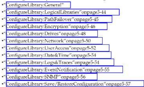
ConfigureLibrary:General
Thispageallowsyoutomakechangestogenerallibraryconfigurationelements. Aschangesaremade,theywillonlybeappliedaftertheApplySelectionsorthe Submitbuttonisslected. Aftermakingtheselection,awarningpagewillinform youoftheimpactoftheproposedchange.Insomecasesapop-upscreenwillask forconfirmation.Manychangeswillalsorequirecalibraryreboot.
Table5-10.ConfigureLibrary:Generalpageelements
| MenuItemDescription2U4U | |||
| Library Name Entered | thenameo@thelibrary.XX | ||
| I/OStation Enabled | TheI/OStationdefaultstoI/OStationEnabled.ChoosingDisabled(no checkmark)addsoncmorcstorageslottothe2ULibrary, and3more storageslotstothe4ULibrary.Whenthel/OStationisdisabled, removingoraddingmediatothelibrarymustbeperformedbyreleasing thecletstand/orrightmagazine(s). | X | X |
| AutoClean Enabled | AutoCleandedefaultstoDisabled.ForAutoCleantofunction,acleaning cartridge(CLNxxxLx)mustberesidentinareservedlibraryslotand AutoCleanmustbeperabled(turnestom) | X | X |
Table5-11.ConfigureLibrary:Specificpageelements(continued)
| MenuItemDescription2U4U | ||
| ActiveSlotsItmaybenecessarytomodifythenumberofactiveslotsstagreewiththenumberofslotsallowedbyyourhostsoftware.Tomodifythenumberofactiveslotsinyourlibrary.clickonthedropdownlistandslectthenumberofslotsyouwantactivcinyourlibrary.Also,theAutoCleanfunctionrequiresthecleaningcartridgetbeinaDCSorreservedslot.Reservedslotsarecreatedbyreducingthenumberofactiveslots. | X | X |
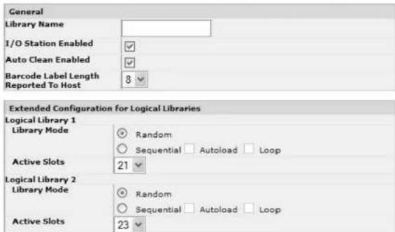
Figure5-35. The4UlibraryConfigureLibrary:GeneralandExtendedpage
ConfigureLibrary:LogicalLibraries
Topartitionyourmulti-drivelibrary,selectthenumberoflogicallibrariesyou
Note: When reducing the number of drives in your library, update the Logical Library configuration. This will remove the Attention LED on the front panel and the exclamation mark on the Iomescreen indicating that a drive is missing.
Updating the Logical Library configuration will also updated the drive element addressing and driven numbering. Replacing LTOhalfheight drives with full height drives may require you to execute Restore Factory Default to correctly update the drive element addressing and driven numbering. See "Configure Library: Save/Restore Configuration" on page 5-57.

Figure5-36. The4UlibraryConfigureLibrary:LogicalLibrariespage
ConfigureLibrary:PathFailover
ThispageallowstheusertoenterthePathFailoverfeatureactivationkey (Supported4Ulibraryonlyforlibraryfirmwarelevelsatorbelow8.xx. Supportedonboththe2Uand4Ulibrarieswithlibraryfirmwarelevelsabove8.xx) Forlibraryfirmwarelevelsbelow8.xxthePathFailoverfeatureisavailablefor select1.TO4tapedrives,andPathFailoverisnotsupportedforHalfHeight drives.LibraryfirmwarelevelshigherthanB.50supportPathFailoveronLTO6 drives.Libraryfirmwarelevelshigherthan8.xxsupportPathFailoveronLTO5 drives,aswellas1.TO4FullHeightdrives.Formoreinformation,refertotheDell PowerVaultTL4000FailoverConfigurationGuide,includedwiththelibrary documentation.

Note: Follow the instructions in the Dell PowerVault TL4000 Failover Configuration Guidetoconfigureyourenvironmentforfailover.
ConfigureLibrary:Encryption
Note:ApplicationManagedEncryption(AME)doesnotrequirealicensekey. LibraryManagedEncryptionrequiresalicensekey.ContactyourTSR (technicalsalesrepresentative)toppurchasethisfeature.
Important: The Advanced Encryption Settings are for Engineering Support use only. These field should always be set to "No Advanced Setting".
MinimumPrerequisitesforApplicationManagedEncryption(AME)-LTO6:
•SASandFibreChannelLTOUltrium6TapeDrive
•Ultrium6TapeCartridge
• LibraryfirmwarelevelB.50orhigher
•DrivefirmwarelevelC800orhigher,forreferencegotohttp://support.dell.com.
•TapebackupsoftwareapplicationthatsupportsLTO6encryption
MinimumPrerequisitesforApplicationManagedEncryption(AME)-LTO5:
•SASandFibreChannelLTOUltrium5TapeDrive
•Ultrium5TapeCartridge
•Libraryfirmwarelevel9.00orhigher
•DrivefirmwarelevelBBNE/BBNForhigher,forreferencegoto http://support.dell.com
•TapebackupsoftwareapplicationthatsupportsLTO5encryption
MinimumPrerequisitesforApplicationManagedEncryption(AME)-LTO4:
•SASandFibreChannelLTOUltrium4TapeDrive
•Ultrium4TapeCartridge
• Libraryfirmwarelevel5.80orhigher
•Drivefirmwarelevel77BEorhigher
•TapebackupsoftwareapplicationthatsupportsLTO4encryption
•SASandFibreChannelLTOUltrium4TapeDrive
• Ultrium4TapeCartridge
• Libraryfirmwarelevel5.80orhigher
•Drivefirmwarelevel77BEorhigher
•EncryptionKeyManagerapplication(IBMSKLM)
SettingorChangingaDrive'sMethodofEncryption
- Enteryourlibrary'sIPAddressinaninternetbrowseraddressfieldandpress ENTER.
- LogintotheWebUserInterface.Referto"Login"onpage2-5.
3.ExpandConfigureLibraryinthecleftnavigationpanel.
4.ClickEncryption.
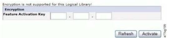
Figure5-39.FeatureActivationKeyscreen
- On the Encryption screen, enter the Feature Activation Key to enable the librarymanagedencryptionoptions.
- Click Activate to save the key and expand the screen for additional encryption settings.
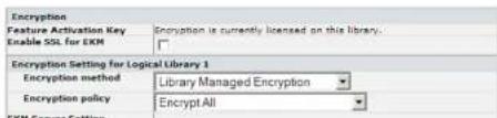
- Select Enable SSL for EKM to enable Secure Sockets Layer for the IBM SKLM application.
- Select an Encryption method, from the pull down menu, for each logical library.
- Without an encryption license key, select None or Application Managed Encryption.
- Withanencryptionlicensekey,selectLibraryManagedEncryption.
-
Select an Encryption policy, from the pull down menu, for each logical library.
-
Encrypt All: This is the default policy. It encrypts all cartridges using the defaultdatakeysspecifiedinthekeymanager.Thissettingappliestoall drivesintheTL2000/TL4000logicallibrary.
- Internal Label - Selective Encryption: Check your tape backup software applicationdocumentationtoseeifthisfeatureissupported.
-
Internal Label - Encrypt All: Check your tape backup software application documentation to see if this feature is supported.
-
A primary and secondary key management server can be set to each logical library. Each partition has its own encryption and key management settings. Maintaining primary and secondary key management servers are desired for maximum availability of encrypted backup and recovery. These settings are required for Library Managed Encryption only. Enter the EKM Server Setting information.
-
Primary IP address (IPv4 or IPv6): Enter the IP address of the primary key managementserver.
- Primary TCP port: After entering the Primary IP address, the library will automatically set the value of the Primary TCP port.
- Secondary IP address (IPv4 or IPv6): Enter the IP address of the secondary keymanagementserver.
- Secondary TCP port: After entering the Secondary IP address, the library will automatically set the value of the Secondary TCP port.
Note: The Default Port for TCP (SSL disabled) is 3801. The Default Port for SSLis443. These values are the default value set by the library.
Table5-12.DriveIdentitypageelements
| MenultemDescription2ULibrary4ULibrary | |||||||
| SCSIFibreSASSCSIFibreSAS | |||||||
| SCSIIDForeach | SCSIdrive,clickonthedropdownlistandselectthenumberoftheslotinwhichthedriveislocated. | X | X | ||||
| PowerOnForeachdrive,clickintheboxtopowerONtheselecteddrive. | X | X | X | X | X | ||
| ControlPathThecontrolpathdrivecommunicatesmessagesfromthehosttothelibrary.Selectthisoptionforeachrivethatyouwantiobeacontrolpathdrive.Atlecastonedriveincachlogicallibrarymustbedesignatedasacontrolpathdrive. | X | X | X | X | X | ||
| PortAConfiguration: | |||||||
| Speed | Thisisthecurrentspeedsettingofthedrive.ForeachFibreChanneldrive,clickonthedropdownlistandselectAutomatic,1Gb/s,2Gb/s,4Gb/s,or8Cb/s.ForeachSASdrive,selectAutomatic,3Gb/s,or6Gb/s.SelectingAutomaticwillallowlibraryspeedtoautomaticallynegotiatetothecurrentserverspeed. | X | X | ||||
| Topology | ForeachFibreChanneldrive,clickLN-Port,L.-Port,orN-Port. | X | X | ||||
| FC-ALLoopID | Thisisthelooppositionnumber.Theoptionsare:"Manual" or "Automatic". | X | X | ||||
| PortBConfiguration: | |||||||
| PortBissupportedor5ASfullheightdrivesonly.Note: PortBisonlysupportedforfailover. | X | X | |||||
X
X
Drives
Drive 1 (Logical Library 1)

Power On

Control Path
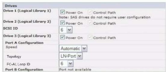
Refresh Submit
Figure5-42. TheConfigureLibrary: Drivespagefora4Ulibrary
Clickoneofthefollowing:
- Refresh-tocancelthechangesmadetothescreen.
- Submit-toapplythechangesmadetothescreen.
Note: When configuration changes of disabled drive are made from the Operator ControlPanel(OCP), the drive powers ON after committing changes. When configuration changes of disabled drive are made from the Web Interface (RMU), the driven does not power ON after committing changes.
ConfigureLibrary:Network
Thispageshowsthecurrentnetworkconfigurationofthelibraryandallows modificationtotheconfiguration.Whenachangcisrequested,apop-upbox checksconfirmstherequest.
- Click Network in the left navigation pane, to display the Network page.

AftertheSubmitbuttonhasbeenclicked,dependingonthe changesmade,youwilleitherbedisconnectedandnecdtologin againorrebootthelibrary.
ClickingtheRefreshbuttonwillrefreshthepageandanychanges madewillnotberetained.
- Select a Protocol Stack - Choose IPv4 only, IPv6 only, or Dual Stack IPv4 & IPv6.
If you choose DualStackIPv4&IPv6, you must be prepared to enter both IPv4 and IPv6IP addresses. These sections below will group out depending on the choices made here.
3.EntertheHostName.
Note:Theunderscore(_)isnotallowedaspartofahostname.
4.EntertheDomainName.
5.DNSPrimary-EnterthelPaddressofyourprimaryDNSserver.
6.DNSSecondary-EntertheIPaddressofyoursecondaryDNSserver.
- Enable SSL for Web - If you desire to have SSL (Secure Sockets Layer) enabled, placecheckin this box.
Note: If you get a security certificate alert when logging into the Web User Interface, you can install the certificate or allow an exception (depending on the internet browsing you are using). SSL is enabled when the URI begins with https://andsomebrowserswillshowa lock.
- Ethernet Settings - Ethernet Settings choices are: Auto (the default), 10 Mbit/Half, 10 Mbit/Full, 100 Mbit/Half, 100 Mbit/Full. Please refer to http://support.dell.com?odeterminetheavailabilityofmanualEthernetsettingsinyourlibrary'shrmware.
9.EnterIPv4settings(ifapplicable).
a. Enable DHCP - Click this item ON to have the IP Address of your library automaticallysetbytheDHCPserver.
b. Static Address - Enter the assigned IPv4 address. The format of an IPv4 IP addressisa32-bitnumericaddresswrittenasfournumbersseparatedby
- Refresh-tocancelthechangesmadetothescreen.
- Submit-toapplythechangesmadetothescreen.
Note: Depending on the changes made, you will either be disconnected and need to login again, or reboot the library. If a boot is required, the following Warning message will appear after the Submit button is clicked.

Figure5-44. WarningScreen
Thelibrarymustberebootedorthechangeswillnottakeplace.
ConfigureLibrary:UserAccess
Thispageallowstheusertoaddandmodifyuseraccounts.See"Login"onpage 2-5forinformationaboutusertypes.
The Configure Library > User Access page is accessible only to the Admin and ServiceLogin.AccessisdeniedtoUserandSuperuserlogins.
TheAdminloginhasaccesstoallibraryfunctionsexceptServiceLibrary> AdvanceDiagnostics.
TheServiceLoginhasaccesstoallibraryfunctionsincludingServiceLibrary> AdvanceDiagnostics.
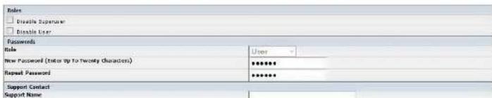
Check the Disable User check box if you do not want User to be listed on the Rolelistbox(thatis,prohibitsUserlogin).Clearthecheckboxtoallow SuperuserorUserlogin.
Passwords
- Role - The name that is associated with the chosen Access Level. Choose from User, Superuser, Admin, or Service.
Note: AdmincanselectUser, Superuser, and Adminroles. Service can select User, Superuser, Admin, and Serviceroles.
- New Password (Enter Up To Twenty Characters) - Enter a new password to be associated with the Access Level Name.
- Repeat Password - Reenter the new password for verification purposes.
SupportContact
- Support Name - The name of the individual within your company to contact for WebUserInterfaceorlibrarysupport.
Note: Only onesupportpersonisconfigured forthentiretapelibrary. The supportpersonmightormightnotbeoneoftheuser, superuser, or adminaccountholders.
- Support Phone - The phone number of the individual within your company to contactforWebUserInterfaceorlibrarysupport.
- Support Email - The email address of the individual within your company to contact for WebUserInterface or library support.
PasswordRules
- Minimum Number Of Characters - Choose the minimum password length. The factorydefaultvalueis8.Possiblerangeforthisconfigurationoptionis 8 - 2 0 . Themaximumpasswordlengthis20.
- Minimum Number Of Upper Case Alphabetic Characters (A-Z) - Choose the minimumnumberofuppercasealphabeticcharacters. Thefactorydefaultvalue is1.Possiblerangeforthisconfigurationoptionis 0 - 3 .
• Minimum Number Of Lower Case Alphabetic Characters (a-z) - Choose the
changeapassword, orarestorefactory defaultpassword from the operatorpanel (if the admin accountist the context is locked out).
•MaximumNumberOfDaysBeforePasswordMustBeChanged-Choosethe maximumnumberofdaysbeforethepasswordmustbechanged.Thefactory defaultvalueis90.Possiblerangeforthisconfigurationoptionis0-365.There isnolimitationif0isselected.
Clickone:
- Refresh-Cancelsthechangesthataremadetothescreen.
- Submit-Appliesthechangesthataremadetothescreen.
ConfigureLibrary:Date&Time
Thispageallowstheusertosethetimeanddate,andhowitwillbedisplayed.
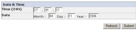
Figure5-46. TheConfigureLibrary: Date&Timepage
Time(24H)
Usinga24-hourformat,enterthecurrenthour,minutes,andseconds.
Date:Enterthecurrentmonth,day,andyear.
Clickoneofthefollowing:
- Refresh-to-cancelthechangesmadetothescreen.
- Submit-toapplythechangesmadetothescreen.
ConfigureLibrary: Logs&Traces
ThispageallowsservicepersonneltosettheerrorlogmodetoContinuousorto Stoptraceatfirsterror.
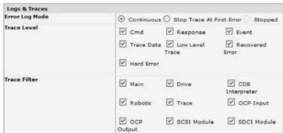
Refresh
Submit

Figure5-47.ConfigureLibrary:Logs&Tracespage
It is recommended that you select Continuous for the Error Log Mode so that all informationforlogsandtraceswillbecaptured.
Clickoneofthefollowing:
- Refresh-tocancelthechangesmadetothescreen.
- Submit-toapplythechangesmadetothescreen.
Note: The tracelevelandtracefilterselectionoptions are only changeable by Servicepersonnel.
ConfigureLibrary:EventNotification
Thispageallowstheusertoenterinformationforeventnotification.Whensetup correctly,EventNotificationallowsthelibrarytosendanemailtoadesignated individualwhenthelibraryisexperiencingaproblem.
Event Notification
Note: The TL2000/TL400emailaddressfieldcannotbeempty (clear). The email notification setup allows the user to turn off the feature by selecting the notify error and notify warnings boxes. The user can add an invalid email aslongasthemailaddressformatiscorrect(i.c.a@xxx.xxx).
SMTPServerAddress(IPv4orIPv6)
Entertheaddresssoftheemailserveroftheindividualyouwouldliketo receivetheerrorsand/orwarnings. ThiscanbeanIPv4orIPv6address, orahostnameanddomain.lfahostnameanddomainislisted,theIPv4 orIPv6addresswillberesolvedfromtheDNSusingthatname,andthe addresswillbestoredratherthanthename.lfheadresschanges, anew nameoranewaddresswillneedtobeentered.
DomainName
EntertheDomainNameforyourlibrary.Thisfieldcannotbeblankwhen usingemailnotification.
Note: If you attempt to enter ablank value for the DomainName, a warning message will appear. It will say if you are using Email Notification then a value is required for the DomainName.
Clickoneofthefollowing:
- Refresh-tocancelthechangesmadetothescreen.
- Submit-toapplythechangesmadetothescreen.
ConfigureLibrary:SNMP
ThispageshowsthecurrentSNMPconfigurationofthelibraryandallows modificationtotheconfiguration.Whenachangeisrequested,aboxchecksto confirmthechanges.
ClickSNMPintheleftnavigationpanetodisplaytheSNMPpage.

SNMP
- Enabled - Check this box to have SNMP traps sent to an SNMP Management console.
- Community Name - An SNMP community name is a text string that acts as a passwordtoauthenticatemessagesthataresentbetweentheSNMPremote managementapplicationandthelibrary. Enteryourpreferredname,orleaveas "public".
SNMPDESTINATIONS
- Target 1 - IP Address - If SNMP traps are enabled, enter an IP address where SNMPtrapsaresent.
- Target 2 - IP Address - Enter an optional second IP address where SNMP traps are sent, orleavcas0.0.0.0.
- Target 3 - IP Address - Enter an optional third IP address where SNMP traps are sent, or leave as 0.0.0.0.
- Version - The library offers three versions of the SNMP protocol; v1, v2, and v3. SelectaversionforeachTargetIPaddress.
- Audit Logging - If SNMP is enabled and Audit Logging is enabled, the library sendsSNMPtrapstoanSNMPManagementconsolewhentelibraryortape driveconfigurationchanges.
Note: This option is available only if the library firmware is 9.00 or higher, and the latest library MIB file is added to the SNMP Management console.
SNMPV3SECURITY
- User Name - Enter your preferred name, or leave as "initial".
- Authentication - The options for Authentication are none, MD5, or SHA.
- Authentication Password - The Authentication Password must be at least 8 characters in length. If Authentication is set to none, this field and the Privacy and PrivacyPasswordfieldsaredisabled.
- Privacy - The options for Privacy are none, or DES. If Privacy is set to none, then the PrivacyPasswordfielddisabled.
- Privacy Password - The Privacy Password must be at least 8 characters in
libraryusingaconfigurationfilethatwassavedwiththesameversionof firmwarecurrentlyinstalledinthelibrary.
Since the RMU can be accessed remotely, its implementation will save / restore the configuration datato / from a file on the host site. When entering commands on the OCP, the unit is accessed directly. For this reason the OCP implementation will save / restore the configuration datato / from a USB memory stick that is inserted into the USB connector on the library controller.
Note:Factorydefaultmustberestoredwhentelibrarydriveischangedfroma LTOhalfheighttofullheightconfiguration,inorderforthelibraryto correctthelementaddressinganddrivenumbering.Ifancwdriveis addedtothelibraryconfiguration,arestorefactorydefaultisnotrequired.

Figure5-50.ConfigureLibrary:Save/Restorepage
ServiceLibraryMenu
SomeServiceLibraryfunctionswillpostawarningmessagestatingthatthelibrary shouldbetakenofflinefromthehostbeforeperforminganyServicefunctions.Itis uptotheoperatortoensurethatitistakenofflincatthehost.Beforeperforming anyservicefunctions,ensurethehostisnotperforminganydatawritingor retrieval.
ServiceLibrary:CleanDrive
If the library is not configured for AutoClean, this page allows the user to manually clean the taped drive.
Adrivecleaningisinitiatedonlyafterthelibraryordrivepostedastatusmessage thatindicatesCleaningRequired

Figure5-51. NoCleaningRequired
If there is no cleaning cartridge in the library, Clean cannot be selected and the Slot#displaysN.A..See Figure 5-52

Figure5-52. Nocleaningcartridgeinlibrary
Note: If the library is configured for AutoClean, and a cleaning cartridge is residentinaries reserved slot, the library automatically loads the drivewith a cleaning cartridge. The drive completes a cleaning and the library returns the cleaning cartridge to other reserved slot. If AutoClean is enabled and a cleaning cartridge is not present in reserved slot, AutoClean status on the WebUser Interface Status screenshots of ChkMedia/RsvdSlot.

Figure5-53. ServiceLibrary: CleanDrivepage
ServiceLibrary: Advanced Diagnostics (for Service Personnel Only)
ThismenuisforusebyServicePersonnelonly.
Options > Security > Custom Level > Downloads > Automatic PromptingforfileDownloadsandFileDownloadsarebothEnabled.
•TotalNumberofEntries
•StartEntry
•NumberofEntriesperPage
•View
•ClearLog-Clearsthelogyouareviewing
•DumpLog-Dumpsthologyyouareviewing
- SaveServiceDump-CreatesaDPA(DumpAll)logoutputthatcanbeviewed orsavedtoafile
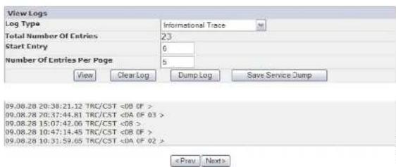
Figure5-54. ServiceLibrary: ViewLogspage
ServiceLibrary·ViewDriveLons
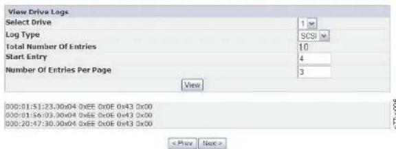
Figure5-55. ServiceLibrary: ViewDriveLogsscreen
ServiceLibrary:SaveDriveDump
Thismenuitemallowsadrivememorydumptobesavedtothehostcomputer.
-
Selectthedrive.
-
Choosetheregulardrivememorydumpoption(datathatisstoredinflash), or theforceddrivememorydumpoption(datathatisstoredinmemoryand movedtoflash).
3.ClickSaveDriveDump.
WhenSaveDriveDumpisclicked,theuserhastheoptionofsavingthedrive memorydumptotheirharddiskdrive.Theprogressstatusforthedrivememory dumpisshownontheSystemStatuscreentotherightofthemainWebUser Interfacescreen.
Note: It is recommended that both are regular and forced drivememory dumps be created and saved.
Note: Ensure that all the pop-up facilities on the web browser a reset to allow pop-up boxes to display. With Microsoft Internet Explorer, under Tools, ensure that the pop-up blocker is turned OFF and Internet Options >
ServiceLibrary:PerformDiagnostics
Note: When running the "SystemTest", the library must contain at least the same number of data cartridges, as there are carried in this library. For example, if your library has 4 drives installed, you must have formed a data cartridges in the library, prior to this start of the test. If there are carried in this library, an error message "Slot Empty" will occur, and the test will not complete successfully. The media type must be compatible with the drivetype. Otherwise, an error message "Incompatible Media" will occur and the test will fail.
Thispageprovidesthesystemadministratorwithgeneralteststoverifytheusabilityandreliabilityofthelibrary. The "SystemTest"willuseresidentdatacartridgestestetsthclothoadundunloadcapabilityofthedrives,andensurecthatthelibrarymechanicsareworkingsatisfactorily.Nodatawillbewrittentothecartridgesandthecartridgeswillbereturnedtotheirmormalslotlocation.The "SlotToSlot"testwillmoveachresidentdatacartridgefegromoneslottoanother,foreachtestcyclerequested.Whencompletingthe"SlotToSlot"test,youwillneedtoInventoryyourlibrarybeforeplacingitbackonline,sincethustestscramblesthecartridgeslotlocations.
The user select the number of test cycles before starting the test from the EXECUT E button. To cancel the test before it completes the cycles, select the STOP button.
Note: TheWebUserInterfaceSystemStatusscreenwillindicateprogressand completionoftheactivity.
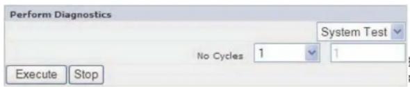
Figure5-57. ServiceLibrary: Perform Diagnosticspace
- Drive Test: The library performs a drive communication test to confirm communicationwiththedrive.
- Ethernet Test: For each key management IP address, the library performs a ping testandrecordstheresults.
- EKM Path Test: For each key management IP address that passed the ping test, the library performs a communication test.
- EKM Config Test: This test confirms that a drive is correctly configured in the keymanagertoservicekeyrequests.
ToruntheKeyPathDiagnostic,completethefollowingprocedure.
1.LogontotheWebUserInterface.Referto"Login"onpage2-5.
2.Quiescealldrives,thenunloadalldrives.
- Click Service Library, then Key Path Diagnostics.
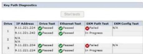
Figure5-58. ServiceLibrary: PerformKeyPath Diagnosticspage
4.ClickStartTests.
Note: If you have just enabled encryption on your library, wait for all LME drives to be displayed in the table and the Start Tests button to become active.
Eachtestwillshowaresultof"Passed" or "Failed".Ifatestfailstheremaining testswillnotbeexecuted,andthetestwillshowaresultof"N/A".TheIPAddress
-
Thelibrarycodemustbeupdatedfirst, unlessnotedotherwise. Thisaction supports any changesthatareintroduced in the librarycodeforthatdrive, or anychangesthataremadetothedriveforthatrelease.
-
These firmware updates are intended to increase overall reliability, improve tape handling, reduce the possibility of data errors, and enhanced diagnostic capabilities.
Note: Library firmware and tapedrive firmware are verified and released together. When you are updating the latest firmware, verify that all installed components such as tapedrive, and library area the latest levels noted on the Support website. Mixing different level so library and tapedrive firmware is not supported and might cause unpredictableresults.
Thispagedisplaysthecurrentlibraryanddrivefirmwareversions.Firmwareis downloadedtothehost,thenuploadedtothedriveorlibrary.
ClickBrowse...tochoose the firmware file you downloaded from the website for the library or drive you want to update. (You can update only one device at time). Besure that you choose the correct firmware for the library or drive type. ClickUpdate to initiate the file transfer and firmware update.
Note: During the update, no host drive action is possible. The drive updatetakes approximately 5 minutes. Thesystemstatuspanel (inth right of the browser window) changes from "update" to "ready".
If incompatible firmware is transferred to the library or drive the Update function terminates with message that indicates incompatible firmware. If the library has a BCR (barcodereader) that requires 9.00 or greater firmware, the Update function terminates with message that indicates the library requires firmware 9.00 or higher.
To ensure that the drive is updated with the correct firmware, referto the drive identification information provided in the Upgrade Library Firmware banner. Ensure that the drive firmware is for the correct drivetype (Full Height, Half Height), correct protocol (SCSI, SAS, Fibre Channel), and correct version (V2). Drivecode for V2 drives is not compatible with driver that are not V2.
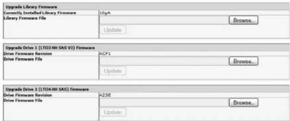
Figure5-59. TheServiceLibrary: UpgradeFirmwarepage, showing one Ultrium3SASHalfHeightV2drive and one Ultrium4SASHalfHeightdrive.
ServiceLibrary:Reboot
Important: Some options of the Web User Interface takethelibrary OFFLINE. This inactivemodecan interferewith host-based application software, causing dataloss. Ensure that the library is idle before attempting to perform any remote operation that will take the library OFFLINE.
Thispageisusedtoperformalibraryreboot.Thereisadefaulttimedelaywhen theWebUserInterfacepagerefreshesitself.Thistimeshouldbesufficientto reloadthepage.However,duringareboot,theconnectiontothelibrarymaybe lost.Iftheconnectionislost,theuserwillhavetoreloadthepagemanually.
ClicktheRebootbuttonontoinitiatethereboot.

- PullouttheI/OStationandinsertadatacartridge(s).Ona2Ulibrary,only1cartridgccanbeinsertedatatime.Onthe4Ulibrary,3cartridgescanbeinsertedatonetime.
- Closethel/OStation. Thelibrarywillautomaticallystartaninventory. The cartridgesinthel/OStationwillbecountedbutunassigneduntiltheyare movedintoslageslots.
- From the OCP Main Menu, select Control > Move Cartridges and move the datacartridgesintothedesireddataslots.See"Control:MoveCartridges"on page5-17or"ManageLibrary:MoveMedia"onpage5-41formore information.
If the library does not have an I/O Station (all slots are assigned to storage), and you wish to import media, you will need to release a magazine and insert the cartridges manually following these steps:
- From the OCP Main Menu, select Control > Magazine. Choose the desired magazinetounlock/remove.
- Pullout them magazine and insert data cartridge(s) into the empty slots.
- Pushthemagazinebackintothelibrary.Thelibrarywillautomaticallystartan inventory.
- Tomovecartridgesinthemagazinconce theyareinserted, from the OCP Main Menu, select Control > Move Cartridges and move the data cartridges into the desired slots. See "Control:MoveCartridges" on page 5-17 or "ManageLibrary:MoveMedia" on page 5-41 form more information.
Note: If your unalibrary configuration backup program, you have been added to update the backup program.
ExportMedia
Toremovecartridgesfromyourlibraryusingyourl/OStation,followthesesteps:
- From the OCP Main Menu, select Control > Move Cartridges and move the datacartridges into the I/O Station. See "Control:MoveCartridges" on page 5-17 or "ManageLibrary:MoveMedia" on page 5-41 form more information.
a. T. 1. Conn V. H. 1. a. 1. a. 1. a. 1. b. 1. b.
- Pushthemagazinebackintothelibrary. Thelibrarywillautomaticallystartan inventory.
Note: If your unalibrary configuration backup program on your host computer, use the program torunana audit of the library after cartridges have been removed to update the backup program.
ConfiguringI/OStationsandReservingSlots
2Ulibrariesusuallyhave1slotforanI/OStation,while4Ulibrarieshave3slots assignedasanI/OStation.Theseslotscanbeconfiguredasstorageifneeded.
ToconfiguretheI/OStationusingtheWebUserInterface, follow these steps.
•CotoConfigureLibrary->General.
- To enable the I/O Station, place a check mark in the I/O Station Enabled box. If it is checked as enabled, the first physical slots in the lower left magazine in 4 Uorth first physical slot in the left magazine in 2 Uis configured as an I/O station. If the I/O Station Enabled box is not checked, the slots are configured as storage.
Note: ThenumberofI/OStationslotsandstorageareaautomaticallyassigned whentheI/OStationEnabledboxischeckedorunchecked.
DedicatedCleaningSlot
Earlier versions of the 4 Library contained a Dedicated Cleaning Slot (DCS). This DC Scan beretained and dissupported by future library firmware updates. Library firmware after 1.95 will allow removal of the DCS, thus enabling this slottobe used as storage slot.
ToremovetheDCS, perform the following procedures using the OperatorControl Panel (OCP).
-
Navigate to the Library Settings (Logical Library Settings) screen Configure > LibrarySettings(orLogicalLibrarySettings.
-
SelectGeneral.
chosenforthereservedslotcontainingthecleaningcartridge.Aswithalibrary withasinglclogicallibrary,thisslotisthclastphysicalslotinthelibrary(top rightmagazine,uppermostrearslot).
Note: ConfiguretherequirednumberofreservedslotspriortoenablingAuto Clean.
Toreserveacleaningslot,followthesesteps.
•Toreserveslotsinyourlibrary.gototheWebUserInterfaceat"Choosing GeneralLibrarySettings"onpage4-24ortheOperatorControlPanelat "Configure:Library"onpage5-20togetdirectionsonreducingtheActiveslot count.
Chapter6.UsingUltriumMedia
Figure6-1 shows the LTO Ultrium Data Cartridge and its components.
1 LTOcartridgememory 4 Write-protectSwitch
2 Cartridgesoor 5 Labelarea
3 LeaderPin 6 Insertionguide
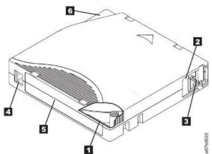
Figure6-1. The LTOUltrium Data Cartridge
Note: The same components are on all the LTOLtriumDataCartridges.
DataCartridges
The different generations of Ultrium data cartridges can be identified by color:
When processing tape in the cartridges, Ultrium Tape Drives use a linear, serpentin recording format. Then at acapacity and recording format of Ultrium data cartridges as follows:
Table6-2.CartridgeDataCapacityandRecordingFormats
| TypeNativeDataCapacityRecordingFormat | ||
| Ultrium62500GB(6250GBat2.5:1 compression) | Readsandwritesdataon2176 tracks,sixteentracksatatime | |
| Ultrium51500GB(3000GBat2:1 compression) | Readsandwritesdataon1280 tracks,sixteentracksatatime | |
| Ultrium4800GB(1600GBat2:1 compression) | Readsandwritesdataon896 tracks,sixteentracksatatime. | |
| Ultrium3400GB(800GBat2:1 compression) | Readsandwritesdataon704 tracks,sixteentracksatatime | |
| Ultrium2200GB(400GBat2:1 compression) | Readsandwritesdataon512 tracks,eighttracksatatime | |
| Ultrium1100GB(200GBat2:1 compression) | Readsandwritesdataon384 tracks,eighttracksatatime | |
The first set of tracksis written from near the beginning of the topetone near the end of the tape. The head then reposition to then next set of tracks for ther return pass. This process continues until all tracks are written and the cartridge is full, or until all data is written.
Thecartridgesdoor(2 Figure6-1onpage6-1)productsthetapefrom contaminationwhenthecartridgeisoutofthedrive. Thetapeisattacheddoa leaderpin(3 ininFigure6-1onpage6-1)behirdthedoor.Whenthecartridges insertedintothedrive,athreadingmechanismpullsthepin(andtape)outofthe cartridge,acrossthedrivehead,andontoanon-removabletake-upreel. Thehead canthenreadorwritedatafromortothetape.
Thewrite-protectswitch(4 inFigure6-1onpage6-1)preventsdatafrombeingwrittentothetapecartridge. Formoreinformation,see "Write-ProtectSwitch" on page6-6.
CartridgeCompatibility
Table6-4. Ultrium data acartridge compatibility with Ultrium taped drive
| Tape Drive | LTOUltriumDataCartridges | |||||
| 2500GB Ultrium6 | 1500GB Ultrium5 | 800GB Ultrium4 | 400GB Ultrium3 | 200GB Ultrium2 | 100GB Ultrium1 | |
| Ultrium 6 | Read/Write | Read/Write | Readonly | |||
| Ultrium 5 | Read/Write | Read/Write | Readonly | |||
| Ultrium 4 | Read/Write | Read/Write | Readonly | |||
| Ultrium 3 | Read/Write | Read/Write | Readonly | |||
| Ultrium 2 | Read/Write | Read/Write | ||||
| Ultrium 1 | Read/Write | |||||
WORM(WriteOnce,ReadMany)Cartridges
CertainrecordsretentionanddatasecurityapplicationsrequireaWriteOnce,Read Many(WORM)methodforstoringdataontape.TheLTOUltrium6,Ultrium5, andUltrium4drivesenablesWORMsupportwhenaWORMtapecartridgeis loadedintothedrive.
WORMMedia
Becausestandardread/writemediaareincompatiblewiththeWORMfeature,a speciallyformattedWORMtapecartridge(seelFigure6-2)isrequred.EachWORM cartridgehasaunique,worldwidecartridgeidentifier(WWCID),whichcomprises theuniqueCMchipserialnumberandtheuniquetapemediaserialnumber.Ultrium6WORMcartridgesaretwo-toneblackandsilvery-gray
thatlacksWORM-capablefirmwarefromwritingonaWORMtapecartridge. ForLTO6, nativedatacapacityis2500GBandcompresseddatacapacityis6250GB.
- When the drives senses a WORM cartridge, the firmware prohibits the changing or altering of user data already written on the tape. The firmware keep a track of the last appendable point on the tape.
WORMMediaErrors
The following conditions cause WORM media error to occur:
•Informationintheservomanufacturer'sword(SMW)onthetapemustmatch informationfromthecartridgememory(CM)moduleinthecartridge.Ifitdoes notmatch,amediaErrorCode7 willpostonthedrive'ssingle-characterdisplay (SCID).
- InsertingaWORMtapecartridgeeintoadrivethatisnotcompatible with WORMcausessthecartridgetobetreatedasanunsupportedmedium. Thedrive willreportamediaErrorCode7. Upgradingthedrivefirmwaretothecorrect codelevelwillresolvetheproblem.
CleaningCartridge
Witheachlibrary,aspeciallylabeledLTOUltriumCleaningCartridgeissupplied tocleanthedrivehead. Thedriveitselfdetermineswhenaheadneedstobe cleaned.Italertsyoubylightingthe"CleanDrive"(amberLED)abovethelibraryOperatorControl panel.Tocleantheheadmanually.insertacleaningcartridge into the tapeloadcompartment(see "Inserting the Cleaning Cartridge" on page
4-43). Thedrive performsthecleaningautomatically. Whenthecleaningisfinished, thedriveejectsthecartridge, andthelibraryturnsthe"CleanDrive"LEDoff. SomelibrarieshaveanAutoCleanfunctionwhich, whenenabled, willpromptthe librarytoretrievethecleaningcartridgethatresidesinthelibrary, insertitinthe drivethatneedscleaning, cleanthedrive, thenreturnthecleaningcartridgetoits homeslot.
Note: Thedrivewillautomaticallyejectanexpiredcleaningcartridge.
TheCleaningCartridgesarevalidfor50uses.
Table6-5.BarcodelabelrequirementsforUltriumtapedrivesandlibraries(continued)
| UltriumTapeDrive/LibraryBarCodeLabelRequirements | |
| 3583Required | |
| 3584Required | |
Whenreadbyalibrary'sbarcodereader,thebarcodeidentifiesthecartridge's VOLSFRthothelibrary.Thebarcodealsotellsthiblarywhetherthecartridgeisa datacartridgegeorcleaningcartridge.Inaddition,thebarcodeincludesthe two-character media-type identifier Lx, where x equals 1, 2, 3, 4, 5 or 6. L identifies thecartridgeasanLTOcartridgeandthenumberrepresentsthegenerationof cartridgeforthatcartridgesgetype. Figure6-3onpage6-6showsa samplebarcode labelforththeLTOUltrium TapeCartridge.
Tapecartridgescanbeorderedwiththelabelsincludedorwithcustomlabels.
Table6-6.CartridgesandVOLSERscompatiblewiththeUltriumTapeDrives
| CartridgesVOLSER | |
| Ultrium6DataCartridgexxxxxxL.6 | |
| Ultrium6WORMCartridgexxxxxxLW | |
| Ultrium5DataCartridgexxxxxxL5 | |
| Ultrium5WORMCartridgexxxxxxL.V | |
| Ultrium4DataCartridgexxxxxxL4 | |
| Ultrium4WORMCartridgexxxxxxLU | |
| Ultrium3DataCartridgexxxxxxL3 | |
| Ultrium3WORMCartridgexxxxxxLT | |
| Ultrium2DataCartridgexxxxxxL2 | |
| Ultrium1DataCartridge(READONLY)xxxxxxL1 | |
| LTOUltriumCleaningCartridgeCLNxxxLx | |
| *AnUltrium3TapcDrivemusthavcaminimumfirmwarelevclof54xxforittobe compatiblewiththeWORMcartridge. | |
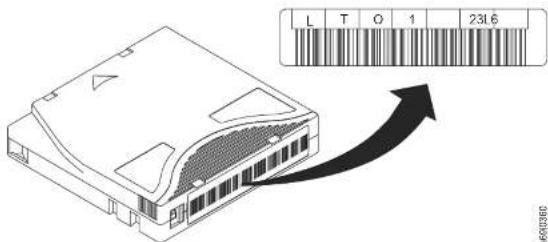
Figure 6-3. Sample bar code label on the LTO Ultrium 6 Tape Cartridge. The volume serial number (LTO123) and bar code are printedonthelabel.
GuidelinesforUsingBarCodeLabels
Apply the following guidelines whenever using barcode labels:
- Donotreusealabelorreapplyausedlabeloveranexistinglabel.
• Before you apply anew label, remove the old label by slowly pulling it at a right angle to the cartridge case.
•Usepeel-cleanlabelsthatdonotleavearesidueafterbeingremoved.Ifthereis glueresidueonthecartridge,removeitbygentlyrubbingitwithyourfinger. Donotuscasharpobject,water,orachemicaltocleanthelabelcarca.
- Examinethelabelbeforeapplyingittothecartridge.Donotusethelabelifithasvoidsorsmearsintheprintedcharactersorbarcode(alibrary'sinventoryoperationwilltakemuchlongerifthebarcodelabelisnotreadable).
- Removethelabelfromthelabelsheetcarefully.Donotstretchthelabelorcause theedgestocurl.
- Position the label within the recessed label area (see 5 in Figure 6-1 on page 6-1).
- Withlightfingerpressure,smooththelabelsothatnowrinklesorbubblesexist
tobecomeascratch(blank)datacartridge.Donotwrite-protectscratch(blank) cartridges;thetapedrivewillnotbeabletowritenewdatatothem.
If you must manually set the write-protect switch, slide it left right to the desired position.
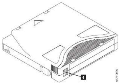
natural_image
Isometric technical drawing of a computer drive casing with labeled component (no text or symbols beyond label)Figure6-4. Setting the write-protect switch
Table6-7. Location of the write-protect switch
1 Write-ProtectSwitch
HandlingtheCartridges
Attention: Donotinsertadamagedtapecartridgeintothedrive. Adamaged cartridgecaninterfrewiththereliabilityofadriveandmayvoidthewarranties ofthedriveandthecartridge. Beforeinsertingatapecartridge, inspect the cartridgecase,cartridgedoor,andwrite-protectswitchforbreaks.
Incorinthandlinosynincarnotironmontandamnacstridaceothair
EnsureProperPackaging
- Whenshippingacartridge, use the original or better packaging.
•Alwayshiporstoreacartridgeinajewelcase. - Useonlyarecommendedshippingcontainerthatsecurelyholdsthecartridgein itsjewelcaseduringtransportation.
- Nevershipacartridgeinacommercialshippingenvelope. Alwaysplaceitina boxorpackage.
- If you ship the cartridge in a cardboard box or a box of a fourth material, ensure the following:
-Placethecartridgeinpolyethyleneplasticwraporbagstoprotectitfrom dust,moisture,andothercontaminants.
-Packthecartridgesnugly;donotallowittomovearound.
-Double-boxthecartridge(placeitinsideabox,thenplacethatboxinsidethe shippingbox)andaddpaddingbetweenthetwoboxes(seeFigure6-5).
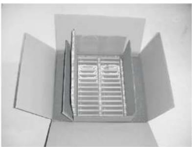
natural_image
Open cardboard box with a grating inside, viewed from above (no text or symbols visible)Figure6-5. Double-boxingtapecartridgesforshipping
Provide Drones/Acclimation and Environmental Conditions
PerformaThoroughInspection
Afterpurchasingacartridgeandbeforeusingit,performthefollowingsteps:
•Inspectthecartridge'spackagingtodeterminepotentialroughhandling.
- When inspecting acartridge, open only the cartridgedoor. Donotopen any other part of the cartridge case. The upper and lower part of the case are held together with screws; separating them destroys the usefulness of the cartridge.
•Inspectthecartridgefordamagebeforeusingorstoringit.
- Inspecttherearofthecartridge(theparthatloadsfirstintothetapeload compartment)andensurethattherearenogapsintheseamofthecartridge case.Iftherearegapsintheseam(seeFigure 6-6),theleaderpinmaybe dislodged.
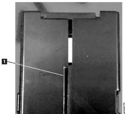
natural_image
Close-up of a metallic mechanical component with two vertical slots and a flat top (no visible text or symbols)Figure6-6. Checking forgapsin these amsolacartridge
EnvironmentalandShippingSpecificationsforTapeCartridges
Beforeyouuseatapecartridge,acclimateittotheoperatingenvironmentfor24 hoursorthetimenecessarytopreventcondensationinthedrive(thetimewill vary,dependingontheenvironmentalextremestowwhichthecartridgewas exposed).
The best storage container for the cartridges (until they are opened) is the original shipping container. The plastic wrapping prevents dirt from accumulating on the cartridges and partially protect them from humidity changes.
Whenyoushipacartridge, placeitinitsjewelcaseorinasealed, moisture-proof bagtoprotectitfrommoisture, contaminants, and physicaldamage. Ship the cartridgeinashippingcontainerthathasenoughpackingmaterialtocushionthe cartridgeandpreventitfrommovingwithinthecontainer.
Table6-8 gives the environment for operating, storing, and shipping LTOUltrium Tape Cartridges.
Table6-8.Environmentforoperating,storing,andshippingtheLTOUltriumTapeCartridge
| EnvironmentalSpecifications | ||||
| EnvironmentalFactorOperatingOperationalStorage | ArchivalStorage ^2 | Shipping | ||
| Temperature | 10to45°C(50to113°F) | 16to32°C(61to90°F)16to | 25°C(61to77°F) | -23to49°C(-9to120°F) |
| Relativehumidity(non-condensing) | 10to80%20to80% | 20to50%5to80% | ||
| Maximumwetbulb temperature | 26°C(79°F) | 26°C(79°F) | 26°C(79°F) | 26°C(79°F) |
| Note:1. The short term or operational storage environment is for storage durations of up to six months.2. The long term or archival storage environment is for durations of six months up to ten years. | ||||
Chapter7.Troubleshooting
•The library consists of the following CRUs(CustomerReplaceable Units):
-ControlCard(electronics,processor,memory,etc.)
-PowerSupply
-DriveSled(driveplusdrive-to-libraryconnectivity)
-CartridgeMagazines
•ServiceSpare:
-LibraryEnclosure(accessor,Operatorcontrolpaneldisplay,etc.)
•OtherpossibleReplacementPartsare:
-DataCartridges
-Cables/Terminator
Important: Before replacing any CRU and after finding the problem and
performinganylistedactionslistedintheTroubleshootingTablebelow,
besuretoreviewthe"ProceduresforIsolatingCRUProblems"on
page7-7tohelpconfirmthefailingCRU.
The following tableistestartingpointforallserviceissues.Findthereason whichclosestresemblestheproblemyouareexperiencingandperformthelisted action. If you are unabletocorrect the problem, create a prioritized list of replacement parts required. Selectonlyone CRU at timestarting with themost likely based on the "1" procedures for isolating CRU problems "on page 7-and/or the error code listing.
Aftercorrecting the problem, run Library Verify (OperatorControlPanel: Service >
LibraryVerify)toensurethatallibrarycomponentsarefunctioningproperly
beforeresumingnormallibraryoperations.
Table7-1.Troubleshootingtable
| ProblemSolution | |
| INSTALLATION/CONFIGURATION | |
| ENCRYPTION | |
| EncryptionError:Displayedwhenthedrivedetectsancerrorassociatedwithanencryptionoperation-iftheprolomeoccurredwhilethetapedrivewaswritingdatato,orreadingdatafrom,tape | 1.Checkthehostapplicationtoensurethekeymanagementapplicationisprovidingthecorrectencyoptionkey.Refertothe"DriveSenseData"onpageC-7returnesforanencryptionoperation.Retrytheencryptionoperationalfterthekeymanagementapplicationproblemshavebecnresolved.2.Checktheoperationofthetapedrivebyresettingthedrive(OperatorControlPanel:Service>Service>DrivePower)andrunningPOST.RefertothecrorcodedisplayedonthcOperatorControlPanclithedriveresetsandPOSTfails.RetrytheencryptionoperationifthedriveresetandPOSTcompletewithouterrors.3.Checkthemedia.Ensurethecorrectmediaisbeingused.DataencryptionissupportedwithLTOUltrium4.5,and6DataandWORMCartridgesonly.Retrytheencryptionoperationwiththetapecartridgeinanotherencryptionenableddrive.Replacethemediaiftheproblmrepeatswiththesamctapcartridgeinmultipledrives.IftheproblemoccurredwhilethetapedrivewasrunningPOSTordiagnostics,replacethedrive.Theerrorcodeclearswiththefirstst attemptedwrite/readaftertheencryptionkeyischanged,orwhenthedriveisplacedinmaintencemode. |
| Encryption-relatederrorisposted | ChecktheIBMSKLMapplication/serrorlogs,devicedriverlogs,tapelibraryerrorlogs,andtapedriveerrorlogslorentriesthalarerelatedtoencryption.See"ServiceLibraryViewLogs"onpage5-59,"ServiceLibrary:ViewDriveLogs"onpage5-60,chapter8,"Errorcodes,"onpage8-1,and"DriveSenseData"onpageC-7. |
| ConnectionproblemwiththeIBMSKLMapplication | Ifyouareusinglibrary-managedencryption,performtheKeyPathDiagnostic(sce:ServiceLibrary:KeyPathDiagnostics"onpage5-62)ifthiscaturecisavailable.Ifthetestiffs,aproblemcouldexistwiththeIPaddress,theethernetcable,orthekeymanagementserver.Performmthefollowing:1.ChecktheEthernetconnectionbetweenthelibraryandthckcymanagementserver |
| FRONTPANELLEDs | |
| AttentionLEDTodeterminewhythe | AttentionLEDisturnedON,logintotheWebUserInterface and select Service Library > View Logs > Warning Trace.DriveSledIssues:•Referto"IsIatingDriveSledProblems"onpage7-9.•Wheneverthereisahardwareconfigurationchangesuchasdrivesbeing swappedwithdifferentformfactors(i.c.III ltoFI lorFI ltoIII ),alibrary configurationchangeisneeded.Reconfiguringthelibrarybyreassigning the amountoflogicallibrarieswillclearthisissue.NavigatetotheWebUser Interface Configure Library > Logical Libraries or to the Operator Control Panel's Configure > Logical Libraries section and reassign the logical libraries. Ifyoudonotwanttochangeyourlogicallibraryconfiguration,resubmityour currentsettings.•Restore factory defaults (Operator Control Panel: Configure > Save/Restore and select Restore All, or Web User Interface: Configure Library > Save/Restore andselectRestore).MedialIssues:•Avoidcontaminationbyensuringthatthelibraryisinstalledinaclean, contamination-freeenvironment.Continuedcleaningthetapeddriveasneeded.Referto"ChoosingaLocation"onpage4-1.•Acartridgeshouldbcacclimatedforatcast24hoursbeforcbeigused, particularlyifithasbeenstoredatasubstantiallydifferenttemperatureorlevel ofhumiditythanthelibrary.Referto"ProvideProperAcclimationand EnvironmentalConditions"onpage6-8.•AnycartridgethatissuspectedofbeingdefectiveorcontaminatedshouldNOT berecused,inanydrive.PowerSupplyorFanIssues:Checkthepowersupply(orredundantpowersupply)forfailure,andalsocheck antpowersupplylans.Replaceanyelectiveunits.Referto"SystemStatus"on page2-6drarundantpowersupplyfailurcona4Ulibraryand"Isolatinga PowerSupplyProblem"onpage7-7. |
| Determiningcurrentfirmware levels | Manyproblemscanberesolvedbyafirmwareupgrade.Ensurethatboththe libraryanddrivefirmwareareatthelatestlevelsavailable.Library firmware:Monitor>Library>Identity>VersionDrive firmware:Monitor>Drives>Identity(select a drive)>Firmware Rev |
| UpdatedlibraryfirmwareReferto"ServiceLibrary>UpgradeFirmware"onpage5-63. | |
| UpdatedrivefirmwareReferto"Service:Service(Drives)"onpage5-31or"ServiceLibrary Upgrade Firmware"onpage5-63. | |
| CARTRIDGEMOVEMENTPROBLEMS | |
| CartridgeplacementproblemsMagazineslotprismfiducialsNOTseatedproperlycanresultingripperorslider errorcodesduetothefiducialinterferingwiththebackedgeofthecartridge.Releaseandpullmagazinesoutothelibraryiorinspection.Toreleasethe magazines using the Operator Control Panel, navigate toControl>Magazineand selectLeftorRight.To release the magazines using the Web Uscr Interface,navigatetoManageLibrary>ReleaseMagazines.Inspectthelightpipefiducialsoneachslotothemagazinetorproperseating. | |
| Cartridgeswillnotejectfrom drive | 1.Allowthedrivetocompletealloperations.Thismaytakeaslongas1hourif yoursecctorycyclepowerroanthelibrarywhilethecartridgeispositionedatthe physicalendothemedia.2.Ensurethatthebackupsoftwareisnotreservingtheslotorpreventingthe drivefromejectionthecartridge.Thebackupsoftwareneedstocancelthe reservationandanyholdithasonthedrive.Temporarilydisconnectingthe libraryfromthehostserverandpowercyclingeliminatesthchostandits softwarcasaproblemsource.3.Iftheproblemstillexists,contacttechnicalsupport. |
| Cartridges cannotbeeremoved fromstorageslot | SeeRemovingCartridgesfromMagazineSlots"onpage9-1. |
| MEDIA | |
| Cleaningordatacartridge incompatiblewithdrive. | Ensurethatyouareusingdataandcleaningcartridgesthatarecompatiblewith thedriveandmodelofyourlibrary.Thelibraryautomaticallyunloads incompatiblecartridgesandtheMediaAttentionLEDflashesExportthemediain ordertoclearthestate.Referto"CartridgeCompatibility"onpage6-3. |
| CartridgeVOLSERisreported as"unknown" | Probablecause:cartridgewithnolabelordamagedlabel.Ensurethatcartridgeisproperlylabelled.Ifcartridgeisproperlylabelled,unload the cartridge from drive and perform an inventory (OCP: Control > Re-Inventory; Web: Manage Library > Perform Inventory). If VOLSER is again reported as "Unknown", run Library Verify (Service > Library Verify). |
| DRIVEID(SCSI,SAS,ORFIBRECHANNELLOOP) | |
| ChangeddriveID,buttheost serverdoesnotrecognizethe newID | 1.Ensurethatalldevicesonthcsamebus/networkhavcuniqueIDnumbers.2.EnsurethatyoucyclepowerronthelibraryafterchangingtheID.3.Rebootthehostserver. |
| Tapelibraryperformance:The libraryisnotefficientlybacking updata | 1.Checkthenetworkbandwidthfromthehostcomputer.IIyouarebackingup dataoveranetwork,considercomparingtoalocal-onlybackup.2.EnsurethatthelibraryandtapedriveareontheirownSCSibusandnot daisy-chainedtoanothertapedrivecortotheharddrivebeingbackedup.3.EnsurethatthelibraryisconnectedtoaLVDSSCSIbusandtherecarno single-ended(SE)devicesonthcsamebus,becausethiswillcausethecentre bustonegotiatedowntoStspeed.4.UseanUltra160SCSIIbusandhigh-qualitycablingwiththelibrary. |
| CUSTOMERREPLACEABLEUNITS(CRU)ANDSERVICESPARES | |
| DriveSlcdSec"IsolatingDriveSlcdProblems"onpage7-9. | |
| PowerSupplySee"SystemStatus"onpage2-6and"IsolatingaPowerSupply"onpage7-7. | |
| LibraryControllerCardSee"IsolatingaLibraryControllerCardvs.AccessorEnclosureProblem"onpage7-10. | |
| LibraryEnclosure(Service Spare) | See"IsolatingaLibraryControllerCardvs.AccessorEnclosureProblem"onpage7-10. |
| ITDT | |
| PerformanceTestduration varies | Itemsaffectingthedurationofthetestare:•Thelevelofadapterdevicedriver•Youradaptermodelandtype |
InstallationProblems
Problemsencounteredduringtheinstallationofthelibraryareusuallycausedby improperSCSibusconfiguration,applicationsoftwareconfigurationerrors,oran incorrectlyconfiguredoperatingsystem.Iftheapplicationsoftwarethatyouare usingisnotcommunicatingwiththelibraryafterinstallation,checkthefollowing:
- AccessorShipLockKey:
Ensure that the Accessor Ship Lock Key on the top cover has been removed before powering on the library. Referto "Removing and Storing the Shipping Lock" on page 4-4.
•DriveSCSIorLoopID:
Ensure that the SCSIID of the Drive (or FibreChannel Loop ID) is correct and not the same as other devices that maybe on the same bus or loop. To determine the SCSI or Loop ID foreach SCSI or Fibre Channel drive in your library, navigate to:
- Operator Control Panel: Monitor > Drive > Identity
-WebUserInterface:MonitorLibrary>DriveIdentity
Tochangeadrive'sID, navigateto:
- Operator Control Panel: Configure > Drive > Drive Interface -WebUserInterface:ConfigureLibrary>Drives
•HostBusAdapter(HBA)Compatibility:
Ensure that the library is compatible with the IBA. For best performance, the HBA used for this library should be SCSI-31.VDS. Pay particular attention to an steps describing settings of various jumpers and/or switches.
•HBALUN0/1Support:
AsingleIDwilladdressbothdriveandlibrarysincethedriveisLUN0andthe libraryisLUN1. These models require an HBA that supports LUNscanning which must be enabled at the HBA. Referto "LogicalUnitNumber(LUN) Scanning" on page 3-7.
•CableConnections:
Ensure that there are no bent pinson cables and that all connections are securely fastened.
Ensure that the proper device driver, if applicable, is installed for the library.
Note: Many backup applications usetheirowndriversforthelibraryanddrive. Before installing a driver, makes sure it will not be in conflict with the software. Contact your Backup Application vendor for this information.
LibraryRecoveryProblemDetermination
The2Uand4Ulibraryfirmwarewillgenerallyretryfailedoperationsuptothree timesbeforepostingafailuretocompletetheoperation,or,insomesituations, proceedingwithanoperationthatcanbecompletedinanalternativemanner.Of course,iftheoperationissuccessfulwithintheallottedretrycount,theappropriate retrycounterisupdatedandrecordedintheretrylogandthenextlibrary operationwillcommence.
Forexample, failuretopickorplaceacartridgefromortoadesignatedcellor drivelocationafterexhaustingtheretrycountwillresultinafailedoperationwith theappropriateerrorcode. However, failureotodetectaparticularcarcellocationby sensingtheprismfiduciallocatedonthecellshelfbecauseitismissingorg damagedwilleventuallyresultinthecelllocationbeinglocatedbythegripper,bar codereaderandpositionalemitterpulsecountaftertheprismdetectionretry countisexhausted.Ifseveralprismsaremissingordamagedoriftheaccessor prismsensor/emitterisinoperable,initializationand/orinventoryfunctionscan takecaprolongedamountoftimetocompletedductothelengthyretryrecovery procedure.
If the library is taking an extended amount to time to initialize, to perform inventory over ten months, can be carried through the library, them to improve its integrity should be verified. Prior to exchanging a library component. This situation can be noted by the Activity Line in the Operator Panel posting Recovery. Prism is integrity verification can be done by releasing the magazines and inspecting the cell prisms. Normal initialization or inventory time for a 2L library on each epcicker mechanism starts its operations should be approximately 1 to 2 minutes. For a 4L library, 2 to 3 minutes. As single missing or damaged prism can add 1 to 2 minutes. If the accessor trays sensor / emitter is inoperable, or several prisms are remissing or damaged, initialization or inventory could exceed 30 minutes or longer. Referto
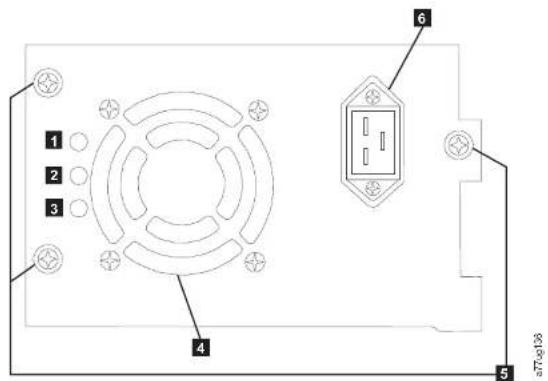
Figure7-1.A250wpowersupplywithLEDs
natural_image
Pure electrical circuit lines without any symbolsIf the Library does not power on:
-
With library power OFF and the power cord unplugged, loosent the three thumbscrews (5), graspt two of the thumbscrews, pull the powersupply out halfway, reseat the powersupply, and tight the three thumbscrews.
-
Ensure the power cord is plugged in at the power supply (6) and at the electrical outlet, then turn library power ON.
a. For powersupplies with LED's, the "Blue" LED will belitif AC power is good.
b. If your powers supply does not have LED's, feel for airflowing out of the cooling fan grill on the car of the library (4). AC is good if air is flowing from the cooling fan grill.
- If power appear to be missing
a.Plugthepowercordintoanotherelectricaloutlet.
b. If power is still missing, plug another device into the outlet to test.
c.IftheoutlettestsOK,tryanotherpowercordwiththelibrary.
-
For powersupplies with LED's, if the "Amber" LED is lit, replace the power supply (referto "Replacing Power Supply" on page 10-10).
-
If your powersupply has not led's, and you have verified that the electrical outlet works properly, but the powersupply is still failing, replace it (referto "Replacing a Power Supply" on page 10-10).
-
If the powersupply seems to be delivered power to the library (Operator Control Panel and front panel LED's maybe functioning); however, air does not flow from the powersupply cooling fan grill on the car of the library, replace the powersupply (referto "Replacing a Power Supply" on page 10-10).
-
If the powersupply seem to be delivered power to the library (Operator Control Panel and front panel LED's may be functioning), and air is flowing from the powersupply cooling fan grill on there are the library, observe the "Green" LED (lowest of the three). If it is, the powersupply is OK.
Note: If your library has -04 level redundant powersupplies (seelabelontop of powersupply), it is normal for the one in "Standby" modetoturnits.
Note: If you are instructed by Dell Technical Support to copy the driven dump to your host computer, use one of the following methods:
- WebUserInterface:Referto"ServiceLibrary:SaveDriveDump" on page5-61.
- ITDT:Referto"UsingtheITDTFirmwareUpdate,DumpRetrieval andDriveTestTool"onpage9-5.
- Ensure that the drive firmware is at the latest level. Todetermine current library and drive firmware version using the OperatorControlPanel:
- Library firmware: Monitor > Library > Identity
- Drive firmware: Monitor > Drives > Identity (select a drive) Drive firmware is identified in the FWRevfield.
- Tryreseatingthedrivesled.
Note: The drivesled is shot-pluggable so it is not necessary to power off the library. See "Removing/Installing/AddingaTapeDriveSled" on page 10-3.
-
Cyclepowertothelibrary.
-
If aird does not flow from the drives led cooling fan grill on there are of the library, replace the drives led CRU. Several library error codes also point to cooling problems. See "Removing/Installing/Adding Tape Drive Sled" on page 10-3.
-
If the drive is experiencing permanent temporary errors or if the amber Clean LED disiton the front panel of the library, select Clean Drive from the Operator Control Panel Service Menu (Service > Service > Clean Drive) and clean the drive. Use only an approved cleaning cartridge (see "Cleaning Cartridge" on page 6-4).
-
Run the Library Verify Diagnostic which includes a drive performance Read/Writetest.Besuretouseaknowngoodscratchorblankdatacartridge. •Ifthedrivetestfails,replacethedrivesledCRU(referto "Removing/Installing/AddingaTapeDriveSled"onpage10-3).
-
If the drive passes all the tests, inspect themediato ensure themedia is compatible with the drive and not causing drive errors. Referto Chapter 6, "Using UltriumMedia," on page 6-1.
- If the card appear stohavenoabnormalities, reseat the card back in the library, tightenthumbscrews, and turn library power ON.
-
If both the Operator Control Panel and Web User interfaces are inoperable or frozen and the latest firmware has been installed, the controller card CRU electronics is themost likely failure. If only the Web User Interface has failed, please see "solating Web User Interface Problems" before replacing any CRUs.
-
If a control card error code has been obtained and reseating, power cycling, and updating the library firmware did not fix the problem, the controller card CRU is chemost likely failing CRU (referto "Replacing a Library Controller Card" on page 10-11).
-
If the error code indicates an accessory type error (slider, elevator, sled, etc.), recascand remove both magazines (see "Control: Magazine" on page 5-17, "ManageLibrary: Release Magazine" on page 5-12, or "Releasing the Magazines Manually" on page 9-1) and observethaccessor path for any obvious obstruction or problems. Resolve any observed problem if possible. Execute a Library System Test. See "Service Library: Perform Diagnostics" on page 5-6 for the web or "Service: Run Tests" on page 5-30 for the OCT if the problem is persistent, contact Dell technical support.
-
If the library is taking an extended amount to time in recovery to complete initialization, perform inventory, or executing a cartridge movement within the library, and, after finding the magazine cell fiducialist possible with no visible damage and correctly installed, suspect the sensor / emitter on the accessor mechanism to be inoperable. Execute a Library System Test. See "Service library: Perform Diagnostics" on page 5-62 for the Webbor "Service Run Tests" on page 5-30 for the OCPI if the problem is persistent, contact Dell technical support.
IsolatingWebUserInterfaceProblems
If the WebUserInterface is not functioning at all or if it is intermittently functioning, review the following steps to ensure that it is properly configured, or, to help determine which CRU or part need to be replaced. The complete Web UserInterface electronics reside on the library controller card CRU.
- Ensure that the ethernet cable is securely plugged in therear of the library at the ethernet port. See 7 on the "RearPanel" on page 1-3.
A F 1.01 4M V: 1 10: 11 1 1: 1
IsolatingAccessorScannerProblems
If the server has reported inventory problems relating to inability to read barcode labels, or, if some oral of the cartridge labels are not being displayed on the Web User Interface, use the following procedure to determine if the scanner (library enclosure CRU) need to be replaced.
- Ensure that as supported barcode label (or labels) are being used.
- With library power OFF, reseathelibrarycontrollercardCRU (referto "ReplacingaLibraryControllerCard" on page 10-11), and henswitchlibrary power ON.
- Performare-inventoryviatheOperatorControlPanel(Control> Re-Inventory) and view the inventory via the Web User Interface (Monitor Library>Inventory) todetermineifthelabelsarenowbeingread.
- If the labels are still not being read properly, please contact Dell technical support.
IsolatingHostAttachmentInterfaceProblems
Aftersuccessfullyexercising"IsolatingDriveSledProblems",andmorespecifically the "Library Verify" diagnostic on the Operator Control Panel (Service > Library Verify)whichincludesadrive(ordrives)read/writediagnostic,thefollowing proceduresaresuggestedtohelpisolatethefailuretoproperlyestablish connectivitytotheHostBusAdapter(HBA).
- Use the utility, ITDT, to evaluate connectivity from the HBA through the cabling to the drive (or drives). ITDT does not require a separated device driver, thus the Operating System has the ability to scan and find all the LTD devices that are attached. If ITDT cannot successfully locate the LTD drive, suspect cabling or IBA problems, and skip step 2. If ITDT successfully located the LTD drive, proceed to step 2. See Using the TDT Firmware Update, Dump Retrieval and Drive Test Tool "on page 9-5 for about brief description of ITDT and instruction on how to download the tool from the web.
- If ITD ^s successfully locates the LTO device(s), verify that the correct application device drivers and backup applications software is properly installed.
-
Ensure that all there required or latest available Operating Systemfiles and/or updates (dll's PTE's etc.) have been installed and applied
-
Remove cartridge. If cartridge was reported as Bad, properly dispose the cartridge.
5.ClosetheI/OStation.IftheamberLEDwaslitbecauseofbadmedia,the AttentionLEDwillturnOFF.IftheamberLEDisstillon,checkthepower supplyorthepowersupplyfans.See"IsolatingaPowerSupplyProblem" on page7-7.
Chapter8.Errorcodes
If an error occurs during operation of the library, the library stops the current operation and displays an error code on the CD screen. Unless otherwise noted in "Errorcodes" on page 8-2, try to resolve the error by cycling power to the library and retrying the last operation. If the error persists, contact technical support.
Exampleerrorcode
EVENT -6
8D 07
Where:
- -6 indicates the position in sequence list, 0 being the most recent.
•8D07indicatestheerror.(code8D=sledblocked,).
Theeventlogwiththelibraryalsoincludesadatestampforeachevent.Press SELECTtodisplaytheassociatedtimestampinthefollowingformat:
yy.mm.dd hh:mm:ss:HH
Where:
•yy istheyear
•mm isthemonth
•dd isthecurrentday
•hh ishours
•mm isminutes
•55 isseconds
•HH is1/100second
Errorcodes
Errorstatarescribedareharderrors. If such an error occurs the library stops allocations and the ErrorLED starts flashing. An appropriate message is posted on the Operator Control Panel and the Web User Interface. These errors are also reported by way of email notification, if enabled. To enable email notifications, refer to "ConfigureLibrary: EventNotification" on page 5-55.
Table8-1.MainErrorCodes
| ErrorCodeDescriptionUserAction | |
| 80Barcodereadererror,cannotinitializeBCR | ErrorCode8101mightbepostedifthelibraryhasaBCR(barcodereader)thatrequiresaminimumlevcloflibraryfirmware.Updatethelibraryfirmwareto9.00orhigher.Iftheproblemstillexists,followtheprocedure.SccfIsolatingLibraryControllerCardvs.AccessorEnclosureProblem"onpage7-10.PossibleReplacementCRUs:Primary:LibraryEnclosureSecondary:LibraryControllerCard |
| 81Harcodereadererror,noresponsefromBCR | |
| 82EEPROMElectricallyErasableProgrammableRead-OnlyMemory)error,noresponsefromEEPROM(locatedonaccessorcontroller) | |
| 83Accessorcontrollergenericproblem | |
| 84Settingofgrippermotorparametersfailed | |
| 85Settingofsidermotorparametersfailed | |
| 86Settingolelevatormotorparametersfailed | |
| 87Settingofrotationmotorparametersfailed | |
| 88Settingofstedmotorparametersfailed | |
| 89Gripperblocked | |
| 8ASliderblocked | 1.IfthisisthefirsttimethatthelibrarywaspoweredONoriftwasmovedtoanewlocation,ensurethattheshippinglockwasremoved.Thelockisonthetopofthelibrary(see"RemovingandStoringtheShippingLock"onpage4-4)2.Referto"IspilatingaLibraryControllerCardvs.AccessorEnclosureProblem"onpage7-10.PossibleReplacementCRUs:Primary:LibraryEnclosure |
| 8BElevatorblocked | |
| 8CRotationblocked | |
| 8DSledblocked | |
| 8FCannotfindgripperblockwithintheexpectedrange | Referto"solatingaLibraryControllerCardvs.AccessorEnclosureProblem"onpage7-10.PossibleReplacementCRUs:Primary:LibraryEnclosureSecondary:LibraryControllerCard |
| 8FCannotfindsliderblockwithintheexpectedrange | |
| 90Cannotfindlevatorblockwithintheexpecteddrange | |
| 91Cannotfindrotationblockwithintheexpecteddrange | |
| 92Cannotfindsledblockwithintheexpecteddrange | |
| 93Gripperoutsiderange,Grippercachedapositionbeyondtheexpecteddrange | |
| 94Slideroutsiderange,Sliderreachedapositionbeyondtheexpecteddrange | |
| 95Elevatoroutsiderange,Elevatorreachedapositionbeyondtheexpecteddrange | |
| 96Rotationoutsiderange,Rotationreachedapositionbeyondtheexpecteddrange | |
| 97Slcdoutsiderange,Slcdrachedapositionbeyondtheexpecteddrange | |
| 98Cartridgepresentsensornotfound | |
| 99Sliderhomesensornotfound | |
| 9ARotationhomesensornotfound | |
| 9IISledpositionsensor(fiducialsensor)notfound | |
| 9CGripperrangesoutofspecification | |
| 9DSlerrangcoutofspecification | |
| 9FElevatorrangeoutofspecification | |
| 9ITrotationrangeoutofspecification | |
| A0Sledrangcoutofspecification | |
| C0NetworkInitializationfailed | 1.Referto"IsplatingWebUserInterfaceProblems"onpage7-11.2.Iftheerrorrecurs,contacttechnicalsupport. |
| C1TelnetInterfaceinitializationfailed | |
| C2Webservinitializationfailed | |
| C6Pingcommandidnotreachtarget | |
| C7CannotUpgradefromUSBNotsupported | |
| C8CannotUpgradefromFTP | 1.RetrytheFirmwareupgrade.2.Iftheerrorrecurs,contacttechnicalsupport. |
| C9CannotUpgradeRoboticfromFlash | |
| D0ROMerror.ROMchecksumincorrectReferto"IsolatingaLibrary | ControllerCardvs.AccessorEnclosureProblem"onpage7-10.PossiblereplacementCRUs:Primary:LibraryControllerCardSecondary:LibraryEnclosure*D7-FatalSystemerrorcanoccurbecaseolanover-temperaturecondition.EnsurethattheenvironmentmectstheEnvironmentalSpecifications(referto"EnvironmentalSpecifications"onpage1-14) |
| D1RAMerror.PoweronSelfTest(POST)failed | |
| D2NVRAM(Non-VolatileRandomAccessMemory)error.Read/WriteoperationtoNVRAMfailed | |
| D3CTC(ChanneltoChannel)Error.TimeunitfailedduringPOST. | |
| D4UART(Universal/AsynchronousReceiverTransmittcr)Error.FrameoverrunorParityErroronserialInterface. | |
| D5DisplayErrorCommunicationtodisplayfailed | |
| D6MemoryError.Stackandheapoverflow. | |
| D7Fatalsystemerror* | **IfyourceivableD&errorwhileyourlibraryconfigurationisrestoredfromtheOCPorWebUI,verifythatyourfileextensionis.dbb.Iftheextensioniscorrect,yourfilewascorruptedduringthesave.Reconfigure,thensaveyourlibraryconfiguration.Note:Configurationfilesthataresavedwithoneversionoflibraryfirmwaremightnotbecompatiblewithotherversionoffirmwaren Libya |
| D8Databaseerror** | |
| D9NoSCSITCdetected | |
| DEWarningEvent!SeeTable8-3ompage8-11 | |
| DFWarningEvent!SeeTable8-3ompage8-11 | |
| E0Incompatiblemagazinethatisdetected | 1.Removemagazinefromlibrary.2.Insertmagazineinlibrary.Iferrorrecurs,contacttechnicsupport. |
| E2Newhardwarefound.Libraryfirmwarecupgradesrequired.Upgradelibraryfirmwarectothelatestversion. | |
| EBPowersupplyhealthcheckfailedbecauseofapowersupplyfailure. | Referto"IsolatingaPowerSupplyProblem"onpage7-7 |
| F0DriveOvertemperatureConditionThesubcodeindicateswhichdriveisaffected.Example:Subcode02:drive#2 | 1.Checktheambienttemperatureconditions,andcheckallfans.2.Referto"IsolatingDriveSledProblems"onpage7-9. |
| F1DriveCommunicationErrorLibrarycontrollerlostcommunicationtodriveThesubcodeindicateswhichdriveisaffected.Example:Subcode02:drive#2 | Referto"IsolatingDriveSledProblems"oupage7-9. |
| F2DriveSlednotpresentThesubcodeindicateswhichdrivesledisaffected.Example:Subcode02:drivesled#2 | |
| F3DriveHardwareErrorThesubcodeindicateswhichdriveisaffected.Example:F5xyWherexreferstothehardwarerivererrorcode(singlecharacterdisplay)andYreferstothedrivepositioninthelibrary.xvalues:4:firmwarcorhardwareerror5:hardwareerror6:hardwarecormediacerrorA:recoverablehardwareerror | |
| F4DriveLoadTimeoutDriveruninatimeoutwhiletapeisloading.Thesubcodeindicateswhichdriveisaffected. | |
| F6Nodriveinstalled.Adrivewasneverinstalled | Referto IsolatingDriveSledProblems*onpage7-9. |
| F7Supportticketdownloadfromdrivenotpossible | |
| F8Invaliddrivecommand | |
| F9Invaliddriveparameter | |
| FA5DCImicrocodeerror | |
| FBDriveloggedout | |
| FCInternalSCSlcommandfailedwithcheckcondition | |
| FDInternalSCSlcommandtimeout | |
SubErrorCodes
Table8-2.Suberrorcodes
| ErrorCodeDescription | |
| ROBOTICS | |
| 00Nosuberrorcode | |
| 01Mochanicalinitializationfailure | |
| 02Connectiontoslaveroboticfailed | |
| 03Errormotorinitialization | |
| 04Errorduringgripperclose | |
| 05Errorsliderhomepositioning | |
| 06Errorlevatorhomemovement | |
| 07Errorduringsledmovementtorotationposition | |
| 11Errorduringsliderhomemovement | |
| 12ErrorduringrotationtoFARposition | |
| 13Errorsledinit,movctosensorfailed | |
| 14Errorduringsledmovement;checkshippinglock | |
| 15Errormovetoacertainpositionfailed | |
| 16Errorpositioningoftherotationmotorfailed | |
| 20ErrorInventoryscan | |
| 21Errorduringgripperclose | |
| 22Errorsliderhomemovement | |
| 23Errorduringmovegrippertoscanpos | |
| 24Errorreadingbarcodelabel | |
| 25Errorduringmovesledtoscanposition | |
| 26Errorduringmoveelevatortoscanposition | |
| 27Errorduringsledprepositionmovement | |
| 28ErrorExtrainInventoryscan | |
| 29Errorduringclosinggripper | |
| 2AErrorsliderprepositionmovement | |
| 2BErrorduringopeninggripper | |
| 2CErrorduringsledmovementuptosensor | |
| 38ErrorduringsledpositioningtomailslotinFLMoveSledfunction | |
| 39Errorduringsledpositioningwithoutsensor | |
| 3AErrorduringelevatoromovementwithoutsensor | |
| 3BErrorslotpositionsensornotfound | |
| 40Movementto/fromslotfailed | |
| 41Errorduringfirstslidermovement | |
| 42Errorduringfirstgrippermovement | |
| 43Errorduringsecondslidermovement | |
| 44Errorduringsecondgrippermovement,getrangefailed | |
| 45Errorduringthirdslidermovement,movchomefailed | |
| 46Errorduringsetholdcurrenttoavoidtorsion | |
| 47Negativedirectionblocked | |
| 48Positivedirectionblocked | |
| 49Possiblemotordefect,becausebothdirectionsblocked | |
| 4ACartridgepresentsensordefect | |
| 4BINventorylost,becausedestinationpossiblyfull | |
| 4CInventorylost,becausesourcemightbecempty | |
| 4DCouldnotpulltapeoutofslotfrommagazine | |
| 4EUnexpectedtapeonelevator,possibleinventorylost | |
| 50Prepositiontodrivefailed | |
| 51Elevatoromovementtohomesensorfailed. | |
| 52Sledmovementtohomesensorfailed. | |
| 73Errorduringmovelesledtoblock. | |
| 80Opening1/Osletfailed. | |
| 81Errorduringmovementtol/Oslotopenposition. | |
| 82Errorduringmovingback-sensorwasfound. | |
| 90Movementtohomepositionfailed. | |
| 91Elevatormovementtohomepositionfailed. | |
| 92Errorduringsledmovementtorotationposition. | |
| 93Errorduringrotationtohomeorfarposition. | |
| 94Sledmovementohomesensorpositionfailed. | |
| 95Sledmovementotransportpositionfailed. | |
| 99Errorduringrotationmovementtorotationminposition. | |
| A0Movementtol/Oslotfailed. | |
| A1Sledmovementosensorfailed. | |
| A2Sledmovementorotationpositionfailed. | |
| A3Elevatormovementtohomepositionfailed. | |
| A4Errorduringrotationtofarposition. | |
| A5Sledmovementtol/Oslotpositionfailed. | |
| A6Errorduringelevatormovementtoposition | |
| A7Errorduringmailslotdetection | |
| B0EEPROMonroboticscontrolcrnotaccessiblecorerrorduringRead/Writeoperation | |
| B1 | Save/restoreconfigurationsettings:notenoughinternalmemoryavailableforcreatingthefileand restoringthefilerespectively |
| B2 | Save/restore configuration settings: restore buffer corrupted, checksum calculation failed |
| B3Save/restoreconfigurationsettings:databasefieldcorrupted | |
| B4Save/restoreconfigurationsettings:invalidpersonality | |
| B5Save/restoreconfigurationsettings:invalidfile | |
| 97Slotnotfreeatrobotunload | |
| 98Cartridgesotscatedinloadphase | |
Warningevents
Warningeventsthataredescribedarereportedbywayofemailnotification.The AttentionLEDflasheswhenwarningeventsforthefollowingoccur:
•Media
•Fan
•Redundantpowersupply
AnappropriatemessageispostedontheOperatorControlPanelandtheWebUserInterface.
Table8-3. Warningevents
| 30SCSI:transportelementfull | Refertoyourhostapplicationdocumentationforproblem determinationinformation. |
| 31SCSI:allslosemempty | |
| 32SCSI:invalidopcode | |
| 33SCSI:invalidelementaddress | |
| 34SCSI:invalidfieldinCDB | |
| 35SCSI:invaliddrivespecified | |
| 36SCSI:SENDI/DIAGNOSTICcommand:invalidtestnumber | |
| 37SCSI:invaliddLUN | |
| 38SCSI:parameterlistlengthterror | |
| 39SCSI:parameterlisterror:invalidfield | |
| 3A5CSI:parameterlisterror:parameternot supported | |
| 3B5CSI:parametervalueucinvalid | |
| 48SCSI:driveHypernotsupportedinthis library | Checkwhetheraversionoffirmwareisavailablethatsupportsthisdrivetype.Foralistofsupporteddrives,refer to"Ultrium TapeDrives"onpage1-9. |
| 49SCSI:incompatiblemagazine,magazine notaccessible | Checkyourconfigurationsettings. |
| 4ASCSI:sourenotready | Complectemoveprocessandretryoperation. |
| 4BSCSI:destinationsourcenotready | |
| 4CSCSI:librarycontrollerbusyCompleteprocessandretryoperation. | |
| 4DSCSI:Cannotmakerreservation | Refertoyourhostapplicationdocumentationforproblem determinationinformation. |
| 4ESCSI:invalidslaveroboticontroller rquest | |
| 4FSCSI:roboticaxes/motorsaren't initialized | Checkroboticsstatus.Referto"Islatingal library ControllerCardvs.AccessorEnclosureProblem"onpage 7-10. |
| 50SCSI:cartridgebelongstoanother partition | Checkapplicationsoftware. |
| 51IncompatiblemcellumCheckthecompatibilityofmediaanddrivegeneration. | |
| 52Allslotsfull,nomovementpossibleRemoveacartridgetomakeamovepossible. | |
| 53AllslotemptyrequiredforwellnesstestFilluprequiredslotsbeforethewellnesstestissarted. | |
| 54SCSI:failuncinLMEinterface | 1.CheckyourEncryptionconfiguration.2.RunKeyPathDiagnostics.3.RefertotheIBMSKLMKnowledgeCenteronlinefor information. |
| 55SCSI:invalidlicensekeyenteredRecenterlicensekey.Ifproblempersists,refertotechnical support. | |
| 58RecoveredError:SCSlparityerror | Nouscractionisrequired. |
| 59RecoveredError:Errorlogoverflow | |
| 5Allegalrequest,downgradeprohibited Disableencryptionforfirmwaredowngrade. | |
| 5BIncompatiblemediumgeneration Replaceincorrectcartridges. | |
| 65Invalidupgradecartridge.Driverrejectedthcupgradecartridgecasinvalid | Notsupported |
| 66Mediumerror:diagnostictapewriteprotected | Ensurethatdiagnostictapeisnotwriteprotected. |
| 67Mediumerror,incompatiblemediumforwriteoperation | Replaceincorrectcartridges. |
| 6AMediumerror.noOBDRtapeInsertOBDRtape. | |
| 70Currentlynotused | |
| 71Currentlynotused | |
| 72Currentlynotused | |
| 73SCSI:overclappedcommandattempt | Refertoyourhostapplicationdocumentationlorproblemdeterminationinformation. |
| 74SCSI:echobufferoverwritten | |
| 75Downloadpreventedduetoincompatiblcbarcodrcaderhardware | Olderfirmwareimagedoesn'tsupportcurrentbarcodcraderhardware.Nodowngradepossible. |
| 77DownloadpreventedduetoincompatibieLCM | Olderfirmwareimagedoesn'tsupportcurrentlibrarycontrollerhardware.Nodowngradepossible. |
| 78DownloadpreventedduetoincompatibieRobCode | Olderfirmwareimagedoesn'tsupportcurrentroboticscontrollerhardware.Nodowngradepossible. |
| 79Downloadpreventedduetoincompatibledriveversion | Usecorrectdrivefirmwareimage. |
| 80MovementRetry. | |
| 81FanAlert. | |
| 82Cleanrequestfromdrive. | |
| 83MediaAttention. | |
| 84Drivereportedwarningorcriticaltapealertflag. | |
| 85Networkproblem.Checknetworkconnections,configuration,andsettings. | |
| 86Notenoughcleaningcartridgespresenttoautoclean. | Insertmorecleaningcartridgestotheemptyreservedslots. |
| DBExternalcoolingfanerror(fanmotion stopped). | Referto*IsolatingDriveSledProblems"onpage7-9. |
| Thesubcodeindicateswhichdrivesled fanisaffected | |
| Subcode01:drivesled#1(bottom) | |
| Subcode02:drivesled#2 | |
| DC | FCIbusFailure |
| DDPowerSupplyxfanfailed, | Referto*IsolatingaPowerSupplyProblem"onpage7-7. |
| Redundancymightbeatrisk | |
| Thsubcodindicateswhichpower supplyfanisaffected | |
| Subcode01:1stPSlanfrombottom | |
| Subcode02:2ndPSlanfrombottom | |
| DFPowerGoodsignalthatischangedfrom 2to1PowerSupplies | |
| F6Nodriveinstalled.Adrivewasnever installed. | Installatleastonedrive. |
Chapter9.ServiceProcedures
Removing Cartridges from Magazine Slots
Intheeventofaseveremechanicalproblemwiththelibraryorifcircumstances
requireyoutoremovetapecartridges,dothefollowing.IftheOperatorControl
PanelortheWebUserInterfaceisstilloperational:
- Move the tapes from the drive(s) to the magazines using the Manage Library >Move Media command (Web User Interface) or Control >Move Cartridges command(OperatorControlPanel).See "ManageLibrary:MoveMedia" on page5-41dr "Control:MoveCartridges" on page5-17.
Note: Contact technical support if a car tridgewill note eject from the drive.
- Use themagazineremoval processtoreleasethemagazineandremoveitfrom thelibrary.TousetheOperatorControlPanel,see"Control:Magazine"onpage 5-17.TousetheWebUserInterface,see"MarageLibrary:ReleaseMagazine" onpage5-42.Ifneitheroneoftheseprocessesworks,see"Releasingthe MagazinesManually."
ReleasingtheMagazinesManually
If the directions in Steps1 and 2 aboved on to allow y out or mov et tapes, do
thefollowing:
1. Unplugthepowercordfromthelibrary.
2. Find the accessholes for theright and left magazines.
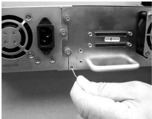
natural_image
Close-up of a hand inserting a cable into a computer drive module (no visible text or symbols)a77ug025
Figure9-1.Accessholesfortheleftmagazine
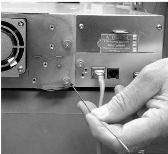
877ug024
Figure9-2.Accessholesfortherightmagazine
3.Tomanuallyreleasethemagazines,pushtheendofastraightenedpaperclip intotheaccessholeforeachmagazineatthebackofthelibrary.Whileholding thepaperclip,haveasecondpersonpullthemagazineoutofthefrontofthe unit.DONOTpushthepaperclipinmorethan1/2inch.
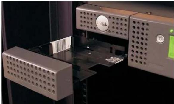
natural_image
Close-up of a 3D printing machine with perforated metal components and control panel (no visible text or symbols)Figure9-3.Leftmagazinepulledoutofthe2Ulibrary
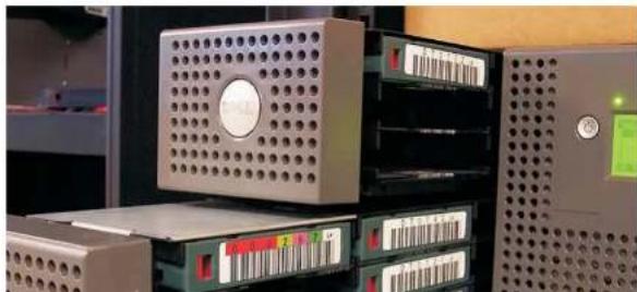
natural_image
Industrial hardware unit with perforated metal enclosure and multiple drive bays (no visible text or symbols)UsingtheITDTFirmwareUpdate,DumpRetrievalandDriveTestTool
ITDThasmultiplefunctionalcapabilityandisaveryquick,convenientand efficientmethodfordrivefirmwareupdates.Asanote,drivedumpretrievalscan beperformedbythetoolaswell.
TheITDTTool:
- Runsquickorextendeddiagnosticsontapedrives. If the library is on lineto the server / host where the tool resides, ITDT will communicate with the drive through the library to load and unload at test cartridge thereby exercising some library functions.
•Retrievesfirmwaredumpsfromtapedrivesandlibraries. - Perform sa firmware update on taped drives or libraries. Seen note below regarding library firmware update.
- Teststheperformanceoftheenvironmentbycompletelywritingacartridgeand measuringperformance.
•Retrievesanddisplayscartridgeinformation. - Verifiestheencryptionenvironment.
- Does not require special device drivers.
•Isavailableformostmajorplatforms.
Note: ITDT Version7 or higher is required for Ultrium5 and Ultrium6 tape drives. Before using ITDT, verify that your library host operating system is athelatest released level. This will ensure optimum read/write operations for diagnostics.
Note: If the library has a BCR (Barcode Reader) that requires 9.00 or greater firmware, the Update function will terminate with an error code of "UnexpectedData" if you attempt to down level the library firmware.
TodownloadtheITDTtoolandinstructionsforusingthetool,visit http://support.dell.com.
Chapter10.Check,Adjust,Remove,andReplace
ToolsRequired
Toservicealibraryyoumayneedoneormoreofthefollowingtools:
•#2Phillipsscrewdriver
•Groundstrap(recommended,ifavailable)
ElectrostaticDischarge
Important: Adischargeofstaticelectricitycandamagestatic-sensitivedevicesor microcircuitry. Properpackagingandgroundingtechniquesare necessaryprecautionstopreventdamage.

Figure10-1.ESDlabel
Topreventelectrostaticdamage,observethefollowingprecautions:
- Transportproductsinstatic-safecontainerssuchasconductivetubes,bags,or boxes.
- Keepelectrostatic-sensitivepartsintheircontainersuntiltheyarriveatstatic-free stations.
• Cover the unit with approved static-dissipating material. If available, provide a ground strap connected to the works surface and properly grounded tools and equipment. If a ground strap is not available, touch metals surface to discharge an static electricity in your body. - Keep the work area a free of no conducting materials, such as ordinary plastic assembly aids and foam packing
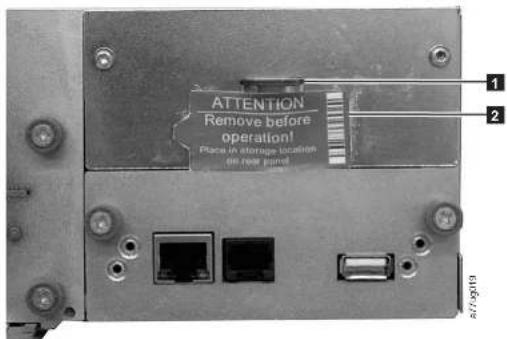
Figure10-2. ShippingLockandLabelStorageLocation
- Insert the shipping lock (1) into the slot located on the center of the top of the library and secure with the shipping label (2).
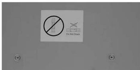
Removing/Installing/AddingaTapeDriveSled
There are two types of drives led by a TL2000 library (2 Library) and a TL4000 library (4 Library). The content of the ship groups are specific to the type of drives led.
- DrivesledwithoutElectroStaticDischarge(ESD)springs(seeFigure10-4)ship group:
-DrivesledwithoutESDsprings
-PacketofconductivetapetobeappliedtothedrivesledforESDprotection
- DrivesledwithESDsprings(seeFigure10-5onpage10-4)shipgroup:
-DrivesledwithESDsprings
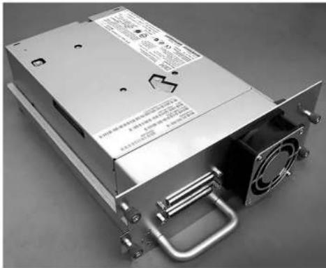
a77ug008
Figure10-4. LibrarydrivesledwithoutElectroStaticDischarge(ESD)springs(SCSIsledshown)
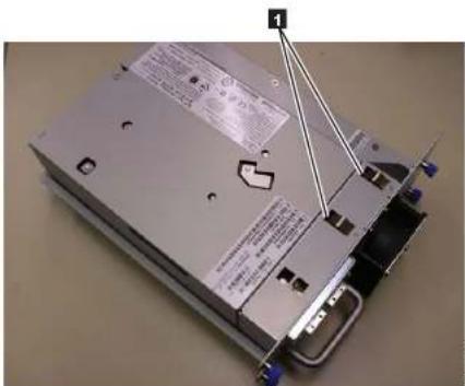
Figure 10-5. Library drives led with ESD springs1
RemovingaTapeDriveSled
- ITISIMPORTANTTOPRESERVEADRIVEDUMPFORANALYSISIFALLOF THE FOLLOWING CONDITIONSEXIST:
•LibraryErrorLEDisON.
•OperatorControlPanelisdisplayadriveerrormessage.
- WebUserInterfaceSystemStatusscreenisindicatingthatadrivehasfailed.
IFNONE OF THE CONDITIONS LISTED ABOVE EXIST, PROCEED TO THE NEXT STEP.
- PowerOFFthelibrarybeforeremovingand/orinstallingaSCSIdrivesled.
FibreChannelandSASdrivesledsarehotpluggableandmayberemovedand installedwhilethelibraryispowercdON.

Figure 10-6. Drive sled components (full height fibre drive in top position, half height SCSI drive in middle position, half height SASdriveinbottomposition) on backpanelofa4Ulibrary
| 1 | SCSlscable |
| 2 | SAScable |
| 3 | SCSItcrminator |
| 4 | FibreChannelcable |
| 5 | Ethernetcable |
| 6 | Powercords |
| 7 | Drivesledbluecaptivethumbscrews |
| 8 | Blackpullouttab |
| 9 | Drivesled |
| 10 | Drivesledhandle |
F17 1 1 1 1 1 1 1 1 1 1
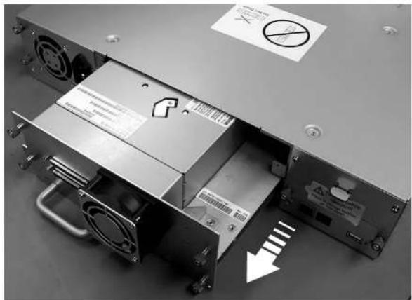
natural_image
Interior view of a computer drive bay with cooling fans and a power supply unit, showing no visible text or symbols.Figure 10-7. Pulling the drives led out of the library (drives led without ESD spring shown)
InstallingaTapeDriveSled
Note: PowerOFFthelibrarybeforeinstallingaSCSldrivesled.FibreChanneland SASdrivesledsarehotpluggableandmayberemovedandinstalledwhile thelibraryispoweredON.
Important: Ina4Ulibraryafullheightdrivesledmaybeinstalledindriveslot1 (drivewilloccupyslot1andslot2)ordriveslot3 (drivewilloccupy slot3andslot4). Afullheightdrivesledshouldneverbeinstalledin driveslot2 (drivewilloccupyslot2andslot3).
1 Before installing the new driversled inspect all connectors on the driversled
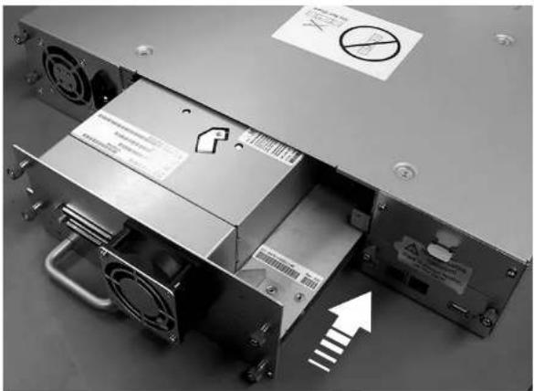
natural_image
Interior view of a computer drive chassis with cooling fans and a power strip, showing no visible text or symbols.Figure10-8. Pushing the drives led into the library (drives led without ESD spring shown)
- Tighten the captive thumbscrews (7) in Figure 10-6 on page 10-5 until the drivesledissecure.
- If you are installing a drivesled without ESD springs (see Figure 10-4 on page 10-3), apply conductive etapeto the sales shown in Figure 10-9 on page 10-8.
2U Library
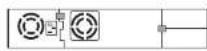
4U Library
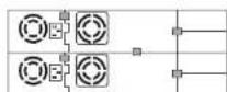
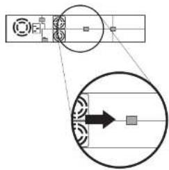
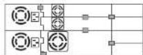
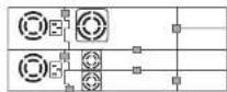
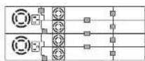
a77ug203
Figure 10-9. Diagrams for applying conductivetapefor ESD protection to the back of a drives installed in 2 U or 4 U library
Note: Thesmallgraymarkersshowwhereconductivetapeshouldbeplaced toprovideESDprotection.
-
Push the black tab (8 in Figure 10-6 on page 10-5) back underneath the library. When inserted properly, only the handle of the tab will be visible.
-
Upgradlibraryfirmwareanddrivefirmwarectothelatestversion. Referto"ConfigureLibrary:Drives"onpage5-48toconfigurethedriveiftisaSCSlorFCdrive.ConnectthedrivehostinterfacecabletothehostorFC switch.
Important: If the failed drivewas configured forencryption, to ensure the replacement driver receive the proper encryption parameters, resubmit the encryption choices listed on ConfigureLibrary> Encryption for that particular drive or logical library even if the encryption settings did not change.
AddingaTapeDriveSled
Usetheseinstructionstoaddanewtapedrivetoyour2Uor4UTapel.library. RefertoAppendixA, "SCSIElementTypes, SCSIAddresses,andPhysical Configurations,"onpageA-1for-moreinformation.
Note: PowerOFF the library before installing a SCSI drives led. Fibre Channel and SAS drives leds a rehot pluggable and maybe removed and installed while the library is powered ON.
Important: Ina4 Library a full height drivesled maybe installed in driveslot1 (drivewilloccupyslot1 and slot2) or driveslot3 (drivewilloccupyslot3 and slot4). A full height drivesled should never be installed in driveslot2 (drivewilloccupyslot2 and slot3).
Completethefollowingproceduretoaddanewtapedrivetoyourlibrary.
-
Before installing thenewdrivesled, inspect all connectors on the drivesled. Ensure that the connectors are intact, free of any foreign objects, and have no cracks, deformed, or bent contacts.
-
Slowly insert then new drives led into the drives slot while supporting the bottom of the drives led (see Figure 10-8 on page 10-7). In necessary, ensure that the black tab remains extended (in Figure 10-6 on page 10-5). Pushion the drives led handle (in Figure 10-6 on page 10-5) while supporting the bottom of the drives led until it is properly scaled.
Important: Damagetothec connectorpins may occur if this procedure is not followed.
-
Tighten the captive thumbscrews (7) in Figure 10-6 on page 10-5 until the drivesledissecure.
-
If you are installing a drives led without ESD springs (see Figure 10-4 on page
ConfiguringtheTapeDrive
1.LogontotheWebUserInterface.
2. Verify that you are running the latest version of Library and Drive firmware. Upgrade the firmware at Service Library > Upgrade Firmware.
3. Use the Web UI to update the Logical Library (Configure Library > Logical Libraries) and Drive (Configure Library > Drives) configurations. Refer to Chapter 5, "Operations," on page 5-1. Select Submit on the Configure Library >LogicalLibrarieswebpageocveniftherearencorequiredchanges.Thisaction willrefreshtheDataTransferElement(DTE)forthedrives.Referto AppendixA,"SCSIElementType,SCSIAddresses,andPhysical Configurations,"onpageA-IfInformationregardingDTEaddressing.If Configure Library > Logical Libraries does not correctly refresh/update the DTEaddresses,executestep3andstep4. Otherwise,proceedtoStep5.
4. ReconfigureyourlibraryusingtheOCPtoconfigureyournetworksettings, thenusingtheWebUltocompleteyourlibraryconfiguration.
5.SaveyourlibraryconfigurationtoyourhostcomputerortoaUSBdevice.
6. Update your Library Configuration Form with thenew drive and configuration information.
7. Resumenormallibraryoperations.
ReplacingaPowerSupply
- PowerOFFthelibrarybypassingandholdingdownthepowerbuttonfor4 seconds.
- Disconnect the power cord from the electrical source, then from the library.
- Loosenthethreebluecaptivethumbscrewsonthepowersupplylocatedon thebackpanelofthelibrary.
- Pullontwoofthethumbscrewstopulltheunitawayfromtherearpanelof thelibrary, thengraspthetopandbottomedgeofthepowersupplyandpull itoutofthelibrary.
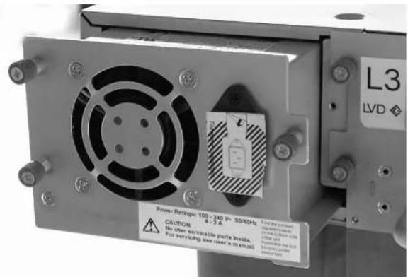
Figure10-10. Apowersupplybeingremovedfroma2Ulibrary
- Removethepackaging from thereplacement powersupply.
- Graspthetopandbottomedge of the powersupply and push it into the library.
- Tightenthethreebluecaptivethumbscrewsonthepowersupplylocatedon thebackpanelofthelibrary.
- Connect the power cord to the library, thentoth electrical source.
9.PowerONthelibraryusingthepowerbuttononthefrontpanel. - RuntheLibraryVerifytest(referto"Service:LibraryVerify"onpage5-29).
11 Packagethefailedpowersupplyinthesamepackaginginwhichthenew powersupplywasshippedtoyouandreturntoDell.
Ifthemessage"VPDSelection"isdisplayedattheOperatorControlPanel, carefullyhighlightthe"VPDfromEnclosure"optiontocopythatversionoftheVPDtothenewLibraryControllerCard.Thencontinuewiththeprocedure.
RemovalandReplacement
-
PowerOFFthelibrarybypassingandholdingthepowerbuttonatthefront ofthelibraryfor4seconds.
-
Disconnect the power cord from the electrical source, then from the power supply or supplies at the back of the library.
-
LoosenthetwobluccaptivethumbscrewsontheLibraryControllerCard.
-
GraspthetwothumbscrewsandpullthedefectiveLibraryControllerCard outofthelibrary.
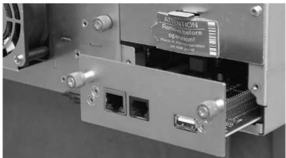
Figure10-11.ALibraryControllerCardbeingremovedfromthelibrary
-
RemovethepackagingfromthereplacementLibraryControllerCard.
-
GraspthetwothumbscrewsandpushthereplacementLibraryController
ReplacingCartridgeMagazines
Toreplaceacartridgemagazine, refertoone of the following procedures:
- Using the WebUser Interface, refer to "ManageLibrary:ReleaseMagazine" on page5-42.
•UsingtheOperatorControlPanel,referto"Control:Magazine"onpage5-17.
- If your library cannot be powered ON, refer to "Releasing the Magazines Manually" on page 9-1.
ReplacingtheLibraryEnclosure
This procedure is necessary when the library enclosure, accessor, or display fails. These components are contained within there replacement library enclosure.
Important: RefertotheInstallationInstructionsthatareincludedwiththenew replacementlibraryenclosure. Follow the procedures included in this document for replacing the Library Enclosure, only if Installation Instructions are not included with thenew replacement library enclosure.
Thereplacementlibraryenclosureincludescartridgemagazines,apowersupply,a LibraryControllerCard,andapacketoflibraryfootpads. Theseitemsare includedwiththereplacementlibraryenclosuredureutosafetyagencyrequirements. Theseunusedpartswillberemovedfromthereplacementlibraryenclosureand returnedtoDellinthedefectivelibrary.Theoldpartscurrentlyinyourdefective librarywillberemoved,andinstalledintotheresplacementlibraryenclosure.
Note: Toreducetheriskofpersonalinjuryordamagetoequipment:
•observelocalhealthandsafetyrequirementsandguidelinesformanual materialhandling
• obtain adequate assistancetolift and stabilizethelibrary during installation or removal
MinimumInstallationTime: 1 h r.
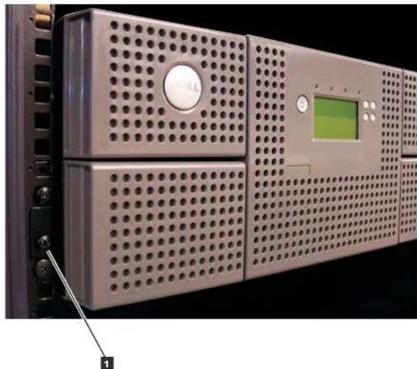
natural_image
Close-up of a server rack with perforated panels, a green screen, and a button (no visible text or symbols)Figure 10-12. Removing the two mounting brackets, screws anchoring the library to the rack (onescrew one each side of the library)
-
Placethedefectivelibraryonacleanandsturdyworksurface.
-
Proceed to "Unpacking and Preparing the Replacement Library Enclosure."
UnpackingandPreparingtheReplacementLibraryEnclosure
Beforeinstallingthereplacementlibraryenclosure,itisimportanttoverifythatthe
b. Foradesktoplibrary:
1) Carefully, laythelibraryonitsside.
2) Peeltheadhesive from the back of each of these six foot pads.
3) Install the footpad son the bottom of the library enclosure bypassing
eachfootintooneofthesixareas(1)asshowninFigure10-13.
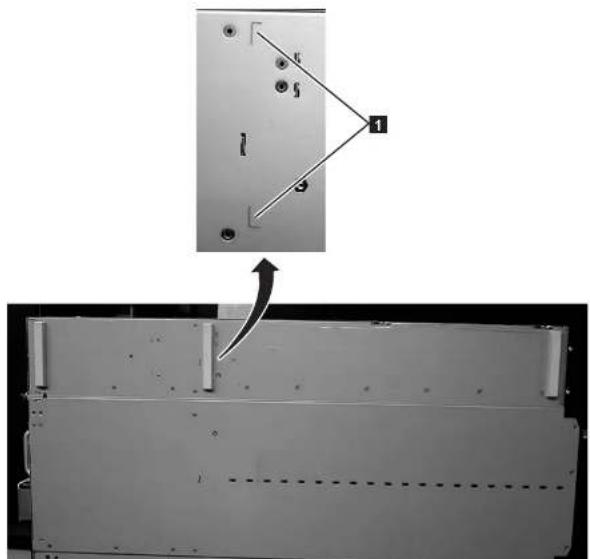
natural_image
Diagram showing a mechanical assembly with a bracket and a dashed-line panel, no visible text or symbols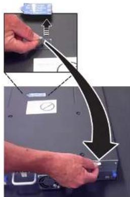
5779195
Figure10-14.Removingtheshippinglabelandlockfromthetopofthelibraryandstoringontherearpanel
- Storethelockandlabelonthecbackpanelofthereplacementlibraryenclosure (see Figure 10-15).
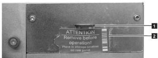
- Remove all drives from the defective library (see Figure 10-16) and install them in the same positions in the replacement library enclosure.
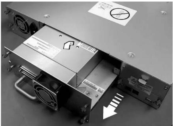
natural_image
Interior view of an electronic device showing a power supply unit with cooling fans and a warning sign (no readable text or symbols)Figure 10-16. Removing a drives led from the library (drives led without ESD spring shown)
a. Ensure that the power cord is unplugged from the powers or source for each powers supply in the defective library enclosure.
b. Ontherearofthedefectivelibrary, loosenthebluecaptivethumbscrewson thedrivesled.
c. If necessary, removethe conductivetape from the drivesled.
d.Pullbackonthetapedrivehandletoremoveitfromthelibrary.
e.Ontherearofthereplacementlibraryenclosure,extendtheblackpull-out
2U Library
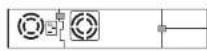
4U Library

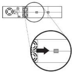
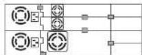
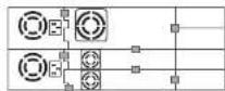
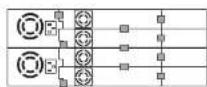
a77ug203
Figure10-17. Drivesledtapingdiagrams
Note: The gray markers show where conductivetapeisplaced.
-
Push the black tabback underneath the drives led. When inserted properly, only the handle of the tabis visible.
-
PowerONthereplacementlibraryenclosure.
a. IfpowerONissuccessful,
1) Afterpowerup, theReady/ActivityLED(1) inFigure 10-20onpage
10-22 turnsON.
a) If this message is displayed after the library powers ON, follow the instructions.
- SwapthePowerSupplyinthedefectivelibrarywiththePowerSupplyinthe replacementlibraryenclosure.
a. Removethepowersupply from the defectively library and from the replacement library enclosure. Toremoveapowersupply from alibrary: 1) Loosenthethreebluccaptivethumbscrewsonthepowersupply. 2) Pullontwoofthethumbscrews, onoppositesidesofthepowersupply, and pulltheunitaway from therearpanelofthelibrary. 3) Grasphetopandbottomedesofthepowersupply and removeit from the library.
b.Installthepowersupplyremovedfromthereplacementlibraryenclosurein thedefectivelibrarytoretumtoDell.Toinstallapowersupply: 1)Whilcsupportingthepowersupply,alignthepowersupplywiththe grooveintheenclosuresrails. 2)Pushthepowersupplyforwarduntilitisproperlyseated. 3)Tightenthethumbscrews.
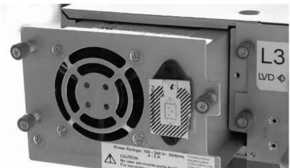
SwappingLibraryControllerCards
IMPORTANT-READMEBEFORECONTINUING
TheLibraryEnclosurecontainsacopyofthevitalproductdata(VPD)foryourlibrary.TheVPDcontainsyour currentlibraryconfiguration.AprimarycopyofthisVPDiscontainedwithinthelibraryControllerCard.Abackup copyofthisVPDismaintainedtheaccessorinthenclosure(orchassis).WhenthelibraryEnclosures replaced,thenewenclosureeelectronicsshouldcontainzeros(f's)inkeyVPDlocations.Upondetectionofthese zeros,thelibrarywillautomaticallywriteVPTdatatotherplacementlibraryenclosurefromtheprimarycopyof theVPDcontainedinthelibraryControllerCard.Inraroccurrences,thereplacementlibraryenclosuremay containvalid(non-zero)VPDdataleftoverfromhavingbeecinstalledpreviouslyinanotherlibrary.Ifthisoccurs, thelibraryfirmware,whisicexpectingtoseezerosintheVPDarea,willinsteaddetectvalidVPDdata,andwill notknowwhichcopyoftheVPTdisthecorrectone.ItwilldetectthisVPDnismatchanddisplayamessage entitled "VPDSlection"onthcOperatorControlPanel.Thelibrarywillncdyourinputtodeterminewhichcopy ofVPDtowritetothereplacementlibraryenclosure.Ifyouarereplacingboththe libraryenclosureandthe LibraryControllerCard,transferVPDafterinstallingonepartbeforeinstallingtheother.
Ifthemessage"VPDSelection"isdisplayedattheOperatorControlPanel, carefullyhighlightthe"VPDfromController"optionbeforeselectingOK.ThiswillcopyVPDfromthecontrollertothereplacementlibraryenclosure.
- SwaptheLibraryControllerCardinthedefectivelibrarywiththeLibraryControllerCardinthereplacementlibraryenclosure.
a. RemovetheLibraryControllerCard(seeFigure10-19onpage10-21)inthe defective library and in there replacement library enclosure. Toremovea LibraryControllerCard:
1) LoosenthetwobluecaptivethumbscrewsontheLibraryController Card.
2) Graspthethumbscrewsandpullthecardoutofthelibrary.
b.InstalltheLibraryControllerCardfromthedefectivelibraryinthe replacementlibraryenclosure.InstalltheLibraryControllerCardfromthe replacementlibraryenclosureinthedefectivelibrarytoreturntoDell.To installaLibraryControllerCard:
1) GrasptheLibraryControllerCardfaceplateandaligntheLibraryControllerCardwiththegrooveintheenclosurerails.
2) Push the Library Controller Card forward untilitis properly seated.
Note: You will hear as nap when the Library Controller Card is fully
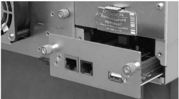
46011998
Figure10-19.RemovingaLibraryControllerCardfromthelibrary
Note: If you power on the replacement library without first swapping the Library Controller Card from the original (defective) library enclosure, the following message will appear on the Operator Control Panel shortly after applying power: "New library detected. Please removal library power and insert Library Controller Card from old Library". The library requires the library serial number and other library attributes from the original all library which is located in the VPD on the original all library Controller Card in order to continue library initialization. See Important-Read Me Before Continuing message listed above.
Asafurther Note, if thereplacementlibrarydoes not complete libraryinitializations successfully alterswapping in the original LibraryControllerCard, besuretoretain the original library ControllerCard so it can be swapped into the "new" replacement library enclosure which will have to be ordered.
1) The Error LED (4 in Figure 10-20) will turn ON. This indicates that the LibraryControllerCardfromthedefectivelibraryisnotfunctioning properly.
2) PowerOffthereplacementlibraryenclosure.
3) Referto Dell technical support for further instructions.
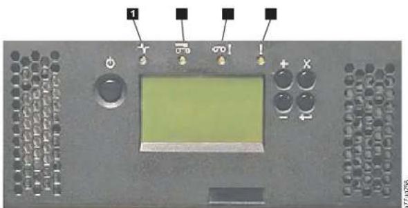
Figure10-20.LibraryfrontpanelLEDs
| 1 | Ready/ActivityLED(green) | 3 | AttentionLED(amber) | |
| 2 | CleanDriveLED(amber) | 4 | ErrorLED(amber) |
SwappingCartridgeMagazines
- Manually release and remove all magazines from the defective library and from
thereplacementlibraryenclosure. Toreleaseandremoveacartridgemagazine:
a. Find the access holes for the right handle left magazines (see Figure 10-21 on page 10-23 and Figure 10-22 on page 10-24).
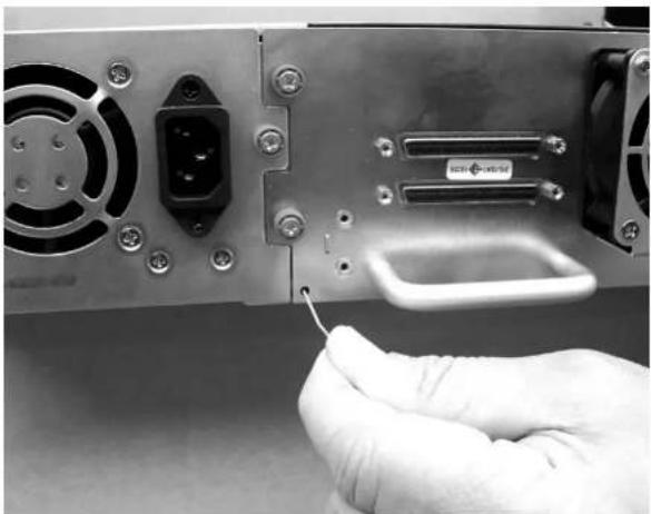
natural_image
Close-up of a hand inserting a cable into a computer drive module (no visible text or symbols)Figure10-21. Accessholefortheleftmagazine(facingrearoflibrary)
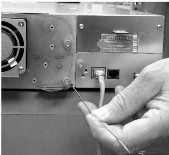
Figure 10-22. Accessholefortherightmagazine(facingrearoflibrary)
b. Pushtheendofastraightenedpaperclipintotheaccessholeforeach magazineatthebackofthelibrary.DONOTpushthepaperclipinmore than 12 inch. While holding the paper clip, have a second person pull the magazineoutfromthefrontoftheunit.
Note: Tonpreventdronningethemagazine supportbothendso/the
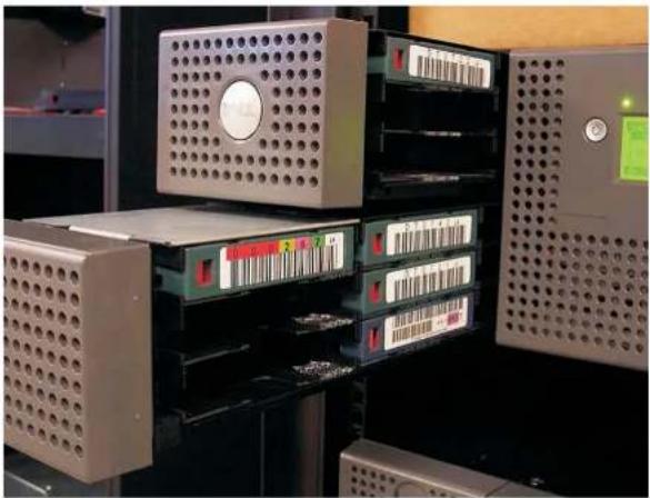
natural_image
Industrial rack with multiple storage units and a central control panel (no visible text or symbols)Figure10-23. Leftmagazinespulledoutofa4Ulibrary(facingfrontoflibrary)
- Insert the cartridge magazines removed from the defective library into the same positions in there replacement library enclosure.
- Insert the cartridge magazines removed from the replacement library enclosure into the same positions in the defective library to return to Dell.
- Waitforinventoryofthemagazinestocomplete.
a. If inventory is successful:
1) Thereplacementlibraryenclosurewillcompletewiththe
Ready/ActivityLED(1 in Figure10-20onpage10-22)ON
2)PowerOFFthereplacementlibraryenclosure.
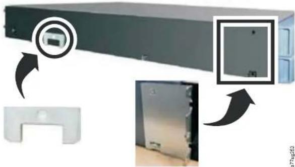
natural_image
Diagram showing a server rack with a close-up view of the front panel and its internal components, no text or symbols present.Figure 10-24. Mounting brackets and anchors for securing the library in a rack (one bracket and anchor one each side of the library)
- With assistance, slidethereplacementlibraryenclosureontothemetalrails that are already in position in the rack (see Figure 10-25).
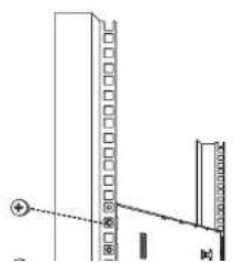
natural_image
Simple line drawing of a vertical structure with a horizontal beam and a force arrow, no text or symbols present.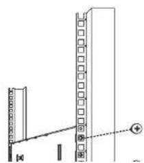
natural_image
Technical line drawing of a mechanical assembly with no visible text or symbolsDesktopInstallation:
-
Placethelibraryinitspermanentlocation.
-
Proceed to "Completing the Installation of the Replacement Library Enclosure."
CompletingtheInstallationoftheReplacementLibrary Enclosure
- Connectallcablestothereplacementlibraryenclosure.
2.PowerONthereplacementlibraryenclosure.
- Upgradelibraryfirmwareanddrivefirmwaretothelatestversion.
a. Visit http://www.support.dell.com/ to download the latest levels of library anddrivefirmware.
b. Using the Web User Interface (Service Library > Upgrade Firmware), upgradelibraryanddrivefirmware.
-
Run the Library Verify test (Operator Control Panel: Service > Library Verify). This diagnostic requires ablankorscratch data cartridge.
-
Proceed to "ReturningtheDefectiveLibraryEnclosure."
ReturningtheDefectiveLibraryEnclosure
-
Remove the shipping label (2) in Figure 10-15 on page 10-16 and lock (1) from therearpanelofthedefectivelibrary.placethelokintheslotlocatedinthetopcenterofthelibrary.andsecurewiththeshippinglocklabel.Thiswill securethelibraryaccessorforshipping.
-
Using thereplacement library enclosure packaging materials, securely package the defective library (including the left and right magazines, Library Controller Card, and powers supply removed from the placement library enclosure) and return to Dell.
Important: FailuretoreturnallofthesecomponentstoDellwillresultin youbeingchargedforanymissingcomponents.
AppendixA.SCSIElementTypes,SCSIAddresses,and PhysicalConfigurations
For an overview of library partitioning and element addressing, see "Library Partitioning and Element Addressing" on page A-3.
The following tables contain element addresses for the 2U library and the 4U library.
TableA-1.2UlibrarySCSIElementTypesandElementAddresses
| ElementTypeElementAddressRange | |
| MediaTransport(Accessor)Element(MTE)1(0x01) | |
| I/OStationElement(IEE)16(0x10) | |
| DataTransfer(Drvc)Element(DTE)256(0x100),257(0x101) | |
| StorageElements(STE)4096(0x1000)-4118(0x1016) | |
TableA-2.4UlibrarySCSIElementTypesandElementAddresses
| ElementTypeElementAddressRange | |
| MediaTransport(Accessor)Element(MTE)1(0x01) | |
| 1/OSstationElements(IEE)16(0x10),17(0x11),18(0x12) | |
| DataTransfer(Drives)Elements(DTE)256(0x100),257(0x101),258(0x102,259 (0x103) | |
| StorageElements(STE)4096(0x1000)-4140(0x102C) | |
2ULibrary/OSlot, StorageSlots and Drive Slot Element Addresses and Physical Locations
Foranoverviewoflibrarypartitioningandelementaddressing,see"Library PartitioningandElementAddressing"page 2.3
DTEassignments
•LogicalLibrary1:Drive1:256(0x100)
•LogicalLibrary2:Drive2:256(0x100)
STEassignments
•LogicalLibrary1:Slot1throughslot114096(x1000)through4106(0x100A)
•LogicalLibrary2:Slot12throughslot234096(x1000)through4107(0x100B)
TableA-3.2 LibrarySCS lelementaddresses for storageslots and driveslot (onological partition with onedrive)
| LeftMagazine Frontot2U.library | LibraryRearPanel | RightMagazineFrontot2Ulibrary | ||||||
| Slot84103(0x1007) | Slot94104(0x1008) | Slot104105(0x1009) | Slot114106(0x100A) | Drive1256(0x100) | Slot234118(0x1016) | Slot224117(0x1015) | Slot214116(0x1014) | Slot204115(0x1013) |
| Slot44099(0x1003) | Slot54100(0x1004) | Slot64101(0x1005) | Slot74102(0x1006) | Slot194114(0x1012) | Slot184113(0x1011) | Slot174112(0x1010) | Slot164111(0x100F) | |
| 1/Oslot16(0x10) | Slot14096(0x1000) | Slot24097(0x1001) | Slot34098(0x1002) | Slot154110(0x100F) | Slot144109(0x100D) | Slot134108(0x100C) | Slot124107(0x100B) | |
4ULibrary/OSlots, StorageSlots, and Drive Slots Element Addresses and Physical Locations
For an overview of library partitioning and element addressing, see "Library
PartitioningandElementAddressing"onpageA-3.
The following table contains the physical location (Slotx) and SCS element address in decimal (4xxx) and in hexadecimal (0x10xx) of the /O slots, storage slots, and drives slots in the 4 U library containing only two drives leds.
Inolder4UlibrarieswheretheDedicatedCleaningSlot(DCS)isinafixedlocation (slot9)andelectedtoberetainedasaDCS(optiontodeleteDCSisavailablein libraryfirmwaregreaterthan1.95) theaboveslotnumberingandelementaddress
TableA-4.4 LibrarySCSelementaddressesforstorageslotsanddriveslot(oneologicalpartitionwithdrivesinslot1andslot2)(continued)
| Slot184113(0x1011) | Slot194114(0x1012) | Slot204115(0x1013) | Slot214116(0x1014) | Drive2257(0x101) | Slot454140(0x102C) | Slot444139(0x102B) | Slot434138(0x102A) | Slot424137(0x1029) |
| Slot144109(0x100D) | Slot154110(0x100E) | Slot164111(0x100F) | Slot174112(0x1010) | Slot414136(0x1028) | Slot404135(0x1027) | Slot394134(0x1026) | Slot384133(0x1025) | |
| Slot104105(0x1009) | Slot114106(0x100A) | Slot124107(0x100B) | Slot134108(0x100C) | Slot374132(0x1024) | Slot364131(0x1023) | Slot354130(0x1022) | Slot344129(0x1021) | |
| LowerLeftMagazine | Drive1256(0x100) | LowerRightMagazine | ||||||
| I/OSlot318(0x12) | Slot74102(0x1006) | Slot84103(0x1007) | Slot94104(0x1008) | Slot334128(0x1020) | Slot324127(0x101F) | Slot314126(0x101E) | Slot304125(0x101D) | |
| I/OSlot217(0x11) | Slot44099(0x1003) | Slot54100(0x1004) | Slot64101(0x1005) | Slot294124(0x101C) | Slot284123(0x101B) | Slot274122(0x101A) | Slot264121(0x1019) | |
| I/OSlot116(0x10) | Slot14096(0x1000) | Slot24097(0x1001) | Slot34098(0x1002) | Slot254120(0x1018) | Slot244119(0x1017) | Slot234118(0x1016) | Slot224117(0x1015) | |
LibraryPartitioningandElementAddressing
Library4Usystemswithfirmwareversionsof.80andhigher,andcontainingat least2drives,havethcabilitytoconfiguretwologicallibraries(createtwo partitions).Thispartitioninghasbeenexpandedwiththenewlibrary firmware and half-highdriveintegration.Nowitispossibletoconfigure1,2,3or4partitionsin the4Ulibrary. Additionallythe2ULibrarycarnowbeconfiguredintooneortwo partitions.Eachlibrarymustcontainatcastonedrivecporlogicallibrary (partition).Inapartitionedlibrary,theOperatorControlPanel(OCP)onlyreports thestatusofologicallibrary1inthemainmenuductospacelimitations.Youmust navigateothelogicallibrariesstatusintheOCPtogettheinformationonthe additionallibrarypartitions.
thatusedtooccupytwo. Asaresult, thefirsthalfheightdriveposition, orthefirst full-highdriveposition, willbecalled "Drive1". Thesecondhalfheightdrive positionwillbecalled "Drive2". Thethirdhalfheightdriveposition, orthesecond fullheightdriveposition, willbecalled "Drive3". Thefourthhalfheightdrive positionwillbecalled "Drive4".
Important: Ina4 Ulibrary a full height drives led maybe be installed in driveslot1 (drivewilloccupyslot1 and slot2) or driveslot3 (drivewilloccupyslot3 and slot4). A full height drives led should never be installed in driveslot2 (drivewilloccupyslot2 and slot3).
MixingofDrives
The library will support amixoffullheightandhalfheightdrivesinthesame physicallibraryandthesamelogicalibrary. They will support amixofdrivesin the same physicallibraryandthesamelogicalibrary. They will also support amix of SCSLSAS, and Fibre Channelinthesamephysicallibrary and the samological library; however, mixing driveinterfacetypesinthesamelogicallibrary is not recommended.
Important: Drivesthatdonotshareacommmonmediatypecannotbemixed in the sameclogicalibrary.Forinstance, Gen3 and Gen6 drives cannot use the samemediaandsothey cannotbemixed. LTO3 mediacannot be readonLTO6drives.
Configurationofa1-PartitionSystem
Aonepartitionsystemconfiguredfora4Ulibrarycontainsanyandalldrives presentinanydrivepositions,anditwillcontainallfourmagazines.When configuredwithoncologicalpartition,theElementAddressassignmentswillbeas follows:DTEassignmentswillbeasshowninFigureA-1
STEassignments
•LogicalLibrary1:Slot1through234096(0x1000)through4118(0x1016)as showninFigureA-4onpageA-6
When configured with twological partitions, the Element Address assignments will be as follows: DTEassignments will be as shown in Figure A-2.
STEassignments
•LogicalLibrary1:Slot1throughslot214096(x1000)through4116(0x1014)
•LogicalLibrary2:Slot22throughslot454096(x1000)through4019(0x1017)
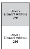
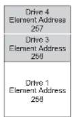
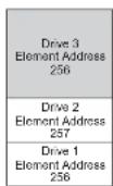
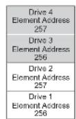
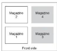
FigureA-2. Configuration of two-partitionsystem
Configurationofa3-PartitionSystem
Athreepartitionsystemmusthaveatleastthreedrivesinstalled. Adrivemustbe installeddriveposition1,anotherdrivevmustbinstalleddriveposition2, andanotherdrivevmustbeinstalleddeitherdriveposition3ordriveposition4. Partition1willcontainthefirstdriveandthefirstmagazine. Partition2will containtheseconddriveandthesecondmagazine. Partition3willcontainany drivesindriveposition3anddriveposition4. Partition3willalsocontain magazine3andmagazine4.
STEassignments
•LogicalLibrary1:Slot1throughslot94096(x1000)through4104(0x1008)
•LogicalLibrary2:Slot10throughslot214096(x1000)through4107(0x100B)
•LogicalLibrary3:Slot22throughslot454096(x1000)through4119(0x1017)
STEassignments
•LogicalLibrary1:Slot1throughslot94096(x1000)through4104(0x1008)
•LogicalLibrary2:Slot10throughslot214096(x1000)through4107(0x100B)
•LogicalLibrary3:Slot22throughslot334096(x1000)through4107(0x100B)
•LogicalLibrary4:Slot34throughslot454096(x1000)through4107(0x100B)
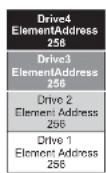
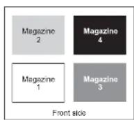
n77ug164
FigureA-4. Configuration of a four-partition system
SCSIElementAddressing
Every logical library starts at the first drives slot with the current assigned element start address (default value 256). It will be incremented from the bottom to the top slots forever drives slot. There is one exception to this addressings schemeto accommodates libraries currently in the field. A4 Ulibrary which contains only full height drives will continue to have the addresses assignments 256 and 257, thus causing no interruption to the operation. Drives slot will still be incremented by 1 before drives slot position.
Note: Exchanging drives with different form factors will result in the library needing to be reconfigured.
4U Unit with only FH drives
(1 logical library)

physicallyavailableortemporarilyremovedarereported.Empty(unused)slots locatedatthechottomorthetopsholnotbereported,withanexceptionincase o"removed"condition.Adriveslotwhichdoesnotcontainadrive,andhasa positionbetwencusedslots,necdstobereportedasACSlelement Tosignalthe hostapplicationthatthisslotisnotusable,itsACCESSbitwillbedisabled.
Note: When reducing the number of drives in your library, update the Logical Library configuration. This will remove the Attention LED on the front panel and the exclamation mark on the Iomescreen indicating that a drive is missing.
UpdatingtheLogicalLibraryconfigurationwillalsoupdatedthedriveelementaddressinganddrivenumbering,ReplacingLTOhalfheightdriveswithfullheightdrivesmayrequireyoutoexecuteRestoreFactoryDefaultstocorrectlyupdatethedriveelementaddressinganddrivenumbering. See"ConfigureLibrary: Save/RestoreConfiguration"onpage5-57.
AppendixB.TapeAlertFlags
Thisappendixisintendedtoprovideadditionalinformationtothereaderabout thetapeDrive.Allerrorcodeanddiagnosticinformationcontainedinthischapter canbeaccessedfromtheOperatorControlPaneloftheLibrary.Thedriveportion oftheOperatorControlPanelDisplaywillcontainanydriveerrorcodes. ThereforethereisnoneedtoopentheLibrarytoaccessthebuttonsonthedriveas describedinthischapter.
TapeAlertisastandardthatdefinesstatusconditionsandproblemsexperiencedby devicesuchastapedrives,autoloaders,andlibraries.Thestandardenablesa servertoreadTapeAlertmessages(calledflags)fromatapedriveviatheSCSibus. TheserverreadstheflagsfromLogSensePage0x2E.
ThislibraryiscompatiblewithTapeAlerttechnology,whichprovideserrorand diagnosticinformationaboutthcdrivesandthelibrarytothecser. Because library and drive firmware may change periodically,theSNMPinterfaceinthe librarydocsnotrequirecodechangesifdevicesaddadditionalTapeAlertsthatare notsupportedtoday.However,shouldthisoccurtheManagementInformation Block(MIB)iswrittentominimizeimpacttotheSNMPmonitoringstation.Atthe timeofthiswriting,theTapeAlertflagsinthisappendixcorrectlyrepresent TapeAlertsthatwillbesent.TheMIBfileshouldnotbetakentomeanthatall trapsthatadefinedintheMIB(refertoAppendixF,"SNMPStatusMIB VariablesandTraps,"onpageF-1)willbesentbythelibraryorthattheywillbe sentinthefuture.
ThisappendixlistsTapeAlertflagsthataresupportedbytheUltrium3,4,5,and6 TapeDrives.
TapeAlertFlagsSupportedbytheLibrary
Parameter Code
FlagnameTypeActionRequired
| 04dLibrary | HardwareD | C | •Ensure that the mediachanger and drives are not being used by any host, then reset the library from the front panel.• If the problem persists, contact technical support. |
| 13dLibraryPick | Retry | W Thereisapotential problem with the cartridge loader picking a cartridge from drive or slot.• No action needstobetaken at thistime.• If the problem persists, contact technical support.This flag is cleared when then next move command is received. | |
| 14dLibraryPlace | Retry | W Thereisapotential problem with the cartridge loader placing a cartridge into aslot.• No action needstobetaken at thistime.• If the problem persists, contact technical support.This flag is cleared when then next move command is received. | |
| 15dDriveLoad | Retry | W Thereisapotential problem with the cartridge loader driving when placing a cartridge into a drive.• No action needstobetaken at thistime.• If the problem persists, contact technical support.This flag is cleared when then next move command is received. | |
| 17dLibraryI/O | Station | CThercisamc mechanical problem with the library medial / O Station. | |
| 18dMedia | Changer | CItissetwhen am magazine is removed from the changer. | |
| 19dLibrary | Security | W library security has been compromised. Thedoor was opened then closed during operation. | |
| 21dMcdia | Changer | If tissct when the changcrissstoffline. | |
| 24dLibrary | Inventory | CThelibrary has detected an inconsistency in its inventory.• Redothelibrary inventory to correct inconsistency.• Restart the operation.Check the applications users manual or the hardware users manual for | |
TapeAlertFlagsSupportedbytheDrive
TableB-1. TapeAlertFlagsSupportedbytheUltriumTapeDrive
| Flag NumberFlagDescriptionActionRequired | |||
| 3HarderrorSetforanyunrecoverableread,write,orpositioningerror.(Thisflagissetin conjunctionwithflags4,5,or6.) | SectheActionRequiredcolumnfor FlagNumber4,5,or6inthistable. | ||
| 4MediaSetforanyunrecoverableread,write,orpositioningerrorthatisductoa faultytapecartridge. | Replacethetapecartridge. | ||
| 5ReadfailureSetforanyunrecoverablereaderrorwhereisolationisuncertainand failurecouldbeduetoafaultytape cartridgeortofaultydrivehardware. | IfFlag4isalsoset,thecartridgeis defective.Replaceethetape cartridge. | ||
| 6WritefailureSetforanyunrecoverablewritcoperpositioningerrorwhereisolationis uncertainandfailurecouldbedueto afaultytapecartridgeortofaulty drivehardware. | IfFlagNumber9isalsoset,makc surethathewrite-protectswitch issetothatdatacanbewrittento thetape(see"Write-ProtectSwitch" onpage6-6).IfFlagNumber4is alsoset,thecartridgeisdelective.Replaceethetapecartridge. | ||
| 7MedialifeSetwhenthetapecartridgercachesits endoflife(EOL). | 1.Copythedatatoanothertape cartridge.2.Discardthcold(EOL).tape. | ||
| 8Notdatagrade Setwhenthecartridgeisnot data-grade.Anydatathatyouwrite tothetapeisalrisk. | Replacethetapecwithadata-grade tape. | ||
| 9Writeprotect Setwhenthetapedrivedetectsthat thetapecartridgeiswrite-protected. | Ensurethatthccartridge's write-protectswitchissetsothat thetapedrivecanwritedatalothe tape(sce"Write-ProtectSwitch"on page6-6) | ||
| 10 Noremoval Setwhenthetapedrivereceivesan UNI OATCommandaftertheserver | Reertothedocumentationloryour server'soperatingsystem | ||
| Flag NumberFlagDescriptionActionRequired | |||
| 18Tapedirectorycorruptedinthecartridgememory | Setwhenthedrivedetectsthatthetapedirectoryinthecartridgememoryhasbencorrupted. | Re-readalldatalromthetapetorebuildthetapedirectory. | |
| 19\earingmedialifeSetwhenthetapecartridgeisnearingitsspecifiedendollide.Theflagisclearedwhenthecartridgesremovedfromthedrive. | 1.Copythedatatoanothertapecartridge.2.Replaceethetapecartridge. | ||
| 20CleannowSetwhenthetapedrivedetectsthatitneedsdcleaning. | Cleanthetapedrive. | ||
| 21CleanperiodicSetwhenthedrivedetectsthatitneedsroutinecleaning. | Cleanthetapedriveassoonaspossible.Thedrivecancontinuetooperate,butyoushouldcleanthedrivesoon. | ||
| 22ExpiredcleanSetwhenthetapedrivedetectsacleaningcartridgethathasexpired. | Replacehecleaningcartridge. | ||
| 23InvalidcleaningtapcSctwhenthedrivcexpectsackaningcartridgeandtheloadedcartridgeisnotacleuningcartridge. | Uscavalidcleaningcartridge. | ||
| 30HardwareASctwhenahardwarefailurcoccursthatrequiresthatyouresetthetapedrivetorecover. | |||
| 31HardwareB | SetwhenthetapedrivefailsitsinternalPower-OnSelfTests. | Notetheerrorcodeonthesingle-charactercardisplay,then | |
| 32Interface | Setwhenthetapedrivedetectsaproblemwiththehostinterface. | ||
| 33Ejcctmcdia | Sctwhenafailurccoursthatrequiresyoutounloadthecartridgefromthedrive. | Unloadthetapecartridge,thenreinsertitandrestarttheoperation. | |
| 34Downloadfail | SctwhenanFMRimagcisunsuccessfullydownloadedtothetapedrivethroughtthehostinterface. | EnsurethatitisthcorrectFMRimage.DownloadtheFMRimageagain. | |
| 53Tapesystemareareadfailure | Setwhenthetapesystemareacould notbereadsuccessfullyatloadtime. | Copythedatatoanothertape cartridge,thendiscardtheold cartridge. | |
| 55LoadingFailureWhenloadingatape | eintoadrive,ahardwaremalfunctioncanpreventthe tapefrombeingloadedintothedrive,orthetapemayactuallygetstuckin thedrive. | Takethisactionifthetapcartridge willnotloadinthedrive:1.Removcthetapcartridgefrom thelibraryandinspectifor damage.lfdamaged,discardit.2.Tryanothercartridgeinthat tapedrive.Iftstillails,replace thedrivesled See"Removing/Installing/Adding TapeDriveSled"onpage10-3.Takethisactionifthetacisstuck inthedrive:1.Attempttounloadthetapefrom thedriveusingthehostbackup applicationthatiscurrently usingthedrive,orusingthe remoteorlocalU.1.Ifthecartridgewillnotunload, contacttechnicalsupport. | |
| 56UnloadFailureWhenattemptingto | unloadatape cartridge,adrivehardware malfunctioncanpreventthetapefrom beingejected.Thetapemayactually bestuckinthedrive. | 1.Unloadthecartridgefromthe driveusingtheOperatorControl Panel(Control>Move Cartridge)ortheWebUser Interface(ManageLibrary>MoveMedia).2.Cycledrivepowerusingthe OperatorControlPanel(Service >Service>DrivePower) or the WebUserInterface(Configure Library>Drive) | |
AppendixC.SenseData
Whenadriveencountersanerror,itmakessensedataavailable.Youcanuse devicedriverstocxaminthesensdataanddeterminerrors.Thedevicedrivers mayconflictwithsomecommercialsoftwareapplicationsunlessproperly configured.ToavoidconflictsonWindowsoperatingsystems,refertoyourdevice driver sproceduresforsettingthedrivertomanualstartupmode.
If your application uses other devices, seethe appropriate documentation forthos driversto obtain the sensor data.
In addition to device drivers, other method sexist for obtaining data and error information. These section that follows describe alternatives for gathering such information.
Librara sensedata
The following table lists the AdditionalSenseCodes(ASC) and AdditionalSense CodeQualifiers(ASCQ) associated with thereportedSenseKeys.
Asensekeyof00h(nosense)hasnoASC/ASCQassociatedwithit.Afew ASC/ASCQsarcassociatedwithmorethanoncsensekey. Thesensckeysthat givesparticularASC/ASCQsareindicatedwithintheSenseKeycolumn. ASC/ASCQscanindicatecanabnormalelementstatcaspartofclementdescriptor.
TableC-1.LibrarySenseKeys,ASCandASCQ
| SenseKeyASCASCQDescription | |||
| RecoveredError(01)0Ah00hErrorlogoverflow | |||
| 47h00hSCSParityerror | |||
| NotReady(02)00h17hDrivecleaningrequested | |||
| 04h00hCausenotreportable | |||
| 04h01hImprogressbycomingready scanningamazazines etc | |||
| MediumError(03)30h10hIncompatible | mediainstalled | ||
| 30h03hCleaningtapeinstalled | |||
| 30h07hCleaningfailure | |||
| HardwareError(04)81h80h | Cannotinitializebarcodereader | ||
| 81h81hNoresponsefrombarcodereader | |||
| 81h82hNorresponsefromEEPROM | |||
| 81h83hSlaveroboticgenericproblem | |||
| 81h84hSettingofgripperpicvaluelailed | |||
| 81h85hSettingofsliderpicvalucafailed | |||
| 81h86hSettingofelevatorpicvaluefailed | |||
| 81h87hSettingofrotaionpicvaluefailed | |||
| 81h88hSettingofslcdpicvalucafailed | |||
| 81h89hGripperblocked | |||
| 81h8AhSliderblocked | |||
| 81h8BhElevatorblocked | |||
| 81h8ChRotationblocked | |||
| 81h8DhSlcdblocked | |||
| 81h8EhCannotfindgripperblock | |||
| 81h8FhCannotfindsliderblock | |||
| 81h90hCannotfindelevatorblock | |||
| 81h91hCannotfindrotationblock | |||
| 81h92hCannotfindslcdblock | |||
| 81h93hGripperoutsiderange | |||
| 81h94hSlideroutsiderange | |||
| 81h95hElevatoroutsiderange | |||
| 81h96hRotationoutsiderange | |||
| 81h97hSlcdoutsiderange | |||
| 81h98hNocartridgespresentscensorfound | |||
| HardwareError(04)(continued) | 81hB0hSlaveroboticcontrollerresponsetimeout | ||
| 81hB1hNACKreceivedfromslaveroboticcontroller | |||
| 81hB2hSlaveroboticcontrollercommunicationfailed | |||
| 81hB3hSlaveroboticcontrollerurgentstop | |||
| 81hB4hCartridgesidnottransportcompletely | |||
| 81hB5hSlaveroboticcontrollerdocsnotrespondoncommand | |||
| 80hC0hNetworkinit | |||
| 80hC1hTeinetinterface | |||
| 80hC2hWebserver | |||
| 80hC3hEEPROMparameter | |||
| 80hC4hCannotinitLANcard | |||
| 80hC5hWritetoEEPROMfailed | |||
| 80hC6hPingcommanddidnotreachtarget | |||
| 80hC7hCannotupgradefromUSB | |||
| 80hC9hCannotUpgradeRoboticfromFlash | |||
| 80hD0hROMerror | |||
| 80hD1hRAMerror | |||
| 80hD2hNVRAMerror | |||
| 80hD3hCTCerror | |||
| 80hD4hUARTerror | |||
| 80hD5hDssplayererror | |||
| 80hD6hMemoryerror | |||
| 80hD7hFatalsystemerror | |||
| 80hD8udBaseerror | |||
| 80hD9hNpSCSIIcdetected | |||
| HardwareError(04)(continued) | 82hF4hDriveloadtimeout | ||
| 82hF5hDriveunloadtimeout | |||
| 82hF6hDriveneverpresent | |||
| 82hF7hDrivesupportticketeteror | |||
| 82hF8hDriveinvalidcommand | |||
| 82hF9hDriveinvalidparameter | |||
| 82hFAhSDCImicrocoderror | |||
| 82hFBhDrivelloggedout | |||
| 82hFChInternaldrivecommandfailedwithCheckCondition | |||
| 82hFDhlInternaldrivecommandtimeout | |||
TableC-1.LibrarySenseKeys,ASCandASCQ(continued)
| SenseKeyASCASCQDescription | ||||
| IllegalRequest(05h)1Ah00hParameterlengtherror | ||||
| 20h00hInvalidcommandoperationcode | ||||
| 21h01h | •Invalidelementaddress-associatedwithErrorCode33•Invaliddrivespecified-associatedwithErrorCode35 | |||
| 24h00h | •InvalidfieldintheCDB-associatedwithErrorCode34•SENDDIAGInvalidtestnumber-associatedwithErrorCode36 | |||
| 3Dh00hSCSlinvalidIDmessage | ||||
| 25h00hInvalidLUN | ||||
| 2Ch00hCommandsequenceerror | ||||
| 26h00hInvalidfieldinparameterlist | ||||
| 26h01hParameterlisterror:paramctcrnotsupported | ||||
| 26h02hParametervalueinvalid | ||||
| 26h90hWrongfirmwareimage,doesnotlitbootcode | ||||
| 26h91hWrongpersonalityfirmwarcimage | ||||
| 26h93hWrongfirmwareimage,checksumerror | ||||
| 30h12hIncompatiblemedium | ||||
| 39h00hSavingparametersnotsupported | ||||
| 3Bh0DhMediumdestinationelementfull | ||||
| 3Bh0EhMediumsourceelementempty | ||||
| 3Bh11hMediummagazincnotaccessible | ||||
| 3Bh81hMediumbelongstoanotherpartition | ||||
| 3BhA0hMediumtransierelementfull | ||||
| 53h02hLibrarymediaremovalpreventedstateset | ||||
| 53h03hDrivemediamaremovalpreventedstateset | ||||
| 44h80hBadstatuslibrarycontroller | ||||
TableC-1.LibrarySenseKeys,ASCandASCQ(continued)
| SenseKeyASCASCQDescription | |||
| UnitAttention(06h)28h00h | Notreadytoreadytransition | ||
| 28h01hImport/exportelementaccessed | |||
| 29h01hPoweronoccurred | |||
| 29h02hSCSIBusresectccurred | |||
| 29h05hBustypechangedtoSingleEnded(SE) | |||
| 29h06hBustypechangedtoLowVoltageDifferential(LVD) | |||
| 2Ah01hModeparameterschanged | |||
| 2Ah10hTimestampchanged | |||
| 3Bh13hMediummagazincinserted | |||
| 3Fh01hMicrocodehaschanged | |||
| 53h02hMediaremovalprevented | |||
| CommandAborted(0Bh)3Fh0FhECHObufferoverwritten | |||
DriveSenseData
LTOUltrium4drivescontainhardwarewhichperformsuserdatawriteencryption andreaddecryption,protectingalluserdatawrittentothemediumfrom unauthorizeduse,provideditisintegratedintoasecuresystemdesign.
TableC-2.LTOTapeDriveSenseData
| Byte | BitAddressorName | |||||||
| 7 | 6 | 5 | 4 | 3 | 2 | 1 | 0 | |
| Address | ||||||||
| 2FilemarkEOM(end | ofmedium) | IL1 (Incorrect length indicator) | ReservedSense | KeyDescription | ||||
| 0-Nosense | ||||||||
| 1-Recoverederror | ||||||||
| 2-Notready | ||||||||
| 3-Mediaerror | ||||||||
| 4-Hardwarcerror | ||||||||
| 5-Illegalrequest | ||||||||
| 6-Unitattention | ||||||||
| 7-Dataprotect | ||||||||
| 8-BlankCheck | ||||||||
| 9-Reserved | ||||||||
| A-Reserved | ||||||||
| B-Abortedcommand | ||||||||
| C-Reserved | ||||||||
| D-Volumeoverflow | ||||||||
| E-Reserved | ||||||||
| F-Reserved | ||||||||
| 3Informationbyte(mostsignificantbyte) | ||||||||
| 4Informationbyte | ||||||||
| 5Informationbyte | ||||||||
| 6Informationbyte(leastsignificantbyte) | ||||||||
| 7AdditionalSenseLength | ||||||||
| 8-11Commandspecificinformation | ||||||||
| 12-13AdditionalSenseCode(ASC)AdditionalSenseCodeQualifier(ASCQ)Byte12Byte13ASCASCQ0000-Noadditionalsense-Theflagsinthesensedataindicatethereasonforthccommandfailure0001-Filemarkdetected-AReadorSpacecommandterminatedearlyduetoanFAMTheFMflagisset.0002-EOM-AWriterWriteFileMarkscommandfailedbecausethephysicalendoftapewasencountered,oraReaderSpacecommandencounteredEOMTheEOMflagisset0004-BOM-AspacecommandendedatBeginningofTapeTheEOMbitisalsoset0005-FOD-ReadorSpacecommandterminatedearlybecauseEndoIDatawasencountered0016-OperationinProgress0400-Causenotreportable-Acartridgeispresentinthedrive,butitisintheprocessolbeingunloaded0401-BecomingReady-Amediaaccesscommandwasreceivedduringafrontpanelinitiatedloadoranimmediaterportedloadcommand0402-InitializingCommandRequired-Acartridgeispresentinthedrive,butisnotlogicallyloaded.ALoadcommandisrequired0403-ManualInterventionRequired-Acartridgeispresentinthedrivebutcouldnotbcloadedorunloadedwithoutmanualintervention0410-Logicalunitnotready,auxiliarymemorynotaccessible0412-Logicalunitnotready.offline0801-Logicalunitcommunicationfailure0900-Trackfollowingerror(servro)0C00-WriteError-AWriteoperationhaslailed.Thisisprobablyduetobadmedia,butmaybehardwarerelated1100-UnrecoveredReadError-AReadoperationfailed.Thisisprobablyduetobadmedia,butmaybehardwarerelated1112-Auxiliarymemoryreadererror.ThedriverreportedthatitisunabletoreadtheAuxiliaryMemoryaWORMcartridge.1400-RecordedEntityNofound-Aspaceort.ocatecommandfailedbecause | ||||||||
| 12-13AdditionalSenseCode(ASC)-AdditionalSenseCodeQualifier(ASCQ)(Continued)Byte12Byte13ASCASCQ2700-WriteProtect-AWritetypeoperationhasbeenrequestedonacartridgewhichhasbeenwriteprotected2800-NotReadytoReadyTransition-Acartridgehasbeenloadedsuccessfullyintothedriveandisnowreadytobeaccessed2801-Importorexportelementaccessed2900-Reset-Thedrivehaspowercedon,receivedaresetsignalorabusdeviceresetsignalsincetheinitiatorlastaccessedit2904-Deviceinternalreset2A01-ModeParametersChanged-TheModeparametersforthedrivechavebeenchangedbyaninitiatorotherthantheoneissuingthecommand2C00-Comunandsequenceerror2C0B-Notreserved-TheOfRbitofthesequentialaccessdevicepageissetandthel-Inexusattemptingtocommunicatewiththedrivedoesnotholdareservation.2F00-Commandsclearedbyanotherinitiator3000-IncompatibleMediaInstalled-Awritetypeoperationcouldnotbeexecutedbecauseitisnotsupportedonthecartridgetypethatisloaded.3001-UnknownFormat-Anoperationcouldnotbecarriedoutbecausethecartridgeinthedriveisofaformatnotsupportedbythedrive3002-IncompatibleFormat-AnoperationcouldnotbecompletedbecausetheLogicalFormatisnotcorrect3003-CleaningCartridgeInstalled-Anoperationcouldnotbecarriedoutbecausethecartridgeinthedriveisacleaningcartridge3005-Cannotwritemedium,incompatibleformat3007-CleaningFailure-Acleaningoperationwasattempted,butcouldnnotbecompleteddforsomcreason300C-DataProtect-WORMoverwriteattempted.Thedriverejectedadwritecooperationbecauseitwouldhaveresultedinanoverwrite.OverwriteisnotallowedonWORMmedia.300D-MediumError-WORMintegritycheck.ThedriverejectedaReaderWriterooperationbecausethecartridgegeisasuspiciousWORMcartridge. | ||||||||
| 12-13AdditionalSenseCode(ASC)-AdditionalSenseCodeQualifier(ASCQ)(Continued)Byte12Byte13ASCASCQ4100-Datapathfailure4300-MessageError-Ammessagecouldnotbescentorreceivedduetoexcessive transmissionerrors4400-Internaltargetfailure-Ahardwarefailurehasbeendetectedinthedrive thathascausedthecommandtofail4500-Select/ResetFailure-Anattempttoreselectaninitiatorinorderto completethecommandhasailed4800-Initiatordetectederrormessagereceived4900-Invalidmessagerror4A00-Commandphaseerror4B00-DataPhaseError-Acommandcouldnotbecompletedbcausetoomany parityerrorsoccurredduringtheDataphasc4F00-OverlappedCommands-Aninitiatorselectedthedriveeventhought alareyhadacommandoutstandinginthedrive5000-WriteAppendError-Awritetypecommandfailedbcecausethcpointat whichtoappenddatawasunreadable5100-Erasefailure-AnErasecommandfailedtoerasetherequiredareaonthe media5200-Cartridgefault-Acommandcouldnotbecompletedduetoafaultinth tepeccartridge5300-MediaLoad/EjectFailed-(SenseKey03)Anattempttoloadoreject thecartridgefailedduetoaproblemwiththecartridge.5300-MediaLoad/EjectFailed-(SenseKey04)Anattempttoloadoreject thecartridgefailedduetoaproblemwiththedrive5302-MediaRemovalPrevented-AnUnloadcommandhaslailedtoejectthe cartridgebcecausedmediaremovalhasbeenprevented5A01-Operatormediumremovalrequest5D00-FailurePredictionThreshold-FailurePredictionthresholdshavebeen exceededindicatingthatafailuremayoccursoon5DFF-FailurePredictionFalse-AModeSelectcommandhasbeenusedtotest forfailurePredictionsystem. | ||||||||
| 12-13AdditionalSenseCode(ASC)-AdditionalSenseCodeQualifier(ASCQ)(Continued)Byte12Byte13ASCASCQSenseKey0(NoSense)EF13-Encryption-KeyTranslateEF13-Encryption-KeyTranslateEKMSenseKey3(MediumError)3002-Encryption-Encryption/featureisnotenabledsotormat/processingisnotsupportedEE60-Encryption-ProxyCommandErrorEED0-Encryption-DataReadDecryptionFailureEED1-Encryption-DataReadafterWriteDecryptionFailureEEE0-Encryption-KeyTranslationFailureEEE1-Encryption-KeyTranslationAmbiguousEEF0-Encryption-DecryptionFenced(Read)EEF1-Encryption-EncryptionFenced(Write)SenseKey4(HardwareError)EE0E-Encryption-KeyServiceTimeoutEE0F-Encryption-KeyServiceFailure4000-Encryption-FailureHardware,POSTorModuleFailureSenseKey5(IllegalRequest)EE00-Encryption-KeyServiceNotEnabledEE01-Encryption-KeyServiceNotConfiguredEE02-Encryption-KeyServiceNotAvailableEE10-Encryption-KeyRequiredEE20-Encryption-KeyCountExceededEE21-Encryption-KeyAliasExceededEE22-Encryption-KeyReservedEE23-Encryption-KeyConflictEE24-Encryption-KeyMethodChangeEE25-Encryption-KeyFormatNotSupported | ||||||||
| 12-13SenseKey6(UnitAttention)EE12-Encryption-KeyChangeDetectedEE18-Encryption-Changed(Read)EE19-Encryption-Changed(Write)EE40-Encryption-EKMIdentifierChangedEE41-Encryption-EKMChallengeChangedEE50-Encryption-InitiatorIdentifierChangedEE51-Encryption-InitiatorResponseChanged2A11-Encryption-DataEncryptionParametersChangedbyAnotherITNexus2A12-Encryption-DataEncryptionParametersChangedbyVendorSpecificEventSenseKey7(DataProtect)EF10-Encryption-KeyRequiredEF11-Encryption-KeyGenerationET13-Encryption-KeyTranslateEF1A-Encryption-KeyOptionalEFC0-Encryption-NoOperation2610-Encryption-DataDecryptionKeyFailLimit2A13-Encryption-DataEncryptionKeyInstanceCounterHasChanged7400-SecurityError7401-Encryption-UnabletoDecryptData7402-Encryption-UnencryptedDataEncounteredWhileDecrypting7403-Encryption-IncorrectDataEncryptionKey7404-Encryption-CryptographicIntegrityValidationFailed7405-Encryption-ErrorDecryptingData | ||||||||
| 14FRUcode | ||||||||
| 15SKSVC/DReservcdBPV | Whensetto1,thebitpointerisvalid. | Bitpointer | ||||||
| 16-17SKSV=0:FirstErrorFaultSymptomCode(FSC).SKSV=1:FieldPointer | ||||||||
| 36-39PortIdentifier(RelativeTargetPortAddress)ReportingSense(Thisistheportaddressofthedriveportthroughwhichscnscisbeingreported.OnFibreChanneldrives,itistheFibreChannelFabricPortAddress[forexample,011E13or000026]withbyte36beingreserved.OnSASdrives,itistheHashedSASAddressofthedriveport[forexample,F32A94]withbyte36beingreserved.OnSCSI,bytc36through38arcreservcd,andbyte39isscttuthcport'sSCSIaddress[i.c.,byte39-byte34].) | ||||||||
| 40Tape | DirectoryValid | ReservedReservedReservedReservedRelativeTgtPortReportingSense0:Reserved1:RclativcTgtPort1(Port0)2:RclativcTgtPort2(Port1)3:RelativcIgtPort3(LibraryPort) | ||||||
| 41HostCommand(SCSIOpcode) | ||||||||
| 42DensityType0:Nomcdiaprescnt1:Gen1(384track)2:Gen2(512track)3:Gen3(701track) | MediaTypc(VendorReserved) | |||||||
| 43 | VolumeLabelCartridgeType | |||||||
| 44 | ||||||||
| 45-48LogicalBlockNumber(Current1.BAthatwouldherenportedinReadPositioncommand) | ||||||||
| 65 | LastErrorPSC | |||||||
| 66 | ||||||||
| 67 | LastErrorFlagData | |||||||
| 68 | ||||||||
| 69LPOSRegion | ||||||||
| 70-85ERPSummaryInformation | ||||||||
| 86-89ProductRevisionLevel:YMDV(asdefinedinStandardInquiry;thisisalsoknownastheCodeLevel) | ||||||||
| 90-95Rescerved(0) | ||||||||
The descriptions below serve only as an overview of the reporting in the tape drive. This tape drive conform to all sense field reporting as specified in the SCSI standards.
Note:
- TheErrorCodefield(Byte0)issetto70htoindicateacurrenterror, thatisoncassociatedwiththemostrecentlyreceivedcommand.Itis setto71htoindicateadeferrederrorwhichisnotassociatedwith the currentcommand.
- Thesegmentnumber(Byte1)iszerosincetheCopy,Compare,and CopyandVerifycommandsarenotsupported.
- TheFileMarkflag(Byte2, bit7)issetifaSpace, Read, or Verify commanddidnotcompletebecauseafilemarkwasread.
- The End of Media (EOM) flag (Byte2, bit6) is set to Write File Marks command completed in the early warning area. Spacing into BOM also causes this flag to be set. It is also set on an attempt to read or spaccpast EOD, or fan attentionism and stop to begin of
meansthatthecurrentdirectionisawayfromthephysicalbeginningof thetape. A1 meansthatthecurrentdirectionistowardsthephysical beginningofthetape.
- Relative LPOS fields (Bytes30-33) report the current physical position on the tape.
13.SCSIAddressfield(Byte34) reports the SCSIBusAddressforthedrive. Values returned range from 00hto0Fh. - Thisfield(Byte35) contains the frame and driven number, passed across the RS-422 serial interface.
AppendixD.EnablingLUNSupportinLinux
Toverify the detection of ataped drive, administrator should check for its entry in /proc/scsi/scsi.Current versions of linux may not scan the logical storage unit (LUN) I do every device. This can result in some TL2000 / TL4000 devices not being identified or listed in the /proc/scsi/scsi output. Administrators can follow these step to enable support for such devices.
-
Type cat /proc/scsi/scsi. The output will look similar to the following: Attached devices: Host: scsi0 Channel: 00 Id: 01 Lun: 00 Vendor: IBM Model: ULT3580-HH3 Rev: 88M3 Type: Sequential-Access ANSI SCSI revision: 03
-
Identify the host adapter, channel number, target ID number, and LUN number for the first LUN of the device to be configured. In this example, the IBM Model ULT3580 (drive in the TL200) /TL4000 is shown at the address, or nexus, 0 0 0 0 — which means host adapter, channel number, ID1, and LUN0. The TL200 /TL4000 always shasthetaped drivcat LUN0 and therobot at LUN1.
-
ForeachLUNthatneedstobediscovered by Linux, issuethe following command: echo "scsi-add-single-deviceHCIL">/proc/scsi/scsi HCIL referstothenexusdescribedinstep2.So, withtheTL2000/T1.4000robot configuredatl.UN1,type:echo "scsi-add-single-device001 0">/proc/scsi/scsi.Theechocommandwillforceascanofeachdeviceatthe givennexus.
-
Type cat /proc/scsi/scsi again to verify that all devices are now listed. The outputwilllooksimilartothefollowing: Attached devices: Host: scsi0 Channel: 00 Id: 01 Lun: 00 Vendor: IBM Model: ULT3580-HM3 Rev: 80M3 Type: Sequential-Access ANSI SCSI revision: 03 Attached devices: Host: scsi0 Channel: 00 Id: 02 Lun: 01 Vendor: IBM Model: 3573-TL Rev: 7.10
RedHatEnterpriseLinux
RHELdoesn'tautomaticallyprobeallLUNsonSCSIdevices.Thesymptomshows 1.UN0,whichwouldbethedrive,butnottheloader.
- Type#cat /proc/scsi/scsi.
Attached devices:
Host: scsi0 Channel: 00 Id: 06 Lun: 00
Vendor: IBM Model: ULT3580-HH3 Rev: 88M3
Type: Sequential-Access ANSI SCSI revision: 03
- You will need to add the following to /etc/modules.conf options scsi_mod max_scsi_luns=255
Note: InRHEL4, it is max_luns = 255
- Oncethat sadded, youwillhavetorebuildtheinitrdandreboottheserver. Thereisawaytotestthisbeforeeditingthefilesandrebooting.butthere'stoo muchofariskoftakingdownotherSCSdevicesintheprocess.Rebuilding theinitrdwillbethetrickypart.Youhavetoknowexactlywhichkernel versionyouwanttousetodothisproperly.Youcanfindoutthekernelversion byusingtheunamecommand.
uname -r
2.4.9-e.38
Note: ThereisalistofknownkernelversionsontheRedHatEnterpriseLinux page.
4.So,giventheversionis2.4.9-e.38
# cp /boot/initrd-2.4.9-e.38.img /boot/initrd-2.4.9-e.38.img.bak
# mkinitrd -f -v /boot/initrd-2.4.9-e.38.img 2.4.9-e.38
This should give some output, then go to anew prompt. If it gives any errors, check the syntax you put into /etc/modules.conf or contacts someone knowledgeable with Linux.
- If successful, the server Will need to be rebooted. Once it comes backup, check / proc / scsi / scsi again.
cat /proc/scsi/scsi
Attached devices:
5.Addthe/LUNSswitchtotheloadlincoftheappropriateSCSIdriver.Ifadual channelcardisinstalledandyouareunsurewhichchanneltheLUNdeviceis attachedo,simplyeditbothlines. LOADADPT160M.HAMSLOT=201/LUNS LOADADPT160M.HAMSLOT=202/LUNS
-
After the STARTUP.NCF file has been edited, save the file and reboot the server to activate thenew STARTUP.NCF.
-
Upon reboot navigate to the System Console and type scan all. This will start ascanofalltheLUNSoneachadapter.
-
When the scan is complete, verify the Linux device has been detected using the list storage adapters command. Typical output with both the tape drive and loader being recognized: 0x08 [V321-A3] Adaptec SCSI Card 39160/39600 - Ultra160 SCSI [slot 201] 0x16 [V321-A3-D5:1] DELL PV-124T 0931 0x15 [V321-A3-D5:0] IBM ULT3580-TD3 5BG2 0x09 [V321-A4] Adaptec SCSI Card 39160/39600 - Ultra160 SCSI [slot 202]
Netwaremaydisplayunbounddevice,meaningadriverisnotboundtothe loaderunlessadriverfromabackupsoftwareisloaded. Thisdoesnotprevent thebackupapplicationfromdetectingtheLUNandbindingtheappropriate driver.
Note: The command scan all must be typed upon OS boot every time. If backup software services automatically start on OS boot, you must disable them, run the scan all command, and re-enable the services.
AppendixE.NotesonIPv6CompatibilitywithWindows 2003/XPand2008/Vista
IPv6addressingisdifferentfromtraditionalIPv4addressing. IPv4addressingis listedintheformat255.255.255.255, witeachvalue1byte, atotaladdressof4 bytes. IPv6addressesrequire16bytes, andarelistedintheformat FFFF: FFFF: FFFF: FFFF: FFFF: FFFF: FFFF: wherethereare8segmentseach2 byteslong.
Windows2003/XP
IPv6supportinWindows2003isnotturnedonbydefault. Usethefollowing instructionstoenableIPv6support.
- Go to Control Panel > Network Connections, and right-click on the Local Area ConnectioninterfacethatistobecenabledwithIPv6support.
- Select Properties from the drop-down menu, and the Local Area Connection Propertieswindowshouldopen.ClickontheInstallbutton.
- In the new Select Network Component Type window, select Protocol and click ontheAddbutton.
- In the Select Network Protocol window, select Microsoft TCP/IP version 6 and clickontheOKbutton.IPv6isnowenabled.
Windows2003andXPcomeswithaWinINetAPIthatdoesnotfullysupportIPv6 literals. UpgradingtoInternet Explorer7inWindows2003isrecommendedfor IPv6browsersupportastheWinINetAPIisupdatedwiththeinstallationof Internet Explorer7. Thirdpartybrowsers(suchasFirefox)alsousetheWinInet APIeitherdirectlyorindirectly,soanupgradetoIE7willberecommendedforall users.
As multipleIPv6addressescanbeassociatedwithonephysicalinterface,Windows 2003andXPuseaninterfacenumberassociatedwitheachlink-localIPv6address thatmustbeincludedforconnectivitytoanylink-localIPv6address.Theinterface
• AfterupgradingtheWinInetAPI(byupgradingtoIE7), the library RMU can be accessed from the browser by using the following format.
-Replaceall:with-.
-Appends
-Forexample,ifthelIPv6addressisfe80::1234:5678:abcandtheinterface number is 13, the address to browse to would be http://fe80--1234-5678-abcs13.ipv6-literal.net.
•UsingthesameIPv6addressasabove,anotheralternativetothiswouldbetocditthcostsfileinthc<WindowsBaseDirectory\system32\drivers\etc\directoryandaddthefollowingline:fe80::1234:5678:abc%13
-TheaddressstobrowsewouldbeHYPERLINK"http://%3hostname%3e/
"http://
-NotethattheinterfacenumbercanchangewitharebootoftheWindows host.
Windows2008/Vista
Windows2008andVistanativelysupportIPv6. Also,interfacenumbershavebeen removedfromtheseversionsofWindows. Allthatisneededtobrowsetoan addresswouldbetoaddbrackets(I)aroundtheIPv6address. Thus,ifthe TL2000/4000 IPv6 address is fe80::1234:5678:abc] intothebrowserwindow. Thisisapplicableforbothlink-localandglobalunicast IPv6addresses.
NotesonIPv6CompatibilitywithLinux
-
WhileIPv6issupportedunderlinux,IPv6literalsforlink-localaddressesare notcurrentlysupportedinLinuxbrowsers,sotheRMUwillnotbeaccessible inLinuxviaalink-localIPv6address.GlobalunicastIPv6addressesare supportedinthesamemannerasinWindows2008/Vistabrowsers.
-
The RMU is accessible through IPv4.
AppendixF.SNMPStatusMIBVariablesandTraps
Note: For additional information, refer to "SNMP Messaging" on page 1-7.
TableF-1.SNMPStatusEvents
| EventTrapIDDefinition | ||
| ColdStart0Libraryhasrcbooted. | ||
| StatusChange1Librarystatushaschanged. | ||
| DoorOpen2Librarydoorhasbeenopened. | ||
| MailSlotAccessed3Library1/OStationhasbeen | accessed. | |
| FaultPosted4Libraryhaspostedahardfault/error. | ||
| RequestDriveClean | 5Drivechasrequestedaclean. | |
| DriveError | 6Drivehasreportedanerror. | |
| LoaderRetriesExcessive | 7Libraryhasreportedexcessiveload | metrics. |
| LoaderOK | 8 libraryhasresumednormal | operations. |
| AccountPasswordChange | 9Accountpasswordinthelibraryhas | changed. |
| Note:TrapID9requireslibraryfirmwarelevel8.0orgreater,andthelatestSNMPMIBile. | ||
| ConfigurationChange | 10 | Libraryordriveconfigurationhas changed. |
| Library Login | 11 | Someone has logged into the library viatheWebUserInterface. |
| LibraryLogout | 12 | Somconchasloggedoutofthe libraryviatheWebUserInterface. |
| Note: Trap IDs 10, 11, and 12 require library firmware level 9.00 or greater and the latest SNMP MIB file. | ||
AppendixG.LibraryConfigurationForm
Use this form when planning your library configuration. Keep this document in secure location and update it when changes are made to the library configuration.
| GeneralInformation | ||||
| LibrarytypeTL2000TL4000 | ||||
| LibrarySerial Number | ||||
| Libraryname | ||||
| I/OStationEnabled | Disabled | |||
| AutoCleanEnabled | Disabled | |||
| LibraryNetworkSettings | ||||
| DHCPEnabledDisabled | ||||
| IPAddress | ||||
| Netmask Address | ||||
| Gateway Address | ||||
| DNSServersIP Addresses | ||||
| EKMServersIP Addresses | ||||
| Encryption Settings | ||||
| LogicalLibraries | ||||
| Numberin library | 1 | 2 | 3 | 4 |
| ModeRandom:ON/OFF | Random:ON/OFF | Random:ON/OFF | Random:ON/OFF | |
| Drivetypes4UPosition4:4UPosition3:2U/4UPosition2:2U/4UPosition1: | 4UPosition4:4UPosition3:2U/4UPosition2:2U/4UPosition1: | 4UPosition4:4UPosition4:4UPosition3:2U/4UPosition2:2U/4UPosition1:4UPosition3:2U/4UPosition2:2U/4UPosition1: | 4UPosition4:4UPosition3:2U/4UPosition2:2U/4UPosition1:4UPosition1: | |
| FibreChannel Drivesettings | LogicalLibrary:Position:Speed:Porttype:LoopID: | LogicalLibrary:Position:Speed:Porttype:LoopID: | LogicalLibrary:Position:Speed:Porttype:LoopID: | |
| SASDrive settings | LogicalLibrary:Position:ID: | LogicalLibrary:Position:ID: | LogicalLibrary:Position:ID: | |
| SCSIDrive settings | LogicalLibrary:Position:ID: | LogicalLibrary:Position:ID: | LogicalLibrary:Position:ID: | |
| User Accounts | ||||
| Role:Password: | ||||
| Role:Password: | ||||
| Role:Password: | ||||
| Role:Password: | ||||
AppendixH.Accessibility
Accessibilityfeatureshelpauserwhohasaphysicaldisability,suchasrestricted mobilityorlimitedvision,tousethcHTMLversionofthecustomer documentationsuccessfully.
Features
ThemajoraccessibilityfeaturesfortheHTMLversionofthisdocumentare:
• You can use screen-readersoftware and digital speech synthesis to hear what is displayed on the screen. The following screen readers are tested: WebKing and Window-Eyes.
- Youcanoperateallfeatureswiththekeyboardinsteadofthemouse.
Navigatingbykeyboard
Youcanusekeysorkeycombinationstocompleteoperationsandinitiatemany menuactionsthatarcalosodonethroughmouseactions.Youcannavigatethe HTMLversionoftheDellPowerVaultTL2000TapeLibraryandTL4000TapeLibraryUser'sGuidehelpsystemfromthekeyboardwiththefollowingkeycombinations:
- Totraversetothenextlink, button, ortopic, pressTabinsideaframe(page).
•Tomovetotheprevioustopic,press^orShift+Tab.
•Toscrollallthewayupordown,pressHomeorEnd.
• Toprintthecurrentpageoractiveframe, pressCtrl+P.
•Toselect,pressEnter.
Accessingthepublications
YoucanviewthepublicationsforthislibraryinAdobePortableDocumentFormat (PDF)withtheAdobeAcrobatReader.ThePDFsareprovidedatthefollowing website:
Glossary
This glossary defines the special terms, abbreviations, and acronym that are used in this publication. If you donot find the term that you are looking for, refer to the index to the Dictionary of Computing, 1994.
Numbers
2:1 compression
Therealationshipbetweenthequantityofdatathatcanbestoredwith compressionascomparedtothequantityofdatathatcanbestored withoutcompression.In2:1compression,twiceasmuchdatacanbestored withcompressionascanbestoredwithoutcompression.
A
AAmpere.
acAlternatingcurrent.
accessmethod
Atechniqueformovingdatabetweenmainstorageandinputoroutput devices.
accessor
This component contains the library robot and barcodereader. The accessormovescartridge to and from the / OStation, storageslots, and tapedrives.
adaptercard
Acircuitboardthataddsfunctiontoacomputer.
adjAdjustment.
AHAuthenticationHeader.AnInternetProtocolintendedtoguarantee connectionlessintegrityanddataoriginauthenticationofIPdatagrams. Further,itcanoptionallyprotectagainstreplayattacksbyusingthesliding
archive
Tocollectandstorefilesinadesignatedplace.
ASCII American National Standard Code for Information Interchange. A7 bit coded characterset (8 bits including parity check) that consist of control characters and graphic characters.
assigningadevice
The establishing of the relationship of a device to an running task, process, job, or program.
assignment
Thenamingofaspecificdevicetoperformafunction.
asynchronous
Pertainingtotwoormoreprocessesthatdonotdependuponthe occurrenceofspecificeventssuchascommontimingsignals.
attention(notice)
Awordforcallingattentiontothepossibilityofdangertoaprogram, device,orsystem,ortodata.Contrastwithcautionanddanger.
ATTNAttention.
B
backup
Tomakeextracopiesofdocumentsorsoftwareforsafekeeping.
barcode
Acodethatrepresentscharactersbysetsofparallelbarsofvarying thicknessandseparation,whicharcreadopticallybytransversescanning.
barcodelabel
Paperbearingabarcode and having an adhesive backing. The barcode label must be affixed to a paracrid geto enable the library to identify the cartridge and its volume of serial number.
barcodereader
Alaserdevicethatisspecializedforscanningandreadingbarcodesand convertingthemintocithertheASCIIorEBCDICdigitalcharactercode.
buffer
Aroutincorstoragethatisusedtocompensateforadifferenceinrateof flowofdataortimeofoccurrenceofevents,whendataistransferredfrom onedevicetoanother.
busAfacilityfortransferringdatabetweenseveraldevicesthatarelocated betweenwoendpoints,onlyonedeviceabletotransmitataspecified moment.
byteAstringthatconsistsofsomebits(usually8)thataretreatedasaunitand representacharacter.Afundamentaldataunit.
C
CAcertification
Incryptography, acertificate from acertificate authority (CA).
capacity
The amount of data that can be contained on storage media and expressed in bytes of data.
cartridgemanualrewindtool
Adevicethatcanbefittedintothereelofacartridgeandusedtorewind tapeintooroutofthecartridge.
cartridgememory(CM)
Withineachdatacartridge, an embedded electronics and interfacemodule that can store and retrieve eacartridge's historical usage and other information.
cartridgesorageslot
Individualslotthatislocatedwithinamagazinethatisusedtohousetape cartridges.
caution(notice)
Awordtocallattentiontopossiblepersonalharmtopeople. Contrastwith attentionanddanger.
centimeter(cm)
Oneone-hundredthofameter(0.01m).Approximately0.39inch.
- ... 1.
compression
The process of eliminating gaps, empty fields, redundancies, and unnecessary datatoshortenth elongation of recordsor blocks.
concurrent
Referstodiagnostic procedures that can be run on one control unit while therestof the subsystem remains available for customer applications.
contingentconnection
Aconnectionbetweenachannelpathandadrivethatiscausedwhena unitcheckoccursduringanl/Ooperation.
controller
Adevicethatprovidestheinterfacebetweenasystemandoneormore tapedrives.
controlpathdrive
controller A device that provides the interface between a system and one or more taped drives. control path drive A drivethat communicates messages from the host computer to the library in which the drive is installed.
cookieApacketofdatathatisexchangedbetweenthelibraryandawebbrowser totrackconfiguration.
CPCircuitprotector.
CPFControlPathFailover.
CRUCustomerReplaceableUnit.
CSA Canadian Standards Association.
ctrlControl.
CUControlunit.
D
danger(notice)
Awordtocallattentiontopossiblelethalharmtopeople.Contrastwith attentionandcaution.
dataAnyrepresentationssuchascharactersoranalogquantitiestowhich
degausser
Adevicethatmakesmagnetictapenonmagnetic.
degradation
Adecreaseinqualityofoutputorthroughputoranincreaseinmachine errorrate.
degraded
Decreased inequality of output through put or increased machine error rate.
deserialize
Tochangefromserial-by-bittoparallel-by-byte.
detented
Apartthatisheldinpositionwithacatchorlever.
deviceAnyhardwarecomponentorperipheraldevice,suchasatapedriveortapelibrary,thatcanreceiveandsenddata.
devicedriver
A file that contains the code that is needed to use an attached device.
DHCPv6
TheDynamicHostConfigurationProtocolforIPv6.AlthoughIPv6's statelessaddressautoconfigurationremovestheprimarymotivationforDIICPinIPv4,DIICPv6canstillbeusedtostatefullyassignaddressesif thenetworkadministratorwantsmorecontroloveraddressing.
DHgroup
Diffie-Hellmangroup.
DIAG
Diagnosticsectionofmaintenanceinformationmanual.
differential
See High Voltage Differential(HVD).
directaccessstorage
Astoragedeviceinwhichtheaccesstimeisindependentofthelocationof thedata.
3:1
drive, magnetictape
Amechanismformovingmagnetictapeandcontrollingitsmovement.
DriveNotConfigured
Thismessageoccursduringthefirstbootafterafactorysettingsrestoreis run. Thismessageisnotarealissuesinceittakestimeforthelibraryto configure.
DRVDrive.
DSAkey
Encryptionkeytype.
DSEDatasecurityerase.
EIA Electronics Industries Association.
EIAunit
Aunitofmeasure, which is established by the Electronic Industries Association, equal to 44.45 millimeters (1.75 inches).
ejectToremoveorforceoutfromwithin.
EKMEncryptionKeyManager.
electronicmail
Correspondence in the form of messages that are transmitted between user terminalsoveracomputernetwork.
EPROM
Erasableprogrammablereadonlymemory.
EQCEquipmentcheck.
equipmentcheck
Anasynchronousindicationofamalfunction.
Errorlog
A datasetorfileinaproductorsystemwhereerrorinformationisstored
forlateraccess.
ESDElectrostaticdischarge.
ESPFencapsulatingSecurityPayload. An Internet Protocol that provides origin authenticity, integrity, and confidentiality protection of a packet. ESPalso supports encryption-only and authentication-only configurations, but encryption without authentication is discouraged because it is secure.
F
faultsymptomcode(FSC)
Ahexadecimalcodethatisgeneratedbythedriveorthecontrolunit
microcodeinresponsetoadetectedsubsystemerror.
FCFeaturecode
FCCFederalcommunicationscommission.
fiducial
Atargetthatisusedforteachingaphysicallocationtoarobot.
fieldreplaceableunit(FRU)
Anassembly that is replaced in its entirety when anyone of its
componentsfails.
fileAnamedsetofrecordsthatarestoredorprocessedasaunit.Alsoreferred
toasadataset.
fileprotection
Theprocessesandproceduresthatareestablishedinaninformation
systemthataredesignedtoinhibitunauthorizedaccessto,contamination
c 1 1 1 1 c 1
formatter
Partofamagneticctapesubsystemthatperformsdataconversion, speed matching, encoding, firstlevelerrorrecovery, and interface to one more tapedrives.
FPFileprotect.
frayed Damaged as if by an abrasives substance.
FRUFieldreplaceableunit.
FSCFaultsymptomcode.
FSIFaultsymptomindex.
FTSSField Technical Sales Support.
functionalmicrocode
Microcodethatisresidentinthemachineduringnormalcustomer operation.
G
gGram.
GBgigabyte.
GBICGigabitInterfaceConverter.
Gbsgigabits/second
Gbigigabit
gigabit(Gbit)
100000000bits.
gigabyte(GB)
1000000000bytes.
GigabitInterfaceConverter(GBIC)
Convertscopperinterfacetoopticinterface.
gndGround.
|
IBMSecurityKeyLifecycleManager(SKLM)
IBM's EK M application that assists encrypting taped drives generating, protecting, storing, and maintaining encryption key that encrypt information that is written to and decrypt information that is read from tape media.
IDIdentifier.
identifier(ID)
(1)Inprogramminglanguages,alexicalunitthatnamesalanguageobject;forexample,thenamesofvariables,arrays,records,labels,orprocedures. Anidentifierusuallyconsistofaletteroptionallyfollowedbyletters,digits,orothercharacters.(2)Oneormorecharactersthatareusedto identifyornamedatalementandpossiblytoindicatecertainpropertiesof thatdataelement.(3)Asequenceofbitsorcharactersthatidentifiesa program,device,orsystemtuanotherprogram,device,orsystem.
IEC International Electrotechnical Commission.
IMLInitialmicroprogramload.
incompatible magazine
Thismessage might display on the Operator Panel during library initialization. It occurs during factory restore or VPD. This message is not a real issues since it takes time for the library to configure.
initialmicroprogramload(IML)
The action of floating amicroprogram from an external storage to writable control storage.
initiator
Thecomponentthatrunsacommand.Theinitiatorcanbethehostsystem orthetapecontrolunit.
INSTInstallation.
interface
Asharedboundary.Aninterfacemightbeahardwarecomponenttolink twodevicesoritmightbcaportionofstoragecorregistersaccessedbytwo
IPaddress
AnidentifierforacomputerordevicconanInternetProtocol(TCP/IP) network.NetworksthatusetheTCP/IPprotocolrouteremessagesthatare basedonthelPaddressofthedestination.SeeIPv4andIPv6.
IPLInitialprogramload.
IPStack
ATCP/IPprotocolstackthatmanagesstaticIPaddresses.
IPv4Anetworklayerprotocolforpacket-switchednetworks.IPv4supports2 (about4.3billion)addresses.
IPv6Anetworklayerprotocolforpacket-switchednetworks.Itisthe designated successorofIPv4forgeneraluseonthelInternet. Themainimprovement that is brought by IPv6isthe increase in the number of addresses available for networked devices, allowing,forexample,eachmobilephone and mobile electronic device to have its own unique address.
ISVIndependentsoftwarevendor.
ITDTIBMTotalStorageDiagnostictool.
ITSTIdle-timeself-test.
K
Kerberos
Kerberos Authenticationisastandard(RFC1510)third-party authenticationprotocolthatprovidesend-to-endsecurityfordistributed computingenvironments.
kilogram(kg)
1000grams(approximately2.2pounds).
kmkilometer.1000Meters,Approximately5/8mile.
L
LANL. localareanetwork.Acomputernetworkwithinalimitedarea.
LCBLibraryControlBlade
productandmedia.The"open"natureofLTOtechnologyenables compatibilitybetweendifferentvendors'offeringsbyensuringthatvendors complywithverificationsstandards.TheLTOtechnologyisimplementedin twoformats:theAccelisformatfocusesonfastaccess;theUltriumformat focusesonhighcapacity.TheUltriumformatisthepreferredformatwhen capacity(ratherthanfastaccess)isthekcystorageconsideration.An Ultriumcartridgehasaccompresseddatacapacityofupto6250GB(2.5:1 compression)andanativdatacapacityofupto2500GB.
liquidcrystaldisplay(LCD)
Alow-powerdisplaytechnologythatisusedincomputersandotherl/O devices.
loadable
Theabilitytobeloaded.
LMELibraryManagedEncryption.
LTOcartridgememory(LTO-CM)
WithincachLTOUltriumdatacartridge,anembeddedelectronics and interfacemodule that can store and retrieve acartridge's historical usage and other information.
LUNLogicalUnitNumber.
LVDSCSIBusLowVoltageDifferential
M
MACaddress
TheMediaAccessControladdressofacomputernetworkingdevice.
magnetictape
Atapewithamagneticsurfacelayeronwhichdatacanbestoredby magneticrecording.
MAPMaintenanceanalysisprocedure.
maskApatternofcharactersthatcontrolstheretentionoreliminationofportions ofanotherpatternofcharacters.Touseapatternofcharacterstocontrol theretentionoreliminationofportionsofanotherpatternofcharacters.
meterIntheMetricSystem,thebasicunitoflength;equaltoapproximately39.37 inches.
MIBManagementInformationBase.Informationrepositorythatisusedby SNMP.
microOnemillionthof.
microcode
(1)Oneormoremicroinstructions.(2)Acode,representingthe instructionsofaninstructionset,whichisimplementedinapartofstorage thatisnotprogram-addressable.(3)Todesign,write,andtestoneormore microinstructions.(4)Sealsomicroprogram.
microdiagnosticroutine
Aprogramthatrunsunderthecontrolofasupervisor,usuallytoidentify fieldreplaceableunits.
microdiagnosticutility
Aprogramthatisrunbythecustomerengineertotestthemachine.
microinstruction
Abasicorelementarymachineinstruction.
microprogram
A group of microinstruction that when run performs a planned function. The term microprogram represents a dynamic arrangement or selection of one or more group of microinstructions for execution to perform a particular function. The term microcodere presents microinstruction that are used in a product as an alternative to hard-wired circuitry to implement certain functions of a processor or other system component.
MIMMediainformationmessage.
mmMillimeter.
modify
Thatwhichchangesthemeaning.
mountadevice
ToassignanI/Odevicewitharequesttotheoperator.
nodeInanetwork, apointatwhichoneormorefunctionalunitsconnect channelsordatacircuits.
NTPNetworkTimeProtocol. This protocol allows the library to set its internal date and timethatis based on the date and time of a server.
NVS Nonvolatile storage. Astoraged device whose contents are not lost when power is cutoff.
0
oersted
Theunitofmagneticfieldstrengthintheunrationalized centimeter-gram-second(cgs)electromagneticsystem.Theoerstedisthe magneticfieldstrengthintheinteriorofanelongated,uniformlywound solenoidthatisexcitedwithalinearcurrentdensityinitswindingof 1 abampereper47 centimetersofaxiallength.
offline
Pertainingtotheoperationoffunctionalunitwithoutthecontinual controlofacomputer.Contrastwithonline.
online Pertaining to the operation of a functional unit that is under the continual control of a computer. Contrast with offline.
OPEROperation.
ovOvervoltage.
overrun
Lossofdatabasecauseareceivingdeviceisunabletoacceptdataattherate itistransmitted.
overtightening
Totightentoomuch.
P
parameter
A variable that is given a constant value for as specified application and that might denote the application.
PortableDocumentFormat(PDF)
AstandardthatisspecifiedbyAdobeSystems,Incorporated,forthe electronicdistributionofdocuments.PDFfilesarecompact,canbe distributedglobally(bywayofemail,theweb,intranets,orCD-ROM),and canbeviewedwiththeAcrobatReader,whichissoftwarefromAdobe SystemsthatcanbedownloadedatnocostfromtheAdobeSystemshome page.
Privatekey
Acryptographickeythatisusedtodecryptamessage.
PROM
Programmablereadonlymemory.
PSPowersupply.
PTFProgramtemporaryfix.Asinglebugfixorgroupofbugfixesthatare distributedinaformreadytoinstallforcustomers.
PWRPower.
R
rackAunitthathouses the component so fastorages subsystem, such as the library.
rackmountkit
Apackagedcollectionofarticlesthatarcusedtoinstalltherackmounted versionofthelibrary.
RAMRandomaccessmemory.
Randomaccessmemory
Astoragedeviceintowhichdataisenteredandfromwhichdatais retrievedinanonsequentialmanner.
RASReliability, availability, and serviceability.
recordAcollectionofrelateddataorwords,whicharetreatedasaunit.
recordingdensity
Thenumberofbitsinasinglelineartrackmeasuredperunitoflengthof
.1 1
RIDtag
Repairidentificationtag.
RMLRackMountLine.
robotPicker.
robotics
Pickerassembly.
rootCAcertification
Incryptography, a root certificate from a certificate authority (CA).
RPQRequestforpricequotation.
RSAkey
Encryptionkeytype.
R/Wread/write.
S
sSecondsoftime.
SANStorageareanetwork.
SASSerialAttachedSCSI.Acomputerbustechnologyandserial communicationprotocolfordirectattachedstoragedevices.SASisa replacementforparallelSCSIwithhigherspeeds,butstillutilizingSCSI commands.
scratchcartridge
Adatacartridgethatcontainsnousefuldata,butcanbewrittentowith newdata.
SCDSingleCharacterDisplay.
SCSISmallcomputersysteminterface.
SESingle-ended.
segment
Apart.
10.1
servomechanism
Afeedbackcontrolsysteminwhichatleastoneofthesystemsignals representsmechanicalmotion.
signature
Adigitalsignaturethatisusedincryptographytoidentifyonepartyto ensureauthenticity.
SKLM(IBMSecurityKeyLifecycleManager)
IBM's EK M application that assists encrypting taped drives generating, protecting, storing, and maintaining encryption key that encrypt information that is written to and decrypt information that is read from tapmedia.
slotblocker
Aslotblockerisusedtorestrict/closeoffadatacellsoadatacartridge cannotbeinserted.
SmallComputerSystemsInterface(SCSI)
Astandardthatisusedbycomputermanufacturersforattaching peripheraldevices(suchastapedrives,harddisks,CD-ROMplayers, printers,andscanners)tocomputers(servers).Pronounced"scuzzy".VariationsoftheSCSinterfaceprovideforfasterdatatransmissionrates thanstandardserialandparallelports(upto320mcgabytespersecond).The variationsinclude:
- Fast/WideSCSI:Usesa16-bitbus,andsupportsdataratesofupto20 MBps.
•SCSI-1:Usesan8-bitbus,andsupportsdataratesof4MBps.
•SCSI-2:SameasSCSI-1,butusesa50-pinconnectorinsteadofa25-pin connector,andsupportsmultipledevices.
• UltraSCSI: Usesan8-or16-bitbus, and supports datarates of 20 or 40 MBps.
•Ultra2SCSI:Usesan8-or16-bitbusandsupportsdataratesof40or80 MBps.
- Ultra3SCSI: Usesa16-bitbusandsupportsdataratesof80or160 MBps.
• ITRA160CST-Iseca16-bithusandsupportsdataratesof80or160
specialfeature
Afeaturethatcanbeorderedtoenhancethecapability,storagecapacity,or performanceofaproduct,butisnotessentialforitsbasicwork.
SPISecurityParametersIndex.
SRServicerepresentative,seealsoCE.
SRAM
Staticrandomaccessmemory.
SSStatusstore.
SSL(SecureSocketsLayer)
AsetofcryptographicprotocolsforsecurecommunicationsontheInternet forsuchthingsaswebbrowsing,email,Internetfaxing,instantmessaging, andotherdatatransfer.SSI allowsapplicationstocommunicateacrossa networkinawaythatisdesignedtopreventeavesdropping,tampering, andmessageforgery.
SSPSerialSCSIProtocol.
STStore.
standardfeature
Thesignificantdesignelementsofaproductthatareincludedaspartof thefundamentalproduct.
START
Startmaintenance.
StartTLS
SecureLDAPcommunicationthatusesTLS.
StorageManagementInitiativeSpecification(SMI-S)
AstoragestandardthatisdevelopedandmaintainedbytheStorage NetworkingIndustryAssociation(SNIA).ItisalsoratifiedasanISO standard.ThemainobjectiveofSMI-Sistoenablebroadinteroperable managementofheterogeneousstoragevendorsystems.
subsystem
Asecondaryorsubordinatesystem, capable of operating independently of,
TCP/IP
TransmissionControlProtocol/InternetProtocol.
TCUTapecontrolunit.
THThermal.
thread/loadoperation
Aprocedurethatplacestapealongthetapepath.
TMTapemark.
transportmode
End-to-endcommunicationssecurityinwhichtheend-pointcomputersdo
thesecurityprocessing.
trustedcertification
Incryptography,atrustworthycertificatethatisnotregisteredwitha
certificateauthority.
tunnelmode
Port-to-port communications security in which security is provided to
severalmachinesbyasinglenode.
U
UARTUniversalasynchronousreceiver/transmitter.
ULUnderwriter's Laboratories.
unload
Preparethetapecartridgeforremovalfromthedrive.
utilities
Utilityprograms.
utilityprograms
Acomputerprogramminggeneralsupportoftheprocessesofacomputer;for instance,adiagnosticprogram.
uvUndervoltage.
V
WORM
WriteOnceReadMany.
WriteWritecommand.
WTWorldtrade.
WWCID
WorldwideCartridgeIdentifier.
WWNWorldwideName.
WWNN
WorldwideNodeName.
WWPN
Worldwideportname.
x
XRExternalregister.
XRAExternalregisteraddressregister.
Index
A
AccessPIN,OperatorControl
Panel5-25
accessibility
keyboardH-1
repcatralcolupanddown
buttonsH-1
shortcutkeysH-1
accessori-5
accessorypackage1-2
actives/nes5-20,5-43
ActiveSlots4-21
airquality4-1
airvents,frontpanel1-1
AME5-46
ApplicationManagedEncryption
(AME)4-27
ASCC-1
ASCQC-1
autoclean5-20.5-43
AutoClean4-24
B
BarCodeLabels6-1
guidelinesfusing6-6
barrodereader1-5
bootcodefirmware,currentlevel5-33
BOP5-37
BorderGatewayProtocol(BGP)1-7
C
cable,hostinterface4-16
Cartridge1-11,6-7
capacityscaling6-1
controlpathdrive5-34.5-48
controlpathfailover3-2,5-45
controlpaths5-23
multiple3-2
using multiple for control path
failover3-2
D
daisy-chaining3-9
DataCartridge5-65
datatransferrate1-8
DCS5-67
dedicatedcleaningslotA-2
defaultsettings5-26
description1-1
desktopinstallation4-1
Device drivers supported 1-14
DHCP4-20,4-30,5-24,5-50
Diagnostics5-62
displaycontrast5-32
dll4-37.7-12
Drive
channelcalibration1-10
powermanagement11-11
speedmatching1-10
driveconfiguration5-48
DriveDensity5-37
Drive Diagnostics5-31,5-62
drivedump,savingshust5-61
drivefirmware,currentversion5-34
driveinterface5-23
DriveLog5-60
driveserialnumber5-34
drivesled
description1-9
drivestatus5-37
F
factorydefaultsettings5-26
fanvents1-3
featureactivationkey5-45
features
optional
drives1-9
FibreChannel3-7
FibreChannelinterface
cablesand speeds3-10
sharingonaSAN3-11
zoning3-10
FibreChannelports3-10
Firmware
updating
usingITDTTool9-5
firmware,upgrade5-63
footpads,installing4-3
frontpanelcomponents1-1
G
Gatewayaddress4-20
Gateway Address4-30,5-24,5-50
glossaryl-1
H
HostAttachment7-12
hostbusadapter3-7
hostconnection.verifying4-38
hostinterfacecable4-16
hostinterfaceconnectors1-3
hostinterfaces3-7
hostpreparation4-37
humidity4-1
ITDITool9-5
K
KeyPath5-37
KeyPathDiagnostics5-62
keyboardH-1
L
Labels
barcode6-4
guidelinesforusing6-6
laser
compliancexiv
safelyxiv
LED.amber7-12
LEDs2-2,7-7
LEDs,frontpanel1-1
libraryconfigurationformG-1
libraryfirmware,currentlevel5-33
librarylogs5-59
librarymode4-24,5-20,5-33,5-43
libraryname5-43
librarynetworkconfiguration4-30.5-50
libraryrecovery7-
librarySNMPconfiguration4-35.5-56
librarystatus5-36
LibraryVerify5-29
libraryweight1-12
licenseactivationkey4-26,4-27,5-29
Link-localIPv6address5-10
LinuxD-1,D-2
LME5-46
locatingthelibrary4-1
logicallibraries4-25.5-19.5-44
determiningnumber3-
basicguidelines3-1
using multiple for sharing3-2
logicallibraries,assigning4-25
logs5-59
lowvoltagedifferential(LVD)SCSI
interface1-9
MoveMedia4-42.5-17.5-41
Multiplecontrolpaths3-2
N
Navigation5-7
Netmask4-20
NetworkAddressTranslation(NA1)1-7
networkconfiguration5-24
NetworkMask4-30,5-24,5-50
networksettings5-24
0
OCP4-37
ON/OFFpowerbutton2-4
operationspecifications1-12
OperatorControlPanel
AccessPIN5-25
Configure:Save/Restore5-26
controlkeysonfrontpanel1-1
display1-1
mcntree5-9
Monitormenu
Drive5-12
Library5-10
powerONdisplay2-2
OperatorControlPanelmenus
Configure:Drive5-23
Configure:Library5-20
OrderingMedia
OrderingWORMcartridges6-3
P
packagingmaterials4-2
partitioning3-3,4-25,A-3
partitioningyour4Ulibrary5-44
pathfailover4-26,5-29
physicalspecifications1-12
powerbutton1-1.2-4
powerconnector1-3
ReservedSlots4-24
RFC(RequestforComments)1-7
RouterassignedIPv6address5-10
S
safetyinformation
lasercompliancexiv
lasersafetyxiv
SASinterface3-9
screensdisplayedatpowerON2-2
SCSlinterface3-7
bustermination3-9
description1-9
multiplebuses3-8
physicalcharacteristics3-8
SCSILVD3-7,3-9
SCSITradeAssociationWebsite3-9
sending your comments iii
Sensedata
usingC-1
sensedata,libraryC-1
sequentialmode,starting5-20
sequentialmode, stopping5-20
serialnumber5-33
serialnumber,drive5-34
SerialPort1-3
verattachment
SCSlinterface3-7
Sharingthelibrary3-1
shipmentverification4-2
shippingcontainer4-2
shippinglabel,removingand
storing4-4
shippinglockandlabelstorage
location1-3
shippinglock.removingandstoring4-4
shortcutkeysH-1
SimpleNetworkManagement
Protocol-7
SKLM4-27,3-45
SKLM(SecurityKeyLifecycle
Manager1-5
Tapedrives(continued)
powermanagement1-11
quantityinlibrary1-
specrimatching1-10
TapeAlertFlags
Fordrivesb-S Tow A1a452-6-8000B-1
UltriumTapeDrives1-9
unpackingthelibrary4-2
Updatingfirmware
using 1121009-5 upgraduation 5-63
USBport1-3
v
verifyingtheshipment4-2
ViewDriveLogs5-60
W
WebUserInterface
Configure library:Event
Notification5-55
ConfigureLibrary:Save/Restore5-57
configuringlibrary4-20
driveinformation4-29
eventnotification4-34
generallibraryinformation4-24
loggingon4-22
logsandtraces4-33
useraccessinformation4-32
WebUserInterfacemenus
PrintedinUSA
- Readthisfirst
- Contents
- Figures
- Safetyandenvironmentalnotices
- LaserSafetyandCompliance
- ClassILaserProduct
- Performingthesafetyinspectionprocedure
- Racksafety
- DANGER
- CAUTION:
- Preface
- RelatedPublications
- Chapter1.ProductDescription
- FrontPanel
- BarCodeReader
- SupportedInternetProtocols
- SNMPMessaging
- SNMPTraps
- MaximumLibraryStorageCapacityandDataTransferRate
- UltriumTapeDrives
- PowerManagement
- Media
- Library Specifications
- Power Specifications
- Operation Specifications
- EnvironmentalSpecifications
- ProductEnvironment
- Chapter2.UserInterfaces
- OperatorControlPanel
- Power-ONDisplay
- TogglingValues
- EnteringNumericalValues
- PowerON/OFF
- Login
- SystemStatus
- WebUserInterfaceHelpPages
- LoggingoutoftheWebUserInterface
- Chapter3.InstallationPlanning
- DeterminingtheNumberofLogicalLibraries
- BasicGuidelines
- LibrarySharing
- UsingMultipleLogicalLibrariesforLibrarySharing
- UsingMultipleControlPaths
- UsingMultipleControlPathsforPathFailover
- LibraryPartitioningandElementAddressing
- Partitioningof2ULibraries
- Partitioningof4ULibraries
- Configurationofa1-PartitionSystem
- Configurationofa2-PartitionSystem
- Configurationofa3-PartitionSystem
- Configurationofa4-PartitionSystem
- SCSIElementAddressing
- LogicalUnitNumber(LUN)Scanning
- HostInterfaces
- PhysicalCharacteristicsoftheSCSllInterface
- TerminatingtheBus
- SCSIDifferential-LVD
- FibreChannelInterface
- CablesandSpeeds
- SharingonaStorageAreaNetwork
- Chapter4.InstallationandConfiguration
- UsingtheLibraryConfigurationForm
- InstallingYourLibrary
- ChoosingaLocation
- UnpackingtheLibrary
- InstallingtheLibraryFootPads(forDesktopInstallation ONLY)
- RackmountingtheLibrary(forRackInstallationONLY)
- AttachingtheLibrarytoaServer
- ConnectingaPowerCord
- ConfiguringYourLibrary
- ChoosingYourConfigurationMethod
- ConfiguringYourLibraryusingtheWebUserInterface
- LoggingontotheWebUserInterface
- Verifying/UpdatingFirmware
- ChoosingGeneralLibrarySettings
- EnteringPathFailoverFeatureActivationKey
- SettingUpEncryption
- EnteringLibraryNetworkSettings
- EnteringUserAccessInformationusingtheWebUserInterface
- EnteringDateandTimeusingtheWebUserInterface
- EnteringEmailNotificationInformationusingtheWebUser Interface
- ConfiguringSNMPsettings
- SNMPV3SECURITY
- TestingencryptionconfigurationforLibraryManagedencryption
- ConfiguringYourLibraryusingtheOperatorControlPanel
- PreparingtheHost
- VerifyingtheConnection
- Cartridgemagazines
- 2ULibrary/ Ostation
- 4Ulibrarycartridgemagazines
- 4Ulibraryl/Ostation
- PopulatingtheLibrarywithDataCartridges
- InsertingtheCleaningCartridge
- Chapter5. Operations
- OperatorControlPaneIMenuTree
- Monitor:Inventory
- ControlMenu
- Control:MoveCartridges
- Control: Re-Inventory
- Configure:LogicalLibraries
- -StartingSequentialMode
- Configure:SetAccessPIN
- Configure:SetDateandTime
- Configure: PathFailover
- ServiceMenu
- Service:RunTests
- Service:DisplayContrast
- Service:TelnetServicePort
- WebUserInterfaceMenus
- Table5-5.WebUserInterfaceMenus(continued)
- - ServiceLibrary
- MonitorLibraryMenu
- MonitorLibrary:LibraryIdentity
- MonitorLibrary:LibraryStatus
- MonitorLibrary:DriveStatus
- TermDefinitions:
- ConfigureLibraryMenu
- ConfigureLibrary:General
- ConfigureLibrary:LogicalLibraries
- ConfigureLibrary:PathFailover
- ConfigureLibrary:Encryption
- ConfigureLibrary:Network
- ConfigureLibrary:UserAccess
- Passwords
- SupportContact
- PasswordRules
- ConfigureLibrary:Date&Time
- ConfigureLibrary: Logs&Traces
- ConfigureLibrary:EventNotification
- SMTPServerAddress(IPv4orIPv6)
- DomainName
- ConfigureLibrary:SNMP
- SNMP
- SNMPDESTINATIONS
- ServiceLibraryMenu
- ServiceLibrary:CleanDrive
- ServiceLibrary:SaveDriveDump
- ServiceLibrary:PerformDiagnostics
- ServiceLibrary:Reboot
- ExportMedia
- ConfiguringI/OStationsandReservingSlots
- DedicatedCleaningSlot
- Chapter6.UsingUltriumMedia
- DataCartridges
- CartridgeCompatibility
- WORM(WriteOnce,ReadMany)Cartridges
- WORMMedia
- WORMMediaErrors
- CleaningCartridge
- GuidelinesforUsingBarCodeLabels
- HandlingtheCartridges
- EnsureProperPackaging
- PerformaThoroughInspection
- EnvironmentalandShippingSpecificationsforTapeCartridges
- Chapter7.Troubleshooting
- InstallationProblems
- LibraryRecoveryProblemDetermination
- IsolatingWebUserInterfaceProblems
- IsolatingAccessorScannerProblems
- IsolatingHostAttachmentInterfaceProblems
- Chapter8.Errorcodes
- Exampleerrorcode
- Errorcodes
- Warningevents
- Chapter9.ServiceProcedures
- Removing Cartridges from Magazine Slots
- ReleasingtheMagazinesManually
- UsingtheITDTFirmwareUpdate,DumpRetrievalandDriveTestTool
- TheITDTTool:
- Chapter10.Check,Adjust,Remove,andReplace
- ToolsRequired
- ElectrostaticDischarge
- Removing/Installing/AddingaTapeDriveSled
- RemovingaTapeDriveSled
- InstallingaTapeDriveSled
- AddingaTapeDriveSled
- ConfiguringtheTapeDrive
- ReplacingaPowerSupply
- RemovalandReplacement
- ReplacingCartridgeMagazines
- ReplacingtheLibraryEnclosure
- UnpackingandPreparingtheReplacementLibraryEnclosure
- b. Foradesktoplibrary:
- SwappingLibraryControllerCards
- IMPORTANT-READMEBEFORECONTINUING
- SwappingCartridgeMagazines
- DesktopInstallation:
- CompletingtheInstallationoftheReplacementLibrary Enclosure
- ReturningtheDefectiveLibraryEnclosure
- AppendixA.SCSIElementTypes,SCSIAddresses,and PhysicalConfigurations
- 2ULibrary/OSlot, StorageSlots and Drive Slot Element Addresses and Physical Locations
- 4ULibrary/OSlots, StorageSlots, and Drive Slots Element Addresses and Physical Locations
- MixingofDrives
- STEassignments
- AppendixB.TapeAlertFlags
- TapeAlertFlagsSupportedbytheLibrary
- AppendixC.SenseData
- Librara sensedata
- DriveSenseData
- Note:
- AppendixD.EnablingLUNSupportinLinux
- RedHatEnterpriseLinux
- uname -r
- cat /proc/scsi/scsi
- AppendixE.NotesonIPv6CompatibilitywithWindows 2003/XPand2008/Vista
- Windows2003/XP
- Windows2008/Vista
- NotesonIPv6CompatibilitywithLinux
- AppendixF.SNMPStatusMIBVariablesandTraps
- AppendixG.LibraryConfigurationForm
- AppendixH.Accessibility
- Features
- Navigatingbykeyboard
- Accessingthepublications
- Glossary
- Numbers
- 2:1 compression
- A
- accessmethod
- accessor
- adaptercard
- adjAdjustment.
- archive
- assigningadevice
- assignment
- asynchronous
- attention(notice)
- B
- backup
- barcode
- barcodelabel
- buffer
- C
- CAcertification
- capacity
- cartridgemanualrewindtool
- cartridgememory(CM)
- cartridgesorageslot
- caution(notice)
- centimeter(cm)
- compression
- concurrent
- contingentconnection
- controller
- controlpathdrive
- D
- danger(notice)
- degausser
- degradation
- degraded
- deserialize
- detented
- devicedriver
- DHCPv6
- DHgroup
- DIAG
- differential
- directaccessstorage
- drive, magnetictape
- DriveNotConfigured
- DRVDrive.
- DSAkey
- EIAunit
- electronicmail
- EPROM
- Errorlog
- F
- formatter
- G
- IBMSecurityKeyLifecycleManager(SKLM)
- IDIdentifier.
- identifier(ID)
- IEC International Electrotechnical Commission.
- IMLInitialmicroprogramload.
- incompatible magazine
- initialmicroprogramload(IML)
- initiator
- INSTInstallation.
- interface
- IPaddress
- IPStack
- K
- Kerberos
- kilogram(kg)
- L
- liquidcrystaldisplay(LCD)
- loadable
- LTOcartridgememory(LTO-CM)
- M
- MACaddress
- magnetictape
- microcode
- microdiagnosticroutine
- microdiagnosticutility
- microinstruction
- microprogram
- modify
- mountadevice
- 0
- oersted
- offline
- OPEROperation.
- overrun
- overtightening
- P
- parameter
- PortableDocumentFormat(PDF)
- Privatekey
- PROM
- R
- rackmountkit
- Randomaccessmemory
- recordingdensity
- RIDtag
- RSAkey
- S
- scratchcartridge
- segment
- servomechanism
- signature
- SKLM(IBMSecurityKeyLifecycleManager)
- slotblocker
- SmallComputerSystemsInterface(SCSI)
- specialfeature
- SRAM
- SSL(SecureSocketsLayer)
- standardfeature
- START
- StartTLS
- StorageManagementInitiativeSpecification(SMI-S)
- subsystem
- TCP/IP
- U
- V
- WORM
- WWCID
- WWNN
- WWPN
- x
- Index
- H
- N
- W
Brand : DELL
Model : TL2000
Category : NAS