
K6714-16 - Electronics VELLEMAN - Free user manual and instructions
Find the device manual for free K6714-16 VELLEMAN in PDF.


| Product Type | 3-Channel Audio Mixer Kit |
| Brand | Velleman |
| Model | K6714-16 |
| Dimensions | 120 x 100 x 30 mm |
| Weight | 150 g |
| Power Supply | 9-12 V DC, 300 mA |
| Number of Inputs | 3 stereo line inputs |
| Output | 1 stereo line output |
| Controls | Individual volume, bass, treble, balance for each channel; master volume |
| Frequency Response | 20 Hz - 20 kHz (±1 dB) |
| Total Harmonic Distortion | < 0.1% |
| Signal-to-Noise Ratio | > 90 dB |
| Input Impedance | 47 kΩ |
| Output Impedance | 1 kΩ |
| Operating Temperature | 0°C to 50°C |
| Features | LED power indicator, gold-plated RCA jacks |
| Assembly | Soldering required, includes all components |
| Maintenance | Clean with a soft, dry cloth; avoid moisture |
| Safety | Use only with specified power supply; do not open unit |
| Spare Parts | Contact Velleman distributor for replacement components |
| Repair | Refer to qualified technician; DIY not recommended |
Frequently Asked Questions - K6714-16 VELLEMAN
User questions about K6714-16 VELLEMAN
0 question about this device. Answer the ones you know or ask your own.
Ask a new question about this device
Download the instructions for your Electronics in PDF format for free! Find your manual K6714-16 - VELLEMAN and take your electronic device back in hand. On this page are published all the documents necessary for the use of your device. K6714-16 by VELLEMAN.
USER MANUAL K6714-16 VELLEMAN
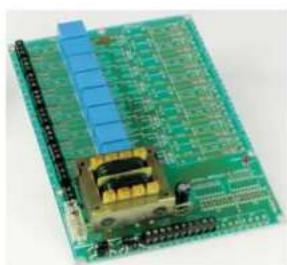
Universal relay card
If you want to switch large electric currents using an electronic control and require control isolation at the same time, then this card is a valuable asset.
Total solder points: 351
Difficulty level: beginner 1 □ 2 □ 3 □ 4 □ 5 □ advanced
natural_image
Green printed circuit board with blue and gold components, no visible text or symbols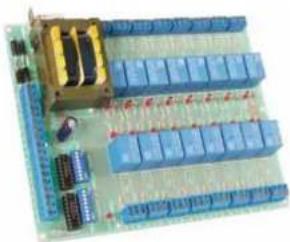
natural_image
Electronic circuit board with blue components and gold connectors (no visible text or symbols)K6714
K6714-16
Features :
☐ The relays can be controlled in different ways: direct control from open-collector outputs, TTL or CMOS level or trough other kits (K6711, K8000, K8023,...)
☑ Every output of the print can be equipped with a noise suppressor network.
☐ Output 12V CC can be used as a power supply for other kits: K6711, K8023,...
Specifications
• Power supply: 230 or 125VAC max. 12VA.
- Output voltage: 12V/250mA.
- PCB dimensions: 150 x 212mm (5.9" x 8.4")
1. Assembly (Skipping this can lead to troubles!)
Ok, so we have your attention. These hints will help you to make this project successful. Read them carefully.
1.1 Make sure you have the right tools:
- A good quality soldering iron (25-40W) with a small tip.
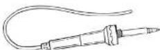
- Wipe it often on a wet sponge or cloth, to keep it clean; then apply solder to the tip, to give it a wet look. This is called 'thinning' and will protect the tip, and enables you to make good connections. When solder rolls off the tip, it needs cleaning.
- Thin raisin-core solder. Do not use any flux or grease.
- A diagonal cutter to trim excess wires. To avoid injury when cutting excess leads, hold the lead so they cannot fly towards the eyes.
- Needle nose pliers, for bending leads, or to hold components in place.
- Small blade and Phillips screwdrivers. A basic range is fine.


For some projects, a basic multi-meter is required, or might be handy

1.2 Assembly Hints :
⇒ Make sure the skill level matches your experience, to avoid disappointments.
⇒ Follow the instructions carefully. Read and understand the entire step before you perform each operation.
→ Perform the assembly in the correct order as stated in this manual
→ Position all parts on the PCB (Printed Circuit Board) as shown on the drawings.
- Values on the circuit diagram are subject to changes

→ Use the check-boxes to mark your progress.
⇒ Please read the included information on safety and customer service
* Typographical inaccuracies excluded. Always look for possible last minute manual updates, indicated as 'NOTE' on a separate leaflet.
1.3 Soldering Hints :
1- Mount the component against the PCB surface and carefully solder the leads

2- Make sure the solder joints are cone-shaped and shiny

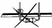
3- Trim excess leads as close as possible to the solder joint

AXIAL COMPONENTS ARE TAPED IN THE CORRECT MOUNTING SEQUENCE
REMOVE THEM FROM THE TAPE ONE AT A

IMPORTANT

To use the relay card with 16 relay outputs, mount the components marked with (*) also (K6714-16).
1. Jump wires.
□ J

ATTENTION : In case you don't use a transistor array (IC's for K6714-16), fit the wire jumpers in the places for IC1 and IC2, marked with a dotted line.
2. Diodes (check the polarity!)

D1 : 1N4148
D2:1N4148
D3:1N4148
D4 :1N4148
5. IC sockets. Watch the position of the notch!
□ IC1:18P. (*)
□ IC2:18P. (*)


Attention : just for K6714-16 !
6. Dip Switch. Watch the orientation!

7. 1/4W Resistors.
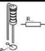
| ☐ | R1 : 1K5 (1 - 5 - 2 - B) (*) |
| ☐ | R2 : 1K5 (1 - 5 - 2 - B) (*) |
| ☐ | R3 : 1K5 (1 - 5 - 2 - B) (*) |
| ☐ | R4 : 1K5 (1 - 5 - 2 - B) (*) |
| ☐ | R5 : 1K5 (1 - 5 - 2 - B) (*) |
| ☐ | R6 : 1K5 (1 - 5 - 2 - B) (*) |
| ☐ | R7 : 1K5 (1 - 5 - 2 - B) (*) |
| ☐ | R8 : 1K5 (1 - 5 - 2 - B) (*) |
| ☐ | R9 : 1K5 (1 - 5 - 2 - B) (*) |
| ☐ | R10 : 1K5 (1 - 5 - 2 - B) (*) |
| ☐ | R11 : 1K5 (1 - 5 - 2 - B) (*) |
| ☐ | R12 : 1K5 (1 - 5 - 2 - B) (*) |
| ☐ | R13 : 1K5 (1 - 5 - 2 - B) (*) |
| ☐ | R14 : 1K5 (1 - 5 - 2 - B) (*) |
| ☐ | R15 : 1K5 (1 - 5 - 2 - B) (*) |
| ☐ | R16 : 1K5 (1 - 5 - 2 - B) (*) |

Attention: just for K6714-16!
8. LEDs. Watch the polarity!
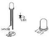
| ☐ | LD1:3mm (*)☐ | LD10:3mm (*) |
| ☐ | LD2:3mm (*)☐ | LD11:3mm (↑) |
| ☐ | LD3:3mm (*)☐ | LD12:3mm (↑) |
| ☐ | LD4:3mm (*)☐ | LD13:3mm (↑) |
9. Terminal blocks

Tree-pole screw connector :
Six-pole screw connector :
□ J18 (3x2p)
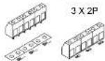
Four-pole screw connector :
220V connections come in the right place.
14. IC's check the position!
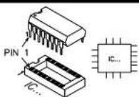
Attention: just for K6714-16!
15. Noise suppression of the relay contacts "OPTIONAL !":
At the standard module K6714 as well K6714-16 have you the opportunity to noise-suppress every relay contact.
First : mount the resistors to noise-suppress the normally open contact of the relay :

Or mount the resistors to noise-suppress the normally closed contact of the relay :

Next mount the capacitors :

16. IMPORTANT :
If you want an electronic controller to be able to switch higher currents and at the same time you need an insulation between the controller and the controlled items, then a relay module is an indispensable help.
The module is very well suited to be connected to our kits K6711 (15 channel IR receiver) and one or two times K8023.
For those two kits power can be taken direct from the relay module. The module can also be used together with the open collector interface module K8000.
The module can of course also be used very well in other applications.
OPTIONS :
In its standard version the module contains 8 relays (K6714), but in the full version the module (K6714-16) contains :
16 relays.
√ DIP switches for manual operation.
√ An indication LED per relay.
√ Two ULN2803 type transistor array (IC's).
You can fit the standard module K6714 with another 8 relays (12V types) yourself. However this requires the installation of additional screw connectors.

The ULN2803 type transistor array allows you to control the relays direct from a TTL or CMOS. For controlling the relay with open collector control, don't mount the transistors arrays.
17. TEST AND CONNECTIONS :
Connect the phase to "0" and the Neutral to "125" or "220", depending on the mains voltage.
Normally the POWER ON LED should be lit now.
In case no manual operation has been provided, you can test the relay by
connecting the inputs (terminals 1 trough 16) to earth (GND) one after another.
Connections possibility's :
- Connect the board to the 15 channel receiver K6711 (see Fig. 1.0)

- Connect the board to the 10 channel, 2 wire remote control K8023 (see Fig. 2.0):

FIG 2.0
18. Remedies in the case of malfunction caused by the relays
If the relays are used to switch alternating voltage, it may be necessary to suppress them.
- Suppressing resistive loads (Lamp, resistor,...):
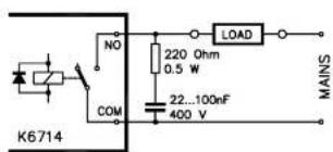
Fig. 3.1
- Suppressing inductive loads (Transformer, motor,...):

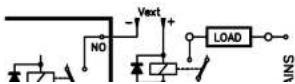
- When above solutions fail :
In this last case an independently feeded DC-relay is used, which is installed as close to the load as possible.

Pay attention to the diode witch is fit ANTI-parallel with the coil, its cathode connected to the plus side, its anode connected to the minus side! This relay MUST be feeded by a separate power supply. The VDR must be suited for the voltage to be switched.
220V - 240V
Siemens SIOV
S14K275
19. INFORMATION FOR UPGRADING YOUR MODULE!
Components necessary to upgrade the K6714 to K6714-16 "16 Relay outputs":
| Component | Quantity | Description | Order Nr. |
| Diodes | 8 | 1N41418 small signal diode. | 1N4148 |
| Resitors 16 1/4W—1K5 | |||
| LED's | 16 | 3mm Rd 1.0 MCD TD universal | LED3RL |
| IC Socket | 2 | 18P DIL IC Socket 300 Mil. | 18P |
| DIP switch | 2 | DS-8 DIP switch 1P and 8Pos. | DS-8 |
| Terminal blocks | 6 | Screw connector print 2 pole Blue | Screw02 |
| Terminal blocks | 8 | Screw connector print 3 pole Blue | Screw03 |
| Relays | 8 | Miniature Rel 12V/15A/1C JZC-22F 1Z | Vr15M121 C |
| IC's | 2 | Octal high Current/High Voltage Driver | ULN2803 |
OPTION : Noise suppression of the relay contacts :
| Component | Quantity | Description | Order Nr. |
| Resistors | 8* | 0,5W / 220 Ohm | RB220E0 |
| Capacitors | 8^ | 100nF / 400V | 15MQ100 or 1/250A |

The quantity shown only pertains to the K6714 with an 8-relay output. Double the quantity if you wish to extend your standard module to a 10-relay output
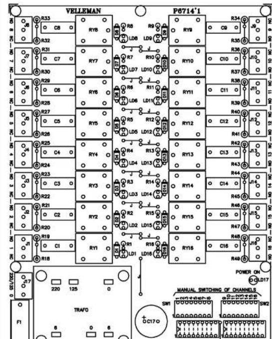
20. PCB
21. Digital selection


natural_image
Symmetrical line drawing of a stylized human head with floral and geometric elements, no text or symbols present.VELLEMAN KIT NV
Legen Heirweg 33
9890 Gavere
Belgium Europe
Info ?: http://www.velleman.be
10 10 10 10 10 10 10
- Universal relay card
- Features :
- Specifications
- Assembly (Skipping this can lead to troubles!)
- Make sure you have the right tools:
- Assembly Hints :
- Soldering Hints :
- AXIAL COMPONENTS ARE TAPED IN THE CORRECT MOUNTING SEQUENCE
- IMPORTANT
- Jump wires.
- Diodes (check the polarity!)
- IC sockets. Watch the position of the notch!
- Dip Switch. Watch the orientation!
- 1/4W Resistors.
- LEDs. Watch the polarity!
- Terminal blocks
- Tree-pole screw connector :
- Six-pole screw connector :
- Four-pole screw connector :
- IC's check the position!
- Noise suppression of the relay contacts "OPTIONAL !":
- IMPORTANT :
- OPTIONS :
- TEST AND CONNECTIONS :
- Connections possibility's :
- Remedies in the case of malfunction caused by the relays
- INFORMATION FOR UPGRADING YOUR MODULE!
- PCB
- Digital selection
Brand : VELLEMAN
Model : K6714-16
Category : Electronics