Aquarian Thermo - Showerhead Aqualisa - Free user manual and instructions
Find the device manual for free Aquarian Thermo Aqualisa in PDF.


| Product Type | Showerhead |
| Brand | Aqualisa |
| Model | Aquarian Thermo |
| Material | Chrome-plated brass |
| Spray Settings | 5 settings: rainfall, massage, mist, jet, eco |
| Flow Rate | 8 L/min (at 3 bar) |
| Connection Size | 1/2 inch BSP |
| Diameter | 100 mm |
| Height | 80 mm |
| Weight | 0.35 kg |
| Installation Type | Wall-mounted |
| Swivel Angle | 30 degrees |
| Cleaning | Wipe with soft cloth; avoid abrasive cleaners |
| Maintenance | Soak in vinegar to remove limescale |
| Safety | Thermostatic temperature control (anti-scald) |
| Warranty | 2 years |
| Spare Parts | Rubber nozzles, O-rings, cartridge |
| Reparability | Cartridge and seals replaceable |
Frequently Asked Questions - Aquarian Thermo Aqualisa
Ensure 1/2 inch BSP connection.
User questions about Aquarian Thermo Aqualisa
0 question about this device. Answer the ones you know or ask your own.
Ask a new question about this device
Download the instructions for your Showerhead in PDF format for free! Find your manual Aquarian Thermo - Aqualisa and take your electronic device back in hand. On this page are published all the documents necessary for the use of your device. Aquarian Thermo by Aqualisa.
USER MANUAL Aquarian Thermo Aqualisa
natural_image
Close-up of a modern electric shower device with metallic body and screw base (no visible text or symbols)Shower systems
natural_image
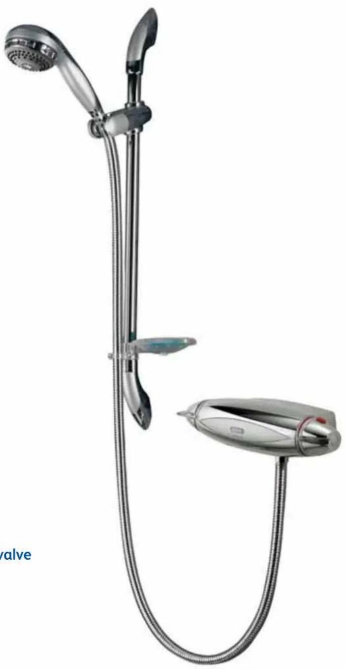
Modern showerhead with adjustable handle and base, no visible text or symbolsAquarian Thermo Surface mounted valve
Chrome E99.01T
White E99.20T
White/chrome E99.21T
Aquarian Thermo (E99.01T) with Varispray adjustable height head (99.40.01)
Components

natural_image
Technical illustration of a streamlined object with internal components and exploded view, including a plastic housing, screw base, and mounting bracket (no text or symbols)Literature not shown
Important information
Introduction
The Aquarian Thermo is a surface mounted thermostatic mixing valve designed to accept rear entry supplies and has outlet connections at the bottom or rear. The Aquarian Thermo provides close temperature stability and fail safe protection when installed on approved gravity or pumped systems and balanced high pressure systems. A cold inlet flow regulator is provided for use with instantaneous (multipoint) gas water heater and combination boiler applications.
If you have any questions at any stage during installation please contact the Aqualisa customer helpline on 01959 560010.
Exposed pipe work installation
The Aquarian Thermo valve can be adapted for installation using exposed pipe work by purchasing a separate manifold system to enable this type of installation.
Please refer to the installation instructions supplied complete with the manifold for fitting instructions.
The manifold is available in either white (for white or white/chrome Aquarian Thermo valves) or grey (for use with chrome Aquarian Thermo valves).
Product codes:
E99MF.20 (white) and E99MF.01 (grey)
should be ordered as required.
Safety information
This product must be installed by a competent person in accordance with all relevant current Water Supply Regulations.
Flushing
Some modern fluxes can be extremely corrosive and, if left in contact, will attack the working parts of this unit. All soldering must be completed and the pipe work thoroughly flushed out in accordance with current Water Supply Regulations prior to connection of the product.
Connections
The Aquarian Thermo valve incorporates ‘push fit’ type connections for use with 15mm British Standard copper tube. Tube should be cut using a rotary type cutter and lubricated using a silicone based lubricant or petroleum jelly (Vaseline or similar) prior to insertion into the fitting. Supply lines must be flushed clear of any debris before installation of the unit. Where plastic pipe is to be used, the tube insert must not increase the tube diameter or extend the cut off length by more than 2mm. The Aquarian Thermo is designed for conventional supplies with HOT on the Left and COLD on the Right as viewed from the front. However, the Aquarian Thermo can be adapted for use with reversed supplies, but it will be necessary to contact Aqualisa customer services on 01959 560010 to purchase reversed graphics to enable this operation. Please refer to the reversed supplies fitting instructions overleaf.
THESE FITTINGS ARE NOT SUITABLE FOR STAINLESS STEEL.
Isolating valves
Suitable isolation valves such as gate valves must be fitted to both supplies in accordance with the current Water Supply Regulations and our terms of warranty.
Due to their restrictive characteristics, stopcocks and ball type valves that reduce the pipe bore size must not be used on gravity or pumped installations.
Filters
To ensure ongoing optimum performance the internal control mechanism 'cartridge' is protected by a two-part filter system. Debris accumulation may result in reduced flow from the shower head and noisy operation.
As this condition is not covered by our standard warranty terms, it is suggested that the cartridge be removed and the filters checked by a competent person. In the event of any difficulties please contact the Aqualisa customer helpline for assistance.

natural_image
Exploded view of a mechanical assembly showing internal components and housing (no text or symbols visible)Important information
Siting
For optimum performance, with gravity fed systems, the distance between the bottom of the storage cistern and the shower head should not be less than 1m (when using an adjustable height shower head). If using a fixed head, the highest point of the pipe work must be not less than 1m below the underside of the cistern. Please refer to the system layouts on the reverse of this guide.
Pump installation
UNDER NO CIRCUMSTANCES MUST A PUMP BE FITTED DIRECTLY TO THE WATER MAIN.
A pump must only be used to boost the pressure from tank-fed supplies. A typical layout is shown on the reverse of this guide.
Stored water capacities
The minimum capacity of the cold storage cistern should not be less than 225 litres (50 gallons). The capacity of the hot cylinder must be capable of meeting the anticipated demand.
Pressures
The Aquarian Thermo shower valve is designed to control static pressure up to 10 bar. Where pressures are likely to exceed 10 bar, a pressure reducing valve (PRV) must be fitted into the incoming mains supply. A setting of 3 bar is recommended. It should be noted that daytime pressures approaching 8 bar can rise above the stated maximum overnight.
The Aquarian Thermo is not suitable for mixed supply systems e.g. gravity hot and cold mains.
A suitable PRV is available from Aqualisa.
Gravity fed hot and cold supplies
The cold supply for the valve assembly must be taken directly from the cold storage system. The hot supply may be taken from the vent/draw off pipe of the hot water cylinder at a point below the cylinder connection or alternatively from the underside of the horizontal draw off.
Rising pipe work must not be connected into the horizontal draw-off from the cylinder or to any point in the vent/draw off pipe above the cylinder connection.
CYLINDER TEMPERATURE IN EXCESS OF 65°C MAY RESULT IN POOR SHOWER PERFORMANCE.
To minimise pressure loss we recommend that the hot and cold supplies are run in 22mm as close as reasonably possible to the mixing valve before reducing to 15mm.
A typical layout is shown on page 17.
Balanced high-pressure system
The Aqualisa Thermo cartridge is designed to operate with unvented hot water storage systems up to a maximum pressure of 10 bar. A PRV must be used if either supply exceeds 10 bar. The cold water supply must be drawn from the same mains supply as that to the hot water system (down stream of the cylinder manufacturers pressure limiting valve, where supplied) and the hot supply from the nearest convenient draw off point. Account must be taken of pressure drops that may occur when other draw-off points are used while the shower is in use.
Pipe work can generally be run in 15mm.
A typical layout is shown on page 17.
Combination boiler/multipoint system
The gas water heater must be capable of raising the temperature of the incoming water by 35irc C and delivering a flow rate of no less than 9 litres (2 gallons) per minute to the shower valve. This is sufficient to operate one outlet point at a time. The Aqualisa Thermo cartridge is designed to operate from the mains at a maximum of 10 bar. If the mains pressure exceeds 10 bar a 'drop tight' PRV must be fitted on the supply pipe after the main stopcock.
The cold supply can be taken from the nearest convenient mains supply and the hot supply can be taken from the nearest hot water draw-off point. Account must be taken of the pressure drops that will occur when other draw-off points are used while the shower is in use.
Pipe work can generally be run in 15mm.
A typical layout is shown on page 17.
Step -by-step instructions
Surface mounted flexible system
!
In addition to the guide below it is essential that the written instructions overleaf are read and understood and that you have all the necessary components (shown overleaf) before commencing installation. Failure to install the product in accordance with these instructions may adversely affect the warranty terms and conditions. Do not undertake any part of this installation unless you are competent to do so. Prior to starting, ensure that you are familiar with the necessary plumbing regulations required to install the product correctly and safely.
The Aquarian Thermo is supplied with universal fixings.
1
In most cases for hollow wall fixing it will be necessary to first install a suitable sound fixing surface within the cavity area before fixing the valve. Mark out the position of the pipe work entry points using the template provided. The 15mm supplies must emerge from the wall at right angles at 150mm pipe centres.

natural_image
Hand holding a metallic mechanical component with a red-handled tool (no text or symbols visible)The template may also be temporarily secured to the wall to ensure correct orientation of the pipe work during making good if required.
2
After making good, using the template, mark and prepare the four fixing points as outlined above.
IT IS ESSENTIAL THAT THE WALL SURFACE IS FLAT AND EVEN TO AVOID DISTORTION OF THE SHOWER BACK PLATE.
3
Remove the fixing screw from the centre of the valve fascia and carefully lift the upper shroud assembly clear from the back plate.

natural_image
Close-up of a metallic tool tip with a red tool inserted, no visible text or symbols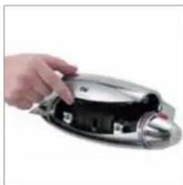
natural_image
Hand placing a component into a metallic housing (no visible text or symbols)4
Remove the two fixing screws to release the lower shroud assembly from the back plate. Carefully remove and set aside.

natural_image
Close-up of a black mechanical component with a red cable inserted, against a white background (no text or symbols visible)
natural_image
Hand holding a disassembled black mechanical device (no visible text or symbols)5
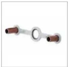
Remove the gripper ring assembly from the rear of the back plate and ensuring correct alignment of the gripper rings, slide over the projecting pipes flush to the wall face.
Cut the supply pipes to their finished length (18mm - 21mm) using a rotary type cutter.
natural_image
Pure mechanical component diagram with two cylindrical ends and a central circular ring (no text or symbols)6
Briefly run the hot and cold supplies to flush out any debris that may be present in the system.
7
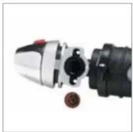
If the valve is being installed for use with a gas fired instantaneous (multipoint) water heater or a combination boiler, the cold water flow regulator must be fitted at this stage by insertion into the cold water port.
(The flow regulator is supplied in its own pack).
natural_image
Close-up of a mechanical component with metallic and black parts, no visible text or symbolsRemove the four cartridge fixing screws and
carefully detach the cartridge assembly from the back plate. Fit the flow regulator into the cold port fully home, with the central O' ring facing the incoming flow. A small length of 15mm pipe may be used to facilitate the installation of this regulator. Refit the cartridge to the back plate using the four fixing screws ensuring the hot and cold markings on the cartridge are uppermost.
8
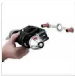
Run a thin bead of silicone sealant in the mastic groove of the back plate. Using a silicone based lubricant, lubricate the projecting pipe ends before carefully pushing the shower valve into position fully home. Secure using the screws provided.
natural_image
Hand holding a black mechanical device with attached circular components (no visible text or symbols)
natural_image
Close-up of a black and silver electrical plug with a red cable (no visible text or symbols)9
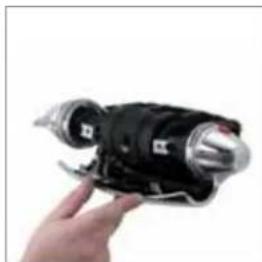
Refit the lower shroud by locating the lugs into the back plate and move the shroud into position. Align the fixing screws with the screw holes, and fix into place ensuring not to overtighten the fixing screws.
natural_image
Hand holding a black and silver robotic device (no visible text or symbols)10
The installation may now be checked for leaks. Turn the on/off knob
(left hand knob) fully forwards to ensure the valve is fully turned off.
Attach the shower hose to the 12 " BSP outlet on the underside of the valve to allow the water to discharge safely to waste.
11
Turn on the supplies and check for any leaks upstream of the valve. Slowly open the on/off control and check for leaks downstream of the valve. If all is sound, turn off the on/off knob fully and turn off the supplies.
natural_image
Hand holding a metallic mechanical component with a stand (no visible text or symbols)12
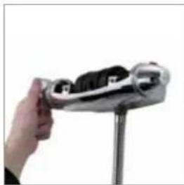
Refit the upper shroud assembly by locating the lugs into the back plate and moving the shroud down into position. Fix using the centrally located locking screw taking care not to overtighten.
13
Remove the paper backing from the badge and push firmly into position in the recess in the shroud assembly.

natural_image
Close-up of a hand holding a small metallic object against a white background (no text or symbols visible)Surface mounted valve with concealed fixed head
!
In addition to the guide below it is essential that the written instructions overleaf are read and understood and that you have all the necessary components (shown overleaf) before commencing installation. Failure to install the product in accordance with these instructions may adversely affect the warranty terms and conditions. Do not undertake any part of this installation unless you are competent to do so. Prior to starting, ensure that you are familiar with the necessary plumbing regulations required to install the product correctly and safely.
The Aquarian Thermo is supplied with universal fixings.
1
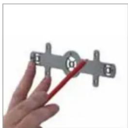
In most cases for hollow wall fixing it will be necessary to first install a suitable sound fixing surface within the cavity area before fixing the valve. Mark out the position of the pipe work entry points using the template provided. The 15mm supplies must emerge from the wall at right angles at 150mm pipe centres.
natural_image
Hand holding a metallic tool with four cross-shaped components and a red cutting edge (no text or symbols visible)The template may also be temporarily secured to the wall to ensure correct orientation of the pipe work during making good if required.
2
After making good, using the template, mark and prepare the four fixing points as outlined above.
IT IS ESSENTIAL THAT THE WALL SURFACE IS FLAT AND EVEN TO AVOID DISTORTION OF THE SHOWER BACK PLATE.
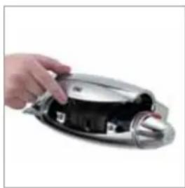
3
Remove the fixing screw from the centre of the valve fascia and carefully lift the upper shroud assembly clear from the back plate.
natural_image
Hand holding a plastic device with internal components (no visible text or symbols)4
Remove the two fixing screws to release the lower shroud assembly from the back plate. Carefully remove and set aside.

natural_image
Hand holding a black and silver mechanical device (no visible text or symbols)5
Remove the gripper ring assembly from the rear of the back plate and ensuring correct alignment of the gripper rings, slide over the projecting pipes flush to the wall face.
Cut the supply pipes to their finished length (18mm - 21mm) and the 22m outlet pipe (17mm - 28mm) using a rotary type cutter.

natural_image
Three copper-colored pipes with flanged ends, no text or symbols visible6
Briefly run the hot and cold supplies to flush out any debris that may be present in the system.
7
Remove the four cartridge fixing screws and carefully detach the cartridge assembly from the back plate.

natural_image
Close-up of a black and silver chain strap with a red string (no text or symbols visible)8
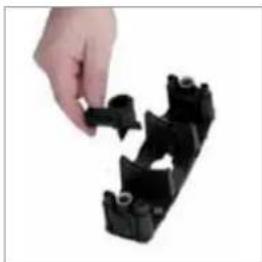
Remove the outlet elbow from the back plate and replace with the 22mm outlet connector.
natural_image
Hand placing a black plastic component into a cluster (no text or symbols visible)
natural_image
Hand holding a black plastic component, no visible text or symbols9
If the valve is being installed for use with a gas fired instantaneous (multipoint) water heater or a combination boiler, the cold water flow regulator must be fitted at this stage by insertion into the cold water port.
(The flow regulator is supplied in its own pack).

natural_image
Close-up of a mechanical component with metallic and black parts, no visible text or symbolsFit the flow regulator into the cold port fully home, with the central O' ring facing the incoming flow. A small length of 15mm pipe may be used to facilitate the installation of this regulator.
10
Refit the cartridge to the back plate.

natural_image
Close-up of a black and red connector with metallic tip (no text or symbols visible)11
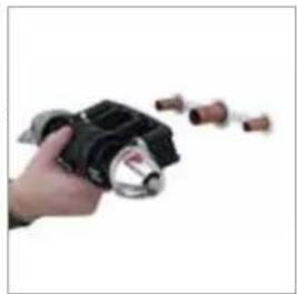
Lubricate the supply pipe ends using a suitable silicone based lubricant and run a thin bead of silicone sealant in the mastic groove of the back plate. Slide the assembly down the projecting pipes flush to the wall surface ensuring the hot and cold markings are uppermost. Secure to the wall using the screws provided.
natural_image
Hand holding a mechanical component with attached connectors (no visible text or symbols)12
The installation may now be checked for leaks. Turn the on/off knob (left hand knob) fully forwards to ensure the valve is fully turned off. If possible, ensure the shower can discharge safely to waste.
13
Turn on the supplies and check for any leaks upstream of the valve. Slowly open the on/off control and check for leaks downstream of the valve. If all is sound, turn off the on/off knob fully and turn off the supplies.

natural_image
Hand holding a black and silver handheld device (no visible text or symbols)14
Refit the lower shroud by locating the lugs into the back plate and moving the shroud into position. Align the fixing screws with the screw holes, and fix into place ensuring not to overtighten the fixing screws.
15
Locate the bottom outlet blanking cap (supplied in the screwpack) into the lower shroud and click into position.

natural_image
Hand holding a small metallic object with black internal components, against a white background (no text or symbols visible)16
Refit the upper shroud assembly by locating the lugs into the back plate and moving the shroud down into position. Fix using the centrally located locking screw taking care not to overtighten.

natural_image
Hand placing a black object into a metallic device (no visible text or symbols)17
Remove the paper backing from the badge and push firmly into position in the recess in the shroud assembly.

natural_image
Close-up of a hand holding a metallic tool or device (no visible text or symbols)Reversed supplies
The Aquarian Thermo is designed for conventional supplies with HOT on the Left and COLD on the Right as viewed from the front. However, the Aquarian Thermo can be adapted for use with reversed supplies, but it will be necessary to contact Aqualisa customer services on 01959 560010 to purchase reversed graphics to enable this operation.
1
Remove the shrouds and cartridge assembly from the backplate as detailed overleaf.
2
Make a note of the orientation of the settings and the position of the on/off knob before removing the fixing screw and pulling the knob clear.

natural_image
Close-up of a black and red electric drill bit with a red tip, against a white background (no text or symbols visible)3
Rotate the cartridge assembly 180irc so the hot and cold temperature markings on the top of the cartridge assembly are now positioned on the bottom of the cartridge.

natural_image
Close-up of a hand holding a black mechanical component with a metallic cylindrical part (no visible text or symbols)4
Replace the existing conventional on/off control graphic ring with the new one purchased separately.

natural_image
Close-up of hands holding a small mechanical component, possibly a tool or device, with no visible text or symbols.5
Replace the control knob ensuring it is in the same position as prior to being removed.
6
If being fitted with a adjustable height head, remove and rotate the outlet connection 180irc to ensure it is positioned at the bottom of the valve.
7
Refit the adapted cartridge assembly to the backplate and refit the shrouds as previously instructed.
!
The shower controls will now be reversed so the on/off control is now on the right and the temperature control on the left as viewed from the front.

natural_image
Metallic object with a pointed tip and rounded body, resembling a stylized pen or tool (no text or symbols visible)After installation...
Commissioning
The Aquarian Thermo is pre-set to a safe maximum shower temperature. During use, the action of the stop button may be overridden by depressing it as the temperature control is rotated. Should it be necessary to reset the maximum temperature position, please observe the following procedures.
- Ensure that the hot water system is at normal maximum temperature.
- Turn the temperature control lever to the full cold position (lever fully downwards).
- Remove the temperature control fixing screw and pull the knob clear.
- Remove the temperature control lever screws and pull the lever clear.
- With the cam tooth engaged in the shaft sleeve keyway, turn the sleeve in the appropriate direction to increase or decrease the maximum temperature. (Each increment equates to approximately 1irc C).
6 Relocate the cam into the cam locking ring and turn the shaft sleeve through 180° (one half turn) to lock the cam down. - Depress the red stop button and replace the temperature control knob in the full cold position and secure using the fixing screw.
- Test the shower by turning it on and slowly increasing the temperature. At the selected point, the button should pop up and prevent further movement. Repeat the above process if the maximum temperature stop button needs further adjustment.
- When the stop button is at the desired limit, refit the screw cover in the control knob.
Should the shrouds need to be removed at any time, turn the knob fully clockwise to the off position. Carefully depress the left hand side of the badge in the middle of the front shroud fascia using a suitable tool taking care not to damage the badge or the surrounding plated surfaces. The right hand side of the badge will lift clear of the recess enabling you to remove the badge, giving you access to the small screw fixing the shroud in place. Remove the screw and lift the top shroud assembly clear.
Remove the two fixing screws from the valve assembly and pull the bottom shroud clear.
Should the knobs need to be removed at any time, turn the knob fully downwards to the off position. Remove the screw covers from the middle of the control knobs with a suitable tool taking care not to damage the surrounding plated areas. Remove the fixing screws and pull the knob clear.
Should unacceptable damage to the badge occur when removing it from the recess, please contact Aqualisa customer services who will send a free of charge replacement.
User Guide

natural_image
Close-up of a hand holding a metallic object with a handle, mounted on a stand (no visible text or symbols)Shower operation
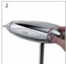
1 Turn the on/off knob fully into the open position to turn the shower on. N.B. The on/off MUST NOT be used as a method of flow control.
natural_image
Close-up of a hand holding a metallic pen tip with a pointed tip, mounted on a stand (no text or symbols visible)2 Rotate the temperature control lever to select a comfortable showering temperature using the temperature markings as a guide. Turn the on/off knob fully into the closed position after use.
After installation
Run through the Aquarian Thermo operation with the purchaser and hand them this guide. Complete and post the Aquarian Thermo guarantee card or register online at www.aqualisa.co.uk.
Cleaning
Your Aquarian Thermo shower valve should be cleaned using only a soft cloth and washing up liquid. DO NOT USE ABRASIVE CLEANERS.
Cleaning the filters
As this condition is not covered by our standard warranty terms, it is suggested that the cartridge be removed and the filters checked by a competent person. In the event of any difficulties please contact the Aqualisa customer helpline for assistance.
- Turn off the supplies to the shower and carefully remove the shrouds as detailed overleaf.
- Remove the cartridge as detailed overleaf.
- Carefully ease the inlet filters from their housings by rotating them a quarter turn anti-clockwise.
- Backwash the filters under a running tap or using a mild solution of vegetable based descalent if required.
- Refit the filters into the inlet ports and carefully replace the cartridge ensuring the hot and cold markings are uppermost.
- Refit the shrouds as detailed overleaf.
Trouble shooting guide
Symptom Possible cause Action
| Water output is either all hot or all cold, or cold only | Reversed inlet supplies Check that the supplies correspond with the inlet markings | |
| Water output is not hot enough | The temperature of the hot water cylinder is too low | The cylinder temperature should be at least 15°C hotter than the blend |
| Water flow through the appliance is too fast | Check the flow rate recommendations with the heater manufacturer | |
| Flow rate is poor and water temperature is low | Airlock in the water supply Check that the pipe work is laid in accordance with the correct practices, paying particular attention to potential air-traps | |
| Water temperature regularly swings between hot and cold | Cold water pressure is too high | If the static water pressure exceeds 7 bar (100 psi) install a pressure reducing valve (PRV) in accordance with the installation guide |
| The flow regulator has not been fitted | Fit the flow regulator | |
| Poor flow rate Twisted hose | Debris in shower head | Check and clear as necessary |
| Debris in filters | ||
| Debris in cold inlet flow regulator | ||
Typical installations
Typical gravity system installation

flowchart
graph TD
    A["Supply"] --> B["Vent and draw-off pipe to hot water"]
    B --> C["Hot water cylinder"]
    C --> D["Connect: 'A' or 'B'"]
    D --> E["Underside of cistern"]
    E --> F["Highest point must be 1m below underside of cistern"]
    style A fill:#f9f,stroke:#333
    style B fill:#bbf,stroke:#333
    style C fill:#ff9,stroke:#333
    style D fill:#ff9,stroke:#333
    style E fill:#f9f,stroke:#333
    style F fill:#f9f,stroke:#333
Typical Thermal storage unit system installation

Typical pumped system installation Typical UHW system installation
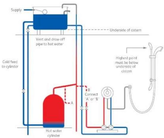
flowchart
graph TD
    A["Supply"] --> B["Vent and draw-off pipe to hot water"]
    B --> C["Cold feed to cylinder"]
    C --> D["Hot water cylinder"]
    D --> E["A"]
    E --> F["B Connect 'A' or 'B'"]
    F --> G["Highest point must be below underside of cistern"]
    G --> H["Underside of cistern"]
    H --> I["Top outlet"]
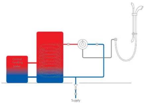
flowchart
graph LR
    A["Central Heating Boiler"] --> B["Reactor Unit"]
    B --> C["Supply"]
    C --> D["Main Pipe"]
    D --> E["Valve"]
    E --> F["Outlet"]
    style A fill:#f9f,stroke:#333
    style B fill:#ff9,stroke:#333
    style C fill:#ffcc,stroke:#333
    style D fill:#fff,stroke:#333
    style E fill:#fff,stroke:#333
    style F fill:#fff,stroke:#333
Typical combination boiler installation


natural_image
Abstract logo design with white, blue, and red segments on gray background (no text or symbols)- Shower systems
- Components
- Important information
- Introduction
- Exposed pipe work installation
- Safety information
- Flushing
- Connections
- Isolating valves
- Filters
- Siting
- Pump installation
- Stored water capacities
- Pressures
- Gravity fed hot and cold supplies
- Balanced high-pressure system
- Combination boiler/multipoint system
- Step -by-step instructions
- Surface mounted flexible system
- !
- 1
- 2
- 3
- Surface mounted valve with concealed fixed head
- 4
- Reversed supplies
- After installation...
- Commissioning
- User Guide
- Shower operation
- After installation
- Cleaning
- Cleaning the filters
- Trouble shooting guide
- Typical installations
Brand : Aqualisa
Model : Aquarian Thermo
Category : Showerhead