
NHD-100-RX - Digital decoder WyreStorm - Free user manual and instructions
Find the device manual for free NHD-100-RX WyreStorm in PDF.


| Product Type | Digital Decoder (HD over IP Receiver) |
| Model | NHD-100-RX |
| Brand | WyreStorm |
| Video Input | 1 x LAN (H.264/MPEG-4 AVC stream, 480p@60Hz ~ 1920x1200@60Hz) |
| Video Output | 1 x HDMI 1.3 (up to 1920x1200@60Hz) |
| Audio Input | Embedded in streaming media input via LAN |
| Audio Output | 1 x Phoenix Connector (Stereo) |
| Control Method | PC Configurator, RS-232 |
| End-to-End Latency | 60 ms ~ 90 ms (Low latency mode), 250 ms ~ 300 ms (High quality mode) |
| Power Supply | 12V 1A DC (also supports PoE Class 0) |
| Power Consumption | 6W (Max.) |
| Operating Temperature | +32°F ~ +113°F (0°C ~ +45°C), 10% ~ 90% non-condensing |
| Storage Temperature | -4°F ~ 140°F (-20°C ~ +70°C), 10% ~ 90% non-condensing |
| ESD Protection | Human body model: ±8kV (air-gap discharge), ±4kV (contact discharge) |
| Surge Protection | ±1 kV |
| Product Dimensions (WxHxD) | 228mm x 25mm x 111mm (9.0" x 1.0" x 4.4") |
| Case Dimensions (WxHxD) | 310mm x 76mm x 180mm (12.2" x 3.0" x 7.1") |
| Weight | 0.6 kg |
| Certification | CE, FCC, RoHS compliant |
| Included Accessories | Power adapter (12V 1A DC), 3 detachable international plugs, 3 x Phoenix connector (male, 3.5mm, 3 pin), 2 mounting ears |
| Maintenance | Clean with a soft, dry cloth only. Do not use alcohol, paint thinner or harsh chemicals. |
| Warranty | 3 years parts and labor |
Frequently Asked Questions - NHD-100-RX WyreStorm
User questions about NHD-100-RX WyreStorm
0 question about this device. Answer the ones you know or ask your own.
Ask a new question about this device
Download the instructions for your Digital decoder in PDF format for free! Find your manual NHD-100-RX - WyreStorm and take your electronic device back in hand. On this page are published all the documents necessary for the use of your device. NHD-100-RX by WyreStorm.
USER MANUAL NHD-100-RX WyreStorm
WyreStorm HD over IP Solutions
HD over IP AV distribution solution utilising H.264 compression for AV switching over a LAN
HDMI™
HIGH DEFINITION MULTIMEDIA INTERFACE

HDCP COMPLIANT
Part Number NHD-000-CTL NHD-100-TX NHD-100-RX
Instruction Manual

RoHS

CE
FC
Thank you for choosing this WyreStorm product. Please read these instructions carefully before installing to avoid complications later.
Contents
1 Introduction
2 Features
3 Safety Precautions
4 In the Box
5 Before Installation
6 Specifications
7 Panel Description
8 Connection
9 Typical Application
i. One Encoder to One Decoder
ii. One Encoder to Multiple Decoders
iii. Multiple Encoders to Multiple Decoders
10 Switch Settings and Requirements
11 NHD-000-CTL Browser Configuration & Control
i. Matrix Switching Commands
ii. TX/RX Settings
iii. CTL Settings
12 NetworkHD™ Console Configuration
i. NetworkHD™ Console Software Installation
ii. Searching Devices
iii. Setting Device Parameters
iv. Device Settings
v. Creating Scenes
vi. Configuration File Management
vii. Serial Control
viii. CEC Control
ix. Viewing the Encoders Preview Stream
x. Log
13 Additional Information
14 NetworkHD™ Protocol
15 Troubleshooting
16 FAQ
17 Maintenance
18 Provided Service
19 Mail In Service
20 Warranty
21 Warranty Limits and Exclusions
22 Disclaimer
23 Installation Reference Logs
1. Introduction
WyreStorm® NetworkHD™ 100 is our premier H.264 HD over IP distribution platform. With its simple system configuration and robust feature set, it provides the best value in networked video distribution, without compromising quality. Enabling the distribution of HDMI over a dedicated IP network switch for commercial AV applications.
NetworkHD ^™ 100 facilitates the transmission of an HDMI 1.3 signal (including Full HD 1080p video with 2.1 audio) to any number of HDMI displays over standard Ethernet (Cat5e/6) infrastructure.
The modular system architecture of NetworkHD ^™ 100 removes the limitations of a traditional fixed platform I/O matrix system without compromising quality or reliability, whilst offering significant cost savings when designing large scale installations. Adding encoders and decoders as required enables the system to grow with the needs of the application.
NetworkHD™ 100 uses multiple technologies to automatically configure and discover system components, making setup a breeze. Functioning on 10/100 or Gigabit Layer2 SMART switches, NetworkHD™ 100 does not require advanced integrator network experience to install, nor does it require complicated VLAN configurations or PC software, making it one of the simplest HD over IP systems available. Configuring network switches takes minutes through your browser and even the largest distributions can be quickly and easily configured and expanded.
The NHD-000-CTL controller creates a simple, single interface to configure, manage and control the entire NetworkHD™ 100 system, whilst capable of integrating with leading control brands including WyreStorm Enado™ for the highest quality total HD distribution and control solution over a network.
For further information on this product and other WyreStorm ranges, visit our website or download our latest product guide at wyrestorm.com
2. Features
- Highly scalable, visually lossless HD over IP solution using the most efficient compression technology to allow for very large commercial AV deployments
- Plug and Play setup with automatic networking configuration and auto discovery of components
- Quick Sync™ technology for virtually instantaneous, seamless switching
• CEC One-Touch Play & Standby or RS-232 control of connected displays - Supports video previewing on a PC or third party device. NetworkHD ^TM 100 outputs simultaneous IP streams. One full resolution for the NHD-100-RX. The other small one supports resolutions of 352 x 288 @ 5Hz to easily preview a video from the encoder on a PC or Mac
- Use with the new NHD-000-CTL controller for simple configuration and control via the LAN, as well as for allowing control from third party control system such as AMX, Crestron, Control4, RTI & WyreStorm™ Enado.
• Supports PoE to enable remote powering from POE network switches, eliminating the need for a nearby power outlet
• Full PC control suite available free of charge at wyrestorm.com - Supports HDCP
- Configurable encoding bit rate up to 40 Mbps
3. Safety Precautions

WARNING
To reduce the risk of fire, electric shock or product damage:
- Ventilation is crucial to consistent operation of this product. Units should be mounted with at least (2.5cm) 1 inch clearance of vents. WyreStorm highly recommends the use of the NHD-000-RACK for absolute correct mounting best practice.
- Do not expose this apparatus to rain, moisture, sprays, drips or splashes and ensure that no objects containing liquids are placed on the apparatus, including cups, glasses and vases.
-
Do not place this unit in a confined space such as enclosed shelving, cabinets or bookshelves. Ensure the unit is adequately ventilated.
-
To prevent the risk of electric shock or fire hazard due to overheating, do not cover the unit or obstruct ventilation openings with material, newspaper, cardboard or anything that may restrict airflow into the unit.
- Do not install near external heat sources such as radiators, heat registers, boilers or any device that produces heat such as amplifiers or computers and do not place near sources of naked flame.
- Unplug apparatus from power supply during lightening storms or when unused for long periods of time.
- Protect the power cable from being walked on, pinched or restricted in any way, especially at plug connections.
- Only use attachments/accessories specified by the manufacturer.
- Units contain non-servicable parts - Refer all servicing to qualified service personnel
4. In the Box
NHD-100-TX
1 x NHD-100-TX Main Unit
1 x Power Adapter (12V 1A DC)
3 x Detachable International Plug s
2 x Phoenix Connector (Male, 3.5 mm, 3 pin)
2 x Mounting Ears
NHD-100-RX
1 x NHD-100-RX Main Unit
1 x Power Adapter (12V 1A DC)
3 x Detachable International Plug s
3 x Phoenix Connector (Male, 3.5 mm, 3 pin)
2 x Mounting Ears
NHD-000-CTL
1 x NHD-000-CTL Main Unit
1 x Power Adapter (12V 1A DC)
3 x Detachable International Plug s
1 x Phoenix Connector (Male, 3.5 mm, 4 pin)
2 x Mounting Ears
5. Before Installation
Introduction
This guide is intended for installation project managers to ensure you are aware of WyreStorm's installation best practice guidelines that we know will improve the installation experience. These issues have been gathered from thousands of installation reports, support calls and our own personal experiences to prevent issues that cost hours in troubleshooting and protracted site visits to fix.
Preparation
Build and test the rack and all hardware components off site. Doing so will find any issues before moving to the hectic and time sensitive environment of the install itself. Knowing that a unit was working properly before makes it far easier to pinpoint the cause of the problem saving time and money.
Network Equipment & Switches
NetworkHD™ can be operated with recommended Layer 2 Gigabit Smart Switches provided the overall switching capacity or backplane capacity of the switch meets the requirements of the number of encoders/decoders you have on your network.
WyreStorm NetworkHD is built to run over a standard network infrastructure, however the quality of this infrastructure is critical. We have tested many brands of switches all of which perform well in small system configurations of around 10 Encoders and Decoders. However, for larger installations, WyreStorm highly recommends using CISCO SG500 or CATALYST series switches.
NetworkHD requires a Layer 2 managed switch with support for Multicast & IGMP snooping enabled. Do not connect any encoders to the switch until this has been configured. For recommended switches and PDF configuration guides please see the 'downloads' section of any NetworkHD device at wyrestorm.com.
It is not necessary to change the IP addresses of the TX and RX units – AutolP is used to configure correct IP addresses. DHCP or Static IP addresses are not recommended unless absolutely required. Failure to note or errors in the IP settings of a unit may result in a complicated reset procedure.
Most NetworkHD installations use POE (Power Over Ethernet) to power the RX & TX units. NetworkHD 100 & 200 components are Class 0 rated POE devices meaning that they can require up to 15.4W of power each, however their real power draw is between 5-7W.
In order to calculate the number of devices that can be used on a switch please divide the total POE power capability of the switch by 15.4 and round down. For Example the CISCO SG300-52P with a POE power output of 375W: 375 / 15.4 = 24.35. Therefore 24 devices can be powered by this switch.
In order to have all ports powered by POE on a switch an MP series should be used in this example an SG300-52MP which provides 740W. 740 / 15.4 = 48. Therefore 48 devices can be powered by this switch.
Each NHD-100-TX encoder will produce up to 50Mb/s of data > therefore 10 x encoders will require 10 x 50Mb/s = 0.5 Gbps.
! If you are unsure about the network requirements for your NetworkHD™ system please contact WyreStorm or your local WyreStorm distribution partner for support.
WyreStorm are not liable if network bandwidth is to blame for poor performance from the NetworkHD™ system.
NetworkHD ^™ does not require multiple VLANs to be configured. Third-party controllers communicate directly with the NHD-000-CTL rather than the Ethernet switch.
Visit wyrestorm.com for guides on detailed switch configuration and recommended switch suggestions for different sized NetworkHD ^™ systems.
Power
Your installation is nothing without power. Use a UPS (Uninterruptible Power Supply) to ensure a clean, consistent power supply to all components in the rack. Be sure to calculate your total load and run time requirements ahead and leave enough room in the rack.
Heat
High temperatures are the biggest killer of electronic products. Just a 3° Celsius rise in external temperature can equate to a 15° degree rise in internal temperature and trigger thermal runaway. Ensure proper rack design and passive or active cooling strategies are used to properly move heat away from the components in the rack. Poor installation of cables looks messy and creates hotspots that prevent heat moving away from components – avoid this at all costs.
The NHD-IP-RACK & NHD-000-RACK have been designed for optimal mounting of the NetworkHD Encoders in the rack and should always be used. Encoders and decoders should never be laid flat or stacked on top of each other. At least 1.5 inches of clearance should be left by the vents to ensure adequate airflow through the units.
Software
Where possible WyreStorm ship all components with the most up to date firmware and software, however before starting any installation please check the downloads section of the products on WyreStorm.com to ensure there are no updates to your system components. Please also try to use the latest firmware on all related hardware – particularly switches and TVs. Please check with the relevant manufacturer for upgrade instructions.
Redundancy
With all the planning in the world, even the most experienced installers make mistakes and accidents will always happen. For this reason, it is best practice to always run two cables to each Decoder location. This may increase the cost of cabling but is nothing compared to replacing a single or even multiple defective cables that have been sealed into the wall.
Although WyreStorm are incredibly proud of the reliability and robustness of our products from time to time units can fail. Therefore, mission critical products such as the CTL and Decoders in hard or impossible to access locations should be installed with spare, redundant units that can be swapped to if required.
Mounting/Installation
All WyreStorm products should be mounted so that the logo and text printed on the unit is correctly aligned. This will allow for the optimal airflow through the product. As already stated the vents should not be obstructed with adequate clearance. Units should be secured using suitable fixings such as those supplied in the box.
Source & Display settings
WyreStorm NetworkHD components use the highest quality encoders available to provide visually lossless compression over a large number of displays. However, the compression can only be as good as the source content that is put in. NetworkHD 100/200 series use H.264 compression that is not compatible with interlaced sources. Please ensure that all source content is set to Progressive scan (720p/1080p) and not interlaced (1080i).
On the displays and sources – low power modes should be disabled to ensure the system is always fed with content. The customer does not want to be troubleshooting if the source has gone into standby.
The displays should have CEC enabled so that NetworkHD can power them on and off. This setting is called different things by different manufacturers and is not always enabled by default. Any screens that are used in video walls must also have Over Scan disabled. This setting is always enabled by default and often hidden in advanced settings menus. Without it disabled the video wall will not align.
Testing & Certification
WyreStorm products are manufactured and testing to the highest standards but the best installation environment is paramount to successful installation. The only way to guarantee the installation is fit for purpose is to test and certify cables. All IT cable companies will certify cables throughout a network as standard, yet they are passing a fraction of the data in short bursts that NetworkHD transmits 24/7. Although testing a cable proves that it is correctly terminated, it does not show how much interference on the run is affecting bandwidth. Certification of every cable should always be performed before and after walls are sealed.
Cable Type & 4K support
WyreStorm are always striving to improve our technologies and although your system is the best available today – what lies ahead is not always clear. All you can do is prepare your installation as best you can for future technologies. Running extra cables to all display locations to provide extra bandwidth for future technologies. Ensuring source components are located next to transmitters with HDMI cables that are as short as possible as HDMI distances will reduce as content bandwidth increases. Use trunking so that cables can be easily replaced down the line. Never seal HDMI cables in the wall as they cannot be re-terminated or replaced easily.
6. Specifications
NHD-100-TX
| TECHNICAL | |
| Input Video Ports 1 × DVI IN | |
| Input Video Type HDMI, DVI | .0, VGA, Component |
| Input Video Resolutions | HDMI:640 x 480 @ 60Hz, 480p @ 60Hz, 576p @ 50Hz, 800 x 600 @ 60Hz, 1024 x 768 @ 60Hz, 720p @ 50Hz, 720p @ 60Hz, 1280 x 800 @ 60Hz, 1280 x 1024 @ 60Hz, 1360 x 768 @ 60Hz, 1366 x 768 @ 60Hz, 1400 x 1050 @ 60Hz, 1440 x 900 @60Hz, 1680 x 1050 @ 60Hz, 1080p @ 24Hz, 1080p @ 25Hz, 1080p @ 30Hz, 1080p @ 50Hz, 1080p @ 60Hz, 1920 x 1200 @ 60Hz |
| Input Video Signal 0.5 ~ 1.2 V | p-p |
| Encoding Data Rate Up to 30 | Mbps, configurable |
| Output Video Ports 1 x LAN | |
| Output Video Type H.264/MPEG-4 AVC | |
| Output Video Resolutions | Large IP stream: 480p @ 60Hz ~ 1920 x 1200 @ 60HzSmall IP stream: 352 x 288 @ 5Hz |
| Video Impedance 100 Ω | |
| Input DDC Signal 5 V p-p (TTL) | |
| End-to-End Time Latency | About 60 ms-90 ms (Low latency mode)About 250 ms-300 ms (High quality mode) |
| AUDIO | |
| Input Audio Ports 1 x Audio Jack | |
| Input Audio Format Stereo | |
| Output Audio Ports 1 x Phoenix | Connector |
| Output Audio Format Stereo | |
| CONTROL | |
| Control Method Rear panel source switch, PC configurator and RS-232 | |
| GENERAL | |
| Operating Temperature +32°F ~ +113°F (0°C ~ +45°C) 10% ~ 90%, non-condensing | |
| Storage Temperature -4°F ~ 140°F (-20°C ~ +70°C) 10% ~ 90%, non-condensing | |
| Power 12V 1A DC | |
| Power Consumption 6W (Max.) | |
| ESD Protection | Human body model:±8kV (air-gap discharge)±4kV (contact discharge) |
| Surge Protection Voltage ±1 kV | |
| Case Dimensions (WxHxD) 310mm x 76mm x 180mm / 12.2" x 3.0" x 7.1" | |
| Product Dimensions (WxHxD) | 200mm x 25 mm x 94mm / 7.9" x 1.0" x 3.7" |
| Weight | 0.48 Kg |
| Certification | CE, FCC, RoHS compliant |
NHD-100-RX
| TECHNICAL | |
| Input Video Ports | 1 × LAN |
| Input Video Type | H.264/MPEG-4 AVC |
| Input Video Resolutions | 480p @ 60Hz ~ 1920 x 1200 @ 60Hz |
| Output Video Ports | 1 x HDMI |
| Output Video Type | HDMI 1.3 |
| Output Video Resolutions | HDMI480p @ 60Hz, 576p @ 50Hz, 800 x 600 @ 60Hz, 1024 x 768 @ 60Hz, 720p @ 50Hz,720p @ 60Hz, 1280 x 800 @ 60Hz, 1280 x 1024 @ 60Hz, 1366 x 768 @60Hz, 1440 x 900 @ 60Hz,1600 x 1200 @ 60Hz, 1680 x 1050 @ 60Hz, 1080p @ 24Hz, 1080p @ 25Hz, 1080p @ 30Hz,1080p @ 50Hz, 1080p @ 60Hz, 1920 x 1200 @ 60Hz |
| Video Impedance 100 Ω | |
| End-to-End Time Latency | About 60 ms-90 ms (Low latency mode)About 250 ms-300 ms (High quality mode) |
| AUDIO | |
| Input Audio Ports 1 x LAN | |
| Input Audio Format Audio embedded in streaming media input | |
| Output Audio Ports 1 x Phoenix | Connector |
| Output Audio Format Stereo | |
| CONTROL | |
| Control Method PC configurator and RS-232 | |
| GENERAL | |
| Operating Temperature +32°F ~ +113°F (0°C ~ +45°C) 10% ~ 90%, non-condensing | |
| Storage Temperature -4°F ~ 140°F (-20°C ~ +70°C) 10% ~ 90%, non-condensing | |
| Power 12V 1A DC | |
| Power Consumption 6W (Max.) | |
| ESD Protection | Human body model:±8kV (air-gap discharge)±4kV (contact discharge) |
| Surge Protection Voltage ±1 kV | |
| Case Dimensions (WxHxD) 310mm x 76mm x 180mm / 12.2" x 3.0" x 7.1" | |
| Product Dimensions (WxHxD) 228mm x 25 mm x 111mm / 9'.0' x 1.0" x 4.4" | |
| Weight | 0.6 Kg |
| Certification | CE, FCC, RoHS compliant |
7. Panel Description
NHD-000-CTL Front
1 Reset Button
2 Status Indicator: ON - NHD-000-CTL works properly. Off - NHD-000-CTL is not in the normal working state.

3 Power indicator: ON - NHD-000-CTL is powered on. Off - NHD-000-CTL is powered off.
NHD-000-CTL Rear
1 AV LAN (POE) - connect to the same switch/VLAN as the NHD Encoders & Decoders
2 CONTROL LAN (POE) - connect to the same switch/VLAN as the control system and configuring PCs.

3 RS232 - connects to a RS-232 device such as a computer for debugging and upgrading the NHD-000-CTL
4 Power Input - Connects to a power adapter, 12V 1A DC.
NHD-100-TX Front
1 Power indicator: ON - NHD-100-TX is powered on. Off - NHD-100-TX is powered off.
2 Status Indicator: ON - NHD-100-TX works properly. Off - NHD-100-TX is not in the normal working state.

NHD-100-TX Rear
1 HDMI IN - connect to local HDMI source devices with HDMI 1.4 cables or DVI to HDMI cables.
2 AUDIO OUT - connects to an audio output device such as an amplifier for audio de-embedding output.
3 LAN (POE) - used for a streaming media output.
4 RS-232 - connects to a RS-232 device such as a computer for debugging and upgrading the NHD-100-TX.
5 Power Input - Connects to a power adapter, 12V 1A DC.

1 Power indicator: ON - NHD-100-RX is powered on. Off - NHD-100-RX is powered off.
2 Status Indicator: ON - NHD-100-RX works properly. FLASHING - NHD-100-RX is not linked to NHD-100-TX

NHD-100-RX Rear
1 Grounding Screw - connects to the ground for preventing from electric shock and device damage.
2 Power Input - connects to a power adapter, 12V 1A DC.
3 LAN (POE) - connects to a switch for streaming media input.
4 HDMI OUT - connects to an A/V device such as a display for A/V output.
5 AUDIO OUT - connects to an audio output device such as an amplifier and a speaker for de-embedded stereo output.
6 RS-232 1 - connects to a RS-232 device such as a computer for debugging NHD-100-RX.
RS-232 2 - connects to a RS-232 device for serial communication with this device via PC configurator.

8. Connection
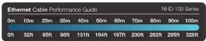
! Ensure good quality cabling is used throughout your system, with no electrical interference, bends, twists, kinks, or other issues that may interfere with signal transmission, including the use of patch panels or wall outlets. Cable connectors should also be in good condition and correctly terminated to required standards, with straight cable runs used where possible and plugs securely connected to ports without straining port enclosures.
The presence of any of these factors in your system can jeopardize successful signal distribution and should be eliminated wherever possible.

Poor terminations leads to intermittent performance and longer install times.
Ethernet Wiring Guide
The quality
of
bar
| Time | Performance | | ---- | ----------- | | 0m | 32ft | | 10m | 65ft | | 20m | 98ft | | 30m | 131ft | | 40m | 164ft | | 50m | 197ft | | 60m | 230ft | | 70m | 262ft | | 80m | 295ft | | 90m | 326ft | | 100m | 326ft |9. Typical Application
i. One Encoder To One Decoder
In order to use NetworkHD™ components in this configuration, the units must first have the signal correctly routed between them. In order to facilitate this, they must first be connected to a network so that the NHD-000-CTL or NetworkHD™ Software Console can be used to route the signal.
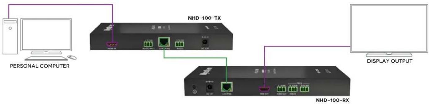
flowchart
graph TD
    A["PERSONAL COMPUTER"] --> B["NHD-100-TX"]
    B --> C["NHD-100-RX"]
    C --> D["DISPLAY OUTPUT"]
    B --> E["OUTPUT"]
    style A fill:#f9f,stroke:#333
    style B fill:#ccf,stroke:#333
    style C fill:#cfc,stroke:#333
    style D fill:#fcc,stroke:#333
ii. One Encoder To Multiple Decoders

flowchart
graph TD
    A["MEDIA SERVER"] --> B["NHD-100-TX"]
    A --> C["NHD-100-RX"]
    A --> D["NHD-100-RX"]
    B --> E["Network Port 1"]
    B --> F["Network Port 2"]
    B --> G["Network Port 3"]
    C --> H["Network Port 4"]
    C --> I["Network Port 5"]
    C --> J["Network Port 6"]
    D --> K["Network Port 7"]
    D --> L["Network Port 8"]
    D --> M["Network Port 9"]
    D --> N["Network Port 10"]
    style A fill:#f9f,stroke:#333
    style B fill:#ccf,stroke:#333
    style C fill:#ccf,stroke:#333
    style D fill:#ccf,stroke:#333
    style E fill:#dfd,stroke:#333
    style F fill:#dfd,stroke:#333
    style G fill:#dfd,stroke:#333
    style H fill:#dfd,stroke:#333
    style I fill:#dfd,stroke:#333
    style J fill:#dfd,stroke:#333
    style K fill:#dfd,stroke:#333
    style L fill:#dfd,stroke:#333
    style M fill:#dfd,stroke:#333

flowchart
graph TD
    A["MEDIA SERVER"] --> B["BLU-RAY"]
    B --> C["NHD-100-TX"]
    C --> D["NHD-100-RTL"]
    D --> E["NHD-100-RX"]
    E --> F["DISPLAY OUTPUT"]
    B --> G["NHD-100-TX"]
    G --> H["NHD-100-RTL"]
    H --> I["NHD-100-RX"]
    I --> J["DISPLAY OUTPUT"]
    style A fill:#f9f,stroke:#333
    style B fill:#ccf,stroke:#333
    style C fill:#cfc,stroke:#333
    style D fill:#fcc,stroke:#333
    style E fill:#cff,stroke:#333
    style F fill:#ffc,stroke:#333
    style G fill:#cfc,stroke:#333
    style H fill:#cfc,stroke:#333
    style I fill:#cfc,stroke:#333
    style J fill:#ffc,stroke:#333
10. Switch Settings & Requirements
Network Equipment & Switches
NetworkHD™ can be operated with recommended Layer 2 Gigabit Smart Switches provided the overall switching capacity or backplane capacity of the switch meets the requirements of the number of encoders/decoders you have on your network.
WyreStorm NetworkHD is built to run over a standard network infrastructure, however the quality of this infrastructure is critical. We have tested many brands of switches all of which perform well in small system configurations of around 10 Encoders and Decoders. However, for larger installations, WyreStorm highly recommends using CISCO SG500 or CATALYST series switches.
NetworkHD requires a Layer 2 managed switch with support for Multicast & IGMP snooping enabled. Do not connect any encoders to the switch until this has been configured. For recommended switches and PDF configuration guides please see the 'downloads' section of any NetworkHD device at wyrestorm.com.
It is not necessary to change the IP addresses of the TX and RX units – AutoIP is used to configure correct IP addresses. DHCP or Static IP addresses are not recommended unless absolutely required. Failure to note or errors in the IP settings of a unit may result in a complicated reset procedure.
Most NetworkHD installations use POE (Power Over Ethernet) to power the RX & TX units. NetworkHD 100 & 200 components are Class 0 rated POE devices meaning that they can require up to 15.4W of power each, however their real power draw is between 5-7W.
In order to calculate the number of devices that can be used on a switch please divide the total POE power capability of the switch by 15.4 and round down. For Example the CISCO SG300-52P with a POE power output of 375W: 375 / 15.4 = 24.35. Therefore 24 devices can be powered by this switch.
In order to have all ports powered by POE on a switch an MP series should be used in this example an SG300-52MP which provides 740W. 740 / 15.4 = 48. Therefore 48 devices can be powered by this switch.
Each NHD-100-TX encoder will produce up to 50Mb/s of data > therefore 10 x encoders will require 10 x 50Mb/s = 0.5 Gbps.
! If you are unsure about the network requirements for your NetworkHD™ system please contact WyreStorm or your local WyreStorm distribution partner for support.
WyreStorm are not liable if network bandwidth is to blame for poor performance from the NetworkHD™ system.
NetworkHD™ does not require multiple VLANs to be configured. Third-party controllers communicate directly with the NHD-000-CTL rather than the Ethernet switch.
Visit wyrestorm.com for guides on detailed switch configuration and recommended switch suggestions for different sized NetworkHD™ systems.
11. NHD-000-CTL Browser Configuration & Control
Ensure all NetworkHD ^™ components are connected to the network and powered up correctly.
! If you receive a 'server unavailable' system message after entering this address into your browser, ensure your PC is on the same subnet as the CTL box by following these steps:
1 Click Start menu, go to Control Panel > Network and Sharing center > Change Adapter Settings > Local Area Connection. Right click and choose Properties.

2 Highlight Internet Protocol Version 4 (TCP/IPv4) then click Properties.

3 Check Use the following IP address, for the IP address enter 192.168.11.x (if unsure use 192.168.11.5) Enter subnet mask number 255.255.0.0 Click OK, then click OK again.

4 Return to your browser and try entering the default IP again (192.168.11.243)
i. Matrix Switching Commands
Tabs at the top of the Home Screen page are used to access settings for Matrix, TX/RX Settings and System Settings. All pages display Telnet API boxes where commands can be entered from the NetworkHD™ API.

1 Click the Load Matrix button, and the table of devices will appear with TX units across the top and the RX down the left hand side.
2 Press the box that links each TX & RX to test switching of the video to each RX. Devices who's names starts with EX131 are encoders where as devices that start EX141 are decoders.
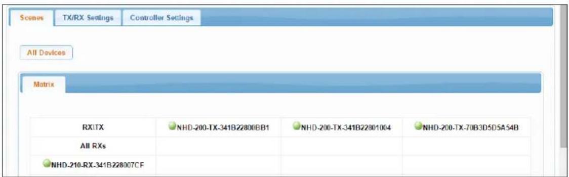

Device online

Device offline

A green bar represents corresponding TX and RX are connected.
Clicking the green bar changes colour to clear to signify the corresponding TX and RX are disconnected.

A red bar denotes TX/RX connection is being processed

A clear bar signifies corresponding TX and RX are not connected. Click to connect.
! To remove unwanted offline TX or RX units from the scene use the 'X' icon next to its name in the matrix or use the API command: config set device remove name (name is the alias or the device number).
ii. TX/RX Settings
The TX/RX Settings section enables IP settings and alias of each TX and RX to be configured as well as rebooting the system and factory resetting the devices.
Get started by selecting the device to be configured from the list displayed and configure options as below:
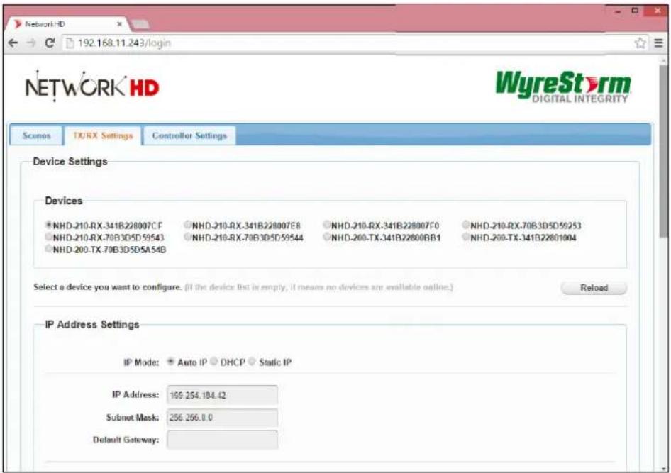
| GUI Element Description |
| Auto IP Obtain IP address automatically |
| DHCP IP address assigned by DHCP server |
| Static IP address manually configured |
| IP Address IP address of TX/RX |
| Subnet Mask Subnet mask of TX/RX |
| Default Gateway Default gateway of TX/RX. |
Encoder Setup
![Encoder Setup Rate Control: CBR VBR FixQP Avg bitrate: 40960 [2,40960] Profile: H.264 Baseline Profile H.264 Main Profile H.264 High Profile GOP: 60 [1,65535] FPS: 60 [1,60] Transport Type: RAW TS Apply](/content/2026/05/921877/images/7884e9cf4e50c88e19e879e3ecceb83b53890bd74df40a22c2712671ac54e4b5.jpg)
| GUI Element Description | ||
| Rate Control | CBR | Constant Bit Rate - Best used in systems where bandwidth is limited and must match exactly the calculated amount. |
| VBR Variable Bit Rate | - Best used for optimal quality/bandwidth usage trade off | |
| FixQP | Fixed Quantization Parameter - QP is an index used to derive a scaling matrix. Quantization in an H.264 encoder is controlled by a quantization parameter, QP, that ranges from 0 to 51. | |
| Avg Bitrate The bitrate that the encoder will inject into the network | ||
| Profile | The H.264 standard defines a sets of capabilities, which are referred to as profiles, targeting specific classes of applications. | |
| H.264 Baseline Profile | Primarily for applications that require low latency and additional data loss robustness, this profile is most suited for use in video conferencing applications. | |
| H.264 Main Profile | This profile is best used where a compromise between latency and quality is required. | |
| H.264 High Profile | This profile is useful particularly for high-definition/high quality applications where latency is not a concern. | |
| GOP: Group of Pictures | The GOP is a group of successive pictures within a coded video stream. From the pictures contained in it, the visible frames are generated. The higher the value the higher the image quality. | |
| FPS: Frames Per Second | The FPS rating is used to set the frequency at which the encode captures the video stream. The higher the value the higher the image motion quality. | |
| Transport Type | RAW transmits the H.264 bit stream without any container information. TS wraps the bit stream in an MPEG2 container. There is no difference in quality between the two settings. | |
Alias
! Changing the IP address of TX/RX devices requires a restart for the settings to take affect. Please use the reboot button at the bottom of TX/RX Settings page
Alias' can be used to make identification of system components easier e.g. TV12 or Bluray1. They can also be used instead of device identifiers in API commands.

| GUI Element Description |
| Alias Rename TX/RX alias for easier identification and use from API commands |
! Alias cannot contain any of the following symbols or combinations of letters/numbers: ',' ;' _ '@', '*', &', 'TX', 'RX', 'NHD'.
Commands

| GUI Element Description | |
| Factory Default Restore | CTL to factory default settings |
| Reboot Reboot CTL | |
| Shutdown Shutdown | CTL |
- CTL Settings contains the settings for the IP control box itself, comprising of two separate network connections for communication with RX/TX devices and communication to the PC/control system.
- Each setting must be on the same subnet as other devices to enable communication between all devices.
- The default Auto IP setting is recommended for RX & TX communication - devices will use Bonjour to discover each other
iii. CTL Settings
![Scenes TX/RX Settings Controller Settings IP Setup [TX and RX communication] IP Address: 169.254.1.1 Subnet Mask: 255.255.0.0 Default Gateway: 169.254.1.254 (Attention) After pressing "Apply", this IP control box will automatically reboot for the settings to take effect. Apply IP Setup [Teinet client and browser communication] IP Address: 192.168.11.243 Subnet Mask: 255.255.0.0 Default Gateway: 192.168.11.1 (Attention) After pressing "Apply", this IP control box will automatically reboot for the settings to take effect. Apply](/content/2026/05/921877/images/213d165437cba9c11edb642e130e79809d30dcf623d2589107d798e17485b3c8.jpg)
IP Setup (TX and RX communication)
![Scenes TX/RX Settings Controller Settings IP Setup [TX and RX communication] IP Address: 169.254.1.1 Subnet Mask: 255.255.0.0 Default Gateway: 169.254.1.254 (Attention) After pressing "Apply", this IP control box will automatically reboot for the settings to take effect. Apply](/content/2026/05/921877/images/6b576878465c61f0d85622433e32637a618fd61836c12f66b0e55fca0d97be35.jpg)
| GUI Element Description | |
| IP Address IP address for TX and RX communication | |
| Subnet Mask Subnet mask for TX and RX communication | |
| Default Gateway Default gateway for TX and RX communication |
IP Setup (Telnet/Browser communication)
![IP Setup [Telnet client and browser communication] IP Address: 192.168.11.243 Subnet Mask: 255.255.0.0 Default Gateway: 192.168.11.1 (Attention) After pressing Apply, this IP control box will automatically reboot for the settings to take effect. Apply](/content/2026/05/921877/images/e6710d2b959c6d154a639676afc026249210ced21e80b5b4d673a8c763e3f1f8.jpg)
| GUI Element Description | |
| IP Address IP address for Telnet client and web | |
| Subnet Mask Subnet mask for Telnet client and web | |
| Default Gateway Default gateway for Telnet client and web |
Web Password
Web Password
| GUI Element Description | |
| Web Password Login | password for Web UI management page |
| Default password “admin” can be used to restore to factory settings if the user password is unknown | |
Debug Log
Debug Log
ON OFF
Apply
Debug files can only be used with the guidance of WyreStorm support.
12. NetworkHD™ Console Configuration
Included in the download package is the Bonjour SDK installer. This must be installed prior to installing the NetworkHD Console software.
i. NetworkHD Console Software Installation
1 Download the latest installation package of the NetworkHD Console Software from wyrestorm.com and double-click Setup.exe to start the installation process. Complete the installation following the instructions in the installer package.
Your operating System must be Windows XP or later.
2 The NHD-100-TX & NHD-100-RX are configured by default to IP addresses in the range of 169.254.xxx.xxx, commonly referred to as Auto IP addresses. This is not a DHCP assigned address.
This addressing enables the NHD-000-CTL to automatically discover NHD TX & RX units without any configuration on any network. Changing an RX or TX devices IP settings will prevent this auto discovery and the system components will require a reset.
NOTE: The example below is based on operation using Windows 7 - steps may differ slightly depending on your operating system.
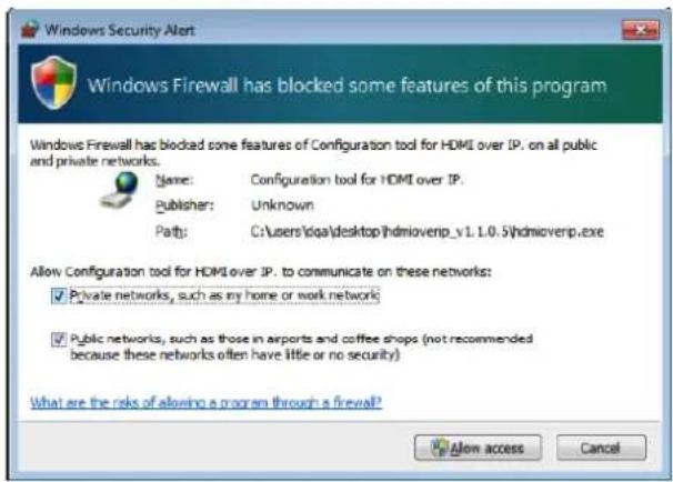
NetworkHD Console.exe is Windows only. For configuration from other operating systems the NHD-000-CTL must be used. If a 'Windows Security Alert' appears, check both boxes and click 'Allow access' (with Administration Authority).
3 Click Start menu, go to Control Panel > Network and Sharing center > Change Adapter Settings > Local Area Connection. Right click and choose Properties.

4 Highlight Internet Protocol Version 4 (TCP/IPv4) then click Properties.

5 Check Use the following IP address, for the IP address enter 169.254.xx.xx (if unsure use 169.254.2.5) Enter subnet mask number 255.255.0.0 Click OK, then click OK again.

ii. Searching for devices
1 Open the NetworkHD Console and click Search in the Device list area to begin the search – a green progress bar will illustrate process % remaining.

2 When the search is complete authenticated devices will be displayed in the Devices area. Restore is checked by default.

! If no devices are found, please refer to #1 of the Troubleshooting section of this guide.
iii. Setting Device Parameters
Right click a device in Devices - all available functions are displayed in the pop-up menu.

| Operation Description | |
| Config Configure device parameters - available only when a single device is selected. | |
| Video Settings Force resolution and change latency settings. | |
| Audio Settings This is inoperable with 100 series NetworkHD ^TM . | |
| Update | Incompatible with the 100 series of NetworkHD ^TM , please use the Maintain Tool available with firmware downloads. |
| Delete Delete devices - valid when one or more devices are selected. | |
| Turn on This is inoperable with 100 series NetworkHD ^TM . | |
| Mute This is inoperable with 100 series NetworkHD ^TM . | |
| Turn on OSD Incompatible with the 100 series of NetworkHD ^TM . | |
| Turn Off OSD Incompatible with the 100 series of NetworkHD ^TM . | |
| Background Settings This is inoperable with 100 series NetworkHD ^TM . | |
| Reset | Restore device to factory settings. After a factory Reset, it is recommended to press Delete and then Search to discover the device again. This may require you to change your computer IP address. |
| Reset EDID EDID Reset Extended Display Identification Data - valid when a TX device is selected. | |
| Restart | Restart device. |
iv. Device Settings
Right click a device in Devices and choose Modify, the Device settings dialog box is displayed.

| GUI Element Description | |
| Devices Current device | |
| Host Name ID Host Name ID - generated by the system and cannot be changed | |
| Alias User-defined device name containing a maximum of 80 characters | |
| IP Address Device IP address - can be set only when static mode is selected | |
| Subnet Mask Subnet mask for the device - can be set only when static mode is selected | |
| Auto Obtain IP address automatically | |
| DHCP IP address assigned by DHCP server in router or switch - This is not recommended | |
| Static | IP address is manually configured - if Static is chosen, enter 255.255.0.0 in Subnet Mask |
v. Creating Scenes
Scenes are preset configurations of routing that can be recalled at any time via the NetworkHD console or NHD-000-CTL.
1 Create a Scene: Click the Create button to create a scene with the required number of displays eg. 2 x 2 for 4 displays – the name of the scene must be unique.
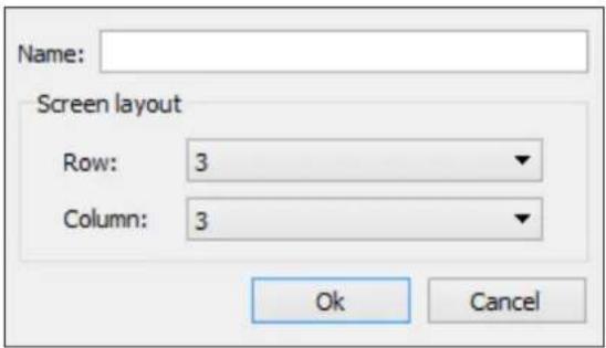
Click OK and details of the 2 x 2 scene will appear in the window.
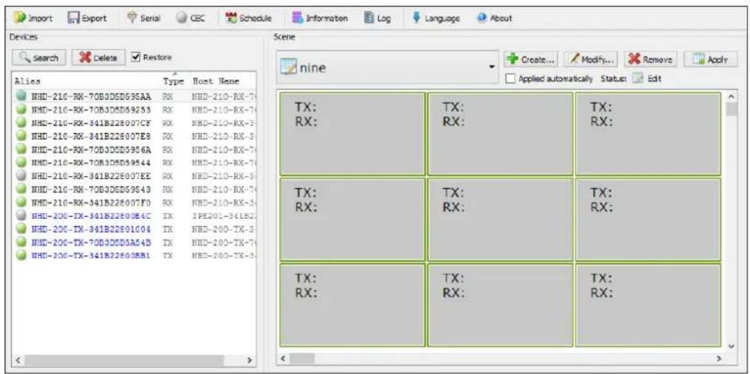
Drag & Drop the Encoders and Decoders from the left hand menu into the right hand boxes. And Click Apply to test your configuration.
Please note that although an encoder can be used multiple times within a scene, decoders can only be used once.

vi. Configuration File Management
Click Export to save the configuration file to a specified directory. When exporting please select the Configuration Information for export to the NHD-000-CTL.
Click Import to import the configuration file from a directory.
vii. Serial Control
NetworkHD™ 100 Encoders and Decoders can send RS-232 commands to connected devices. To test sending RS-232 commands from one or many devices press the Serial button in the top menu so display the following screen.
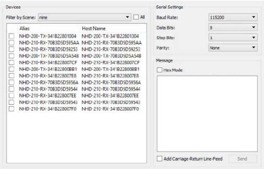
Select the Encoders or Decoders to receive the commands in the left hand menu and configure the appropriate serial settings for the receiving device in the top right section.
The required serial string can be entered in the white box ensuring that Hex mode and Carriage return are added if required.
viii. CEC Control
NetworkHD™ 100 decoders are able to turn on and off compatible displays using CEC through the HDMI cable.
Please note that CEC is not always compatible with every display – particularly older models. CEC may also not be enabled by default in your display. Different brands also label CEC control in different ways, please check with your display manufacturer if CEC & One Touch Play is supported.
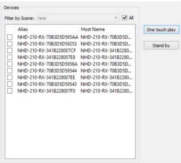
To turn on and off your compatible display simply select the decoder in the left hand menu and press the One Touch Play button to turn on and Standby to turn off.
x. Viewing the Encoders Preview Stream
To view the preview stream you require a video decoder capable of supporting CIF formatted material from a Motion-JPEG feed. For best results the renderer should be able to reformat the aspect ratio as CIF formatting can change the aspect ratio of the original content.
WyreStorm highly recommends VLC on all devices for playback.
Simple Stream URL:
In VLC Select Open Network Stream... from the File menu. In the URL bar enter:
http://NHD-100-TX-IP-address/stream
For example:
http://169.254.115.197/stream
Press Open.

To correct the aspect ratio of the feed adjust the "Aspect Ratio" options that are available from the "Video" menu.
The log records the tool operation and device communication information, which can be used for troubleshooting.
2014-03-17 00:02:29 - read param name="vw_moninfo_ht", value="vw_moninfo_ht" not defined.
2014-03-17 00:02:29 - Device('EX131-34IB2280007Z') send data succeed [/astparam g vw_moninfo_va]
2014-03-17 00:02:29 - Device('EX131-34IB2280007Z') recv data ["vw_moninfo_ht" not defined/usr/local/bin # ./astparam g]
2014-03-17 00:02:29 - Device('EX131-34IB2280007Z') recv data ["vw_moninfo_ht" not defined/usr/local/bin # ./astparam g vw_moninfo_va
"vw_moninfo_va" not defined/usr/local/bin # ]
2014-03-17 00:02:29 - read param name="vw_moninfo_va", value="vw_moninfo_va" not defined.
2014-03-17 00:02:29 - Device('EX131-34IB2280007Z') send data succeed [/astparam g vw_moninfo_vt]
2014-03-17 00:02:29 - Device('EX131-34IB2280007Z') recv data ["vw_moninfo_va" not defined/usr/local/bin # ./astparam g ]
2014-03-17 00:02:29 - Device('EX131-34IB2280007Z') recv data ["vw_moninfo_va" not defined/usr/local/bin # ./astparam g vw_moninfo_vt
"vw_moninfo_vt" not defined/usr/local/bin # ]
2014-03-17 00:02:29 - read param name="vw_moninfo_vt", value="vw_moninfo_vt" not defined.
2014-03-17 00:02:29 - Device('EX131-34IB2280007Z') send data succeed [/astparam g vw_v_shift]
2014-03-17 00:02:29 - Device('EX131-34IB2280007Z') recv data ["vw_moninfo_vt" not defined/usr/local/bin # ./astparam g ]
2014-03-17 00:02:29 - Device('EX131-34IB2280007Z') recv data ["vw_moninfo_vt" not defined/usr/local/bin # ./astparam g vw_v_shift
"vw_v_shift" not defined/usr/local/bin # ]
2014-03-17 00:02:29 - read param name="vw_v_shift", value="vw_v_shift" not defined.
2014-03-17 00:02:29 - Device('EX131-34IB2280007Z') send data succeed [cat /sys/devices/platform/display/monitor_info]
2014-03-17 00:02:29 - Device('EX131-34IB2280007Z') recv data ["vw_v_shift" not defined/usr/local/bin # cat /sys/device]
2014-03-17 00:02:30 - Device('EX131-34IB2280007Z') recv data ["vw_v_shift" not defined/usr/local/bin # cat /sys/devices/platform/display/monitor_info attached=n
[/usr/local/bin # ]
2014-03-17 00:02:30 - Device('EX131-34IB2280007Z') is updated.
2014-03-17 00:02:30 - All devices are updated.
2014-03-17 00:02:30 - Start restoring scene...
2014-03-17 00:02:30 - The scene is restored.
2014-03-17 00:02:30 - The search is complete.
13. Additional Information
Further information about NetworkHD™ including system configuration guides and Enado templates can be found at wyrestorm.com
14. NetworkHD™ Control Protocol
The Telnet protocol can be used to send configuration settings, matrix switching and video wall commands to the NetworkHD™ system.
Commands can only be issued to the NHD-000-CTL by IP using port 23.
The default IP address of the NHD-000-CTL is 192.168.11.243 – in default configuration commands should be sent to this IP address.
Matrix Switching Control
| Command | matrix set TX1 RX1 RX2, TX2 RX3 RX4,... |
| Return | matrix set: TX1 RX1 RX2, TX2 RX3 RX4,... |
| Note | Route one or Multiple TX on one or Multiple RX. Each individual TX and its routed RX or RX's compose a record, and should be separated by a commas. Use NULL after a TX and any RX units from this TX will disconnect. Matrix commands cannot be sent when an RX is in video wall mode, first remove the RX from the video wall or use the vw change commandE.g.: "matrix set Source1 Screen1 Screen2" sends TX with alias Source1 to RX's with alias' Screen1 & Screen2 |
| Command | matrix get |
| Return | the connected TX/RX information with below formatmatrix information:TX1 RX1TX2 RX3TX2 RX4.... |
| Note | Obtain matrix information. Based on current TX/RX in the network, re-construct the network topology andfeedback to the third-party controller. |
Activate Scene
| Command | scene active scenename |
| Return | scene scenename active success |
| Note | Active a certain scene.E.g.: 'scene active VidWall-SettopBox" |
Serial
Pass-through the serial commands.
| Command | serial -b param -r {on|off} -h {on|off} “command-string” hostname1 hostname2 ... |
| Return | serial command received:serial -b param -r {on|off} -h {on|off} “command-string” hostname1 hostname2 ... |
| Note | Configure devices hostname1, hostname2 to pass a serial command. Command-strings cannot contain “&”.-b param, configure the RS-232 format of the peripheral, Baud rate, Data bits, Parity and Stop bits. E.g.: -b 115200-8n1.-r {on|off}, to turn on & off Carriage Return following the command-string.-h {on|off}, to turn on & off hex. hostname1 hostname2 ..., indicates the destination, could be multiple.E.g.: “serial -b 9600-8n1 -r on -h off “PWR01” Screen1 Screen2 Screen3” Sends the ASCII command “PWR01” to Screens 1, 2 & 3 with a carriage return at 9600 baud – 8 data bits, No parity, 1 Stop bit. |
CEC
Pass-through the CEC commands.
| Command | config set device cec standby RX1 RX2 ... |
| Return | config set device cec standby hostname1 hostname2 ... |
| Note | Set the display which is connected to RX device to standby mode. The display must support CEC control.E.g.: “config set device cec standby Screen1” |
| Command | config set device cec onetouchplay RX1 RX2 ... |
| Return | config set device cec onetouchplay hostname1 hostname2 ... |
| Note | Turn on the display which is connected to the RX device. The display must support CEC control.E.g.: “config set device cec onetouchplay Screen1” |
15. Troubleshooting
1) If NetworkHD™ Software Console cannot find any devices on the network - If following the network settings advice in sections 10 through 14 above does not yield any devices, check your Windows Firewall settings. Using Windows 7 as an example (Other versions of Windows may differ):
- Click Start menu, go to Control Panel > System and Security > Windows Firewall > Allowed Programs, highlight NetworkHDconsole.exe, check Home/Work (Private) and Public.

- Check the IP address and subnet mask of the PC. The network segment for IP address is 169.254.x.x and the subnet mask is 255.255.0.0, the PC and encoder/decoder should be in the same network segment. (See section 11.)
- Check the settings of the switch match those in the Switch Configuration Guides available from wyrestorm.com
- Ensure that the Bonjour SDK software has been installed on the machine you are using - the installer is available in the NetworkHD™ software console installation file.
2) If you are unable to access the web management UI
- Check the IP address of your computer. The default IP address of the IP Control Box is 192.168.11.243, so the IP address of the computer should be 192.168.11.xxx.
- Check the Web browser. We recommend you use Firefox, Opera, Safari Internet Explorer 11 or Chrome. If the problem persists, try to upgrade you browser to the latest version.
- Perform a reset on the NHD-000-CTL by holding down the reset button on the front of the device.
3) If no devices appear in the Matrix or TX/RX Settings page...
- Ensure the devices are powered up and connected to the same network
- Ensure that the network settings in the router are correct for those set in the RX/TX units
- Refresh the browser
- Reboot all system components including the NHD-000-CTL
- Perform a reset on the NHD-000-CTL by holding down the reset button on the front of the device
4) If you cannot set a device Alias...
A device may have previously been connected to the NHD-000-CTL with that Alias.
You will need to factory reset the CTL for it to lose that alias, be aware of alias conflicts if that other device is still connected but powered down.
5) If the decoder device continuously reboots...
The decoder is set to DHCP but it cannot find a DHCP server. You must connect the unit to a DHCP server so that it can finishing initializing. You will then be able to change the IP settings.
6) If you are unable to connect to the web interface of the NHD-000-CTL:
- Ensure that the Ethernet switch is configured as per the switch configuration guides at wyrestorm.com (You may need to disconnect all encoder devices from the switch in order to regain network connection.)
- Ensure that you computer IP address is in the same subnet as the NHD-000-CTL (by default 192.168.11.xxx)
7) If you do not see an image on the display:
- Screen message shows "waiting for Encoder" or "waiting for video source" - the encoder is offline or the source has turned off/entered standby. Check TX or source device is powered and switched on
- Screen is completely blank - check display is on and correct input is selected, ensure the RX is powered and the lights are stable on the front. Replace the HDMI cable for a cable tested fully working
- Only part of the Image is displayed - the device is in "video wall mode". Send a command to exit the device from video.
Note: be aware of alias conflicts if devices are still connected but powered down.
8) If the IP address settings of the NHD-100-TX & RX devices are not taking please reboot them after making the settings.
9) If the video or audio is distorted please reboot both the source device and the encoder.
16. FAQ
What compression technology is utilised in NetworkHD™?
NetworkHD™ utilises high quality H.264 compression algorithm to produce very high quality images that are indistinguishable from the original at normal viewing distances.
What resolution audio & Video does NetworkHD™?
NetworkHD™ supports up to full HD 1080P HDMI video inputs and high quality stereo audio.
How many Decoder & Encoder units can I use in a NetworkHD™ system?
NetworkHD ^™ is a highly scalable system tested with up to 1000 encoder/decoder devices.
17. Maintenance
Clean this unit with a soft, dry cloth only. Never use alcohol, paint thinner or other harsh chemicals.
18. Provided Service
-
Damage requiring service: This unit should be serviced by a qualified service personnel if:
-
The power supply or AC adaptor has been damaged.
- Objects or liquid have gotten into the unit.
- The unit has been exposed to rain.
- The unit does not operate normally or exhibits a marked change in performance.
-
The unit has been dropped or the cabinet damaged.
-
Servicing Personnel: Do not attempt to service the unit beyond that described in these operating instructions. Refer all other servicing to authorised servicing personnel.
- Replacement Parts: When parts need replacing, ensure parts approved by the manufacturer are used – either those specified by the manufacturer or parts possessing the same characteristics as the original parts. Be aware – unauthorized substitutes may result in fire, electric shock, or other hazards and will invalidate your warranty.
- Safety Check: After repairs or service, ask the service personnel to perform safety checks to confirm the unit is in proper working condition. When shipping the unit, carefully pack and send it prepaid, with adequate insurance and preferably in the original packaging. Please include a document or letter detailing the reason for return and include a daytime telephone number and/or email address where you can be contacted.
19. Mail-in-service
When shipping the unit, carefully pack and send it prepaid, with adequate insurance and preferably in the original packaging. Please include a document or letter detailing the reason for return and include a daytime telephone number and/or email address where you can be contacted.
If repair is required during the limited warranty period, the purchaser will be required to provide a sales receipt or other proof of purchase, indicating date and location of purchase as well as the price paid for the product. The customer will be charged for the repair of any unit received unless such information is provided.
20. Warranty
Should you feel your product does not function adequately due to defects in materials or workmanship, we (referred to as "the warrantor") will, for the length of the period indicated below (starting from the original date of purchase) either:
a) Repair the product with new or refurbished parts.
or
b) Replace it with a new or refurbished product.
Limited warranty period:
All Wyrestorm products are covered by a 3 year PARTS and LABOUR warranty. During this period there will be no charge for unit repair, replacement of unit components or replacement of product if necessary.
The decision to repair or replace will be made by the warrantor. The purchaser must mail-in the product during the warranty period. This limited warranty only covers the product purchased as new and is extended to the original purchaser only. It is non-transferable to subsequent owners, even during the warranty period.
A purchase receipt or other proof of original purchase date is required for the limited warranty service.
21. Warranty Limits & Exclusions
1. This Limited Warranty ONLY COVERS failures due to defects in materials or workmanship and DOES NOT COVER normal wear and tear or cosmetic damage.
The limited warranty also DOES NOT COVER damage that occurs in shipment or failures caused by products not supplied by the warrantor, failures resulting from accident, misuse, abuse, neglect, mishandling, misapplication, alteration, incorrect installation, set-up adjustment, implementation of/to consumer controls, improper maintenance, power line surge, lightening damage, modification, service by anyone other than a manufacturer-approved service centre or factory-authorised personnel, or damage attributable to acts of God.
- There are no express warranties except as listed under “limited warranty coverage.” The warrantor is not liable for incidental or consequential damage resulting from the use of this product or arising out of any breach of this warranty. For example: damages for lost time, the cost of having a person/persons remove or re-install previously installed equipment, travel to and from service location, loss of or damage to media, images, data or other recorded/stored.
22. Disclaimer
WYRESTORM PUBLICATION DISCLAIMER
The material contained in this document consists of information that is the sole property of WyreStorm. This document is intended to provide information to allow interfacing to the relevant WyreStorm equipment by third party products.
WYRESTORM IS NOT RESPONSIBLE FOR MALFUNCTIONS AND/OR THE IN-OPERABILITY WHICH MAY BE CAUSED BY THE APPLICATION OF THIS INFORMATION, WHETHER EXPECTED OR NOT.
WyreStorm reserves the right to change software, control codes and specifications without notice.
WyreStorm will not be liable for any use of this information or any changes it may make to those products. The use of this information constitutes an agreement by the user to these limitations and exclusions.
23. Installation Reference Logs
Encoder
| 25 | 24 | 23 | 22 | 21 | 20 | 19 | 18 | 17 | 16 | 15 | 14 | 13 | 12 | 11 | 10 | 9 | 8 | 7 | 6 | 5 | 4 | 3 | 2 | 1 | |
| Zone | |||||||||||||||||||||||||
| Group | |||||||||||||||||||||||||
| Screen No. | |||||||||||||||||||||||||
| Display Type | |||||||||||||||||||||||||
| TX Mac Address | |||||||||||||||||||||||||
| Tested Cable Length | |||||||||||||||||||||||||
| Switch No. | |||||||||||||||||||||||||
| Port No. | |||||||||||||||||||||||||
| Power Light on TX | |||||||||||||||||||||||||
| Power to Source | |||||||||||||||||||||||||
| Picture on Test Monitor | |||||||||||||||||||||||||
| Highest Pos. Res. Set on Source | |||||||||||||||||||||||||
| Auto Power off Disabled | |||||||||||||||||||||||||
| Alias Set for Decoder | |||||||||||||||||||||||||
| Visible on CTL |
INSTALLATION REFERENCE LOGS
| 25 | 24 | 23 | 22 | 21 | 20 | 19 | 18 | 17 | 16 | 15 | 14 | 13 | 12 | 11 | 10 | 9 | 8 | 7 | 6 | 5 | 4 | 3 | 2 | 1 | |
| Zone | |||||||||||||||||||||||||
| Group | |||||||||||||||||||||||||
| Screen No. | |||||||||||||||||||||||||
| Display Type | |||||||||||||||||||||||||
| RX Mac Address | |||||||||||||||||||||||||
| Tested Cable Length | |||||||||||||||||||||||||
| Switch No. | |||||||||||||||||||||||||
| Port No. | |||||||||||||||||||||||||
| Power Light on RX | |||||||||||||||||||||||||
| Power to Display | |||||||||||||||||||||||||
| Picture on Test Monitor | |||||||||||||||||||||||||
| Overscan Disabled on Screen | |||||||||||||||||||||||||
| Auto Power off Disabled | |||||||||||||||||||||||||
| CEC Enabled | |||||||||||||||||||||||||
| Alias Set for Decoder | |||||||||||||||||||||||||
| Visible on CTL | |||||||||||||||||||||||||
| 50 | 49 | 48 | 47 | 46 | 45 | 44 | 43 | 42 | 41 | 40 | 39 | 38 | 37 | 36 | 35 | 34 | 33 | 32 | 31 | 30 | 29 | 28 | 27 | 26 | |
| Zone | |||||||||||||||||||||||||
| Group | |||||||||||||||||||||||||
| Screen No. | |||||||||||||||||||||||||
| Display Type | |||||||||||||||||||||||||
| RX Mac Address | |||||||||||||||||||||||||
| Tested Cable Length | |||||||||||||||||||||||||
| Switch No. | |||||||||||||||||||||||||
| Port No. | |||||||||||||||||||||||||
| Power Light on RX | |||||||||||||||||||||||||
| Power to Display | |||||||||||||||||||||||||
| Picture on Test Monitor | |||||||||||||||||||||||||
| Overscan Disabled on Screen | |||||||||||||||||||||||||
| Auto Power off Disabled | |||||||||||||||||||||||||
| CEC Enabled | |||||||||||||||||||||||||
| Alias Set for Decoder | |||||||||||||||||||||||||
| Visible on CTL |
WyreStorm®
wyrestorm.com
WyreStorm Offices
North America Office: Tech Valley Park, 23 Wood Road, Round Lake, NY 12151 USA
Tel: +1 518-289-1293
EMEA Office: Unit 22, Ergo Business Park, Swindon, Wiltshire, SN3 3JW, UK
Tel: +44 (0) 1793 230 343
WyreStorm Technical Support
US: +1 844-280-WYRE (9973)
UK:- +44 (0) 1793 230 343
Email: support@wyrestorm.com
WyreStorm Technologies reserve the right to change physical appearance or technical specification of this product at any time.
Visit wyrestorm.com for the latest information on products..
150820


- WyreStorm HD over IP Solutions
- Instruction Manual
- Contents
- Introduction
- Features
- Safety Precautions
- WARNING
- In the Box
- NHD-100-TX
- NHD-100-RX
- NHD-000-CTL
- Before Installation
- Introduction
- Preparation
- Network Equipment & Switches
- Power
- Heat
- Software
- Redundancy
- Mounting/Installation
- Source & Display settings
- Testing & Certification
- Cable Type & 4K support
- Specifications
- Panel Description
- NHD-000-CTL Front
- NHD-000-CTL Rear
- NHD-100-TX Front
- NHD-100-TX Rear
- NHD-100-RX Rear
- Connection
- Ethernet Wiring Guide
- Typical Application
- i. One Encoder To One Decoder
- ii. One Encoder To Multiple Decoders
- Switch Settings & Requirements
- NHD-000-CTL Browser Configuration & Control
- i. Matrix Switching Commands
- ii. TX/RX Settings
- Encoder Setup
- Alias
- ! Changing the IP address of TX/RX devices requires a restart for the settings to take affect. Please use the reboot button at the bottom of TX/RX Settings page
- Commands
- iii. CTL Settings
- IP Setup (TX and RX communication)
- IP Setup (Telnet/Browser communication)
- Web Password
- Debug Log
- NetworkHD™ Console Configuration
- i. NetworkHD Console Software Installation
- ii. Searching for devices
- iii. Setting Device Parameters
- iv. Device Settings
- v. Creating Scenes
- vi. Configuration File Management
- vii. Serial Control
- viii. CEC Control
- x. Viewing the Encoders Preview Stream
- Simple Stream URL:
- http://NHD-100-TX-IP-address/stream
- http://169.254.115.197/stream
- Additional Information
- NetworkHD™ Control Protocol
- Serial
- CEC
- Troubleshooting
- 2) If you are unable to access the web management UI
- 3) If no devices appear in the Matrix or TX/RX Settings page...
- 4) If you cannot set a device Alias...
- 5) If the decoder device continuously reboots...
- 6) If you are unable to connect to the web interface of the NHD-000-CTL:
- 7) If you do not see an image on the display:
- FAQ
- What compression technology is utilised in NetworkHD™?
- What resolution audio & Video does NetworkHD™?
- How many Decoder & Encoder units can I use in a NetworkHD™ system?
- Maintenance
- Provided Service
- Mail-in-service
- Warranty
- Limited warranty period:
- Warranty Limits & Exclusions
- This Limited Warranty ONLY COVERS failures due to defects in materials or workmanship and DOES NOT COVER normal wear and tear or cosmetic damage.
- Disclaimer
- WYRESTORM PUBLICATION DISCLAIMER
- WYRESTORM IS NOT RESPONSIBLE FOR MALFUNCTIONS AND/OR THE IN-OPERABILITY WHICH MAY BE CAUSED BY THE APPLICATION OF THIS INFORMATION, WHETHER EXPECTED OR NOT.
- Installation Reference Logs
- WyreStorm®
- WyreStorm Offices
- WyreStorm Technical Support
Brand : WyreStorm
Model : NHD-100-RX
Category : Digital decoder