
GW18343VT - Intercom Gewiss - Free user manual and instructions
Find the device manual for free GW18343VT Gewiss in PDF.


| Product Type | Video entryphone (audio/video intercom) |
| Brand | Gewiss |
| Model | GW18343VT |
| Display | 3.5" TFT LCD color, 320x240 pixels |
| Dimensions (LxHxD) | 150 x 158 x 43 mm (including plate) |
| Weight | 0.33 kg |
| Power Supply | Power over LAN (PoL) 14.4V DC SELV |
| Current Consumption | 200 mA standby, 240 mA communication, max 250 mA |
| Communication | Ethernet LAN, max 100 Mbps, full duplex audio |
| Controls | 6 front push buttons (door opener, camera, navigation, privacy, answer) |
| Key Functions | Intercom, video mail, call transfer, privacy, baby monitoring, hands-free, business office, auxiliary relay |
| Ringtones | 10 melodies, adjustable volume with 9 levels |
| Video Mail Memory | Up to 20 messages, 30 sec each |
| Installation | Flush-mounting (box GW24237) or wall-mounting |
| Inputs | 1 auxiliary contact for local push-button |
| Outputs | 1 relay output (NO, 24V AC/DC, 3A max) |
| Connections | RJ45 port for LAN, extractable screw terminal |
| Compliance | IP20, operating temp 0°C to +45°C, storage -15°C to +70°C |
| Standards | EMC 2004/108/EC, EN 61000-6-1, EN 61000-6-3 |
| Maintenance | Clean with dry cloth; no abrasive products |
| Included Accessories | Terminal block, fixing screws, wall plugs, plate, manual |
Frequently Asked Questions - GW18343VT Gewiss
User questions about GW18343VT Gewiss
0 question about this device. Answer the ones you know or ask your own.
Ask a new question about this device
Download the instructions for your Intercom in PDF format for free! Find your manual GW18343VT - Gewiss and take your electronic device back in hand. On this page are published all the documents necessary for the use of your device. GW18343VT by Gewiss.
USER MANUAL GW18343VT Gewiss
natural_image
Black-and-white photo of a smiling woman in front of a digital display (no visible text or symbols)natural_image
Icon of a stylized speech bubble inside a circular frame, no text or symbols presentFigura 1
natural_image
Simple icon of a person standing inside a door, enclosed in a circular frame (no text or symbols)Figura 2
natural_image
Diagram showing internal components of an electronic device with no visible text or symbolsnatural_image
Technical line drawing showing three views of a device panel with mounting holes and internal components (no text or symbols)natural_image
Diagram of a computer monitor front panel with indicator lights and ports (no text or symbols)Control positions and functions 78
Information regarding the screen 80
USER INSTRUCTIONS 82
Answering a call 82
Making adjustments during the call 83
Call priorities 83
Menu 84
Stored parameter 85
Setting the date and time 85
Standard configuration 85
Loudspeaker volume 87
Calls: setting the volume and choosing the ringtone 89
Feedback buttons beep 91
Intercom call 92
Making an intercom call 93
LED signalling 95
Terminating the intercom call 95
Camera view 96
Visualising the images from all the telecameras 96
Visualising the images from a specific telecamera 97
Listening during camera view 98
Opening the door 98
Video mail 98
Enabling or disabling the video mail 99
Recording a video message 99
Viewing a video message 100
Deleting a video message 102
Deleting all the video messages 103
INDEX
Privacy 104
Excluding a call 104
Accepting calls 105
Call transfer 106
Enabling a call transfer 107
Disabling a call transfer 108
Baby monitoring function 109
Activating the remote baby monitoring function 109
Deactivating the remote baby monitoring function 110
Hands free function 110
Enabling or disabling the hands free function 110
Business office function 111
Setting the range time 112
Enabling the business office function 113
Disabling the business office function 114
Auxiliary services
Activating an auxiliary service (relay)
Maintenance
115
115
117
INSTALLATION INSTRUCTIONS 118
Correct position 118
Warnings for installation 118
Connection diagram 119
Switch connection 119
Direct connection to the front door unit 119
Connectors position 120
Electric connections 120
Direct RJ45 - RJ45 LAN network cable wiring diagram 121
Indirect RJ45 - RJ45 LAN network cable wiring diagram 122
Fixing and completion 123
Flush-mounting video entryphone 123
Wall-mounting video entryphone 123
Configuration 124
Logic connection between front door unit push-button and video entryphone 124
Setting the functions and parameters 127
Language 127
FDU door status 128
Switching off the screen 129
Inside/outside intercom 130
Relay management 133
Other parameters to be configured 134
Customising the menu items 135
How to modify a name 135
Customising a name 136
The resident's name 138
Identification data 140
Resetting the factory configuration 141
Resetting the video entryphone 142
TECHNICAL DATA 143
GENERAL WARNINGS
Warning! The safety of this appliance is only guaranteed if all the instructions given here are followed scrupulously.
These should be read thoroughly and kept in a safe place.
Chorus products can be installed in environments which are dust-free and where no special protection against the penetration of water is required.
They shall be installed in compliance with the requirements for household devices set out by the national standards and rules applicable to low-voltage electrical installations which are in force in the country where the products are installed, or, when there are none, following the international standard for low-voltage electrical installations IEC 60364, or the European harmonization document HD 60364.
Gewiss sales organization is ready to provide full explanations and technical data on request.
Gewiss S.p.A. reserves the right to make any necessary modifications to the product described in this manual, at any time and without forewarning.
Pack Contents
1 video entryphone with speakerphone - flush-mounting or wall-mounting
1 extractable terminal block
4 fixing screws (GW 18 341 xx)
2 wall plugs (GW 18 343 xx)
2 fixing screws (GW 18 343 xx)
1 plate (VT = titanium, VA = slate, TB = white)
1 User and Installation Manual
Briefly
The video entryphone with speakerphone - flush-mounting and wall-mounting is a device that allows you to establish a 2-way audio communication (full duplex) and visualise - on the LCD colour screen (3.5" TFT) - the images filmed either by the audio-video module for front door units (GW 18 301, GW 18 302), or by the video control telecameras connected to the video entryphone system. When there is no activity (communication, menu navigation), the screen switches off automatically after a prefixed standby time.
The incoming calls - primary and secondary front door units, landing and intercom calls - can be distinguished by choosing from 10 different ringtones. The melodies volume has 9 adjustment steps, thanks to a scroll bar.
The video entryphone has 6 command buttons for the following functions: door opener, video control, menu navigation, privacy, and call answering.
With the aid of a handy menu, you can configure the video entryphone and access the following functions: intercom call between apartment units (the same apartment, between different apartments and with switchboard), video control, video mail, privacy, call transfer, office, free hands, baby monitoring, and activation of relay outputs.
Apart from the RJ45 port for connecting the Ethernet switch (GW 18 371) ^1 , the device also has an input for a local push-button (call from door lock) and a relay output for local implementation.
The video entryphone can be wall-mounting (GW 18 343 xx) or flush-mounting (GW 18 341 xx) with the relevant box (GW 24 237).
GENERAL DESCRIPTION
Control positions and functions

KEY
- Speaker and microphone
- Intercommunication LED 1
- Intercommunication LED 2
- Intercommunication LED 3
- Intercommunication LED 4
- LCD colour screen
- “Door opener” key ☐ activates the electro-lock of the front door unit, with or without a call in progress. If pressed without any video entryphone call in progress, and with the screen switched on, only the electro-lock of the primary (predefined) front door unit will be activated (if this is enabled via the relevant DIP switch on the front door unit).
GENERAL DESCRIPTION
- “Camera view” / “Esc” key :visualises the images from the telecameras of the outside audio/video call positions, even without any call in progress. If there are any camera interfaces (GW 18 376), you can visualise their telecameras in both cyclical and fixed selection mode. When navigating in the menu, this key allows you to quit the current page and go back to the previous one.
- “Navigation Up” key : used to move the cursor upward, or if properly configured, to activate an auxiliary service or the lock of the secondary front door unit.
- “Navigation Down” key ▼: used to move the cursor downward, or if properly configured, to activate an auxiliary service or the lock of the secondary front door unit.
- “Privacy” / “Enter” key ⚙: allows you to enable and disable the Privacy function and, during navigation, to select the item highlighted.
- “Answer” key (with LED) 📋 allows you to answer the call. The green LED flashes when a call is received, and the light remains steady while the communication is active. When the Privacy function is enabled, the LED has a steady red light; it flashes when the call transfer function is activated. The LED flashes alternatively red/green when there is a message in the answering machine that has not been viewed.
GENERAL DESCRIPTION
Information regarding the screen
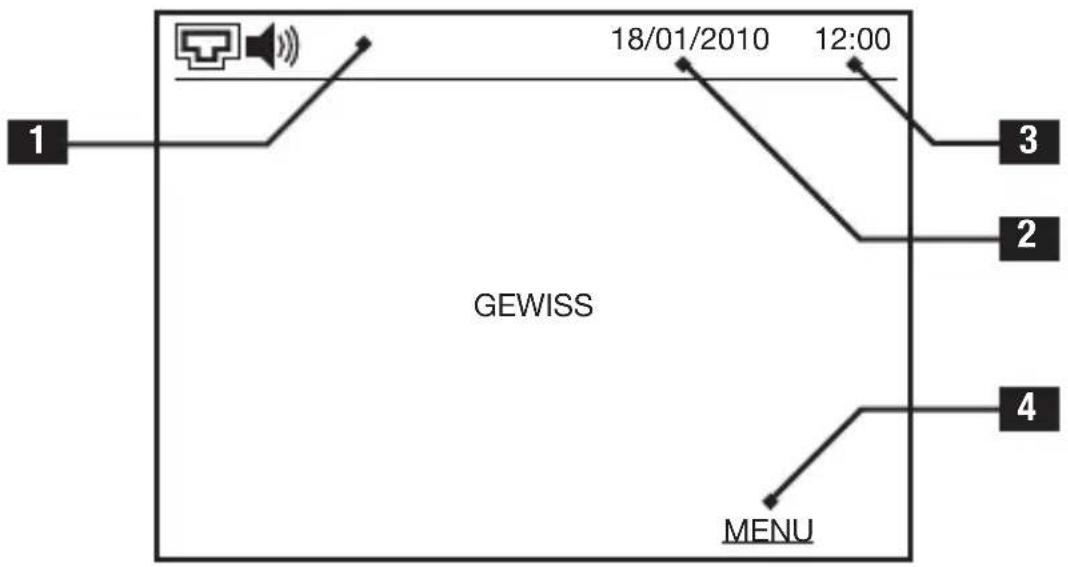
flowchart
graph TD
    A["1"] --> B["GEWISS"]
    B --> C["18/01/2010"]
    B --> D["12:00"]
    B --> E["3"]
    B --> F["2"]
    B --> G["4"]
    B --> H["MENU"]
KEY
- Status icons
 | System connection status:outside call position |
 | Indicates the loudspeaker volume (the level is indicated by the number of sound waves) |
 | Video messages stored. The number next to the icon indicates the number of non-visualised messages in the memory |
 | Privacy function enabled |
 | Call transfer function enabled |
GENERAL DESCRIPTION
 | Open door alarm: the door of the front door unit has been open for longer than 5 minutes (the electro-lock on the door must have been suitably connected, and the FDU door status function must be enabled) |
 | Hands free function enabled |
 | Business office function enabled |
- Current date
- Current time
- Function associated with the key
USER INSTRUCTIONS
Answering a call
The calls may arrive from:
filmed by the telecamera is immediately visualised, before any audio communication, and the green LED of the 📋 key flashes.
ATTENTION: if multiple video entryphones are installed in an apartment, the image is only shown on the main one (INTERCOM no.1) whereas on the other ones, the screen will remain off. Press any button key to activate the screen.

key flashes.
The display comes on, showing the image in figure 1.
LED on the 🔍 key flashes.
that identifies the call position flashes.

natural_image
Icon of a stylized document with a speech bubble, no text or symbols presentFigure 1
Outside call from audio module
natural_image
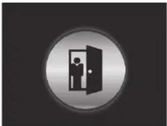
Simple icon of a person standing inside a door, enclosed in a circular frame (no text or symbols)Figure 2
Call from door lock
When you receive the call, you can:

the green key LED will stop flashing and become steady, and the 2-way audio communication can begin. During the conversation, you can press the 📋 button key to open the door, without interrupting the communication. Press the 📋 button key to interrupt the communication. The communication ends automatically after 120 seconds. Ten seconds before this, the green LED of the 📋 button key will begin flashing; if you press it again, the communication will be extended for a further 120 seconds.
USER INSTRUCTIONS
A priority is attributed to each type of call. When one call is in progress and another arrives with a higher priority, the current call is terminated to make way for the new one. For further details, refer to Call priorities.
Making adjustments during the call
You can access certain functions during the communication, by pressing ENTER.
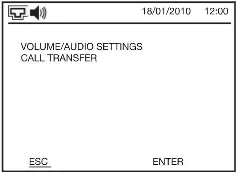
The menu will be superimposed on any image that may already be present.
For further information about these functions, refer to the relative paragraphs.
Call priorities
The video entryphone system manages the incoming calls according to the priority assigned to them.
The order of priority (from highest to lowest) is as follows:
- outside call position
- intercom call (inside or outside)
- call from door lock.
- camera view
When one call/conversation is in progress and another arrives with a higher priority, the current call/conversation is terminated to make way for the new one.
Menu

To access the menu, press the MENU key. If the screen is switched off (in standby), press any key to switch it on.
4 keys are needed to navigate the menus:


are entered, or an option is selected, a confirmation is given and you are taken back to the page of the previous menu.
menu; when data are entered, or an option is selected, you are taken back to the page of the previous menu without any modifications being memorised.
After the prefixed time of inactivity (30 seconds, 1 minute, or 3 minutes), the screen will switch off (standby) but it will memorise the last page visualised.
When the menu contains more items than can be visualised on a single page, the arrows will appear.
USER INSTRUCTIONS
Stored parameter
The video entryphone distinguishes the various menu items with colours and symbols:

in box: item selected
ty box: parameter stored
box: item not selected / parameter not stored.
In the screen example above, “AFTER 30 SECS.” is the parameter currently stored in the video entryphone, “AFTER 3 MINS.” is the item currently selected, and “AFTER 1 MIN.” is a non-selected item or a non-stored parameter.
Standard configuration
Setting the date and time

ATTENTION: the video entryphone does not automatically update the switchover from solar time to summer time and vice versa. It is therefore necessary to set these updates manually. If you do not do this, certain functions (such as the business office function) may not operate correctly.
To set the current date and time in the video entryphone, or to modify the display format, proceed as follows:
USER INSTRUCTIONS

On the main menu page, use the ▲ and ▼ keys to select SETTINGS, then confirm the selection with ENTER.

On the settings page, use the ▲ and ▼ keys to select the DATE/TIME SETTINGS item, then confirm the selection with ENTER.

On the date/time settings page, use the ▲ and ▼ keys to select the parameter you want to modify, then confirm the selection with ENTER.
USER INSTRUCTIONS
If you are modifying a format, use the
and keys to change the parameter visualised on the new page, then confirm the selection with ENTER.
The table below shows the possible options:
| Date format DD | /MM/YYYY date in | European format (day/month/year) |
| MM/DD/YYYY date in American format (month/day/year) | ||
| Time format 12 | HOURS time in Anglo-Saxon format (AM / PM) | |
| 24 HOURS time in European format | ||
If you are modifying the date or time, the currently set date/time will be visualised. The modifiable data item will flash. To modify it, use the ^ and ▼ keys, then confirm the selection with ENTER; each time you press ENTER, you will move on to the next data item. After modifying or confirming the last data item, the complete date and time will be stored and you will be taken back to the previous menu page.
Use the BACK key to move back; by pressing BACK several times, you can go back to the previous menu page without memorising any modifications made.
Loudspeaker volume
To set the volume of the loudspeaker, proceed as follows:

On the main menu page, use the ▲ and ▼ keys to select SETTINGS, then confirm the selection with ENTER.
USER INSTRUCTIONS

On the settings page, use the ▲ and ▼ keys to select VOLUME/AUDIO SETTING, then confirm the selection with ENTER.

On the volume/audio settings page, use the ▲ and ▼ keys to select SPEAKER VOLUME, then confirm the selection with ENTER.
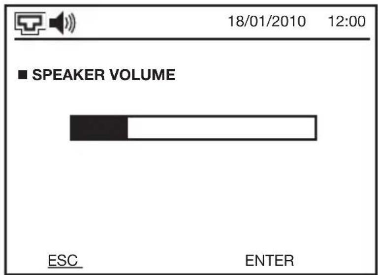
Use the ▲ and ▼ keys to set the speaker volume (shown graphically via a bar), then confirm the selection with ENTER.
Attention: the adjustment is only applied to the loudspeaker, not to the video entryphone microphone.
USER INSTRUCTIONS
Calls: setting the volume and choosing the ringtone
The video entryphone manages 5 different ringtones, so you can distinguish the type of call: primary outdoor call position, secondary outdoor call position, bell on landing, indoor and outdoor intercom call, call from switchboard.
To set the volume and choose between the various ringtones, proceed as follows:

On the main menu page, use the ▲ and ▼ keys to select SETTINGS, then confirm the selection with ENTER.

On the settings page, use the ▲ and ▼ keys to select VOLUME/AUDIO SETTING, then confirm the selection with ENTER.
USER INSTRUCTIONS

On the volume/audio settings page, use the ▲ and ▼ keys to select MELO-DIES VOLUME, then confirm the selection with ENTER.
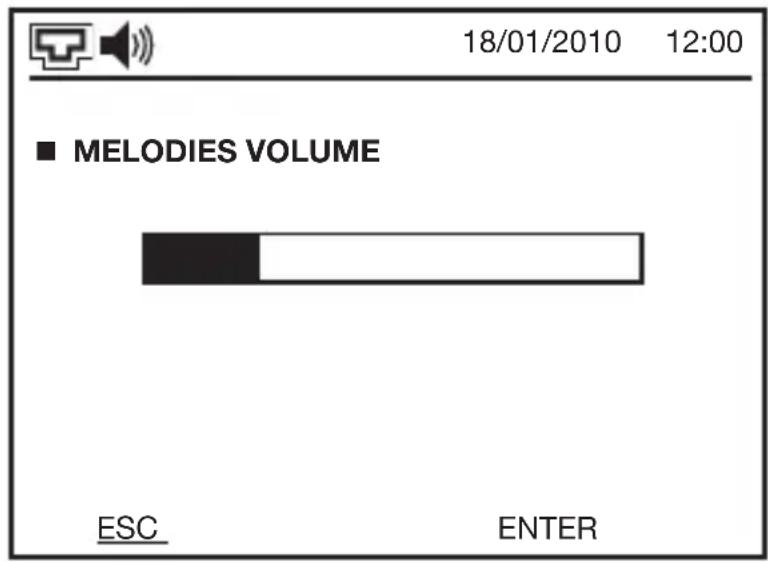
Use the ▲ and ▼ keys to set the melodies volume (shown graphically via a bar), then confirm the selection with ENTER.
The video entryphone will reproduce the ringtone for about 2 seconds, with the new volume level.

On the volume/audio settings page, use the ▲ and ▼ keys to select MELO-DIES SELECTION, then confirm the selection with ENTER. On the page that appears, you will see a list of the various types of call. Use the ▲ and ▼ keys to select the type of call you require, then confirm the selection with ENTER.
USER INSTRUCTIONS

The corresponding selection page will open (the example here shows the landing). The number identifies the type of ringtone set. Use the ^ and ▼ keys to change the type of ringtone: the visualised number will change and, at the same time, you will hear the sound of the new ringtone for 2 seconds. When you have found the required ringtone, confirm the selection with ENTER.
If you wish, you can also modify the other ringtones.
NB: different ringtones will help you to understand where the call is coming from, but several types of call can share the same ringtone if you prefer. It is even possible to apply a single ringtone to all the calls.
Feedback buttons beep
When you press a key, the video entryphone makes a confirmation beep. This sound can be enabled or disabled.
To enable or disable the feedback buttons beep, proceed as follows:

On the main menu page, use the ^ and ▼ keys to select SETTINGS, then confirm the selection with ENTER.
USER INSTRUCTIONS
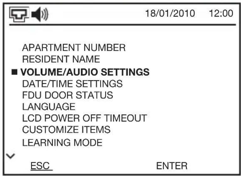
On the settings page, use the ▲ and ▼ keys to select VOLUME/AUDIO SETTING, then confirm the selection with ENTER.
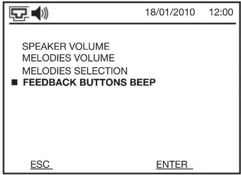
On the volume/audio settings page, use the ▲ and ▼ keys to select FEEDBACK BUTTONS BEEP, then confirm the selection with ENTER.
On the page that opens, use the ▲ and ▼ keys to select ENABLE or DISABLE, then confirm the selection with ENTER.
Intercom call
The video entryphone can establish a 2-way audio intercommunication (full duplex) with other devices (video entryphones, wall-mounting and flush-mounting entryphones, switchboard) of the video entryphone system.

ATTENTION: even if the intercommunication function is enabled between two video entryphones, the communication will always be audio only, because the video entryphones are not equipped with telecameras.
The inside intercom function is always available with any other positions in the apartment. The table below shows which calls can be made.
USER INSTRUCTIONS
| Position 1 Position 2 Position 3 Position 4 | ||||||
| Position 1 | ■ | ■ | ■ | |||
| Position 2 | ■ | ■ | ■ | |||
| Position 3 | ■ | ■ | ■ | |||
| Position 4 | ■ | ■ | ■ | |||
The outside intercom function is the one programmed between different apartments.
Making an intercom call
To make an intercom call, proceed as follows:

On the main menu page, use the ▲ and ▼ keys to select INTERCOM CALL, then confirm the selection with ENTER.

On the page of the intercom call, use the ▲ and ▼ keys to select the type of call you want to make:
the same apartment,
apartments.
switchboard (GW 18 392 software) installed in the system. Confirm the selection with ENTER.
USER INSTRUCTIONS

If you choose INSIDE, you will see a page listing the other apartment units of the apartment. If there are no other apartment units, the page will be empty.
NB: the general indications ROOM ... can be customised by the user to make them easier to recognise. For further information, refer to Customising the menu items.
Use the ▲ and ▼ keys to select the number to call, then press CALL.

If you choose OUTSIDE, a similar page will appear with a list of the apartments that you can call (up to 4).
NB: the general indications APARTMENT ... can be customised by the user to make them easier to recognise.
For further information, refer to Customising the menu items.
Use the ▲ and ▼ keys to select the number to call then press CALL.

If SWITCHBOARD was selected, a similar screen will appear; press the CALL button key to start the call.
When the intercom call is established, the green LED of the button key will light up.
USER INSTRUCTIONS
NB: if there is no answer after 20 seconds, the intercom call (inside or outside) will be terminated. If the device or apartment called is busy or has set the Privacy function, you will hear the “busy” tone and the “User busy” message will appear on the screen.
LED signalling
Above the LCD screen of the video entryphone, there are four intercommunicating LEDs which, in the event of an intercom call, provide the following information:
| LED OFF No information | |
| Fixed red LED The remote | apartment or device has activated the Privacy function |
| Flashing green LED The intercom call is in progress (the called device is ringing) | |
| Fixed green LED The called | apartment or device has answered |
Terminating the intercom call
To interrupt the intercom call, press the 🔔 key on the calling device when the green LED is lit up, or the END key on the answering device.
If neither form of interruption is made, the communication will be automatically terminated after 120 seconds. Ten seconds before this, the green LED of the button key will begin flashing; if you press it again, the communication will be extended for a further 120 seconds.

ATTENTION: the communication can only be extended by the person who answered the call, not by the person who made it.
USER INSTRUCTIONS
Camera view
From the video entryphone, you can observe the areas filmed by the telecameras installed in the system (front door units and telecameras possibly connected to camera interfaces), for monitoring purposes.
Visualising the images from all the telecameras
To visualise the images from the telecameras, proceed as follows:

With the screen ON, keep the key pressed for 3 seconds.

The image filmed by the telecamera of the outside call position will appear on the screen.
Use the ▲ and ▼ keys to switch to the other front door units or camera interfaces (GW 18 376), whose name will appear at the bottom left.
When switching to one of the front door units, the image of each telecamera remains visualised for 30 seconds, after which the video entryphone exits the camera view mode.
USER INSTRUCTIONS
When switching to a camera interface, the images of its telecameras change cyclically according to the settings of the camera interface itself (it is not possible to stop this cycle). To exit the camera view mode, press the 📋 button key again for 3 seconds.

ATTENTION: if you receive a call from a front door unit while in camera view mode, this mode will be automatically disabled to allow you to receive the call. It will be resumed when the call has ended.
Visualising the images from a specific telecamera
You can directly visualise the images from a specific telecamera (or from the telecameras of a specific camera interface, if installed) in the following way:

On the main menu page, use the ▲ and ▼ keys to select CAMERA VIEW, then confirm the selection with ENTER.

On the camera view page, use the ▲ and ▼ keys to select the telecamera you want to view, then confirm the selection with ENTER. NB: the general indications FRONT DOOR UNIT... can be customised by the user to make them easier to recognise. For further information, refer to Customising the menu items.
USER INSTRUCTIONS
On the screen, you will see the image filmed by the selected telecamera, whose name will appear at the bottom left.
When a telecamera is selected directly, it is no longer possible to scroll through the others via the ▲ and ▼ keys.
If a camera interface has been selected, the images from its telecameras will alternate cyclically, according to the time set on the camera interface itself.

ATTENTION: for the images filmed by the telecameras connected to a camera interface, there is no timing; for those from the front door units, there is a maximum time of 30 seconds before the camera view function is automatically terminated.
Listening during camera view
When an outside call position is selected, you can activate its microphone and listen to the sounds in the immediate vicinity. The microphone is activated using the

key, and remains active as long as the button key is kept pressed down.
The audio is automatically disabled when another apartment is called from the outside call position.
Opening the door
When an outside call position is selected, you can activate its electro-lock by pressing the ⏻ key, as long as the electro-lock of that position has been configured as "free".
Video mail
The Video mail function allows the person calling from an outside call position to leave a 30-second video message. The video entryphone can memorise up to 20 video messages. This function can be enabled or disabled by the user according to his needs.

ATTENTION: if several video entryphones have been installed in the apartment, only the main one (the first acquired during programming, and which you can recognise by the steady light on intercommunicating LED 1) is able to record the video messages.
USER INSTRUCTIONS
Enabling or disabling the video mail
To enable or disable the video mail, proceed as follows:

On the main menu page, use the ▲ and ▼ keys to select VIDEO MAIL, then confirm the selection with ENTER.

On the page of the video mail, use the ▲ and ▼ keys to select ENABLE or DISABLE, depending on whether you want to switch the video mail on or off, then confirm the selection with ENTER.
Attention: the video mail can also be enabled via the Call transfer function.
Recording a video message
When the video mail is enabled, if a call is not answered within the programmed clock time in the outside call position (even if the Privacy function is enabled), the visitor will hear the following message: "The user is busy at the moment. To record a video message, press the required apartment number again", and the words "RECORDING FROM FDU..." will appear on the screen.
While the video message is being recorded, it is possible to stop the recording and answer the call by pressing the 📋 button key (the key LED will have a steady green light).
USER INSTRUCTIONS

ATTENTION: if the video mail is activated from the Call transfer function, it will begin working at once, without waiting for a possible answer.
After the video message has been recorded, the 📋 icon will appear on the screen, next to the number of video messages not yet viewed, and the LED on the answer button key will flash alternatively red/green.

ATTENTION: the maximum number of video messages that can be recorded is 20.
Viewing a video message
To view a video message, proceed as follows:

On the main menu page, use the ▲ and ▼ keys to select VIDEO MAIL, then confirm the selection with ENTER.
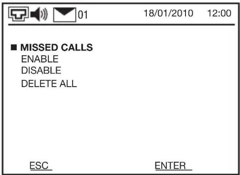
On the video mail page, use the ▲ and ▼ keys to select MISSED CALLS, then confirm the selection with ENTER.
USER INSTRUCTIONS

On the page showing the missed calls, there is a list of all the video messages stored (from the most recent to the oldest).
Each video message is identified by the date and time of the call (the date and time are those of the video entryphone).
If a message is preceded by the □ symbol, this means it has yet to be viewed, while ■ means it has already been viewed.
Use the ▼ and ▲ keys to select the required call, then confirm the selection with ENTER.
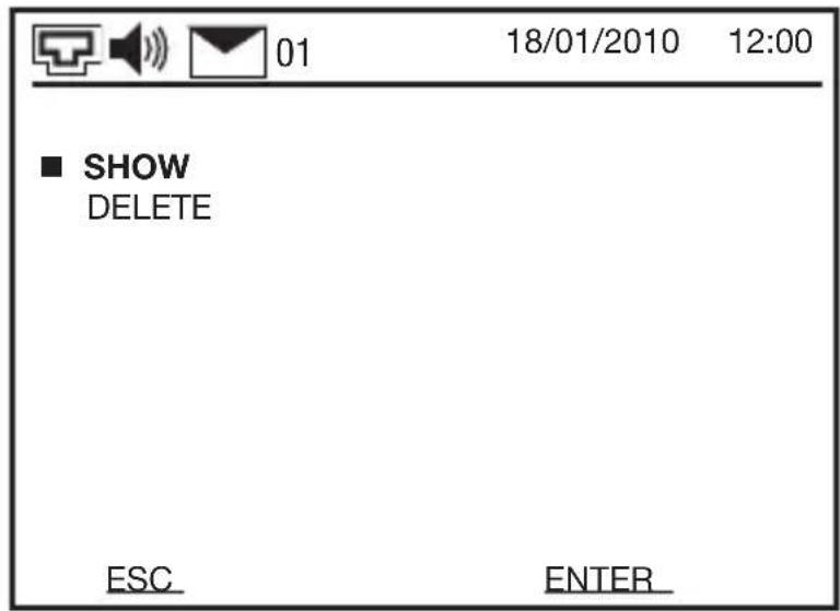
In the window that appears, select SHOW then confirm the selection with ENTER. To interrupt the viewing, press ESC.
USER INSTRUCTIONS
Deleting a video message

To delete a single video message, follow the same steps as for viewing a message, but when the screen alongside appears, select DELETE then confirm the selection with ENTER.
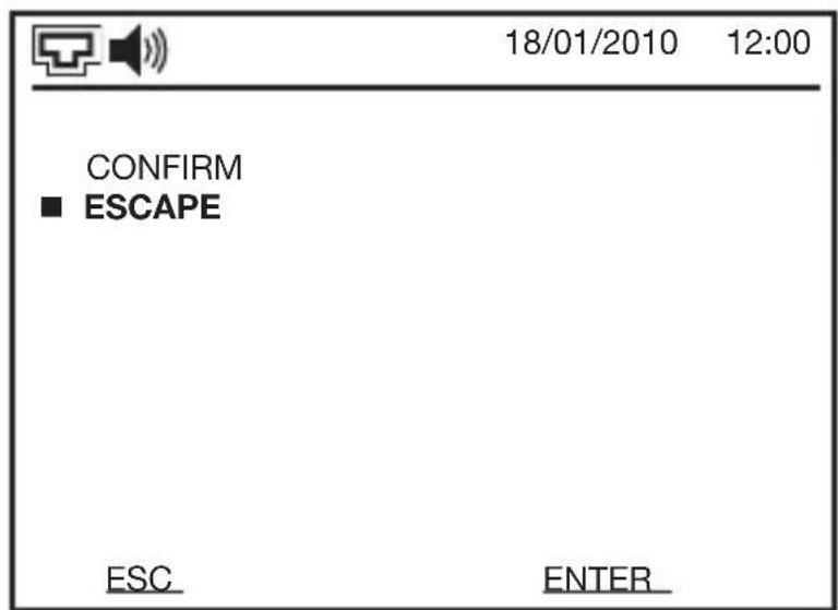
Select one of the following options on the page that is displayed:
message
without deleting the video message. Confirm the selection with ENTER.

ATTENTION: the deleting operation cannot be reversed. After deleting a video message, you cannot get it back.
USER INSTRUCTIONS
Deleting all the video messages
To delete all the video messages, proceed as follows:
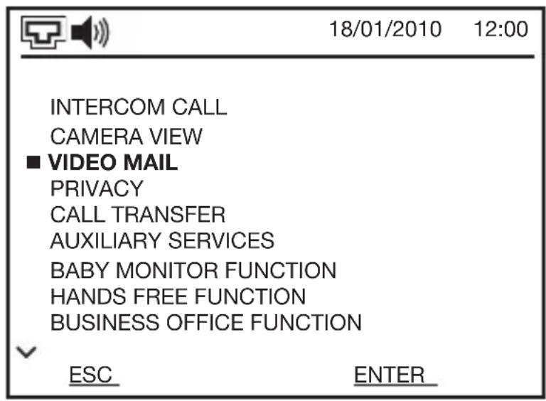
On the main menu page, use the ▲ and ▼ keys to select VIDEO MAIL, then confirm the selection with ENTER.

On the video mail page, use the ▲ and ▼ keys to select DELETE ALL, then confirm the selection with ENTER.

Select one of the following options on the page that is displayed:
video messages
without deleting the video messages. Confirm the selection with ENTER.
USER INSTRUCTIONS

ATTENTION: the deleting operation cannot be reversed. After deleting the video messages, you cannot get them back.
Privacy
With this function (also known as the privacy function), you can ensure the video entryphone does not receive calls from the front door unit or landing, or any intercom calls.
If the exclusion is activated from the main apartment unit (the first device acquired in the apartment, and which you can recognise by the steady light on intercommunicating LED 1), the entire apartment will be excluded. If the function is activated from one of the other apartment units however, the apartment can be contacted (although not from the excluded positions).
With the Privacy function active, the apartment name plate will have red back-lighting on the button pads of the outside call positions; anyone attempting to call will hear the busy tone. If the outside call position has an electronic index, an attempted call to the apartment will activate the message “Do not disturb, thanks”, and the busy tone. In any case, if the video mail is enabled, the video messages will be recorded.
Excluding a call
To exclude the calls, keep the ⚡ key pressed for 3 seconds, with the screen ON. The ⚡ icon will light up on the display, along with the red LED of the ⚡ key.
Otherwise, the menu can be used as follows:

On the main menu page, use the ▲ and ▼ keys to select PRIVACY, then confirm the selection with ENTER.
USER INSTRUCTIONS

On the privacy page, use the ▲ and ▼ keys to select ENABLE, then confirm the selection with ENTER.
Accepting calls
To accept the calls again, keep the 🔒 key pressed for 3 seconds, with the screen ON. The 🔒 icon will switch off on the display, along with the red LED of the 🔒 key.
Otherwise, the menu can be used as follows:

On the main menu page, use the ▲ and ▼ keys to select PRIVACY, then confirm the selection with ENTER.
USER INSTRUCTIONS
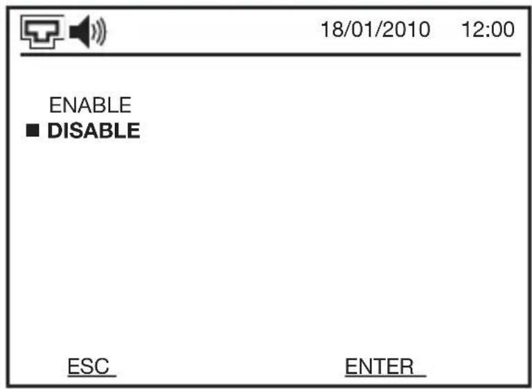
On the privacy page, use the ▲ and ▼ keys to select DISABLE, then confirm the selection with ENTER.
Call transfer
When you are not at home, or not able to answer any calls, you can activate the Call transfer function. In this way, any incoming calls can be directed as you prefer to:
outside intercom call.
waiting time.
When the call transfer function is active, the 📋 icon is lit up and the red LED of the key flashes.
USER INSTRUCTIONS
Enabling a call transfer
To enable the call transfer function, proceed as follows:

On the main menu page, use the ▲ and ▼ keys to select CALL TRANSFER, then confirm the selection with ENTER.

On the call transfer page, use the ▲ and ▼ keys to select the required option, then confirm the selection with ENTER.
If you have chosen VIDEO MAIL or SWITCHBOARD, the procedure is now complete. With TO ANOTHER AU, you will see a list of apartment numbers to which you can transfer the call.
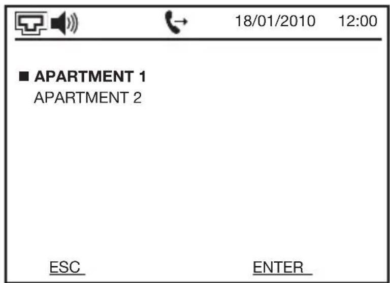
Use the ▲ and ▼ keys to select the required apartment number, then confirm the selection with ENTER. The name of the apartment corresponds with the one configured in the Customisation items menu, which can be accessed from the SETTINGS menu.
USER INSTRUCTIONS
Disabling a call transfer
To disable the call transfer function, proceed as follows:

On the main menu page, use the ▲ and ▼ keys to select CALL TRANSFER, then confirm the selection with ENTER.

On the call transfer page, use the ▲ and ▼ keys to select DISABLE, then confirm the selection with ENTER.
When the call transfer function is disabled, the 📞 icon will switch off and the red LED of the 🔔 key will stop flashing.
Baby monitoring function
The baby monitoring function allows you to check what is happening in the room where another apartment unit is installed. Only the devices of the same apartment can be activated.
With this function, a 1-way communication is established. The call position cannot hear anything, and cannot receive calls.
Activating the remote baby monitoring function
To activate the remote baby monitoring function, proceed as follows:
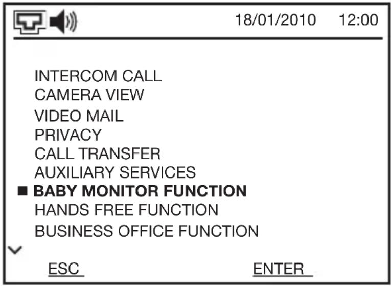
On the main menu page, use the ▲ and ▼ keys to select BABY MONITOR FUNCTION, then confirm the selection with ENTER.

On the page that appears, use the ▲ and ▼ keys to select the room in which you want to listen, then confirm the selection with CALL.
NB: the general indications ROOM ... can be customised by the user to make them easier to recognise. For further information, refer to Customising the menu items.
USER INSTRUCTIONS
“CALL” will be replaced by “END” to confirm the actual connection. On the screen of the video entryphone called, you will see the words “MONITORING ACTIVATED BY: I.P. x” (where x indicates the number of the video entryphone that is monitoring), and the green LED of the inside calling position will light up.
Deactivating the remote baby monitoring function
The remote monitoring function will remain enabled until it is deliberately deactivated (there is no time-out).
To deactivate the function, press END on the video entryphone that made the call, or on the one called.
Hands free function
This function automatically activates the microphone and loudspeaker of the video entryphone speakerphone 3 seconds after receiving the call. To answer, the user does not need to press the 📋 key (which is only used to end the communication).
When the Hands free function is active, the 🔔 icon is lit up.
The Hands free function cannot be enabled on more than one video entryphone at a time: if it is activated on a new video entryphone, it will be automatically disabled on the previously activated apartment unit.
Enabling or disabling the hands free function
To enable the Hands free function, proceed as follows:

On the main menu page, use the ▲ and ▼ keys to select the hands free function, then confirm the selection with ENTER.
USER INSTRUCTIONS

On the hands free function page, use the ▲ and ▼ keys to select ENABLE, then confirm the selection with ENTER
To disable the Hands free function, follow the same steps but select DISABLE, then confirm the selection with ENTER.
Business office function
The Business office function allows you to automatically activate the opening of the electro-lock on the front door unit when a call is received.
This function is only active in the range time specified; at other times, operation is normal.
You can set up to 2 time intervals per day, for example to deactivate the function during the lunch break. The times can be set with a 1-minute interval.

ATTENTION: the Business office function uses the internal video entryphone clock. If this is not set at the right time, the operation will not correspond with the intended time intervals.
When this function is activated on the video entryphone, it is automatically enabled on all the other positions in the office as well.
The enabling of the Business office function disables the Hands free function, if the latter was previously active.
When the Business office function is active, the icon is lit up.
Setting the range time
To set one or both range time, proceed as follows:

On the main menu page, use the ▲ and ▼ keys to select BUSINESS OFFICE FUNCTION, then confirm the selection with ENTER.

On the page that appears, use the ▲ and ▼ keys to select the range time you want to set, then confirm the selection with ENTER. It is not necessary to set all the range time. If the start and end times coincide, that range time will be automatically disabled.

The start times (on the left) and end times (on the right) are shown in the time format: minutes. The modifiable data item will flash. To modify a data item, use the ▲ and ▼ keys; to accept the data item entered, or to confirm the one shown and move on to the next one, press ENTER.
USER INSTRUCTIONS
If the end time is earlier than the start time, or if the two range time overlap, the video entryphone will annul the setting and the screen will visualise the message “INCOR-RECT RANGE TIME”, followed by a beep.

ATTENTION: the range time is only memorised after pressing ENTER to confirm the minutes of the end time.
To go back and modify a data item already entered, press ESC. By pressing ESC several times, you can exit without modifying the start and end times of the range time.
Enabling the business office function
To enable the Business office function, proceed as follows:
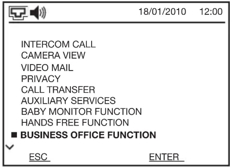
On the main menu page, use the ▲ and ▼ keys to select BUSINESS OFFICE FUNCTION, then confirm the selection with ENTER.

On the page that appears, use the ▲ and ▼ keys to select ENABLE, then confirm the selection with ENTER.
USER INSTRUCTIONS

ATTENTION: when the Business office function is enabled, all the range time are enabled.
Disabling the business office function
To disable the Business office function, proceed as follows:

On the main menu page, use the ▲ and ▼ keys to select BUSINESS OFFICE FUNCTION, then confirm the selection with ENTER.

On the page that appears, use the ▲ and ▼ keys to select DISABLE, then confirm the selection with ENTER.

ATTENTION: the disabling does not delete the range time memorised; their operation will be reactivated when the business office function is again enabled.
Auxiliary services
Via the video entryphone, you can command the outputs of the relay units (GW 18 381). From these outputs it is possible to activate auxiliary devices such as lights, secondary electro-locks, and electric gates.
Activating an auxiliary service (relay)
There are two ways to activate an auxiliary service with the relay unit (GW 18 381): using the menu or the up/down arrows button keys. To configure the latter method, refer to the paragraph Secondary function configuration of the up/down arrow navigation button keys.
Using the up/down arrow button keys, simply press the button key (with the screen on and not in the menu) once to send the command to the relay module. A maximum of two outputs can be activated with this method.
Use the menu to carry out the following:

On the main menu page, use the ▲ and ▼ keys to select AUXILIARY SERVICES, then confirm the selection with ENTER.

On the page that appears, use the ▲ and ▼ keys to select the relay units (REMOTE RELAY INTERFACE...) that manages the service you want to activate, then confirm the selection with ENTER. The menu is only visible if there are relay units in the system.
USER INSTRUCTIONS
The maximum number of relay units that can be installed in a system is 4, giving a total of 16 relay outputs and 4 outputs for electro-locks. The number of auxiliary services shown in the menu mirrors the total number of relay unit outputs present in the system.
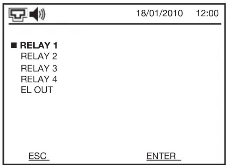
On the relay units page that opens, use the ▲ and ▼ keys to select the service (relay) you want to activate, then confirm the selection with ENTER.
After the command has been entered, you will see the message “COMMAND ENTERED” on the screen.
NB: the general indications RELAY ..., EL OUT can be customised by the user to make them easier to recognise. For further information, refer to Customising the menu items.
USER INSTRUCTIONS
Maintenance
The device does not require any maintenance.
If you wish to clean it, use a dry cloth. Do not use abrasive products, and avoid scratching the glass of the screen.
INSTALLATION INSTRUCTIONS

ATTENTION: the device must only be installed by qualified personnel, observing the current regulations and the guidelines for video entryphone installations.
Correct position
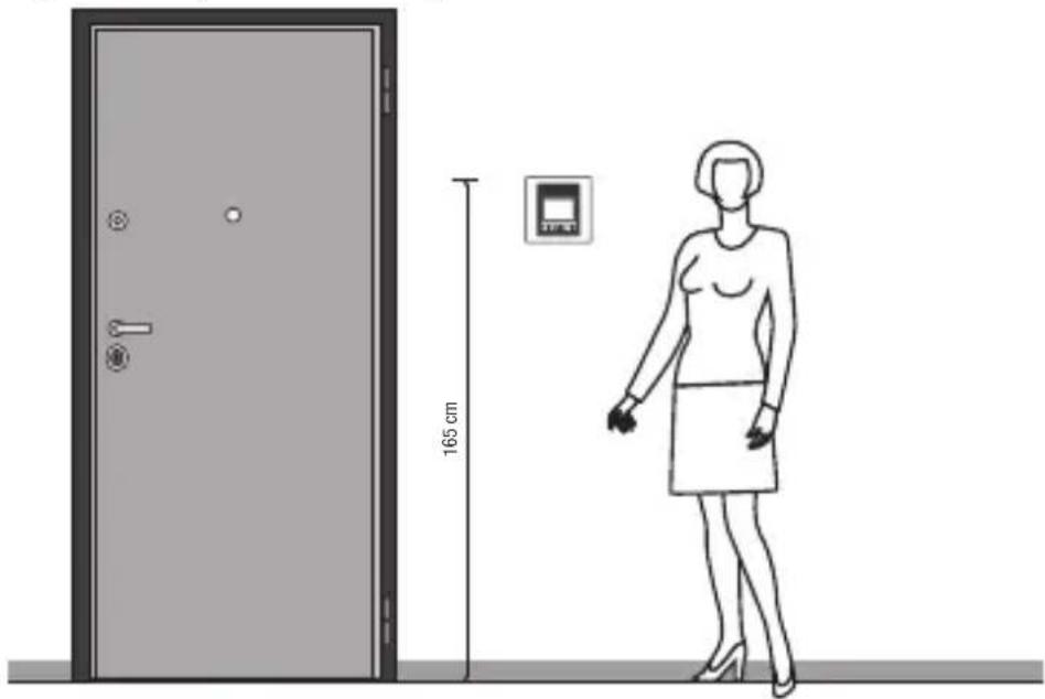
The video entryphone must be positioned at a height of about 165 cm from the ground, using the flush-mounting box GW 24 237 for version GW 18 341 xx. For the wall-mounting version (GW 18 343 xx), no box is needed.
Warnings for installation
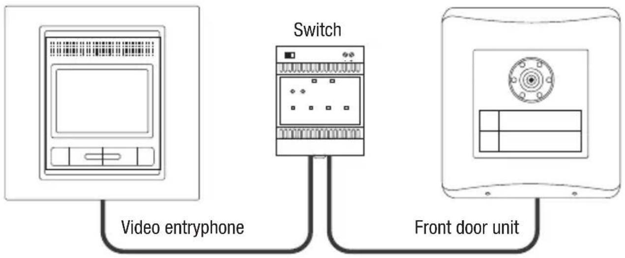
- The video entryphone must be connected directly to the PoL port of the Ethernet switch (GW 18 371), using a LAN UTP network cable, 5e or higher category (refer to Connection diagram).
- In the case of a direct connection to the front door unit (a single family building with just one video entryphone), the connection between the two devices must be made with a LAN UTP network cable of Category 5e or higher, of the non-direct type (refer to Connection diagram).
- The length of the LAN network cable may not exceed 100 metres.
- The video entryphone is powered via the LAN network cable (PoL - Power over LAN).
- The length of the landing call cable (optional) must not exceed 50 m, with a section of 1 mm^2 .
- The length of the electric load cable connected to the relay output (optional) must not exceed 50 m, with a section of 1 mm ^2 .
- For the relay output, do not exceed 24V AC/DC, with a 3A current.
INSTALLATION INSTRUCTIONS
Connection diagram
Switch connection
The diagram shown below uses a direct type LAN network cable. For the direct cable pinout, refer to Electric connections.
flowchart
graph LR
    A["Video entryphone"] --> B["Switch"]
    B --> C["Front door unit"]
Direct connection to the front door unit
The diagram shown below is only used in the case of a single-family system with a single video entryphone with one front door unit.
An indirect LAN network cable is used for the connection. For the indirect cable pinout, refer to Electric connections.

INSTALLATION INSTRUCTIONS
Connectors position

Electric connections

ATTENTION: before making the electric connections, make sure all the equipment and cables are not powered.
- Connect any external push-button (door call) to terminals 1 and 2 of the terminal block.
- Connect any external load (max. 24V - 3A) to the relay output (terminals 2 and 3 of the terminal block).
- Connect the LAN network cable to the RJ45 port and wait about 1 minute until the video entryphone has completed the initialisation operations.
INSTALLATION INSTRUCTIONS
Direct RJ45 - RJ45 LAN network cable wiring diagram
Suitable for all wiring where Ethernet Switches (GW 18 371) are used.


| conductor colour pin signal conductor colour | |||
| white orange 1 Tx+ white orange | |||
| orange 2 Tx- orange | |||
| white green 3 Rx- white green | |||
| blue 4 GND blue | |||
| white blue 5 GND white blue | |||
| green 6 | Rx+ | green | |
| white brown | 7 | +V dc | white brown |
| brown | 8 | +V dc | brown |
NB: it is recommended to use a UTP LAN network cable cat.5e (or higher) that is specific for outside installation (e.g. GW 38 195).
INSTALLATION INSTRUCTIONS
Indirect RJ45 - RJ45 LAN network cable wiring diagram
Only suitable for directly connecting the outside call position with a single apartment unit (single family video entryphone kit).


| conductor colour pin conductor colour | ||
| white orange 1 white | green | |
| orange 2 green | ||
| white green 3 white | orange | |
| blue 4 blue | ||
| white blue 5 white | blue | |
| green 6 orange | ||
| white brown 7 white | brown | |
| brown 8 brown |
NB: t is recommended to use a UTP LAN network cable cat.5e (or higher), that is specific for outside installation (e.g. GW 38 195).
INSTALLATION INSTRUCTIONS
Fixing and completion
Flush-mounting video entryphone

natural_image
Diagram of an open electronic device showing internal components and a close-up view of the screen (no text or symbols present)- Fix the video entryphone in the flush-mounting box GW24237 (not supplied), using the screws supplied.
- Complete the video entryphone with the cover plate supplied.
Wall-mounting video entryphone

natural_image
Technical line drawing showing three views of a device panel with mounting holes and a central control panel (no text or symbols)-
Fix the wall-mounting bracket using the wall plugs supplied. Alternatively, it can be screwed above a flush-mounting boxes with 3 modules (horizontal or vertical), or round/square flush-mounting boxes with 2 modules (60 mm centre distance). The bracket has its own level indicator so you can check the levelling is correct.
-
Connect the LAN network cable and the terminal block (if used).
- Fix the video entryphone on the bracket.
- Complete the video entryphone with the cover plate supplied.
Configuration
The configuration operations must be carried out after all the devices have been connected to the system, and after the system has been powered.
After powering the system, wait one minute until the video entryphone has completed the initialisation operations.
During the configuration, there must be no calls in progress.
Logic connection between front door unit push-button and video entryphone
The following procedure only applies for systems with no more than 2 front door units (one primary and one secondary, but without an electronic index), 34 apartments (maximum 4 apartment units for each apartment), 1 relay unit (GW 18 381), and 1 camera interface (GW 18 376).
If the system exceeds these limits (for instance with more front door units, more apartments, camera interfaces or more relay units), the configuration must be carried out via a PC and system configuration software.
NB: if the configuration has not been carried out on the bench (before installing the single devices as described), but directly in the system, the presence of 2 people may be necessary so it is easier to make the logic connections between push-buttons of front door units and the apartment units.

ATTENTION: if 2 front door units are installed in the system, configure the secondary one first, then the primary one.

ATTENTION: the camera interface (GW18 376) and relay units (GW 18 381) must be connected and operating before carrying out the configuration operations, so they can be automatically inserted in the video entryphone menu.
To logically connect a video entryphone to the push-button of the front door unit, proceed as follows:
- With the audio/video module of the front door unit switched off, put the module into Programming mode by turning switch 1 of DIP switch 2 to ON.
- Switch on the audio/video module.
- Wait until the audio/video module emits 1 beep followed by 3 beeps, indicating the enabling of the learning procedure for the devices connected to it.
- Set the learning mode of the video entryphone with speakerphone in the following way:
INSTALLATION INSTRUCTIONS

Access the menu by pressing the MENU key.
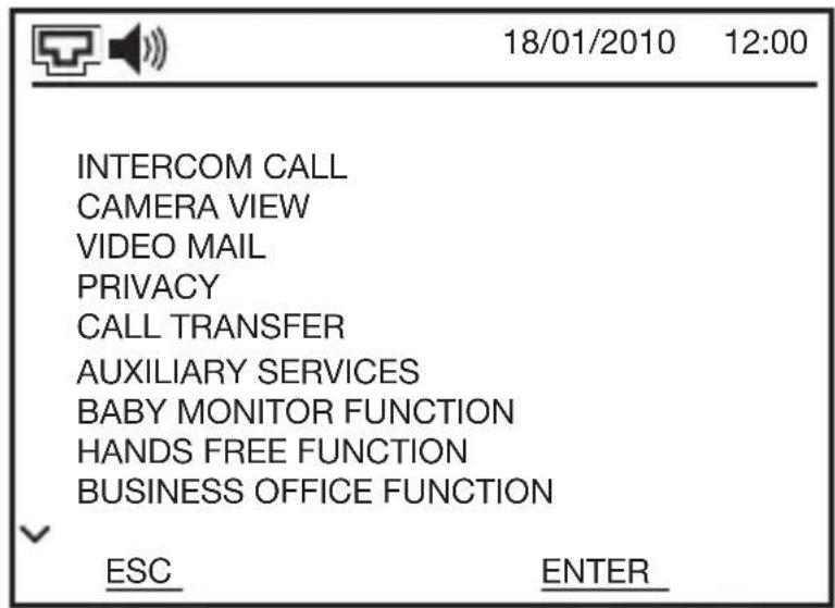
On the main menu page, use the ▲ and ▼ keys to select SETTINGS, then confirm the selection with ENTER.

On the settings page, use the ▲ and ▼ keys to select LEARNING MODE, then confirm the selection with ENTER.
INSTALLATION INSTRUCTIONS

The video entryphone will go into standby until it receives a call from the front door unit (FDU).
-
Wait until the outside call position emits a single beep, then press the call key that you want to associate with the video entryphone. Every old association with other apartment units will be deleted. NB: if the front door unit does not receive the confirmation, re-enable the learning mode in the apartment unit.
-
Press the 🔒 key on the video entryphone. The video entryphone beeps to confirm the success of the logic connection, and you will see the word “CONFIGURED” on the screen.
The green LED corresponding to the assigned intercom number (the internal intercom number of the apartment) will light up.
- If there are other video entryphones in the apartment, that need to be logically connected to the same push-button of the front door unit, repeat steps 4-6 for each of them.
When associating other devices with the same push-button of the front door unit, they automatically adopt the first number available (2, 3 or 4) for the internal intercom. NB: each push-button of the front door unit can manage up to 4 devices per apartment units (the upper limit for an apartment).
Important: if additional apartment units are added to a push-button at a later moment, it will also be necessary to reconfigure the devices of that apartment that have already been programmed, respecting the previous programming order.
-
Repeat the procedure from point 4 in order to connect the next push-button of the front door unit to the corresponding video entryphone.
-
After configuring all the necessary push-buttons of the front door unit (if the total number of push-buttons is greater than that of the apartments, you do not need to configure the extra ones), switch off the audio/video module of the front door unit, take it out of the Programming mode by turning switch 1 of DIP switch 2 to OFF, then switch the device back on again.
-
If the system has another outside call position, repeat the entire procedure (from point 1) with that position as well.
-
At the end of the procedure, switch all the apartment units off then back on again.
INSTALLATION INSTRUCTIONS
Setting the functions and parameters
Language
To set the language of the menus and messages, proceed as follows:
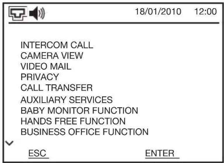
On the main menu page, use the ▲ and ▼ keys to select SETTINGS, then confirm the selection with ENTER.
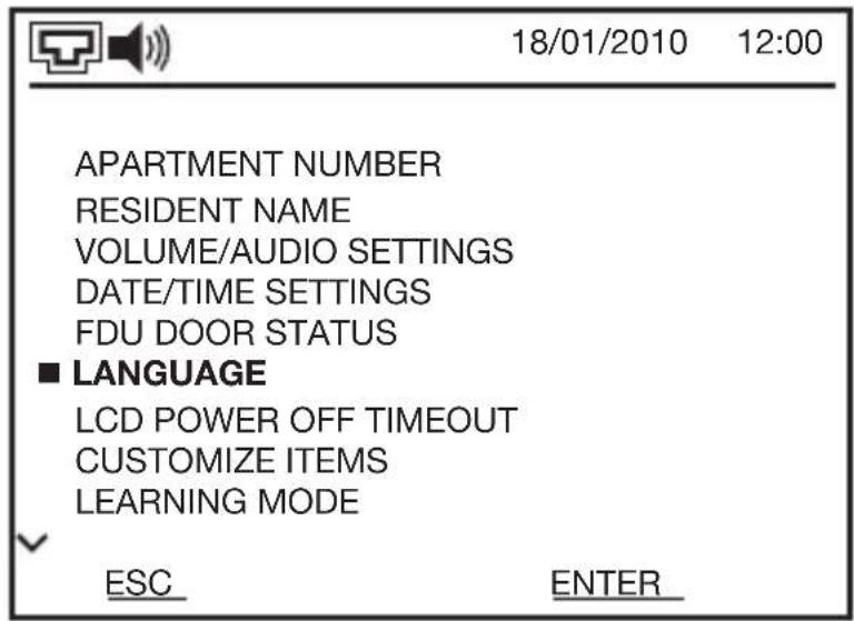
On the settings page, use the ▲ and ▼ keys to select LANGUAGE, then confirm the selection with ENTER.
On the page that opens, use the ^ and ▼ keys to select the required language, then confirm the selection with ENTER.
INSTALLATION INSTRUCTIONS
FDU door status
Certain electro-locks are equipped with an output that signals their status (closed or open). This output can be connected to the relevant input of the outside video entryphone position.
If you make this connection and the FDU DOOR STATUS function is activated, the flashing 🔊 icon will appear on the video entryphone with speakerphone when the door remains open for more than 5 minutes. In addition, you can also enable the sound signal, that lasts about 1 minute.
To activate or deactivate the function:

On the main menu page, use the ▲ and ▼ keys to select SETTINGS, then confirm the selection with ENTER.

On the settings page, use the ▲ and ▼ keys to select FDU DOOR STATUS, then confirm the selection with ENTER.
INSTALLATION INSTRUCTIONS

On the page that appears, use the ▲ and ▼ keys to select ENABLE or DISABLE, then confirm the selection with ENTER. NB: when you disable this function, you also disable any sound signal associated with it.
To enable or disable the associated warning sound, go back to the same page and select WARNING SOUND. On the page that opens, select ENABLE or DISABLE, then confirm the selection with ENTER. The warning sound emitted is a beep.
Switching off the screen
The video entryphone screen switches off automatically if it is left unused for a certain period of time; this avoids any damage, and reduces energy consumption. This time range can be programmed as follows:

On the main menu page, use the ▲ and ▼ keys to select SETTINGS, then confirm the selection with ENTER.
INSTALLATION INSTRUCTIONS

On the settings page, use the ▲ and ▼ keys to select LCD POWER OFF TIMEOUT, then confirm the selection with ENTER.

On the page that appears, use the ⬆ and ⬇ keys to select the required idle time before the screen switches off. The possible choices are AFTER 30 SECS., AFTER 1 MIN. and AFTER 3 MINS. Confirm the selection with ENTER.
Inside/outside intercom
You can configure the video entryphone to enable the 2-way audio intercommunicating communication (full duplex) with other apartment units (video entryphones, wall-mounting/flush-mounting entryphones) of the system - both those belonging to the same apartment and those belonging to other apartments.
The intercom inside function is automatically created during the configuration, when the logic connection is made between the push-button of the front door unit and apartment units of a single apartment.
The intercom outside function, on the other hand, has to be purposely configured. You can create up to 4 outside intercom connections. The programming of any apartment unit will be automatically memorised in the other video entryphones.
INSTALLATION INSTRUCTIONS

ATTENTION: the outside intercom call function that is created is 1-way (the communication established is, however, 2-way).

ATTENTION: even if the intercommunication function is enabled between two video entryphones, the communication will always be audio only, because the video entryphones are not equipped with telecameras.
To configure intercom call-outside, proceed as follows:
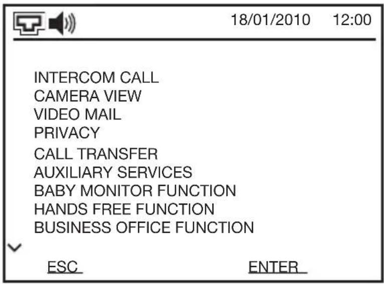
On the main menu page, use the ▲ and ▼ keys to select SETTINGS, then confirm the selection with ENTER.
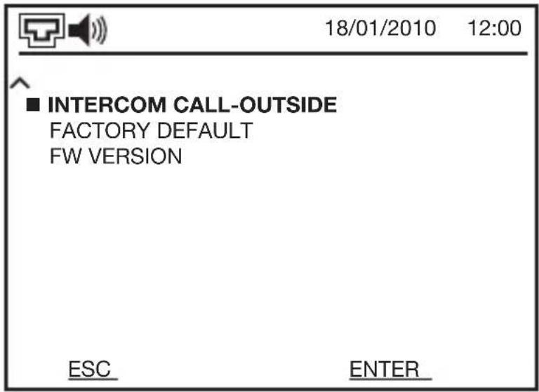
On the settings page, use the ▲ and ▼ keys to select INTERCOM CALL-OUTSIDE, then confirm the selection with ENTER.
INSTALLATION INSTRUCTIONS

On the intercom call-outside page, use the ▲ and ▼ keys to select SET CALL NR.1, then confirm the selection with ENTER.

On the page that opens, set the apartment number with which you want to establish the outside intercom function. The modifiable figure will flash. To modify the value, use the ▲ and ▼ keys. Use ENTER to confirm the figure and move on to the next one, or BACK to return to the previous figure.
The procedure for knowing the apartment number of another video entryphone is explained in Identification data below; the procedures for the other front door units are explained in the respective Instruction Manuals or the Technical System Manual.
If you wish to establish additional outside intercom calls-outside, set the other apartment numbers in SET CALL NR.2, SET CALL NR.3 and SET CALL NR.4. You can modify the apartment number with words, so it is easier to identify (for example, Rossi Family). The procedure is explained in Customising the menu items.
INSTALLATION INSTRUCTIONS
After configuring the calls, enable the intercom call-outside by selecting ENABLE on the page of the intercom call-outside, then confirm the selection with ENTER. By selecting DISABLE and confirming with ENTER, you will disable the incoming intercom call-outside.
Relay management

ATTENTION: without using the PC and configuration software, it is still possible to directly configure a single relay unit - from DIN rail (GW 18 381) from the video entryphone.
The operation of the local relay (inside the video entryphone) and the electro-lock command, along with the 4 relays of the relay unit - from DIN rail (GW 18 381) that may be present in the system, can be customised in the following way:

On the main menu page, use the ▲ and ▼ keys to select AUXILIARY SERVICES, then confirm the selection with ENTER.

On the page that appears, use the ▲ and ▼ keys to select the relay to be configured, then confirm the selection with ENTER.
REMOTE RELAY INTERFACE... are the relay units that may be present in the system, with their relays.
INSTALLATION INSTRUCTIONS

In the case of LOCAL RELAY, the screen will visualise the page on which you can select the functions and parameters to be customised.
Use the ▲ and ▼ keys to select the item to be modified, then confirm with ENTER.
The ▲ and ▼ keys are also used to modify the value of the individual parameters.
The possible options are:
» DOOR LOCK: when a call is received from the door lock (local push-button), all the apartment units ring. With the Ⓞ→ push-button of any apartment units of the apartment, the user can activate all the local relays and interrupt the ring.
» DISABLE: to disable the local relay.
240 seconds (4 minutes).
Secondary function configuration of the up/down arrow navigation button keys
The two up/down arrow button keys are used not only to navigate the menu but also to activate the relay outputs of the relay unit (GW 18 381) or activate the lock of the secondary front door unit. Proceed as follows to configure these button keys:
- To select the lock of the secondary front door unit
a. access the "CAMERA VIEW" menu
b. use the up/down arrows to select the desired secondary position
c. press and hold the up or down arrow button key until the video entryphone emits a confirmation beep.
- To select a relay unit output:
a. access the "AUXILIARY SERVICES" menu
b. use the up/down arrows to select the desired relay module
c. use the up/down arrows to select the desired activation
d. press and hold the up or down arrow button key until the video entryphone emits a confirmation beep.
The video entryphone displays an orange line in the lower part of the display (in correspondence of the button key) to indicate that the second function has been selected.
INSTALLATION INSTRUCTIONS
A new configuration can be selected for the button key by repeating the instructions indicated above. To cancel the selection, hold down the button key for at least 5 seconds with the screen on and not in the menu.
Other parameters to be configured
To configure the other parameters (date, time, volume/audio settings, etc.) or functions, refer to Standard configuration, Video mail, Hands free function and Business office function in User Instructions.
Customising the menu items
You can modify the general factory name that identifies certain functions or devices. In this way, using a name that has a meaning for you, they (or the associated function) will be easier to recognise.
How to modify a name
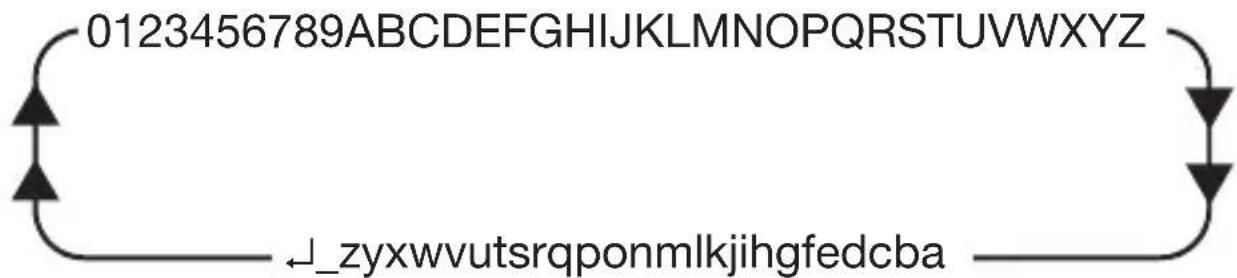
To modify a name, you can use the capital letters (A-Z), small letters (a-z), numbers (0-9), space (_) and “new line” character ( ), used to end the insertion of the text. The names can contain up to 15 characters.
The available characters are selected with the ▲ and ▼ keys in the following cyclical sequence:
flowchart
graph TD
    A["0123456789"] --> B["↓_zyxwvutsrqponmlkjihgfedcba"]
    B --> C["→"]
    C --> D["↓"]
    D --> E["→"]
The modification procedure is as follows:

ge it, if necessary (by keeping the key pressed, you can scroll quickly through the characters).
memorised.
re without modifying the name stored.
INSTALLATION INSTRUCTIONS
Customising a name
To customise a name, proceed as follows:

On the main menu page, use the ▲ and ▼ keys to select SETTINGS, then confirm the selection with ENTER.

On the settings page, use the ▲ and ▼ keys to select CUSTOMIZE ITEMS, then confirm the selection with ENTER.
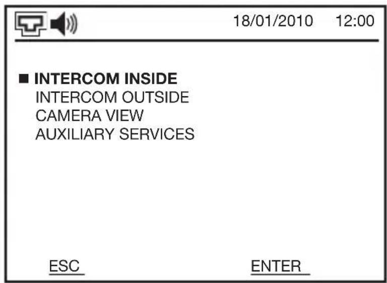
The screen will visualise the page on which you can customise the menu items. From here, you can use the ▲ and ▼ keys to select (and confirm, using ENTER) the following specific pages:
INSTALLATION INSTRUCTIONS
the apartment, if there are any.
(max. 4) equal to the intercommunicating connections that have been configured. If no outside intercommunicating connections have been configured, this page will be empty.
ras, and the camera interfaces of the video entryphone system.
one inside the video entryphone) and the relay units.
On the specific page, use the ▲ and ▼ keys to select the name you want to modify, then confirm the selection with ENTER. Make the modification as explained in How to modify a name.
INSTALLATION INSTRUCTIONS
The resident's name
From the video entryphone you can insert or modify the name (name 1 and name 2) of the person living in the apartment. These names are visualised in the Call module with electronic index for front door unit (GW 18 322), if this is present in the system.
The two names are stored directly in the electronic index, so if an apartment has more than one video entryphone you only need to apply this procedure to one of them and the two names will appear on all the others as well.
If the system includes several electronic indexes, they will all be updated simultaneously.
To insert or modify a name, proceed as follows:

On the main menu page, use the ▲ and ▼ keys to select SETTINGS, then confirm the selection with ENTER.

On the settings page, use the ▲ and ▼ keys to select RESIDENT NAME, then confirm the selection with ENTER.
INSTALLATION INSTRUCTIONS
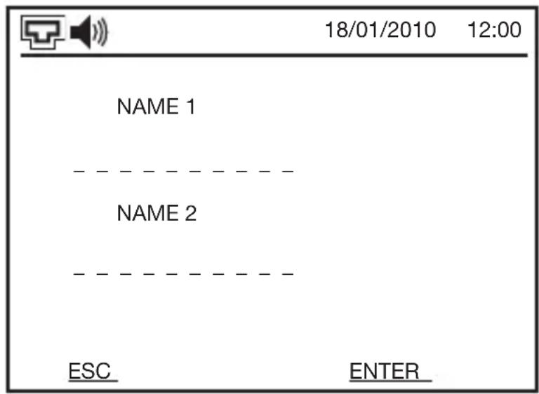
On the page that opens, you can insert two names to identify the person living in the apartment. NAME 1 and NAME 2 together can contain up to 20 characters. After you have inserted NAME 1, the video entryphone will automatically update the remaining number of characters for NAME 2.
To insert or modify the name, refer to the procedure explained in How to modify a name.
NB: the video entryphone automatically updates the names in all the call modules with electronic index (GW 18 322) in the system.
INSTALLATION INSTRUCTIONS
Identification data
To discover the apartment number assigned to the video entryphone, and the fw version it uses, proceed as follows:

On the main menu page, use the ▲ and ▼ keys to select SETTINGS, then confirm the selection with ENTER.

On the settings page, use the ▲ and ▼ keys to select the required item (APARTMENT NUMBER or FW VERSION), then confirm the selection with ENTER.
On the page that opens, you will see either the apartment number (a 9-figure number) or the fw version of the video entryphone (a number with the format x.x.x.x).
INSTALLATION INSTRUCTIONS
Resetting the factory configuration
If necessary, you can bring the video entryphone back to its factory configuration, setting the following parameter values:
| Video mail enabled |
| Privacy disabled |
| Call transfer disabled |
| Hands free function disabled |
| Business office function disabled |
| Speaker volume 50% |
| Melodies volume 50% |
| Date format DD/MM/YY |
| Time format 24H |
| FDU door status disabled |
| Front door unit alarm disabled |
| Language ITA |
| Lcd power off timeout 30 SECS. |
| Intercom call-outside Numbers eliminated |
With this reset, you will lose any keying in text you have made, along with the logic connections (inside intercom, outside intercom, with the outside call positions) configured.

On the main menu page, use the ▲ and ▼ keys to select SETTINGS, then confirm the selection with ENTER.
INSTALLATION INSTRUCTIONS
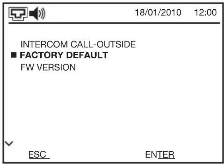
On the settings page, use the ▲ and ▼ keys to select FACTORY DEFAULT, then confirm the selection with ENTER.
On the page that opens (showing the item RESTORE), keep the ▼▼ key pressed for 3 seconds. The words DELETE CONFIGURATION will appear. Confirm the operation with ENTER. The video entryphone will emit a long, 2-second beep while it is resetting the factory configuration.

ATTENTION! The resetting of the factory configuration is an irreversible operation; you will lose all the customisations you have made.
Resetting the video entryphone
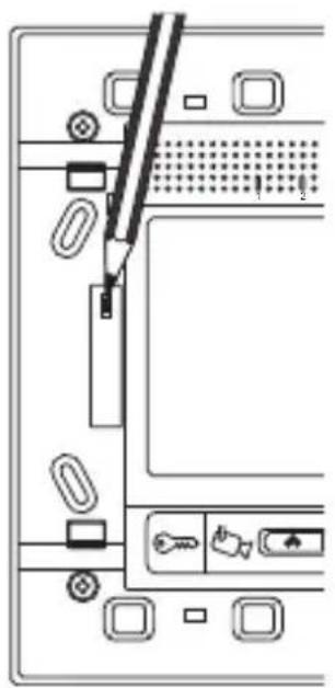
In the unlikely case that the video entryphone becomes blocked, or an anomaly arises during operation, you can restart the device without disconnecting the power supply.
natural_image
Diagram of a computer monitor front panel with indicator lights and ports (no text or symbols)To do this, remove the plate that protects the video entryphone, then press the flush-mounted button on the left with the aid of a pencil or pen (as shown in the figure).
After resetting, wait a minute to allow the video entryphone to complete the initialisation operations.
Check the video entryphone is working correctly, then replace its plate.
TECHNICAL DATA
| Communication Ethernet LAN network, max. speed 100 Mbps | |
| Application level protocol: RTSP | |
| Transport level protocol: UDP multicast | |
| Internetworking level protocol: IPv4 | |
| Audio/video coding MPEG | |
| Power supply Via LAN network cable (PoL - Power over LAN), 14.4V | |
| DC SELV | |
| Current absorption 200 mA in stand-by | 240 mA during the communication |
| max. 250 mA | |
| LAN network cable Cat 5e or higher | |
| Inputs 1 auxiliary contact for potential-free local push-button | |
| Outputs | 1 single-pole output with relay - NO (24V - 3A) - can be timed |
| Control elements 6 front push-buttons | |
| Display elements 1 LCD TFT colour display, backlit, diagonal 3.5", 320 x | |
| 240 pixel resolution | |
| 1 red LED for Privacy function | |
| 1 green LED for Answer function | |
| 4 green/red LEDs for Intercom function | |
| Audio elements | Microphone: sensitivity -40dB; |
| Loudspeaker: 0.5W - answer in a frequency of 600 - 4 kHz | |
| Warning elements Ringer with 10 ringtones | |
| Adjustable volume | |
| Connection to a video entryphone system | RJ45 port |
| Electric connections Extractable screw terminal | |
| Maximum cable section 1.5 mm2 | |
| Usage environment Dry inside places | |
| Operating temperature 0 ÷ +45°C | |
| Storage temperature -15 ÷ +70°C | |
| Relative humidity Max. 93% (non condensative) | |
| Degree of protection IP20 | |
| Dimensions (L x H x D) | 150x158x43 mm (including the plate supplied) |
| Weight | 0.33 kg |
| Reference Standards | Electromagnetic compatibility: |
| 2004/108/EC, EN 61000-6-1, EN 61000-6-3 | |
ESPAÑOL
ÍNDICE 145
natural_image
Icon of a stylized document with a speech bubble, no text or symbols presentFigura 1
natural_image
Circular icon with a stylized human figure inside an open door, set against a dark background (no text or symbols)Figura 2
natural_image
Technical line drawing of an open electronic device showing internal components and a separate panel (no text or symbols)natural_image
Technical line drawing showing three views of a device panel with mounting holes and a central control panel (no text or symbols)natural_image
Diagram of a computer monitor front panel with indicator lights and ports (no text or symbols)Visualizar as imagens de todas as telecâmeras 240
Excluir as chamadas 248
Aceitar as chamadas 249
Transferir chamada 250
natural_image
Icon of a stylized document with sound waves, no text or symbols presentFigura 1
Chamada externa de módulo áudio

natural_image
Simple icon of a person inside a door, enclosed in a circular frame (no text or symbols)Visualizar as imagens de todas as telecâmeras
natural_image
Diagram of an open electrical enclosure with internal components and a separate view showing internal wiring (no text or labels)natural_image
Technical line drawing of three electronic panel components: a front panel, a screen with buttons, and a square frame (no text or symbols)natural_image
Diagram of a computer monitor front panel with indicator lights and ports (no text or symbols)


- USER INSTRUCTIONS 82
- INDEX
- Privacy 104
- Call transfer 106
- Baby monitoring function 109
- Hands free function 110
- Business office function 111
- Auxiliary services
- Maintenance
- INSTALLATION INSTRUCTIONS 118
- TECHNICAL DATA 143
- GENERAL WARNINGS
- Pack Contents
- Briefly
- GENERAL DESCRIPTION
- Control positions and functions
- KEY
- Information regarding the screen
- USER INSTRUCTIONS
- Answering a call
- Making adjustments during the call
- Call priorities
- Menu
- Stored parameter
- Standard configuration
- Setting the date and time
- Loudspeaker volume
- Calls: setting the volume and choosing the ringtone
- Feedback buttons beep
- Intercom call
- Making an intercom call
- LED signalling
- Terminating the intercom call
- Camera view
- Visualising the images from all the telecameras
- Visualising the images from a specific telecamera
- Listening during camera view
- Opening the door
- Video mail
- Enabling or disabling the video mail
- Recording a video message
- Viewing a video message
- Deleting a video message
- Deleting all the video messages
- Privacy
- Excluding a call
- Accepting calls
- Call transfer
- Enabling a call transfer
- Disabling a call transfer
- Baby monitoring function
- Activating the remote baby monitoring function
- Deactivating the remote baby monitoring function
- Hands free function
- Enabling or disabling the hands free function
- Business office function
- Setting the range time
- Enabling the business office function
- Disabling the business office function
- Activating an auxiliary service (relay)
- INSTALLATION INSTRUCTIONS
- Correct position
- Warnings for installation
- Connection diagram
- Switch connection
- Direct connection to the front door unit
- Connectors position
- Electric connections
- Direct RJ45 - RJ45 LAN network cable wiring diagram
- Indirect RJ45 - RJ45 LAN network cable wiring diagram
- Fixing and completion
- Flush-mounting video entryphone
- Wall-mounting video entryphone
- Configuration
- Logic connection between front door unit push-button and video entryphone
- Setting the functions and parameters
- Language
- FDU door status
- Switching off the screen
- Inside/outside intercom
- Relay management
- Secondary function configuration of the up/down arrow navigation button keys
- Other parameters to be configured
- Customising the menu items
- How to modify a name
- Customising a name
- The resident's name
- Identification data
- Resetting the factory configuration
- Resetting the video entryphone
- TECHNICAL DATA
- ESPAÑOL
- ÍNDICE 145
- Transferir chamada 250
- Visualizar as imagens de todas as telecâmeras
Brand : Gewiss
Model : GW18343VT
Category : Intercom