ERM-871 - Access Control System EverFocus - Free user manual and instructions
Find the device manual for free ERM-871 EverFocus in PDF.


| Product Type | 125 kHz Proximity Reader (Mullion form factor) |
| Brand | EverFocus |
| Model | ERM-871 |
| Frequency | 125 kHz |
| Read Range | 5-10 cm (2-3.9 in) |
| Read Time | 200 ms |
| Output Formats | Wiegand 26 or Special RS-232 (9600 bps) |
| Power Supply | 6.5-18 V DC, 150 mA max |
| LED Indicators | Red (Power), Green (Card Present), Yellow (Outer Source) |
| Audio Buzzer | Built-in, 2 kHz |
| Weather Resistance | Weather resistant, suitable for indoor/outdoor |
| Operating Temperature | -10°C to 60°C (14°F to 140°F) |
| Dimensions (H x W x D) | 5.52 x 1.58 x 0.95 in (14.0 x 4.0 x 2.4 cm) |
| Wire Pigtail Length | 18 in (45.7 cm) |
| Maximum Cable Distance | Up to 500 ft (152 m) with 22 AWG, 5-conductor cable |
| Transient Protection | Up to 500W |
| Tamper Switch | Yes, Normally Closed |
| Data Bit Format | 64-bit card data |
| Mounting | Surface mount with included screws and L-type spanner |
| Compatibility | EverAccess controllers and most Wiegand 26 controllers |
Frequently Asked Questions - ERM-871 EverFocus
User questions about ERM-871 EverFocus
0 question about this device. Answer the ones you know or ask your own.
Ask a new question about this device
Download the instructions for your Access Control System in PDF format for free! Find your manual ERM-871 - EverFocus and take your electronic device back in hand. On this page are published all the documents necessary for the use of your device. ERM-871 by EverFocus.
USER MANUAL ERM-871 EverFocus
natural_image
Three black electronic devices with visible ports and buttons, shown from different angles (no text or symbols on the devices themselves)EverAccess Proximity Readers
ERR-871
ERK-871
ERM-871
EVERFOCUS ELECTRONICS CORPORATION
ERR-871
ERK-871
ERM-871
Instruction Guide
© 2004 Everfocus Electronics Corp
1801 Highland Ave Duarte CA 91010
Phone 626.844.8888 • Fax 626.844.8838
All rights reserved. No part of the contents of this manual may be reproduced or transmitted in any form or by any means without written permission of the Everfocus Electronics Corporation.
Table of Contents
CHAPTER 1
Product Overview 1
Features 1
Parts List 2
Specifications 2
CHAPTER 2
Installation 4
Wiring Connections 4
Connection to Controller 5
Basic Mounting Instructions 5
CHAPTER 3
Data Format 8
Specialized RS-232 8
Wiegand 26 8
Product Overview
EverAccess Proximity Readers, including the ERR-871, ERK-871 and ERM-871, incorporate state-of-the-art technology, reliable performance, easy-to-use features, and elegant appearance. The Readers generate a 125 kHz RF field that detects data from proximity cards. The data output format is Wiegand 26 or RS-232, which allows easy integration with most controllers, including EverAccess controllers. The Readers have 3 LED indicators which emit red, green, and yellow colors that indicate different values. The pigtail wiring on the back of the Readers is 18" long, enabling easy installation. EverAccess Proximity Readers are an ideal choice for any Access Control System.
Features
➢ 125kHz proximity technology
Wiegand 26 or Special RS232 data output format
3 LED indicators
➢ Weather resistant; suitable for indoor or outdoor use
➢ 18" Wire pigtail for easy installation
Built-in audio buzzer
200ms read time
Elegant Design
➢ Transient voltage shock protection up to 500W

Parts List
Please be careful when you unpack the box due to the electronics devices inside. Check and make sure that you have all the items below inside the original box:
➢ 1 125kHz Proximity Reader
1 User manual
➢ 2 ST4*20 self-tapping panhead screws
2 M4*20 screws
➢ 1 L-type Spanner
If an item appears to have been damaged in shipment, replace it properly in its carton and notify the shipper. If any items are missing, notify your Everfocus Electronics Corp. Sales Representative or Customer Service. The shipping carton is the safest container in which the unit may be transported. Save it for possible future use.
In addition, EverAccess recommends the following parts, to be provided by the installer:
9 Wire Splice
➢ 1 DC Power Supply, 6.5-18VDC, 150mA
▶ Up to 500 ft. Cable, 22AWG, 5 Conductor
Specifications
| Regular reader Keypad reader Mullion reader | |||
| Frequency | 125 | ||
| Data format 64 bit | |||
| Read range 5-12cm (2-4.7") 5-12cm (2-4.7") 5-10cm (2-3.9") | |||
| Read time 200 ms | |||
| Output format Wiegand 26 and Special RS232 format for EverAccess controller | |||
| Audio Built-in Buzzer, 2 kHz | |||
| Indicator | 3 LEDs:Red: PowerGreen: Card PresentYellow: Outer Source | ||
| Power supply 6.5V-18V DC, Max:150mA | |||
| Operation temperature | 14°F-0°F (-10°-60°C) | ||
| Dimension | 4.85"x3.03"x0.76"(12.3x7.7x1.9cm) | 4.85"x3.03"x0.85"(12.3x7.7x2.1cm) | 5.52"x1.58"x0.95"(14.0x4.0x2.4cm) |
| Transition distance 500 ft. | |||
| Tamper switch Yes, Normally Closed | |||
| Keypad | N/Λ | 4*4 | N/Λ |
KHz
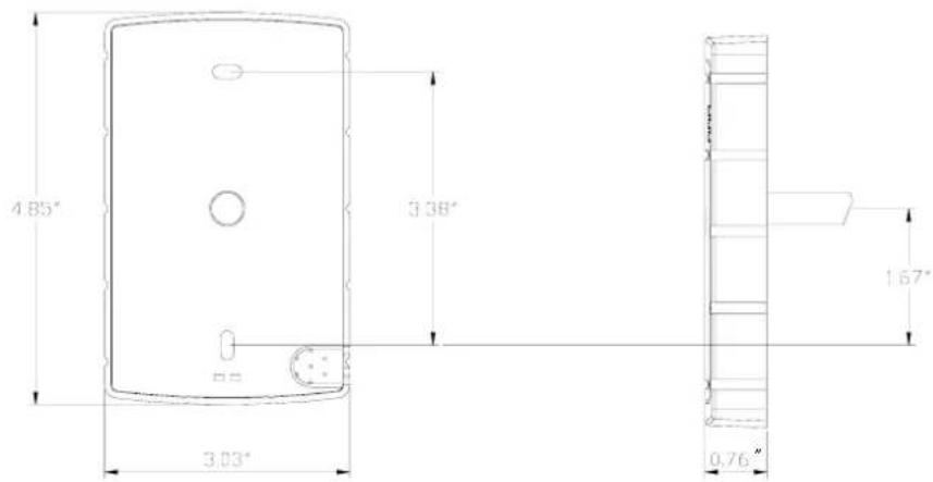
Regular Reader
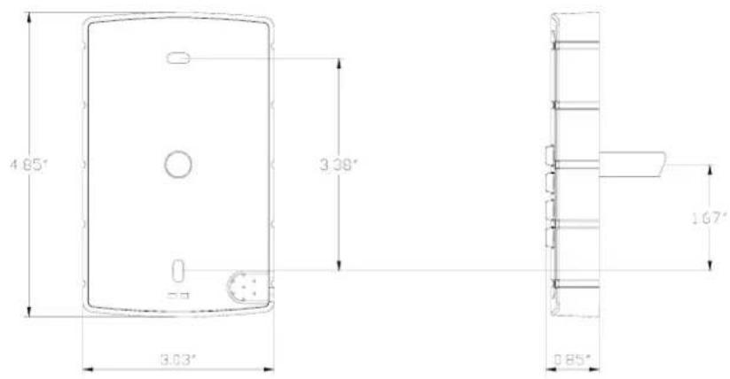
Keypad Reader
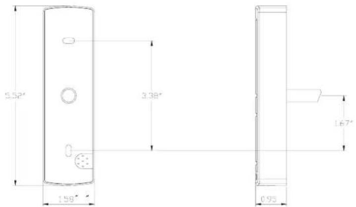
Mullion Reader
Installation
EverAccess Proximity Readers should be installed by qualified installation professionals. The installation procedures described below are recommended guidelines, but all local, state, and national electrical codes take precedence.
Please refer to the following diagram for the wiring connections and mounting instruction.
Wiring Connections
Table 2.1. Reader wires' definition
| Color Functionality | ||
| Red Power supply 6.5 ~ 18 V DC | ||
| Black | GND | |
| Green Data 0 (Wiegand) | ||
| Brown Data 1 (Wiegand) | ||
| Blue | Specialized RS-232 TX | |
| Gray | Specialized RS-232 RX | |
| Yellow For control purpose, as the power supply is 5~12Vthe yellow led indication lights up | ||
| Orange | Anti-tamper Switch | |
| Violet | Anti-tamper Switch | |
Connection to Controller
Two options are available for data output: Wiegand 26 and a special RS232 format. Both formats are compatible with EverAccess controllers, and Wiegand 26 is compatible with many brand name controllers. Table 2.2 describes these two data formats and their corresponding connection method in detail.
Table 2.2 connecting controller and readers
| Connection mode Controller end Reader end wires | ||
| Specialized RS-232 | DC IN Red | |
| GND | Black | |
| Specialized RS-232 TX Blue | ||
| Specialized RS-232 RX Gray | ||
| Wiegand 26 | DC IN Red | |
| GND | Black | |
| Data 0 Green | ||
| Data 1 Brown | ||
Basic Mounting Instructions
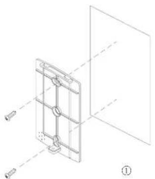
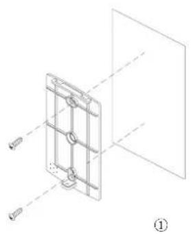
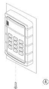
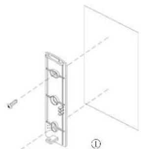
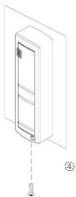
Please refer to Fig 2.1 to assist you with this portion of the installation. Fig. 2.1 (a), (b) and (c) show the mounting steps for the regular reader, keypad reader and mullion reader, respectively. The general rule is connecting the wires in the back of the reader first. Take off the cover box from the reader, and fix the baseboard on the wall with the screws (provided in the package) firmly (step 1). Then put the cover box of the reader back on the baseboard (step 2, 3). Finally mount the screw at the bottom of the reader (step 4. Both the screw and the spanner are provided in the package.)
natural_image
Technical line drawing of a mechanical assembly with mounting holes and internal components (no text or symbols)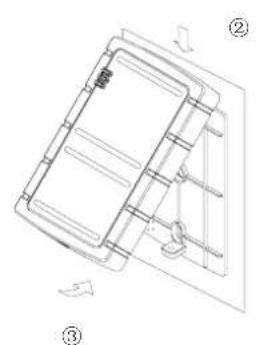
natural_image
Technical line drawing of a mechanical component with numbered annotations (no text or symbols)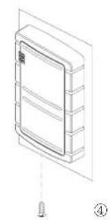
natural_image
Isometric line drawing of a wall-mounted cabinet with a screw base (no text or symbols)(a) Regular reader
natural_image
Technical line drawing of a mechanical assembly with no visible text or symbols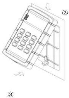
natural_image
Line drawing of a mobile phone with keypad and control panel, no text or symbols present(b) Keypad reader
natural_image
Technical line drawing of a mechanical assembly with no visible text or symbols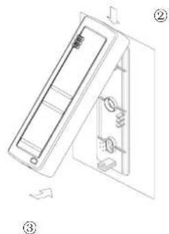
natural_image
Isometric line drawing of a refrigerator with labeled parts (no text or symbols)(c) Mullion reader
Figure 2.1 Reader mouting
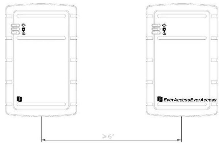
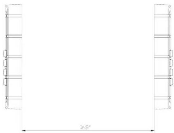
Note: Please keep reader from large metal for at least 2.4". Two reader scan NOT be installed side by side, or back to back with short distance. In case it is required to install the reader side by side, a minimum distance of 6" is recommended between readers. For the back-to-back case, the recommendation distance is 8" at least.
natural_image
Pure architectural line drawing of a symmetrical structure with no text, numbers, or symbolsData Format
This chapter will briefly introduce the format of reader's output.
Two formats can be used to transfer data from the readers to controllers: specialized RS-232 and wiegand 26. Specialized RS-232, specially designed for EverAccess system, is recommended for use to achieve the best performance.
Specialized RS-232
The data speed of specialized RS-232 is 9600 bps. All data including card information and keypad input has been combined together into a data packet. The data packet is transferred as ASCII character codes.
The length of one data packet is 22 bytes totally, which contains 1-byte packet header, 1-byte synchronization information, 16-byte card information, 1-byte keypad input, 1-byte tail (0x30) and 2-byte checksum. The last 2 bytes are the arithmetic checksum of the previous 20 bytes data.
Each new data packet will be transferred repeatedly for 50 times. After that, a single idle packet will be transmitted until some new data enters the system. The format of the idle packet is similar to the normal data packet except that card information bytes and keypad input bytes will be changed into 0x30, the same as the 1 byte packet tail.
| 1 2 3~18 19 20 21~22 | |||||
| Head | SYNC Card information | Keypad input | Tail | Check- sum | |
Figure 3.1 Specialized RS-232 packet format (byte)
Wiegand 26
As the name implies, each wiegand 26 packet contains 26 bit inside: 2 parity bits and 24-bit data. Please refer to Fig 3.2 for details. The 1^st bit is the even parity of sequential 12 bits and the last bit (the 26^th bit) is the odd parity of the 12-bit data before it
| 1 2~25 26 | ||
| Even parity | Data | Odd parity |
Figure 3.2 wiegand 26 format (bit)
Unlike specialized RS-232 format, the keypad input is processed separately from the card information. Each time the keypad is pressed, the data bus of Data 0 (green wire) and Data 1 (brown wire) will send out a corresponding digit combination, as Table 3.1 shows:
Table 3.1 Data 0 and Data1 combination for keypad input
| Keypad input Data 0 Data 1 | ||
| 1 | 0001 | 1110 |
| 2 | 0010 | 1101 |
| 3 | 0011 | 1100 |
| 4 | 0100 | 1011 |
| 5 | 0101 | 1010 |
| 6 | 0110 | 1001 |
| 7 | 0111 | 1000 |
| 8 | 1000 | 0111 |
| 9 | 1001 | 0110 |
| × | 1010 | 0101 |
| 0 | 0000 | 1111 |
| # | 1011 | 0100 |
Notes
EverFocus Electronics Corp.
Head Office
12F, No.79 Sec.1 Shin-Tai Wu Road, Hsi-Chi, Taipei, Taiwan
Tel :+ 886-2-26982334
Fax :+ 886-2-26982380
European Office
D-46446 Emmerich, German
Tel : +49-2822-9394-0
Fax : +49-2822-939495
USA Office
1801 Highland Ave.Duarte,CA
91010 ,U.S.A
Tel :+ 1-626-844-8888
Fax :+ 1-626-844-8838
Beijing office:
Room 609, Technology Trade Building.
Shangdi Information Industry Base,
Haidian District, Beijing China
Tel :+ 86-10-62971096
Fax :+ 86-10-62971423
Japan Office
1809 WBG Marive East 18F,
2-6 Nakase, Mihama-ku,
Chiba city 261-7118, Japan
- EverAccess Proximity Readers
- Table of Contents
- CHAPTER 1
- CHAPTER 2
- CHAPTER 3
- Product Overview
- Features
- Parts List
- Installation
- Wiring Connections
- Connection to Controller
- Basic Mounting Instructions
- Data Format
- Specialized RS-232
- Wiegand 26
- EverFocus Electronics Corp.
- Head Office
- European Office
- USA Office
- Beijing office:
- Japan Office
Brand : EverFocus
Model : ERM-871
Category : Access Control System