
IMZNS104 - Security management software SONY - Free user manual and instructions
Find the device manual for free IMZNS104 SONY in PDF.


| Product Type | System Controller for Security Management Software |
| Model | RM-NS1000 (IMZNS104) |
| Dimensions (W x H x D) | 409.0 x 111.5 x 170.0 mm (16 1/8 x 4 1/2 x 6 3/4 in.) |
| Weight | Approx. 1,200 g (2.6 lb) |
| Power Supply | 12 V DC, max. 1.0 A; AC adapter: 100-240 V AC, 50/60 Hz |
| Interface | USB 2.0 low-speed device |
| External Connectors | USB 2.0 (x2), Microphone jack, Headphone jack, RS-485 port |
| Operating Temperature | 5 °C to 40 °C (41 °F to 104 °F) |
| Operating Humidity | 20% to 80% (max. wet bulb temp: 32 °C / 90 °F, no condensation) |
| Main Functions | Pan/Tilt/Zoom camera control, camera presets, camera tours (including shadow tours), layout tours, recording, playback (including jog/shuttle), search, export (video and still images), alarm history, audio output, system lock, multi-function LCD menu |
| Modes | RM-NS1000 mode (for NSR-1000 series or RealShot Manager Advanced) and Pelco mode (for direct Pelco-D/P cameras via RS-485) |
| Maintenance | Indoor use only; avoid excessive force on joystick; protect from smoke, steam, moisture, and dust |
| Safety | Operation lock function to prevent unauthorized use; password protection available |
| Spare Parts & Repairability | No user-serviceable parts; refer to qualified service personnel |
| General Information | USB cable connection to surveillance server or computer; supports up to 30-minute auto-off timer |
Frequently Asked Questions - IMZNS104 SONY
User questions about IMZNS104 SONY
0 question about this device. Answer the ones you know or ask your own.
Ask a new question about this device
Download the instructions for your Security management software in PDF format for free! Find your manual IMZNS104 - SONY and take your electronic device back in hand. On this page are published all the documents necessary for the use of your device. IMZNS104 by SONY.
USER MANUAL IMZNS104 SONY
Before operating the unit, please read this manual thoroughly and retain it for future reference.
RM-NS1000
IPELA
Table of Contents
Chapter 1 Introduction
Function Overview......5
Precautions and Limitations....7
Supported Systems 7
Names of Parts....8
Control Panel....8
Left Side 10
Rear 11
Bottom 11
Chapter 2 Operations in RM-NS1000 Mode
Overview....12
Logging On to the System 12
Viewing and Using the LCD 14
Viewing the LCD 14
Operating the Multi Function Menu.... 14
Switching Modes ....15
Operations in the Main Screen 16
Selecting a Monitor Frame....18
Selecting a Camera....19
Assigning Cameras to Monitoring Frames ....19
Switching between Monitoring Live Images and Playing Recorded Images ....20
Setting the Joystick to Mouse Mode....21
Controlling Cameras ....21
Performing Pan, Tilt, and Zoom Operations 21
Returning All Cameras to Preset Position 1....22
Using the Digital Zoom.... 22
Using Manual Focus.... 23
Using Auto Focus.... 23
Adjusting the Brightness of Images 23
Setting Image Brightness Adjustment to Auto Mode 23
Using Camera Presets....24
Moving a Camera to a Preset Position 24
Setting a New Preset Position 24
Performing a Camera Tour ....25
Performing Camera Tours 25
Performing Shadow Tours.... 26
Performing a Layout Tour....27
Outputting Audio to the Camera 28
Recording, Searching for, and Playing Back Images.....29
Recording Live Images 29
Using the Jog/Shuttle Dial.... 30
Playing Back Recorded Images.... 31
Operations in the Search Screen.... 35
Searching for Recorded Images 36
Playing Back Recorded Images from Search Results 38
Exporting Recorded Images 38
Exporting Recorded Images 38
Exporting Recorded Images as Still Images.... 41
Locking Operation ....41
To Lock Operation 41
To Unlock the Lock.... 42
Setting the System Controller to the Off State ....42
Adjusting the Brightness of the LCD....43
Adjusting the Brightness and Contrast.... 43
Turning On/Off the code number indication.... 43
Multi Function Menu....44
Monitor Layout.... 45
Device....45
Volume 47
System Lock 48
Button Confirmation.... 50
System Menu.... 51
Chapter 3 Operations in Pelco Mode
Overview....52
Viewing and Using the LCD 52
Viewing the LCD 52
Operating the Multi Function Menu.... 53
Switching Modes ....53
Selecting a Camera....54
Controlling Cameras ....55
Performing Pan, Tilt, and Zoom Operations 55
Using Manual Focus.... 55
Adjusting the Brightness of Images 55
Locking Operation ....56
To Lock Operation 56
To Unlock the Lock.... 56
Setting the System Controller to the Off State ....57
Adjusting the Brightness of the LCD....57
Multi Function Menu....58
Protocol 59
Baudrate....59
System Lock 60
System Menu....62
Chapter 4 Other Information
Screen Index 63
RM-NS1000 Mode 63
Pelco Mode....68
I/O Port....70
Troubleshooting....70
Specifications ....71
Dimensions ....71
Trademarks
- “IPELA” and are trademarks of Sony Corporation.
Other products or system names appearing in this document are trademarks or registered trademarks of their respective owners.
Further, the Ⓡ, or ™ symbols are not used in the text.
Introduction
Chapter
1
Function Overview
The RM-NS1000 system controller is a system controller for remotely operating various functions of a surveillance system. Connect it to the surveillance server or the computer used for remote operations in order to perform operations such as monitoring or searching for and playing back recorded images.
The system controller has RM-NS1000 mode, and Pelco mode to select from in accordance with your surveillance server, software, and cameras.
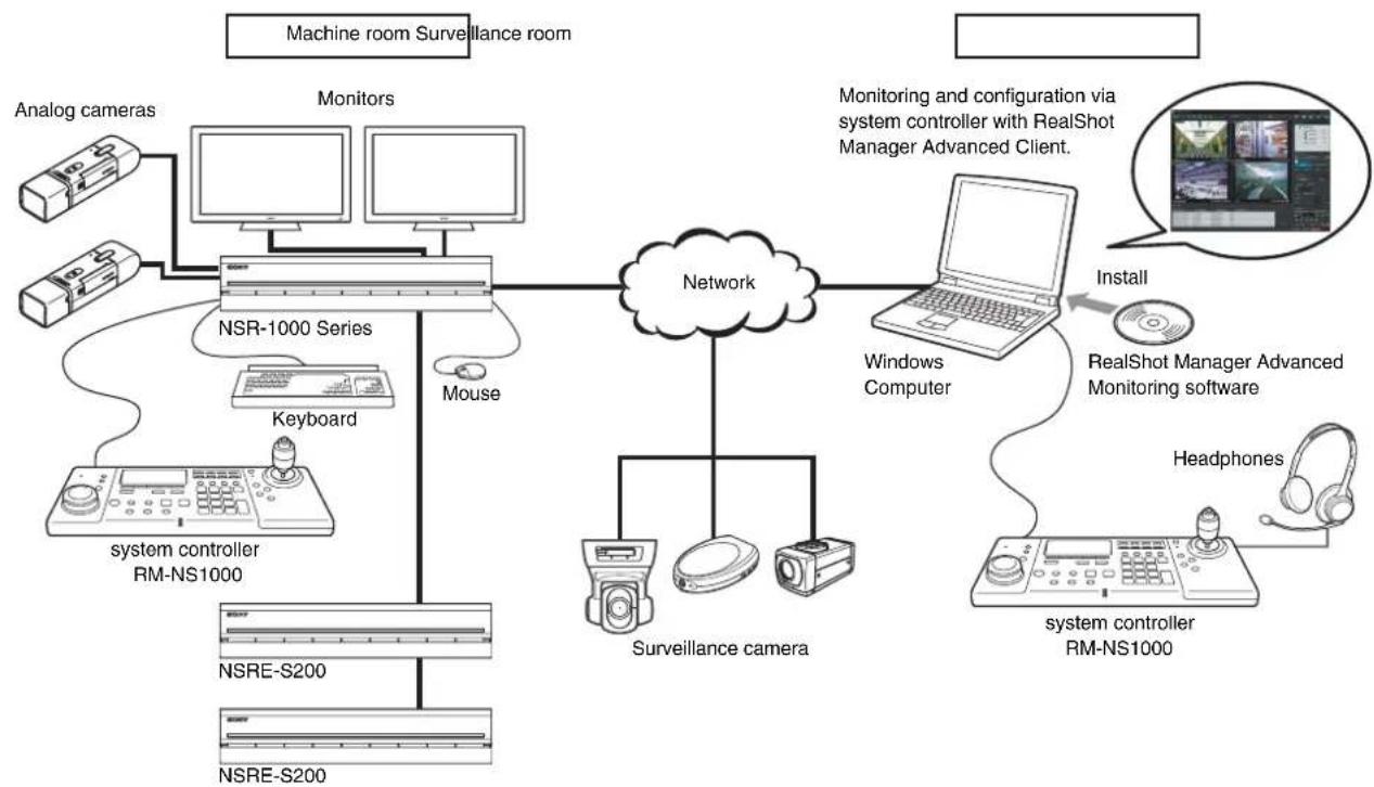
Configuration example in RM-NS1000 mode:
When using the NSR-1000 series or RealShot Manager Advanced, perform operation in RM-NS1000 mode.
flowchart
graph TD
    A["Machine room Surveillance room"] --> B["Monitors"]
    B --> C["NSR-1000 Series"]
    C --> D["Mouse"]
    D --> E["Network"]
    E --> F["Surveillance camera"]
    F --> G["Windows Computer"]
    G --> H["Install"]
    H --> I["RealShot Manager Advanced Monitoring software"]
    I --> J["Headphones"]
    J --> K["system controller RM-NS1000"]
    K --> L["nsreS200"]
    L --> M["NSRE-S200"]
    M --> N["nsreS200"]
    N --> O["sysmtcontroller RM-NS1000"]
    O --> P["nsreS200"]
    P --> Q["nsreS200"]
    Q --> R["sysmtcontroller RM-NS1000"]
    R --> S["nsreS200"]
    S --> T["sysmtcontroller RM-NS1000"]
    T --> U["nsreS200"]
    U --> V["sysmtcontroller RM-NS1000"]
    V --> W["nsreS200"]
    W --> X["sysmtcontroller RM-NS1000"]
    X --> Y["nsreS200"]
    Y --> Z["sysmtcontroller RM-NS1000"]
    Z --> AA["nsreS200"]
    AA --> AB["sysmtcontroller RM-NS1000"]
    AB --> AC["nsreS200"]
    AC --> AD["sysmtcontroller RM-NS1000"]
    AD --> AE["nsreS200"]
    AE --> AF["sysmtcontroller RM-NS1000"]
    AF --> AG["nsreS200"]
    AG --> AH["sysmtcontroller RM-NS1000"]
    AH --> AI["nsreS200"]
    AI --> AJ["sysmtcontroller RM-NS1000"]
    AJ --> AK["nsreS200"]
    AK --> AL["sysmtcontroller RM-NS1000"]
    AL --> AM["nsreS200"]
    AM --> AN["sysmtcontroller RM-NS1000"]
    AN --> AO["nsreS200"]
    AO --> AP["sysmtcontroller RM-NS1000"]
    AP --> AQ["nsreS200"]
    AQ --> AR["sysmtcontroller RM-NS1000"]
    AR --> AS["nsreS200"]
    AS --> AT["sysmtcontroller RM-NS1000"]
    AT --> AU["nsreS200"]
    AU --> AV["sysmtcontroller RM-NS1000"]
    AV --> AW["nsreS200"]
    AW --> AX["sysmtcontroller RM-NS1000"]
    AX --> AY["nsreS200"]
    AY --> AZ["sysmtcontroller RM-NS1000"]
    AZ --> BA["nsreS200"]
    BA --> BB["sysmtcontroller RM-NS1000"]
    BB --> BC["nsreS200"]
    BC --> BD["sysmtcontroller RM-NS1000"]
    BD --> BE["nsreS200"]
    BE --> BF["sysmtcontroller RM-NS1000"]
    BF --> BG["nsreS200"]
    BG --> BH["sysmtcontroller RM-NS1000"]
    BH --> BI["nsreS200"]
    BI --> BJ["sysmtcontroller RM-NS1000"]
    BJ --> BK["nsreS200"]
    BK --> BL["sysmtcontroller RM-NS1000"]
    BL --> BM["nsreS200"]
    BM --> BN["sysmtcontroller RM-NS1000"]
    BN --> BO["nsreS200"]
    BO --> BP["sysmtcontroller RM-NS1000"]
    BP --> BQ["nsreS200"]
    BQ --> BR["sysmtcontroller RM-NS1000"]
    BR --> BS["nsreS200"]
    BS --> BT["sysmtcontroller RM-NS1000"]
    BT --> BU["nsreS200"]
    BU --> BV["sysmtcontroller RM-NS1000"]
    BV --> BW["nsreS200"]
    BW --> BX["sysmtcontroller RM-NS1000"]
    BX --> BY["nsreS200"]
    BY --> BZ["sysmtcontroller RM-NS1000"]
    BZ --> CA["nsreS200"]
    CA --> CB["sysmtcontroller RM-NS1000"]
    CB --> CC["nsreS200"]
    CC --> CD["sysmtcontroller RM-NS1000"]
    CD --> CE["nsreS200"]
    CE --> CF["sysmtcontroller RM-NS1000"]
    CF --> CG["nsreS200"]
    CG --> CH["sysmtcontroller RM-NS1000"]
    CH --> CI["nsreS200"]
    CI --> CJ["sysmtcontroller RM-NS1000"]
    CJ --> CK["nsreS200"]
Note
A keyboard and mouse are required when logging on to the NSR-1000 series or RealShot Manager Advanced.
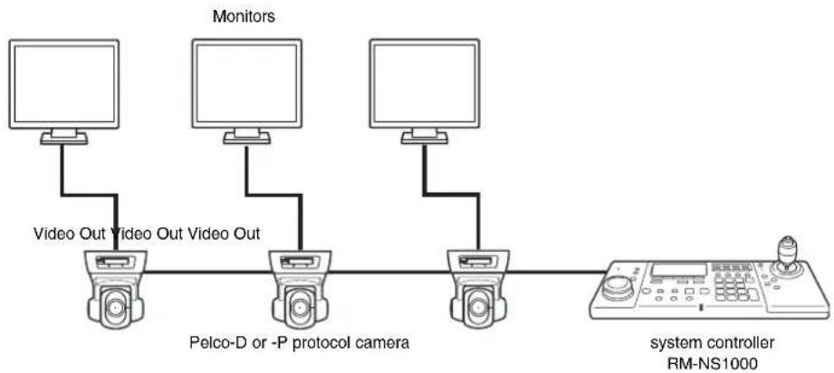
Configuration example in Pelco mode:
When connecting a Pelco-D or -P protocol camera directly to the system controller via the RS-485 port to perform pan, tilt, and zoom control, perform operation in Pelco mode.
flowchart
graph LR
    A["Monitor"] -->|Video Out| B["Pelco-D or -P protocol camera"]
    C["Monitor"] -->|Video Out| B
    D["Monitor"] -->|Video Out| B
    B --> E["system controller RM-NS1000"]
    E --> F["End"]
Highly functional system controller with support for two modes
The system controller is provided with RM-NS1000 mode, and Pelco to select from in accordance with your surveillance server, software, and cameras. You can operate various functions remotely such as monitoring, searching, and playback.
Changing the screen (layout)
You can change the screen layout when your are monitoring live images or playing back recorded images.
Selecting a camera
You can use the numeric keypad or joystick to select the camera to control.
Camera control
You can perform operations such as panning, tilting, and zooming, adjusting the focus and iris, and presetting camera positions.
Panning, tilting, and zooming are performed by moving the joystick up, down, left, and right.
Recording images, and playing back and searching for recorded images
You can remotely perform operations such as recording images and playing back, pausing, and frame-by-frame forwarding recorded images. It is also possible, for example, to switch the screen display (live/playback) mode and search for and export recorded images.
System controller operation lock
When, for instance, you leave your seat during operation, you can lock system controller operation to prevent other people performing operations.
Precautions and Limitations
- The joystick is a precision part, so do not use excessive force when operating it. Doing so may result in a malfunction.
- The system controller is designed to be used indoors. Refrain from using it outdoors.
- Use in locations with excessive smoke, steam, moisture, or dust may result in a malfunction.
Supported Systems
The system controller supports the following systems.
- Sony NSR-1000-Series Network Surveillance Server (Version 1.1 or later)
- A computer on which RealShot Manager Advanced (Version 1.1 or later), an application software with controls compatible with this equipment, is installed
Names of Parts
Control Panel
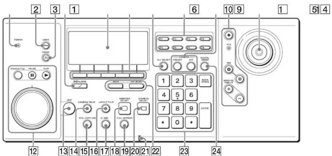
1 POWER LED
Lights green when the AC adapter is connected to an outlet.
2 (LOCK) button
Locks or unlocks system controller operation.
For the operating procedure, see "Locking Operation" (page 41).
3 (PANIC) button
Returns all cameras to preset position 1.
4 (ALARM) button
Used when you use the joystick to select the alarm history.
5LCD
Used to check the current status and operate each of the items in the multi function menu.
6 Multi function buttons
Used to select/execute each of the items in the multi function menu.
For the operating procedure, see “Viewing and Using the LCD” (page 14).
7 (ALL SELECT) button
Selects all monitor frames.
8 Custom function buttons
Used to access pre-registered functions.
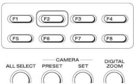
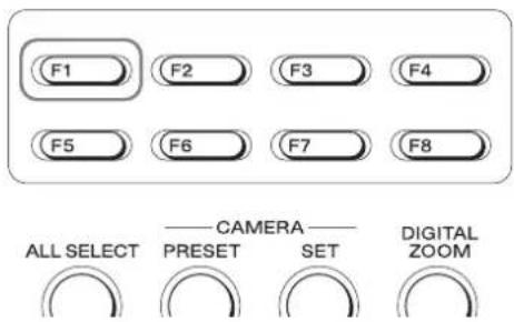
F1: Sets image brightness adjustment to auto mode.
F2: Turns the auto focus on.
F3: Turns the DIRECT operations on or off.
F4 to F8: These buttons are not used.
⑨ Camera preset area
Used to move cameras to preset positions, and configure preset positions.
PRESET
○ (PRESET) button
Moves the selected camera to the preset position.
SET (SET) button
The current camera position is set as the preset position.
10 Camera control area
Used to control cameras.
For the operating procedure, see "Controlling Cameras" (page 21).
(CURSOR) button/LED
Sets the joystick to mouse mode.
If mouse mode is set, the joystick can be operated in the same way as a mouse.
In mouse mode, the LED is lit green.
PTZ LED
This LED is lit green when pan, tilt, and zoom operations can be performed.
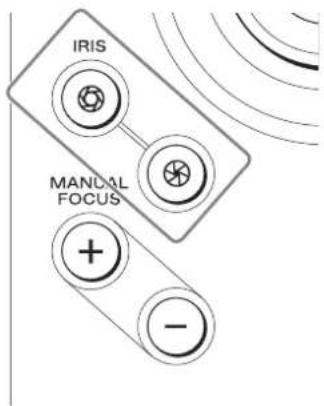
IRIS buttons
Adjusts the aperture of the currently selected camera to change the brightness.
Adjust the aperture in the direction to make the images brighter, and adjust it in the direction to make the images darker.
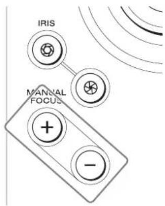
MANUAL FOCUS buttons
Adjust the focus of the camera currently selected. Press ☑ when you want to focus on an object in the distance and press ☑ when you want to focus on an object nearby.
11Joystick
Used to select monitor frames and cameras, and perform camera pan, tilt, and zoom operations. You can use the top button as follows.
When PTZ LED is lit: Return selected cameras to preset position 1.
When PTZ LED is not lit: Confirm selections and operations.
12Search and playback area
Used to search for and play back recorded images.
JOG/SHUTTLE

(JOG/SHUTTLE) button/LED
Enables or disables the jog/shuttle dial.
When lit: Enabled
When not lit: Disabled
Note
If the button is pressed to turn on the LED when the currently selected monitor frame is PLAYBACK, the recorded images are paused or played back at +/- speed according to the position of the shuttle ring.
PAUSE

(PAUSE) button
Pauses playback.
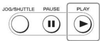
PLAY

(PLAY) button
Plays the recorded images of the selected monitor frame.
Jog/shuttle dial
Used to change the playback speed and to frame-by-frame forward/rewind during the playback of recorded images.
The top part is the jog dial and the bottom part is the shuttle ring.
For how to use the jog dial and shuttle ring, see “Using the Jog/Shuttle Dial” (page 30).
Note
The jog dial and shuttle ring can only be used when the JOG/SHUTTLE LED is lit.
Switches the selected monitor frame to live images.
CAMERA TOUR

Starts or stops the camera tour.
For the operating procedure, see “Performing a Camera Tour” (page 25).
STILL CAPTURE

Captures one scene of recorded or live images and exports it as a still image file.
For the operating procedure, see “Exporting Recorded Images as Still Images” (page 41).
LAYOUT TOUR

Starts or stops a registered layout tour.
For the operating procedure, see “Performing a Camera Tour” (page 25).
While this button is pressed, the LED is lit green and audio is sent to the camera.
(This function is only available with RealShot Manager Advanced.)
MONITOR SELECT

Used to select the monitor frame.
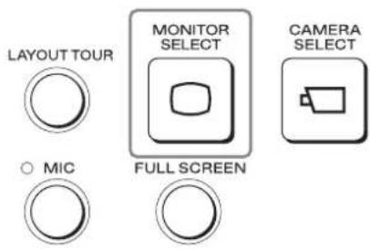
For the operating procedure, see “Selecting a Monitor Frame” (page 18).
FULL SCREEN

Displays the current layout (monitor frame arrangement) over the whole screen.
Switching to full screen hides the pane, control buttons, and other items.
CAMERA

Used to assign a camera to a monitor frame.
For the operating procedure, see “Selecting a Camera” (page 19).
21Microphone
This is the built-in microphone.
22BACK button/TOP MENU button
Displays the multi function menu that is shown on the LCD.
(This function is only available with RealShot Manager Advanced.)
For the operating procedure, see “Viewing and Using the LCD” (page 14).

(BACK) button
Redisplays the previous multi function menu screen.

(TOP MENU) button
Redisplays the top menu.
23Numeric keypad
Used to enter numbers.
DIGITAL ZOOM
24 (DIGITAL ZOOM) button
Turns the digital zoom on or off.
Left Side
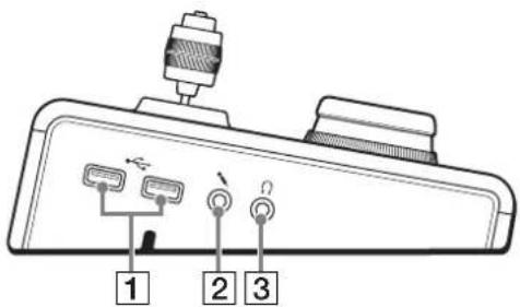
1 USB ports
Connect a USB keyboard, USB mouse, or USB flash memory.
② Microphone input jack
Input audio from a microphone. This jack supports plug-in-power microphones.
Note
This jack functions only with RealShot Manager Advanced.
3Headphone jack
Connect headphones.
Note
This jack functions only with RealShot Manager Advanced.
Rear
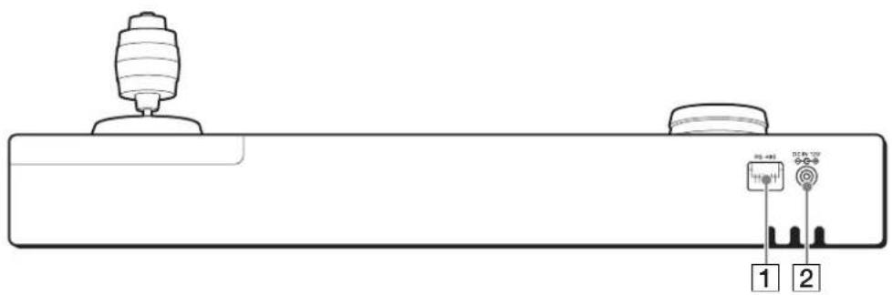
1RS-485 port
Used to control Pelco-D or -P protocol cameras. For the connection procedure, see "I/O Port" (page 70).
②Power supply connector
Connect the supplied AC adapter.
Bottom
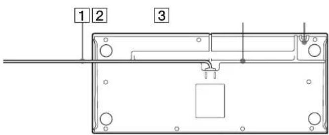
1 USB cable
Connect this cable to a USB port of the NSR-1000 series or a computer with RealShot Manager Advanced installed.
3 AC cord holder
Wrap the AC adapter cord around the holder to secure the cord.
②USB cable holder
Thread the USB cable through the groove in accordance with the location that the system controller is placed.
Operations in RM-NS1000 Mode
Chapter
2
Overview
RM-NS1000 mode is for when you are operating the NSR-1000 series or RealShot Manager Advanced.
This chapter describes the following operations in RM-NS1000 mode.
- Logging On to the System (page 12)
• Viewing and Using the LCD (page 14) - Switching Modes (page 15)
- Operations in the Main Screen (page 16)
- Selecting a Monitor Frame (page 18)
- Selecting a Camera (page 19)
- Assigning Cameras to Monitoring Frames (page 19)
- Switching between Monitoring Live Images and Playing Recorded Images (page 20)
- Controlling Cameras (page 21)
• Using Camera Presets (page 24)
• Performing a Camera Tour (page 25)
• Performing a Layout Tour (page 27) - Outputting Audio to the Camera (page 28)
- Recording, Searching for, and Playing Back Images (page 29)
- Exporting Recorded Images (page 38)
- Locking Operation (page 41)
- Setting the System Controller to the Off State (page 42)
- Adjusting the Brightness of the LCD (page 43)
- Multi Function Menu (page 44)
Note
In this chapter, mainly the screens of RealShot Manager Advanced are used for the explanations. These screens are subject to change without notice.
Logging On to the System
Turn on the power of the system controller, and log on to the NSR-1000 series or RealShot Manager Advanced.
Note
A keyboard and mouse are required when logging on to the NSR-1000 series or RealShot Manager Advanced. If the user name and password consist only of numbers, you can use the numeric keypad of the system controller to log on.
When a password is not set for the system controller
1 Connect the AC adapter of the system controller to an outlet.
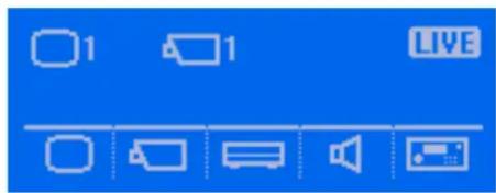
The power of the system controller turns on and the top screen appears.
2 Log on to the system.
Use the keyboard to enter your user name and password, and click [Logon].
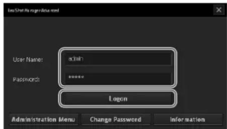
If authentication is successful, the Main screen appears.
3 Enter the system controller password with the numeric keypad, and press the ENTER key.
When a password is set for the system controller
1 Connect the AC adapter of the system controller to an outlet.
When the power turns on, the following screen appears and the system controller enters a locked state.
If the password is authenticated, the top screen appears.
4 Log on to the system.
Use the keyboard to enter your user name and password, and click [Logon].
2 Press the LOCK button.
A screen requesting you to enter the password appears.
If authentication is successful, the Main screen appears.
Viewing and Using the LCD
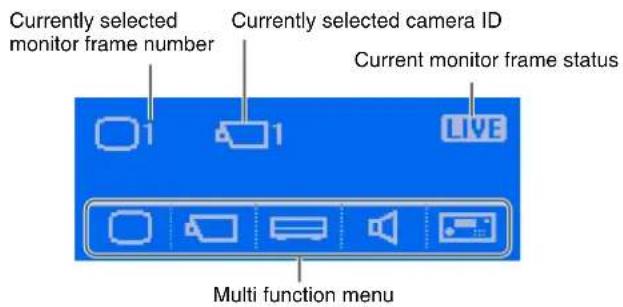
On the LCD, you can check the current status and operate the multi function menu.
Viewing the LCD
Top screen
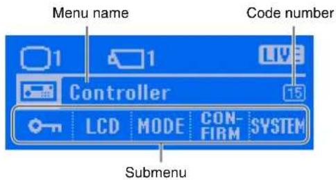
When you have entered the multi function menu
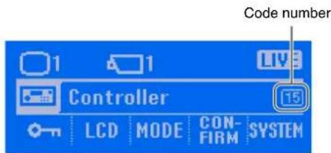
Example: Controller screen
Note
Code numbers are numbers to help you refer to this guide. For details on how to use code numbers, see "Screen Index" (page 63).
Operating the Multi Function Menu
Each item of the multi function menu corresponds to one of the multi function buttons below the LCD.
When you want to select or operate an item of the multi function menu, press the button directly below the item to display a screen that corresponds with that item.
Example: When operating the menu
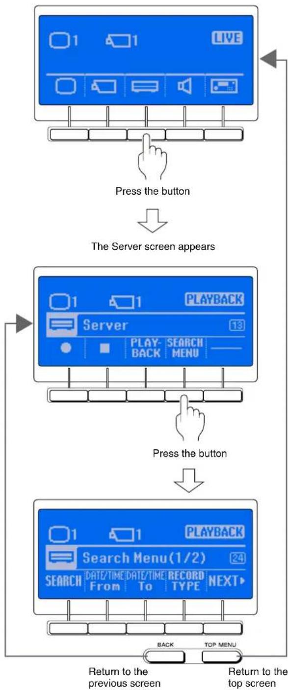
flowchart
graph TD
    A["Start Screen"] --> B["Press the button"]
    B --> C["The Server screen appears"]
    C --> D["Press the button"]
    D --> E["Return to the previous screen"]
    E --> F["Return to the top screen"]
Switching Modes
Switch to RM-NS1000 mode or Pelco mode in accordance with the devices you are using.
1 Press the button.
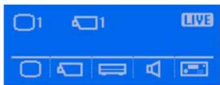
The Controller menu screen appears.
2 Press the (MODE) button.
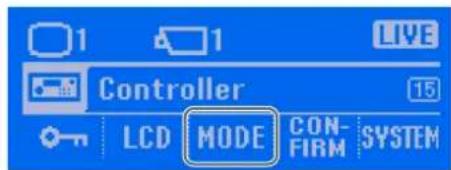
The Mode screen appears.
3 Press the button for the mode to which you want to switch.
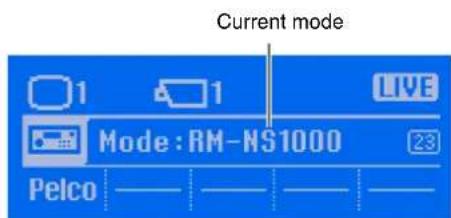
If a password is set, a screen requesting you to enter the password appears. Go to step 4. If a password is not set, a confirmation screen appears. Go to step 5.
4 Enter the password with the numeric keypad, and press the ENTER key.
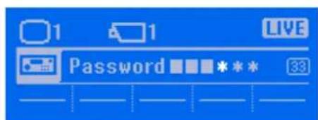
If the password is authenticated, a confirmation screen appears.
5 Press the (OK) button.
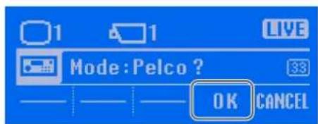
The setting complete screen appears, and the "Completed" indication appears.
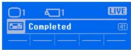
The mode is switched, and the top screen of the selected mode appears.
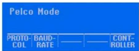
Operations in the Main Screen
The Main screen of the NSR-1000 series and RealShot Manager Advanced and the system controller are linked as shown below.
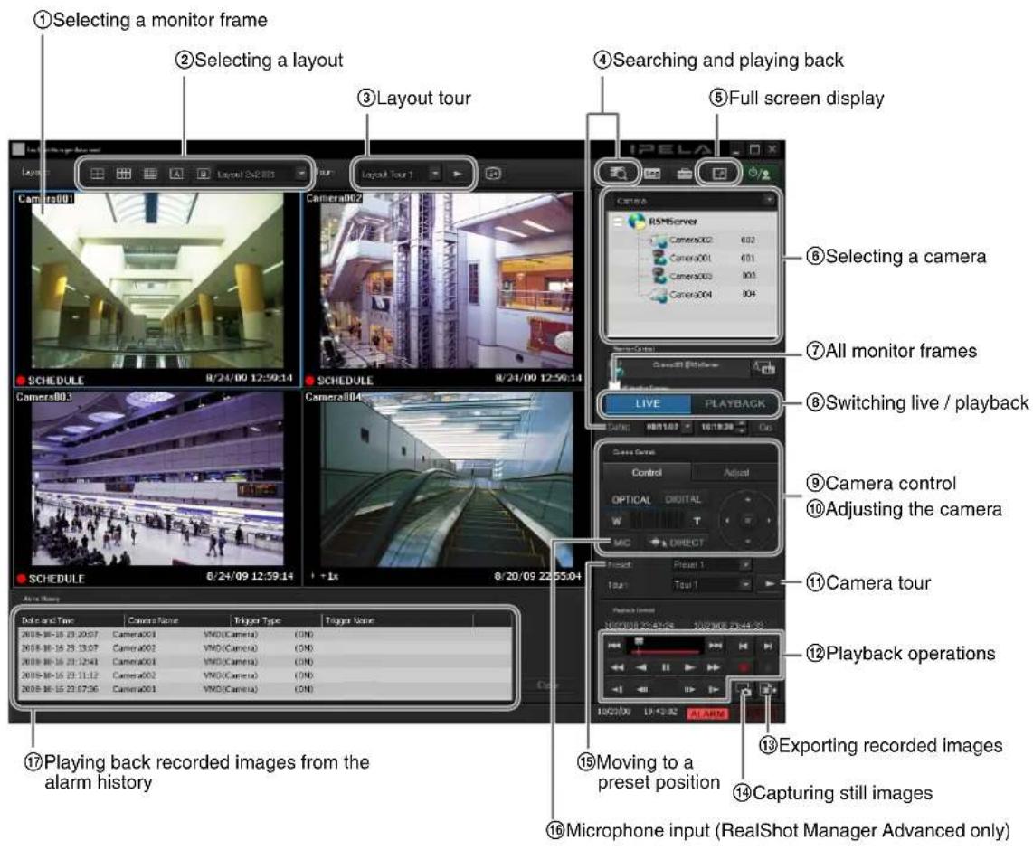
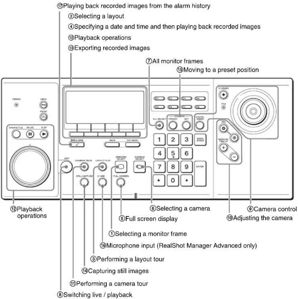
For details on the operations, see the following pages.
| Operation Reference | Page | |
| 1 | Selecting a monitor frame | 18, 19 |
| 2 | Selecting a layout 45 | |
| 3 | Performing a layout tour 27 | |
| 4 | Specifying a date and time and then playing back recorded images | 32 |
| 5 | Full screen display 18 | |
| 6 | Selecting a camera 19 | |
| 7 | All monitor frames 8 | |
| 8 | Switching live / playback 20 | |
| 9 | Camera control 21 | |
| 10 | Adjusting the camera 21 | |
| 11 | Performing a camera tour 25 | |
| 12 | Playback operations 31 | |
| 13 | Exporting recorded images 38 | |
| 14 | Capturing still images | 41 |
| 15 | Moving to a preset position | 24 |
| Operation Reference | Page | |
| 16 | Microphone input (RealShot Manager Advanced only) | 28 |
| 17 | Playing back recorded images from the alarm history | 33 |
Selecting a Monitor Frame
Use the numeric keypad or joystick to select a monitor frame.
1 Press the (MONITOR SELECT) button.
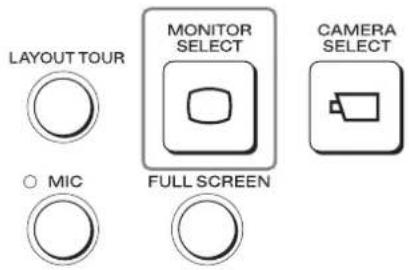
The following screen appears.
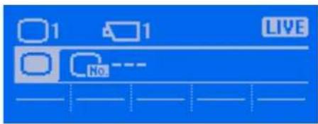
At the same time, a monitor frame number appears in each of the monitor frames in the Main screen.
2 Select a monitor frame.
To select with the numeric keypad:
Enter the monitor frame number, and press the ENTER key.
To select with the joystick:
Move the joystick left or right to select the monitor frame, and press the top button.
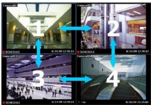
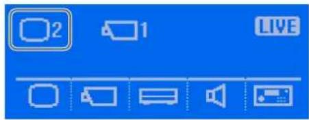
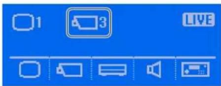
The light blue frame moves to the selected monitor frame, and the selected monitor frame number appears in the screen on the LCD.
Example: When monitor frame 2 is selected
Selecting a Camera
Select the camera for the live images you want to monitor or recorded images you want to play.
You can use the joystick or numeric keypad to select the camera.
1 Select the monitor frame in which to display the camera images.
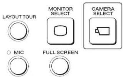
2 Press the (CAMERA SELECT) button.
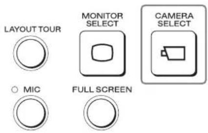
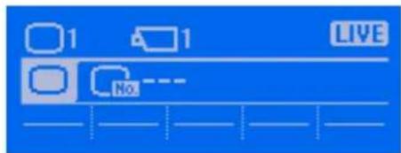
The following screen appears.
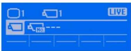
3 Enter the camera ID with the numeric keypad, and press the ENTER key.
The images of the selected camera appear in the monitor frame, and the selected camera ID appears in the screen on the LCD.
Example: When "003" is entered and selected
Assigning Cameras to Monitoring Frames
You can select a monitor frame and assign a camera.
1 Press the (MONITOR SELECT) button.
The following screen appears.
At the same time, a monitor frame number appears in each of the monitor frames in the Main screen.
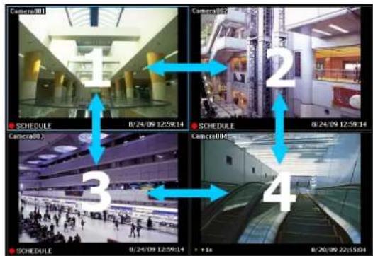
2 Enter the monitor frame number with the numeric keypad.
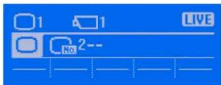
Assign a camera next.
3
Press the (CAMERA SELECT) button.
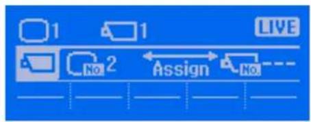
The light blue frame moves to the selected monitor frame, and the next screen appears.
flowchart
graph LR
    A["1"] --> B["2"]
    B --> C["LIVE"]
    style A fill:#fff,stroke:#000
    style B fill:#fff,stroke:#000
    style C fill:#fff,stroke:#000
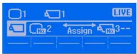
4 Enter the camera ID with the numeric keypad.
flowchart
graph LR
    A["1"] --> B["2"]
    B --> C["3"]
    style A fill:#fff,stroke:#000
    style B fill:#fff,stroke:#000
    style C fill:#fff,stroke:#000
5 Press the ENTER key. The camera is assigned to the monitor frame.
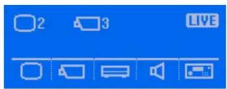
Switching between Monitoring Live Images and Playing Recorded Images
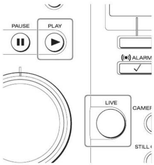
You can switch the status of the selected monitor frame (monitoring live images and playing recorded images).
Switching to live images
Press the LIVE button.
Switching to playing recorded images
Press the PLAY button.
Setting the Joystick to Mouse Mode
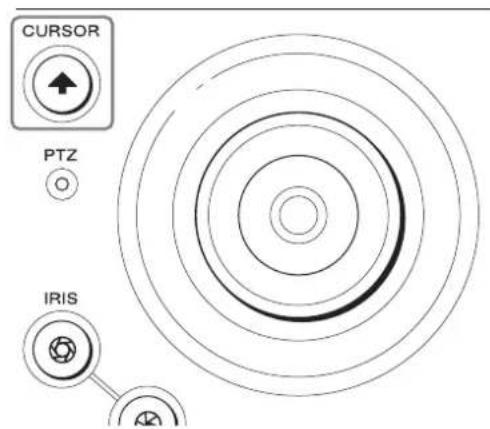
If the mouse mode is set, you can perform mouse operations using the joystick.
Press the (CURSOR) button.
The LED is lit green, and the joystick enters mouse mode.
Controlling Cameras
For a camera equipped with pan and tilt functions, you can monitor the images from the camera while performing operations such as panning, tilting, and zooming.
Note
The PTZ LED on the system controller lights green when pan, tilt, and zoom operations can be performed.
Performing Pan, Tilt, and Zoom Operations
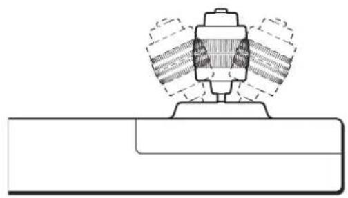
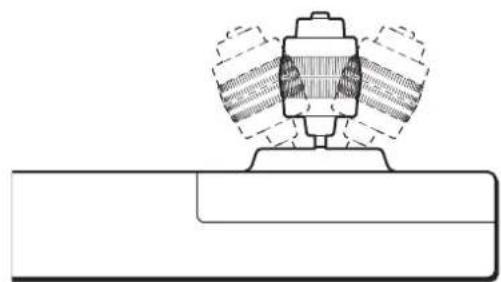
The panning and tilting operations are achieved by moving the joystick in the direction in which you want the camera to face.
Panning
Move the joystick right or left.
Front view
natural_image
Technical line drawing of a mechanical assembly with no visible text or symbolsTilting
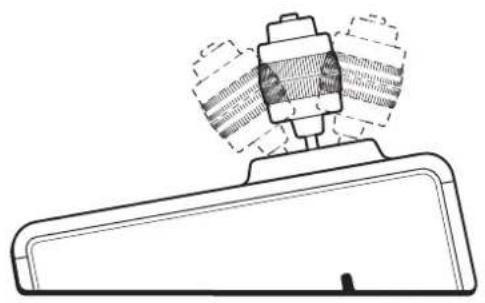
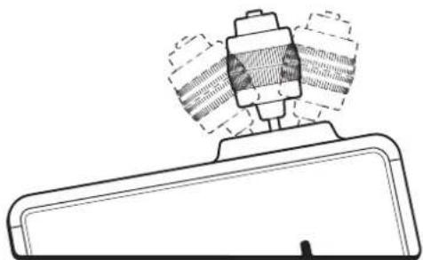
Move the joystick up or down.
Right view
natural_image
Technical line drawing of a mechanical component with no visible text or symbolsZooming
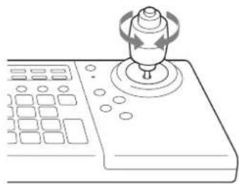
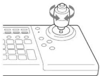
Rotate the z-axis of the joystick clockwise to zoom in (Tele), and rotate it counterclockwise to zoom out (Wide).
natural_image
Line drawing of a joystick controller with scroll wheel and control buttons (no text or symbols)Returning All Cameras to Preset Position 1
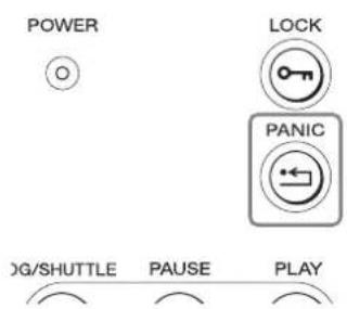
Press the PANIC button to return all PTZ cameras that are displayed in the camera tree on the NSR-1000 series or RealShot Manager Advanced to preset position 1.
Using the Digital Zoom
You can also perform digital pan and tilt during digital zoom.
1 Press the DIGITAL ZOOM button.
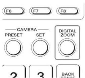
If the [Camera Control] pane is displayed, [DIGITAL] lights.
2 Use the joystick to operate pan, tilt, and zoom.
Panning
Move the joystick right or left.
Front view
natural_image
Technical line drawing of a mechanical assembly with no visible text or symbolsTilting
Move the joystick up or down.
Right view
natural_image
Technical line drawing of a mechanical component with no visible text or symbolsZooming
Rotate the z-axis of the joystick clockwise to zoom in (Tele), and rotate it counterclockwise to zoom out (Wide).
natural_image
Line drawing of a joystick controller with control panel and scroll wheel (no text or symbols)Returning to optical zoom
Press the DIGITAL ZOOM button again.
Using Manual Focus
You can use the MANUAL FOCUS button to adjust the focus manually.
Press when you want to focus on an object in the distance and press when you want to focus on an object nearby.
Note
When you use the MANUAL FOCUS buttons, adjustment enters manual mode.
Using Auto Focus
Press the F2 button to set focus adjustment to auto mode.
Adjusting the Brightness of Images
Adjust the iris of the camera to change the brightness. Adjust the aperture in the direction to make the images brighter, and adjust it in the direction to make the images darker.
Note
When you use the IRIS buttons, adjustment enters manual mode.
Setting Image Brightness Adjustment to Auto Mode
Press the F1 button to set brightness adjustment to auto mode.
Using Camera Presets
You can move a camera to preset positions stored on the camera.
It is also possible to set new preset positions.
Moving a Camera to a Preset Position
1 Select any monitor frame, and display the images of the camera you want to control.
2 Press the PRESET button.
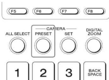
The Camera Preset screen appears.
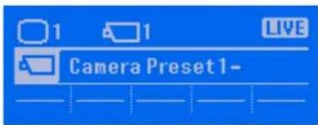
3 Select a preset.
To select with the numeric keypad:
Enter the preset number, and press the ENTER key.
To select with the joystick:
Select a preset in the [Camera Control] pane, and press the top button.
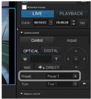
The camera moves to the preset position.
Setting a New Preset Position
1 Select any monitor frame, and display the images of the camera you want to control.
2 Perform pan, tilt, and zoom operations to move the camera to the desired position.
3 Press the SET button.
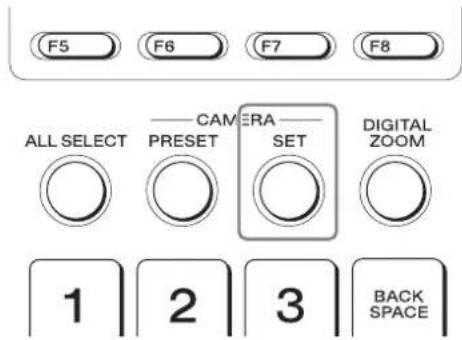
The Camera Set screen appears.
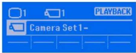
4 Enter the preset number with the numeric keypad, and press the ENTER key.
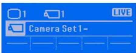
The current camera position is set as the preset position.
Performing a Camera Tour
You can perform a tour to move a camera to the pan, tilt, and zoom positions specified for presets in order. The camera only stops at each preset position for the duration set in advance. You can also record camera movements using the shadow tour function, and perform shadow tours that reproduce these movements.
Performing Camera Tours
Note
To use the camera tour function, a camera tour needs to be set in advance. For the setting procedure, see the user's guide for your NSR-1000 series or RealShot Manager Advanced.
1 Select any monitor frame, and display the images of the camera you want to control.
2 Press the CAMERA TOUR button.
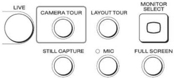
The Camera Tour screen appears.
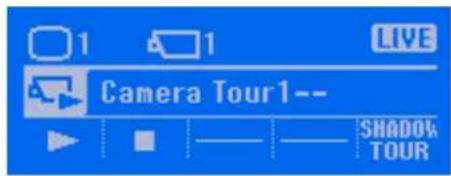
3 Select a camera tour.
To select with the numeric keypad:
Enter the tour number, and press the ENTER key.
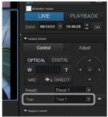
To select with the joystick:
Select a tour in the [Camera Control] pane of the Main screen, and press the top button.
4 Press the camera tour button.
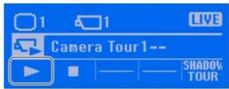
The camera tour starts.
5 Press the button when you want to end the camera tour.
Performing Shadow Tours
Note
To use the shadow tour function, a shadow tour needs to be set in advance. For the setting procedure, see “Shadow tours (Shadow Tour)” (page 47).
1 Select any monitor frame, and display the images of the camera you want to control.
2 Press the CAMERA TOUR button.
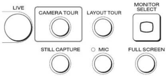
The Camera Tour screen appears.
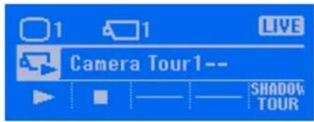
3 Press the (SHADOW TOUR) button.
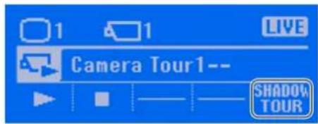
The Shadow Tour screen appears.
4 Select a shadow tour.
To select with the numeric keypad:
Enter the tour number, and press the ENTER key.
To select with the joystick:
Select a tour in the [Camera Control] pane of the Main screen, and press the top button.
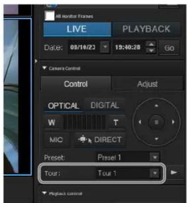
5 Press the shadow tour button.
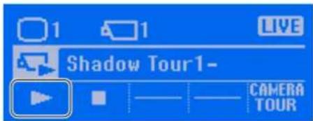
The shadow tour starts.
6 Press the button when you want to end the shadow tour.
Performing a Layout Tour
You can perform monitoring using the layout tour function for sequentially changing the display shown on the display at a preset time.
Note
To use the layout tour function, it needs to be set in advance. For the setting procedure, see the user's guide for your NSR-1000 series or RealShot Manager Advanced.
1 Select any monitor frame, and display the images of the camera you want to control.
2 Press the LAYOUT TOUR button.
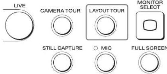
The Layout Tour screen appears.
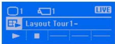
3 Select a layout tour.
To select with the numeric keypad:
Enter the layout tour number, and press the ENTER key.
To select with the joystick:
Select a layout tour from the [Tour] toolbar of the Main screen, and press the top button.
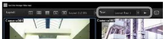

4 Press the button.
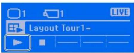
The layout tour starts.
5 Press the button when you want to end the layout tour.
The layout tour also ends when you press the TOP MENU button to redisplay the top screen.
Outputting Audio to the Camera
1 Select any monitor frame, and display the images of the camera to which you want to output audio.
2 Output audio by holding down the MIC button.
Audio is output to the camera while the MIC button is pressed.
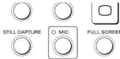
The LED is lit green while the button is pressed
Note
This function is only available with RealShot Manager Advanced.
Recording, Searching for, and Playing Back Images
You can record live images, and search for recorded image data or audio data and play back the data. It is also possible to export saved recorded images as files.
Perform image recording, searching, and playback operations from the Server menu of the multi function menu.
This section describes the following operations.
• Recording Live Images (page 29)
• Using the Jog/Shuttle Dial (page 30)
- Playing Back Recorded Images (page 31)
• Operations in the Search Screen (page 35)
• Searching for Recorded Images (page 36)
- Playing Back Recorded Images from Search Results (page 38)
Recording Live Images
You can record the images currently being captured by a camera.
Perform the recording operation from the multi function menu.
1 Select the monitor frame for which you want to record live images.

If live images are not displayed, press the LIVE button.
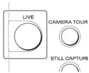
2 Press the button.
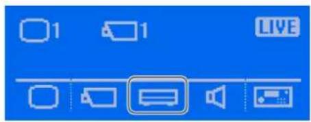
The Server menu screen appears.
3 Press the button.
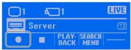
Recording starts.

Recording continues even if you change the layout.
4 Press the button when you want to stop recording.
Recording stops.
5 Press the TOP MENU button when you want to redisplay the top screen.
Using the Jog/Shuttle Dial
Use the jog/shuttle dial to change the playback speed and to frame-by-frame forward/rewind during the playback of recorded images.
The top part of the jog/shuttle dial is the jog dial, and the bottom part is the shuttle ring.
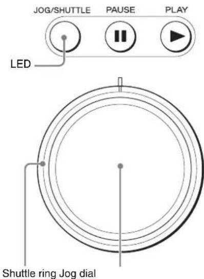
Note
The jog/shuttle dial can only be used when the JOG/SHUTTLE LED is lit. If the LED is not lit, press the JOG/SHUTTLE button to turn it on.
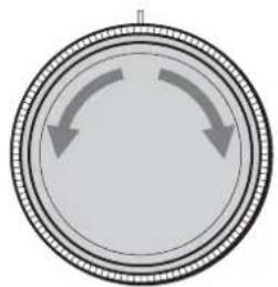
Using the jog dial
Use the jog dial to frame-by-frame forward/rewind recorded images.
Note
The jog dial can be used when the shuttle ring is in the center position.
natural_image
Circular diagram with two curved arrows pointing inward, no text or symbols presentRotate clockwise
Frame-by-frame forwarding is performed in accordance with the speed to which the jog dial is rotated.
Rotate counterclockwise
Frame-by-frame rewinding is performed in accordance with the speed to which the jog dial is rotated.
Using the shuttle ring
Use the shuttle ring to change the playback speed of recorded images.
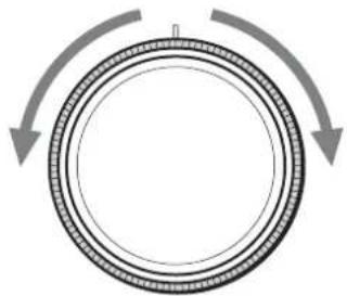
natural_image
Diagram of a circular mechanical component with two curved arrows indicating rotational motion (no text or symbols)Center
The recorded images are paused.
Rotate clockwise
The playback speed is changed in incremental steps as shown below
$$ \begin{array}{l} + 0. 2 x \longrightarrow + 1 x \longrightarrow + 2 x \longrightarrow + 5 x \longrightarrow + 1 0 x \longrightarrow + 2 0 x \longrightarrow \ + 5 0 x \end{array} $$
Rotate counterclockwise
The playback speed is changed in incremental steps as shown below
$$ - 0. 2 x \rightarrow - 1 x \rightarrow - 2 x \rightarrow - 5 x \rightarrow - 1 0 x \rightarrow - 2 0 x \rightarrow - 5 0 x $$
Playing Back Recorded Images
Simple operations are available for playing recorded images, including quick playback for automatically rewinding a specified amount of time before playback, using date and time to specify the amount of time to rewind or the playback position before playback, and playing from alarm history.
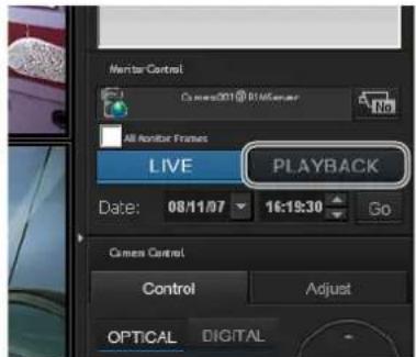
Quick Playback
By selecting a monitor frame and pressing the PLAY button during live status, you can automatically rewind the amount of time specified beforehand on the NSR-1000 series or RealShot Manager Advanced before playing back recorded images.
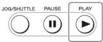
Note
You can configure the amount of time to rewind for quick playback on the GUI Configuration screen of the NSR-1000 series or RealShot Manager Advanced. For details, refer to the User's Guide (PDF) for the NSR-1000 series and RealShot Manager Advanced.
Specifying the amount of time to rewind (BEFORE TIME)
You can specify in minutes the amount of time to rewind before playback.
Note
This method for playback is unique to the system controller.
1 Select the monitor frame with the camera for which you want to play the recorded images assigned.
2 Press the button.
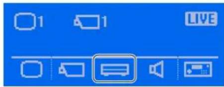
The Server menu screen appears.
3 Press the (PLAYBACK) button.
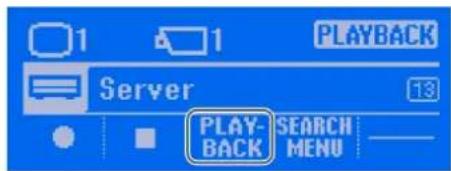
4 Press the (BEFORE TIME) button.
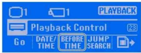
5 Enter the rewind time in minutes with the numeric keypad, and press the ENTER key.
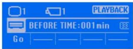
Note
The initial value for the rewind time is 1 minute.
The recorded images are found, and displayed in the monitoring frame in a paused state.
6 Press the (GO) button.
The recorded images are played back.
7 Press the TOP MENU button when you want to redisplay the top screen.
Specifying a date and time and then playing back recorded images
You can specify a date and time for the playback position of recorded images.
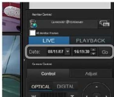
This operation corresponds to the action performed in the Monitor Control pane of the Main screen.
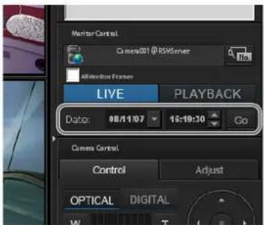
1 Select the monitor frame with the camera for which you want to play the recorded images assigned.
2 Press the button.
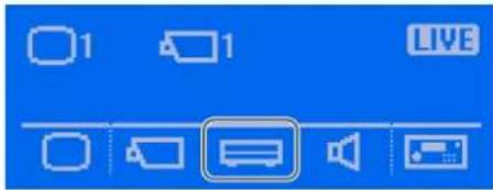
The Server menu screen appears.
3 Press the (PLAYBACK) button.
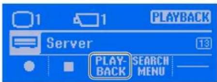
4 Press the (DATE/TIME) button.
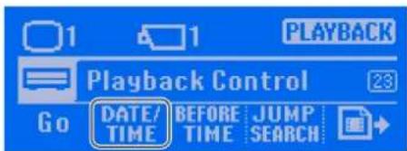
The screen for entering a date and time appears.
5 Enter the year/month/day with the numeric keypad, and press the ENTER key or (NEXT) button.
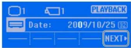
Note
The order in which the year, month, and day is displayed varies depending on the connected NSR-1000 series or RealShot Manager Advanced settings.
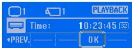
6 Enter the hour:minute:second with the numeric keypad, and press the ENTER key or (OK) button.
Note
Pressing the (PREV.) button redisplays the previous screen where you can specify a different date.
The specified date and time is reflected in [Date] of the [Monitor Control] pane.
7 Press the (GO) button.
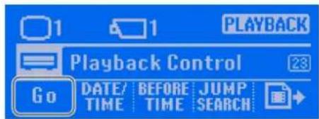
The recorded images are played back.
8 Press the TOP MENU button when you want to redisplay the top screen.
Jumping to recorded images for playback
You can search while jumping to recorded images one by one.
1 Select a monitor frame in which recorded images are being played back.
2 Press the button.
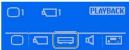
The Server menu screen appears.
3 Press the (PLAYBACK) button.
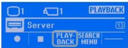
4 Press the (JUMP SEARCH) button.
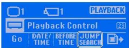
5 Press the desired button to search for images.
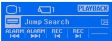
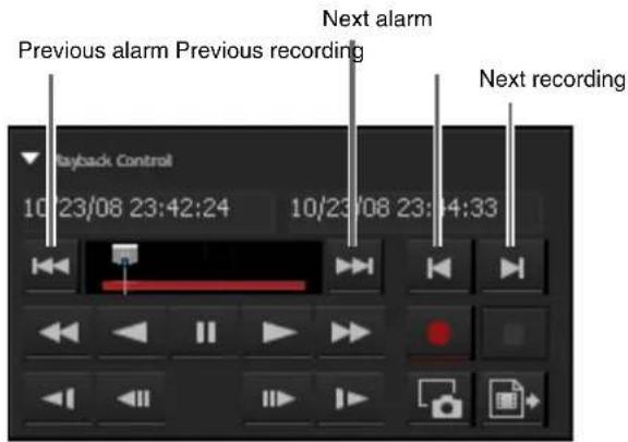
(Previous alarm): Search for the previous alarm recorded data.
ALARM (Next alarm): Search for the next alarm recorded data.
REC (Previous recoding): Search for the previous recording.
REC (Next recording): Search for the next recording.
The buttons correspond to the following buttons in the Playback Control pane.
6 Press the PLAY button.
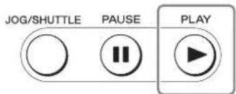
The recorded images are played back.
7 Press the TOP MENU button when you want to redisplay the top screen.
Playing back from alarm history
1 Click to select the monitor frame of the recorded images you want to play.
2 Press the ALARM button.
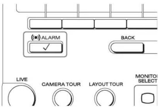
The following screen appears.
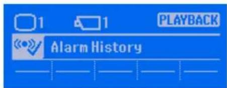

3 Use the joystick to select alarm history from the Alarm History pane, and press the top button.
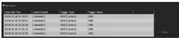
4 Press the TOP MENU button when you want to redisplay the top screen.
Operations in the Search Screen
The Search screen of the NSR-1000 series and RealShot Manager Advanced and the system controller are linked as shown below.
①Specifying search conditions ②Image control
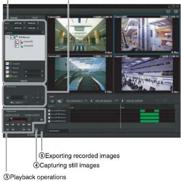
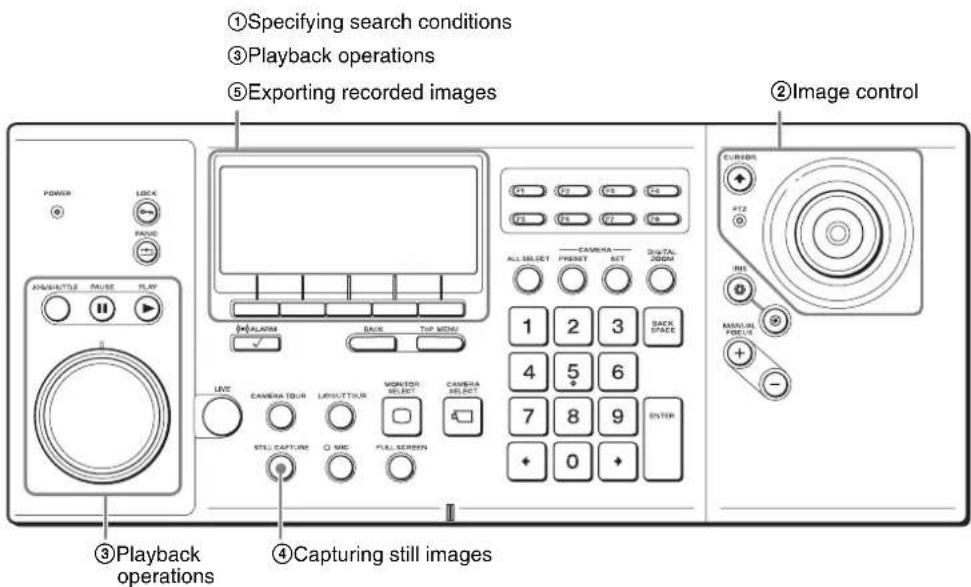
| Operation Reference | Page | |
| 1 | Specifying search conditions 36 | |
| 2 | Image control 21 | |
| 3 | Playback operations 31 | |
| 4 | Capturing still images 41 | |
| 5 | Exporting recorded images 38 |

Searching for Recorded Images
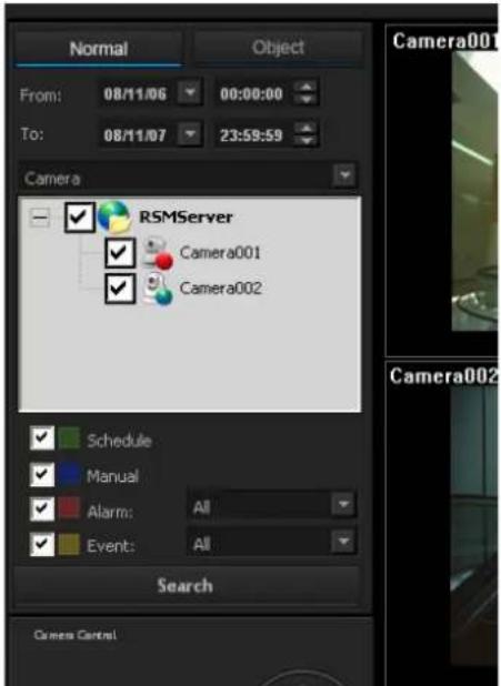
You can search for a recorded image from the previous day by searching all triggers, instead of specifying the date and time or the recording type. You can also specify advanced search conditions, as necessary.
This operation corresponds to the action performed on the [Normal] tab of the Search screen.
Note
The check box of the device selected in the Main screen is selected. When the [All monitor frames] check box is selected in the Main screen, the check boxes for all displayed devices are selected.
1 Press the button.
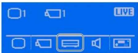
The Server menu screen appears.
2 Press the (SEARCH MENU) button.
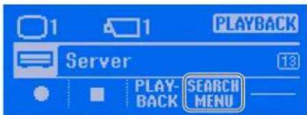
Note
Pressing the (SEARCH MENU) button switches from the Main screen to the Search screen.
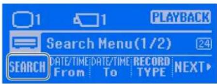
3 Press the (SEARCH) button.
By pressing the 5(SEARCH) button without specifying a time, you can search all trigger conditions within the previous 24 hours of images from the selected camera.
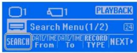
A list of search results is displayed.
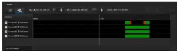
Note
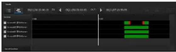
When you perform search operations using the system controller, search results are displayed in timeline view.
Specifying Advanced Search Conditions
1 Specify a range of dates and times for which to search.
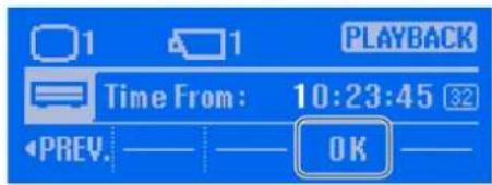
①Specify the search start point. Click the (DATE/TIME FROM) button.
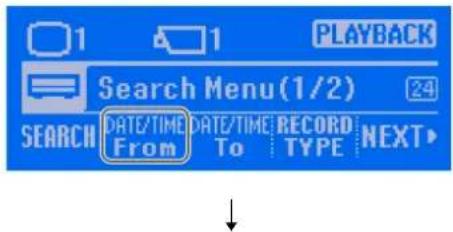
Enter the year/month/day with the numeric keypad, press the ENTER key or (NEXT) button.
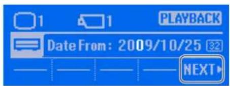
Note
The order in which the year, month, and day is displayed varies depending on the connected NSR-1000 series or RealShot Manager Advanced settings.

Enter the hour:minute:second with the numeric keypad, and press the ENTER key or (OK) button.
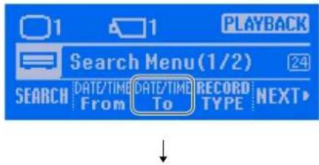
②Specify the search end point. Click the (DATE/TIME TO) button.
Enter the year/month/day with the numeric keypad, and press the ENTER key or (NEXT) button.
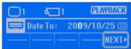
Note
The order in which the year, month, and day is displayed varies depending on the connected NSR-1000 series or RealShot Manager Advanced settings.

Enter the hour:minute:second with the numeric keypad, and press the ENTER key or (OK) button.
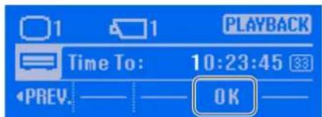
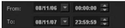
The Search Menu (1/2) screen is redisplayed.
The specified dates and times are reflected in [From] and [To].
2 Specify the recording types for which to search.
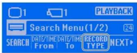
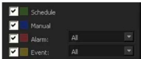
①Press the (RECORD TYPE) button.
②Press the recording type buttons. A button is switched on or off each time it is pressed.
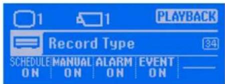
The corresponding checkmarks in the Search screen also turn on or off because they are linked to the buttons.
Notes
- Pressing the BACK button redispplays the previous screen where you can specify search conditions again.
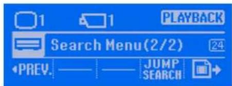
- Pressing the (NEXT) button in step (1) displays the following screen, and you can perform a search (JUMP SEARCH) or export recorded images.
3 Press the (SEARCH) button to start the search.
A list of search results is displayed.
Note
When you perform search operations using the system controller, search results are displayed in timeline view.
4 Press the TOP MENU button when you want to redisplay the top screen.
Playing Back Recorded Images from Search Results
Press the PLAY button.
The recorded images are played back in the selected monitor frame.
Exporting Recorded Images
This function can be performed in both the Main screen and the Search screen.
Video is exported in a native format (.cam file), and still images in JPEG format. Exported video can be played back with an application for playing CAM files.
Exporting Recorded Images
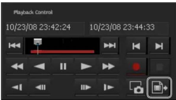
You can export saved recorded images as files. The start point (mark in) and end point (mark out) of the recorded images to export can be specified during playback, as well as by specifying dates and times.
Notes
- When using the NSR-1000 series, the images are exported to USB media.
- When using RealShot Manager Advanced, the images are exported to the hard disk.
Export destination: Install folder\Exports
• Media File Player is exported with the images.
This operation corresponds to the operation for exporting recorded images in the Playback Control pane of the Main screen and Search screen.
Displaying the Export Screen
Export recorded images in the Export screen of the Server menu.
1 Select a monitor frame, and display the recorded images you want to export.
2 Press the button.
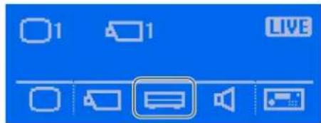
The Server menu screen appears.
3 Press the (PLAYBACK) button.
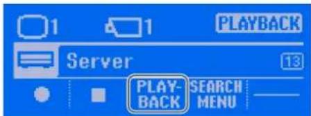
4 Press the button.
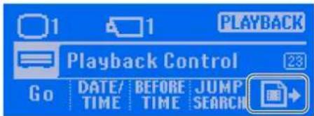
The Export screen appears.
Specifying the start point and end point during playback
1 Play back the recorded images, press the button.
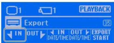
The start point is set for the current position.
2 Play back the recorded images, press the (OUT) button.
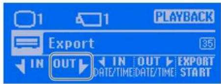
The end point is set for the current position.
3 Press the (EXPORT START) button.
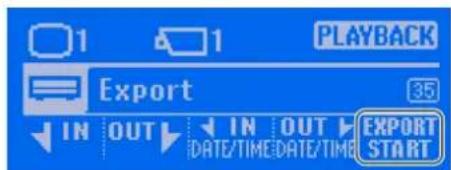
The recorded images and Media File Player are exported to the USB media.
4 Press the TOP MENU button when you want to redisplay the top screen.
Specifying dates and times for the start point and end point
1 Display the Export screen, and press the (IN DATE/TIME) button.
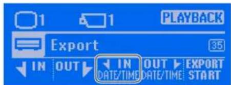
2 Specify the date and time for the start point.
①Enter the year/month/day with the numeric keypad, and press the ENTER key or (NEXT) button.
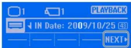
Note
The order in which the year, month, and day is displayed varies depending on the connected NSR-1000 series or RealShot Manager Advanced settings.
②Enter the hour:minute:second with the numeric keypad, and press the ENTER key or (OK) button.
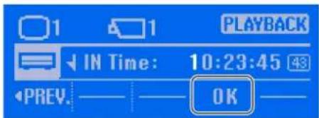
The start point is set.
3 Specify the date and time for the end point.
①Enter the year/month/day with the numeric keypad, and press the ENTER key or (NEXT) button.
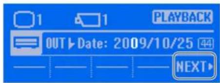
Note
The order in which the year, month, and day is displayed varies depending on the connected NSR-1000 series or RealShot Manager Advanced settings.
②Enter the hour:minute:second with the numeric keypad, and press the ENTER key or (OK) button.
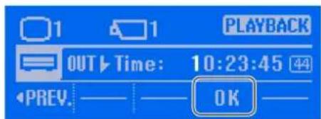
The end point is set, and the Export screen is redisplayed.
4 Press the (EXPORT START) button.
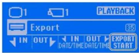
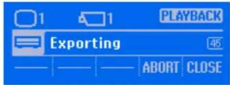
Export begins and the exporting in progress screen appears.
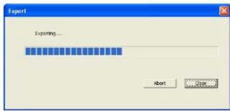
The following screen also appears on the NSR-1000 series and RealShot Manager Advanced to display the progress.
Notes
- If there is insufficient free space on the media, exporting stops.
- If you click (CLOSE) during exporting, you can return to the Main screen while continuing exporting.
- If you click (ABORT), the export ends partway through, but the recorded images up until that point are exported.
- If files that are currently recording are exported, they may not be able to be played back normally. When exporting recordings that are currently recording, specify an end point (mark out) that is well beyond the current time.
5 Press the TOP MENU button when you want to redisplay the top screen.
Exporting Recorded Images as Still Images
You can capture one scene of recorded or live images and export it as a still image file.
Note
Captured still images are stored on USB media with the NSR-1000 series, and on the hard disk with RealShot Manager Advanced.
Export destination: Install folder\Snapshots
This operation corresponds to the operation for capturing still images in the Playback Control pane of the Main screen and Search screen.
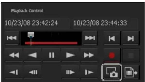
1 Select any monitor frame, and display the images of the camera you want to control.
2 Press the STILL CAPTURE button.
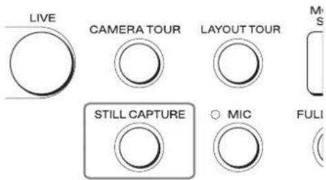
The still image file is exported.
Locking Operation
When, for instance, you leave your seat during operation, you can lock system controller operation to prevent other people performing operations.
To Lock Operation
Press the LOCK button.
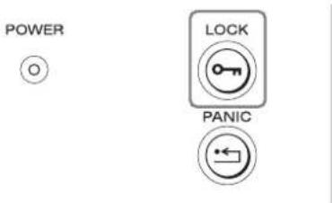
The following screen appears, and the lock is set.
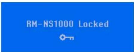
Note
Pressing the LOCK button for at least 3 seconds switches to the off state. For details, see "Setting the System Controller to the Off State" (page 42).
To Unlock the Lock
1 Press the LOCK button.
POWER


If a password is not set, the top screen appears. If a password is set, a screen requesting you to enter the password appears.
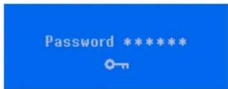
2 Enter the password with the numeric keypad, and press the ENTER key.
If the password is authenticated, the top screen appears.
Setting the System Controller to the Off State
Pressing the LOCK button for at least 3 seconds sets the system controller to the off state.
POWER


You can also set the system controller to automatically enter the off state when no operation is performed for a set amount of time (the default setting is OFF). You can set the time until the system controller enters the off state in the multi function menu. For details, see "System Lock" (page 48).
To recover from the off state
The operating procedure is the same as that for unlocking the lock. See "To Unlock the Lock" (page 42).
Adjusting the Brightness of the LCD
You can adjust the backlight brightness and contrast of the LCD. It is also possible to turn on or off the code number indication.
Adjusting the Brightness and Contrast
1 Press the button.
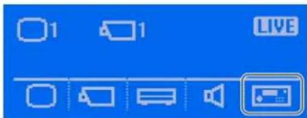
The Controller menu screen appears.
2 Press the (LCD) button.
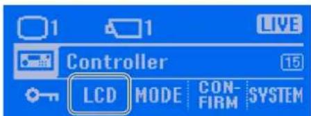
The LCD screen appears.
3 Press the button to adjust the backlight brightness, and press the button to adjust the contrast.
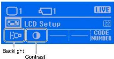
4 Press the or button to adjust the brightness.
Example: When adjusting the backlight
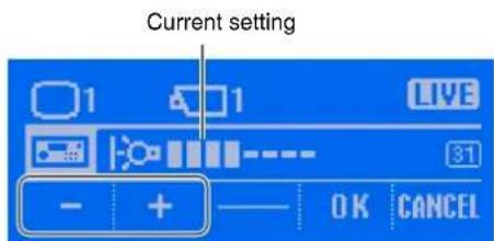
The contrast can be adjusted in the same way.
5 Press the (OK) button.
The LCD menu screen is redisplayed.
6 Press the TOP MENU button to redisplay the top screen.
Turning On/Off the code number indication
Code numbers are numbers to help you for refer to this guide. You can turn on or off the indication.
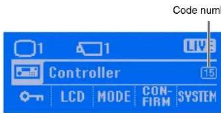
Note
For how to use code numbers, see "Screen Index" (page 63).
1 Press the button.
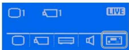
The Controller menu screen appears.
2 Press the (LCD) button.
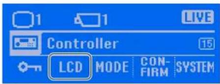
The LCD screen appears.
3 Press the (CODE NUMBER) button.
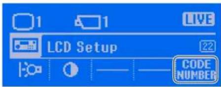
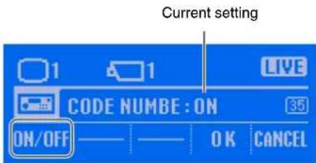
4 Press the ON/OFF button.
Each press turns the item on or off.
5 Press the TOP MENU button to redisplay the top screen.
Multi Function Menu
The multi function menu of RM-NS1000 mode contains the following menu items.
| Menu Item Description | Option Reference | Page | |
| Monitor Layout Allows you to change the layout. | 45 | ||
| Device Allows you to turn backlight compensation on or off, set the day/night function, perform a manual action, and set a shadow tour. | 45 | ||
| Server Allows you to perform operations such as recording live images, specifying the date and time for playback, controlling playback, searching and playing back, and exporting recorded images. | 29 | ||
| Volume Allows you to adjust the volume of the audio input from the camera. | 47 | ||
| Controller | |||
| System Lock Allows you to set or change the system controller password and set the time until the system controller enters the off state. | 48 | ||
| LCD Allows you to adjust the backlight brightness and contrast of the LCD display. | 43 | ||
| MODE Allows you to switch to RM-NS1000 mode or Pelco mode. | 15 | ||
| Button Confirmation | Allows you to enable or disable the PANIC button, and set whether to display a confirmation screen when the function buttons are pressed. | 50 | |
| System Menu | Allows you to view version information for the system software. | 51 | |
Monitor Layout
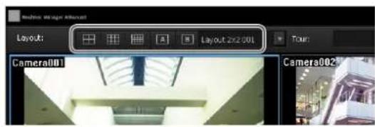
You can change the layout in the Monitor Layout menu. This operation corresponds to the operation for selecting a layout on the Layout toolbar.
1 Press the button.
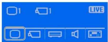
The Monitor Layout screen appears.
2 Press the button for the layout to which you want to change.
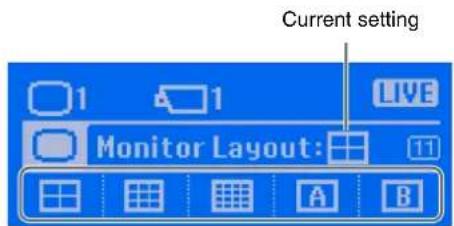
The layout is changed.
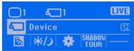
Device
You can turn backlight compensation on or off, set the day/night function, enable or disable the alarm output connector, and perform a manual action.
Displaying the Camera Setup menu
1 Select the camera you want to set.
2 Press the button.
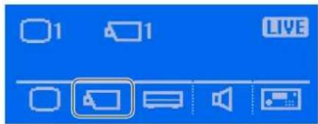
The Device screen appears.
Backlight compensation (BLC)
If the camera has a BLC function, you can turn backlight compensation on or off.
1 Press the button in the Device screen.
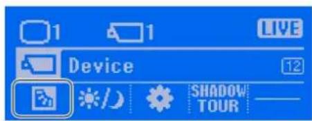
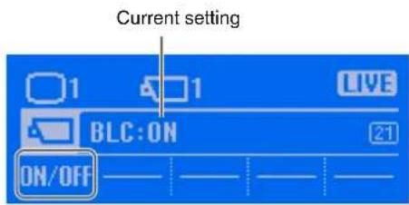
The BLC screen appears.
Each press turns the item on or off.
Day/Night function (Day/Night)
Set this function if the camera has a day/night function.
1 Press the button in the Device screen.
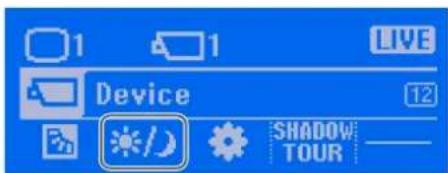
The Day/Night screen appears.
2 Press the button for the desired setting.
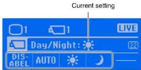
DIS- : Disable
AUTO: Auto adjustment
: Day mode
: Night mode
The setting is changed.
Manual actions (Manual Action)
You can perform a manual action. This operation corresponds to the operation for selecting a manual action in the Manual Action pane.
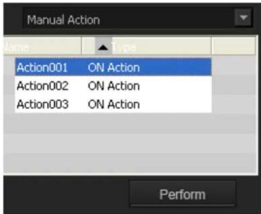
1 Press the button in the Camera Setup screen.
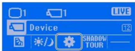
The MANUAL ACTION screen appears.
2 Enter the number of the manual action you want to perform with the numeric keypad, and press the ENTER key.
You can also use the joystick to select from the Manual Action pane.
3 Press the (PERFORM) button.
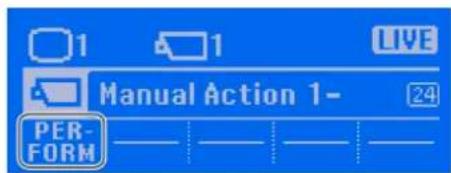
The manual action is performed.
Shadow tours (Shadow Tour)
If the camera has a shadow tour function, you can record the pan, tilt, and zoom movements of a camera, and register them as a shadow tour.
For details on performing a registered shadow tour, see "Performing Shadow Tours" (page 26).
1 Press the (SHADOW TOUR) button in the Device screen.
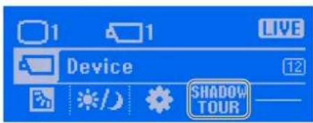
The Shadow Tour screen appears.
2 Enter the shadow tour number you want to register with the numeric keypad, and press the ENTER key.
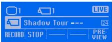
3 Press the (RECORD) button to start recording your operations.
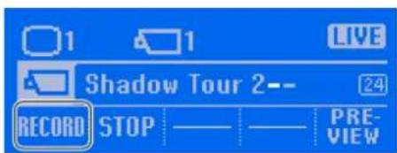
Recording begins.
4 Perform pan, tilt, and zoom operations.
5 Press the (STOP) button when you want to stop recording.
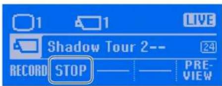
Recording stops.
Notes
- Recording time limits vary depending on camera specifications.
- When the recording time limit for a camera is reached, recording will stop before you press the STOP (STOP) button.
6 Press the (PREVIEW) button to confirm your recorded operations.
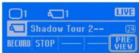
The recorded operations are performed.
Volume
You can adjust the volume of external outputs from the headphone jack on the system controller.
1 Press the button.
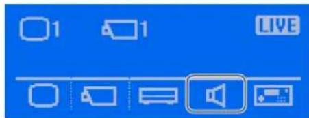
The setting screen appears.
2 Press the button for the desired setting.
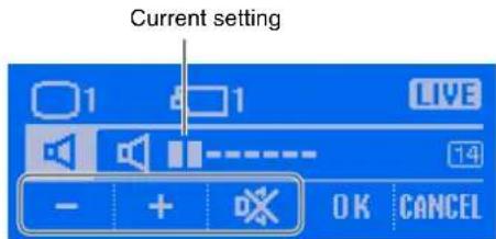
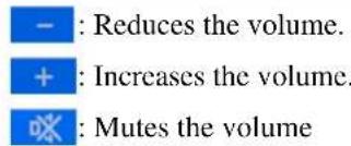
3 Press the (OK) button.
System Lock
You can set or change the system controller password, and set the function that automatically sets the system controller to the off state when no operation is performed for a set amount of time (the default setting is OFF).
Displaying the System Lock menu
1 Press the button.
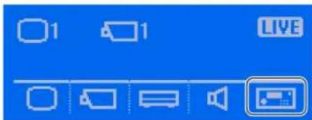
The Controller screen appears.
2 Press the button.
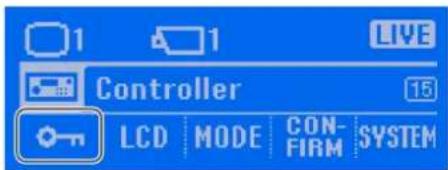
The System Lock screen appears.
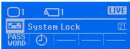
Setting the password
Set the system controller password.
The default password setting is "111111."
1 Press the (PASSWORD) button in the System Lock screen.
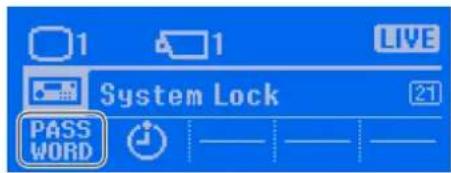
The Password screen appears.
2 Press the ON/OFF button.
Each press turns the item on or off.
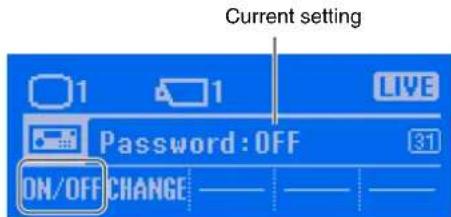
The screen for entering a password appears.
3 Enter the password with the numeric keypad, and press the ENTER key.
Set 6 characters for the password.
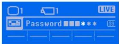
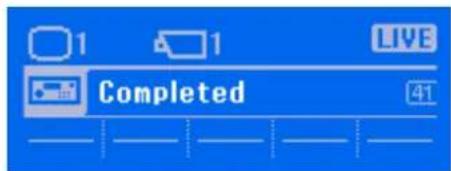
If the password setting is successful, the following screen appears.
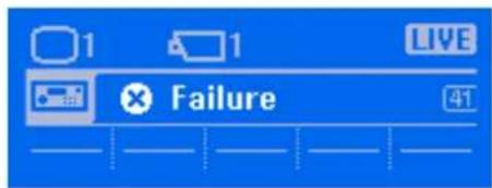
Note
If an invalid password was entered, the following screen appears. Enter another password.
The password is set.
Changing the password
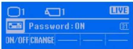
1 Press the (PASSWORD) button in the System Lock screen.
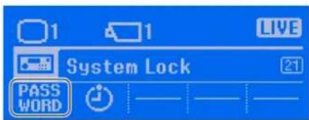
The Password screen appears.
2 Press the (CHANGE) button.
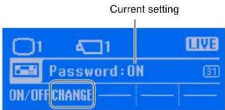
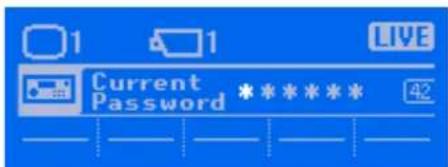
A screen for entering the current password appears.
3 Enter the current password with the numeric keypad, and press the ENTER key.
A screen for entering a new password appears.
4 Enter the new password with the numeric keypad, and press the ENTER key.
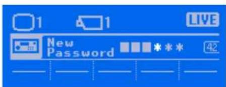
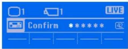
5 Enter the same password for confirmation with the numeric keypad, and press the ENTER key.
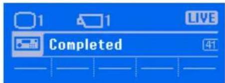
If setting the password is successful, the following screen appears, and the System Lock screen is redisplayed after 3 seconds.
Setting the time until the system controller enters the off state
Set the time (timer) until the system controller automatically enters the off state when no operation is performed for a set time. You can also turn off the timer.
1 Press the button in the System Lock screen.
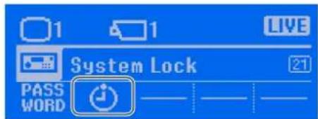
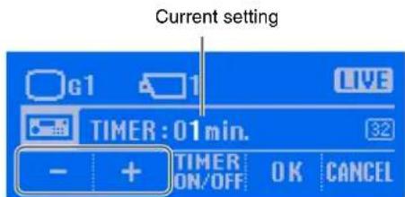
The TIMER screen appears.
2 Press the or button to set the time.
You can set from 1 to 30 minutes. The initial value is 5 minutes.
Note
To turn the timer off, press the button. Each press turns the item on or off.
3 Press the (OK) button.
When the time is set, the System Lock screen is redisplayed.
Button Confirmation
You can set whether to display a confirmation screen when the PANIC button or custom function buttons are pressed.
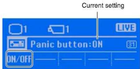
Selecting whether to display a confirmation screen when the PANIC button is pressed
1 Press the button.
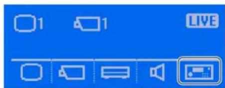
The Controller screen appears.
2 Press the (CONFIRM) button.
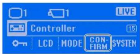
The Button Confirmation screen appears.
3 Press the (PANIC) button.
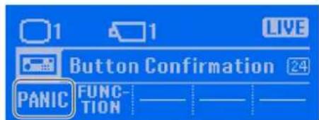
Each press turns the item on or off.
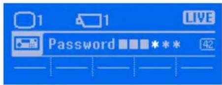
If a password is set, a screen requesting you to enter the password appears. Go to step 5. If a password is not set, a confirmation screen appears. Go to step 6.
5 Enter the password with the numeric keypad, and press the ENTER key.
If the password is authenticated, a confirmation screen appears.
6 Press the (OK) button.
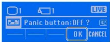
When the setting is finished, the Button Confirmation screen is redisplayed.
Selecting whether to display a confirmation screen when the custom function buttons are pressed
When this function is enabled, a confirmation screen will appear when you press the F1 to F3 buttons, allowing you to confirm whether to perform the operation.
1 Press the button.
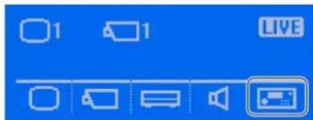
The Controller screen appears.
2 Press the (CONFIRM) button.
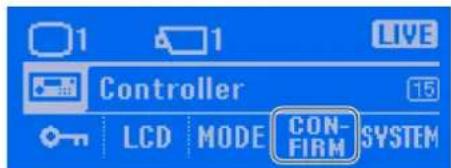
The Button Confirmation screen appears.
3 Press the (FUNCTION) button.
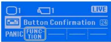
Each press turns the item on or off.
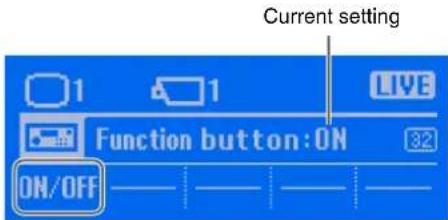
5 Press the (OK) button.
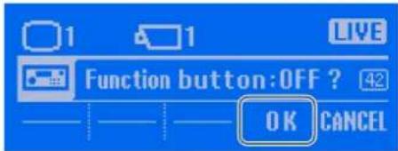
When the setting is finished, the Button Confirmation screen is redisplayed.
System Menu
You can view version information for the system software.
Displaying the System Menu
1 Press the button.
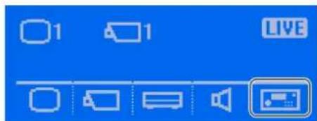
The Controller screen appears.
2 Press the SYSTEM) button.
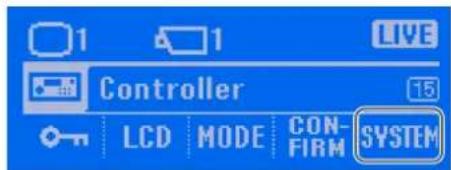
The System Menu screen appears.
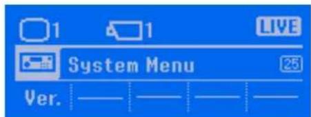
Viewing the version information
1 Press the (Ver.) button.
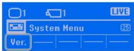
The version information appears.
2 Press the (OK) button.
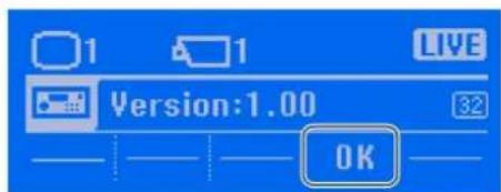
The System Menu is redisplayed.
Operations in Pelco Mode
Chapter
3
Overview
This mode is used for performing pan, tilt, and zoom controls for Pelco-D or -P protocol cameras connected directly to the system controller via the RS-485 port.
This chapter describes the following operations in Pelco mode.
• Viewing and Using the LCD (page 52)
- Switching Modes (page 53)
- Selecting a Camera (page 54)
• Controlling Cameras (page 55)
- Locking Operation (page 56)
- Setting the System Controller to the Off State (page 57)
- Adjusting the Brightness of the LCD (page 57)
- Multi Function Menu (page 58)
Note
For details on the RS-485 pin arrangement, see "I/O Port" (page 70).
Viewing and Using the LCD
On the LCD, you can check the current status and operate the multi function menu.
Viewing the LCD
Top screen
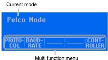
When you have entered the multi function menu
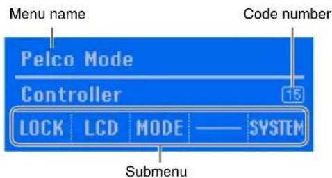
Note
Code numbers are numbers to help you refer to this guide. For details on how to use code numbers, see "Screen Index" (page 63).
Operating the Multi Function Menu
Each item of the multi function menu corresponds to one of the multi function buttons below the LCD.
When you want to select or operate an item of the multi function menu, press the button directly below the item to display a screen that corresponds with that item.
Example: When operating the menu
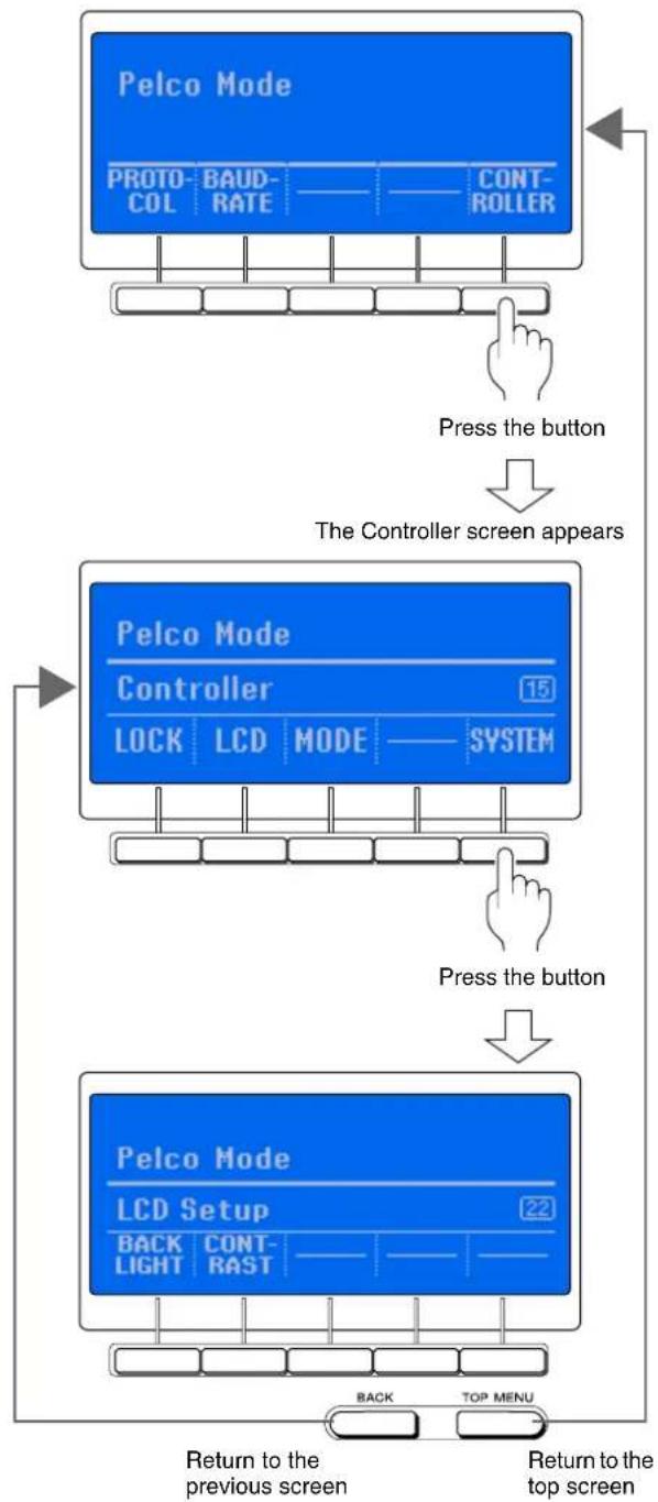
flowchart
graph TD
    A["Pelco Mode\nPROTO-COL BAUD-RATE CONTROLLER"] --> B["Press the button"]
    B --> C["The Controller screen appears"]
    C --> D["Pelco Mode\nController\nLOCK LCD MODE SYSTEM 15"]
    D --> E["Press the button"]
    E --> F["Pelco Mode\nLCD Setup\nBACK LIGHT CONT-RAST 22"]
    F --> G["Return to the previous screen"]
    F --> H["Return to the top screen"]
    G --> I["Back TOP MENU"]
Switching Modes
Switch to RM-NS1000 mode or Pelco mode in accordance with the devices you are using.
1 Press the (MODE) button.
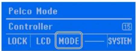
The Mode screen appears.
2 Press the button for the mode to which you want to switch.
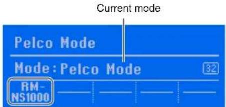
If a password is set, a screen requesting you to enter the password appears. Go to step 3.
If a password is not set, a confirmation screen appears. Go to step 4.
3 Enter the password with the numeric keypad, and press the ENTER key.
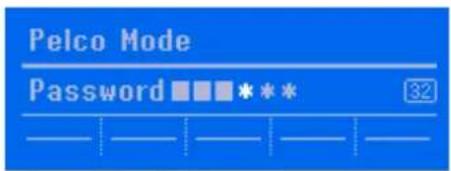
If the password is authenticated, a confirmation screen appears.
4 Press the (OK) button.
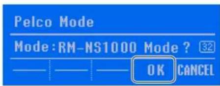
The setting complete screen appears, and the flashing "Completed" indication appears.
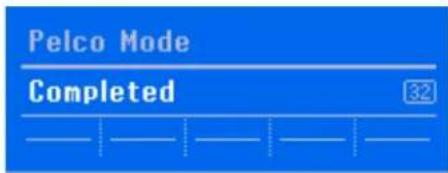
The mode is switched, and the top screen of the selected mode appears.
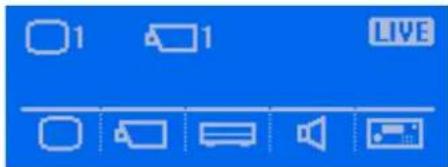
Selecting a Camera
Select the camera for which to perform pan, tilt, and zoom control.
1 Select the monitor frame in which to display the camera images.
2 Press the (CAMERA SELECT) button.
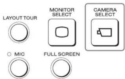
The following screen appears.
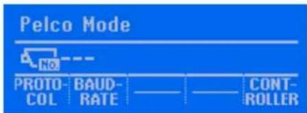
3 Enter the camera ID with the numeric keypad, and press the ENTER key.
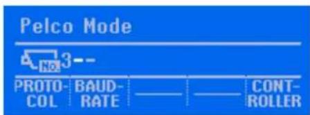
The images of the selected camera appear in the monitor frame, and the selected camera ID appears in the screen on the LCD.
Example: When camera 003 is selected

Controlling Cameras
For a camera equipped with pan and tilt functions, you can monitor the images from the camera while performing operations such as panning, tilting, and zooming.
Note
The PTZ LED on the system controller lights green when pan, tilt, and zoom operations can be performed.
Performing Pan, Tilt, and Zoom Operations
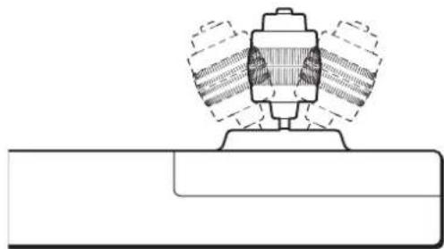
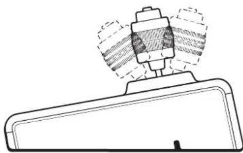
The panning and tilting operations are achieved by moving the joystick in the direction in which you want the camera to face.
Panning
Move the joystick right or left.
Front view
natural_image
Technical line drawing of a mechanical assembly with no visible text or symbolsTilting
Move the joystick up or down.
Right view
natural_image
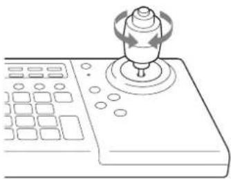
Technical line drawing of a mechanical component with no visible text or symbolsZooming
Rotate the joystick clockwise to zoom in (Tele), and rotate it counterclockwise to zoom out (Wide).
natural_image
Line drawing of a joystick controller with control panel and scroll wheel (no text or symbols)Using Manual Focus
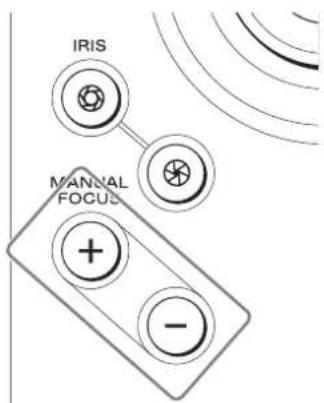
You can use the MANUAL FOCUS button to adjust the focus manually.
Press when you want to focus on an object in the distance and press when you want to focus on an object nearby.
Adjusting the Brightness of Images
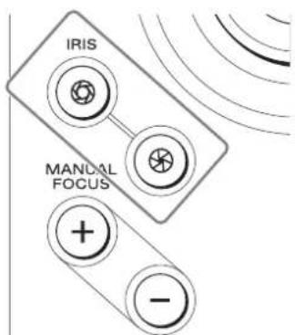
Adjust the iris of the camera to change the brightness. Adjust the aperture in the direction to make the images brighter, and adjust it in the direction to make the images darker.
Locking Operation
When, for instance, you leave your seat during operation, you can lock system controller operation to prevent other people performing operations.
To Lock Operation
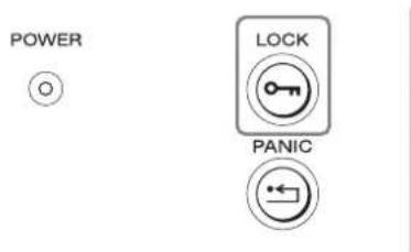
Press the LOCK button.
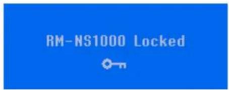
The following screen appears, and the lock is set.
Note
Pressing the LOCK button for at least 3 seconds switches to the off state. For details, see "Setting the System Controller to the Off State" (page 57).
To Unlock the Lock
1 Press the LOCK button.
POWER

If a password is not set, the top screen appears. If a password is set, a screen requesting you to enter the password appears.
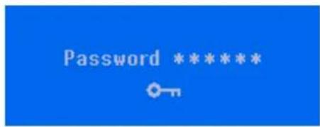
2 Enter the password with the numeric keypad, and press the ENTER key.
If the password is authenticated, the top screen appears.
Setting the System Controller to the Off State
Pressing the LOCK button for at least 3 seconds sets the system controller to the off state.

The system controller also enters the off state automatically if no operation is performed for the set time or longer. You can set the time until the system controller enters the off state in the multi function menu. For details, see "System Lock" (page 60).
To recover from the off state
The operating procedure is the same as that for unlocking the lock. See "To Unlock the Lock" (page 56).
Adjusting the Brightness of the LCD
Allows you to adjust the backlight brightness and contrast of the LCD display.
1 Press the button.
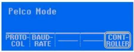
The Controller menu screen appears.
2 Press the (LCD) button.
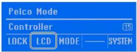
The Controller menu screen appears.
3 Press the (BACK LIGHT) button to adjust the backlight brightness, and press the CONTRAST (CONTRAST) button to adjust the contrast.
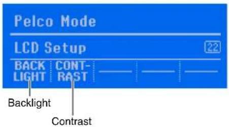
4 Press the or button to adjust the brightness.
Example: When adjusting the backlight
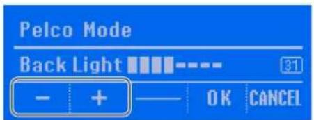
The contrast can be adjusted in the same way.
5 Press the (OK) button.
The LCD menu screen is redisplayed.
6 Press the TOP MENU button to redisplay the top screen.
5
Press the (OK) button.
Multi Function Menu
The multi function menu of Pelco mode contains the following menu items.
| Menu Item Description | tion Reference | Page | |
| Protocol Sets the control protocol. 59 | |||
| Baudrate Set the baud rate. 59 | |||
| Controller | |||
| System Lock Allows you to lock or unlock the system, set or change the system controller password, and set the time until the system controller enters the off state. | 56 | ||
| LCD Allows you to adjust the backlight brightness and contrast of the LCD display. | 57 | ||
| MODE Allows you to switch to RM-NS1000 mode or Pelco mode. | 53 | ||
| System Menu Allows you to view version information for the system software. | 62 | ||
Protocol
Set the control protocol for Pelco-D or P protocol cameras in the Protocol menu.
1 Press the (PROTOCOL) button.
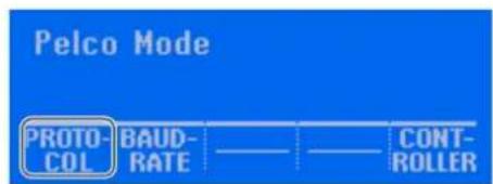
The Protocol screen appears.
2 Press the (Pelco-D/P) button.
Each press switches between [Pelco-D] and [Pelco-P].
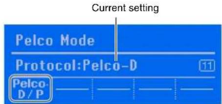
A confirmation screen appears.
3 Press the (OK) button.
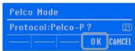
The control protocol is set.
Baudrate
Set the baud rate.
1 Select the camera you want to set.
2 Press the button.
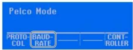
The Baudrate screen appears.
3 Press the button for the baud rate you want to set.
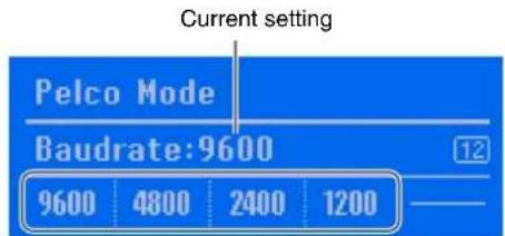
A confirmation screen appears.
4 Press the (OK) button.
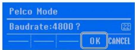
The baud rate is set.
System Lock
You can lock or unlock the system, set or change the system controller password, and set the time until the system controller automatically enters the off state when no operation is performed for a set amount time.
Displaying the System Lock menu
1 Press the button.
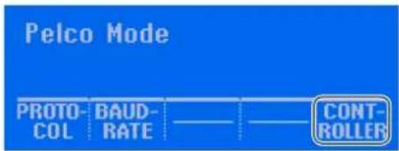
The Controller screen appears.
The System Lock screen appears.
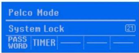
Setting the password
Set the system controller password. The default password setting is "111111."
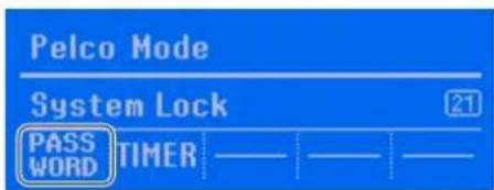
1 Press the (PASSWORD) button in the System Lock screen.
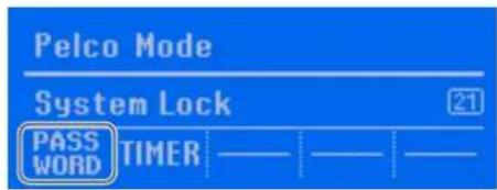
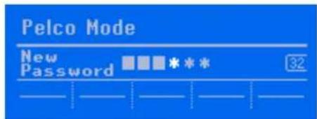
A screen for entering a new password appears.
2 Enter the password with the numeric keypad, and press the ENTER key.
Set 6 characters for the password.
Note
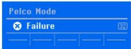
If an invalid password was entered, the following screen appears. Enter another password.
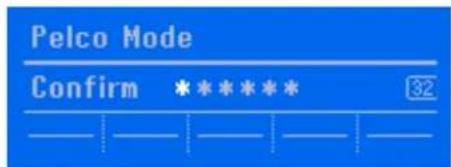
3 Enter the same password for confirmation with the numeric keypad, and press the ENTER key.
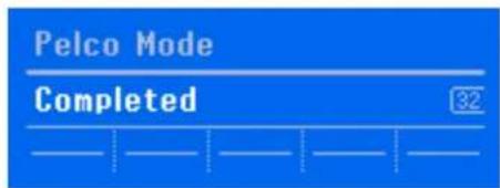
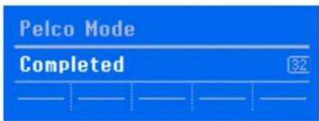
If setting the password is successful, the following screen appears, and the System Lock screen is redisplayed.
Changing the password
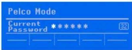
1 Press the (PASSWORD) button in the System Lock screen.
A screen for entering the current password appears.
2 Enter the current password with the numeric keypad, and press the ENTER key.
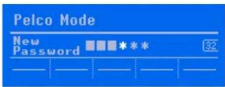
A screen for entering a new password appears.
3 Enter the new password with the numeric keypad, and press the ENTER key.
4 Enter the same password for confirmation with the numeric keypad, and press the ENTER key.
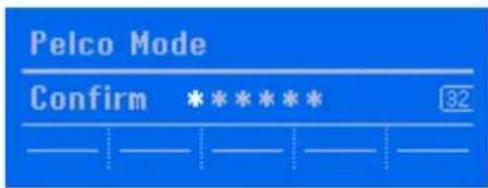
If setting the password is successful, the following screen appears, and the System Lock screen is redisplayed.
Setting the time until the system controller enters the off state
Set the time (timer) until the system controller automatically enters the off state when no operation is performed for a set time. You can also turn off the timer.
1 Press the (TIMER) button in the System Lock screen.
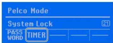
The TIMER screen appears.
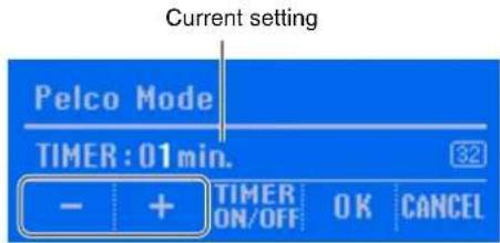
2 Press the or button to set the time.
You can set from 1 to 30 minutes. The initial value is 5 minutes.
Note
To turn the timer off, press the button. Each press turns the item on or off.
3 Press the (OK) button.
When the time is set, the System Lock screen is redisplayed.
System Menu
You can view version information for the system software.
Displaying the System Menu
1 Press the button.
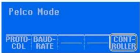
The Controller screen appears.
2 Press the SYSTEM button.
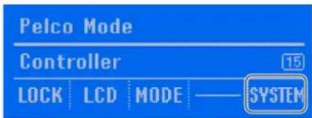
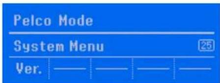
The System Menu screen appears.
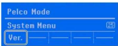
Viewing the version information
1 Press the (Ver.) button.
The version information appears.
2 Press the (OK) button.
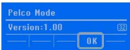
The System Menu is redisplayed.
Other Information
Chapter
4
Screen Index
If you do not know how to perform an operation, you can use the code number displayed on the right side of the screen to find the page for the operation in this user's guide.
RM-NS1000 Mode
| Code Number | Screen Refer- | ence Page |
11 Layout selection 45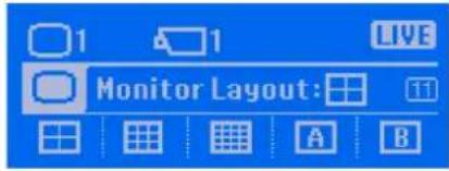 | ||
12 Device menu 45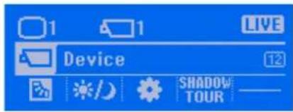 | ||
13 Server menu 29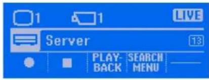 |
| Code Number | Screen Refer- | ence Page |
| 14 Volume adjustment for headphone jack output | 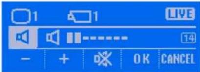 | 47 |
| 15 Controller menu 14 | 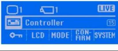 |

| Code Number | Screen Refer- | ence Page |
21 Enable/disable backlight compensation function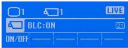 | 45 | |
21 System lock menu 48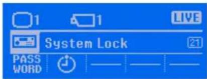 | ||
22 LCD adjustment 43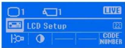 | ||
22 Day/night function setting 46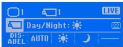 | ||
23 Mode selection 15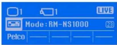 | ||
23 Playback control menu 31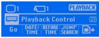 | ||
| Code Number | Screen Refer- | ence Page |
| 24 Search menu 36 | 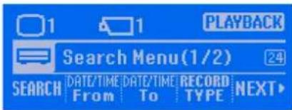 | |
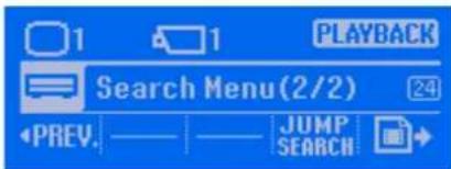 | ||
| 24 Perform manual action 46 | 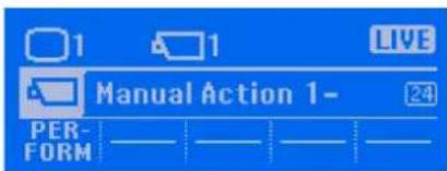 | |
| 24 Shadow tour registration 47 | 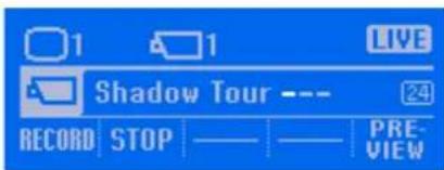 | |
| 24 Shadow tour recording 47 | 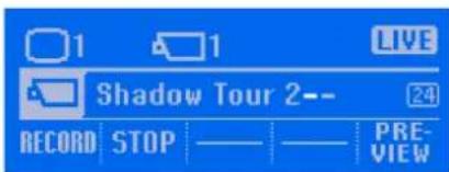 | |
| 24 Enable/disable confirmation screen display | 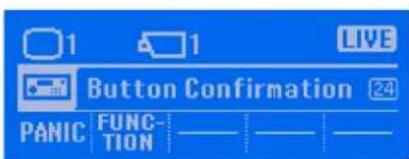 | 50 |
| 25 System menu 51 | 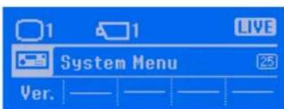 | |
31 LCD brightness (backlight) adjustment 43 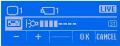 | ||
31 Password setting/changing 48 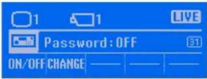 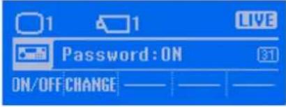 | ||
31 Enable/disable confirmation screen display when the PANIC button is pressed 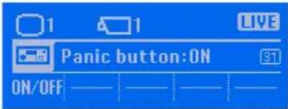 | 50 | |
32 LCD contrast adjustment 43 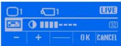 | ||
32 Date entry 32 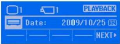 | ||
32 Time entry 32 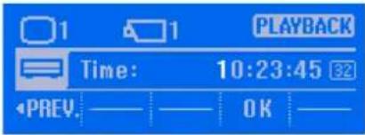 | ||
| Code Number | Screen Refer- | ence Page |
| 32 Start point specification(year / month / day) | 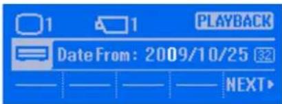 | 36 |
| 32 Start point specification(hour : minute : second) | 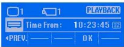 | 37 |
| 32 Off state timer setting (duration before off state) | 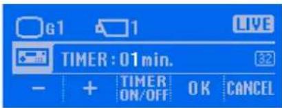 | 49 |
| 32 Enable/disable confirmation screen display when the custom function buttons are pressed | 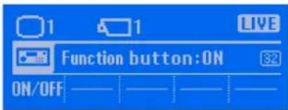 | 51 |
| 32 Version information 51 | 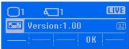 | |
| 33 Password entry 15, 48 | 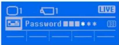 | |
| 33 Mode selection confirmation 15 | 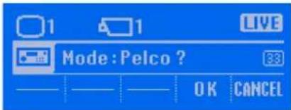 | |
33 Time specification for rewind playback 31 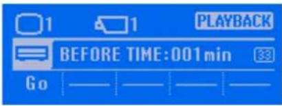 | ||
33 End point specification (year / month / day) 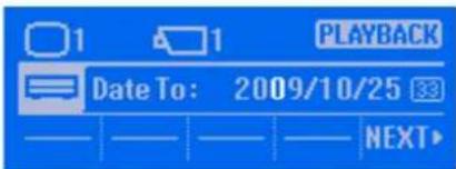 | 37 | |
33 End point specification (hour : minute : second) 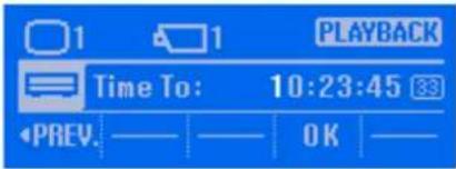 | 37 | |
34 Jumping to recorded images 33 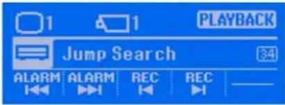 | ||
34 Recording type selection 37 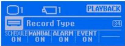 | ||
35 Export menu for recorded images 39 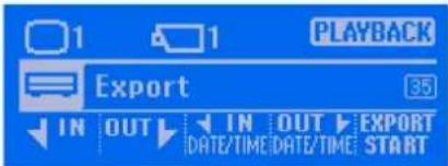 | ||
35 Enable/disable code number display 44 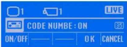 | ||
| Code Number | Screen Refer- | ence Page |
41 Setting completion –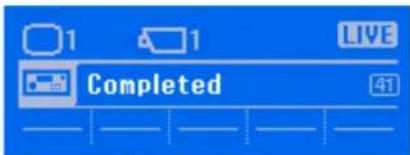 | ||
42 Current password entry 49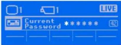 | ||
42 New password entry 49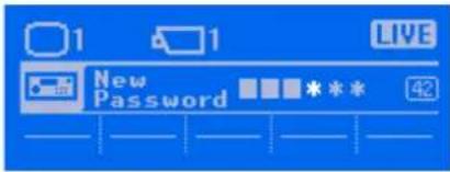 | ||
42 New password entry (confirmation) 49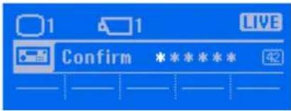 | ||
42 Password entry 50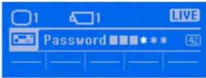 | ||
42 Confirmation of enable/disable setting for confirmation screen display when the PANIC button is pressed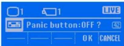 | 50 | |
42 Confirmation of enable/disable setting for confirmation screen display when the custom function buttons are pressed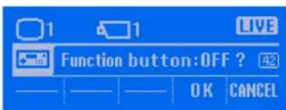 | 51 | |
| 43 Start point specification for export (year / month / day) | 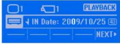 | 39 |
| 43 Start point specification for export (hour : minute : second) | 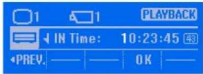 | 40 |
| 44 End point specification for export (year / month / day) | 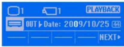 | 40 |
| 44 End point specification for export (hour : minute : second) | 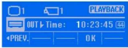 | 40 |
| 45 Export of recorded images in progress 40 | 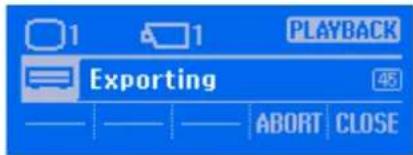 | |
Operation result screens
| Screen Refer- | ence Page |
Setting or operation success –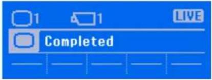 | |
Setting or operation failure –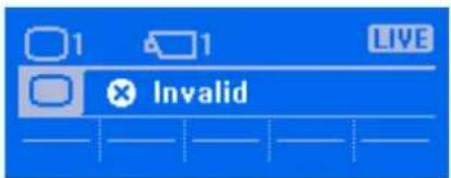 | |
Restricted setting or operation –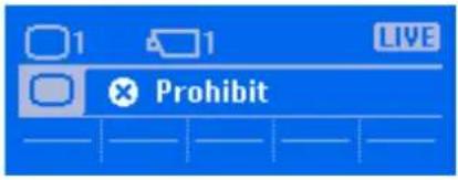 | |
Setting or operation failure –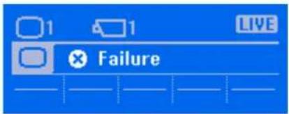 |

Pelco Mode
| Code Number | Screen Refer- | ence Page |
11 Control protocol selection 59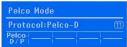 | ||
12 Baud rate selection 59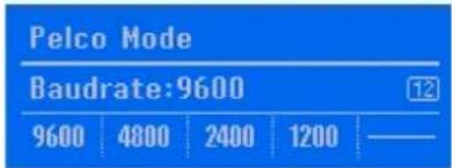 | ||
15 Controller menu 52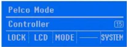 | ||
21 Control protocol selection confirmation 59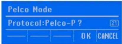 | ||
21 System lock menu 60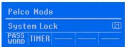 | ||
22 LCD adjustment 57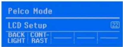 | ||
22 Baud rate selection confirmation 59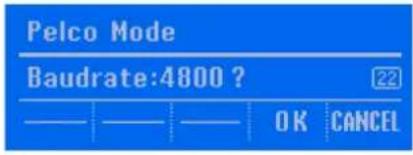 | ||
| Code Number | Screen Refer- | ence Page |
| 25 System menu 62 | 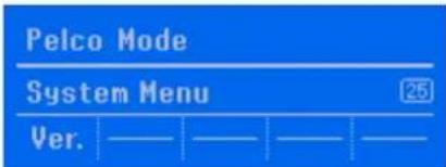 | |
| 31 LCD brightness (backlight) adjustment 57 | 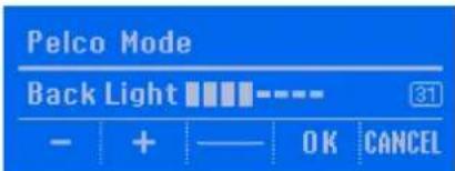 | |
| 31 Off state timer setting (duration before off state) | 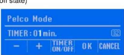 | 61 |
| 32 Mode selection 53 | 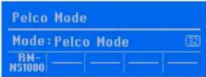 | |
| 32 Password entry 53 | 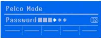 | |
| 32 Mode selection confirmation | 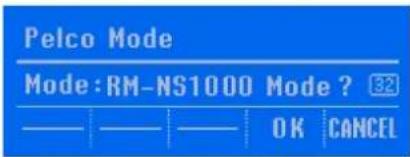 | 54 |
| 32 Setting completion | 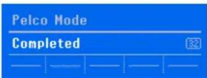 | 54 |
32 New password entry 60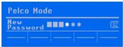 | ||
32 New password entry (confirmation) 60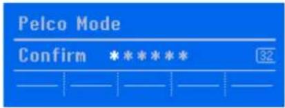 | ||
32 Current password entry 61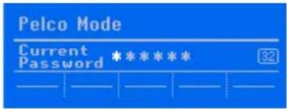 | ||
31 LCD contrast adjustment 57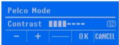 | ||
32 Version information 62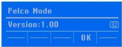 |
Operation result screens
| Screen Refer- | ence Page |
Setting or operation success –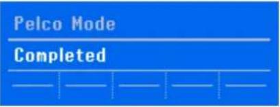 | |
Setting or operation failure –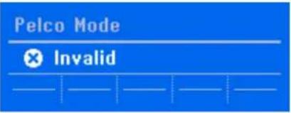 | |
Restricted setting or operation –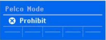 | |
Setting or operation failure –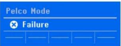 |

I/O Port
Pin arrangement of I/O port
RS-485
| Pin No. | RS-485 |
| 1 | TX+ |
| 2 | TX- |
| 3 | RX+ |
| 4 | RX- |
| 5 | GND |
- From left to right
Connection procedure for the I/O port
Connect the wires to the R-485 port as described below.
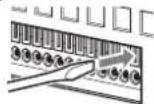
Insert a flat-blade screwdriver into the slot at the top or bottom of the hole to which you want to connect a wire (AWG No. 26 to 20), insert the wire, and then withdraw the flat-blade screwdriver from the slot.
Caution
Do not use excessive force when inserting the flat-blade screwdriver. Doing so may result in a malfunction.
①
②
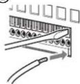
③
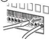
Use the same procedure to connect all of the necessary wires.
Troubleshooting
First, check the following items again. If you are still not able to resolve the problem, consult the place of purchase or a Sony dealer for business products.
The keys do not work
- Check whether the AC adapter is connected to an outlet properly.
- Check whether the POWER LED is lit green.
- Check whether the USB cable is connected properly.
- Check whether key operations cannot be accepted as a result of the lock function.
- Disconnect the USB cable from the USB port of the surveillance server or computer, and then reconnect it and check whether the keys work.
The job/shuttle dial does not work
- Check whether the JOG/SHUTTLE LED is lit. If it is not lit, press the JOG/SHUTTLE button to turn on the LED.
An external device connected to a USB connector does not work
- This unit supports standard USB 2.0 Mass Storage devices. Depending on the type of USB 2.0 Mass Storage device, however, errors may occur when writing data to the device. If errors occur when writing data, use a USB memory device of a different type.
- To ensure proper operation of USB devices, do not connect the devices via a USB hub. Connect the devices directly to the USB connectors on the unit. Operation is not guaranteed when devices are connected via a USB hub, USB switch, or extension cable.
- Refer to the documentation that came with the USB device.
Specifications
General
Interface: USB 2.0 low-speed device
External connectors
USB: USB 2.0 (×2)
Microphone jack (×1)
Headphone jack (×1)
RS-485 port (×1)
Operating environment
Operating temperature:
5^ to 40^ (41°F to 104°F)
Operating humidity:
20% to 80%
(max. wet bulb temperature: 32°C (90°F))
(no condensation)
Power and miscellaneous
Power: 12 V DC
Power consumption:
Max. 1.0 A
AC adapter: 100-240 V AC, 50/60 Hz
Dimensions:
$$ 4 0 9. 0 (\mathrm{W}) \times 1 1 1. 5 (\mathrm{H}) \times 1 7 0. 0 (\mathrm{D}) \mathrm{mm} $$
$$ (1 6 ^ {1} / _ {8} (\mathrm{W}) \times 4 ^ {1} / _ {2} (\mathrm{H}) \times 6 ^ {3} / _ {4} (\mathrm{D}) \text {in.}) $$
Weight: Approx. 1,200 g (2.6 lb.)
Accessories
AC adapter (×1)
First Step Guide (×1)
CD-ROM (User's Guide (this document)) (×1)
Warranty booklet (×1)
Design and specifications are subject to change without notice.
Note
Always verify that the unit is operating properly before use. SONY WILL NOT BE LIABLE FOR DAMAGES OF ANY KIND INCLUDING, BUT NOT LIMITED TO, COMPENSATION OR REIMBURSEMENT ON ACCOUNT OF THE LOSS OF PRESENT OR PROSPECTIVE PROFITS DUE TO FAILURE OF THIS UNIT, EITHER DURING THE WARRANTY PERIOD OR AFTER EXPIRATION OF THE WARRANTY, OR FOR ANY OTHER REASON WHATSOEVER.
Dimensions
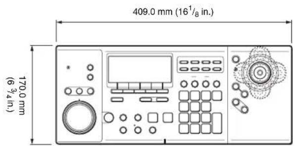
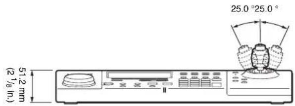
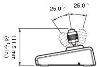
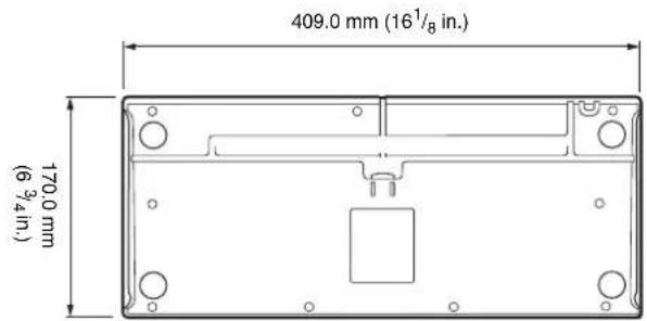

- Table of Contents
- Chapter 1 Introduction
- Chapter 2 Operations in RM-NS1000 Mode
- Chapter 3 Operations in Pelco Mode
- Chapter 4 Other Information
- Trademarks
- Introduction
- Chapter
- 1
- Function Overview
- Configuration example in RM-NS1000 mode:
- Note
- Configuration example in Pelco mode:
- Highly functional system controller with support for two modes
- Changing the screen (layout)
- Selecting a camera
- Camera control
- Recording images, and playing back and searching for recorded images
- System controller operation lock
- Precautions and Limitations
- Supported Systems
- Names of Parts
- Control Panel
- POWER LED
- (LOCK) button
- (PANIC) button
- (ALARM) button
- 5LCD
- Multi function buttons
- (ALL SELECT) button
- Custom function buttons
- ⑨ Camera preset area
- ○ (PRESET) button
- SET (SET) button
- Camera control area
- (CURSOR) button/LED
- PTZ LED
- IRIS buttons
- MANUAL FOCUS buttons
- 11Joystick
- 12Search and playback area
- (JOG/SHUTTLE) button/LED
- (PAUSE) button
- (PLAY) button
- Jog/shuttle dial
- 21Microphone
- 22BACK button/TOP MENU button
- 23Numeric keypad
- (DIGITAL ZOOM) button
- Left Side
- USB ports
- ② Microphone input jack
- 3Headphone jack
- Rear
- 1RS-485 port
- ②Power supply connector
- Bottom
- USB cable
- AC cord holder
- ②USB cable holder
- Operations in RM-NS1000 Mode
- 2
- Overview
- Logging On to the System
- When a password is not set for the system controller
- When a password is set for the system controller
- Viewing and Using the LCD
- Viewing the LCD
- Operating the Multi Function Menu
- Switching Modes
- Operations in the Main Screen
- Selecting a Monitor Frame
- Assigning Cameras to Monitoring Frames
- 3
- Switching between Monitoring Live Images and Playing Recorded Images
- Switching to live images
- Switching to playing recorded images
- Setting the Joystick to Mouse Mode
- Controlling Cameras
- Performing Pan, Tilt, and Zoom Operations
- Panning
- Tilting
- Zooming
- Returning All Cameras to Preset Position 1
- Using the Digital Zoom
- Returning to optical zoom
- Using Manual Focus
- Using Auto Focus
- Adjusting the Brightness of Images
- Setting Image Brightness Adjustment to Auto Mode
- Using Camera Presets
- Moving a Camera to a Preset Position
- To select with the numeric keypad:
- To select with the joystick:
- Setting a New Preset Position
- Performing a Camera Tour
- Performing Camera Tours
- Performing Shadow Tours
- Performing a Layout Tour
- Outputting Audio to the Camera
- Recording, Searching for, and Playing Back Images
- Recording Live Images
- Using the Jog/Shuttle Dial
- Using the jog dial
- Rotate clockwise
- Rotate counterclockwise
- Using the shuttle ring
- Center
- Playing Back Recorded Images
- Quick Playback
- Specifying the amount of time to rewind (BEFORE TIME)
- Specifying a date and time and then playing back recorded images
- Jumping to recorded images for playback
- Playing back from alarm history
- Operations in the Search Screen
- Searching for Recorded Images
- Specifying Advanced Search Conditions
- Notes
- Playing Back Recorded Images from Search Results
- Exporting Recorded Images
- Displaying the Export Screen
- Specifying the start point and end point during playback
- Specifying dates and times for the start point and end point
- Exporting Recorded Images as Still Images
- Locking Operation
- To Lock Operation
- To Unlock the Lock
- Press the LOCK button.
- Enter the password with the numeric keypad, and press the ENTER key.
- Setting the System Controller to the Off State
- To recover from the off state
- Adjusting the Brightness of the LCD
- Adjusting the Brightness and Contrast
- Turning On/Off the code number indication
- Multi Function Menu
- Monitor Layout
- Device
- Displaying the Camera Setup menu
- Backlight compensation (BLC)
- Day/Night function (Day/Night)
- Manual actions (Manual Action)
- Shadow tours (Shadow Tour)
- Volume
- System Lock
- Displaying the System Lock menu
- Setting the password
- Changing the password
- Setting the time until the system controller enters the off state
- Button Confirmation
- Selecting whether to display a confirmation screen when the PANIC button is pressed
- Selecting whether to display a confirmation screen when the custom function buttons are pressed
- System Menu
- Displaying the System Menu
- Viewing the version information
- Operations in Pelco Mode
- Press the (OK) button.
- Protocol
- Baudrate
- Other Information
- 4
- Screen Index
- I/O Port
- Pin arrangement of I/O port
- Connection procedure for the I/O port
- Caution
- Troubleshooting
- The keys do not work
- The job/shuttle dial does not work
- An external device connected to a USB connector does not work
- Specifications
- General
- External connectors
- Operating environment
- Power and miscellaneous
- Accessories
- Dimensions
Brand : SONY
Model : IMZNS104
Category : Security management software