
NSR1100 - Security management software SONY - Free user manual and instructions
Find the device manual for free NSR1100 SONY in PDF.


| Type of Product | Security Management Software (Network Surveillance Server hardware/software) |
| Model | NSR-1100 |
| Brand | Sony |
| Dimensions (W x H x D) | 430 x 87 x 417 mm (16.9 x 3.4 x 16.4 in.) |
| Weight | Approx. 12 kg (26.7 lb.) |
| Power Supply | 100-127 V AC / 200-240 V AC, 50/60 Hz, max 350 W |
| Internal Storage | 1 TB (SATA-II 500 GB x 2) |
| Maximum Number of Cameras | 32 IP cameras (including up to 16 analog cameras with optional NSBK-A16) |
| Recording Codecs | JPEG, MPEG-4 |
| Max Recording Frame Rate (VGA JPEG) | 240 fps total |
| Video Output | Analog RGB (mini D-SUB 15 pin) x 2, HDMI x 2 |
| Network Interfaces | 4 x RJ-45 (1000Base-T/100Base-TX/10Base-T) |
| Sensor Inputs | 8 (photo coupler, 3.3-24 V DC) |
| Alarm Outputs | 8 (mechanical relay, max 24 V DC, 1 A) |
| USB Ports | USB 2.0 (3 front, 3 rear) |
| Operating Temperature | 5°C to 40°C (41°F to 104°F) |
| Operating Humidity | 20% to 80% (non-condensing) |
| Supported Remote Clients | RealShot Manager Advanced Client via LAN |
| Motion Detection | Built-in VMD (Recorder), camera VMD, and VMF (metadata-based) |
| Rack Mounting | 19-inch, 2U height, optional rack mount kit |
| Optional Expansion | NSRE-S200 expansion storage (via Mini-SAS) |
| Audio | Audio input (front), audio output L/R (rear), supports audio recording/playback from compatible cameras |
| Inrush Current | 13 A at 100 V |
Frequently Asked Questions - NSR1100 SONY
User questions about NSR1100 SONY
0 question about this device. Answer the ones you know or ask your own.
Ask a new question about this device
Download the instructions for your Security management software in PDF format for free! Find your manual NSR1100 - SONY and take your electronic device back in hand. On this page are published all the documents necessary for the use of your device. NSR1100 by SONY.
USER MANUAL NSR1100 SONY
Network Surveillance Server
User's Guide
Before operating the unit, please read this manual thoroughly and retain it for future reference.
NSR Series
IPELA
Table of Contents
Chapter 1 Introduction
Overview......6
Features and Functions ....8
Front (When the Cover is Opened) 8
Rear 9
System Requirements ....10
Reference Data for Installation....11
Current Consumption and Inrush Current 11
Storage Capacity for Recorded Data 11
Recording Duration Guide 11
Number of Cameras.... 11
Chapter 2 Administration Menu
Overview....12
Displaying the Administration Menu ....12
Changing Initial Settings with the Setup Menu....13
Displaying Setup Menu 13
Details on Setting Items 13
Configuring Settings Related to Servers....20
Installing Patch Files ....21
Saving and Restoring Configuration Data ....22
Saving Configuration Data.... 22
Restoring Configuration Data 23
Exporting System Information 24
Chapter 3 Basic Operation
Overview....25
Logging On to the NSR 25
Basic Window Operations ....27
Changing the Password....29
Logging Off 29
Locking the NSR 30
Shutting Down and Restarting the NSR 30
Viewing Version Information ....31
Chapter 4 Application Settings
Alarms and Events ......32
Displaying Configuration Window ....32
Registering Devices ....33
Selecting Automatically Detected Cameras and Registering Them Simultaneously.... 33
Registering Devices Manually 35
Changing Registration Details.... 36
Deleting Devices 36
Settings Required when Using SNC-CS20/CM120/DS10/DM110/DS60/DM160.... 37
Registering Device Groups 38
Details of Each Screen 39
Configuring Camera Video Settings ....43
Configuring Camera Operations ....44
Configuring Preset Positions 44
Configuring Camera Tours.... 45
Configuring Masks 46
Configuring Control Protocol of Analog Camera 48
Configuring Network Camera Control.... 49
Configuring Audio 49
Settings Related to Monitoring....50
Configuring Monitor Layout Settings 50
Assigning Cameras to Monitor Frames.... 57
Configuring a Second Monitor.... 57
Configuring Layout Tours.... 58
Configuring Motion Detection Settings ....59
Using the Motion Detection Function of NSR (VMD (Recorder))..... 60
Using the Motion Detection Function of the Camera (VMD (Camera)) 62
Detecting Motion by Metadata (VMF) 65
Configuring Settings Related to Storage ....70
Configuring Storage Settings 70
Configuring Settings Related to Deleting Recording Data 73
Storage Configuration Example 75
Configuring Recording Schedules....77
Configuring Schedules with Automatic Camera Registration ..... 77
Configuring Schedules Manually.... 79
Configuring Alarm Recording and Event Recording.... 81
Configuring Sensor Inputs 86
Changing Settings of Sensor Input Pins of NSR.... 86
Changing Settings of Sensor Input Pins of Camera 86
Changing Settings of Sensor Input Pins of Barionet.... 87
Adding Logical Sensor Input Pins to NSR.... 87
Deleting Logical Sensor Input Pins Created for NSR.... 88
Setting Items of the [Logical Sensor In] Tab 88
Configuring Alarm Output Settings 89
Changing Settings of Alarm Output Pins of NSR.... 89
Changing Settings of Alarm Output Pins of Camera 89
Changing Settings of Alarm Output Pins of Barionet.... 90
Setting Items of the [Alarm Out] Tab 90
Configuring Action Settings 92
Manual Action....92
Event/Alarm Actions....95
Configuring Mail Notification Settings 98
Configuring System Alert Settings ....99
Registering Users ....101
User Levels and Permissions.... 101
Registering a User 101
Changing User Settings 102
Deleting a User.... 102
Setting Items of the [User] Tab 103
Configuring the Duration to Rewind for Quick Playback.....104
Chapter 5 Operation and Control
Monitoring ....105
Monitoring Live Images.... 105
Monitoring Using Layout Tours.... 106
Monitoring Audio from Cameras 106
Functions and Operating Procedure of Main Screen.... 107
When a Click Action is Configured 112
Second Monitor (Monitor 2) 112
Monitor Frame.... 113
Controlling Cameras ....114
Performing Pan, Tilt, and Zoom Operations 114
Using Camera Presets.... 115
Performing Camera Tours 115
Recording, Searching, and Playing Images ....116
Recording Live Images 116
Playing Recorded Images.... 116
Searching Recorded Images 117
Playing Recorded Images from Search Results 118
Details of Search Window.... 119
Deleting Recorded Images....122
Protecting Recorded Images ....123
Exporting Recorded Images 124
Exporting Recorded Images 124
Exporting Recorded Images as Still Images.... 126
System Administration....127
Monitoring the Error Status.... 127
Exporting Log Files.... 128
Chapter 6 Appendix
I/O Port....130
STATUS LED 132
Troubleshooting.... 133
Specifications ....135
NSR-1200/1100/1050H.... 135
Index 136
For the State of California, USA only
Perchlorate Material - special handling may apply,
see www.dtsc.ca.gov/hazardouswaste/perchlorate
Perchlorate Material : Lithium battery contains perchlorate.
For the customers in Taiwan only

廢電池請回收
Trademarks
- "IPELA" and are trademarks of Sony Corporation.
- Microsoft, Windows, and Internet Explorer are either registered trademarks or trademarks of Microsoft Corporation in the United States and/or other countries.
- HDMI, HMI-Home Definition Multimedia Interface are trademarks or registered trademarks of HDMI Licensing LLC.
- Other products or system names appearing in this document are trademarks or registered trademarks of their respective owners.
Further, the ® or ™ symbols are not used in the text.
Before using the server, be sure to read this manual.
Introduction
Chapter
1
Overview
The NSR series is a hard disk recording server for network cameras. The NSR allows you to monitor and record network camera images (JPEG or MPEG-4). It also allows you to play back the recorded images and search through it, making the NSR a truly versatile monitoring system.
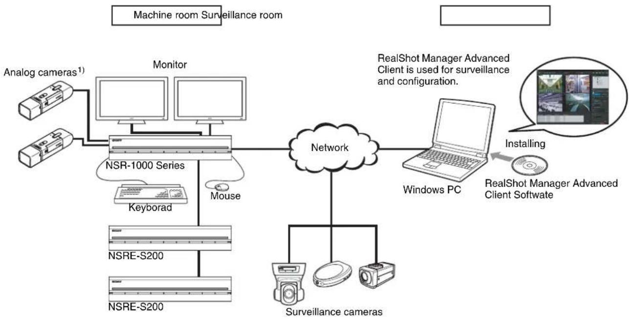
flowchart
graph TD
    A["Machine room Surveillance room"] --> B["Monitor"]
    B --> C["NSR-1000 Series"]
    C --> D["Mouse"]
    D --> E["NSRE-S200"]
    E --> F["NSRE-S200"]
    F --> G["Keyborad"]
    G --> H["Analog cameras¹"]
    C --> I["Network"]
    I --> J["Surveillance cameras"]
    J --> K["RealShot Manager Advanced Client Software"]
    K --> L["Installing"]
    L --> M["Windows PC"]
    M --> N["RealShot Manager Advanced Client is used for surveillance and configuration."]
1) The NSR-1050H is standard equipped with an NSBK-A16 analog encoder board, but the NSR-1200/1100 requires an optional NSBK-A16 expansion.
Note
With two monitors connected to the NSR, you can perform settings and monitoring operations on monitor 1 and hot spot monitoring on monitor 2.
Control compatible cameras from remote locations
You can pan, tilt, and perform zoom operations of compatible cameras.
Compatible with analog cameras
You can monitor and record images from analog cameras by connecting them directly to the unit ^1) .
1) The NSR-1200/1100 requires an NSBK-A16 (optional) expansion, while the NSR-1050H has a built-in connector.
Large-capacity hard disks allow recording for long periods of time
Equipped with large-capacity hard disks, the unit is capable recording high-quality images for extended periods of time. For reference examples, see “Reference Data for Installation” (page 11).
Slim type (2U), space-saving 19-inch rack mounting model
With the optional rack mounting kit (sold separately), the unit can be installed in a standard universal pitch EIA 19-inch rack.
High-resolution up to 480 fps (VGA, JPEG) recording
The NSR-1200 can support up to 64 cameras, the NSR-1100 can support up to 32 cameras, and the NSR-1050H can support up to 20 cameras. The NSR-1200 records images at a total frame rate of 480 fps ^1) (240 fps with the NSR-1100, 120 fps with the NSR-1050H) in VGA resolution (640 × 480 pixels) ^2) and JPEG image format (1 frame about 31 KB) for a crisp image quality.
1) Maximum frame rate when 16 cameras are connected to the recorder. Each camera has a frame rate of approximately 30 fps. This frame rate may become less because of fragmentation on the internal hard disks. Values are based on Sony measurements. These values are not guaranteed, as performance may change due to the user's operating environment.
2) In QuadVGA resolution (1,280 × 960) , the frame rate is 1/4 that of VGA resolution.
High reliability
The NSR-1200 supports RAID 5 ^1) and performs with high reliability. The system can continue functioning even if one of the hard disks develops a malfunction. Similarly, because the system software and settings are stored on the internal flash memory of the NSR, if the system software develops a malfunction, lightning-quick restoration of the system is possible. The NSR also supports uninterruptible power supplies (UPS) ^2) , making them extremely reliable systems.
1) RAID 5 is a system for dividing and storing data and parity (error correcting codes) onto more than one hard disk drive. Although this system allows continued operation should one of the hard disks malfunction, it does not guarantee restoration of lost data. In addition, due to high internal processing loads during reconstruction after you replace the malfunctioned hard disk, the unit may not be able to record images at the configured recording rate while reconstruction is in progress.
2) If the power turns off suddenly during operation, the data may be corrupted. In particular, when using the unit together with an NSRE-S200 or other expansion storage, use a UPS.
Other features
- You can display the images from up to 64 cameras (8 × 8 images) on one screen.
- The NSR is capable of manual, scheduled, and alarm recording, among others.
- The NSR is equipped with a motion detection function ^1) (Video Motion Detection (Recorder)).
- Run searches for recorded images by camera name, date, alarm, and other methods.
- Create privacy zones by using the dynamic masking functions ^2) . Dynamic masking covers pan, tilt, and zoom.
- Precise alarm processing is made possible by performing the various types of filtering ^3) that use the image processing results sent from the camera in the form of object information metadata. Because filtering can be applied to metadata that has already been recorded, you can also search for areas of interest after recording is finished.
- Audio recording and playback ^4) are also supported from compatible cameras.
1) Some functions are limited depending on the number of cameras connected.
2) Some functions are limited depending on which camera models are connected.
3) To perform motion detection and object detection using metadata, a camera that supports motion detection by metadata is required. The use of metadata is supported for up to 32 cameras.
4) Optional audio amplifiers or speakers are required.
Features and Functions
Front (When the Cover is Opened)
NSR-1200/1100/1050H
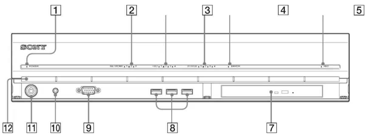
1 Power LED
Lights green when the unit is turned on. Lights amber when it is on standby.
2 Network LED (1 to 3)
Lights green when there is activity at the corresponding LAN connector at the rear of the NSR.
3 HDD LED
Blinks green when the internal hard disks are accessed. Lights amber when an error occurs with a hard disk.
4 Status LED (1 to 4)
Lights in sequence (1, 2, 3, 4) when the NSR starts. When an error occurs, the corresponding status LED lights together with the error LED, which lights or blinks to indicate the type of error. For details, see “STATUS LED” (page 132).
5 Error LED
Lights or blinks when an error occurs.
6 REC LED
Lights when recording images.
7 DVD/CD drive
Use this drive to write data from the NSR hard disks to DVD and CD.
8USB connector
Use this connector to connect a USB keyboard, USB mouse, or USB flash memory to the NSR.
9Monitor connector 1
Use this connector to connect a monitor.
Monitor connector 1 (and monitor connector 1 on the rear of the unit) and HDMI monitor connector 1 on the rear of the unit cannot be used at the same time.
10 Power switch
Press this to turn on the unit. (You cannot turn off the unit with this switch.)
11Lock
Use this in conjunction with the supplied front panel key to lock the front bezel. When the front bezel is locked, you cannot pull out the front bezel. Also, do not lock the front bezel when the front bezel is pulled out. You can distinguish the locked position from the unlocked position by looking at the lock, as illustrated below.
The front bezel is locked
The front bezel is unlocked


12 Vent holes
These openings allow air to flow from the front of the NSR to the rear.
Do not block the vent holes, allow dust to accumulate in the inner mesh of the vent holes, or obstruct the airflow in any way. Obstructing the airflow allows heat to build up inside the NSR and may result in fire or damage.
Rear
NSR-1200/1100
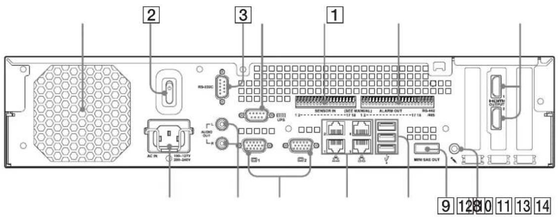
NSR-1050H
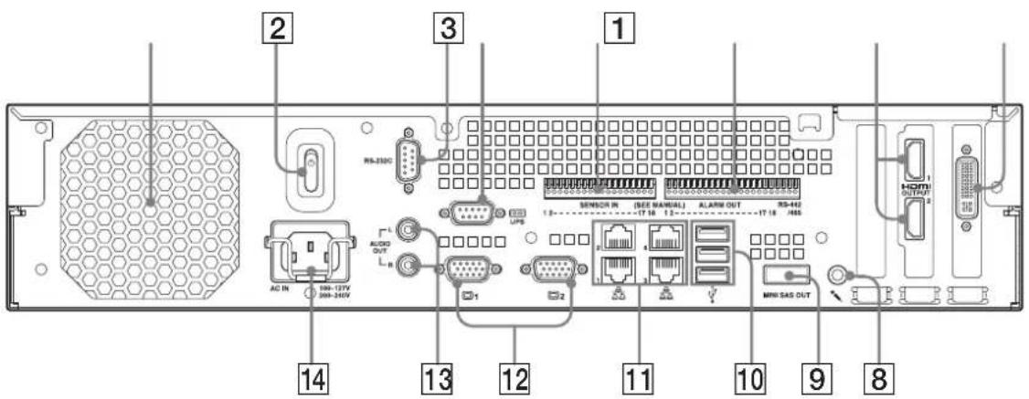
1 Fan
Take care not to obstruct the fan grille. If the grille is obstructed, heat may build up in the unit, leading to damage and/or fire.
2 Power switch
Press the switch in the ⏻ position to turn on the unit.
③RS-232C Connector
Use this connector to control analog cameras. This connector cannot be used at the same time as the RS-422/485 connector (four rightmost pins on 6 alarm output connector).
4 UPS connector (RS-232C)
Use this connector to connect the control line of the uninterruptible power supply (UPS).
Additional configuration is necessary to perform automatic shutdown with the UPS. Select [Enable] in the UPS screen of the Setup Menu, and configure the protocol according to the UPS in use. For details, see "Setting Items of UPS Screen" (page 19).
5 Sensor input connector
Use this connector to connect the sensor input lines. For connection details and wiring diagrams for sensor inputs, see "I/O Port" (page 130).
6 Alarm output connector
Use this connector to connect the alarm output lines. For connection details and a wiring diagram for alarm output, see "I/O Port" (page 130).
7 HDMI monitor connectors (1 and 2)
Use these connectors to connect monitors that support HDMI input. HDMI monitor connector 1 and 12 monitor connector 1 (and monitor connector 1 on the front of the unit) cannot be used at the same time, while HDMI monitor connector 2 and 12 monitor connector 2 cannot be used at the same time.
8 Audio input connector (Used for future expansion)
Use this connector to input audio from a peripheral audio device, such as a microphone. Plug-In Power microphones are supported.
9 Mini-SAS output connector
Use this connector to connect the mini-SAS cable used for connecting an NSRE-S200. The NSRE-S200 is an optional expansion storage unit.
10USB connector
Use this connector to connect a USB keyboard, USB mouse, or USB flash memory to the NSR.
11 LAN connectors (1 to 4)
Use these connectors to connect 10 Base-T, 100 Base-TX, or 1000 Base-T network cables. LAN1: Network cameras LAN2: Remote Clients LAN3: Used for future expansion LAN4: Used for future expansion
12Monitor connectors (1 and 2)
Use these connectors to connect a monitor. Monitor connector 1 (and monitor connector 1 on the front of the unit) and 8 HDMI monitor connector 1 cannot be used at the same time, while monitor connector 2 and 8 HDMI monitor connector 2 cannot be used at the same time.
13 Audio output connectors (L and R)
Use these connectors to output audio to a peripheral audio device.
14 Power supply connector
Use this connector to connect the power cord.
15 Analog camera cable input connector
Use this connector to connect analog cameras via the analog camera input cable. The NSR-1050H is standard equipped with this connector, but the NSR-1200/1100 requires an NSBK-A16 (optional) expansion.
System Requirements
The hardware required in order to use this recorder are as follows.
- Sony Network cameras
Contact your dealer for details about compatible Sony network cameras.
- Monitor 1)
- USB keyboard ^2)
• USB m 3) use
- USB remote controller ^4)
• Network switch
• 1000Base-T/100Base-TX/10Base-T cable
- USB memory device ^5)
1) This unit supports HDMI-compatible devices and computer displays that support RGB input. The following resolutions can be specified.
- Full High-Definition (1,920 × 1,080)
- WUXGA (1,920 × 1,200)
- Full Wide XGA (1,360 × 768)
- UXGA (1,600 × 1,200)
- SXGA (1,280 × 1,024)
- XGA (1,024 × 768)
2) Use a USB keyboard with a cable. However, keys other than the standard may not function. Wireless or infrared USB keyboards may also not function properly.
3) Use a USB mouse with a cable. However, three-button or wheel mice may not function properly. Wireless or infrared USB mice may also not function properly.
4) You can use a remote controller to control pan, tilt, and zoom operations for cameras.
- This unit supports IP Desktop USB controllers from CH Products. Other remote controllers are not supported.
5) Required when backing up system information such as logs.
- This unit supports standard USB 2.0 Mass Storage devices. Depending on the type of USB 2.0 Mass Storage device, however, errors may occur when writing data to the device. If errors occur when writing data, use a USB memory device of a different type.
Note
When using displays that support both HDMI and RGB input, we recommend using RGB input.
Reference Data for Installation
Current Consumption and Inrush Current
| Model AC input voltage | Full loading Inrush current | |
| NSR-1200 | 100 V 2.66 A | 13 A |
| 220 V 1.14 A | ||
| NSR-1100 | 100 V 1.84 A | |
| 220 V 0.79 A | ||
| NSR-1050H | 100 V 1.75 A | |
| 220 V 0.76 A | ||
| NSRE-S200 | 100 V 0.79 A | |
| 220 V 0.34 A | ||
mini-SAS cable (accessory of NSRE-S200):
SONY Part No. 9-885-130-46
Storage Capacity for Recorded Data
The storage capacities for recorded data on the NSR-1200/1100/1050H and optional expansion storage are as follows.
| Model Storage capacity for recorded data |
| NSR-1200 1,366 GB |
| NSR-1100 886 GB |
| NSR-1050H 443 GB |
| NSRE-S200 1,396 GB |
* Data capacities are approximations based on the following equation for 1 GB:
1,024 × 1,024 × 1,024 = 1,073,740,000 bytes
Recording Duration Guide
| Server Expansion storage | Number of cameras | Codec (size) | Number of days | Bitrate Frame rate | ||
| NSR-1050H | 0 units 8 | MPEG4 (VGA) | 10 | 512 kbps | 10.00 fps | |
| NSR-1100 | 0 units | 16 | MPEG4 (VGA) | 10 | 512 kbps | 10.00 fps |
| NSR-1200 | 0 units | 16 | MPEG4 (VGA) | 16 | 512 kbps | 10.00 fps |
| NSR-1200 | 7 units | 16 | MPEG4 (VGA) | 60 | 1,024 kbps | 20.00 fps |
| Server Expansion storage | Number of cameras | Codec (size) | Number of days | Quality | Frame rate | |
| NSR-1050H | 0 units 4 | JPEG | (VGA) | 4 | Level 5 | 10.00 fps |
| NSR-1100 | 0 units 4 | JPEG | (VGA) | 10 | Level 5 | 8.00 fps |
| NSR-1200 | 0 units | 16 | JPEG (VGA) | 30 | Level 5 | 1.00 fps |
| NSR-1200 | 7 units | 16 | JPEG (VGA) | 30 | Level 5 | 9.00 fps |
Number of Cameras
Maximum number of cameras
| Model | Maximum number of cameras |
| NSR-1200 | 64 |
| NSR-1100 | 32 |
| NSR-1050H | 20 |
Maximum number of analog cameras (included in total number of cameras)
| Model | Maximum number of analog cameras |
| NSR-1200 | 16 (with optional NSBK-A16) |
| NSR-1100 | 16 (with optional NSBK-A16) |
| NSR-1050H | 16 |
Maximum number of megapixel cameras (included in total number of cameras)
| Model | Maximum number of cameras |
| NSR-1200 | 8 |
| NSR-1100 | 4 |
| NSR-1050H | 4 |
Ex.) NSR-1050H (maximum number of cameras: 20)
IP cameras : 12
IP cameras (megpixel) : 4
Analog cameras : 4
Administration Menu
Chapter
2
Overview
The Administration Menu allows you to change settings that were configured with the Setup Wizard when you turned on the NSR for the first time, and also allows you to perform configurations and operations related to the server.
This chapter describes the following configurations and operations for the Administration Menu.
- "Displaying the Administration Menu" (page 12)
- "Changing Initial Settings with the Setup Menu" (page 13)
- "Configuring Settings Related to Servers" (page 20)
- "Installing Patch Files" (page 21)
- "Saving and Restoring Configuration Data" (page 22)
- "Exporting System Information" (page 24)
Note
For details on restart and shutdown procedures, see Chapter 3 “Shutting Down and Restarting the NSR” (page 30).
Displaying the Administration Menu
1 Enter the user name and password in the logon screen, and click [Administration Menu].
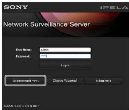
Note
If you are already logged on to the NSR, you can display the logon screen by clicking a top right of the Main screen and logging off from the dialog box that appears.
The Administration Menu screen appears.
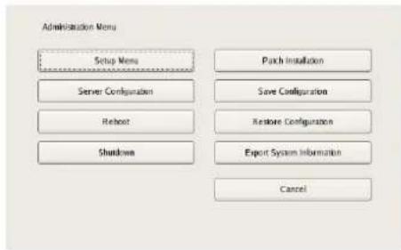
Changing Initial Settings with the Setup Menu
Use the Setup Menu to change settings that were configured with the Setup Wizard when you turned on the NSR for the first time.
Displaying Setup Menu
1 Click [Setup Menu] in the Administration Menu.
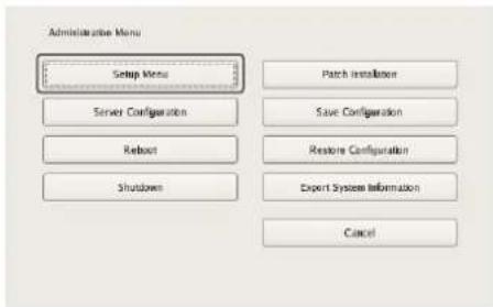
The menu items of the Administration Menu differ depending on the server and clients.
The Setup Menu appears.
2 Select the item you want to configure, and click [Select].
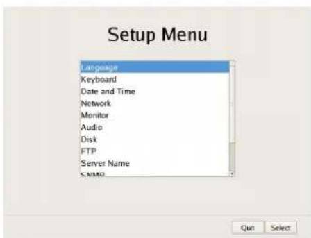
The screen corresponding to the item appears.
Details on Setting Items
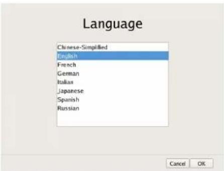
Setting Items of Language Screen
Select the language to display on the screens, and click [OK].
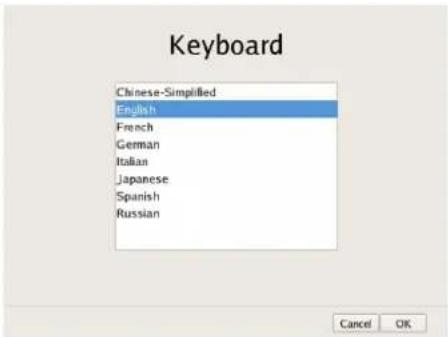
Setting Items of Keyboard Screen
Select the language of the USB keyboard connected to NSR, and click [OK].
Setting Items of Date and Time Screen
Configure the date and time of the equipment, and click [OK].
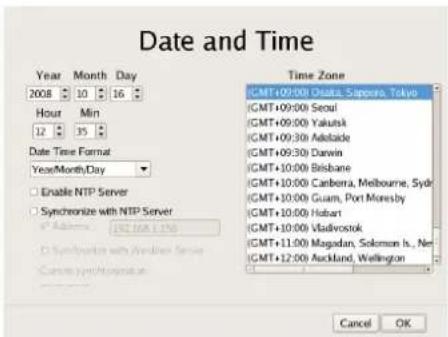
Year/Month/Day
Enter the date.
Hour/Min
Enter the time.
Date Format
Select the format for the date and time.
Enable NTP Server
Select the check box to enable the NTP server of NSR.
Synchronize with NTP Server
Select the check box to obtain the current time from another NTP server.
IP Address
Enter the IP address of the NTP server from which to obtain the information.
Synchronize with Windows Server
When a Windows server is used as the NTP server, select the check box when synchronization of the time is not possible.
Selecting this check box forces the time to be synchronized with the Windows NTP server.
Current Synchronization
This displays the IP address of the NTP server from which the current information is being obtained.
Time Zone
Select the region to configure the date and time.
Note
There is no setting for enabling or disabling daylight saving time. If you select a time zone in which daylight saving time is observed, the clock is adjusted automatically for daylight saving time.
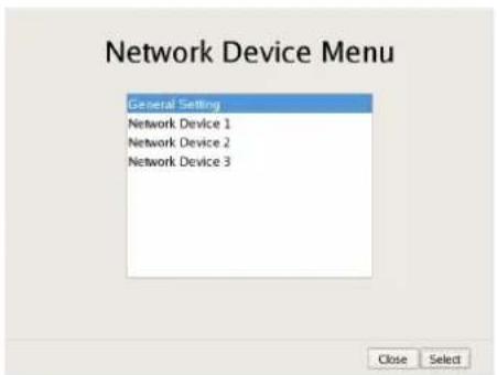
Setting Items of Network Device Menu Screen
The network settings consist of "General Network" for setting general settings, and "Network Device 1 to 3" for setting LAN ports.
Select the network you want to configure, and click [OK].
Caution
Connect the following devices to the LAN ports.
LAN1: Network camera
LAN2: Remote client
LAN3: External storage device (Such a device may not be supported depending on the software version. Consult the place of purchase.)
■Setting Items of General Network Screen
Configure each item, and click [OK].
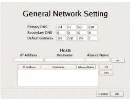
Primary DNS
Enter the IP address for the primary DNS (Domain Name Server).
Do not enter this if there is no primary DNS, or if it is not required.
Secondary DNS
Enter the IP address for the secondary DNS. Do not enter this if there is no secondary DNS, or if it is not required.
Default Gateway
Enter the IP address for the default gateway. Do not enter this is if there is only a local network or there is no need to connect to another network.
Hosts
If there is a special need to register a host name for the host file, enter a combination of the IP address and host name, and click [Add] to add the host to the list.
■Setting Items of Network Device 1 to 3
Configure each item, and click [OK].
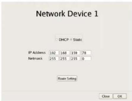
Configure the settings as follows in accordance with your environment.
To use a DHCP to obtain the address setting automatically: Select [DHCP].
To configure the address setting manually:
①Click [Static].
②Enter the following address.
IP Address
Enter the IP address.
Caution
- Before you enter the IP address, make sure there is no machine that uses the same value on the same network. Even if a machine that uses the same value does exist, an error message will not be displayed. However, be careful because more than one machine using the same value will result in incorrect operation.
• Even if you set an IP address that is prohibited under the IP address assignment rules, it will not be reflected in the system.
Example: 224.0.0.0 to 255.255.255.255
0.0.0.0
127.0.0.1, etc.
Netmask
Enter the subnet mask.
Note
The default values for a network device are shown below.
IP Address: 192.168.[0/1/2]1).1
Netmask: 255.255.255.0
1) The setting values for each of the network devices [#1/#2/#3].
Route Setting
Click this when you need to configure the route to another network.
Configure the settings as follows on the Route For Network Device 1 screen that appears.
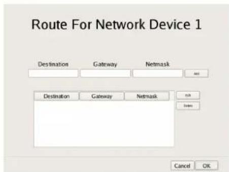
①Enter the address, gateway, and netmask of the other network to which to connect, and click [Add] to add the network to the list.
For details, contact the administrator of the network to which you will connect.
②Click [OK].
Setting Items of Monitor Menu Screen
Select the monitor you want to configure, and click [Select].
When you want to use two monitors connected to NSR, selecting the [Dual Head] check box allows you to configure the second monitor.
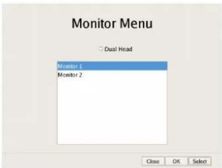
Caution
After you configure the second monitor, the system needs to be restarted while the second monitor is connected.
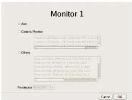
■Setting Items of Monitor 1 to 2
Select the type and resolution of the monitor connected to this equipment, and click [OK].
If you select [Auto], the type and resolution of the connected monitor is detected and the setting is configured automatically.
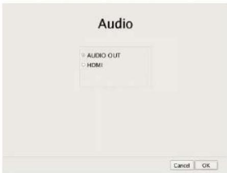
Setting Items of Audio Screen
Select the audio connector you want to use, and click [OK].
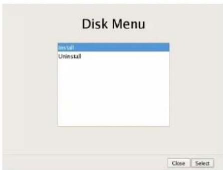
Setting Items of Disk Menu Screen
Select the operation for the hard disk drive, and click [Select].
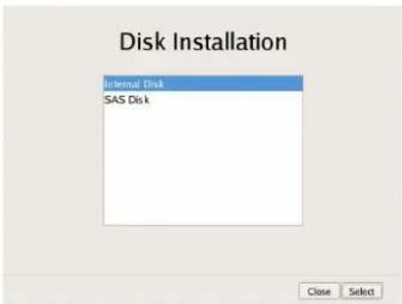
■Setting Items of Disk Installation Screen
Select the hard disk drive you want to operate, and click [Select].
■Setting Items of Internal Disk Partition Screen
Configure the partitions of the internal hard disk drive, and click [OK].
![Internal Disk Partition Volume Number: 1 Capacity: 443 GB Number of Partitions: 1 Partition1 [data1-1] 443 GB Partition2 [data1-2] 0 GB Partition3 [data1-3] 0 GB Partition4 [data1-4] 0 GB Total: 100 % Cancel OK](/content/2026/05/859819/images/cbfba9046726697b5ad132e7cc91d07c3da67257e02c0ba0b2e00b46ae9935db.jpg)
Capacity
This displays the capacity of the internal hard disk drive.
Number of Partitions
Select the number of partitions.
Partition1 [data1-1]
Select the size to allocate each partition as a percentage.
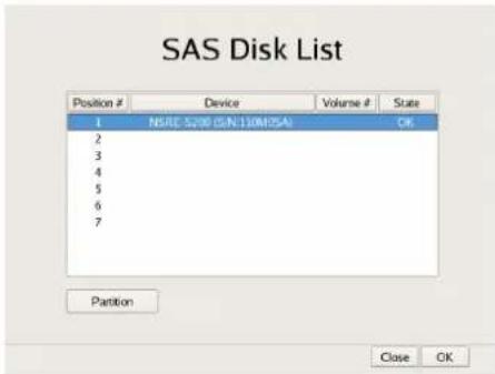
■Setting Items of SAS Disk List Screen
Select the NSRE-S200 for which you want to configure the partition settings, and click [Partition]. When you have finished configuring the settings, click [OK].
(This screen is only displayed when an NSRE-S200 is connected.)
Caution
When an NSRE-S200 is connected, use a UPS.
■Setting Items of SAS Disk Partition Screen
Configure the partitions of the internal hard disk drive of NSRE-S200, and click [OK].
![SAS Disk Partition Device: NSRE-S200 (S/N 110M0SA) Volume Number: 2 Capacity: 1360 GB Number of Partitions 2 Partition1 [data2-1] 50% 816 GB Partition2 [data2-2] 60% 544 GB Partition3 [data2-3] 10% 0 GB Partition4 [data2-4] 10% 0 GB Total: 100% Cancel OK](/content/2026/05/859819/images/abdcdcc0c9a75e2e01fa676015978cb18256533b5e349c4c3e5a42087122eb1c.jpg)
Capacity
This displays the capacity of the internal hard disk drive.
Number of Partitions
Select the number of partitions.
Partition1 [data1-1]
Select the size to allocate each partition as a percentage.
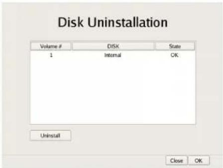
■Setting Items of Disk Uninstallation Screen
Select the hard disk drive you want to delete, and click [Uninstall]. When you have finished configuring the settings, click [OK].
If you uninstall a hard disk, all of the data on the hard disk will be deleted.
Caution
In particular, if you uninstall a hard disk drive that has multiple partitions, multiple logical volumes registered on the [Storage] tab of the Server Configuration screen will be deleted automatically. Before you uninstall a hard disk, check the [Storage] tab to confirm whether it is alright to delete the registered storage.
For details on the [Storage] tab of servers, refer to "Configuring Settings Related to Storage" (page 70).
Setting Items of FTP Screen
Configure each of the items when you want to enable the FTP server, and click [OK].
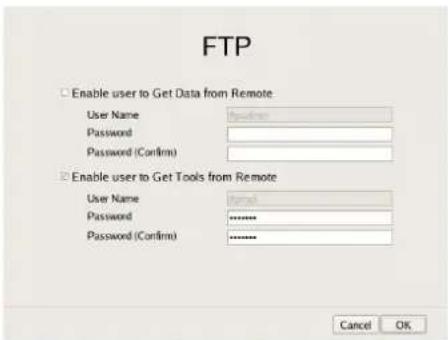
Enable user to Get Data from Remote
Select the check box to enable remote client downloading of recorded data using FTP.
If you select this check box, set the password.
User Name
This displays the user name. The user name is "ftpupdate."
It cannot be changed.
Password
Enter the password.
Enable user to Get Tools from Remote
Select the check box to enable remote client downloading of tools, operating manuals, and other documents using FTP.
This is enabled under default settings.
User Name
This displays the user name. The user name is "ftptool."
It cannot be changed.
Password
Enter the password. The default password is "ftptool."
Note
The user name and default password are both "ftptool."
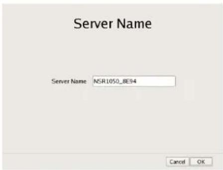
Setting Items of Server Name Screen
Enter the server name of NSR, and click [OK].
Setting Items of SNMP Menu Screen
Select [Agent] when configuring an SNMP community, and [Traps] when configuring an SNMP trap, and click [OK].
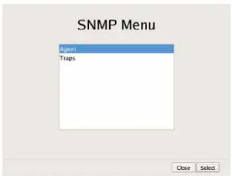
■Setting Items of SNMP Agent Screen
Configure each item, and click [OK].
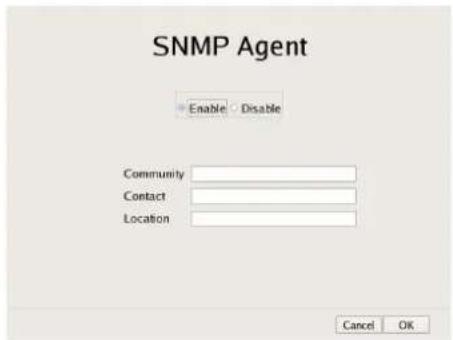
Enable
Select this to enable the SNMP agent function.
Disable
Select this to disable the SNMP agent function.
Community
Enter the SNMP community name.
Contact
Enter the contact.
Normally, enter the mail address of the system administrator.
Location
Enter the installation location of NSR.
Note
The MIB-2 object of "System" or "SystemUptime" indicated with the object ID ".1.3.6.1.2.1.1" or ".1.3.6.1.2.1.25.1.1" can be obtained.
■Setting Items of SNMP Traps Screen
Configure each item, and click [OK].
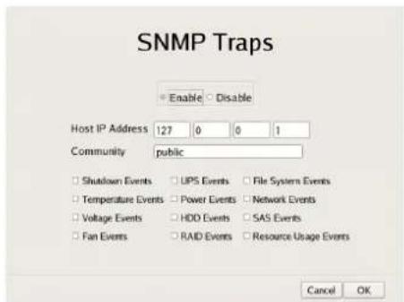
Enable
Select this to enable the SNMP traps function.
Disable
Select this to disable the SNMP traps function.
Host IP Address
Enter the IP address of the traps host.
Community
Enter the SNMP community name.
Shutdown Events
Notify when the NSR shuts down.
Temperature Events
Notify when the temperature of NSR rises.
Voltage Events
Notify when the voltage is abnormal.
Fan Events
Notify when the fan is abnormal.
UPS Events
If a UPS is connected, notify when the UPS has detected a power cut, and when the UPS has detected recovery from the power cut.
Power Events
Notify when a power malfunction occurs.
HDD Events
Notify when a hard disk drive malfunctions.
RAID Events
Notify when a RAID group rebuilds.
File System Event
Notify when a file system malfunction occurs.
Network Events
Notify when a network device malfunction occurs.
Resource Usage Events
Notify when the management domain of the hard disk drive or percentage of CPU used is abnormally high.
SAS Events
Notify when a connected NSRE-S200 malfunctions.
Setting Items of UPS Screen
Configure settings related to UPS, and click [OK].
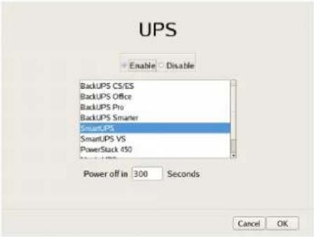
Enable
Select this when using a UPS.
If this is selected, select the type of UPS to be used from a list of UPS.
Caution
If the power turns off suddenly during operation, the data may be corrupted. In particular, when using the unit together with an NSRE-S200 or other expansion storage, use a UPS.
Disable
Select this when not using a UPS.
Power off in XXX Seconds
Enter the time from when a power cut is detected until shutdown.
Caution
For details on automatic startup after power is restored, contact your dealer.
Setting Items of Serial Port (Analog Camera) Screen
Configure settings related to the analog camera connection.
Configure each item, and click [OK].
(This screen appears when an NSR-1050H or NSBK-A16 (option) is connected.)
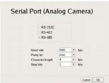
Serial standard (RS-485, RS-422, RS-232C)
Select the serial standard for connecting to the analog camera you want to control.
Baud rate
Select the communication baud rate.
Parity bit
Select the parity bit.
Character length
Select the character length.
Stop bits
Select the stop bits.
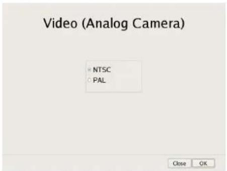
Setting Items of Video (Analog Camera) Screen
Select the video format for the analog camera to be connected, and click [OK].
(This screen appears when an NSR-1050H or NSBK-A16 (option) is connected.)
Configuring Settings Related to Servers
Configure these settings when, for example, you want to change the network settings to match the network environment of the users, or you want to centralize user administration when using multiple NSR and RealShot Manager Advanced together.
1 Click [Server Configuration] in the Administration Menu.
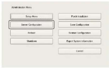
The menu items of the Administration Menu differ depending on the server and clients.
The Server Configuration screen appears.
2 Configure each item, and click [OK].
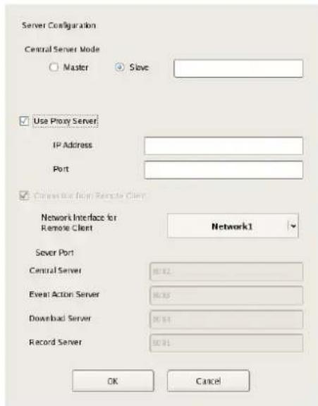
Central Server Mode
Set this if you want to manage multiple NSRs and RealShot Manager Advanced Server as one system ^1) , or you want to connect from RealShot Manager Client. You can set one master server for uniformly managing users in the system, and multiple slave servers.
1) This is for when you want to perform common user management with multiple servers, or when you want to connect from RealShot Manager Client.
Select [Master] or [Slave].
If you select [Slave], enter the master server address to which to connect.
If a server is changed from master to slave, the user information that was configured locally is discarded and the user information of the master is used.
If you want to change this setting, basically change it immediately after installation.
If you change this setting, restart the system.
Use Proxy Server
Select the check box when using a proxy server for connecting to the slave servers and master server of the central server.
IP Address
Enter the IP address for the proxy server.
Port
Enter the port number for the proxy server.
Connection from Remote Client
Select the check box to connect from a remote client.
Network Interface for Remote Client
Select the network to use for the connecting with remote client.
Server Port
Central Server
Display the port number for the central server.
Event Action Server
Display the port number for the event action server.
Download Server
Display the port number for the download server.
Record Server
Display the port number for the record server.
The settings are changed.
Caution
When the central server mode is changed, a message appears and the system restarts.
Installing Patch Files
You can install patch files distributed by Sony onto the NSR.
Patch files will be uploaded onto the official Sony Web site as more NSR-compatible cameras, for example, are added.
1 Download the patch file from the official Sony Web site, and copy it onto a USB memory device or CD/DVD.
Caution
Do not change the file name or other aspects of the patch file.
2 Click [Patch Installation] in the Administration Menu.
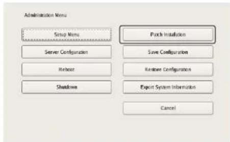
The Patch Installation screen appears.
3 Select the media on which the patch file is stored.
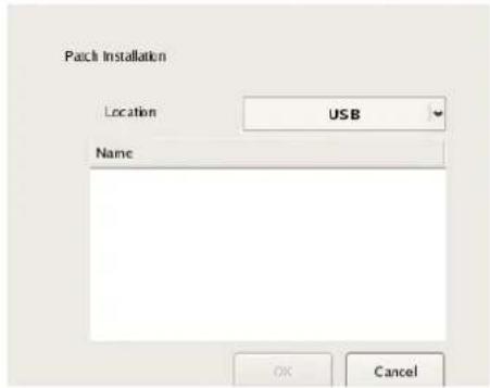
A list of patch file names appears.
4 Confirm a patch file name, and click [OK].
A confirmation message appears.
5 Confirm the content of the message, and click [Yes].
Caution
The NSR will automatically reboot after installation of certain patch files. A confirmation screen will appear if reboot is necessary. If you cannot stop your current operations, select [No] to cancel installation, and perform installation when rebooting the NSR will not be a problem.
The following screen appears during installation of the patch file.
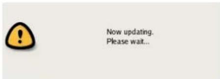
When installation is complete, the patch is applied.
Saving and Restoring Configuration Data
You can save the configuration data of NSR to external media, and restore saved configuration data.
Saving Configuration Data
Generally, the settings configured in the Server Configuration screen in the Administration Menu of the logon screen and settings configured in the settings screen after logging on are stored as configuration data.
Caution
Note that the following information is not saved.
- Recording records
- Log information
1 Click [Save Configuration] in the Administration Menu.
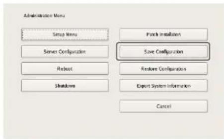
The menu items of the Administration Menu differ depending on the server and clients.
The Save Configuration screen appears.
2 Select the media to save the configuration data, enter the file name for the configuration data, and click [OK].
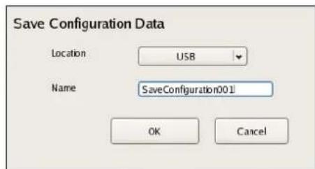
A progress bar is displayed during the backing up of the configuration data, and the configuration data is saved when the backup is finished.
3 Click [Close].
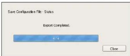
Note
When saving of the configuration data finishes, the following files are created in the save location.
Example: When the configuration data is saved under the name "Configuration001," files with the names shown below are created.
Configuration001.item
Configuration001_db.tar.gz
Configuration001_img.tar.gz
Configuration001_os.tar.gz
Restoring Configuration Data
Caution
- Note that the following information is not restored. - Recording records
- System settings such as network settings and time information (Items of [Setup Menu] (page 13)) - Logs
- The settings of the external storage itself cannot be restored, so it is necessary to configure them to the same settings as those at the time of saving.
- The configuration data cannot be restored if the first two digits of the current version (e.g.: “a.b” of “a.b.c” separated by “.”) differ from those at the time of saving or the model differs.
- When the configuration data is restored, the recording operation performed up until that point is stopped automatically. If a recording schedule has been configured, recording resumes automatically after restoration. If manual recording was performed, it needs be started again.
1 Click [Restore Configuration] in the Administration Menu.
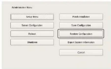
The menu items of the Administration Menu differ depending on the server and clients.
The Restore Configuration screen appears.
2 Select the location where the configuration data is saved and the configuration data, and click [OK].
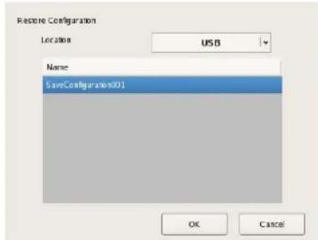
A confirmation message appears to notify you that this operation requires NSR to be restarted.
3 Click [OK].
A confirmation message appears.
4 Click [OK].
A progress bar appears during restoring, NSR restarts when the process is finished, and the configuration data is restored.
Exporting System Information
You can save NSR system information as files onto external media.
1 Click [Export System Information] in the Administration Menu.
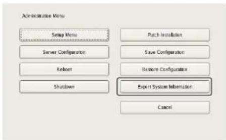
The items that appear in the Administration Menu vary depending on the server and client.
The Export System Information screen appears.
2 Select the media on which to save the system information, enter the file name, and then click [OK].
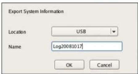
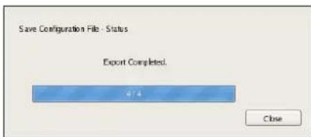
A progress bar is displayed during exporting of the system information, and the system information is saved when exporting is finished.
3 Click [Close].
Overview
This chapter describes how to perform the following basic operations on the NSR, including logging on, using various windows, changing the password, and turning off the unit.
- "Logging On to the NSR" (page 25)
- "Basic Window Operations" (page 27)
- "Changing the Password" (page 29)
• “Logging Off” (page 29) - “Locking the NSR” (page 30)
- “Shutting Down and Restarting the NSR” (page 30)
- "Viewing Version Information" (page 31)
Note
For details on settings related to devices, schedules, sensor inputs, and alarm outputs, see Chapter 4 “Application Settings” (page 32). For details on monitoring and search for and playing back recorded images, see Chapter 5 “Operation and Control” (page 105).
Logging On to the NSR
Before you can use the NSR, you must first log on.
1 Press the power switch on the front or rear panel of the NSR to turn it on.
The startup screen appears, and the progress bar for software startup appears.
Note
The fan noise may be loud for about 2 seconds after turning on the unit. This is not a malfunction.
After startup, the logon screen appears.
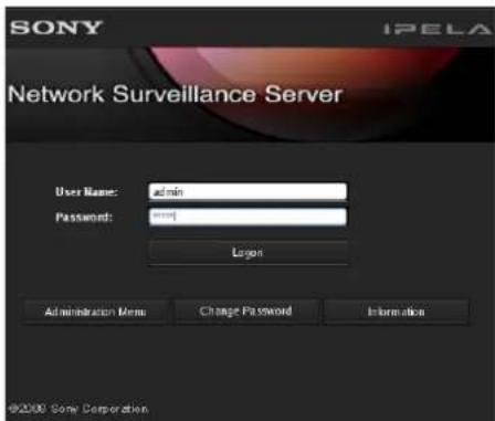
2 Enter the user name and password, and click [Logon].
Note
The first time you turn on the NSR, the administrator is the only user registered on the system. The default user name for the administrator is as follows.
User name: admin
Password: admin
Basic Window Operations
This section provides a brief description of the basic operations for each screen.
The unit includes a Main screen for monitoring images, a configuration screen for configuring various settings, and an Administration Menu for performing configurations and operations related to the NSR unit.
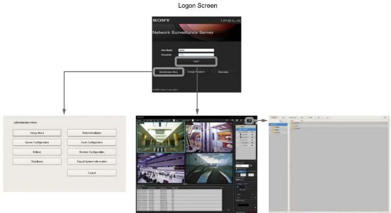
flowchart
graph TD
    A["Logon Screen"] --> B["Network Surveillance Server"]
    B --> C["Administrator Menu"]
    C --> D["Server Configuration"]
    C --> E["Rebase"]
    C --> F["Shutdowns"]
    C --> G[" \% Parch Installation"]
    C --> H[" \% Save Configuration"]
    C --> I[" \% Restore Configuration"]
    C --> J[" \% Export System Information"]
    C --> K[" \% Cancel"]
    B --> L["SYNY"]
    L --> M["IPELA"]
    M --> N["User Name: dines"]
    M --> O["Password: 1"]
    M --> P["Login"]
    P --> Q["Administrator Menu"]
    Q --> R[" \% Check Password"]
    Q --> S[" \% Manager"]
Administration Menu Main Screen Configuration Screen
Administration Menu
When you click [Administration Menu] in the logon screen, the Administration Menu screen appears. Click each button to perform various configurations and operations for the NSR unit.
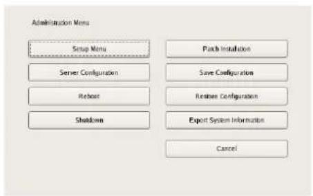
For details on settings that can be configured from the Administration Menu, see Chapter 2 “Administration Menu” (page 12).
Main screen
In the Main screen, you can monitor live images from each monitor frame, and search for and play back recorded images. To switch between live image display and playback of recorded images, click the target monitor frame, and then click [LIVE] or [PLAYBACK] on the right side of the window.
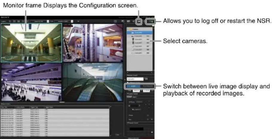
For details on monitoring and searching for and playing back recorded images, see Chapter 5 "Operation and Control" (page 105).
Configuration screen
Configure settings that are necessary for operating the NSR, such as camera registration, schedule settings, and user registration.
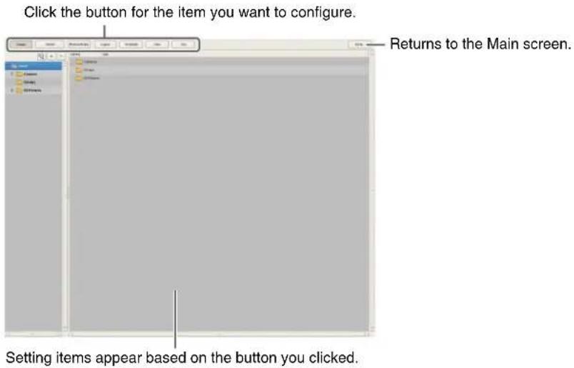
For details on setting items and how to configure them, see Chapter 4 "Application Settings" (page 32).

Changing the Password
You change the password for logging in to NSR.
Notes
- The password is extremely important to the security of this equipment. The first time you log in to NSR after purchasing the equipment, be sure to change the password before monitoring and configuring various settings. Take care to keep the password secure.
- When using a remote control for operations, create passwords consisting only of numbers.
1 Click [Change Password] on the [Logon] screen.
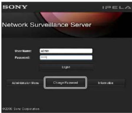
The Change Password dialog box appears.
2 Enter a new password, and click [OK].
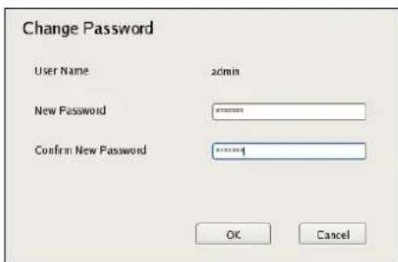
Enter the same password again in [Confirm New Password].
The password is changed.
Logging Off
1 Click in the Main screen.
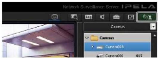
The following screen appears.
2 Click [Logoff].
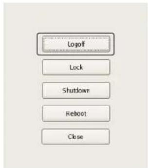
A logoff confirmation message appears.
3 Click [OK].
You are logged off the NSR, and the logon screen appears.
To log on again, enter the user name and password and click [Logon].

Locking the NSR
You can temporarily lock the screen in its current state. Use the lock function when you need to leave your seat during operation, for example.
1 Click in the Main screen.
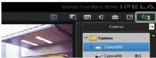
The following screen appears.
2 Click [Lock].
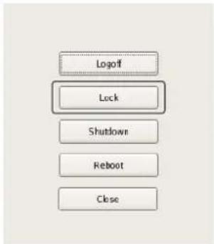
flowchart
graph TD
    A["Logoff"] --> B["Lock"]
    B --> C["Shutdown"]
    C --> D["Reboot"]
    D --> E["Close"]
Operations are locked, and the logon screen appears. To unlock operations, enter the user name and password and click [Unlock].
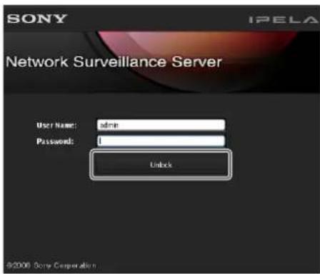
Note
Only the user that is currently logged on or a level 5 user can undo the lock function.
Shutting Down and Restarting the NSR
Always shut down or restart the NSR from the Main screen.
1 Click 📄 top of the Main screen, and select [Shutdown] or [Reboot] from the menu that appears.
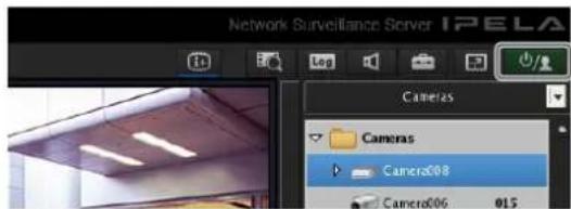
The following screen appears.
2 Click [Shutdown] or [Reboot].
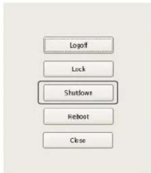
flowchart
graph TD
    A["Logoff"] --> B["Lock"]
    B --> C["Shutdown"]
    C --> D["Reboot"]
    D --> E["Close"]
A confirmation message appears.
3 Click [OK].
The NSR shuts down or restarts.
Note
Under normal conditions, the NSR shuts down or restarts after a few minutes. If the NSR does not shut down or restart after several minutes, shut it down manually by pressing the power switch located on the rear of the unit in the ⏻ position for more then five seconds.
Viewing Version Information
1 Click [Information] in the logon screen.
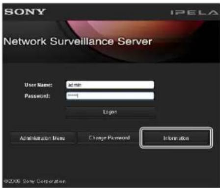
Version information for the software appears.
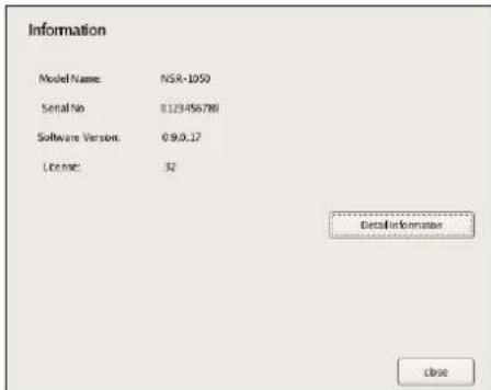

Application Settings
Chapter
4
Alarms and Events
You can configure sensor inputs, VMD, manual actions, and other triggers as alarms or events on the NSR, and record or execute actions in response. Although alarms and events are nearly identical in function, triggers of higher priority are configured as alarms and function as follows.
- When searching for recordings, you can search for alarms and events separately.
- Alarm logs are listed in the alarm history of the Main screen, and the ALARM lamp in the Main screen lights.
- The monitor frame of the camera to which the alarm is associated is displayed in a red object frame.
- The images from the camera to which the alarm is associated are displayed in the hot spot.
- You can confirm alarms and events separately in the event/alarm log.
As shown in the table below, you can configure a recording or action for the source that will become the trigger. In addition, the trigger will be determined as an alarm depending on the configured recording or action.
| Source to become trigger of event/alarm | Recording/Action Corresponding to Event/Alarm | |||
| Recording setting | Action setting | |||
| Event record | Alarm record | Camera action I/O | Client action | |
| Sensor input O | (event) | (O (alarm) | (O (alarm) | O (event) |
| VMD• V M D (camera)• V M D (recorder)• VMF | (O (event) | (O (alarm) | (O (alarm) | O (event) |
| System alert | - | - | O (alarm) | O (event) |
| Manual action | -- | O^1) | O^1) | |
1) An action is performed but is not determined to be an event or action.
Displaying Configuration Window
You can configure various settings in the Configuration window.
1 Click (Configuration) on the top right of the main screen.
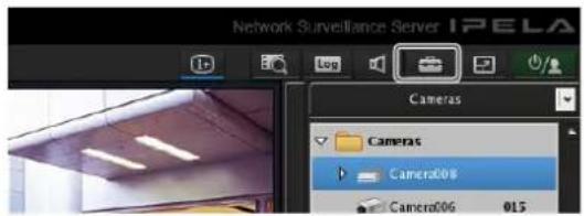
The Configuration window appears.
2 Click the button of the item you want to set at the top of the window.

The configuration screen that corresponds to the button appears.
Example: When [Device] is clicked:
The Device Configuration screen appears.
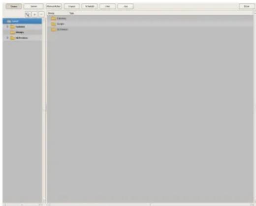
Registering Devices
You can register the devices to manage with NSR, and configure detailed settings for the operation of the devices.
There are the following way of registering devices.
- Register a camera on the network automatically For details on automatic camera registration, refer to the Installation Manual.
- Selecting Automatically Detected Cameras and Registering Them Simultaneously (page 33)
Detect the devices that exist on the same network as NSR automatically, select the cameras to register, and then register them simultaneously. - Registering Devices Manually (page 35)
Specify the IP address of a device, and register the device individually.
Notes
- When using non-Sony IP cameras (network cameras), simultaneous registration through basic configuration and automatic detection is not possible. Register the cameras manually.
- A separate registration procedure is necessary to control pan, tilt, and zoom on an analog camera. For details, see "Configuring Control Protocol of Analog Camera" (page 48).
Selecting Automatically Detected Cameras and Registering Them Simultaneously
You can detect the devices that exist on the same network as NSR automatically, select the cameras to register, and then register them simultaneously. You can also configure the IP addresses and port numbers of the cameras during registration. Entering the administrator ID and password of cameras enables you to register the devices.
1 Click [Device] at the top of the Configuration window.
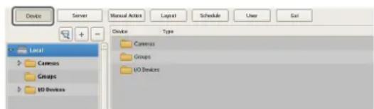
The Device Configuration screen appears.
2 Click (Camera Auto Registration).
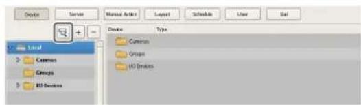
The Camera Auto Registration dialog box appears.
3 Select [Open Multiple Camera Registration Window], and click [OK].
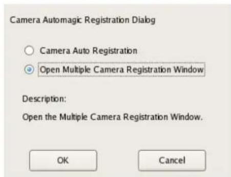
Devices are searched for automatically, and the Multiple Camera Registration dialog box appears. The Multiple Camera Registration dialog box displays a list of the results of the automatic search.
When you want to configure settings such as the user name and password of the administrator and the IP addresses for the devices, proceed to Step 4. When you want register the devices with the information from the automatic search as is, proceed to Step 5.
4 Configure each item.
Enter the administrator user name and password. It is possible to enter the setting values individually, but the following shows how to enter the same setting values for multiple devices simultaneously.
①Select the check boxes of the devices for which you want to enter setting values, and click the [Input All] button.
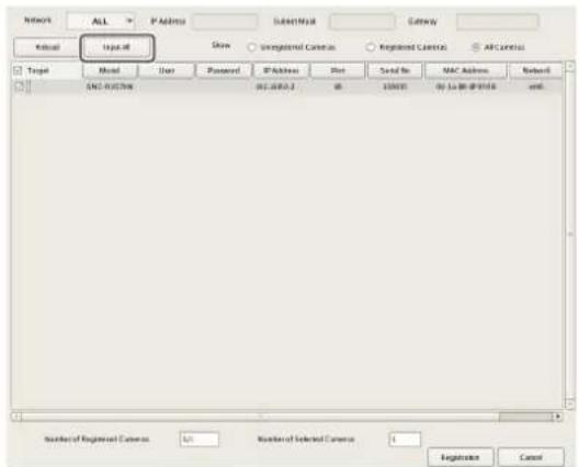
The Input All dialog box appears.
②Select the check boxes of the items you want to enter, enter the necessary information, and click [OK].
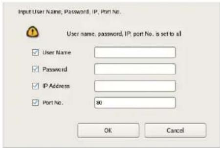
For details on each of the items, refer to "Setting Items of Input All Dialog Box" (page 41).
The dialog box closes, and the Multiple Camera Registration dialog box reappears.
5 Select the check boxes of the devices you want to register, and click the [Register] button.

Caution
If you click the [Reload] button, the automatic search is performed again. Take care because apart from the user name and password of the administrator, all of the values you entered up until now will be replaced with the results obtained with the automatic search.
The devices are registered to NSR.
Registering Devices Manually
Specify the IP address of a device to register the device individually.
Note
Before registering a device, start the browser and connect directly to the device to confirm that images from the camera can be seen. Also, for the IP address of the camera, use the IP address that was entered in the browser.
1 Click [Device] at the top of the Configuration window.
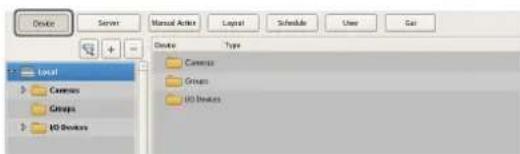
The Device Configuration screen appears.
2 Click + (Add).
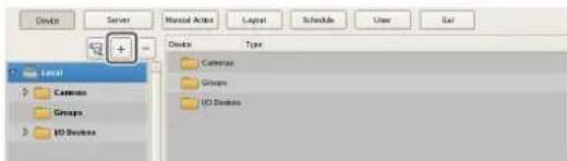
The Add Device dialog box appears.
3 Configure each item, and click [OK].
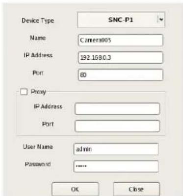
For details on each of the items, refer to "Setting Items of Add Device Dialog Box" (page 42).
When registering a camera server (SNT series, etc.):
The following dialog box appears. Select the channel to use, and click [OK].
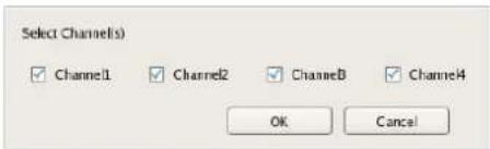
Note
A check is performed to determine whether the maximum number of registered cameras has been exceeded during processing. If the maximum number has been exceeded, a warning message appears to notify you and processing stops.
The device is registered to NSR, and is added to the list.
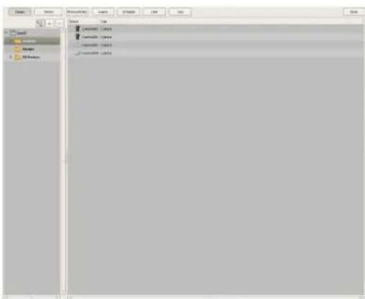
Caution
If you specify an IP address and port number that duplicates that of an already registered device, a warning appears and the device cannot be registered.
Changing Registration Details
This section describes the procedure for changing the settings on the [General] tab of the Device Configuration screen.
The items on the [General] tab allow you set multiple cameras simultaneously.
Note
Some of the setting items differ depending on whether you are configuring the settings of one camera or the settings of multiple cameras simultaneously.
- A blank is displayed for setting items with which the setting state differs for each camera. If these setting items are saved as is, the corresponding setting items of each camera are not modified. Reselecting an item from a list or entering a numeral sets the new value for all of the cameras.
- If a common value cannot be set for multiple cameras, that setting item is unavailable. Change the combination of cameras to select, and then configure the setting.
1 Select the camera(s) you want to change the registration details of on the Device Configuration screen.
You can also select multiple cameras at once by holding down the Shift key or Ctrl key while selecting.
The camera registration details appear.
2 Click the [General] tab, and modify the settings of the items you want to change.
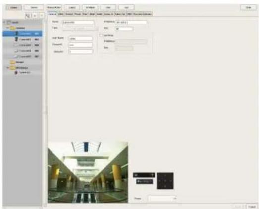
For details on each of the items, refer to "Setting Items of the [General] Tab" (page 39).
For details on Generic Camera, refer "Settings Required when Using SNC-CS20/CM120/DS10/DM110/DS60/DM160" (page 37).
3 After configuring each item, click [Apply].
The settings are changed.
Deleting Devices
1 Select the camera you want to delete on the Device Configuration screen.
You can also select multiple devices at once by holding down the Shift key or Ctrl key while selecting.
2 Click (Delete).
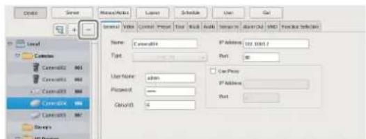
A confirmation message appears.
3 Click [Yes].
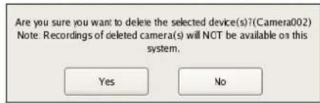
The device is deleted.
Caution
- When a camera is deleted, "No Camera" is displayed in the monitoring window in the layout. In the case of the default layout, a camera is assigned to the empty monitoring window the next time a camera is registered.
- If you delete a camera, you will no longer be able to find data recorded under the name of that camera. The recorded data is not deleted at that time. The recorded data becomes target for deletion at the point in time when the criteria for deleting the recordings or overwriting the data in storage are met. For details, refer "Configuring Settings Related to Storage" (page 70).
Settings Required when Using SNC-CS20/CM120/DS10/DM110/DS60/DM160
With the following six models of camera, other functions are restricted depending on the setting values of the functions to be used. It is necessary to prioritize and select the functions you want to use before you configure various settings.
• S N C - C S 2 0
• SNC-CM120
• S N C - D S 1 0
• SNC-DM110
• S N C - D S 6 0
• SNC-DM160
Flow when Using SNC-CS20/CM120/DS10/DM110/DS60/DM160
When using any of the above cameras, first select the combination of functions to use, and then configure various settings. First, you must select a combination of functions and then perform the setup. When you select the combination of functions, the setting range for each item is determined automatically. Therefore, it is important to select the combination of functions carefully according to the intended use of the camera.
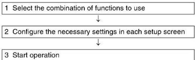
flowchart
graph TD
    A["1 Select the combination of functions to use"] --> B["2 Configure the necessary settings in each setup screen"]
    B --> C["3 Start operation"]
Caution
- The available settings and setting value ranges will vary depending on the function combination. Be sure to configure the settings to match the intended operation.
Example 1: When a certain codec is used, the motion detection function will not be available. Choose a combination with this codec only if motion detection function settings are not required.
Example 2: When a combination with an available setting value range of 1 to 50 has been selected, the available range on the respective setup screens will be limited to 1 to 50 even if the camera setting range is 1 to 100. - Be sure to select the function combination first and then configure the settings. If you select or change the function combination after starting to configure settings, the available ranges for values will also change depending on the function combination, which may lead to earlier settings being altered.
Example: 70 was selected for an item with an available range of 1 to 100, but the available range later became 1 to 50 because of a function combination change, and the setting was altered to 25.
- After changing a setting, be sure to check all settings before starting operation. If the changed value is within the available range, there will be no problem, but if it is out of range, the setting will automatically be changed to a value within the range.
1 Click [Select Camera Function] on the [Function Selection] tab of the Device Configuration screen.
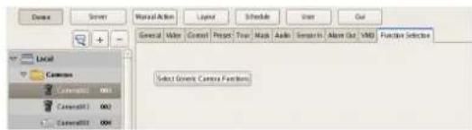
A screen for selecting the function combination to use with camera appears.
2 Select the function combination one line at a time in order from the top left, and click the [OK] button.
Select the function you want to set with [Item], and select the setting value with [Parameter].
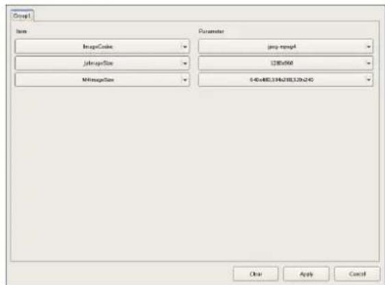
Notes
- The control range is narrowed down based on your item selection sequence and parameters. The items and values selectable on subsequent lines will change accordingly.
- If you change a selected line, all lower lines will revert to the non-selected condition. Note that the function combination selected here determines the setting range for the various setup screens.
3 Configure the other items on the [General] tab.
Also configure the settings in each screen as necessary.
![SONY NSR1100 - Configure the other items on the [General] tab. - 1](/content/2026/05/859819/images/1a3bed2ddf55d30734edfb11ecfdf04ba0b61a0b28fbad106752525536005b4b.jpg)
4 After completing the setting procedure, check all the settings to make sure they are set to appropriate values.
5 Start operation.
Registering Device Groups
You can set a device group for each floor or region that a device is installed in order to improve management efficiency. Also, you can set the permissions for the operations users and user groups can perform for each device group.
Registering a Device Group
Select [Group] in the tree on the left of the Device Configuration screen, and click (Add) to add a group.
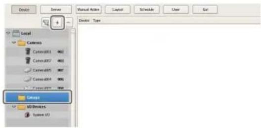
Note
When you want to create a sub-group below a group, select the upper group and click (Add).
Note
When you want to rename a group, click a group name selected in the tree and then enter the new group name.
Next, add devices to the device group.
Adding Devices to a Group
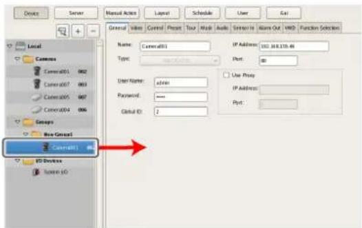
Drag and drop the devices you want to belong to the group onto the icon of the group in the tree to add them to the group.
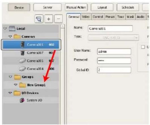
Removing Devices from a Group
Drag the icons of the devices you want to remove from the group outside of the tree.
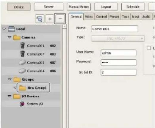
Deleting a Group
Select the group you want to delete in the tree, and click - (Delete) to delete the group.
Details of Each Screen
Setting Items of Device Configuration Screen
This screen displays a list of the devices registered to NSR. It is displayed by clicking [Device] in the Configuration screen.
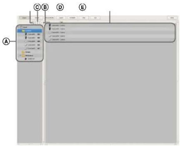
ⒶTree Structure
This displays a list of the devices registered to NSR in a tree structure.
Selecting a device from the tree structure displays the items corresponding to the selected device in area Ⓔ.
⑧ (Camera Auto Registration)
This displays the Camera Auto Registration dialog box (page 34) for automatically searching for and registering cameras connected to the network.
© (Add)
This displays the Add Device dialog box (page 42) for registering a device manually.
(D) (Delete)
This deletes a device.
Select the device you want to delete from the tree structure or device list, and click this button to delete the device.
EDevice List
This displays a list of the devices belonging to the device group selected in the tree structure on the left.
Setting Items of the [General] Tab
This tab allows you to change the settings of the device selected in the tree structure on the left.
After configuring each item, click [Apply] to save your settings.
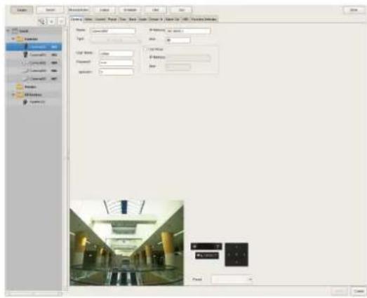
Name
Enter the name to assign to the device to be added. It can be up to 32 characters and consist of alphanumeric characters and some symbols (periods (.), hyphens (-), underscores (_)).
Type
This item displays the camera type. It cannot be changed.
User Name
Enter the user name for connecting to the device. It can be up to 32 characters and consist of alphanumeric characters and some symbols (periods (.), hyphens (-), underscores (_)).
Password
Enter the password for connecting to the device. It can be up to 32 characters and consist of alphanumeric characters and some symbols (periods (.), hyphens (-), underscores (_)).
Caution
The user name and password for connecting to a device cannot be changed from NSR. To change them, access the camera directly from a Web browser on a computer. If the user name and password for the administrator of a registered camera are changed, the NSR settings also need to be changed.

Global ID
Enter a number for the global ID.
In NSR and RealShot Manager Advanced, cameras are managed by assigning IDs to the connected cameras individually.
Also in a system in which multiple NSR and RealShot Manager Advanced are used as servers, an ID is assigned globally to all cameras connected to each server. You can use a global ID to specify the cameras to perform monitoring directly from RealShot Manager Advanced of a remote client without being aware of each server.
IP Address
Enter the IP address for the camera.
Port
Enter the port number on the camera side for when connecting with the camera. The default setting is "80."
Proxy
Set this when the camera will be accessed via a proxy server.
Enable
Select the check box, and configure the following items.
IP Address
Enter the IP address for the proxy server.
Port
Enter the port number for the proxy server.
Preview
This displays the images from the camera.
Apply
This saves the settings.
Cancel
This cancels the settings.
Setting Items of Multiple Camera Registration Dialog Box
This dialog box displays the results of the automatic search, and allows you to register the detected devices simultaneously.
It is displayed by selecting [Open Multiple Camera Registration Window] in the Camera Auto Registration dialog box (page 34), and clicking [OK].
After configuring each item, click [Register].
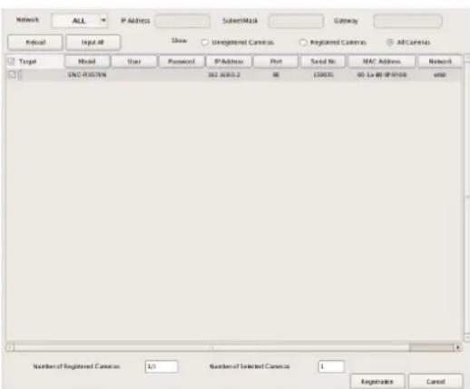
Network
A list of the devices connected to the network selected in the drop-down menu is displayed.
Reload
This performs the automatic search again.
Take care because apart from the user name and password of the administrator, all of the values you entered up until now will be replaced with the results obtained with the automatic search.
Input All
This displays the Input All dialog box (page 41).
Show
This allows you to use the following conditions to narrow down the display of devices shown in the device list.
Unregistered Cameras
This displays only the devices that have not yet been registered to NSR.
Registered Cameras
This displays only the devices that have already been registered to NSR.
All Cameras
This displays all of the devices detected with the automatic search.
Device List
This displays a list of the devices detected with the automatic search.
Register
Select the check boxes of the devices to register to NSR.
Model
This displays the type of device.
User
Enter the user name for connecting to the device.
Password
Enter the password for connecting to the device.
IP Address
This displays the IP address of the device.
Port
This displays the port number on the device side for when connecting with the device.
The default setting is "80."
Serial No.
This displays the serial number of the device.
MAC Address
This displays the MAC address of the device.
Network
This displays the network in which the device is corrected.
Status
This displays the current status of the device.
Caution
The user name and password for connecting to a device cannot be changed from NSR. To change them, access the camera directly from a Web browser on a computer. If the user name and password for the administrator of a registered camera are changed, the NSR settings also need to be changed.
Registration
This registers the devices with check marks to NSR, and closes the dialog box.
Cancel
This cancels the registration and close the dialog box.
Setting Items of Input All Dialog Box
This dialog box allows you to configure the following items simultaneously when registering devices detected with the automatic search.
It is displayed by clicking [Input All] in the Multiple Camera Registration dialog box (page 40).
Select the check boxes of the items you want to set, enter the setting values, and click [OK].
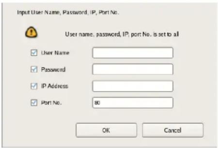
User
Enter the user name for connecting to the device. It can be up to 32 characters and consist of alphanumeric characters and some symbols (periods (.), hyphens (-), underscores (_)).
Password
Enter the password for connecting to the device. It can be up to 32 characters and consist of alphanumeric characters and some symbols (periods (.), hyphens (-), underscores (_)).
IP Address
Enter the IP address for the device.
You can also register multiple devices simultaneously. In such a case, the value of the IP address you entered becomes the beginning address.
Port No.
Enter the port number on the device side for when connecting with the device.
The default setting is "80."
OK
This reflects the setting values in the device list of the Multiple Camera Registration dialog box, and closes the dialog box.
Cancel
This cancels your settings, and closes the dialog box.
Setting Items of Add Device Dialog Box
Enter the setting items when registering a device manually. This dialog box is displayed by clicking (Add) on the Device Configuration screen (page 39). After configuring each item, click [OK].
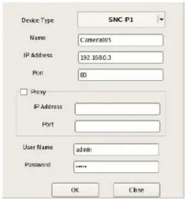
Device Model
Select the model name for the camera.
Normally, select "Auto Connect."
When setting this manually, select the model name.
Name
Enter the name to assign to the camera to be added. It can be up to 32 characters and consist of alphanumeric characters and some symbols (periods (.), hyphens (-), underscores (_)).
IP Address
Enter the IP address for the camera.
Port
Enter the port number on the camera side for when connecting with the camera. The default setting is "80."
Proxy
Set this when the camera will be accessed via a proxy server.
Enable
Select the check box, and configure the following items.
IP Address
Enter the IP address for the proxy server.
Port
Enter the port number for the proxy server.
User
Enter the user name for connecting to the device. It can be up to 32 characters and consist of alphanumeric characters and some symbols (periods (.), hyphens (-), underscores (_)).
Password
Enter the password for connecting to the device. It can be up to 32 characters and consist of alphanumeric characters and some symbols (periods (.), hyphens (-), underscores (_)).
OK
This registers the device with the set values, and closes the dialog box.
Cancel
This cancels the registration, and closes the dialog box.
Configuring Camera Video Settings
You can configure settings related to the images captured from a camera.
1 Click [Device] at the top of the Configuration window, and select the camera for which you want to configure the settings for captured images.
The registration details of the selected camera appear.
2 Click the [Video] tab, and configure each item.
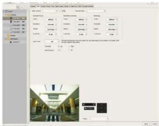
For details on each of the items, refer to "Setting Items of [Video] Tab" (page 43).
3 Click [Apply].
The settings are changed.
Setting Items of [Video] Tab
This tab allows you to change settings related to images captured from the camera selected in the tree on the left. After configuring each item, click [Apply] to save your settings.
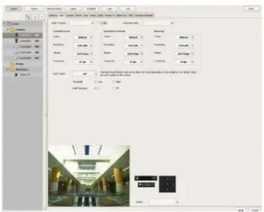
Note
The setting items and selectable values differ depending on the camera.
Video Channel
In the case of a camera server with multiple channels (SNT series, etc.), the video channel to use is displayed.
E-Flip
Select the check box to enable the E-Flip function for flipping the top and bottom of images output from the camera.
Audio Channel
Select the analog camera audio channel to tie to the analog camera.
You can also apply one setting to multiple analog cameras.
Schedule Record
Configure settings related to images for when scheduling recording.
Codec
Set the image codec for the camera. Select JPEG or MPEG4.
Image Size
Select the resolution for the camera.
Image Quality (for JPEG)
Select the image quality for images captured from the camera.
Bit Rate (for MPEG4)
Select the bit rate for images captured from the camera.
Frame Rate
Select the frame rate for images captured from the camera.
Alarm/Event Record
Configure settings related to images for when recording an alarm or event.
Codec
Set the image codec for the camera. Select JPEG or MPEG4.
Image Size
Select the resolution for the camera.
Image Quality (for JPEG)
Select the image quality for images captured from the camera.
Bit Rate (for MPEG4)
Select the bit rate for images captured from the camera.
Frame Rate
Select the frame rate for images captured from the camera.
Monitoring
Configure settings related to images for when monitoring.
Codec
Set the image codec for the camera. Select JPEG or MPEG4.
Image Size
Select the resolution for the camera.
Image Quality (for JPEG)
Select the image quality for images captured from the camera.
Bit Rate (for MPEG4)
Select the bit rate for images captured from the camera.
Frame Rate
Select the frame rate for images captured from the camera.
Light Funnel
Select the mode to use when the camera has a light funnel function.
Note
The light funnel function may not be able to be used depending on the conditions. For details, check the user's guide for the camera.
Threshold
Select the brightness for when to switch to night mode.
Hold Time
Select the time for responding to changes in brightness.
Configuring Camera Operations
In NSR, you can configure the following settings for camera operations.
- "Configuring Preset Positions" (page 44)
You can configure preset positions for the camera.
- "Configuring Camera Tours" (page 45)
You can configure camera tours for sequentially moving a camera to the pan, tilt, and zoom positions specified for presets.
- "Configuring Masks" (page 46)
You can configure the areas to mask for the camera.
- “Configuring Control Protocol of Analog Camera” (page 48)
You can configure settings for controlling the pan, tilt, and zoom on an analog camera.
Configuring Preset Positions
This section describes configuring camera preset positions.
These settings are only available for cameras with a function for configuring preset positions. The items and buttons on the [Preset] tab are unavailable for cameras without a function for configuring preset positions.
Configuring a New Preset Position
1 Click [Device] at the top of the Configuration window.
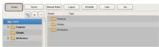
The Device Configuration screen appears.
2 Select the camera for which you want to configure the preset position, and click the [Preset] tab.
Images from the camera are displayed in the preview area.
3 Configure each item.
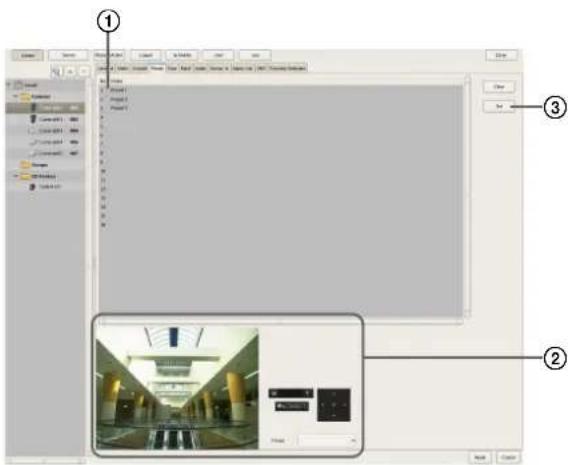
①Select the field of the position (position number) to create the preset, and enter the preset name.
②Confirm the images in the preview area while operating the pan, tilt, and zoom to adjust the camera position.
You can also select a preset, and move the camera to the preset position.
③Click [Set preset]. The current camera position is stored as a preset. When creating multiple presets, repeat Steps ① to ③.
Note
The number of presets depends on the type of camera used. For details, refer to the user's guide for your camera.
4 When you have finished configuring the settings, click [Apply].
Changing Preset Settings
1 Select the camera for which you want to change the preset position, and click the [Preset] tab.
2 When changing the preset name, re-enter the preset name in the list at the top of the screen.
3 When changing the preset position, operate the pan, tilt, and zoom to adjust the camera position.
4 Click [Set preset].
The settings are changed.
Deleting Presets
1 Select the camera for which you want to delete the preset position, and click the [Preset] tab.
2 Select the preset to delete in the list at the top of the screen, and click [Clear preset].
The preset is deleted.
3 Click [Set Preset].
Configuring Camera Tours
You can configure camera tours for sequentially moving a camera to the pan, tilt, and zoom positions specified for presets.
Note
The tour function uses the built-in tour features on a camera. As a result, tour configuration information is stored on the camera.
Setting a New Tour
1 Click [Device] at the top of the Configuration window.
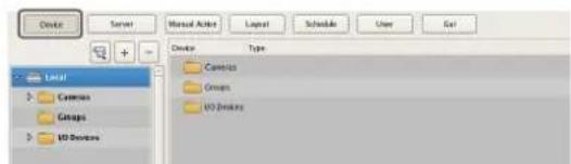
The Device Configuration screen appears.
2 Select the camera for which you want to configure the tour, and click the [Tour] tab.
Images from the camera are displayed in the preview area.
3 Configure each item.
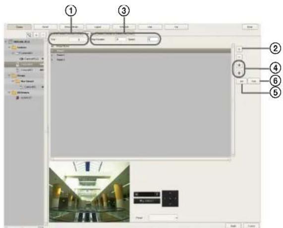
①Select the number of the tour you want to configure.
②Click (Add), select the preset to add in the Select Preset dialog box that appears, and click [OK].
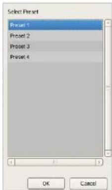
The preset is added to the list.
③Select the time that the camera stays at that position in [Stay Duration], and enter the speed (level) for moving the camera in [Speed]. For details on camera speeds (levels), refer to the user's guide for your camera.
④When you want to change the preset order, select a preset in the list and click (Move preset of tour up one place) or (Move preset of tour down one place).
⑤When you have finished configuring the presets, click [Set Tour].
⑥Click [Tour Test] to show and check the set tour.
Camera Tour Operation
In NSR, the camera tour function is achieved by configuring a stay duration and speed for each position specified by a camera preset.
Note
The configured stay duration and speed are applied to all preset positions.
Caution
Even if the values configured for the camera speed (level) are the same, actual speeds may differ depending on the models of camera. When configuring the settings of a tour, be sure to test the tour to confirm the operation.
Changing Settings
1 Select the camera(s) you want to change the registration details of on the Device Configuration screen.
2 Click the [Tour] tab, and modify the settings of the items you want to change.
3 Click [Set Tour].
The settings are changed.
Configuring Masks
Configure masks when you want to hide specific areas within images monitored by the camera. The mask function works in conjunction with the camera's pan, tilt, and zoom movements to constantly hide the specified areas.
The mask function works in conjunction with pan, tilt, and zoom movements only on Sony network cameras.
Caution
Even if you change the masks for the camera that is recording, the settings will not be reflected in the current recording file. If you want to change the masks, make the changes before you start recording.
Notes
- A mask area configured for a camera with pan and tilt functions may shift when the camera is panned, tilted, or zoomed. When configuring the mask area, allow for approximately 10% (of the full image size) of additional space around the object you wish to mask. In addition, be sure to position the object you wish to mask in the center of the monitoring screen before configuring a mask area for a camera with pan and tilt functions.
- When configuring the mask settings from a client, be sure to preview the settings before configuring them.
1 Click [Device] at the top of the Configuration window.
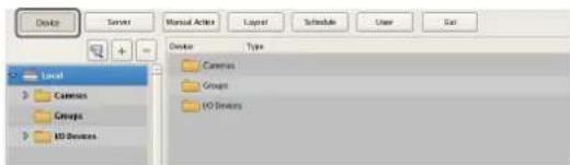
The Device Configuration screen appears.
2 Select the camera for which you want to configure the mask, and click the [Masking] tab.
Images from the camera are displayed in the preview area.
3 Configure each item.
You can configure up to 10 masks. For details on each of the items, refer to “Setting Items of [Masking] Tab” (page 47).
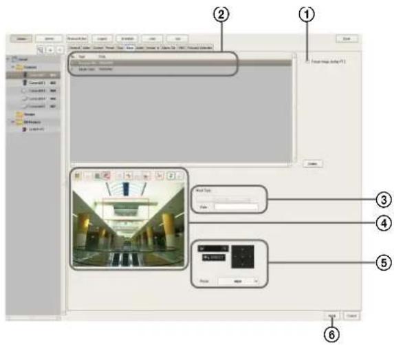
①If necessary, select [Freeze image during PTZ movement] to stop mask rendering during pan, tilt, and zoom movement.
②Enter the mask name.
③Select how the mask will be displayed. Masks can be filled with a single color or a pattern.
④Use these buttons to create and edit the mask while checking the image in the preview area.
⑤For a camera equipped with pan, tilt, and zoom functions, use these buttons to control the pan, tilt, and zoom of the camera, and to confirm whether the camera moves properly so as to hide the area you set. You can also select a preset, and move the camera to the preset position.
⑥Click [Apply]. The mask you created is added to the list. When creating multiple masks, repeat Steps ② to ⑥.
Setting Items of [Masking] Tab
After configuring each item, click [Apply].
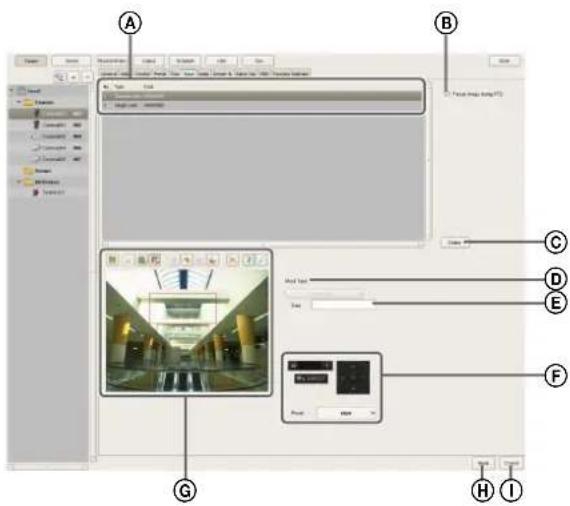
ⒶMask List
This displays a list of the masks configured for the device selected in the tree structure.
⑧Freeze image during PTZ movement
Select this check box when you want to stop mask rendering during pan, tilt, and zoom movement. If you pan, tilt, or zoom the camera while configuring a mask area, the mask moves accordingly, but the movement of the mask may lag somewhat behind the pan, tilt, or zoom movement. Selecting this check box stops mask rendering during pan, tilt, and zoom movement, which allows you to accurately configure the mask area.
©Delete
Delete the mask selected in the list.
⑭Mask Type
Select how the mask will be displayed. Masks can be filled with a single color or a pattern.
- If you selected [Single Color], specify a fill color for the mask in the dialog box that appears.
- If you selected a pattern, such as [Random Noise], you can also specify a masking level.
Caution
For [Gaussian Blur] and [Mosaic], because the blur size (in pixels) does not shift as the image is zoomed, zoom out as far as possible before setting a mask with these patterns. Otherwise, the mask will not be visible until the image is zoomed in.
©Data
The parameters that correspond to the type of mask are displayed.
Example: Single color Select the color with the color bar
Gaussian blur Radius
Mosaic Delta X/Delta Y
Random noise Amplitude
⑤Pan, Tilt, and Zoom Toolbar
This is available when the camera is equipped with pan, tilt, and zoom functions.
Use the buttons to control the pan, tilt, and zoom of the camera, and check whether or not the camera moves correctly to hide a configured area.
You can also select a preset, and move the camera to the preset position.
Caution
A mask area configured for a camera with pan, tilt, and zoom functions may shift when the camera is panned, tilted, or zoomed. When configuring the mask area, leave approximately 10% of additional space around the object you wish to mask.
©Preview Area and Tool Buttons
Use these buttons to create and edit the mask while checking the image in the preview area.

(Create/Move Area)
Use this button to create a rectangular mask or move a mask by dragging with the mouse.

(Edit Points)
Use this button to add/delete edit points and to create masks of complex shapes.

(Add Point)
Use this button to divide a line at a specific location. You can also add an edit point to a mask by clicking a line while holding down the Ctrl key.

(Remove Point)
Use this button to decrease the number of lines by one. You can also remove an edit point from a mask by clicking an edit point while holding down the Ctrl key.

(Bring to Front)
Use this button to move the selected mask to the top of a stack of overlapping masks.

(Bring Forward)
Use this button to move the selected mask up one level in a stack of overlapping masks.

(Send Backward)
Use this button to move the selected mask down one level in a stack of overlapping masks.

(Send to Back)
Use this button to move the selected mask to the bottom of a stack of overlapping masks.

(Remove Area)
Use this button to delete the selected mask.

(Refresh Image)
Use this button to refresh the still image that includes all the masks.

(Preview)
Use this button to display live images from the camera that includes the mask.
This allows you to confirm how the configured area will appear.
⑧Apply
This saves the settings.
①Cancel
This cancels the changes to the settings.
Configuring Control Protocol of Analog Camera
When an SNT-V704 is used or an NSR-1050H or NSBK-A16 (option) is connected, configure the control protocol of the connected analog camera to control the pan, tilt, and zoom.

Click [Device] at the top of the Configuration window.
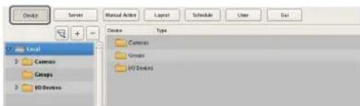
The Device Configuration screen appears.

Select the analog camera, and click the [Control] tab.
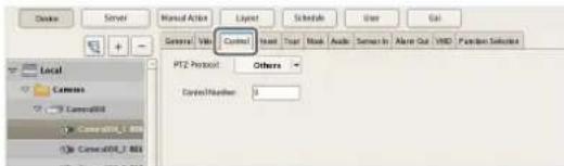
3 Configure each item.
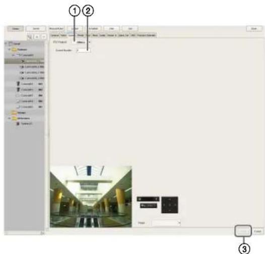
①Select a protocol in accordance with the settings of the analog camera.
②Enter the control number configured for the analog camera selected in the tree.
③Click [Apply]. Controlling the pan, tilt, and zoom on the analog camera becomes possible.
Note
Make sure that the serial port is configured according to the analog camera you are using. You can configure the serial port from the Setup Menu of the Administration Menu.
Configuring Network Camera Control
You can configure settings to control pan and tilt speed based on the zoom level of the camera.
1 Click [Device] at the top of the Configuration window.
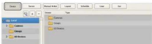
The Device Configuration screen appears.
2 Select the network camera, and click the [Control] tab.
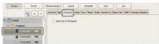
3 Select the [Auto Pan & Tilt Speed] check box, and click [Apply].
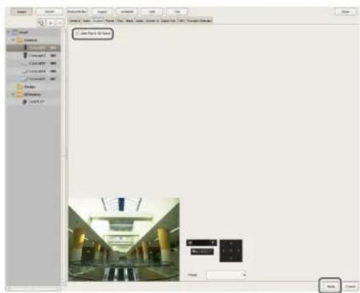
Pan and tilt speed will be controlled based on the zoom level of the camera.
Configuring Audio
Configure settings for monitoring audio from the cameras.
1 Click [Device] at the top of the Configuration window.
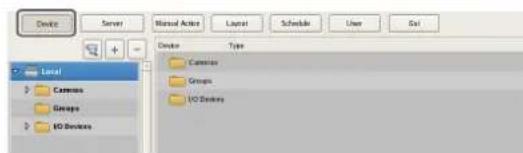
The Device Configuration screen appears.
2 Select the camera for which to enable audio, and click the [Audio] tab.
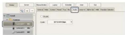
3 Configure each item, and click [Apply].
![SONY NSR1100 - Configure each item, and click [Apply]. - 1](/content/2026/05/859819/images/44ad1ffcd92f84574dcc53936b15cc144b5b2c36644d1597cfeec8eef8b1baea.jpg)
Select this check box to allow the NSR to receive audio from the camera. To monitor audio, the microphone input on the camera must also be enabled.
Caution
If you clear the check box to disable audio and then play back a recording that was created while audio was enabled, the audio will not play back. To play back the audio in such cases, select the check box and re-enable audio first.
Codec
Specify the audio codec.
Audio from the camera can now be monitored.
Settings Related to Monitoring
You can configure the following settings related to the monitor layout and camera images.
- “Configuring Monitor Layout Settings” (page 50) You can create multiple layouts according to your operating environment and objective.
- "Assigning Cameras to Monitor Frames" (page 57) You can assign a camera to each monitor frame.
- "Configuring Layout Tours" (page 58) You can sequentially switch the display of each display at a preset time.
Configuring Monitor Layout Settings
By setting the number and size of camera monitor frames, you can create a layout according to your operating environment and objective.
Notes
- When you register a camera, the layouts 2 × 2 , 3 × 3 , and 4 × 4 are created as the default layouts automatically. The size of the monitor frame cannot be changed for the default layout.
- Created layouts are saved on the machine they are created on. For example, layouts created on a remote client (RealShot Manager Advanced Client Software) are saved on the remote client.
Creating a New Layout
1 Click [Layout] at the top of the Configuration window.
The Layout Configuration screen appears.
2 Select "Custom Layout A" or "Custom Layout B" from the [Layout] tree, and click (Add).
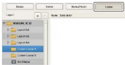
Note
"Custom Layout A" and "Custom Layout B" are preset layout groups. Use them according to your objective.
The area on the left side changes to the display for setting the layout.
3 Configure each item.
For details on each of the items, refer to "Setting Items of Layout Configuration Screen" (page 52).
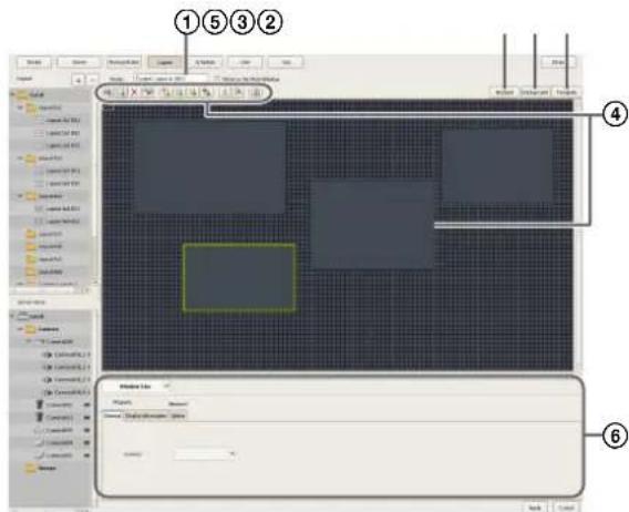
①Enter the name of the layout, as necessary. It can be up to 32 characters long.
②Set the number and layout of monitor frames. Click [Apply Template], set each item in the Insert Template dialog box that appears, and click [OK].
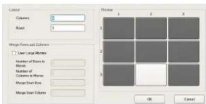
For details on each of the items, refer to "Setting Items of Insert Template Dialog Box" (page 56)
③Import an image such as a map or floor plan for the background, as necessary. Click [Insert Background Image], set each item in the Insert Background Image dialog box that appears, and click [OK].
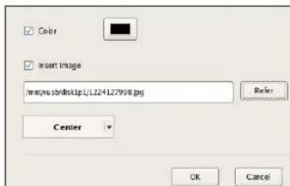
For details on each of the items, refer to "Setting Items of Insert Background Image Dialog Box" (page 56).
④Move the monitor frames to determine their positions, as necessary. Move the monitor frames by dragging them with the mouse.
⑤Set a hotspot monitor, as necessary. Click to select one monitor frame to specify as the hotspot monitor, and click [Hotspot]. A hotspot monitor displays the same images as the camera monitor frame currently selected on the main screen. To make images from the camera monitor frame easier to see, the hotspot monitor is specified to be larger than a regular camera monitor frame.
⑥Configure each tab of [Properties], as necessary. For details on the setting items of each tab, refer to "Setting Items of Properties" (page 54).
4 After configuring each item, click [Apply].
The layout is created.

Changing Registration Details
1 Select the layout you want to change the registration details of on the Layout Configuration screen.
2 Reconfigure each item.
3 Click [Apply].
The settings are changed.
Deleting Layouts
Note
Default layouts cannot be deleted.
1 Select the layout you want to delete from the [Layout] tree on the Layout Configuration screen, and click - (Delete).
A confirmation message appears.
2 Click [OK].
The layout is deleted.
Setting Items of Layout Configuration Screen
This screen is displayed by clicking [Layout] in the Configuration window.
After changing the settings, click [Apply] to save your settings.
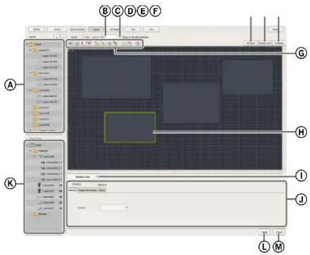
Ⓐ[Layout] Tree
This displays a list of the configured layouts in a tree structure.
Selecting a layout from the tree displays the setting details in the area on the right.
+ (Add)
This creates a new layout.
Select "Custom Layout A" or "Custom Layout B," and click this button.
Note
"Custom Layout A" and "Custom Layout B" are preset layout groups. Use them according to your objective.
- (Delete)
This deletes a layout.
Select the layout you want to delete from the tree, and click this button to delete the layout.
Note
Default layouts cannot be deleted.
BName
Enter the name of the layout. It can be up to 32 characters long.
©Show on the Main Window
Select the check box to enable this layout to be displayed on the main screen.
©Hotspot
Set the hotspot monitor.
Click to select one monitor frame to specify as the hotspot monitor, and click this button.
If you set a hotspot monitor, when you click a certain monitor frame or an alarm is generated, images are displayed on the monitor frame set as the hotspot monitor. A hotspot monitor displays the same images as the camera monitor frame currently selected on the main screen. To make images from the camera monitor frame easier to see, the hotspot monitor is specified to be larger than a regular camera monitor frame.
©Insert Background Image
This displays the Insert Background Image dialog box (page 56) for importing an image such as a map or floor plan for the background.
⑤Apply Template
This displays the Insert Template dialog box (page 56) for setting the number and layout of monitor frames.
©Tool Buttons

(Insert Image)
Use this button to display the Insert Image dialog box (page 57) for inserting an image.

(Insert Image Map)
Use this button to insert an image map.

(Remove Item)
Use this button to remove the selected item.

(Remove Assigned Cameras)
Use this button to remove the cameras assigned to the selected monitor frame.

(Bring to Front)
Use this button to move the selected image in front of all others.

(Bring Forward)
Use this button to move the selected image forward.

(Send Backward)
Use this button to move the selected image backward.

(Send to Back)
Use this button to move the selected image behind all others.

(Flip)
Use this button to flip the selected image horizontally.

(Spin)
Use this button to spin the selected image 90 degrees clockwise.

(Grid)
Use this button to display grid lines to assist in placing monitor frames and images.
©Monitor Frame
A monitor frame is created by dragging to any size in the configuration area of the layout.
This is used to display images from cameras and play back recordings.
For each monitor frame, you can specify the camera that displays images.
By configuring a large monitor frame as a hotspot monitor, you can display a larger version of the same image that appears in the currently selected monitor frame.
①Actual Size/Adjust to Window Size
When you are editing a layout and want to see the whole layout, select [Adjust to Window Size].
When you want to confirm a layout at actual scale, select [Actual Size].
①Properties Tabs
This displays tabs for configuring the advanced settings of the monitor frames, images, and image map. For details on the setting items of each tab, refer to “Setting Items of Properties” (page 54).
©[Device] Tree
This displays a list of the devices registered to NSR in a tree structure.
When you are creating a layout, you can assign cameras by dragging and dropping them from the [Device] tree to monitor frames.
Apply
This saves the settings.
MCancel
This cancels the changes to the settings.
Setting Items of Properties
■ When a monitor frame is selected:
• [ General ] Tab
Select the camera to assign to the monitor frame.
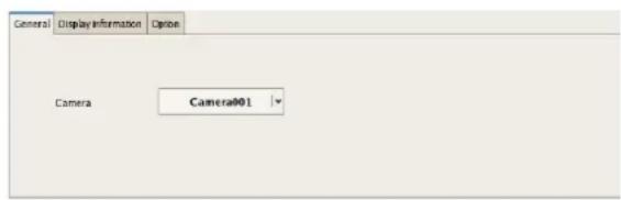
Server
Select the remote server.
This item is not displayed in the case of a client.
Camera
Select the camera to assign to the monitor frame.
• [Display Information] Tab
Select the check boxes for the items to display on the monitor frame.
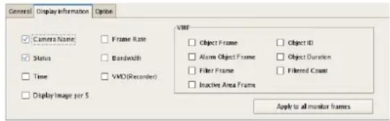
Camera Name
This displays the name of the camera set on the Device Configuration window.
Status
This displays error messages, such as “NO CONNECTION.”
Time
This displays the current time.
Display Image per Second
This displays the speed at which camera images on the computer display are refreshed.
Frame Rate
This displays the import speed for camera images.
Bandwidth
This displays the amount of bandwidth to use for transferring images over a network connection.
VMD (Recorder)
This displays the detection criteria for Video Motion Detection (Recorder).
VMF
Select the Video Motion Filter information to display in the monitor frame.
Object Frame
This displays the object frame.
Alarm Object Frame
This displays the object frame detected as an alarm.
Filter Frame
This displays the filter frame.
Inactive Area Frame
This displays the inactive area frame.
Object ID
This displays the object ID.
Object Duration
This displays the duration that an object was recognized as moving, or the duration that an object was recognized as unattended or removed.
Filtered Count
This displays the number of times the filter conditions are satisfied.
Apply to All Monitor Frames
This applies the items with check marks to all monitor frames.
• [ Options ] Tab
Select how the image size should appear when the size of the monitor frame changes.
![General Display Information Option □ [Scale to Monitor Fit] □ Keep Aspect Ratio □ Smooth Scaling □ Restrict the display 1 Apply to all monitor frames](/content/2026/05/859819/images/346b847f3289c69e3f4f82562ffe15da53913e45273409a329a5d6ac82ea9c31.jpg)
Scale to Monitor Frame
Images are enlarged or reduced to fit the monitor frame.
Keep Aspect Ratio
This maintains the image aspect ratio, regardless of the size of the monitor frame.
Smooth Scaling
This enlarges or reduces images smoothly.
It can improve the image quality when enlarging or reducing images.
Restrict the display image per second
When MPEG4 is used as the codec and the frame rate is not fast enough, the images may be skipped at irregular times. If you select the [Restrict the display image per second] check box, the re-rendering interval will become longer but the skipping of images will be reduced because only 1 frames will be selected and displayed.
Apply to All Monitor Frames
This applies the items with check marks to all monitor frames.
■When an image or image map is selected:
• [ General ] Tab
Configure settings related to the inserted image or image map.
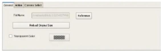
File Name
Click [Browse], and specify the image file to insert.
Reload Original Size
This displays the image at the original size.
Transparent Color
This option allows you to set one color in the image as a transparent color.
Select the check box, click within the box, and specify the color to make transparent in the dialog box that appears.
• [Action] Tab
Assign actions to the selected image or image map. If an action is assigned to the selected image or image map, clicking the mouse within the image performs the set action.
Click Action
Select the check box to enable an action, and select the action to perform.
• [Select Camera] Tab
Set the function for displaying an image of the specified camera in the specified monitor frame when you select the image or image map.
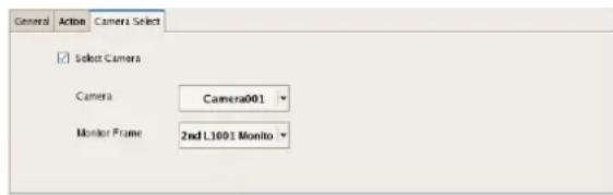
Camera Select
Select the check box to enable this function, and configure the following items.
Server
Select the remote server.
This item is not displayed in the case of a client.
Camera
Select the camera to assign to the monitor frame.
Monitor Frame
Select the monitor to display the images of the camera.
Setting Items of Insert Template Dialog Box
This dialog box creates a new layout.
It is displayed by clicking [Apply Template] on the Layout Configuration screen (page 52).
After configuring each item, click [OK].
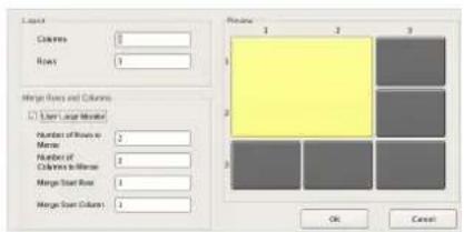
Layout
Set the number of camera monitoring windows you want to display on the screen by specifying the number of columns and rows.
Columns
For the number of columns, enter the number of monitoring windows to align horizontally.
Rows
For the number of rows, enter the number of monitoring windows to align vertically.
Merge Rows and Columns
Select the check box when you set a screen that is larger than a regular monitor window such as when using the screen as a hotspot monitor, and specify the rows and columns to preview while checking the preview area.
OK
This creates a layout in accordance with the set values, and closes the dialog box.
Cancel
This cancels your settings, and closes the dialog box.
Setting Items of Insert Background Image Dialog Box
This dialog box imports an image such as a map or floor plan for the background.
It is displayed by clicking [Insert Background Image] on the Layout Configuration screen (page 52).
After configuring each item, click [OK].
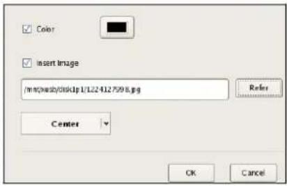
Color
Select the check box to configure a color for the background.
If you select this check box, click within the box, and specify a color in the dialog box that appears.
Image
Select the check box to insert an image for the background. If you select this check box, click [Browse], and specify the image data to insert.
Stretch
This stretches the image to fill the entire background.
Center
This displays the image in the center of the background.
OK
This inserts an image in accordance with the set values, and closes the dialog box.
Cancel
This cancels your settings, and closes the dialog box.
Setting Items of Insert Image Dialog Box
This dialog box allows you to set the image file to insert.
It is displayed by clicking on the Layout
Configuration screen (page 52).
After configuring each item, click [OK].
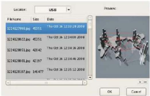
Location
Select the media containing the image file, and select the image file.
When you select the media, a list of the stored image files appears.
Preview
This displays a preview of the image file selected in the list.
OK
This inserts the selected image, and closes the dialog box.
Cancel
This cancels your settings, and closes the dialog box.
Assigning Cameras to Monitor Frames
Assign a camera for displaying images to each monitor frame.
1 Select a layout from the [Layout] tree on the Layout Configuration screen.
2 Assign the cameras to monitor frames.
The following methods are available for assigning cameras.
- Drag and drop a camera from the [Device] tree to a monitor frame.
- Select a monitor frame, and select a camera from the [General] tab at the bottom of the screen.
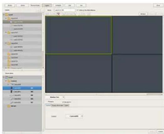
Configuring a Second Monitor
When a second monitor is installed, select the layout to use for the second monitor and configure settings related to monitor frames.
A second monitor can only be used as the hotspot monitor.
Note
The 1×1, 2×2, 3×2, and 3×3 layouts are provided in advance for a second monitor. It is not possible to assign cameras, change monitor frames, etc.
1 Select "2nd Display" from the [Layout] tree on the Layout Configuration screen.

2 Configure each item.
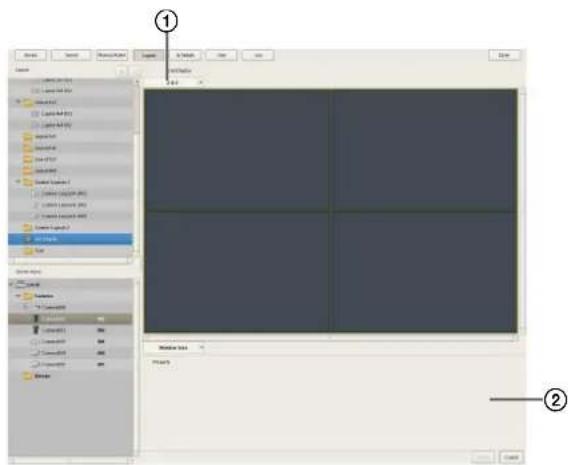
①Select the layout to use.
②Configure settings related to monitor frames, as necessary.
For details on the setting items, refer to “[Display Information] Tab” (page 54) and “[Options] Tab” (page 54) of “When a monitor frame is selected.”
3 Click [Apply].
The settings are saved.
Configuring Layout Tours
You can set a layout tour for sequentially switching the display shown on the display at a preset time during monitoring.
Creating a New Layout Tour
1 Select "Layout Tour" from the [Layout] tree on the Layout Configuration screen, and click (Add).
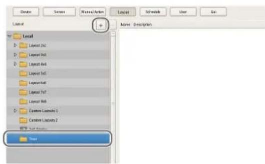
A layout tour is added to the tree.
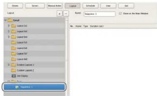
2 Create a layout tour.
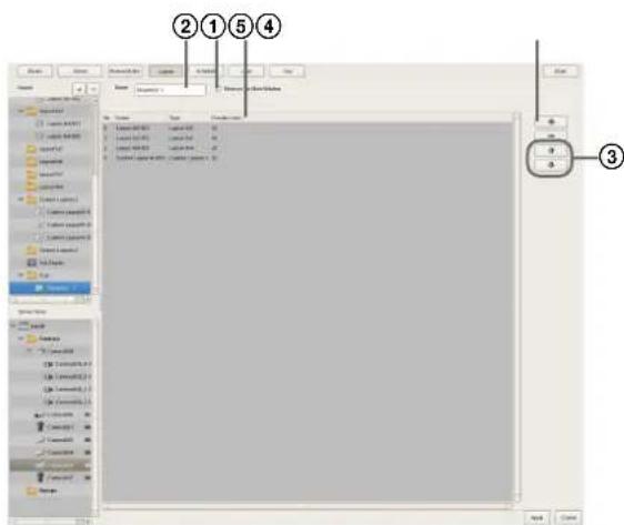
①Click (Add) on the right of the list, specify the layout and duration (seconds) in the Layout Tour dialog box that appears, and click [OK].
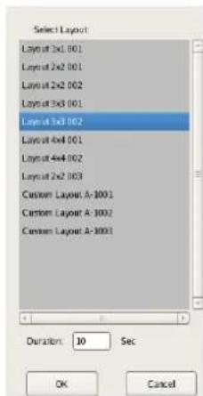
The layout is added to the list on the Layout Tour screen.
In the same way, add other layouts to display in the tour to the list.
②Enter a name for the tour.
③When you want to change the display order, select a layout in the list and click (Move layout of tour up one place) or (Move layout of tour down one place).
The layouts are displayed from the top of the list in order.
④When you want to change the duration, click the box and enter the number of seconds.
⑤Select the check box to enable this layout tour to be specified on the main window.
3 After configuring each item, click [Apply].
Changing Registration Details
1 Select the layout you want to change the registration details of from the [Layout] tree on the Layout Configuration screen.
2 Reconfigure each item.
3 Click [Apply].
The settings are changed.
Deleting Layout Tours
1 Select the layout tour you want to delete from the [Layout] tree on the Layout Configuration screen, and click - (Delete).
A confirmation message appears.
2 Click [OK].
The layout tour is deleted.
Configuring Motion Detection Settings
Motion detection is a function for detecting motion and objects from camera images or camera image metadata. In NSR, you can set one of the following types of motion detection functions for each device.
• VMD (Recorder) (page60)
This is NSR's own motion detection function.
• VMD (Camera) (page62)
This a function that uses a camera to detect motion and objects.
- VMF (page65)
This is a function that uses metadata to detect motion.
Note
Although both a camera and NSR are equipped with motion detection functions, you can reduce the load on the NSR system by using the motion detection function of the camera (VMD [camera]). Decide which one to use in accordance with the number of cameras registered and the operation configuration for recording and monitoring.
About Motion Detection and Object Detection
What is Motion Detection?
A function for detecting moving objects (such as people or cars).
What is Object Detection?
This function for detecting when a moving object has stopped (unattended) or when an object has moved from its original position (removed).
What is Motion Detection by Camera Image Metadata?
A function for detecting specific motion phenomena by applying a Video Motion Filter (VMF), consisting of motion detection criteria, to the motion-related metadata generated within the camera (no images are used, as detection is performed by metadata only). With motion detection by metadata, motion can be detected not only by metadata delivered in real time from the camera but also by recorded metadata.
Caution
- When using the motion detection function, be sure to test it before operation.
- Object detection requires at least approximately 40 second initialization period before starting. Also, moving objects that have remained still for at least approximately 40 seconds are regarded as unattended.
Using the Motion Detection Function of NSR (VMD (Recorder))
Configure the motion detection function to use in NSR.
1 Click [Device] at the top of the Configuration window.
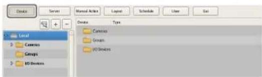
The Device Configuration screen appears.
2 Select the camera that will be the target for processing from the [Device] tree.
3 Configure each item on the [VMD] tab, and configure the motion detection area.
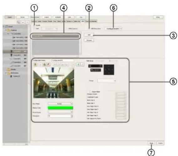
For details on each of the items, refer to "Setting Items of [VMD] Tab (VMD (Recorder))" (page 60).
①Select the [Enable] check box.
②Select [VMD (Recorder)].
③Click [Add]. An area configuration is added.
④Select the area configuration to configure.
⑤Create and edit the motion detection area while checking the preview.
⑥Select the configuration to use as the standard area configuration.
The standard area configuration is used for monitoring, manual recording, and the like at times other than for alarm recording schedules.
⑦Click [Apply].
The motion detection area is configured, and the VMD (recorder) pin is added to the [Device].
Setting Items of [VMD] Tab (VMD (Recorder))
This tab is displayed by clicking [Device] in the [Configuration] window, and selecting [VMD (Recorder)] on the VMD tab.
After changing the settings, click [Apply] to save your settings.
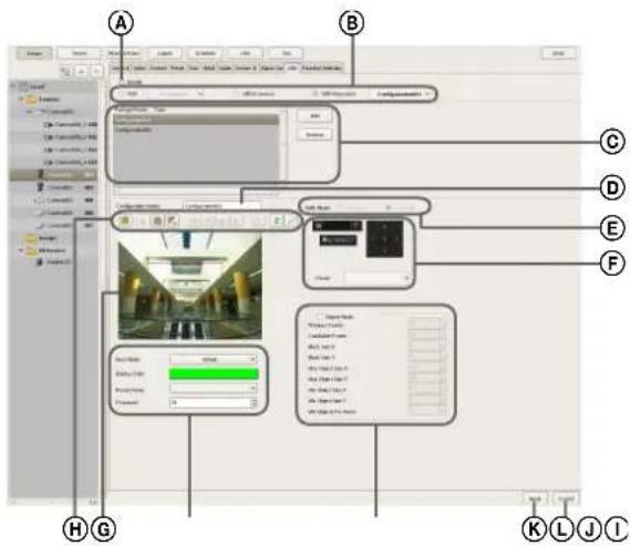
ⒶEnable
Select the check box to enable the motion detection function.
⑧Type of Motion Detection Function
Select [VMD (Recorder)] here.
The following setting items differ depending on the motion detection function that is selected here.
Select the area configuration to use as the standard area configuration in the drop-down menu.
The standard area configuration is used for monitoring, manual recording, and the like at times other than for alarm recording schedules.
©Area Configuration List
This displays a list of the area configurations that are configured for this camera.
Add
This adds a new configuration.
Delete
This deletes the selected configuration.
Configuration Name
Enter a name for the area configuration.
The name you enter here is used when configuring an alarm recording schedule to be triggered by movement in the motion detection area.
E VMD Mode
Select the Advanced mode or Standard mode.
Always verify your operating environment first, because performance may vary depending on the mode.
- The Standard mode can perform motion detection simultaneously with more cameras than the Advanced mode.
- The Advanced mode offers better detection accuracy.
- Note that when the VMD mode is changed, the default values for [Previous Frame] and [Candidate Frame] are configured for each mode.
- When the codec is MPEG4, only the Advanced mode is supported.
Caution
When the codec for cameras set to the Standard mode is changed to MPEG, the VMD mode is switched automatically to the Advanced mode. In addition, [Previous Frame] and [Candidate Frame] are set to the default values for the Advanced mode.
©Image Controls
These control the images displayed in the preview area. The operating procedure is the same as that of the main screen. Refer to “Functions and Operating Procedure of Main Screen” (page 107).
©Preview
This displays live images or recorded images.
©Tool Buttons
Create and edit the motion detection area while checking the image in the preview.

(Move Polygon)
Use this button to create a rectangular mask or move a mask by dragging with the mouse.

(Edit Point)
Use this button to add/delete points and to create masks of complex shapes.

(Add Point)
Use this button to divide a line at a specific location. You can also add an edit point to a mask by clicking a line while holding down the Ctrl key.

(Remove Point)
Use this button to decrease the number of lines by one. You can also remove an edit point from a mask by clicking an edit point while holding down the Ctrl key.

(Bring to Front)
Use this button to move the selected mask to the top of a stack of overlapping masks.

(Bring Forward)
Use this button to move the selected mask up one level in a stack of overlapping masks.

(Send Backward)
Use this button to move the selected mask down one level in a stack of overlapping masks.

(Send to Back)
Use this button to move the selected mask to the bottom of a stack of overlapping masks.

(Remove Polygon)
Use this button to delete the selected mask.

(Refresh Image)
Use this button to refresh the still image that includes all the masks.

(Preview)
Use this button to displays a live image from the camera that includes the video motion detection masks. This allows you to confirm how the configured areas appear.
①Area Mode
Select whether to detect motion inside or outside the configuration area.
To detect motion inside the configuration area, select [Include], and to detect motion everywhere outside the configuration area, select [Exclude].
Display Color
Click the box, and select a fill color for the motion detection mask in the dialog box that appears.
Preset Name
If this setting is configured, the camera moves to the specified preset position when motion is detected in the specified area.
Threshold
Set a value from 1 to 100 as the sensitivity level for motion detection. The motion detection processor uses this value as the standard value for determining whether motion has occurred between frames.
①Expert Mode
Select the check box to configure advanced settings for the area.
If this check box is selected, the following items can be configured.
Previous Frame
Specify, the number of frames for the number of images to compare as a basis for determining that an object has moved.
Using the specified frames, NSR delegates frames as candidates for detection and performs noise reduction.
Caution
Setting this number high facilitates noise reduction, but processing speed decreases as a result of the increase in the processing load.
Candidate Frame
Based on this value, NSR configures the number of times a determination needs to be made for a candidate image to be detected as moving.
Block Size X
Specify the horizontal length of the detection area in pixels.
Block Size Y
Specify the vertical length of the detection area in pixels.
Max Object Size X
Specify the maximum horizontal length of the object as a percentage.
Max Object Size Y
Specify the maximum vertical length of the object as a percentage.
Min Object Size X
Specify the minimum horizontal length of the object as a percentage.
Min Object Size Y
Specify the minimum vertical length of the object as a percentage.
Min Objects For Alarm
Specify the minimum number of detected objects for sending notification of an alarm.
©Apply
This saves the settings.
LCancel
This cancels the changes to the settings.
Using the Motion Detection Function of the Camera (VMD (Camera))
To use the motion and object detection functions by camera (VMD (camera)), use the procedure below to configure the VMD (camera) pin, and motion detection and object detection areas.
The setting items for the motion detection and object detection areas differ depending on the camera you are using.
1 Click [Device] at the top of the Configuration window.
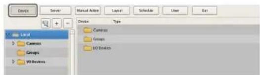
The Device Configuration screen appears.
2 Configure each item on the [VMD] tab, and configure the motion detection area.
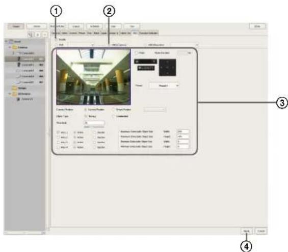
For details on each of the items, refer to "Setting Items of [VMD] Tab (VMD (Camera))" (page 63).
①Select the [Enable] check box.
②Select [VMD (Camera)].
③Configure the motion detection area while checking the preview.
④Click [Apply].
The motion detection area is configured.
Setting Items of [VMD] Tab (VMD (Camera))
This tab is displayed by clicking [Device] in the [Configuration] window, and selecting [VMD (Camera)] on the VMD tab.
After changing the settings, click [Apply] to save your settings.
Note
The setting items Ⓖ differ depending on the camera you are using.
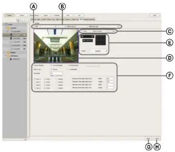
ⒶEnable
Select the check box to enable the motion detection function.
⑧Type of Motion Detection Function
Select [VMD (Camera)] here.
The following setting items differ depending on the motion detection function that is selected here.
©Pulse
Select the check box when you wish to specify a pulse duration and input a pulse.
If you select this, enter a value for [Pulse Duration].
Pulse Duration
Enter the duration in milliseconds to sustain pulse input from the VMD (camera) pin once it is turned on.
©Preview
This displays the images from the camera.
Use the following procedure to create an area for detecting motion.
- Click and drag the mouse over the image to create a motion detection area (red frame).
By dragging each edge of the area, you can change the size of the area. - Enter pixel values in the [Active Area] boxes to set the motion detection area.
E
For a camera equipped with pan, tilt, and zoom functions, use this to change the direction and zoom of the camera when configuring an area.
⑤Camera Position
Select the camera position to configure.
Current Position
Select this option when configuring the settings for the current camera position.
Preset Position
Select this option when configuring settings for each preset.
If you select this, select a preset from the drop-down menu, and move the camera to that preset position.
When the camera is moved to the preset position you specified, the settings for that position are enabled.
The settings for one preset position cannot be used for another preset position.
Object Type
Select [Moving] or [Unattended].
The following items differ for [Moving] and [Unattended]. You can only configure one of [Moving] and [Unattended] within each screen.
- When Moving:
Threshold
Enter a value for the threshold for motion detection.
- When Unattended:
Detection Time
Enter from 40 to 43200 (seconds) for the time from when an object stops moving until the object is detected as unattended and an alarm is triggered.
The countdown is reset if the object starts moving again during the specified duration.
Caution
After an unattended object is detected (after the alarm occurs), another unattended object may not be detected for up to one minute.
Area 1 to Area 4
Select Active or Inactive for each detection area.
Minimum Detectable Object Size
Enter a minimum size for the object to be detected.
Alternatively, configure the size by using the mouse to drag the minimum detectable object size setting frame (light blue). You can change the size by dragging each of the edges. The setting frame cannot be deleted.
Maximum Detectable Object Size
Enter a maximum size for the object to be detected. Alternatively, configure the size by using the mouse to drag the maximum detectable object size setting frame (blue). You can change the size by dragging each of the edges. The setting frame cannot be deleted.
©Apply
This saves the settings.
HCancel
This cancels the changes to the settings.
Detecting Motion by Metadata (VMF)
If the camera supports motion detection metadata, configure settings related to the VMF (Video Motion Filter) to use for motion detection by metadata. VMF is a filter for detecting specific motion phenomena from motion-related metadata generated within the camera.
There are VMFs for motion and object detection, and up to three VMFs can be managed together as one VMF package. The filters in a VMF package can be combined either sequentially, whereby each filter must be satisfied in sequential order to trigger an alarm, or in parallel, whereby satisfying any one filter is sufficient to trigger an alarm.
Overview of Motion Detection by Camera Image Metadata
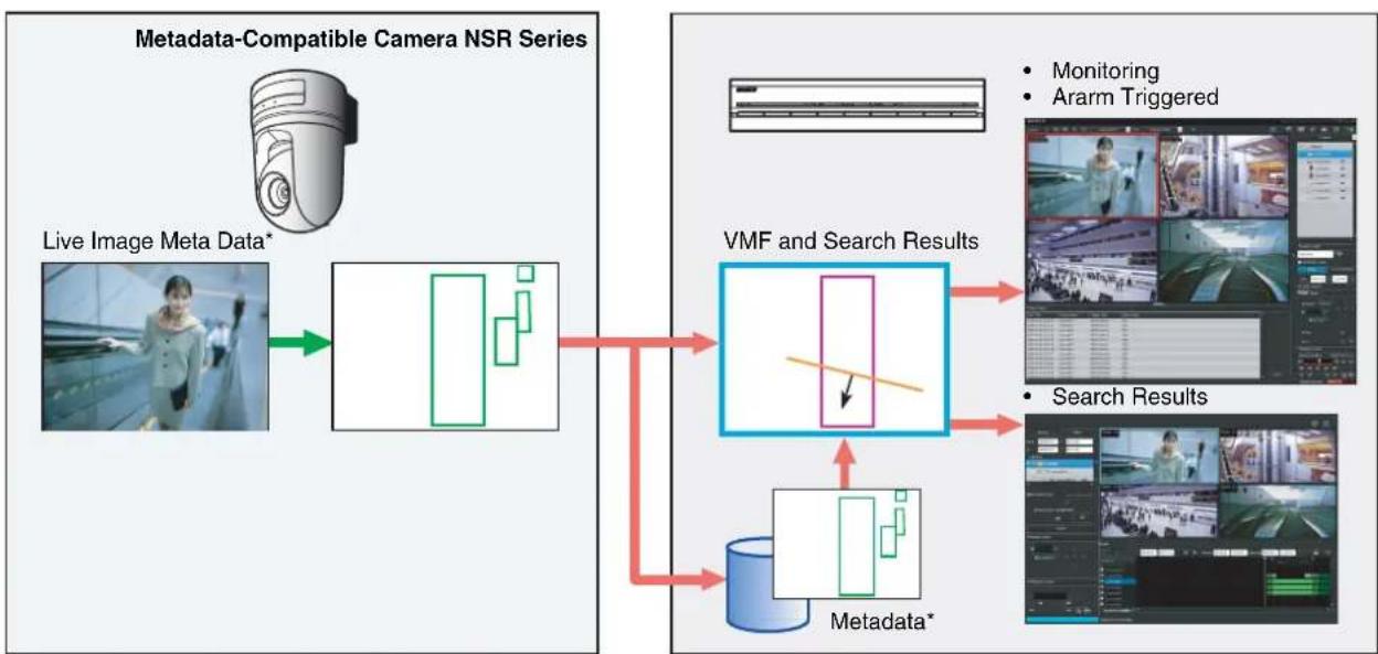
flowchart
graph TD
    A["Live Image Meta Data*"] --> B["Image 1"]
    B --> C["VMF and Search Results"]
    C --> D["VMF and Search Results"]
    D --> E["VMF and Search Results"]
    E --> F["VMF and Search Results"]
    F --> G["VMF and Search Results"]
    G --> H["VMF and Search Results"]
    H --> I["VMF and Search Results"]
    I --> J["VMF and Search Results"]
    J --> K["VMF and Search Results"]
    K --> L["VMF and Search Results"]
    L --> M["VMF and Search Results"]
    M --> N["VMF and Search Results"]
    N --> O["VMF and Search Results"]
    O --> P["VMF and Search Results"]
    P --> Q["VMF and Search Results"]
    Q --> R["VMF and Search Results"]
    R --> S["VMF and Search Results"]
    S --> T["VMF and Search Results"]
    T --> U["VMF and Search Results"]
    U --> V["VMF and Search Results"]
    V --> W["VMF and Search Results"]
    W --> X["VMF and Search Results"]
    X --> Y["VMF and Search Results"]
    Y --> Z["VMF and Search Results"]
    Z --> AA["VMF and Search Results"]
    AA --> AB["VMF and Search Results"]
    AB --> AC["VMF and Search Results"]
    AC --> AD["VMF and Search Results"]
    AD --> AE["VMF and Search Results"]
    AE --> AF["VMF and Search Results"]
    AF --> AG["VMF and Search Results"]
    AG --> AH["VMF and Search Results"]
    AH --> AI["VMF and Search Results"]
    AI --> AJ["VMF and Search Results"]
    AJ --> AK["VMF and Search Results"]
    AK --> AL["VMF and Search Results"]
    AL --> AM["VMF and Search Results"]
    AM --> AN["VMF and Search Results"]
    AN --> AO["VMF and Search Results"]
    AO --> AP["VMF and Search Results"]
    AP --> AQ["VMF and Search Results"]
    AQ --> AR["VMF and Search Results"]
    AR --> AS["VMF and Search Results"]
    AS --> AT["VMF and Search Results"]
    AT --> AU["VMF and Search Results"]
    AU --> AV["VMF and Search Results"]
    AV --> AW["VMF and Search Results"]
    AW --> AX["VMF and Search Results"]
    AX --> AY["VMF and Search Results"]
    AY --> AZ["VMF and Search Results"]
    AZ --> BA["VMF and Search Results"]
    BA --> BB["VMF and Search Results"]
    BB --> BC["VMF and Search Results"]
    BC --> BD["VMF and Search Results"]
    BD --> BE["VMF and Search Results"]
    BE --> BF["VMF and Search Results"]
    BF --> BG["VMF and Search Results"]
    BG --> BH["VMF and Search Results"]
    BH --> BI["VMF and Search Results"]
    BI --> BJ["VMF and Search Results"]
    BJ --> BK["VMF and Search Results"]
    BK --> BL["VMF and Search Results"]
    BL --> BM["VMF and Search Results"]
    BM --> BN["VMF and Search Results"]
    BN --> BO["VMF and Search Results"]
    BO --> BP["VMF and Search Results"]
    BP --> BQ["VMF and Search Results"]
    BQ --> BR["VMF and Search Results"]
    BR --> BS["VMF and Search Results"]
    BS --> BT["VMF and Search Results"]
    BT --> BU["VMF and Search Results"]
    BU --> BV["VMF and Search Results"]
    BV --> BW["VMF and Search Results"]
    BW --> BX["VMF and Search Results"]
    BX --> BY["VMF and Search Results"]
    BY --> BZ["VMF and Search Results"]
* Metadata includes time and camera information, and location, type, and status of motion.
Notes
• To perform motion detection and object detection using metadata, a camera that supports motion detection by metadata is required.
- When using VMF motion detection with the [Existing] filter type, the alarm state is maintained after object detection for as long as the object continues to be present. As a result, if a second alarm is triggered in this state, alarm recording will not start. When you want NSR to record the second alarm, select [Event Start] in the schedule settings (page 84). This ensures that everything is recorded during the alarm period, including the second alarm.
- When object detection metadata is processed, the object detection status is maintained for approximately three hours after detection, but the VMF detection status is cleared after approximately ten seconds.
- A VMF package can only process the live camera image of one camera at a time.
- When metadata is recorded, either motion detection metadata or object detection metadata is selected, based on the VMF being applied at the time. The order of priority is determined as follows:
①If something has been specified in the alarm recording schedule, priority is determined by whether the VMF package is for motion detection or object detection.
②If a VMF package is not specified, priority is determined based on the default package.
③If a default package is not specified either, the metadata is recorded as motion detection metadata.
Caution
Object detection requires an approximately 40 second initialization period before starting. Also, moving objects that have remained still for approximately 40 seconds are regarded as unattended. These times may be extended depending on the circumstances.

1 Click [Device] at the top of the Configuration window.
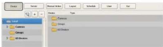
The Device Configuration screen appears.
2 Select the camera that will be the target for processing from the [Device] tree.
3 Add the VMF package.
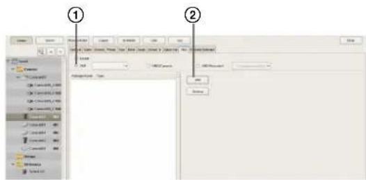
①Select the [VMF] check box.
②Click [Add], select whether to add a motion package or object package from the Select Package Type dialog box that appears, and click [OK].
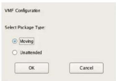
The package is added.
4 Configure each item, and configure the VMF package.
A VMF package consists of a combination of up to three filters (motion detection criteria), with advanced settings for each filter, and up to six inactive areas. Follow the procedure below to configure filters and inactive areas.
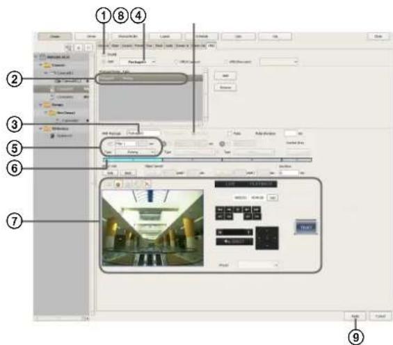
For details on each of the items, refer to "Setting Items of [VMD] Tab (VMF)" (page 67).
①Select the [Enable] check box.
②Select the package to configure.
③Change the package name, as necessary.
④Select how the filters are combined ([Sequential] or [Parallel]).
Note
For sequential configurations, be sure to configure two or more filters.
Caution
To switch between sequential and parallel, the button for each filter and inactive area must be turned off. When a button is (On), click to set it to (Off).
⑤Set the filter name and filter type.
⑥Click to set the button to (On) When the button is (On), the criteria can be set.
⑦Configure the criteria while checking the preview. Repeat Steps ⑤ to ⑦ to configure the remaining filters and inactive areas in the same way.
⑧Select the package to use as the default package. The default package is used for monitoring, manual recording, and the like at times other than for alarm recording schedules by VMF.
⑨Click [Apply].
Setting Items of [VMD] Tab (VMF)
This tab is displayed by clicking [Device] in the [Configuration] window, and selecting [VMF] on the VMD tab.
After changing the settings, click [Apply] to save your settings.
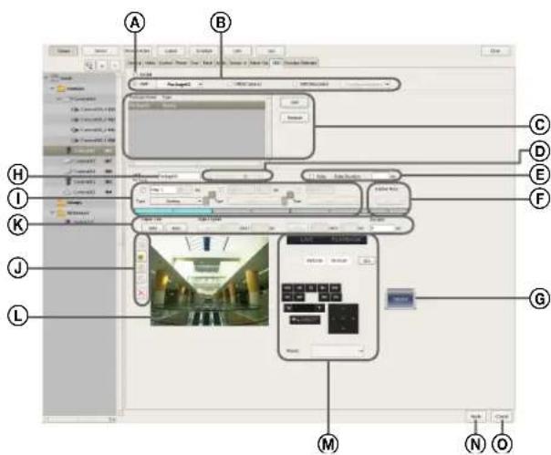
ⒶEnable
Select the check box to enable the motion detection function.
⑧Type of Motion Detection Function
Select [VMF] here.
The following setting items differ depending on the motion detection function that is selected here.
In the drop-down menu, select the package to use as the default package.
The default package is used for monitoring, manual recording, and the like at times other than for alarm recording schedules by VMF.
©VMF Package List
This displays a list of the VMF packages configured for this camera.
Add
This displays the Select Package Type dialog box for adding a new VMF package.
Delete
This deletes the selected VMF package.
DSequential
Select this option to detect specific phenomena by applying the filters in sequential order.
The filters are applied sequentially from the left. When this option is selected, you can set the time and sequence in which to apply the filters.
[Sequential] cannot be specified when setting an object detection package.
Parallel
Select this option to detect specific phenomena by applying all detection criteria simultaneously.
Caution
To switch between sequential and parallel, the

button for each filter and
inactive area must be turned off
. When a button is

(On), click to set it to
(Off).
©Pulse
Select the check box when you wish to specify a pulse duration and input a pulse.
If you select this, enter a value for [Pulse Duration].
Pulse Duration
Enter the duration in milliseconds to sustain pulse input from the VMD (camera) pin once it is turned on.
⑤Inactive Area Frame
Configure the inactive area frame.


Set the button to (On), and
create an inactive area in the area of Ⓛ.
Clicking the button switches it between

(On) and
(Off).
© (Preview)
Click this button to confirm the operation of the filtering used in the configured package.
⑧Package Name
Enter a name for the package.


Select the check box in front of the filter name to enable the filter.
You can change the filter name, as necessary.
Type
Select the filter type.
The filters that can be set differ depending on the package type (“Moving” or “Unattended”).
■For "Moving" packages
Appearance
This detects the appearance of objects that match the detection criteria within the configured area.
Disappearance
This detects the disappearance of objects that match the detection criteria within the configured area.
Existing
This detects when objects that match the detection criteria remain within the configured area.
Capacity
This detects when the number of objects that match the detection criteria has exceeded the specified number within the configured area.
Passing
This detects when objects that match the detection criteria cross a configured line.
■For "Unattended" packages
Unattended/Removed
This detects non-motion or when an object has been removed.
Duration
When [Sequential] is selected, this option allows you to enter in seconds the duration to apply the filter on the left (before moving to the next filter).
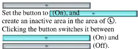

This switches the order of the filters on the left and right.
①Tool Buttons
Create and edit the filter and inactive area while checking the image in the preview.
Notes
- Up to eight vertices can be set for a convex polygonal area.
- When the filter type is set to [Passing], set the direction along which to detect the object's passing. After setting the end points, click near the center of the line to set the arrow indicating the direction of passage. With each click, the orientation of the arrow changes as follows: both directions right direction left direction both directions...

(Move Polygon)
Use this button to create a rectangular mask or move a mask by dragging with the mouse.

(Edit Point)
Use this button to add/delete points and to create masks of complex shapes.

(Add Point)
Use this button to divide a line at a specific location. You can also add an edit point to a mask by clicking a line while holding down the Ctrl key.

(Remove Point)
Use this button to decrease the number of lines by one. You can also remove an edit point from a mask by clicking an edit point while holding down the Ctrl key.

(Remove Polygon)
Use this button to delete the selected mask.
©Object Size
Set the size for the object to be detected.
MIN
This sets a minimum size for the object to be detected. Drag the light blue frame that appears on the configuration screen with your mouse to change the size of the frame.
MAX
This sets a maximum size for the object to be detected. Drag the blue frame that appears on the configuration screen with your mouse to change the size of the frame.
Object Speed
Set the speed for the object to be detected.

Click [MIN], and enter a minimum speed for the object to be detected.
When you draw a line segment on the configuration screen by dragging the mouse, a value is entered in the [pixel] box. Set how many seconds it should take to move that distance.
In the default state, the minimum speed is set to the minimum value for the system.
To return the value to the minimum value once the setting has been changed, click the figure that indicates the speed, and then click [MIN].

Click [MAX], and enter a maximum speed for the object to be detected.
When you draw a line segment on the configuration screen by dragging the mouse, a value is entered in the [pixel] box. Set how many seconds it should take to move that distance.
In the default state, the maximum speed is set to the maximum value for the system.
To return the value to the maximum value once the setting has been changed, click the figure that indicates the speed, and then click [MAX].
■Duration (When [Existing] and [Unattended/Removed] Filter Types)
When using the [Existing] filter type, enter the amount of time for NSR to wait before triggering an alarm, after an object is detected as moving. The default value is 0.
When using the [Unattended/Removed] filter type, enter the amount of time for NSR to wait before triggering an alarm, after an object is detected as unattended.
Notes
- Object detection requires approximately 40 seconds to initialize before starting.
- When an object is detected as unattended, its non-motion status is maintained and the detection frame continues to be displayed for about 3 hours.
■Capacity (When [Capacity] Filter Type)
Enter the maximum number of objects that can be detected in the configured area before an alarm is triggered.
■Collision (When [Passing] Filter Type)
Select the object's center of gravity, or which side of the object will trigger an alarm when it crosses the configured line.
LPreview
This displays live images or recorded images.
©Image Controls
These control the images displayed in the preview area. The operating procedure is the same as that of the main screen. Refer to “Functions and Operating Procedure of Main Screen” (page 107).
®Apply
This saves the settings.
©Cancel
This cancels the changes to the settings.
Configuring Settings Related to Storage
You can configure settings for storage in the storage location for image data and audio data of cameras.
You can configure up to 32 storage items, and configure settings such as the maximum size of the recording file for each storage item.
In addition, there are the following modes for storage, and you can classify and save recording data.
• [Record Type] Mode
You can specify storage for each recording type, such as schedule recording and alarm recording.
• [Camera] Mode
You can specify storage for saving recording data for each camera.
Configuring Storage Settings
Add new storage, and specify the recording data to save to the storage.
Storage can be added as individual logical volumes.
Adding New Storage
1 Click [Server] at the top of the Configuration window.
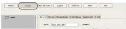
The Server Configuration screen appears.
2 Select the server for which you want to set the storage from the [Server] tree on the left of the screen.
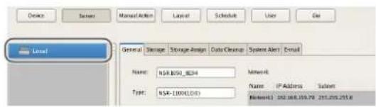
3 Click (Add Storage) on the right of the list on the [Storage] Tab.
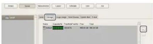
The Add Storage dialog box appears.
4 Select the location to add as storage, and click [OK].
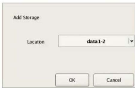
The storage is added to the list.
5 Configure each item, and click [Apply].
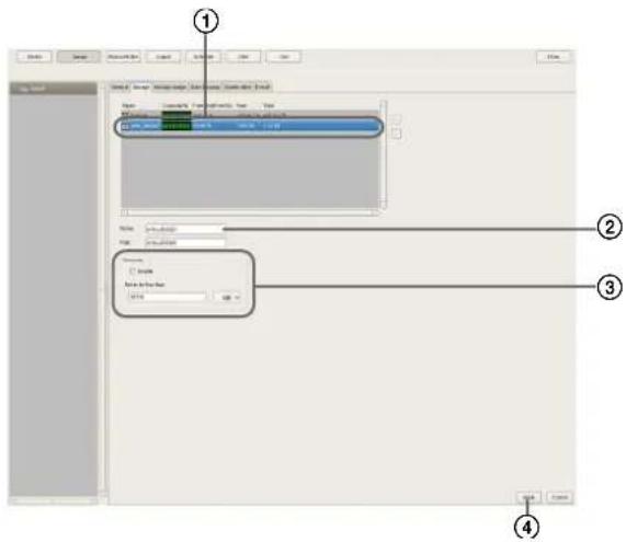
For details on each of the items, refer to "Setting Items of the [Storage] Tab" (page 71).
①Select the configured storage.
②Enter a name for the storage.
③Configure the settings related to overwriting data, as necessary.
④Click [Apply]. The storage is added.
Configuring Storage for Each Recording Type ([Record Type] Mode)
You can specify storage for each recording type, such as manual recording, schedule recording, and alarm recording.
1 Select the server for which you want to configure storage from the [Server] tree, and click the [Storage Assign] tab.
2 Configure each item, and click [Apply].
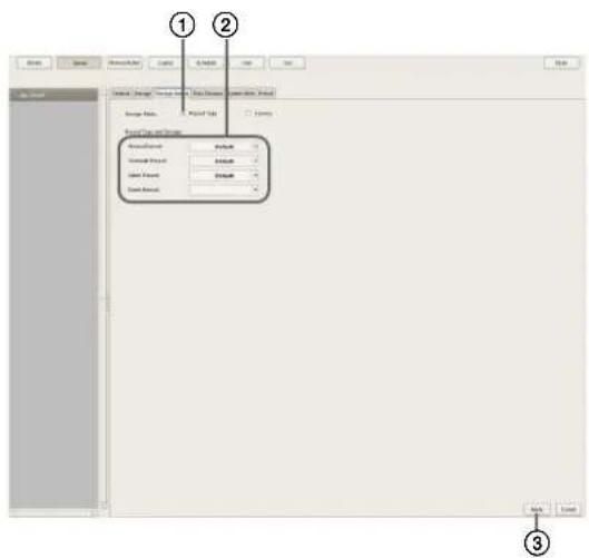
For details on each of the items, refer to "Setting Items of [Storage Assign] Tab" (page 72).
①Select [Record Type].
②Select storage for each recording type.
③Click [Apply].
Storage is set for each recording data.
Configuring Storage for Each Camera ([Camera] Mode)
You can specify storage for saving recording data for each camera.
It is possible to save all recording data to one storage, and specify storage for saving for each recording type.
1 Select the server for which you want to configure storage from the [Server] tree, and click the [Storage Assign] tab.
2 Configure each item, and click [Apply].
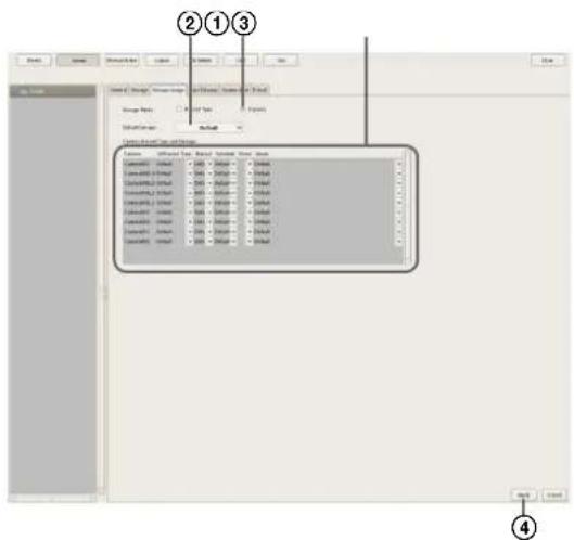
For details on each of the items, refer to “Setting Items of [Storage Assign] Tab” (page 72).
①Select [Record Type].
②Select the default storage.
③Select storage for each camera.
④Click [Apply]. Storage is set for each recording data.
Setting Items of the [Storage] Tab
This tab is displayed by clicking [Server] in the [Configuration] window, and clicking the [Storage] tab. After configuring each item, click [Apply].
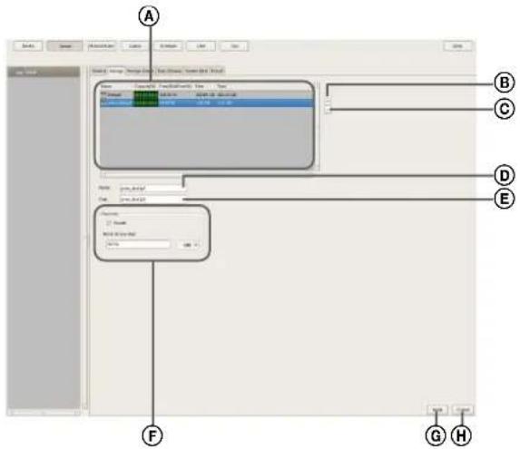
![SONY NSR1100 - Setting Items of the [Storage] Tab - 2](/content/2026/05/859819/images/13162d3f297dc0d0390910b18288635ca804780d324b0da77eb1581461c4ac7e.jpg)
ⒶStorage List
This displays a list of the storage configured for the server selected in the [Server] tree.
Name
This displays the name of the storage.
Capacity
This displays the capacity of the storage.
Free (%)
This displays the amount of free space as a percentage.
Free
This displays the amount of free space.
Total
This displays the total size of this storage.
B (Add Storage)
This adds new storage.
© (Delete Storage)
This deletes the storage selected in the list.
Caution
If you delete storage, all of the internal data will be lost.
DName
Enter a name for the storage selected in the list.
©Location
This displays a location (path) for saving the recording data.
This item cannot be changed.
©Overwrite
Set this option to delete data from the oldest, regardless of how many days it has been stored, to ensure storage space is available.
Enable
Select the check box to enable the data overwrite function.
The data is deleted automatically beginning with files within the oldest record whenever the amount of free space of the storage will fall below a specified size.
Not to be less than
Enter the minimum limit for free space as a percentage or in gigabytes.
©Apply
This saves the settings.
HCancel
This cancels the changes to the settings.
Setting Items of [Storage Assign] Tab
This tab is displayed by clicking [Server] in the [Configuration] window, and clicking the [Storage Assign] tab.
After configuring each item, click [Apply].
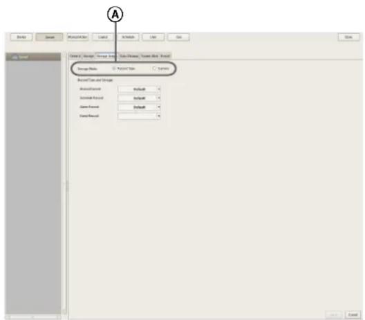
ⒶStorage Mode
Select the method for specifying recording data for saving to storage.
The setting items vary depending on this selection.
Record Type
Select this to specify storage for each recording type, such as schedule recording and alarm recording.
Camera
Select this to specify storage for saving recording data for each camera.
■To assign storage for each recording type
⑧Record Type and Storage
Select storage for each recording type.
![File Edit View Insert Tools Help Name: [Drawing1-Form] Sub-Change, Series (End-End) Design Tools Add Type Delete Add/Remove Delete Add/Remove Delete Add/Remove Delete B C D](/content/2026/05/859819/images/08f9800f2d510bb24647680b70a223b4c1c827446f61cb961ca601a941fcd0b1.jpg)
Manual Record
Select storage for saving for manual recording.
Schedule Record
Select storage for saving for schedule recording.
Alarm Record
Select storage for saving for alarm recording.
Event Record
Select storage for saving for event recording.
©Apply
This saves the settings.
©Cancel
This cancels the changes to the settings.
■To assign storage for each camera
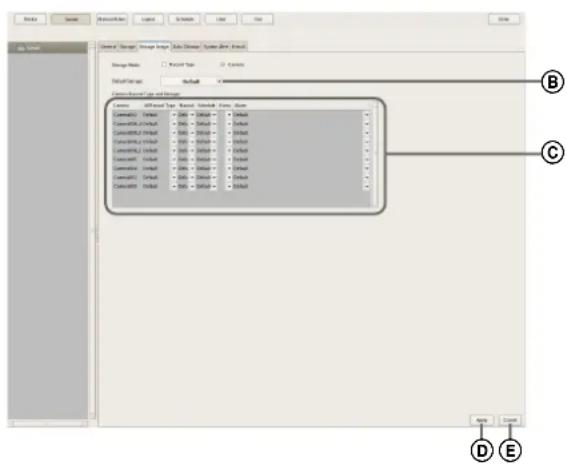
®Default Storage
Select the default save location for recording data.
©Storage for Each Camera and Record
Specify storage for each camera and recording type.
Camera
This displays a list of the cameras registered to NSR. This item cannot be changed.
All Record Type
Select storage for when recording the recording data of all recording types to one storage.
When specifying storage for each recording type, select [Select Each].
Manual Record
Select storage for saving for manual recording.
Schedule Record
Select storage for saving for schedule recording.
Alarm Record
Select storage for saving for alarm recording.
Event Record
Select storage for saving for event recording.
©Apply
This saves the settings.
ECancel
This cancels the changes to the settings.
Configuring Settings Related to Deleting Recording Data
There are the following methods for deleting recording data saved to storage.
• Data Overwriting (page 73)
Delete data from the oldest automatically, regardless of how many days it has been stored, to ensure storage space is always available.
- Cleanup (page 74)
Set the number of days to store recording data, and automatically delete data that exceeds that number of days.
- Deleting Manually (page 122)
Specify recording data for deletion manually.
Data Overwriting
Delete data from the oldest automatically, regardless of how many days it has been stored, to ensure storage space is always available. You can set overwriting for each recording location.
Caution
- Estimate enough storage space to record the images you want to save before you configure the minimum value.
- When the data overwrite function is enabled and a file currently being played back falls under the conditions for deletion, playback of that file stops and the file is deleted.
- If data overwriting is performed for the recording data of a normal recording, multiple files within one record will be deleted at one time, which may result in only the recording of a certain camera being deleted at one time. Configuring the following setting allows you to more uniformly delete the recording data of multiple cameras.
– In the recurrent schedule of the normal recording, insert at least a 1-second break each day.
Example: Start time: 00:00:00 End time: 23:59:59

1 Select the server for which you want to configure storage from the [Server] tree, and click the [Storage] tab.
2 Configure each item, and click [Apply].
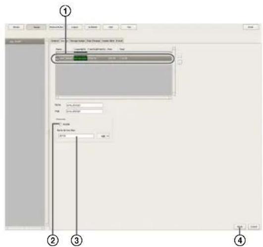
①Select the storage you want to configure.
②Select the [Enable] check box.
③Enter the minimum limit for free space as a percentage or in gigabytes.
④Click [Apply]. Overwriting is configured.
Cleanup
To ensure storage space is available, set the number of days to store recording data, and automatically delete data that exceeds that number of days. You can configure the same number of storage days for all cameras, or configure the settings separately for each camera.
1 Select the server for which you want to configure storage from the [Server] tree.
2 Configure each item on the [Data Cleanup] tab, and click [Apply].
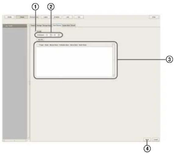
For details on each of the items, refer to "Setting Items of the [Data Cleanup] Tab" (page 75).
①Select the [Enable] check box.
②Configure the time for performing the cleanup.
③Select the check boxes of the cameras to be target for the cleanup, and configure the number of days to store each type of recording data.
To configure the same settings for all cameras, click [Input All] and configure the number of storage days in the Input All dialog box that appears.
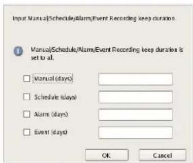
④Click [Apply].
The cleanup is configured.
Setting Items of the [Data Cleanup] Tab
This tab is displayed by clicking [Server] in the [Configuration] window, and clicking the [Data Cleanup] tab.
After configuring each item, click [Apply].
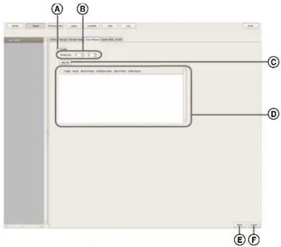
ⒶEnable
Select the check box to enable the cleanup function.
⑧Execution Time
Configure the time for executing the cleanup.
©Input All
Display the Input All dialog box for configuring the same settings for all cameras.
©Cleanup Setting List
This displays a list of the cleanup settings.
Target
Select the check boxes of the cameras to be the targets for the cleanup.
Camera
This displays a list of the names of the cameras registered to NSR.
Manual Record (days)
Enter the number of storage days for manual recording.
Schedule Record (days)
Enter the number of storage days for schedule recording.
Alarm Record (days)
Enter the number of storage days for alarm recording.
Event Record (days)
Enter the number of storage days for event recording.
©Apply
This saves the settings.
⑤Cancel
This cancels the changes to the settings.
Storage Configuration Example
You can also configure another partition of NSR or NSRES200 as storage.
1 Click [Administration Menu] on the [Login] screen.
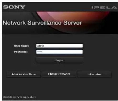
The Administration Menu screen appears.
2 Click [Setup Menu].
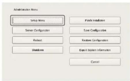
The Setup Menu appears.
3 Select [Disk], and click [Select].
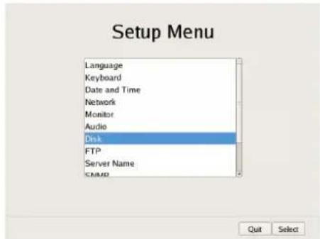
The Disk Menu screen appears.
4 Select [Install], and click [Select].
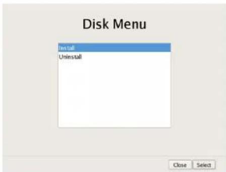
The Disk Installation screen appears.
5 Select the device to configure as storage, and click [Select].
Select [Internal Disk] for the internal hard disk, and [SAS Disk] for NSRE-S200.
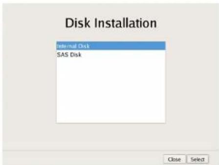
The screen for configuring partitions appears.
6 Configure each item.
Screen example: When internal hard disk Specify the number of partitions, select the size to allocate each partition as a percentage, and click [OK].
![Internal Disk Partition Volume Number: 1 Capacity: 443 GB Number of Partitions 3 Partition1 [data1-1] 10% 443 GB Partition2 [data1-2] 10% 44 GB Partition3 [data1-3] 10% 44 GB Partition4 [data1-4] 0 GB Total: 120 % Cancel OK](/content/2026/05/859819/images/a7b018aaca5587b772b3ff2b4b4a1a1cbf4e1d88c878e8b77e1b3be8ed82aa9f.jpg)
Screen example: When NSRE-S200
①Select the NSRE-S200 you want to configure, and click [Partition].
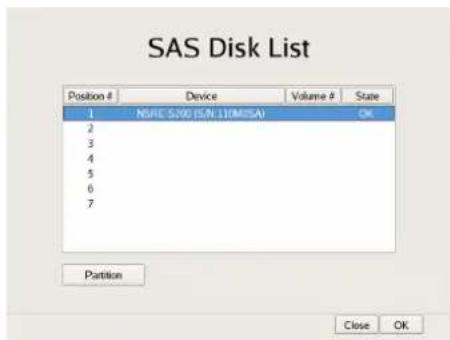
Caution
When an NSRE-S200 is connected, use a UPS.
②Specify the number of partitions, select the size to allocate each partition as a percentage, and click [OK].
![SAS Disk Partition Device: NSRE-S200 (S/N-110M0SA) Volume Number: 2 Capacity: 1360 GB Number of Partitions 2 Partition1 [data2-1] 60% 816 GB Partition2 [data2-2] 40% 544 GB Partition3 [data2-3] 0 GB Partition4 [data2-4] 0 GB Total: 100% Cancel OK](/content/2026/05/859819/images/2f1e03ca4366d6997e06e53f3793dd72bb090996e9e278de64c43215d7831cef.jpg)
The newly created partitions and added NSRE-S200 become available as storage.
7 Refer to "Configuring Storage Settings" (page 70), and configure the storage.
Configuring Recording Schedules
You can configure a recording schedule for each camera or group to perform recording at regular intervals, and start recording when an alarm or event occurs.
There are the following types of schedule.
- Schedule Recording (Normal Recording)
This records images from cameras at regular intervals according to the set schedule.
- Alarm Recording
This begins recording only when an alarm occurs within the time set for the schedule.
- Event Recording
This begins recording only when an event occurs within the time set for the schedule.
You can use the following procedures to configuring schedules.
- Configuring Schedules with Automatic Camera Registration (page 77)
Configure an automatic recording schedule with conditions that have been provided in advance.
- Configuring Schedules Manually (page 79)
You can manually configure the durations for performing schedule recording, alarm recording, and event recording. The duration setting methods are “recurrent schedule,” which allows you to repeat schedules weekly, and “date & time schedule,” which allows you to specify specific dates and times to run schedules.
- Configuring Alarm Recording/Event Recording (page 81)
You can configure an alarm recording/event recording to begin recording only when an alarm or event occurs within the duration configured for the schedule.
Caution
Before you set alarm recording or event recording, configure the inputs that will be the alarm triggers and the motion detection function. For the setting procedure, refer to “Configuring Motion Detection Settings” (page 59) and “Configuring Sensor Inputs” (page 86).
Record Segmenting in Continuous Long-term Recording
When you record continuously over a long period (such as from 00:00 to 24:00 every day for a long time), the number of configuration files for a record may exceed 10,000^1 . When this happens, the record is segmented, and subsequent data is recorded as a new record. If a record is
segmented, it will be displayed as a different record in searches and the like.
1) The number 10,000 is the total number of files since recording started. It includes files that are deleted with the cleanup and data overwrite functions.
The time period segmented will differ depending on the frame rate and resolution.
Example:
| Conditions Codec: | JPEG | |
| Resolution: | VGA | |
| Frame rate: | 10 fps | |
| Image quality: | 50% | |
| Time until segmentation Approx. 19 days | ||
When recording continuously over long periods, we recommend segmenting the record by setting a recording schedule that inserts a 1-second recording break each day. For details, refer to “Configuring Schedules Manually” (page 79).
Configuring Schedules with Automatic Camera Registration
Configure an automatic recording schedule with the following conditions that have been provided in advance. Automatic camera registration allows you to configure automatic recording for schedule recording and alarm recording.
Note
If a schedule or alarm recording was configured with automatic camera registration, check whether it matches operation and finely adjust the device settings if necessary.
| Setting Sched | duled recording | Alarm recording |
| Image size Max | Maximum image size supported by the camera. | |
| Codec Codec | that supports the maximum image size. (If supported by both JPEG and MPEG4, MPEG4 is selected.) | |
| Frame rate JP | EG:Depends on storage duration for recorded data.MPEG4:Depends on bitrate. | JPEG: 10 fpsMPEG4: 10 fps |
| Quality 50% | Level 3 (cameras with 5 level settings)Level 5 (cameras with 10 level settings) | 80%Level 5 (cameras with 5 level settings)Level 8 (cameras with 10 level settings) |
| Bitrate Depends on storage duration for recorded data. | MPEG4: 1.5 Mbps | |
| Recording trigger | – VMD (Camera)VMD (Recorder)JPEG: Standard modeMPEG4: High-performance mode | |
| Data storage location | Not changed from existing configuration. | Not changed from existing configuration. |
| Audio Disabled | Disabled | |
| Data overwrite | Not changed from existing configuration. | Not changed from existing configuration. |
| Cleanup Deletes | es data that exceeds storage duration. ^1) | Not changed from existing configuration. |
1) Schedule recording settings are also located in the Server Configuration screen. Priority is given to the shortest period configured.
1 Click [Schedule] at the top of the Configuration window.
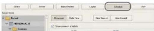
The Schedule Configuration screen appears.
2 Select the camera for which you want to configure a schedule from the tree on the left of the screen, and click [Auto Record].
You can also select multiple cameras at once by holding down the Shift key or Ctrl key while selecting.
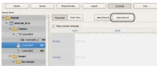
The Automatic Record Configuration dialog box appears.
3 Select [Automatic Schedule Record Configuration] to configure schedule recording or select [Automatic Alarm Record Configuration] to configure alarm recording, and click [Next].
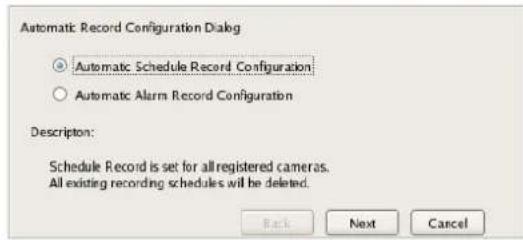
A confirmation message appears.
4 Click [Next].
Screen example: When [Automatic Schedule Record Configuration] is selected:
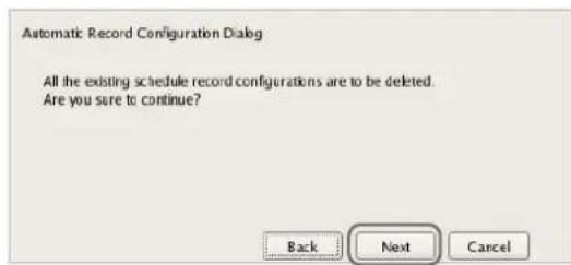
If you selected [Automatic Schedule Record Configuration], proceed to Step 5. If you selected [Automatic Alarm Record Configuration], proceed to Step 6.
5 Enter the number of days to store the recording data, and click [Next].
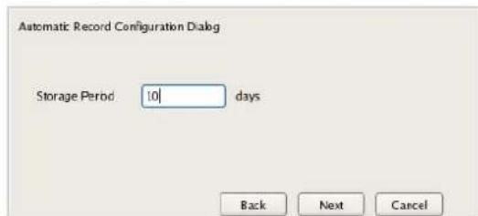
6 Check the displayed setting values, and click [Finish].
In the case of schedule recording, setting values corresponding to the storage period configured in Step 4 appear.
In the case of alarm recording, preset values appear.
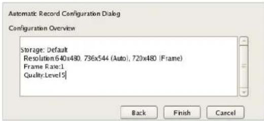
The automatic recording schedule is configured for all cameras.
You can confirm details of the configuration in the Schedule Configuration screen.
Configuring Schedules Manually
You can manually configure the durations for performing schedule recording, alarm recording, and event recording.
Note
For details on settings such as the codec and frame rate for images captured from the camera during schedule recording, alarm recording, or event recording, refer to "Configuring Camera Video Settings" (page 43).
Configuring Recurrent Schedules
You can configure a recurrent schedule to repeat a schedule weekly.
1 Select the camera or group for which you want to configure the schedule from the [Schedule] tree of the Schedule screen.
You can also select multiple cameras at once by holding down the Shift key or Ctrl key while selecting.
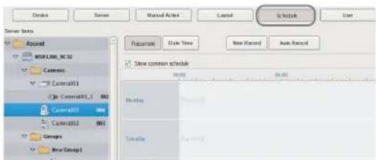
2 Click [Recurrent] to switch to recurrent view, and click [New Record].
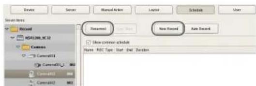
The New Record dialog box appears.
3 Configure each item, and click [OK].
The setting items differ depending on the type of schedule.
Screen example: When schedule recording
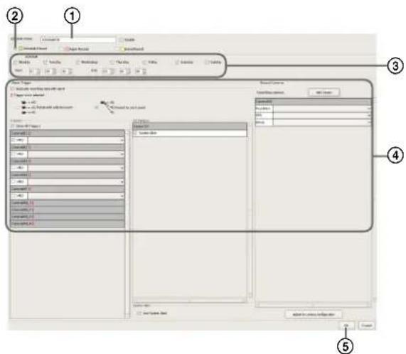
For details on each of the items, refer to "Setting Items of New Record Dialog Box" (page 84).
①Enter a name for the schedule.
②Select the type of schedule.
③Select the check boxes for the days you want to run the schedule, and configure a start time and end time for the schedule.
④Configure each item, as necessary. For details on the setting procedure for alarm recording and event recording, refer to "Configuring Alarm Recording and Event Recording" (page 81).
⑤Click [OK]. The schedule is created.
4 Click [Apply].
The schedule is saved.

For details on how to view the schedule, refer to "Setting Items of Schedule Screen" (page 83).
Configuring a Schedule for a Specific Date and Time
You can configure a schedule for a specific date and time to specify a date and time to run a schedule. The only difference from a recurrent schedule is the procedure for specifying a start and end date and time.
1 Select the camera or group for which you want to configure the schedule from the [Schedule] tree of the [Schedule] screen.
You can also select multiple cameras at once by holding down the Shift key or Ctrl key while selecting.
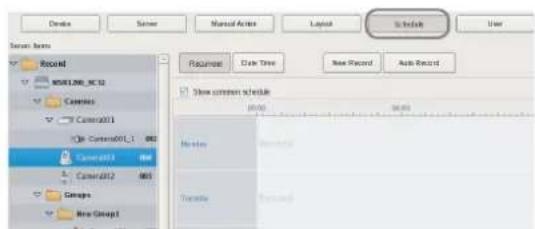
2 Click [Date Time] to switch to date and time view, and click [New Record].
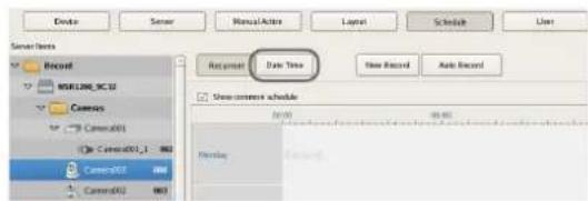
The New Record dialog box appears.
3 Configure each item, and click [OK].
The setting items differ depending on the type of schedule.
Screen example: When schedule recording
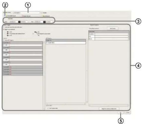
For details on each of the items, refer to "Setting Items of New Record Dialog Box" (page 84).
①Enter a name for the schedule.
②Select the type of schedule.
③Configure the start date and time and end date and time to apply the schedule.
④Configure each item, as necessary.
For details on the setting procedure for alarm recording and event recording, refer to "Configuring Alarm Recording and Event Recording" (page 81).
⑤Click [OK]. The schedule is created.
4 Click [Apply].
The schedule is saved.
For details on how to view the schedule, refer to “Setting Items of Schedule Screen” (page 83).
Configuring Alarm Recording and Event Recording
You can configure alarm recording or event recording to begin recording only when an alarm occurs within the time set for the schedule.
For details, refer to "About Relationship Between Sensor and Camera when Alarm Occurs" (page 82).
1 Select the camera or group for which you want to configure the schedule from the tree in the [Schedule] screen.
You can also select multiple cameras at once by holding down the Shift key or Ctrl key while selecting.
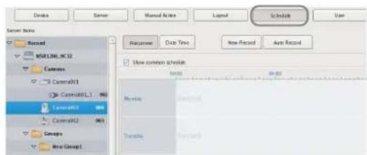
2 Click [Recurrent] or [Date Time] to switch to the view of the schedule you want to configure, and click [New Record].
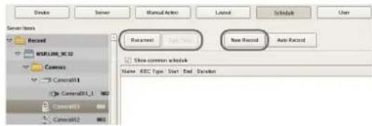
The New Record dialog box appears.
3 Configure each item, and click [OK].
The settings items differ depending on the type of schedule.
Screen Example: When alarm recording (recurrent schedule)
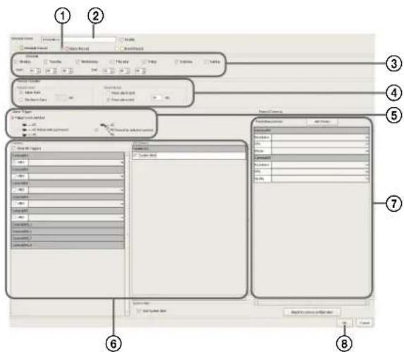
For details on each of the items, refer to "Setting Items of New Record Dialog Box" (page 84).
①Select [Alarm Record] or [Event Record].
②Enter a name for the schedule.
③Configure the days and time to run the schedule, or configure the period to run the schedule.
④Specify a condition to start recording and a condition to end recording, and configure the recording duration.
⑤In the case of alarm recording, select [Record by each event] or [Record by selected event].
- When [Record by each event] is selected, the input pin of the selected camera itself is the trigger to begin recording. - When [Record by selected event] is selected, all set input pins are triggers, and recording begins on all selected cameras.
For details, refer to "About Relationship Between Sensor and Camera when Alarm Occurs" (page 82).
⑥When [Record by each event] is selected, configure the input pin of the camera or I/O device that will be the trigger for alarm recording or event recording.
⑦Configure the camera to record images.
⑧Click [OK]. The schedule is created.
4 Click [Apply].
The schedule is saved.
For details on how to view the schedule, refer to "Setting Items of Schedule Screen" (page 83).

Changing Settings
1 Select the camera you want to change the settings of from the [Schedule] tree on the Schedule Configuration screen.
2 Switch to recurrent view or date view.
3 Select the time slot (recurrent view) or schedule (date view) for which you want to change the settings, and click [Edit].
The Schedule Configuration dialog box appears.
4 Reconfigure each item.
For details on each of the items, refer to "Setting Items of New Record Dialog Box" (page 84).
5 Click [Apply].
The settings are saved.
Deleting a Schedule
1 Select the schedule you want to delete from the [Schedule] tree on the Schedule Configuration screen.
2 Click [Remove].
A confirmation message appears.
3 Click [OK].
The schedule is deleted.
About Relationship Between Sensor and Camera when Alarm Occurs
When [Record by each event]:
The input pin of the selected camera itself triggers the beginning of recording.
For example, if camera A and camera B are selected as the cameras for recording images, and motion detection of camera A and sensor input of camera B are configured as the triggers, recording begins on camera A when motion detection occurs for camera A, and recording begins on camera B when sensor input turns on for camera B.
Recording begins on a camera whose input pin turns on.
![SONY NSR1100 - When [Record by each event]: - 1](/content/2026/05/859819/images/585adef31dd8302cc0df77563c29e4247f86224000a4fa7f53bef57ae4361098.jpg)
flowchart
graph LR
    A["Person with camera"] --> B["Camera"]
    C["Group of people"] --> D["Camera"]
    E["Person with monitor"] --> F["Camera"]
    G["Person with phone"] --> H["Camera"]
    I["Person with printer"] --> J["Camera"]
When [Record by selected event]:
All set input pins are configured as triggers to begin recording. Recording begins on all selected cameras regardless of which input pin turns on. For example, if camera A and camera B are selected as the cameras for recording images, and motion detection of camera A and sensor input of camera B are configured as the triggers, recording begins on both cameras even when motion detection occurs for camera A and even when sensor input turns on for camera B.
Recording begins on all selected cameras regardless of which input pin turns on.
![SONY NSR1100 - When [Record by selected event]: - 1](/content/2026/05/859819/images/d3d542e653a5fc400e6411683b5dfb126e6affe525311f7a12a726206f6948ba.jpg)
flowchart
graph TD
    A["air conditioner"] -->|NSR or or| B[" refrigerator"]
    A -->|NSR or or| C[" storage unit"]
    A -->|NSR or or| D[" database"]
    B -->|or| C
    B -->|or| D
    C -->|or| D
Setting Items of Schedule Screen
This screen is displayed by clicking [Schedule] in the Configuration window.
Screen example: When recurrent schedule (recurrent view)
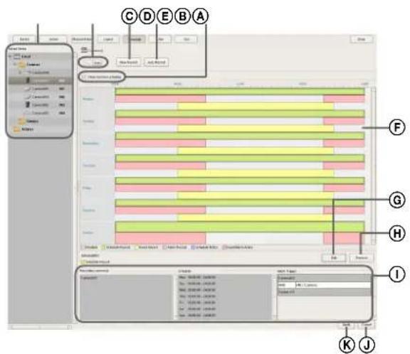
Ⓐ[Schedule] Tree
This displays a list of the configured cameras in a tree structure.
Selecting a schedule from the tree displays the setting details in the area on the right.
⑧Recurrent/Date and Time View Selection Button
Recurrent
Switches to recurrent view.
Date Time
Switches to date and time view.
©New Record
This displays the New Record dialog box (page 84) for creating a new schedule manually.
©Auto Record
This displays the Auto Record Configuration dialog box (page 78) for configuring an automatic recording schedule.
ECommon Schedule Display
Select the check box to display the schedules common to each of the cameras.
⑤Schedule View
This displays the details of the schedule.
When recurrent view:
In this view, schedule items are color-coded by action for each day of the week.
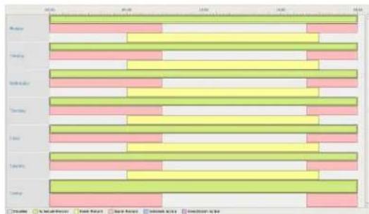
bar
| Category | Green Bar | Yellow Bar | Pink Bar | |---|---|---|---| | Monday | 10 | 8 | 6 | | Tuesday | 12 | 7 | 5 | | Wednesday | 13 | 6 | 4 | | Thursday | 14 | 5 | 3 | | Friday | 15 | 4 | 2 | | Saturday | 16 | 3 | 1 | | Sunday | 17 | 2 | 0 | | Sunday - Monday | 16 | 1 | 0 | | Sunday - Tuesday | 15 | 0 | 0 | | Sunday - Wednesday | 14 | 0 | 0 | | Sunday - Thursday | 13 | 0 | 0 | | Sunday - Friday | 12 | 0 | 0 | | Sunday - Saturday | 11 | 0 | 0 | | Sunday - Sunday | 10 | 0 | 0 | The chart displays the daily values for three categories: Green Bar, Yellow Bar, and Pink Bar. The values are displayed on the horizontal axis for each category. The data is presented in a grid format with 'Month' as the index of the month. There is no additional data series or trends visible in the image. The legend indicates the color coding: Green, Yellow, Pink. The chart is saved as a PNG file named 'box-and_1a.png'.- Guide lines are shown in 15-minute intervals, and by dragging the edges of each scheduled time slot, you can change the start and end times of the action. When you want to configure the time in detail, click [Edit] and make adjustments in the Schedule Configuration dialog box that appears.
- Selecting each time slot displays information such as the camera target for recording and the times for the duration in area ①.
When date and time view:
In this view, a list of the schedules that have been configured are displayed.
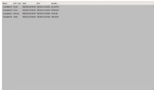
- Selecting each schedule displays information such as the camera target for recording and the times for the duration in area ①.
©Edit
This displays the Schedule Configuration dialog box for changing schedule settings.
⑧Remove
This deletes the selected schedule.
①Show Configuration Information
This displays the configuration information of the selected schedule.
①Apply
This saves the settings.
©Cancel
This cancels the changes to the settings.
Setting Items of New Record Dialog Box
This dialog box is displayed by clicking [New Record] on the Schedule screen (page 84).
The items that are displayed differ depending on the type of recording.
After configuring each item, click [OK].
Screen Example: When alarm recording (recurrent schedule)
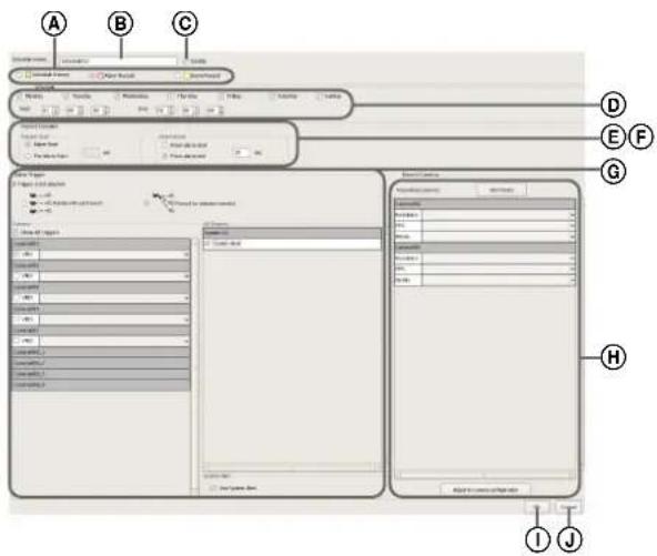
ⒶSchedule Record/Alarm Record/Event Record Select the type of schedule to configure.
BName
Enter the name of the schedule. It can be up to 32 characters long.
©Enable
Select the check box to enable this schedule.
DSchedule
The settings differ depending on whether you are configuring a recurrent schedule or a schedule for a specific date and time.
When recurrent schedule:
Select the check boxes for the days you want to run the schedule, and configure a start time and end time for the schedule.
The range that can be specified is 00:00:00 to 24:00:00 (hours/minutes/seconds).

When schedule for a specific date and time:
Configure the start date and time and end date and time to apply the schedule.

©Record Duration
This item is displayed in the case of alarm recording or event recording.
Set the record duration for when an event occurs.

Record Start
Select the timing for starting recording.
Event Start
This starts recording when an alarm or event started (point in time the alarm signal became active).
Pre Event Start
This goes back to record the images before an alarm or event started.
When this is selected, enter the period to go back to record within the range of 1 to 60 seconds.
Note
Pre alarm/event start recording cannot be performed for audio.
Record End
Select the timing for ending recording.
From Event Start
This ends recording at the point in time a specified period of time elapses after an alarm or event started (point in time the alarm signal became active).
When this is selected, enter the period for after the alarm or event starts within the range of 1 to 3,600 seconds.
From Even End
This ends recording when the specified duration has passed after the point in time the alarm or event ends (point in time the alarm is cancelled).
Note
If the camera properties for alarm recording or regular recording are different from the camera properties for monitoring, the camera image will stop updating for several seconds when recording starts and stops. Be sure to confirm your settings before operation.
⑤Associate recording data with alarm
This item is displayed for schedule recording.
Select the check box to associate the recording data with the alarm.
If you select the check box, configure the inputs of the camera or IO device that will be the trigger for the alarm.

Associate recording data with alarm
©Event
Select the relationship of the camera for recording and the sensor, and select the check box of the input to be the alarm trigger.
For details on the relationship of the camera and sensor, refer to “About Relationship Between Sensor and Camera when Alarm Occurs” (page 82).
Record by each event
The camera and sensor form a one-to-one relationship. Recording is started only for the camera of the sensor that detected the alarm.
Record by selected event
Multiple inputs can be set for the one camera that is the target for recording. Since recording can be started by an input signal (alarm) from an external device to an IO device, it is also possible for the sensor of a device that is not set for the schedule to act as the trigger.
Camera
Select the check box of the input to be the alarm trigger.
When “Record by selected event” is selected, you can select multiple device inputs.
If the check box for "Show All Triggers" is selected, a list of all the triggers configured for NSR is displayed, so it is also possible for the sensors of devices not configured for the schedule to act as triggers.
Note
The input configured for each camera is displayed in the list. For the configuring inputs, refer to "Configuring Motion Detection Settings" (page 59) and "Configuring Sensor Inputs" (page 86).
HTarget Camera
Add the camera to become the target for recording to the list, and configure settings related to images captured from the camera.
Add Device
This displays the Add Device dialog box for adding a device to the list.
Select the camera you want to add from the [Non-target Camera] list, click [Add] to move the camera to the [Target Camera] list, and click [OK].
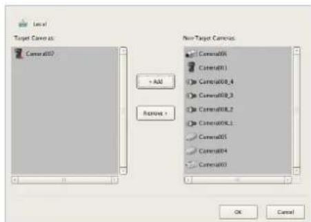
Camera List
Select the image size, frame rate, and other items for images captured from the camera, as necessary.
Adjust to Camera Settings
Match the values to those configured on the [Video] tab in "Device Configuration."
Note
When the time set for regular recording and alarm recording overlap, and the resolution for regular recording is set to 320 × 240 dpi and the resolution for alarm recording is set to 640 × 480 dpi, the resolution for images captured from the camera becomes 640 × 480 dpi. Normally, images captured from cameras use the maximum frame rate and resolution values for all actions during operation.
①OK
This creates a schedule in accordance with the set values, and closes the dialog box.
JCancel
This cancels your settings, and closes the dialog box.
Configuring Sensor Inputs
You can configure settings related to the sensor inputs incorporated in NSR and cameras, and Barionet (Barix I/O box) sensor inputs.
Sensor inputs can be specified and used for actions and schedule recording events.
Examples of sensor inputs:
Temperature, humidity, smoke, vibration, security, infrared, ultrasonic waves, etc.
You can configure the following settings for sensor inputs.
- "Changing Settings of Sensor Input Pins of NSR" (page 86)
- "Changing Settings of Sensor Input Pins of Camera" (page 86)
- "Changing Settings of Sensor Input Pins of Barionet" (page 87)
- "Adding Logical Sensor Input Pins to NSR" (page 87)
- "Deleting Logical Sensor Input Pins Created for NSR" (page 88)
Changing Settings of Sensor Input Pins of NSR
1 Click [Device] at the top of the Configuration window.
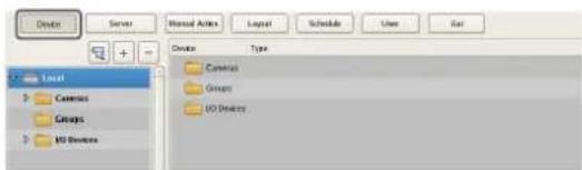
The Device Configuration screen appears.
2 Open [IO Device] in the [Device] tree, and click to select [System I/O].
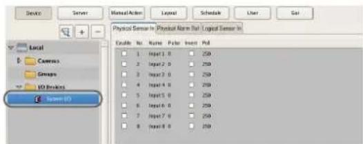
3 Configure each item on the [Physical Sensor In] tab, and click [Apply].
For details on each of the items, refer to "Setting Items of the [Logical Sensor In] Tab" (page 88).
The sensor input settings are changed.
Changing Settings of Sensor Input Pins of Camera
1 Click [Device] at the top of the Configuration window.
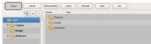
The Device Configuration screen appears.
2 Select the camera you want to change the settings of the sensor input pins from the [Device] tree.
3 Configure each item on the [Sensor In] tab, and click [Apply].
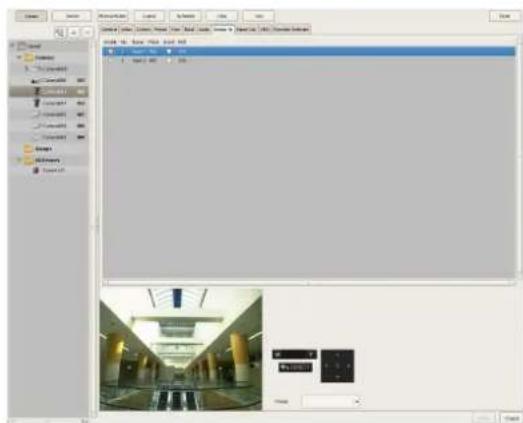
For details on each of the items, refer to "Setting Items of the [Logical Sensor In] Tab" (page 88).
The sensor input settings are changed.
Changing Settings of Sensor Input Pins of Barionet
Caution
- Barionet cannot be used via a proxy server.
- Manually perform device registration for Barionet before configuring the following settings.
- For details, refer to the operating manual for Barionet.
1 Click [Device] at the top of the Configuration window.
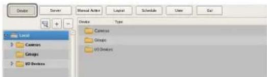
The Device Configuration screen appears.
2 Open [IO Device] in the [Device] tree, and click to select [Barionet].
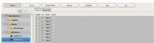
3 Configure each item on the [Sensor In] tab, and click [Apply].
For details on each of the items, refer to "Setting Items of the [Logical Sensor In] Tab" (page 88).
The Barionet sensor input settings are changed.
Adding Logical Sensor Input Pins to NSR
The adding of a logical sensor input pin to NSR allows for linking with the external device via the network. The operation (on/off) of the added sensor input pin from the external device acts as a trigger to perform recording or an action.
1 Click [Device] at the top of the Configuration window.
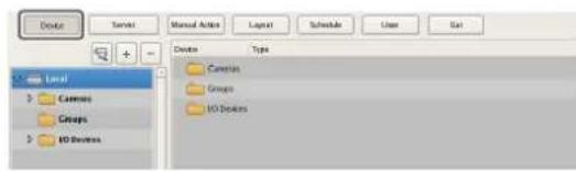
The Device Configuration screen appears.
2 Open [IO Device] in the [Device] tree, and click to select [System I/O].
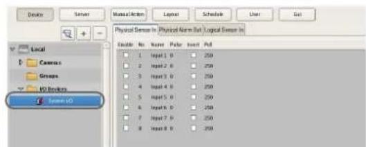
3 Add the logical sensor input pin on the [Logical Sensor In] tab.
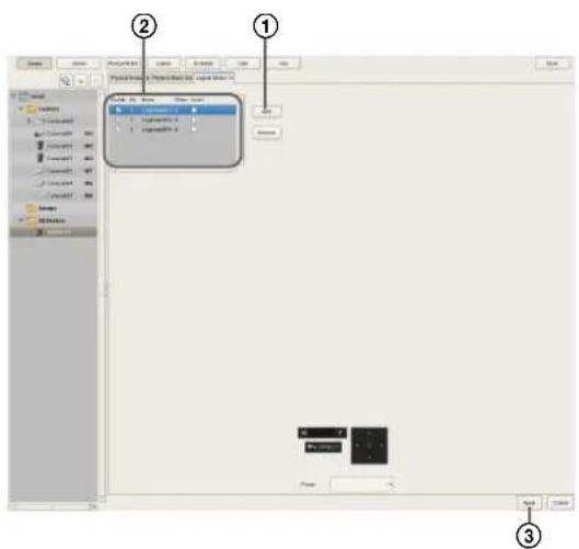
For details on each of the items, refer to "Setting Items of the [Logical Sensor In] Tab" (page 88).
①Click [Add]. The logical sensor input pin is added to the list.
②Configure each item.
③Click [Apply].
The logical sensor input pin is added.
Deleting Logical Sensor Input Pins Created for NSR
Note
The physical sensor input pins of NSR that exist by default cannot be deleted.
1 Open [IO Device] in the [Device] tree, and click to select [System I/O].
2 Select the check boxes for the logical sensor input pins you want to delete in the [Logical Sensor In] tab, and click [Delete].
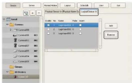
A confirmation message appears.
3 Click [Yes].
The logical sensor input pin is deleted.
Setting Items of the [Logical Sensor In] Tab
You can configure sensor input pins.
After configuring each item, click [Apply] to save your settings.
This example describes the screen for configuring physical sensor input pins of the NSR.
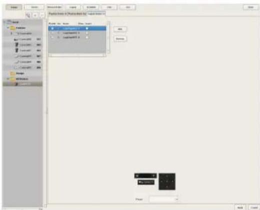
Sensor Input Pin List
This displays a list of the sensor input pins configured for the device selected in the tree structure.
Enable
Select the check boxes to enable the pins for the sensor inputs.
No
This displays the numbers of the sensor input pins. This item cannot be changed.
Name
Enter the names of the sensor inputs.
Pulse
Enter the duration in milliseconds to sustain pulse input once it is turned on.
Invert
Select the check box to invert the pulse polarity. Example: Invert High → Low to Low → High.
Add
This adds a logical sensor input pin to the list. This item is only displayed for the logical sensor inputs of “System IO.”
Delete
This deletes the selected sensor input pin from the list. This item is only displayed for the logical sensor inputs of "System IO."
Configuring Alarm Output Settings
You can configure settings related to the alarm outputs incorporated in NSR and cameras, and Barionet (Barix I/O box) alarm outputs.
Outputs are used to transmit alarms to devices equipped with alarm input functions, such as warning lights and door opening devices.
Example of Alarm Outputs:
Warning siren, warning light, light, door, etc.
You can configure the following settings for alarm outputs.
- "Changing Settings of Alarm Output Pins of NSR" (page 89)
- "Changing Settings of Alarm Output Pins of Camera" (page 89)
- "Changing Settings of Alarm Output Pins of Barionet" (page 90)
Changing Settings of Alarm Output Pins of NSR
1 Click [Device] at the top of the Configuration window.

The Device Configuration screen appears.
2 Open [IO Device] in the [Device] tree, and click to select [System I/O].
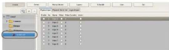
3 Configure each item on the [Alarm Out] tab, and click [Apply].
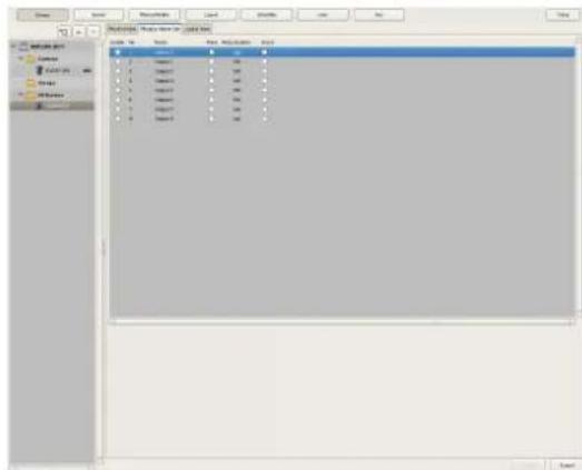
For details on each of the items, refer to “[Alarm Out] Tab (IO Device)” (page 90).
The alarm output settings are changed.
Changing Settings of Alarm Output Pins of Camera
1 Click [Device] at the top of the Configuration window.
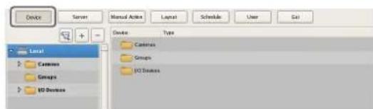
The Device Configuration screen appears.
2 Select the camera you want to change the settings of the alarm output pins from the [Device] tree.
3 Configure each item on the [Alarm Out] tab, and click [Apply].
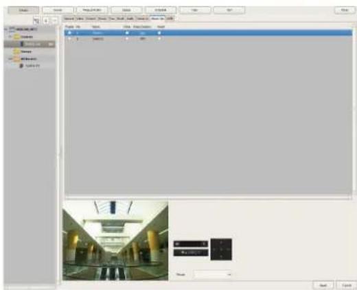
For details on each of the items, refer to “[Alarm Out] Tab (Camera)” (page 91).
The alarm output settings are changed.
Changing Settings of Alarm Output Pins of Barionet
Caution
- To use the alarm outputs of Barionet, it is necessary to connect to Barionet from a Web browser and enable the alarm output settings in advance.
- Barionet cannot be used via a proxy server.
- Manually perform device registration for Barionet before configuring the following settings.
- For details, refer to the operating manual for Barionet.
1 Click [Device] at the top of the Configuration window.
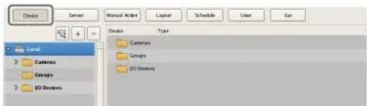
The Device Configuration screen appears.
2 Open [IO Device] in the [Device] tree, and click to select [Barionet].
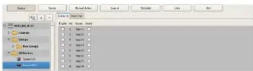
3 Configure each item on the [Alarm Out] tab, and click [Apply].
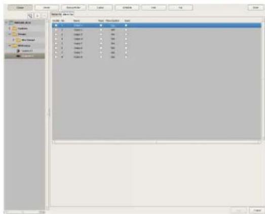
For details on each of the items, refer to “[Alarm Out] Tab (IO Device)” (page 90).
The Barionet alarm output settings are changed.
Setting Items of the [Alarm Out] Tab
[Alarm Out] Tab (IO Device)
You can configure the alarm output pins of NSR and Barionet.
After configuring each item, click [Apply] to save your settings.
This example describes the screen for configuring alarm outputs of NSR.
Alarm Output Pin List
This displays a list of alarm output pins configured for the NSR or Barionet selected in the tree.
Enable
Select the check boxes to enable the pins for the alarm outputs.
No
This displays the numbers of the alarm output pins. This item cannot be changed.
Name
Enter the names of the alarm outputs. They can be up to 32 characters long.
Pulse
Select the check box when you want to specify and enter a pulse interval. If you select this, enter the pulse interval in [Pulse Duration].
Pulse Duration
Enter the duration in milliseconds to sustain pulse output once it is turned on.
Invert
Select the check box to invert the polarity of the output pins.
Enabling invert does not change the state of the output pins. If you turn the output pins on/off when they are in an inverted state, the actual output signal state is inverted to off/on.
Also, in the case of output pins of the NSR unit, state initialization is performed according to the invert setting at startup.
(When inverted: On at startup, When not inverted: Off at startup)
[Alarm Out] Tab (Camera)
You can configure the alarm output pins of the camera selected in the tree.
After configuring each item, click [Apply] to save your settings.
Alarm Output Pin List
This displays a list of the alarm output pins configured for the camera selected in the tree.
Enable
Select the check boxes to enable the pins for the alarm outputs.
No
This displays the numbers of the alarm output pins.
This item cannot be changed.
Name
Enter the names of the alarm outputs. They can be up to 32 characters long.
Pulse
Select the check box when you want to specify and enter a pulse interval. If you select this, enter the pulse interval in [Pulse Duration].
Pulse Duration
Enter the duration in milliseconds to sustain pulse output once it is turned on.
Invert
Select the check box to invert the polarity of the output pins.
Enabling invert does not change the state of the output pins. If you turn the output pins on/off when they are in an inverted state, the actual output signal state is inverted to off/on.
Preview
This displays the images captured from the camera.
Configuring Action Settings
In NSR, you can configure the action for when, for example, a sensor input, VMD (recorder), VMF, or system alarm is detected, or for when a manual action is performed.
Relationship Between Events and Actions
When an event such as an alarm occurs...
The action corresponding to the event is performed.
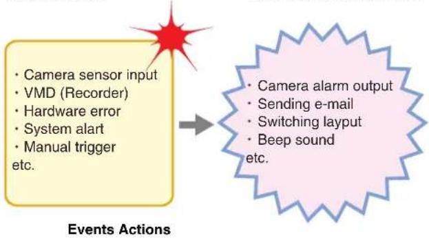
flowchart
graph LR
    A["Camera sensor input\nVMD (Recorder)\nHardware error\nSystem alert\nManual trigger etc."] --> B["Camera alarm output\nSending e-mail\nSwitching layout\nBeep sound etc."]
There are the following way of configuring actions.
• Manual Actions (page 92)
Configure an action for when a trigger occurs manually.
• Event/Alarm Actions (page 95)
Configure an action for when an alarm or event occurs during a specified schedule period.
Manual Action
Configure an action for when a trigger occurs manually.
Registering a Manual Action
1 Click [Manual Action] at the top of the Configuration window.
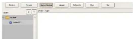
The Manual Action screen appears.
2 Click + (Add).
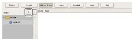
3 Configure the following items, and register the action.
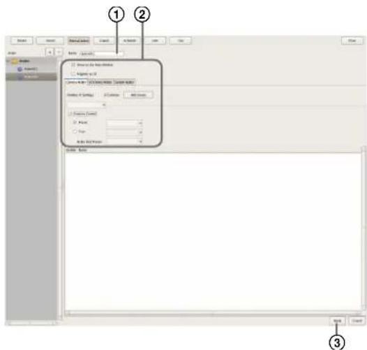
For details on each of the items, refer to "Setting Items of Manual Action Screen" (page 93).
①Enter a name for the action.
②Configure each item.
③Click [Apply].
The action is registered.
Performing a Manual Action
You can perform an action from the Manual Action toolbar in the main window.
1 Display the Manual Action pane in the main window.
Click in the pane at the top right of the screen, and select [Manual Action] from the menu that appears.
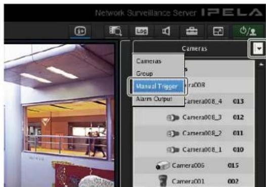
2 Select the action you want to perform, and click [Perform].
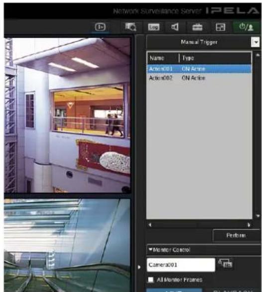
A confirmation message appears.
3 Click [OK].
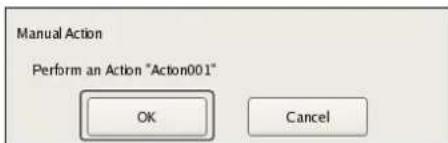
The action is performed.
Setting Items of Manual Action Screen
You can configure manual action settings.
The items that are displayed differ depending on the device for performing the action.
After configuring each item, click [Apply] to save your settings.
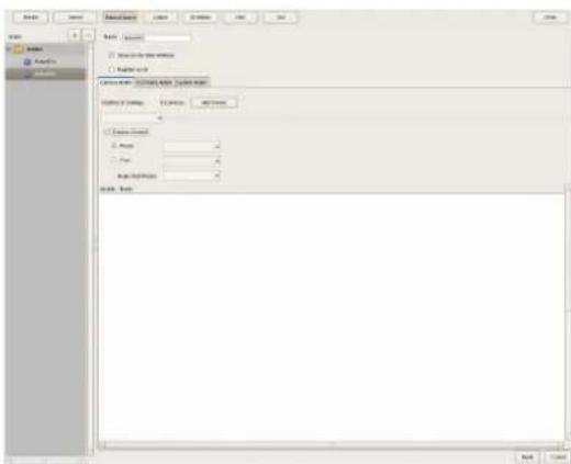
Name
Enter the name of the action. It can be up to 32 characters long.
Show on the Main Window
Select the check box to show this layout in the [Action] pane of the main window.
Register as OFF Action
Select the check box to register an action as an off action. Off actions operate as shown below.
Tour: Stops the tour
Alarm Output: Turns off alarm output
Beep: Stops the beep
[Camera Action] Tab
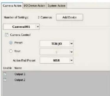
Number of Settings
This displays the number of cameras target for the action.
[Add Device] Button
This displays a dialog box for adding a camera as a target for the action.
Camera Drop-down Menu
Select a camera.
Camera Control
Select the check box to perform an action for controlling the camera, and specify the control method.
Preset
This returns the camera to the specified preset position.
Tour
This performs the specified camera tour.
Action End Preset
Specify the preset position for when the action ends.
Pin List
Select the check boxes for the pins to be target for performing an action to change the pin state.
[I/O Device Action] Tab
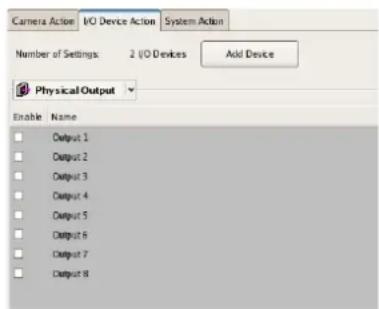
Number of Settings
This displays the number of IO devices target for the action.
[Add Device] Button
This displays a dialog box for adding an IO device as a target for the action.
IO Device Drop-down Menu
Select the I/O device.
Pin List
Select the check boxes of the pins for which to change the state.
[System Action] Tab
Screen example: For servers
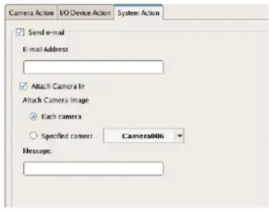
Send e-mail
Select the check box to send a notification by mail to a specified mail address.
E-mail Address
Enter an e-mail address.
Attach Camera Image
Select the check box to send a still image as a mail attachment.
If you select this, specify the camera for recording the still image.
Each camera
Attach the still images recorded with the camera for which the event occurred.
For example, when motion detection of camera A and sensor input of camera B are configured as the triggers and motion detection occurs for camera A, the still images recorded with camera A are attached. When the sensor input of camera B turns on, the still images recorded with camera B are attached.
Specified Camera
Record a still image with the specified camera.
Message
Enter the message of the mail. It can be up to 32 characters long.
Change Layout
Select the check box to change the monitor layout. If you select this, select the monitor layout to display on monitor 1.
This item is only displayed for a server.
Beep
Select the check box to play a beep tone.
If you select this, select a beep tone type.
This item is only displayed for a server.
Note
Pre-define an action for stopping the beep that is triggered by a manual or sensor input event.
Apply
This saves the settings.
Cancel
This cancels the changes to the settings.
Event/Alarm Actions
An action is performed if an alarm or event occurs within the duration set for a schedule. An action can be performed each time an alarm or event occurs, provided it occurs within the duration.
Caution
Even if the state changes as a result of an action being performing, the original state is not restored automatically.
Event/Alarm Action Example:
When an event/alarm action for moving the preset position to "Preset 2" if motion is detected by the VMD (camera) pin of camera 1:
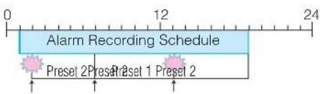
①When the VMD (camera) pin detects motion, the action is performed and the preset position of camera 1 moves to "Preset 2."
②The preset position is returned to "Preset 1" manually.
③When the VMD (camera) pin detects motion within the duration, the action is performed again and the preset position of camera 1 moves to "Preset 2."
Registering an Event/Alarm Action
Configure a schedule for performing an action when an alarm or event occurs within the duration set for the schedule. An action can be performed each time an alarm or event occurs, provided it occurs within the duration.
1 Click [Schedule] at the top of the Configuration window.

The Schedule Configuration screen appears.
2 Switch to recurrent view or date view.
3 Select [Action] in the tree, and select [New Action].
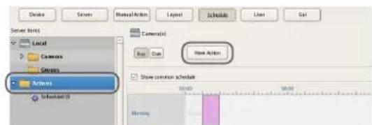
The New Action dialog box appears.
4 Configure each item, and click [OK].
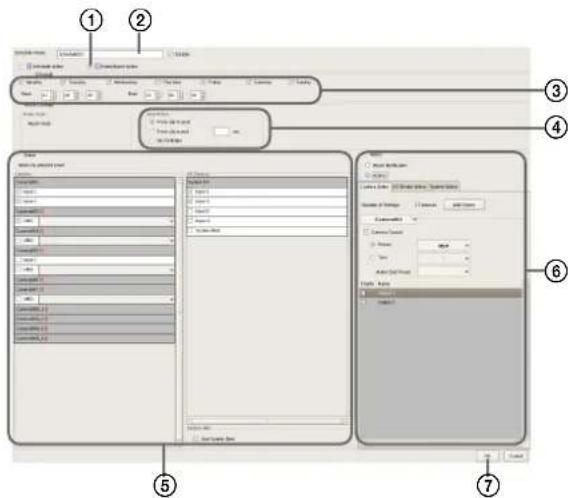
For details on each of the items, refer to "Setting Items of New Action Dialog Box (Event/Alarm Action)" (page 96).
①Select [Event/Alarm Action].
②Enter a name for the event/alarm action.
③Select the check boxes for the days you want to run the event/alarm action, and configure a start time and end time for the event/alarm action.
④Configure the timing for ending the action.
⑤Configure the event that will be the trigger for the action.
⑥Configure the action to perform.
⑦Click [OK].
The event/alarm action is created.
5 Click [Apply].
The event/alarm action is saved.
For details on how to view the schedule, refer to “Setting Items of Schedule Screen” (page 83).
Setting Items of New Action Dialog Box (Event/Alarm Action)
This dialog box is displayed by selecting [Action] from the tree in the Schedule Configuration screen, and then clicking [New Action].
After configuring each item, click [OK].
Screen example: When recurrent event/alarm action:
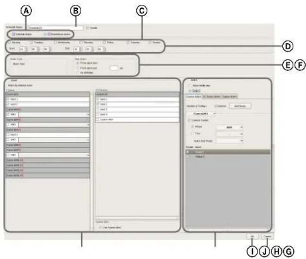
ⒶSchedule Action and Event/Alarm Action
Select the type of event/alarm action to configure. The setting items vary depending on this selection.
BName
Enter the name of the event/alarm action. It can be up to 32 characters long.
©Enable
Select the check box to enable this event/alarm action.
(D)Schedule
The settings differ depending on whether you are configuring a recurrent event/alarm action or an event/alarm action for a specific date and time.
When recurrent event/alarm action:
Select the check boxes for the days you want to run the event/alarm action, and configure a start time and end time for the event/alarm action.
The range that can be specified is 00:00:00 to 23:59:59 (hours/minutes/seconds).

When event/alarm action for a specific date and time:
Configure the start date and time and end date and time to apply the event/alarm action.

©Action Duration
Configure the duration for the action.
Action Start
This displays the timing for starting the action. This item cannot be changed.
Stop Action
Select the timing for ending the action.
From Event Start
This ends the action at the point in time a specified time elapses after the event started.
When this is selected, enter the period for after the event starts within the range of 1 to 3,600 seconds.
From Even End
This ends the action at the point in time a specified time elapses after the event ends.
When this is selected, enter the period for after the event ends within the range of 1 to 3,600 seconds.
No Definition
The timing to end the action is not specified.
FServer
Select the remote server.
This item is not displayed in the case of a client.
©Event
Configure the event that will be the trigger for the action.
Camera
Select the check box of the input pin to be the action trigger.
IO Device
Select the check box of the input pin to be the action trigger.
Note
The input configured for each camera and I/O device is displayed in the list. For the input pin settings, refer to "Configuring Motion Detection Settings" (page 59) and "Configuring Sensor Inputs" (page 86).
System Alert
Select the check box to use a system alert as the trigger.
©Action
Configure the action to perform.
Alarm Notification
Send an alarm notification for the configured trigger.
Action
This performs the specified action.
[Camera Action] Tab
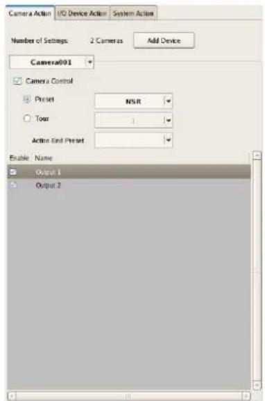
Number of Settings
This displays the number of cameras target for the action.
[Add Device] Button
This displays a dialog box for adding a camera as a target for the action.
Camera Drop-down Menu
Select a camera.
Camera Control
Select the check box to perform an action for controlling the camera, and specify the control method.
Preset
This returns the camera to the specified preset position.
Tour
This performs the specified camera tour.
Action End Preset
Specify the preset position for when the action ends.
Pin List
Select the check boxes for the pins to be target for performing an action to change the pin state.
[I/O Device Action] Tab
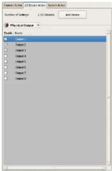
Number of Settings
This displays the number of IO devices target for the action.
[Add Device] Button
This displays a dialog box for adding an IO device as a target for the action.
IO Device Drop-down Menu
Select the I/O device.
Pin List
Select the check boxes of the pins for which to change the state.
[System Action] Tab
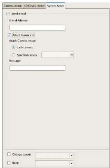
Send e-mail
Select the check box to send a notification by mail to a specified mail address.
E-mail Address
Enter an e-mail address.
Attach Camera Image
Select the check box to send a still image as a mail attachment.
If you select this, specify the camera for recording the still image.
Note
If the codec of the camera is MPEG4 or masking is set for the camera, the image is not attached.
Each camera
Attach the still images recorded with the camera for which the event occurred.
For example, when motion detection of camera A and sensor input of camera B are configured as the triggers and motion detection occurs for camera A, the still images recorded with camera A are attached. When the sensor input of camera B turns on, the still images recorded with camera B are attached.
Specified Camera
Record a still image with the specified camera.
Message
Enter the message of the mail. It can be up to 32 characters long.
Change Layout
Select the check box to change the monitor layout. If you select this, select the monitor layout to display on monitor 1.
Beep
Select the check box to play a beep tone. If you select this, select a beep tone.
①OK
This creates an event/alarm action in accordance with the set values, and closes the dialog box.
①Cancel
This cancels your settings, and closes the dialog box.
Configuring Mail Notification Settings
When an event occurs, a notification can be sent by e-mail to a pre-registered mail address.
You can configure a mail address for each action. Specify the SMTP server and sender address here.
1 Click [Server] at the top of the Configuration window.
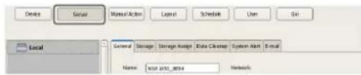
The Server Configuration screen appears.
2 Select the server for which you want to set the mail notification settings from the [Server] tree on the left of the screen.
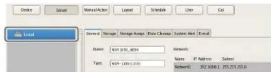
3 Configure each item on the [e-mail] tab, and click [Apply].
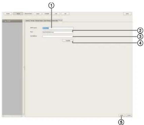
①Enter the address of the SMTP server.
②Enter the mail address of the sender.
③Enter the mail address for sending test mail.
④After you enter each address, click [Send Test Mail] and confirm that mail can be sent correctly.
⑤Click [Apply].
Configuring System Alert Settings
A system alert (alarm) can be generated when camera video loss or insufficient disk space is detected. Configure the settings for the action to perform after a system alert is generated.
1 Click [Server] at the top of the Configuration window.
The Server Configuration screen appears.
2 Select the server for which you want to set the system alert settings from the [Server] tree on the left of the screen.
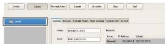
3 Configure the information to notify of in the system alert on the [System Alert] tab, and click [Apply].
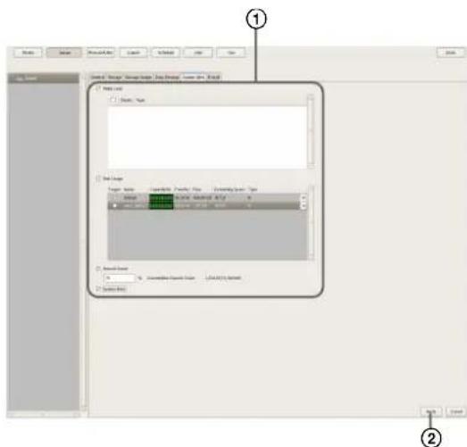
For details on each of the items, refer to "Setting Items of the [System Alert] Tab" (page 100).
①Select the check boxes for the notification items, and configure each item.
②Click [Apply]. The settings are saved.
4 Configure the action to perform after a system alert occurs.
For details on actions, refer to “Configuring Action Settings” (page 92).
Setting Items of the [System Alert] Tab
This tab is displayed by clicking [Server] in the [Configuration] window, and clicking the [System Alert] tab.
After configuring each item, click [Apply].
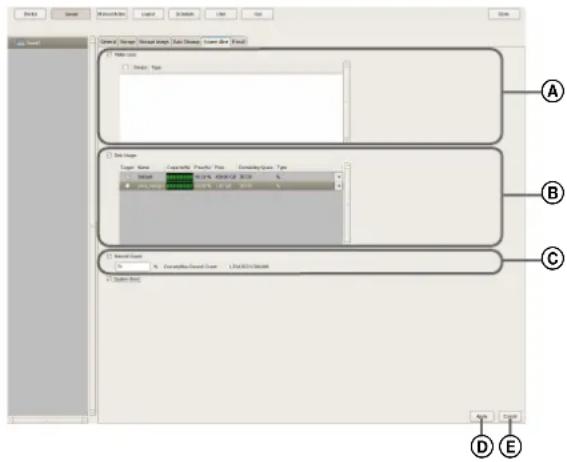
ⒶVIDEO LOSS
Select the check box to notify of the image signal becoming disconnected.
Note
Disconnection of the audio signal is not a target for detection.
Camera List
This displays a list of the video loss notification settings.
Target
Select the check boxes for the cameras to be target for notification.
Camera
This displays a list of the names of the cameras registered to NSR.
©Disk Usage
Select the check box to notify of insufficient remaining disk space.
Target Storage List
Select the check boxes for the storage to be target for notification.
Target
Select the check boxes for the storage to be target for notification.
Capacity
This displays the capacity of the storage.
This item cannot be changed.
Free (%)
This displays the amount of free space as a percentage.
Free
This displays the amount of free space in gigabytes.
Total
This displays the total size of the storage.
Remaining Space
Enter the remaining space limit at which to send notification as a percentage or in gigabytes.
©Record Count
Select the check box to notify of the record count exceeding a specified amount.
If you select this check box, enter the percentage of the maximum record count that the current record count needs to reach for notification to be sent.
Current/Max. Record Count
This displays the current record count and the maximum record count.
©Apply
This saves the settings.
©Cancel
This cancels the changes to the settings.
Caution
The hardware errors and recording errors of NSR are included in the system alerts, and notification always occurs regardless of the settings.
Registering Users
You can register users in NSR, and set login passwords and access permissions for each function. Five levels are provided for users ranging from the administrator level (Level 5) to the view level (Level 1). Permissions are granted as follows depending on the user level. You can also configure permissions individually for each user, as necessary.
Caution
- Be careful because if you forget the password for a user, the actions permitted only for that user will no longer be able to be performed.
- Only a user who has been granted the “User Configuration” permission can perform operations such as registering users and configuring user settings.
User Levels and Permissions
You can set the following five levels for users.
Level 1: Allowed to view monitoring and options windows.
Level 2: In addition to the permissions of Level 1, allowed to perform basic operations including camera control such as panning, tilting, and zooming, and searching for and playing back recording images.
Level 3: In addition to the permissions of Level 2, allowed to perform recording file operations such as managing logs, deleting and protecting files, and exporting.
Level 4: In addition to the permissions of Level 3, allowed to configure device settings such as registering devices and creating layouts and schedules.
Level 5: In addition to the permissions of Level 4, allowed to perform all operations including configuring settings and configuring menus as an administrator.
| Permission User Level | |||||
| 1 2 3 4 5 | |||||
| User Configuration None | None | None | None Yes | ||
| Administrator Menu Setting | None | None | None None Yes | ||
| Schedule Configuration | None | None | None Yes Yes | ||
| Device Configuration None | None | None | Yes Yes | ||
| Server Configuration None | None | None | Yes Yes | ||
| Layout Configuration None | None | None | Yes Yes | ||
| GUI Configuration None | None | None | Yes Yes | ||
| Manual Action Configuration | None | None | None Yes Yes | ||
| Permission User Level | |||||
| 1 2 3 4 5 | |||||
| Manual Deletion/Protection | None | None Yes Yes Yes | |||
| Log Control | None | None Yes Yes Yes | |||
| Export Control | None | None Yes Yes Yes | |||
| Exit Server | None | None Yes Yes Yes | |||
| Search & Playback | None | Yes | Yes | Yes | Yes |
| Camera Control | None | Yes Yes Yes Yes | |||
| Output Control | None | Yes Yes Yes Yes | |||
| Layout Control | None | Yes | Yes | Yes | Yes |
| Manual Record | None | Yes Yes Yes Yes | |||
| Manual Action | None | Yes Yes Yes Yes | |||
| Capture Control | None | Yes Yes Yes Yes | |||
| Display Control | None | Yes | Yes | Yes | Yes |
| Alarm History Control | None | Yes | Yes | Yes | Yes |
| Exit Application | Yes | Yes | Yes | Yes | Yes |
Registering a User
Register the user to use NSR, and configure the permissions.
1 Click [User] at the top of the Configuration window.
The User Configuration screen appears.
2 Select a level for the user you want to register in the [User] tree, and click (Add).
The user is added to the tree.

3 Configure each item, and click [Apply].
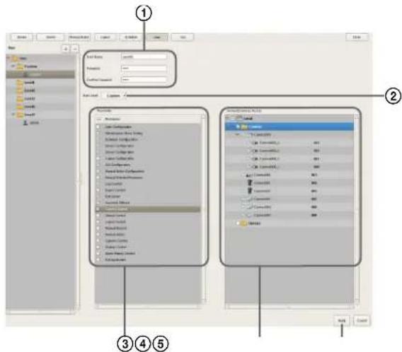
For details on each of the items, refer to "Setting Items of the [User] Tab" (page 103).
①Enter the user name and password. They can be up to 32 characters long and consist of single-byte alphanumeric characters, hyphens (-), and underbars (_).
②Change the user level, as necessary.
Select “Custom” when you want to set the permissions individually.
③Select the check boxes for the permissions to grant to the user.
④To configure access permissions for each device, select the check boxes of the devices to which to grant access permissions.
⑤Click [Apply].
The settings are saved.
Note
If "Custom" is selected for the user level, the [Custom] tree is displayed.
Changing User Settings
1 Select the user you want to change the settings of from the [User] tree on the User Configuration screen.
2 Reconfigure the items you want to change.
For details on each of the items, refer to "Setting Items of the [User] Tab" (page 103).
3 After configuring each item, click [Apply].
The settings are changed.
Deleting a User
1 Select the user you want to delete from the [User] tree on the User Configuration screen.
2 Click - (Delete).
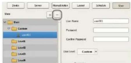
A confirmation message appears.
3 Click [OK].
The user is deleted.
Setting Items of the [User] Tab
This tab allows you to register users and configure permissions.
It is displayed by clicking [User] in the Configuration window.
After configuring each item, click [Apply] to save your settings.
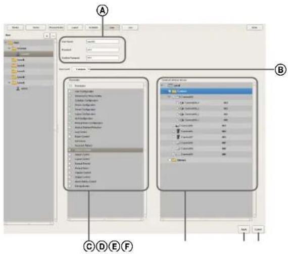
ⒶUser
Enter the user name. It can be up to 32 characters long and consist of single-byte alphanumeric characters, hyphens (-), and underbars (_).
Password
Enter the password. It can be up to 32 characters long and consist of single-byte alphanumeric characters, hyphens (-), and underbars (_).
Confirm Password
Enter the same password again for confirmation.
®User Level
Select a user level.
Select "Custom" when you want to set the permissions individually.
©Permission
Select the check boxes for the permissions to grant to the user.
The following is an example of the types of permissions that are available.
Camera Control
This allows camera control on the Camera Control pane.
Search & Playback
This allows searching for and playing back recording data.
Export Control
This allows exporting recording images.
User Configuration
This allows configuring and changing user accounts on the User Configuration screen.
Device Configuration
This allows adding and deleting devices on the Device Configuration screen.
©Servers/Cameras Access
Select the check boxes for the devices or servers to grant access permissions to the user.
©Apply
This saves the settings.
⑤Cancel
This cancels the changes to the settings.
Caution
If there is no permission to access a server, logging on to that server is not possible.

Configuring the Duration to Rewind for Quick Playback
When you click [PLAYBACK] in the Main screen, the selected monitor frame enters the playback state, and playback automatically starts after rewinding a specified duration. (This function is referred to as “quick playback.”)
You can configure the duration to rewind for quick playback in the GUI Configuration screen.
1 Click [GUI Configuration] at the top of the Configuration screen.
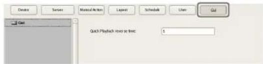
The GUI Configuration screen appears.
2 Enter the duration to rewind for quick playback in seconds, and click [Apply].
The duration to rewind for quick playback is configured.
Note
You can set a time of 10 seconds or longer.
Operation and Control
Chapter
5
Monitoring
You can monitor the live images currently being captured by the camera, as well as the audio from the camera. You can also perform monitoring using the layout tour function for sequentially switching the display shown on the display at a preset time.
This section describes the following monitoring operations.
• "Monitoring Live Images" (page 105)
- "Monitoring Using Layout Tours" (page 106)
• "Monitoring Audio from Cameras" (page 106)
Note
To use the layout tour function, a layout tour needs to be configured in advance. For the configuration procedure, refer to "Configuring Layout Tours" (page 58).
Monitoring Live Images
You can monitor the images the camera is currently capturing in any monitor frame.
1 Click the monitor frame to display the live images on the main screen.
2 Click [LIVE] on the Monitor Control pane.
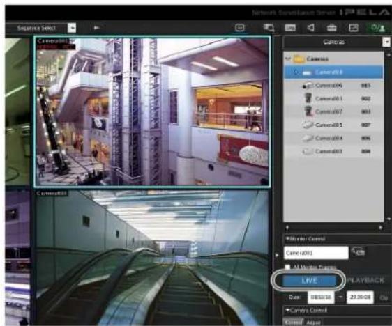
Live images are displayed on the selected monitor frame.
For details on each of the items, refer to "Functions and Operating Procedure of Main Screen" (page 107).
Monitoring Images of a Different Camera
Select a camera on the Camera pane, and drag and drop it onto the monitor frame to switch to displaying the images of the selected camera.
You can also switch to the images of a selected camera by clicking to select a monitor frame, and then double-clicking a camera in the Camera pane.
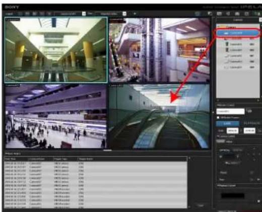
Note
When the Camera pane is not displayed, click and select [Camera] from the menu that appears to switch to the Camera pane.
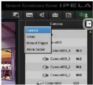
Changing the Layout
Select a layout on the [Layout] toolbar at the top of the main screen to change the layout.
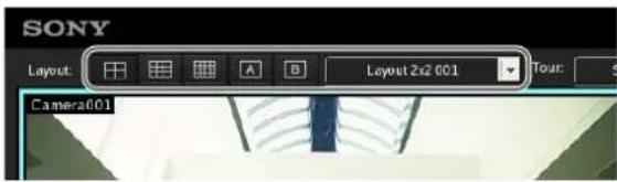
Monitoring Using Layout Tours
You can perform monitoring using the layout tour function for sequentially switching the display shown on the display at a preset time.
Note
To use the layout tour function, a layout tour needs to be configured in advance. For the configuration procedure, refer to "Configuring Layout Tours" (page 58).
1 Select a layout tour on the [Tour] toolbar at the top of the main screen.
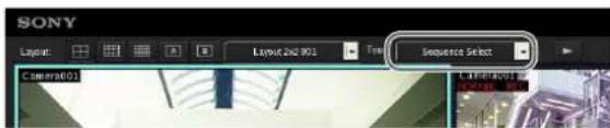
2 Click (Layout Tour Start).
The sequence operation starts.
If you click again, the layout tour ends.
Monitoring Audio from Cameras
If you are using a camera with support for audio input, you can monitor the audio input from the camera.
Select the monitor frame for which you want to monitor the audio to output audio from the camera assigned to the selected monitor frame.
If multiple monitor frames are selected, audio is only output from the camera of the one selected last.
Adjusting the Volume
1 Click (Adjust Volume).
The Volume Control dialog box appears.
2 Adjust the volume with the slider, and click [OK].
When you want to disable the sound, select the [Mute] check box.
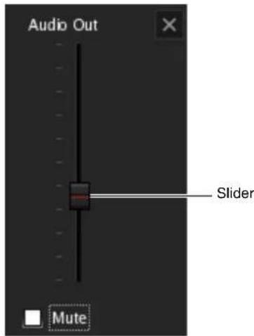
Note
In the disable state, audio is no longer output no matter which monitor frame you select.
Functions and Operating Procedure of Main Screen
On the main screen, you can perform operations such as monitoring the live images captured from the current camera and playing back recorded images.
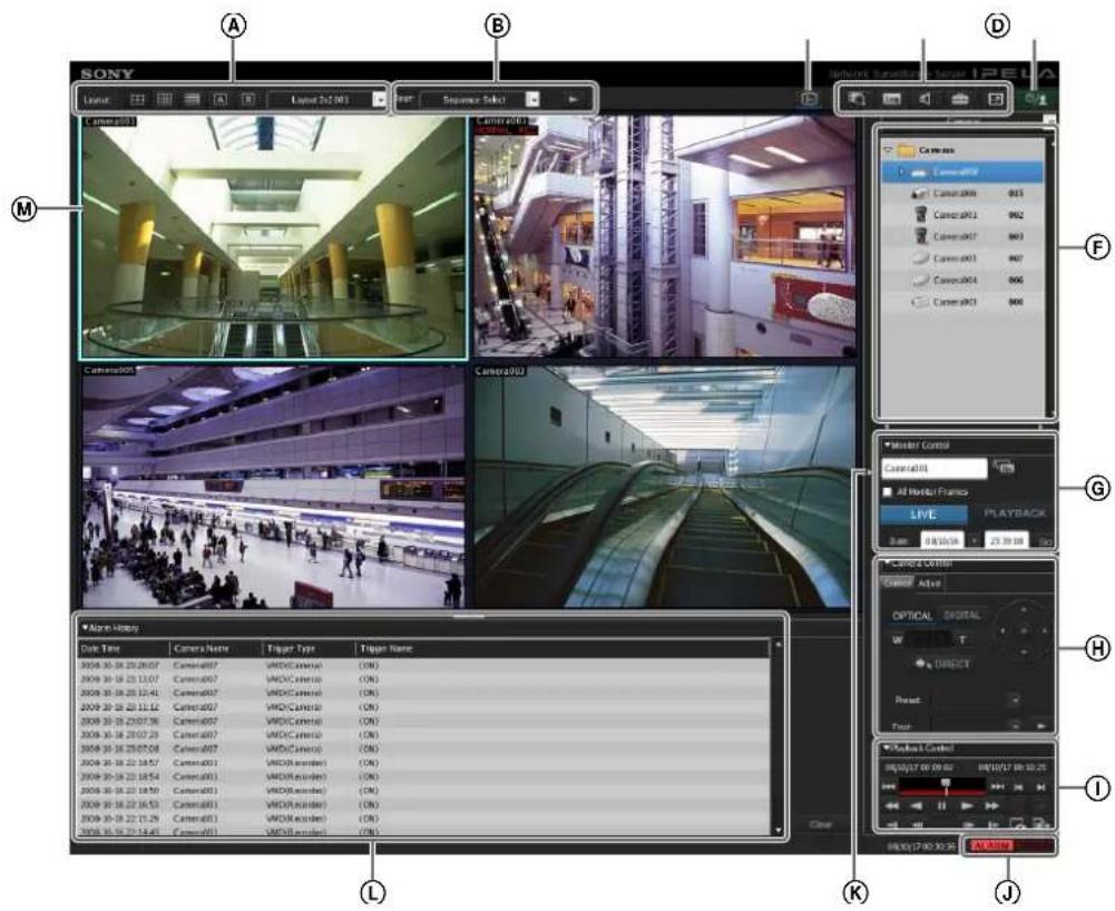
Ⓐ[Layout] Toolbar
Use this to change the layout.
![SONY NSR1100 - Ⓐ[Layout] Toolbar - 1](/content/2026/05/859819/images/cabf1ce5f1560b610a1aaef87457a5727e32144e04748cae2338517ae1248d43.jpg)
(2×2 Layout)
This switches to the 2×2 default layout.

(3×3 Layout)
This switches to the 3×3 default layout.

(4×4 Layout)
This switches to the 4×4 default layout.

(Custom A Layout)
This switches to the layout of the Custom A group.

(Custom B Layout)
This switches to the layout of the Custom B group.
Layout Menu
Select a layout from the drop-down menu.
⑧[Tour] Toolbar
This is used when executing a layout tour.
Tour Menu
Select a layout tour from the drop-down menu.

(Layout Tour Start/Stop)
This starts or stops the layout tour.
© (Display Information)
This displays or hides the information of the monitor frame configured in the layout settings.
(D) (Search Recording Data)
This displays the Search window (page 119) for specifying search conditions.
Log (Open Log Window)
This displays the [Log] window (page 128) for displaying the recent log messages.
(Volume Control)
Adjust the volume for audio output from NSR. The audio of the camera of the selected monitor frame is output.
(Configuration)
This displays the Configuration window (page 39) for configuring settings such as device registration and camera operation.
(Full Screen)
This displays the current layout (monitor arrangement) over the whole screen.
Switching to full screen hides the control buttons and other items.
(Cancel Full Screen)
This returns from the full screen display to the normal screen.
This button is displayed in full screen display when you align the cursor with the top-right corner of the screen.
You can also return to the normal screen by pressing the Esc key on the keyboard.


This allows you to log off, activate the lock, reboot, or shutdown.
⑤Camera/Group/Manual Action Pane
Clicking displays a menu that allows you to switch to each of the panes.
Camera Pane
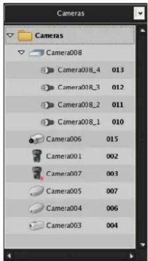
This allows you select the camera for displaying images in the monitor frame.
Select a camera from the tree, and drag and drop it onto the monitor frame to switch to displaying the images of the selected camera.
Groups Pane
This displays a camera list for each device group, and you can select the camera for which to display images in the monitor frame.
Select a camera from the tree, and drag and drop it onto the monitor frame to switch to displaying the images of the selected camera.
Manual Action Pane
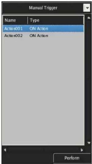
This allows you to perform an action manually. Select an action from the list, and click [Perform].
©Monitor Control Pane
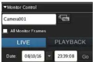
This allows you to switch between live images and recorded images.

This displays the name of the camera assigned to the selected monitor frame. To change the camera assignment, click 📄 camera ID Select), enter the ID of the camera in the input box and press the Enter key.
All Monitor Frames
If you select this check box, all monitor frames become applicable during live/playback switching and quick playback.

Click [LIVE] to monitor live images in the selected monitor frame, and [PLAYBACK] to play back recorded images.
Also, when you select a monitor frame, the button lights to indicate whether the state is live or playback. If you click [PLAYBACK], the selected monitor frame enters the playback state, returns to the time set in "GUI Configuration," and then starts playback automatically. (This function is called "quick playback.")

This allows you to specify a date and time for the playback position of the recorded images. Specify a date and time, and click [Go] to play back the recorded images from the specified position in the selected monitor frame.
©Camera Control Pane [Control] Tab
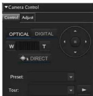
This allows you to control the images from the camera.
OPTICAL
This switches the camera to optical zoom mode.
DIGITAL
This displays the images enlarged or reduced on the monitor.
Wide-angle/Telephoto Zoom
This zooms images in the wide-angle and telephoto directions.
[W] is the wide-angle end (zoom out), and [T] is the telephoto end (zoom in).
Click between "W" and "T" to zoom to an absolute value.
If you click this button, you can perform pan, tilt, zoom, and centering with the mouse.
You can also use the following shortcut keys.
| Shortcut keys Operations | |
| Ctrl + Left-click Moves the | camera so thatthe selected point becomesat the center. |
| Ctrl + Left-click and drag | Displays a red box, andreleasing the mouse buttonenlarges the portion of theimage inside the box to fillthe window. |
| Ctrl + Rotate the wheelforward1) | Zooms in. |
| Ctrl + Rotate the wheelbackward1) | Zooms out. |
1) Zooming in and zooming out in digital are not supported.
Pan/Tilt
natural_image
Circular control knob with directional arrows, no text or symbols visibleThis moves the camera up, down, left, or right.
Preset
This moves the camera to the selected preset position.
Tour
This performs the selected camera tour.
[Adjust] Tab
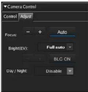
This allows you to adjust the images from the camera.
Focus

Select [AUTO] to always adjust the focus automatically.
You can click [-] or [+] to cancel the auto state, and adjust the focus manually. Adjust the focus in the [+] direction to focus on a subject that is close and adjust the focus in the [-] direction to focus on a subject that is far away. When you perform the pan, tilt, and zoom operations of the camera, [AUTO] is set automatically.
Brightness (EV)
Select [AUTO] to always adjust the brightness automatically.
You can click [-] or [+] to cancel the auto state, and adjust the brightness manually. Adjust the brightness in the [+] direction to make the images brighter and adjust the brightness in the [-] direction to make the images darker.
The backlight compensation turns on or off each time you click [BLC ON].
When you perform the pan, tilt, and zoom operations of the camera, [AUTO] is set automatically.
Day/Night

Select on (night mode) or off (day mode) when the camera has a day/night function.
①Playback Control Pane
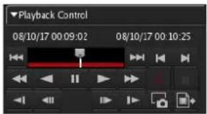
This is used when playing back recordings.
You can also export a recorded image as a file, and export one scene of the recorded images as a still image file.
Date and Time Indication

This displays the date and time that an image was recorded.

Click 📂 Previous Alarm) to jump to the previous alarm in the recording data, and click 📂 Next Alarm) to jump to the next alarm.
By dragging the slider, you can move the playback position to any point.
(Rewind)
This rewinds images.
Also, each click of the button changes the rewind speed as follows:

(Reverse Play)
Plays back images in reverse (at 1x speed).
II (Pause)
This pauses playback.
(Play)
Plays back images (at 1x speed).
When metadata is recorded and a Video Motion Filter is configured, images play back simultaneously (at 1x speed only).
(Fast Forward)
This fast-forwards images.
Also, each click of the button changes the fast forward speed as follows:

(Slow Rewind)
This plays back images in reverse at slow speed (at 1/5x speed).
(Previous Frame)
This rewinds one frame.
(Next Frame)
This advances one frame.
(Slow Forward)
This plays back images at slow speed (at 1/5x speed).
(Previous Recording)
This jumps to the previous recording.
(Next Recording)
This jumps to the next recording.
(Start Recording)
This starts recording images from the camera selected for the camera monitor frame.
(Stop Recording)
This stops recording.
(Capture Still Image)
This exports one scene of recorded images as a still image file.
Still images are exported in JPEG format. For details, refer to “Exporting Recorded Images as Still Images” (page 126).
(Export Recorded Image)
This exports a recorded image as a movie file. Video is exported in a native format (.cam file). Exported video can be played back with an application for playing CAM files.
①[ALARM] Lamp
![SONY NSR1100 - ①[ALARM] Lamp - 1](/content/2026/05/859819/images/ae5008d9c6e1fd172cfb084302ad560e84e07b13c63772927e7b1089d97d6959.jpg)
This is lit when an alarm has occurred.
[ERROR] Lamp
![SONY NSR1100 - [ERROR] Lamp - 1](/content/2026/05/859819/images/3ab3d25efdf43748dc71e2154bca910a3b9d969596019564f1a2eab7bc60262f.jpg)
This is lit when an error has occurred.
©Expand/Collapse Pane Button
This displays or hides the pane section.
①Alarm History Pane
This displays the history of when alarms occurred. Click the beginning of the title to display or hide the list.
You can also change the size of the pane by dragging the top of the pane with the mouse.
Clear
This clears the history.
©Monitor Frames
You can display live images and play back recorded images in each of the monitor frames.
To monitor live images, click a monitor frame and then click [LIVE].
To play back recorded images, click a monitor frame and then click [PLAYBACK].
When a Click Action is Configured
When an action is set for an image pasted in the layout or a monitor frame, the pointer changes if the mouse is held over the position of the specified object.
If you click the mouse at the place where the pointer changed, the action is executed.
Second Monitor (Monitor 2)
If two monitors are connect to this unit, the 1 × 1 , 2 × 2 , 3 × 2 , or 3 × 3 monitor layout that was specified is displayed on the monitor connected to monitor connector 2. You can also use monitor 2 as the hotspot monitor.
Screen of Monitor 1 Screen of Monitor 2
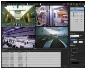
natural_image
Four-panel collage showing interior views of a modern building with curved architecture and large windows (no visible text or symbols)The displayed images are the same as those of the monitor frame selected in monitor 1. However, if sensor input or motion detection occurred, the images of the corresponding camera are displayed.
The operation when two monitors are connected is as described below.
- The selected image or the image of the camera with which there was a sensor input or motion detection is displayed on an available monitor frame in order from top left, top right, bottom left, and bottom right.
- If the same image is already displayed in a monitor frame, it is not displayed in another monitor frame.
Notes
- The setting operation is not possible for monitor 2.
- Displaying images on monitor 2 may reduce the display performance of monitor 1.
Monitor Frame
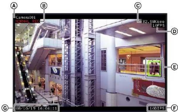
ⒶCamera Name
This displays the name of the camera.
BState
This displays the recording type (MANUAL REC, ALARM REC, or SCHEDULE) during recording. During the playback of recorded images, the playback operation state (PAUSE, etc.) or playback speed (+1x, -0.2x, etc.) is displayed (“+” is used to indicate playback speed in the forward direction, and “-” to indicate playback in the reverse direction).
©Bandwidth
This displays the amount of bandwidth used for transferring images over a network connection.
(D)Frame Rate
This displays the speed at which images are imported from the camera.
©VMD (Recorder):
This displays the detection criteria for Video Motion Detection (Recorder).
⑤Display Images per Second
This display the speed at which the camera images are refreshed on the monitor.
©Time
This displays the current date and time during the monitoring and recording of live images, and the date and time at the time of recording when playing back recorded images.
Notes
- In the monitor frame is set as the hotspot, the images of the corresponding camera are displayed in cases such as the following.
- When the monitor frame is selected.
- When there was a sensor input.
- When a motion detection or VMF package alarm occurred.
- When a sensor input, motion detection, or VMF package alarm has occurred and the images of the corresponding camera are displayed on the monitor frame, a red frame is displayed.
Switching a Monitor Frame to 1x1 View
Double-click on a monitor frame to switch the layout of that monitor frame to 1×1 view.
Double-click the monitor frame again to restore the original layout.
Note
If you switch to another layout or the layout is switched by an action or layout tour after switching to 1×1 view, double-clicking will not restore the original layout.
Controlling Cameras
When monitoring with a camera equipped with pan and tilt functions, you can monitor images from the camera while performing pan, tilt, and zoom operations on the Camera Control pane on the right side of the screen or with the mouse.
For details on the operating procedure of the Camera Control pane, refer to "Functions and Operating Procedure of Main Screen" (page 107).
Note
Camera control is only enabled for network compatible cameras.
Performing Pan, Tilt, and Zoom Operations
Using Camera Control Pane to Control Camera
1 Select any monitor frame, and display the images of the camera you want to control.
2 Use the Camera Control pane to control the camera.
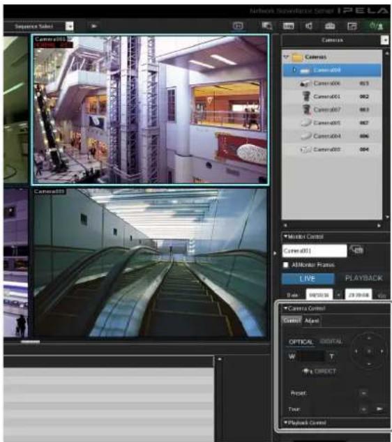
Using Mouse to Control Camera
By operating the mouse over the image displayed in a camera monitoring window, you can perform camera operations such as centering, panning, tilting, and zooming.
1 Select any monitor frame, and display the images of the camera you want to control.
2 Click on the Camera Control pane.
■Centering the Image
If you click the mouse on the image, the camera centers on the location that was clicked.
natural_image
Interior view of a modern, empty multi-level building with golden pillars and glass railings (no visible text or symbols)■Performing Pan, Tilt, and Zoom Operations
If you click and drag the mouse over the image, a red box appears.
When the mouse button is released, the camera moves until the portion of the image inside the red box fills the window.
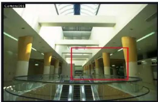
natural_image
Interior view of a modern multi-level hotel lobby with golden pillars and a glass railing (no visible text or signage)■Performing Zooming In and Out Operations
When using a mouse with a scroll wheel, you can zoom in and out by rotating the wheel.
- Rotate the wheel forward to zoom in.
- Rotate the wheel backward to zoom out.
Using Camera Presets
You can move the camera to preset positions stored on the camera.
Note
You can also configure a new preset. For the configuration procedure, refer to "Configuring Preset Positions" (page 44).
1 Select any monitor frame, and display the images of the camera you want to control.
2 Select a preset in [Preset] on the Camera Control pane.
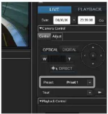
The camera moves to the preset position.
Performing Camera Tours
You can perform “tours,” in which the camera moves successively to preset pan, tilt, and zoom positions. The camera only stops at each preset position for the duration set in advance.
Note
To use the camera tour function, a camera tour needs to be configured in advance. For the configuration procedure, refer to "Configuring Camera Tours" (page 45).
1 Select any monitor frame, and display the images of the camera you want to control.
2 Select a camera tour in [Tour] on the Camera Control pane, and click Start Camera Tour).
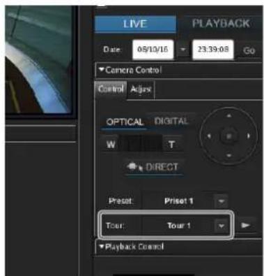
The camera tour is performed.
Recording, Searching, and Playing Images
You can record live images, and search and play back recorded image data and audio data.
This section describes the following operations.
- "Recording Live Images" (page 116) You can record the images currently being captured by a camera.
- "Playing Recorded Images" (page 116) Simple operations are available for playing recorded images, including quick playback for automatically rewinding a specified amount of time and playing, specifying a date and time and playing, and playing from alarm history.
- "Searching Recorded Images" (page 117) You specify a date and time or type of recording to search for recorded images.
- "Playing Recorded Images from Search Results" (page 118)
You can play recorded images from Search Results.
Recording Live Images
You can record the images currently being captured by a camera.
1 Select the monitor frame for which you want to record live images.
Note
If no live images are displayed, click [LIVE] on the Monitor Control pane.
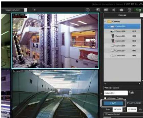
2 Click (Start Recording) on the Playback Control pane.
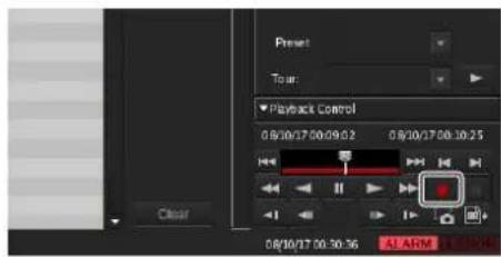
Recording starts.
Note
Recording continues even if you change the layout.
3 Click (Stop recording) to stop recording.
A confirmation message appears.
4 Click [Yes].
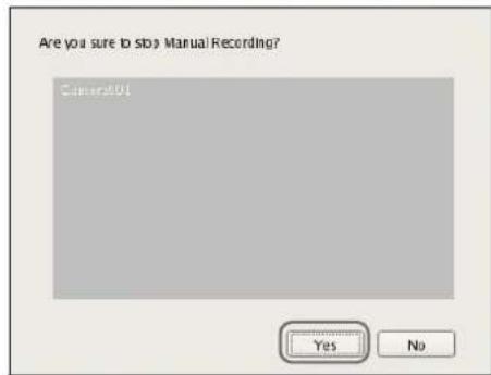
Recording stops.
Playing Recorded Images
Simple operations are available for playing recorded images, including quick playback for automatically rewinding a specified amount of time and playing, specifying the playback position by date and time, and playing from alarm history.
Quick Playback
Clicking to select a monitor frame and then clicking [PLAYBACK] rewinds the recorded images by a preset amount of time, and plays them automatically.
Note
You can configure the rewind time for quick playback on the GUI Configuration screen (page 104).
Specifying a Date and Time and Playing
This allows you to specify a date and time for the playback position of the recorded images.
1 Click to select the monitor frame to which the camera of the recorded images you want to play is assigned.
2 Specify a date and time in [Date] in the Monitor Control pane, and then click [GO].
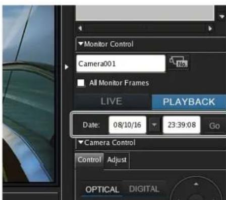
The recorded images are played back from the specified position.
Playing from Alarm History
1 Click to select the monitor frame of the recorded images you want to play.
2 Click the alarm history in the Alarm History pane.
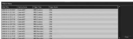
The recorded images are played back.
Searching Recorded Images
There are the following types of search.
- Normal Search
You can specify the recording type (schedule recording, manual recording, alarm recording, or event recording) and then search.
- Object Search
You can search for previously recorded images using the VMD (recorder) motion detection function and VMF function.
Normal Search
You can specify the recording type (schedule recording, manual recording, alarm recording, or event recording) and then search.
1 Click Search for Recording Data) at the top of the main screen.
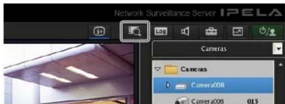
The Search Window appears.
2 Specify the search conditions, and click [Search].
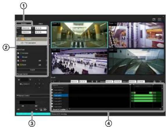
For details on each of the items, refer to “Setting Items of Search Window (Normal)” (page 119).
①Click [Normal].
②Specify the search conditions.
③Click [Search].
A list of search results is displayed (④). You can play recorded images from the search results. For details, refer to “Playing Recorded Images from Search Results” (page 118).
Object Search
You can search for previously recorded images using the VMD (recorder) motion detection function and VMF function.
1 Specify the search conditions and click [Search] in the Search Window.
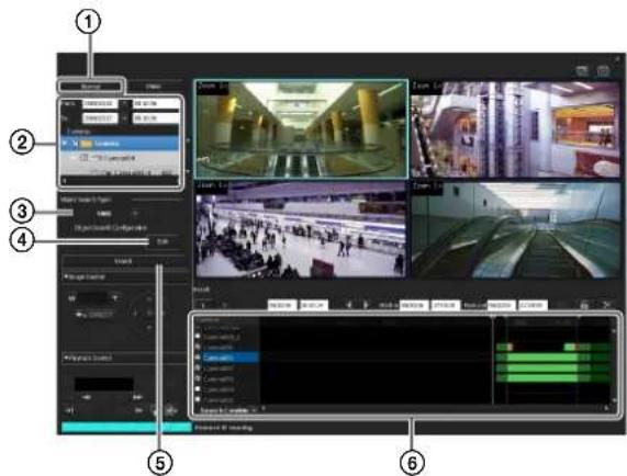
For details on each of the items, refer to "Setting Items of Search Window (Object)" (page 119).
①Click [Object].
②Specify the search conditions.
③Select [VMF] or [VMD (Recorder)].
④Click [Edit], configure each of the items in the dialog box that appears, and click [OK].
When VMD (Recorder)
Configure the detection areas.
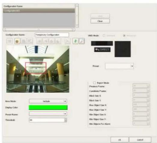
For details on each of the items, refer to "Setting Items of Object Search Configuration Dialog Box (VMD)" (page 120).
When VMF
Specify the VMF package to use.
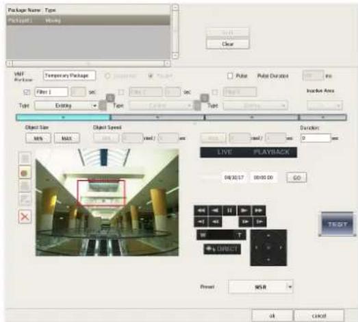
For details on each of the items, refer to "Setting Items of Object Search Configuration Dialog Box (VMF)" (page 120).
⑤Click [Search].
A list of search results is displayed (6).
Playing Recorded Images from Search Results
You can play recorded images from the search results.
1 Search for the recorded images in the Search Window.
2 Select the monitor frame for playing the recorded images.
3 Play the recorded images.
Screen example: List view
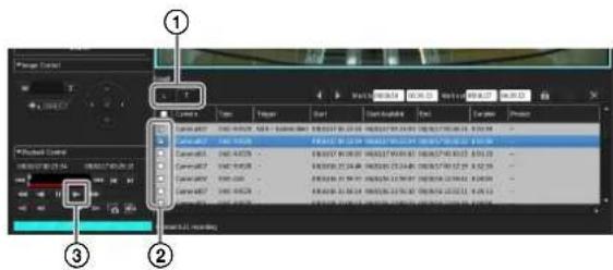
For details on each of the items, refer to “Search Results Display Area (List View)” (page 121) and “Search Results Display Area (Timeline View)” (page 121).
①Switch to the timeline view or list view, as necessary. Clicking 📄 Mode) switches to the list view and clicking 📄 timeline Mode) switches to the timeline view.
②Select the check box of the recorded images you want to play.
③Click ▶ (Play).
The recorded images are played in the selected monitor frame.
You can perform operations such as enlarging, reducing, fast forwarding, and rewinding images on the Image Control pane and Playback Control pane.
Details of Search Window
Setting Items of Search Window (Normal)
Specify the search conditions for a normal search. Configure each of the items and click [Search] to perform a search with the specified search conditions.
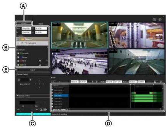
Ⓐ[Normal] Tab
Select this to specify the recording type (schedule recording, manual recording, alarm recording, or event recording) and then search.
⑧Date and Time Specification Area
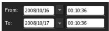
Specify a range of dates and times for which to search.
©Device Specification Area
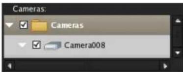
Specify the devices for which to search.
Select the check boxes of the devices for which to search in the tree.
(D)Recording Type
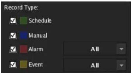
Select the check boxes of the recording types for which to search.
When you select the check boxes of [Alarm] and [Event], select the recording triggers from the drop-down menus.
ESearch Button
This performs a search with the specified conditions.
Setting Items of Search Window (Object)
Specify the search conditions for an object search. Configure each of the items and click [Search] to perform a search with the specified search conditions.
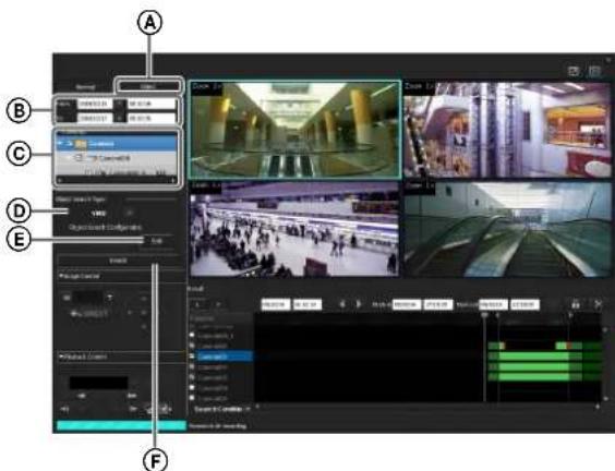
Ⓐ[Object] Tab
Select this to search with motion detection of VMD (recorder) as the trigger, or apply filters (VMF: Video Motion Filter) consisting of motion/object search conditions to search for the corresponding recordings.
⑧Date and Time Specification Area
Specify a range of dates and times for which to search.
©Device Specification Area
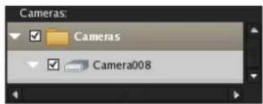
Specify the device for which to search. Only one device and channel can be selected.
Select the check boxes of the devices for which to search in the tree.
⑭Object Search Type
Select the type of motion detection for which to search.
⑤Object Search Settings
Click [Edit] to display the dialog box for the advanced configuration of search conditions in accordance with the motion detection type selected in [Object Search Type].
⑤Search Button
This performs a search with the specified conditions.
Setting Items of Object Search Configuration Dialog Box (VMD)
Specify the search conditions in detail for when searching with the motion detection function of VMD (recorder).
This dialog box is displayed when [VMF] is selected in the [Object] tab (page 119) of the Search window, and then [Edit] is clicked.
After configuring each item, click [OK].
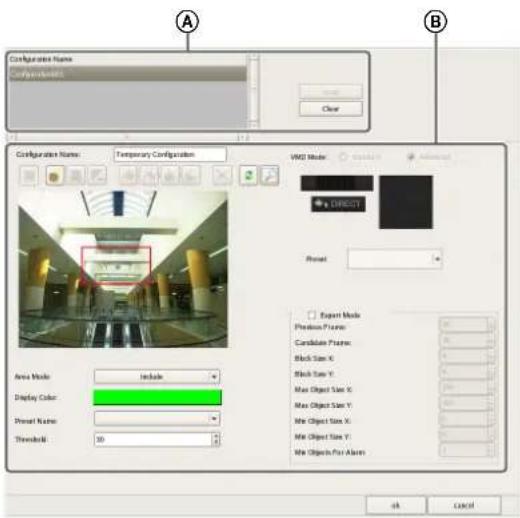
ⒶConfiguration Name
Select the configuration to use for the search, and click [Load].
The loaded settings are reflected in the items of “⑧.”
⑧Motion Detection Area Configuration Area
Configure the motion detection areas.
The configuration procedure is the same as that for [VMD (Recorder)] in the Device Configuration window. For details on each of the items, refer to "Setting Items of [VMD] Tab (VMD (Recorder))" (page 60).
Setting Items of Object Search Configuration Dialog Box (VMF)
Specify the search conditions in detail for when applying filters (VMF: Video Motion Filter) consisting of motion/object search conditions to search for the corresponding recordings.
This dialog box is displayed when [VMF] is selected in the [Object] tab (page 119) of the Search window, and then [Edit] is clicked.
After configuring each item, click [OK].
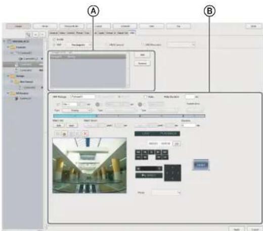
ⒶConfiguration Name
Select the VMF package to use for the search, and click [Load].
The loaded settings are reflected in the items of “⑧.”
⑧VMF Package Configuration Area
Configure the setting items of the VMF package. The configuration procedure is the same as that for [VMF] in the Device Configuration window. For details on each of the items, refer to "Setting Items of [VMD] Tab (VMF)" (page 67).
Search Results Display Area (List View)
In the list view, the list of search results is displayed. Depending on the item, you can click on a column title in the list to sort the list by the specified item. With each click, the sorting of the list switches between descending order and ascending order.
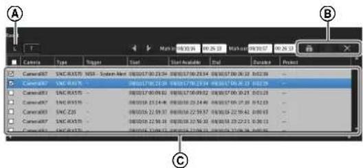
Ⓐ (List Mode)
This switches to the list view.
B (Protect)
This protects the selected recordings.

(Unprotect)
This cancels protection for the selected recordings.

(Delete)
This deletes the selected recordings.
©List of Search Results
When you want to playback recordings, select the check boxes of the corresponding cameras. The following information appears in the list.
Camera
Displays the camera name. This item can be sorted.
Type
Displays the type of the recording (Manual/Schedule/Alarm/Event). This item can be sorted.
Trigger
Displays the trigger of the recording. This item can be sorted.
Start
Displays the start time of the recording. This item can be sorted.
Start Available
Displays the start time from which playback is available.
Due to a cleanup or data overwrite, older data may be deleted in order from the beginning of recordings.
End
Displays the end time of the recording.
Duration
Displays the length of the recording data.
Protect
Displays "Protect" when the recording data is protected.
Search Results Display Area (Timeline View)
In the list view, each type of recording in the list of search results is displayed in a different color.
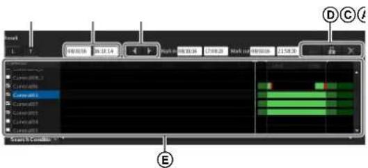
Ⓐ (Timeline Mode)
This switches to the timeline view.
⑧Time Indication of Timeline
This indicates the current position (time) on the timeline.
© (Mark In)/ (Mark Out)
You can specify the exporting of a part of a recording found in a search. Click (Mark In) or (Mark Out) to set the current playback position as the start point or end point. The mark in or mark out position can also be moved by dragging and dropping.
(D) (Protect)
This protects the selected recordings.

(Unprotect)
This cancels protection for the selected recordings.

(Delete)
This deletes the selected recordings.
EList of Search Results
When you want to playback recordings, select the check boxes of the corresponding cameras. The following information appears in the list.
Camera
Displays the name of the camera that made the recording.
White Line (Walker)
Indicates the current position (time) on the timeline. The white line can also be dragged to change its position. You can also move the white line by clicking the guide lines in the list title bar. (The white line moves to the position you click.)
When you want to playback recordings, select the check boxes of the corresponding cameras. The following information appears in the list.
Deleting Recorded Images
You can search for the recorded images you want to delete, and then delete them manually.
Note
To ensure disk space is always available, you can configure a schedule to delete recorded images. For details, refer to "Configuring Settings Related to Deleting Recording Data" (page 73).
1 Click Search for Recording Data) at the top of the main screen.
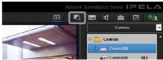
The Search Window appears.
2 Specify the search conditions, and click [Search].
For details on finding recorded images, refer to "Searching Recorded Images" (page 117).
3 Select the recorded images you want to delete, and click ✗ (Delete).
When List View
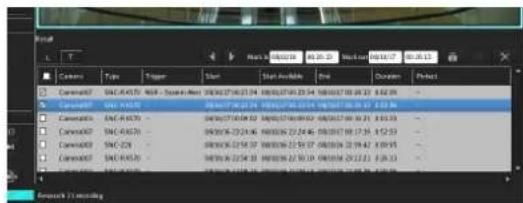
When Timeline View
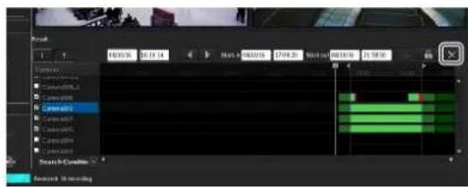
Note
Protected recorded images cannot be deleted.
A confirmation message appears.
4 Click [OK].
The recorded images are deleted.
Protecting Recorded Images
You can protect recorded images to prevent them from deletion by a cleanup, data overwrite, or unintentional operation.
1 Click Search for Recording Data) at the top of the main screen.
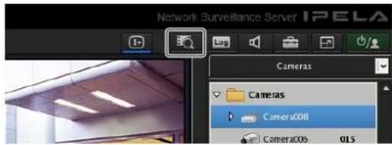
The Search Window appears.
2 Specify the search conditions, and click [Search].
For details on finding recorded images, refer to "Searching Recorded Images" (page 117).
3 Select the recorded images you want to protect, and click (Protect).
When List View
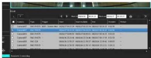
When Timeline View
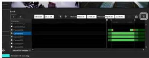
The recorded images are protected.
In the list view, "Protect" is displayed for protected recordings.
Cancelling Image Protection
Select the recorded images for which you want to cancel protection in Step 3 above, and click (Unprotect).
Exporting Recorded Images
You can export saved recorded images as files.
Video is exported in a native format (.cam file), and still images in JPEG format. Exported video can be played back with an application for playing CAM files.
Note
Multiple items cannot be exported at the same time.
Exporting Recorded Images
You can export saved recorded images as files. Export recorded images from the main screen or Search window. In the Search window, you can specify part of the recorded images to be exported.
Exporting from the Main Screen
1 Select any monitor frame, and display the camera images you want to export.
If you want to export recorded images that are currently playing, pause playback and then perform the procedure below.
2 Click Export Recorded Image) on the [Playback Control] pane.
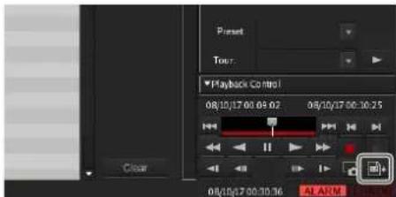
The Export dialog box appears.
3 Configure each item, and click [OK].
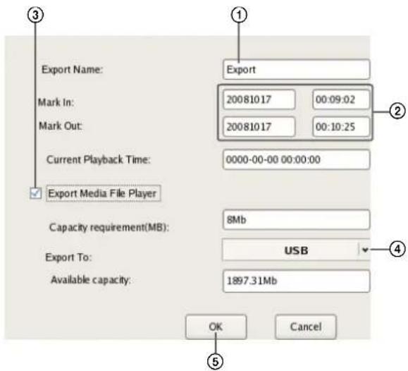
For details on each of the items, refer to "Setting Items of Export Dialog Box" (page 125).
①Enter the export name.
②Specify the start point (mark in) and end point (mark out) of the recorded images to export, as necessary.
③Select the check box to also export Media File Player for viewing the exported files.
④Select the media of the export location.
⑤Click [OK].
Exporting starts.
The following screen appears during exporting to allow you to confirm the progress.
Notes
- If there is insufficient free space on the media, a warning message appears and exporting stops.
- If you click [Close] during exporting, you can return to the main screen while continuing exporting.
- If you click [Abort], the export ends partway through, but the recorded images up until that point are exported.
-
If you click [Export Recorded Image) after returning to the main screen during exporting, the Exporting screen appears.
-
The space displayed for [Capacity Requirement] in the Export dialog box is just a rough indication. Even if the space displayed for [Available Capacity] exceeds that displayed for [Capacity Requirement], the space of the media may occasionally be insufficient, resulting in the export failing.
- If files that are currently recording are exported, they may not be able to be played back normally. When exporting recordings that are currently recording, export files other than the most recent file.
When exporting ends, the following screen appears.
4 Click [Close].
The Exporting screen closes.
Exporting from the Search Window
In the Search window, you can search for the recorded images you want to export, specify a start point (mark in) and end point (mark out), and then perform the export.
1 Click Search for Recording Data) at the top of the main screen.
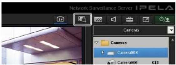
The Search Window appears.
2 Specify the search conditions, and click [Search].
For details on finding recorded images, refer to "Searching Recorded Images" (page 117).
3 Click to select the recorded images you want to export in the list of search results.
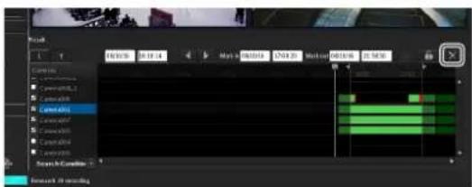
4 Switch to the timeline view, specify the start point (mark in) and end point (mark out), and then perform the export.
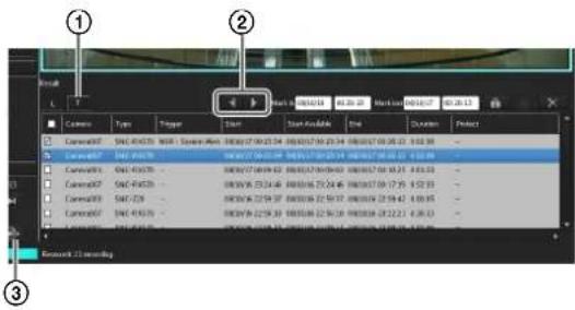
①Click (Timeline) to switch to the timeline view.
②Specify the start point (mark in) and end point (mark out) on the timeline. Click ▼Mark In) or (Mark Out) to set the current playback position as the start point or end point. The mark in or mark out position can also be moved by dragging and dropping.
③Click (Export Recording Data).
The Export dialog box appears. The subsequent procedure is the same as Step 3 of “Exporting Recorded Images” (page 124).
Setting Items of Export Dialog Box
This dialog box is displayed by clicking export Recorded Image) on the main screen (page 107). After configuring each item, click [OK].
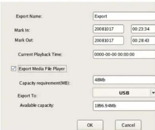
Export Name
Enter the export name.
Mark In
Enter a start point for the recorded images to be exported. You can also set a start point on the timeline of the Search window. If a mark in is set on the timeline of the Search window, that value is displayed automatically. You can adjust the value manually, as necessary.
Mark Out
Enter an end point for the recorded images to be exported. You can also set an end point on the timeline of the Search window. If a mark out is set on the timeline of the Search window, that value is displayed automatically. You can adjust the value manually, as necessary.
Current Playback Date and Time
This displays the date and time that the image currently displayed in the monitor frame was recorded.
Export Media File Player
Select the check box to also export Media File Player for viewing the exported files.
Capacity Requirement
This displays the space required for exporting the specified recorded images.
Location
Select the media of the export location.
Available Capacity
This displays the free space of the output location.
OK
This starts exporting.
Cancel
This cancels exporting, and closes the dialog box.
Exporting Recorded Images as Still Images
You can capture one scene of recorded or live images and export it as a still image file.
1 Select any monitor frame, and play the recorded images containing the scene you want to export.
2 Pause playback at the scene you want to export.
3 Click Capture Still Image) on the Playback Control pane.
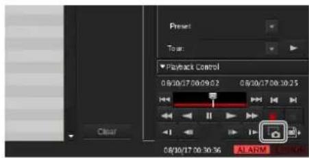
The Still Image Export dialog box appears.
4 Configure each item, and click [OK].
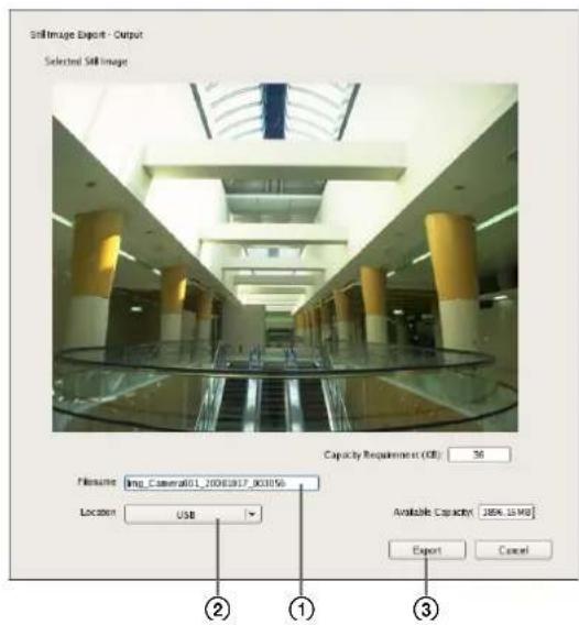
For details on each of the items, refer to "Setting Items of Still Image Export Dialog Box" (page 127).
①Enter the file name.
②Select the media of the export location.
③Click [Export].
The still image is exported.
Note
If there is insufficient free space on the media, a warning message appears and exporting stops.
Setting Items of Still Image Export Dialog Box
This dialog box is displayed by clicking Capture Still Image) on the Main screen. After configuring each item, click [OK].
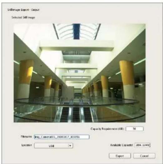
File Name
Enter the file name.
If a file with the same name as the file name entered already exists at the export location, the file may be exported under a different file name.
Location
Select the output location for the export file.
Free (MB)
This displays the free capacity of the output location.
System Administration
This section describes the operations necessary for routine system administration.
- "Shutting Down and Restarting the NSR" (page 30)
- "Monitoring the Error Status" (page 127)
- "Exporting Log Files" (page 128)
Monitoring the Error Status
When an error occurs with NSR, you can confirm the error with the ERROR lamp in the main screen or on the front of NSR.
The ERROR Lamp on the Main Screen
When a major hardware or software error is detected, the ERROR lamp at the bottom right of the main screen lights.
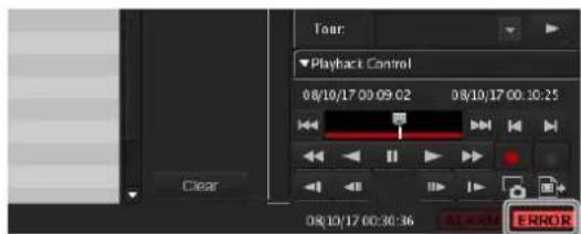
Confirming the Error Content
You can view the log by clicking the ERROR lamp to display the Log dialog box.
You can also view the log by performing the following.
1 Click at the top of the main screen.
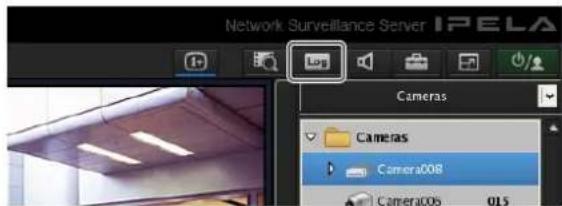
The Log dialog box appears.
2 Confirm the error content.
Select System, Event/Alarm, or Operation from [Log Type].
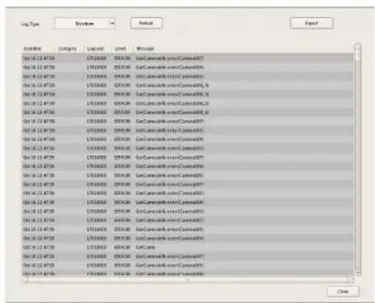
When an Error Occurs with the Hardware
The ERROR lamp on the front of NSR lights or flashes.
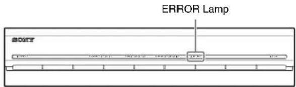
Confirming the Error Content
Refer to "STATUS LED" (page 132).
Exporting Log Files
You can export the following log files.
- System logs
• Event and alarm logs - Operation logs
1 Click at the top of the main screen.
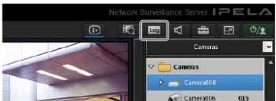
The Log dialog box appears.
2 Click [Export].
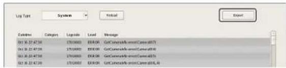
The Export dialog box appears.
3 Specify the logs you want to export, and click [OK].
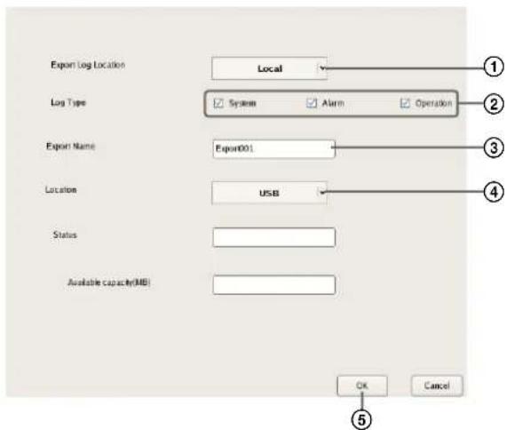
①Select the location in which to save the logs.
②Select the check boxes of the logs to export.
③Enter the file name.
④Select the media of the export location.
⑤Click [OK].
Exporting starts.
The following screen appears during exporting to allow you to confirm the progress.
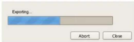
Notes
- If there is insufficient free space on the media, a warning message appears and exporting stops.
- If you click [OK] during exporting, you can return to the main screen while continuing exporting.
- The space displayed for [Capacity Requirement] in the Export dialog box is just a rough indication. Even if the space displayed for [Available Capacity] exceeds that displayed for [Capacity Requirement], the space of the media may occasionally be insufficient, resulting in the export failing.
When exporting ends, the following screen appears.
4 Click [Close].
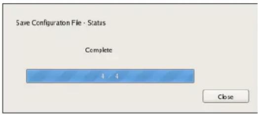
The Export screen closes.
I/O Port
Pin Assignment of I/O Port
Sensor In
| Pin NO. | SENSOR IN | ||||
| 1 | 3 | . | 3 | v | |
| 2 | I | N | - | 8 | - |
| 3 | I | N | - | 8 | + |
| 4 | I | N | - | 7 | - |
| 5 | I | N | - | 7 | + |
| 6 | I | N | - | 6 | - |
| 7 | I | N | - | 6 | + |
| 8 | I | N | - | 5 | - |
| 9 | I | N | - | 5 | + |
| 10 IN_4- | |||||
| 11 IN_4+ | |||||
| 12 IN_3- | |||||
| 13 IN_3+ | |||||
| 14 IN_2- | |||||
| 15 IN_2+ | |||||
| 16 IN_1- | |||||
| 17 IN_1+ | |||||
| 18 GND | |||||
Alarm Out
| Pin NO. | ALARM OUT | |||||
| 1 | GND | |||||
| 2 | O | U | T | - | 8 | - |
| 3 | O | U | T | - | 8 | + |
| 4 | O | U | T | - | 7 | - |
| 5 | O | U | T | - | 7 | + |
| 6 | O | U | T | - | 6 | - |
| 7 | O | U | T | - | 6 | + |
| 8 | O | U | T | - | 5 | - |
| 9 | O | U | T | - | 5 | + |
| 10 OUT_4 - | ||||||
| 11 OUT_4 + | ||||||
| 12 OUT_3 - | ||||||
| 13 OUT_3 + | ||||||
| 14 OUT_2 - | ||||||
| 15 OUT_2 + | ||||||
| 16 OUT_1 - | ||||||
| 17 OUT_1 + | ||||||
| 18 GND | ||||||
RS-422/485
| Pin NO. | RS-422 RS-485 | |
| 19 TX- | TX- | |
| 20 TX- | TX+ | |
| 21 RX- | ||
| 22 RX+ |
Using the I/O Receptacle
Insert a small slotted screwdriver into the upper or lower slot of the hole you want to connect a wire to (AWG No. 26 to 20). Hold down the screwdriver and insert the wire, then release the screwdriver.
Caution
Do not use excessive force when inserting the screwdriver into the slot. Doing so may result in damage.
①
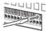
②
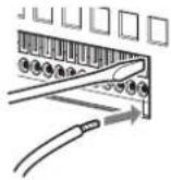
③
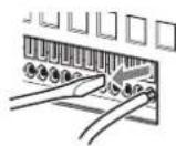
Repeat this procedure to connect all required wires.
Wiring Diagram 1 for Sensor Input
Inside of this unit Outside
3, 5, 7, 9, 11, 13, 15, 17pin (SENSOR IN+)
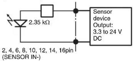
Wiring Diagram 2 for Sensor Input
Inside of this unit Outside
1 pin (VDD) (200 mA max)
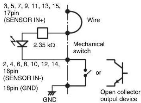
Note
When the wiring diagram 2 is used, the NSR is not electrically isolated, so be sure to construct external circuits that will not produce noise, excess voltage, or overcurrents.
Wiring Diagram for Alarm Output
Inside of this unit Outside
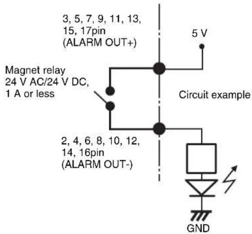
STATUS LED
When an error occurs with the unit, the ERROR LED on the front panel of the unit flashes or lights depending on the error status, and the STATUS LED lights.
1 2 3 4 ERRORSTATUS
The STATUS LED indicates the following error situations.
Error codes displayed during boot stage
(The ERROR LED blinks when an error occurs during boot.)
| Error code | STATUS LED | ERROR LED | Possible Cause | |
| 1 | 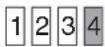 |  |  | Voltage power supply failure |
| 2 | 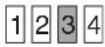 | [0727] | [2TKS] | CPU fan failure |
| 3 | [2DDT] | [2856] |  | Defective memory module |
| 4 |  |  |  | CMOS battery failure |
| 5 |  | [35HO] |  | Video random access memory (RAM) or controller failure |
| 6 | [Y480] |  | [5T50] | Hard disk controller failure |
| 7 | [0X0X] | [KDWB] |  | No bootable device found |
| 8 |  | [770A] |  | No bootable Operating System found |
| 9 | [52X0] | [4KXW] |  | One or more hard disk failure |
| A | [C0ZX] |  |  | RAID OS volume failure |
| B |  | [AT6A] |  | Failure to start the X11 server |
| C | [A036] | [2H62] |  | Failure to start the application |
| D | 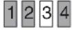 |  |  | Reserved for future use |
| E | 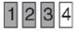 | [2643] |  | Reserved for future use |
| F |  |  |  | RAID data volume failure |
Error codes displayed during operation stage
(The ERROR LED lights when an error occurs during operation.)
| Error code | STATUS LED | ERROR LED | Possible Cause |
| 1 | 1 2 3 4 | On | Critical temperature |
| 2 | 1 2 3 4 | On | CPU fan failure |
| 3 | 1 2 3 4 | On | Power supply fan failure |
| 4 | 1 2 3 4 | On | Voltage power supply failure |
| 5 | 1 2 3 4 | On | Hard disk drive fan 1 failure |
| 6 | 1 2 3 4 | On | Hard disk drive fan 2 failure |
| 7 | 1 2 3 4 | On | Hard disk drive is damaged. |
| 8 | 1 2 3 4 | On | Reserved for future use |
| 9 | 1 2 3 4 | On | Reserved for future use |
| A | 1 2 3 4 | On | Reserved for future use |
| B | 1 2 3 4 | On | Operating system error |
| C | 1 2 3 4 | On | Application functioning failure |
| D | 1 2 3 4 | On | [ERROR] lamp in “Main” screen is lit |
| E | 1 2 3 4 | On | RAID data volume failure |
| F | 1 2 3 4 | On | RAID data volume is being restructured |
indicates that the STATUS LED or ERROR LED is lit.
Troubleshooting
Before contacting your retailer or a Sony Support Center, please check the following items. If the problem persists, contact them.
The NSR does not work.
- Verify that the power switch is turned on.
- Verify that the power cable is connected correctly.
- Make sure the wall outlet has power. Test it by plugging another device.
- Verify that the hard disk drives are not being accessed (the HDD LEDs on the front of the recorder do not blink), and then turn it off forcibly by pressing and holding the power switch at the rear of the unit for approximately 10 seconds. Restart the NSR.
- During the startup procedure, the NSR checks the file system. The length of this check varies depending on the amount of data on the NSR (in some extreme case, it can take as long as two hours). During the file system check, the HDD LEDs on the front of the recorder blink.
- If the NSR does not start correctly, the following screen may appear.
NSR DOM Menu
- HDD Restore
- DOM Restore
- Software Restore
- Reboot the system
- Shutdown the system
Enter your choice :
When it does, proceed as follows.
- Select "5. Shutdown the system," and press the Enter key.
- Referring to “Cannot access the hard drive.”, verify whether the NSR hard disks are correctly connected.
- Restart the NSR and verify whether it starts.
The monitor remains blank.
- Verify whether the NSR is on.
- Verify whether the power cord is correctly connected.
- Verify whether the monitor cable is correctly connected. Confirm that the monitor is connected to monitor connector 1.
- If you configure the wrong monitor resolution, the “Out of range” message may appear when the monitor resolution is too low compared to the monitor output. Press CTRL+ALT+MINUS SIGN as many times as necessary to lower the resolution of the output video. When the output image resolution reaches the resolution of the monitor, the image appears. Subsequently, reconfigure your monitor resolution. For details, refer to the User’s Guide (PDF).
The monitor connected to the HDMI connector does not display properly.
- If you switch the input for the HDMI monitor or reconnect the cable, images may not display properly in some cases. In such cases, try the following.
- Switch the input for the monitor.
- Restart the monitor.
Note
If the problem persists after performing the above, disconnect the HDMI cable and continue operation with the analog RGB monitor. When it is convenient to stop operation, restart the unit and try reconnecting the HDMI monitor.
The new external hardware is not working properly.
- Make sure the cables for the new external device are firmly connected and the pins are not bent.
An external device connected to a USB connector does not work.
- When you connect a USB device to the unit, the [ERROR] lamp at the bottom right of the “Main” screen may light. Perform the following to confirm whether the unit supports the USB device.
- Click the [ERROR] lamp. The System Log appears.
-
Confirm whether the “Unsupported USB device” error appears in the System Log. If “Unsupported USB device” appears, the unit does not support the USB device.
-
This unit supports standard USB 2.0 Mass Storage devices. Depending on the type of USB 2.0 Mass Storage device, however, errors may occur when writing data to the device. If errors occur when writing data, use a USB memory device of a different type.
- To ensure proper operation of USB devices, do not connect the devices via a USB hub. Connect the devices directly to the USB connectors on the unit. Operation is not guaranteed when devices are connected via a USB hub, USB switch, or extension cable.
- Refer to the documentation that came with the USB device.
System cannot read the DVD/CD information.
- Make sure that you are using the correct type of disc.
- Make sure the DVD/CD is properly inserted in the drive.
- Check if the DVD/CD is clean and not scratched.
The DVD/CD tray cannot be ejected.
- Make sure that the NSR is turned on.
- Slowly insert the tip of a pen or paperclip into the eject hole on the DVD/CD drive. Pull the tray out from the drive then remove the disc.
The NETWORK LED does not light up.
- Check the cabling and network equipment for the proper connection.
Cannot access the hard disk drive.
- Make sure the hard disk drive is properly inserted.
- Check the HDD LEDs on the front panel of the system. When a hard disk malfunctions, the LED of the corresponding hard disk lights in amber.
- Due to rapid flashing during frequent access to the hard disk drive, the HDD LED may appear unlit in bright environments.
Cannot access NSR from a remote client.
- Make sure the NSR is operating properly (there should be no abnormalities with the hard disk drive, network, software or other items).
- Make sure that the central server settings for the unit are correct.
- Make sure the correct user name, password, and connection port are set in RealShot Manager Advanced.
- Refer to the troubleshooting section of the user's guide for the RealShot Manager Advanced.
The NSR heats up quickly
- Make sure that nothing is blocking the ventilation openings on the front, sides, and rear of the unit and dust has not accumulated in them.

Specifications
NSR-1200/1100/1050H
Processor
CPU NSR-1200: Quad Core Xeon NSR-1100: Dual Core Xeon NSR-1050H: Dual Core Xeon
Memory
Onboard flash memory 4 GB
Internal memory
NSR-1200: 2 GB
NSR-1100: 1 GB
NSR-1050H: 1 GB
Recording devices
Internal hard disk drive
NSR-1200: 2 TB
(SATA-II 500 GB × 4)
NSR-1100: 1 TB
(SATA-II 500 GB × 2)
NSR-1050H: 500 GB
(SATA-II 500 GB × 1)
Capacities for hard disk drives are based on the following equation for 1 GB: 1,000 × 1,000 × 1,000 = 1 billion bytes
DVD/CD drive (front) 1 drive
Compatible media: DVD+R, DVD-R, DVD-ROM, CD-R, CD-RW, CD-ROM
External connectors
Front Monitor output:
Analog RGB (mini D-SUB 15 pin) (1) USB: USB 2.0 (3)
Rear Monitor output:
Analog RGB (mini D-SUB 15 pin) (2) HDMI (2)
Audio output (L) (1)
Audio output (R) (1)
Audio input (1)
LAN (1000Base-T/100Base-TX/10Base-T) (RJ-45) (4)
USB: USB 2.0 (3)
Mini-SAS output (for optional NSRE-S200 connection, mini-SAS ×4 (SFF-8088), 3.0 Gbit/s) (1)
Sensor input (compatible with 3.3 V to 24 V DC devices, photo coupler input, insulated from main unit) (8)
Alarm output (maximum 24 V DC, 1 A, mechanical relay output, insulated from main unit) (8)
UPS serial: RS-232C (1)
Analog camera control (only with NSR-1050H or NSBK-A16 expansion):
RS-232C (1)
RS-422/485 (1)
Operating environment
Operating temperature
5^ to 40^ (41°F to 104°F)
Operating humidity
20% to 80% (maximum wet-bulb temperature: 30 °C, noncondensing)
Temperature range for storage
-20 to +60 °C (-4 to +140 °F)
Humidity range for storage
20 to 90% relative humidity (maximum wet-bulb temperature 35 ^/95 ^ , no condensation)
Power and miscellaneous
Power
100 to 127 V AC/200 to 240 V AC (50/60 Hz)
Power consumption
Max. 350 W
Dimensions
430 × 87 × 417 mm (16.9 × 3.4 × 16.4 in.) (W/H/D, excluding protrusions)
Mass
NSR-1200: approx. 13.5 kg (29.8 lb.)
NSR-1100: approx. 12 kg (26.7 lb.)
NSR-1050H: approx. 11.5 kg (25.4 lb.)
Optional accessories
NSR-RM1 Rack Mounting Kit
NSBK-A16 Analog Encoder Kit
NSRE-S200 Expansion Storage Unit
Design and specifications are subject to change without notice.
Notes
• Always make a test recording, and verify that it was recorded successfully. SONY WILL NOT BE LIABLE FOR DAMAGES OF ANY KIND INCLUDING, BUT NOT LIMITED TO, COMPENSATION OR REIMBURSEMENT ON ACCOUNT OF FAILURE OF THIS UNIT OR ITS RECORDING MEDIA, EXTERNAL STORAGE SYSTEMS OR ANY OTHER MEDIA OR STORAGE SYSTEMS TO RECORD CONTENT OF ANY TYPE.
• Always verify that the unit is operating properly before use. SONY WILL NOT BE LIABLE FOR DAMAGES OF ANY KIND INCLUDING, BUT NOT LIMITED TO, COMPENSATION OR REIMBURSEMENT ON ACCOUNT OF THE LOSS OF PRESENT OR PROSPECTIVE PROFITS DUE TO FAILURE OF THIS UNIT, EITHER DURING THE WARRANTY PERIOD OR AFTER EXPIRATION OF THE WARRANTY, OR FOR ANY OTHER REASON WHATSOEVER.
Index
A
Action 92
Administration Menu 12
Alarm Output 89
Alarm Recording 81
Analog Camera 48
Audio 16,49
Automatic Camera Registration 33, 77
C
Camera Auto Registration 34
Camera Control 114
Camera Tours 45, 115
Cleanup 74
Click Action 55,112
Codec 43, 44
Configuration Data 22
Control 48
Current Consumption 11
D
Data Overwriting 73
Date and Time 13
Deleting Recorded Images 122
Deleting Recording Data 73
Device Configuration 33
Disk Menu 16
E
ERROR Lamp 127, 128
Error Status 127
Event Recording 81
Event/Alarm Actions 95
Export System Information 24
Exporting 24
Exporting Log Files 128
Exporting Recorded Images 124
F
Features and Functions 8
Frame Rate 43, 44
FTP 17
G
GUI Configuration 104
|
I/O Port 130
Inrush Current 11
K
Keyboard 13
L
Language 13
Layout Configuration 52
Layout Tours 58, 106
Locking the NSR 30
Log Files 128
Logging Off 29
Logging On 25
M
Mail Notification 98
Main Screen 107
Manual Action 92
Masks 46
Metadata 65
Monitor Layout 50
Monitor Menu 15
Monitoring 105
Monitoring Audio 106
Motion Detection 59
Multiple Camera Registration Dialog Box 40
N
Network Device Menu 14
Number of Cameras 11
0
Object Detection 59
P
Password 29
Patch Files 21
Patch Installation 21
Permissions 101
Playing 116
Preset Positions 44
Presets 115
Protecting Recorded Images 123
PTZ 114
Q
Quick Playback 104
R
Reboot 30
Recording 116
Recording Duration Guide 11
Reference Data for Installation 11
Registering Devices 33
Registering Users 101
Resolution 43, 44
Restarting 30
Restore Configuration 23
s
SAS Disk 17
Save Configuration 22
Schedules 77
Searching 116
Second Monitor 57
Sensor Inputs 86
Serial Port (Analog Camera) 19
Server Configuration 20
Server Name 18
Setup Menu 13
Shutdown 30
SNMP Menu 18
Specifications 135
STATUS LED 132
Still Images 126
Storage 70
Storage Capacity for Recorded Data 11
System Alert 99
System Information 24
T
Tour 45
Troubleshooting 133
U
UPS 19
User Levels 101
V
Version Information 31
Video 43
Video (Analog Camera) 20
Video Motion Filter 65
VMD (Camera) 62
VMD (Recorder) 60
VMF 65
Volume 106

- Network Surveillance Server
- Table of Contents
- Chapter 1 Introduction
- Chapter 2 Administration Menu
- Chapter 3 Basic Operation
- Chapter 4 Application Settings
- Configuring Alarm Output Settings 89
- Configuring Action Settings 92
- Configuring Mail Notification Settings 98
- Configuring System Alert Settings ....99
- Registering Users ....101
- Configuring the Duration to Rewind for Quick Playback.....104
- Chapter 5 Operation and Control
- Monitoring ....105
- Controlling Cameras ....114
- Recording, Searching, and Playing Images ....116
- Deleting Recorded Images....122
- Chapter 6 Appendix
- For the State of California, USA only
- For the customers in Taiwan only
- 廢電池請回收
- Trademarks
- Introduction
- Chapter
- 1
- Overview
- Note
- Control compatible cameras from remote locations
- Compatible with analog cameras
- Large-capacity hard disks allow recording for long periods of time
- Slim type (2U), space-saving 19-inch rack mounting model
- High-resolution up to 480 fps (VGA, JPEG) recording
- High reliability
- Other features
- Features and Functions
- Front (When the Cover is Opened)
- Power LED
- Network LED (1 to 3)
- HDD LED
- Status LED (1 to 4)
- Error LED
- REC LED
- DVD/CD drive
- 8USB connector
- 9Monitor connector 1
- Power switch
- 11Lock
- Vent holes
- Rear
- Fan
- Power switch
- ③RS-232C Connector
- UPS connector (RS-232C)
- Sensor input connector
- Alarm output connector
- System Requirements
- Reference Data for Installation
- Storage Capacity for Recorded Data
- Number of Cameras
- Administration Menu
- 2
- Displaying the Administration Menu
- Changing Initial Settings with the Setup Menu
- Displaying Setup Menu
- Details on Setting Items
- Setting Items of Language Screen
- Setting Items of Keyboard Screen
- Setting Items of Date and Time Screen
- Year/Month/Day
- Hour/Min
- Date Format
- Enable NTP Server
- Synchronize with NTP Server
- IP Address
- Synchronize with Windows Server
- Current Synchronization
- Time Zone
- Setting Items of Network Device Menu Screen
- Caution
- ■Setting Items of General Network Screen
- Primary DNS
- Secondary DNS
- Default Gateway
- Hosts
- ■Setting Items of Network Device 1 to 3
- Netmask
- Route Setting
- Setting Items of Monitor Menu Screen
- ■Setting Items of Monitor 1 to 2
- Setting Items of Audio Screen
- Setting Items of Disk Menu Screen
- ■Setting Items of Disk Installation Screen
- ■Setting Items of Internal Disk Partition Screen
- Capacity
- Number of Partitions
- Partition1 [data1-1]
- ■Setting Items of SAS Disk List Screen
- ■Setting Items of SAS Disk Partition Screen
- ■Setting Items of Disk Uninstallation Screen
- Setting Items of FTP Screen
- Enable user to Get Data from Remote
- User Name
- Password
- Enable user to Get Tools from Remote
- Setting Items of Server Name Screen
- Setting Items of SNMP Menu Screen
- ■Setting Items of SNMP Agent Screen
- Enable
- Disable
- Community
- Contact
- Location
- ■Setting Items of SNMP Traps Screen
- Host IP Address
- Shutdown Events
- Temperature Events
- Voltage Events
- Fan Events
- UPS Events
- Power Events
- HDD Events
- RAID Events
- File System Event
- Network Events
- Resource Usage Events
- SAS Events
- Setting Items of UPS Screen
- Power off in XXX Seconds
- Setting Items of Serial Port (Analog Camera) Screen
- Baud rate
- Parity bit
- Character length
- Stop bits
- Setting Items of Video (Analog Camera) Screen
- Configuring Settings Related to Servers
- Central Server Mode
- Use Proxy Server
- Port
- Connection from Remote Client
- Network Interface for Remote Client
- Server Port
- Central Server
- Event Action Server
- Download Server
- Record Server
- Installing Patch Files
- Saving and Restoring Configuration Data
- Saving Configuration Data
- Click [Close].
- Restoring Configuration Data
- Click [Restore Configuration] in the Administration Menu.
- Select the location where the configuration data is saved and the configuration data, and click [OK].
- Click [OK].
- Click [OK].
- Exporting System Information
- Logging On to the NSR
- Basic Window Operations
- Main screen
- Configuration screen
- Changing the Password
- Notes
- Logging Off
- Locking the NSR
- Shutting Down and Restarting the NSR
- Viewing Version Information
- Application Settings
- 4
- Alarms and Events
- Displaying Configuration Window
- Registering Devices
- Selecting Automatically Detected Cameras and Registering Them Simultaneously
- Registering Devices Manually
- When registering a camera server (SNT series, etc.):
- Changing Registration Details
- Deleting Devices
- Settings Required when Using SNC-CS20/CM120/DS10/DM110/DS60/DM160
- Flow when Using SNC-CS20/CM120/DS10/DM110/DS60/DM160
- Click [Select Camera Function] on the [Function Selection] tab of the Device Configuration screen.
- Select the function combination one line at a time in order from the top left, and click the [OK] button.
- Configure the other items on the [General] tab.
- Registering Device Groups
- Registering a Device Group
- Adding Devices to a Group
- Removing Devices from a Group
- Deleting a Group
- Details of Each Screen
- Setting Items of Device Configuration Screen
- ⒶTree Structure
- ⑧ (Camera Auto Registration)
- © (Add)
- (Delete)
- EDevice List
- Setting Items of the [General] Tab
- Name
- Type
- Global ID
- Proxy
- Preview
- Apply
- Cancel
- Setting Items of Multiple Camera Registration Dialog Box
- Network
- Reload
- Input All
- Show
- Unregistered Cameras
- Registered Cameras
- All Cameras
- Device List
- Register
- Model
- User
- Serial No.
- MAC Address
- Status
- Registration
- Setting Items of Input All Dialog Box
- Port No.
- OK
- Setting Items of Add Device Dialog Box
- Device Model
- Configuring Camera Video Settings
- Setting Items of [Video] Tab
- Video Channel
- E-Flip
- Audio Channel
- Schedule Record
- Codec
- Image Size
- Image Quality (for JPEG)
- Bit Rate (for MPEG4)
- Frame Rate
- Alarm/Event Record
- Monitoring
- Light Funnel
- Threshold
- Hold Time
- Configuring Camera Operations
- Configuring Preset Positions
- Configuring a New Preset Position
- Changing Preset Settings
- Deleting Presets
- Configuring Camera Tours
- Setting a New Tour
- Configure each item.
- Camera Tour Operation
- Changing Settings
- Configuring Masks
- Setting Items of [Masking] Tab
- ©Data
- ⑤Pan, Tilt, and Zoom Toolbar
- ©Preview Area and Tool Buttons
- (Create/Move Area)
- (Edit Points)
- (Add Point)
- (Remove Point)
- (Bring to Front)
- (Bring Forward)
- (Send Backward)
- (Send to Back)
- (Remove Area)
- (Refresh Image)
- (Preview)
- ⑧Apply
- ①Cancel
- Configuring Control Protocol of Analog Camera
- Configuring Network Camera Control
- Click [Device] at the top of the Configuration window.
- Select the network camera, and click the [Control] tab.
- Select the [Auto Pan & Tilt Speed] check box, and click [Apply].
- Configuring Audio
- Select the camera for which to enable audio, and click the [Audio] tab.
- Configure each item, and click [Apply].
- Settings Related to Monitoring
- Configuring Monitor Layout Settings
- Creating a New Layout
- Deleting Layouts
- Setting Items of Layout Configuration Screen
- Ⓐ[Layout] Tree
- + (Add)
- - (Delete)
- BName
- ©Show on the Main Window
- ©Hotspot
- ©Insert Background Image
- ⑤Apply Template
- ©Tool Buttons
- (Insert Image)
- (Insert Image Map)
- (Remove Item)
- (Remove Assigned Cameras)
- (Flip)
- (Spin)
- (Grid)
- ©Monitor Frame
- ①Actual Size/Adjust to Window Size
- ①Properties Tabs
- ©[Device] Tree
- MCancel
- Setting Items of Properties
- ■ When a monitor frame is selected:
- • [ General ] Tab
- Server
- Camera
- • [Display Information] Tab
- Camera Name
- Time
- Display Image per Second
- Bandwidth
- VMD (Recorder)
- VMF
- Object Frame
- Alarm Object Frame
- Filter Frame
- Inactive Area Frame
- Object ID
- Object Duration
- Filtered Count
- Apply to All Monitor Frames
- • [ Options ] Tab
- Scale to Monitor Frame
- Keep Aspect Ratio
- Smooth Scaling
- Restrict the display image per second
- ■When an image or image map is selected:
- File Name
- Reload Original Size
- Transparent Color
- • [Action] Tab
- Click Action
- • [Select Camera] Tab
- Camera Select
- Monitor Frame
- Setting Items of Insert Template Dialog Box
- Layout
- Columns
- Rows
- Merge Rows and Columns
- Setting Items of Insert Background Image Dialog Box
- Color
- Image
- Stretch
- Center
- Setting Items of Insert Image Dialog Box
- Assigning Cameras to Monitor Frames
- Configuring a Second Monitor
- Configure each item.
- Click [Apply].
- Configuring Layout Tours
- Creating a New Layout Tour
- Select "Layout Tour" from the [Layout] tree on the Layout Configuration screen, and click (Add).
- A layout tour is added to the tree.
- Create a layout tour.
- Deleting Layout Tours
- Configuring Motion Detection Settings
- About Motion Detection and Object Detection
- What is Motion Detection?
- What is Object Detection?
- What is Motion Detection by Camera Image Metadata?
- Using the Motion Detection Function of NSR (VMD (Recorder))
- Setting Items of [VMD] Tab (VMD (Recorder))
- ⒶEnable
- ⑧Type of Motion Detection Function
- ©Area Configuration List
- Add
- Delete
- Configuration Name
- E VMD Mode
- ©Image Controls
- ©Preview
- (Move Polygon)
- (Edit Point)
- (Remove Polygon)
- ①Area Mode
- Display Color
- Preset Name
- ①Expert Mode
- Previous Frame
- Candidate Frame
- Block Size X
- Block Size Y
- Max Object Size X
- Max Object Size Y
- Min Object Size X
- Min Object Size Y
- Min Objects For Alarm
- ©Apply
- LCancel
- Using the Motion Detection Function of the Camera (VMD (Camera))
- Setting Items of [VMD] Tab (VMD (Camera))
- ©Pulse
- Pulse Duration
- ⑤Camera Position
- Current Position
- Preset Position
- Object Type
- - When Moving:
- - When Unattended:
- Detection Time
- Area 1 to Area 4
- Minimum Detectable Object Size
- Maximum Detectable Object Size
- HCancel
- Detecting Motion by Metadata (VMF)
- Setting Items of [VMD] Tab (VMF)
- ©VMF Package List
- DSequential
- Parallel
- ⑤Inactive Area Frame
- © (Preview)
- ⑧Package Name
- ■For "Moving" packages
- Appearance
- Disappearance
- Existing
- Passing
- ■For "Unattended" packages
- Unattended/Removed
- Duration
- ①Tool Buttons
- ©Object Size
- MIN
- MAX
- Object Speed
- ■Duration (When [Existing] and [Unattended/Removed] Filter Types)
- ■Capacity (When [Capacity] Filter Type)
- ■Collision (When [Passing] Filter Type)
- LPreview
- ®Apply
- ©Cancel
- Configuring Settings Related to Storage
- Configuring Storage Settings
- Adding New Storage
- Configuring Storage for Each Recording Type ([Record Type] Mode)
- Configuring Storage for Each Camera ([Camera] Mode)
- Setting Items of the [Storage] Tab
- ⒶStorage List
- Free (%)
- Free
- Total
- B (Add Storage)
- © (Delete Storage)
- DName
- ©Location
- ©Overwrite
- Not to be less than
- Setting Items of [Storage Assign] Tab
- ⒶStorage Mode
- Record Type
- ■To assign storage for each recording type
- ⑧Record Type and Storage
- Manual Record
- Alarm Record
- Event Record
- ®Default Storage
- ©Storage for Each Camera and Record
- All Record Type
- ECancel
- Configuring Settings Related to Deleting Recording Data
- • Data Overwriting (page 73)
- - Cleanup (page 74)
- - Deleting Manually (page 122)
- Data Overwriting
- Cleanup
- Setting Items of the [Data Cleanup] Tab
- ⑧Execution Time
- ©Input All
- ©Cleanup Setting List
- Target
- Manual Record (days)
- Schedule Record (days)
- Alarm Record (days)
- Event Record (days)
- ⑤Cancel
- Storage Configuration Example
- Screen example: When NSRE-S200
- Configuring Recording Schedules
- - Schedule Recording (Normal Recording)
- - Alarm Recording
- - Event Recording
- - Configuring Schedules with Automatic Camera Registration (page 77)
- - Configuring Schedules Manually (page 79)
- - Configuring Alarm Recording/Event Recording (page 81)
- Record Segmenting in Continuous Long-term Recording
- Configuring Schedules with Automatic Camera Registration
- Configuring Schedules Manually
- Configuring Recurrent Schedules
- Configuring a Schedule for a Specific Date and Time
- Configuring Alarm Recording and Event Recording
- Deleting a Schedule
- About Relationship Between Sensor and Camera when Alarm Occurs
- When [Record by each event]:
- When [Record by selected event]:
- Setting Items of Schedule Screen
- Ⓐ[Schedule] Tree
- ⑧Recurrent/Date and Time View Selection Button
- Recurrent
- Date Time
- ©New Record
- ©Auto Record
- ECommon Schedule Display
- ⑤Schedule View
- When recurrent view:
- When date and time view:
- ©Edit
- ⑧Remove
- ①Show Configuration Information
- ①Apply
- Setting Items of New Record Dialog Box
- ©Enable
- DSchedule
- When recurrent schedule:
- When schedule for a specific date and time:
- ©Record Duration
- Record Start
- Event Start
- Pre Event Start
- Record End
- From Event Start
- From Even End
- ⑤Associate recording data with alarm
- ©Event
- Record by each event
- Record by selected event
- HTarget Camera
- Add Device
- Camera List
- Adjust to Camera Settings
- ①OK
- JCancel
- Configuring Sensor Inputs
- Examples of sensor inputs:
- Changing Settings of Sensor Input Pins of NSR
- Changing Settings of Sensor Input Pins of Camera
- Changing Settings of Sensor Input Pins of Barionet
- Adding Logical Sensor Input Pins to NSR
- Deleting Logical Sensor Input Pins Created for NSR
- Setting Items of the [Logical Sensor In] Tab
- Sensor Input Pin List
- No
- Pulse
- Invert
- Configuring Alarm Output Settings
- Example of Alarm Outputs:
- Changing Settings of Alarm Output Pins of NSR
- Changing Settings of Alarm Output Pins of Camera
- Changing Settings of Alarm Output Pins of Barionet
- Setting Items of the [Alarm Out] Tab
- [Alarm Out] Tab (IO Device)
- Alarm Output Pin List
- [Alarm Out] Tab (Camera)
- Configuring Action Settings
- Relationship Between Events and Actions
- Manual Action
- Registering a Manual Action
- Performing a Manual Action
- Setting Items of Manual Action Screen
- Show on the Main Window
- Register as OFF Action
- Number of Settings
- [Add Device] Button
- Camera Drop-down Menu
- Camera Control
- Preset
- Tour
- Action End Preset
- Pin List
- IO Device Drop-down Menu
- [System Action] Tab
- Send e-mail
- E-mail Address
- Attach Camera Image
- Each camera
- Specified Camera
- Message
- Change Layout
- Beep
- Event/Alarm Actions
- Event/Alarm Action Example:
- Registering an Event/Alarm Action
- Setting Items of New Action Dialog Box (Event/Alarm Action)
- Screen example: When recurrent event/alarm action:
- ⒶSchedule Action and Event/Alarm Action
- (D)Schedule
- When recurrent event/alarm action:
- When event/alarm action for a specific date and time:
- ©Action Duration
- Action Start
- Stop Action
- No Definition
- FServer
- IO Device
- System Alert
- ©Action
- Alarm Notification
- Action
- Configuring Mail Notification Settings
- Configuring System Alert Settings
- Setting Items of the [System Alert] Tab
- ⒶVIDEO LOSS
- ©Disk Usage
- Target Storage List
- Remaining Space
- ©Record Count
- Current/Max. Record Count
- Registering Users
- User Levels and Permissions
- Registering a User
- Changing User Settings
- Deleting a User
- Setting Items of the [User] Tab
- ⒶUser
- Confirm Password
- ®User Level
- ©Permission
- Search & Playback
- Export Control
- User Configuration
- Device Configuration
- ©Servers/Cameras Access
- Configuring the Duration to Rewind for Quick Playback
- Operation and Control
- 5
- Monitoring Live Images
- Monitoring Images of a Different Camera
- Changing the Layout
- Monitoring Using Layout Tours
- Monitoring Audio from Cameras
- Adjusting the Volume
- Functions and Operating Procedure of Main Screen
- Ⓐ[Layout] Toolbar
- (2×2 Layout)
- (3×3 Layout)
- (4×4 Layout)
- (Custom A Layout)
- (Custom B Layout)
- Layout Menu
- ⑧[Tour] Toolbar
- Tour Menu
- (Layout Tour Start/Stop)
- © (Display Information)
- (Search Recording Data)
- Log (Open Log Window)
- (Volume Control)
- (Configuration)
- (Full Screen)
- (Cancel Full Screen)
- ⑤Camera/Group/Manual Action Pane
- All Monitor Frames
- OPTICAL
- DIGITAL
- Wide-angle/Telephoto Zoom
- Pan/Tilt
- [Adjust] Tab
- Focus
- Brightness (EV)
- Day/Night
- ①Playback Control Pane
- Date and Time Indication
- (Rewind)
- (Reverse Play)
- II (Pause)
- (Play)
- (Fast Forward)
- (Slow Rewind)
- (Previous Frame)
- (Next Frame)
- (Slow Forward)
- (Previous Recording)
- (Next Recording)
- (Start Recording)
- (Stop Recording)
- (Capture Still Image)
- (Export Recorded Image)
- ①[ALARM] Lamp
- [ERROR] Lamp
- ©Expand/Collapse Pane Button
- ①Alarm History Pane
- Clear
- ©Monitor Frames
- When a Click Action is Configured
- Second Monitor (Monitor 2)
- Screen of Monitor 1 Screen of Monitor 2
- ⒶCamera Name
- BState
- ©Bandwidth
- (D)Frame Rate
- ©VMD (Recorder):
- ⑤Display Images per Second
- ©Time
- Switching a Monitor Frame to 1x1 View
- Controlling Cameras
- Performing Pan, Tilt, and Zoom Operations
- Using Camera Control Pane to Control Camera
- Using Mouse to Control Camera
- ■Centering the Image
- ■Performing Pan, Tilt, and Zoom Operations
- ■Performing Zooming In and Out Operations
- Using Camera Presets
- Performing Camera Tours
- Recording, Searching, and Playing Images
- Recording Live Images
- Playing Recorded Images
- Quick Playback
- Specifying a Date and Time and Playing
- Playing from Alarm History
- Searching Recorded Images
- - Normal Search
- - Object Search
- Normal Search
- Object Search
- When VMD (Recorder)
- When VMF
- Playing Recorded Images from Search Results
- Details of Search Window
- Setting Items of Search Window (Normal)
- Ⓐ[Normal] Tab
- ⑧Date and Time Specification Area
- ©Device Specification Area
- (D)Recording Type
- ESearch Button
- Setting Items of Search Window (Object)
- Ⓐ[Object] Tab
- ⑭Object Search Type
- ⑤Object Search Settings
- ⑤Search Button
- Setting Items of Object Search Configuration Dialog Box (VMD)
- ⒶConfiguration Name
- ⑧Motion Detection Area Configuration Area
- Setting Items of Object Search Configuration Dialog Box (VMF)
- ⑧VMF Package Configuration Area
- Search Results Display Area (List View)
- Ⓐ (List Mode)
- B (Protect)
- (Unprotect)
- (Delete)
- ©List of Search Results
- Trigger
- Start
- Start Available
- End
- Protect
- Search Results Display Area (Timeline View)
- Ⓐ (Timeline Mode)
- ⑧Time Indication of Timeline
- © (Mark In)/ (Mark Out)
- (Protect)
- EList of Search Results
- White Line (Walker)
- Deleting Recorded Images
- When List View
- When Timeline View
- Protecting Recorded Images
- Cancelling Image Protection
- Exporting Recorded Images
- Exporting from the Main Screen
- Click [Close].
- Exporting from the Search Window
- Click Search for Recording Data) at the top of the main screen.
- Specify the search conditions, and click [Search].
- Click to select the recorded images you want to export in the list of search results.
- Switch to the timeline view, specify the start point (mark in) and end point (mark out), and then perform the export.
- Setting Items of Export Dialog Box
- Export Name
- Mark In
- Mark Out
- Current Playback Date and Time
- Export Media File Player
- Capacity Requirement
- Available Capacity
- Exporting Recorded Images as Still Images
- Setting Items of Still Image Export Dialog Box
- Free (MB)
- System Administration
- Monitoring the Error Status
- The ERROR Lamp on the Main Screen
- Confirming the Error Content
- Confirm the error content.
- When an Error Occurs with the Hardware
- Exporting Log Files
- Click [Export].
- Specify the logs you want to export, and click [OK].
- I/O Port
- Pin Assignment of I/O Port
- Using the I/O Receptacle
- Wiring Diagram 1 for Sensor Input
- Wiring Diagram 2 for Sensor Input
- Wiring Diagram for Alarm Output
- STATUS LED
- Error codes displayed during boot stage
- Error codes displayed during operation stage
- Troubleshooting
- The NSR does not work.
- NSR DOM Menu
- The monitor remains blank.
- The monitor connected to the HDMI connector does not display properly.
- The new external hardware is not working properly.
- An external device connected to a USB connector does not work.
- System cannot read the DVD/CD information.
- The DVD/CD tray cannot be ejected.
- The NETWORK LED does not light up.
- Cannot access the hard disk drive.
- Cannot access NSR from a remote client.
- The NSR heats up quickly
- Specifications
- NSR-1200/1100/1050H
- Processor
- Memory
- Recording devices
- External connectors
- Operating environment
- Power and miscellaneous
- Optional accessories
- Index
- A
- C
- D
- E
- F
- G
- |
- K
- L
- M
- N
- 0
- P
- Q
- R
- s
- T
- U
- V
Brand : SONY
Model : NSR1100
Category : Security management software