
APCRBC142 - Battery APC - Free user manual and instructions
Find the device manual for free APCRBC142 APC in PDF.


| Product Type | Replacement Battery Cartridge |
| Brand | APC |
| Model | APCRBC142 |
| Battery Type | Sealed Lead-Acid (SLA) |
| Voltage | 12 V |
| Capacity | 7.2 Ah |
| Dimensions (W x H x D) | 151 mm x 65 mm x 94 mm |
| Weight | 2.3 kg |
| Compatibility | APC Smart-UPS 1000, 1500 (SUA1000, SUA1500, etc.) |
| Expected Life | 3 to 5 years under normal use |
| Maintenance | Maintenance-free, no water refill needed |
| Safety Features | Leak-proof, flame-retardant casing, internal fusing |
| Charging Time | 4 to 6 hours for full charge |
| Operating Temperature | 0°C to 40°C (32°F to 104°F) |
| Storage Temperature | -15°C to 45°C (5°F to 113°F) |
| Terminal Type | Faston 0.250 in (6.3 mm) |
| Quantity per Package | 1 battery cartridge |
| Warranty | 2 years (varies by region) |
| Disposal | Recycle per local regulations for lead-acid batteries |
Frequently Asked Questions - APCRBC142 APC
User questions about APCRBC142 APC
0 question about this device. Answer the ones you know or ask your own.
Ask a new question about this device
Download the instructions for your Battery in PDF format for free! Find your manual APCRBC142 - APC and take your electronic device back in hand. On this page are published all the documents necessary for the use of your device. APCRBC142 by APC.
USER MANUAL APCRBC142 APC
Battery Cartridge Replacement


For information on recycling the used battery, see the Used Battery Information sheet included with the replacement battery.
Back-UPS
BN1250LCD
BR1000-CH, BR1100CI series, BR1200LCDI, BR1300LCD, BR1500LCD, BR1500LCDI BX900R, BX1200R, BX1300LCD, BX1300LCD-CN, BX1500LCD DL1000VNT
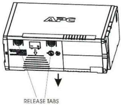
① Press release tabs and slide off battery door.
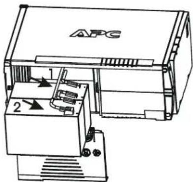
② Disconnect the battery wires.

③ Replace with the new battery and the connect the wires.
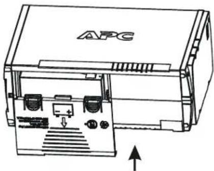
4 Close the battery door.
natural_image
Technical line drawing of an APC device showing internal components and a directional arrow (no text or symbols beyond logo)Back-UPS BK 200/500, Back-UPS Pro, Smart-UPS SU 280/420
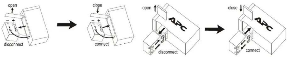
flowchart
graph LR
    A["open"] --> B["disconnect"]
    B --> C["close"]
    C --> D["connect"]
    D --> E["open"]
    E --> F["ABC"]
    F --> G["connect"]
    G --> H["close"]
    H --> I["ABC"]
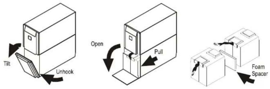
Back-UPS Pro USB 350/500/650 Back-UPS 1000/1400
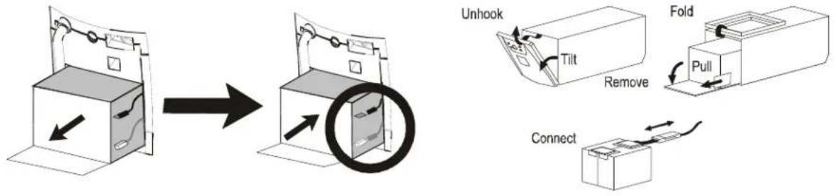
flowchart
graph TD
    A["Unhook"] --> B["Add Box"]
    B --> C["Remove Box"]
    C --> D["Unhook"]
    D --> E["Fold"]
    E --> F["Pull"]
    F --> G["Connect"]
Back-UPS Office 250/500

Back-UPS ES350/ES500
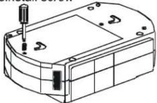
remove screw
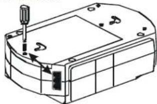
natural_image
Technical line drawing of a mechanical component with a screwdriver inserted (no text or symbols)slide cover off
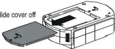
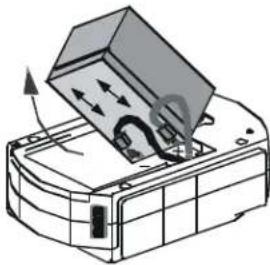
disconnect wires, replace with new battery and reconnect wires.
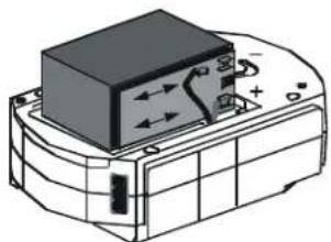
natural_image
Technical line drawing of a mechanical component with no visible text or symbolsBack-UPS ES 500
natural_image
Diagram of a device with a box and directional arrows indicating motion or movement (no text or symbols)Close cover and reinstall screw
natural_image
Technical line drawing of a mechanical housing or enclosure with mounting holes and internal components (no text or symbols)Back-UPS ES 350/450/550/650/725/750 (120 V)
Back-UPS ES 400/550/700 (230 V)
press release tabs and slide off cover
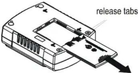
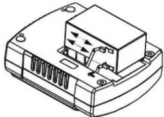
Disconnect wires, replace with new battery and reconnect wires.
natural_image
Technical line drawing of a mechanical component with internal components and directional arrows (no text or symbols)close cover
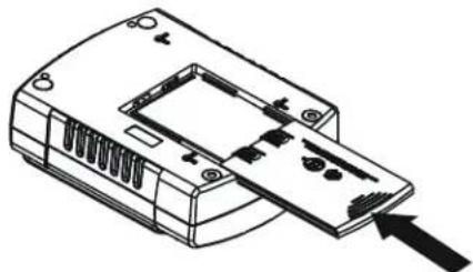
natural_image
Line drawing of a device casing with internal components and an arrow pointing to one end (no text or symbols)Smart-UPS
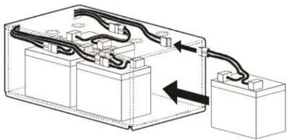
Smart-UPS Rack-Mount (5.25 inch models)
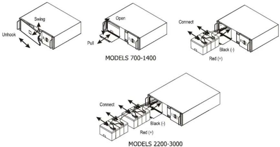
Smart-UPS Rack-Mount (8.75 inch models)
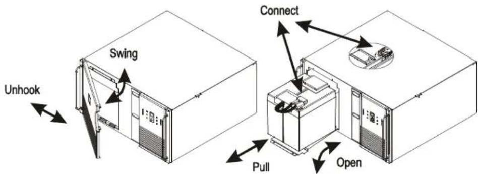
Smart-UPS Rack-Mount XL Battery Packs
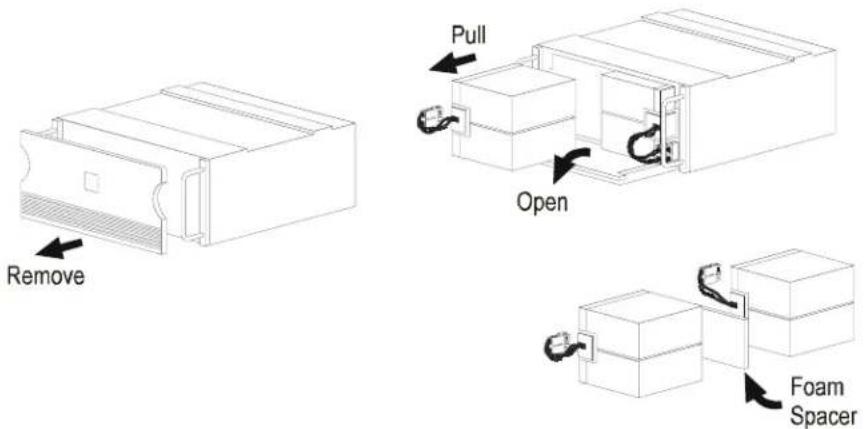
Smart-UPS 2200/3000
UXBP 24/48/48M SmartCell XR
natural_image
Diagram of an electrical enclosure with wiring and components, showing connections without any text or symbols.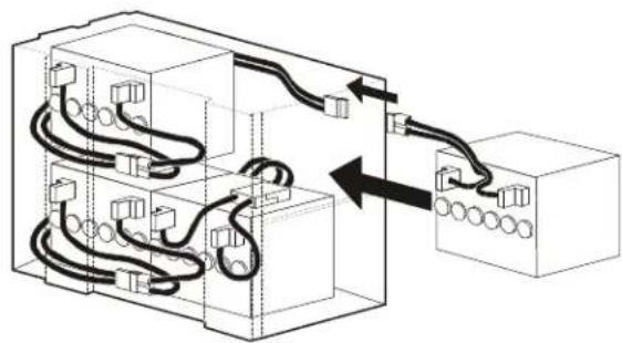
natural_image
Pure electrical circuit lines without any symbolsSmart-UPS 450/1500
Smart-UPS XLBP
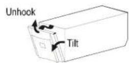
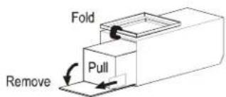
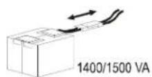
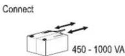
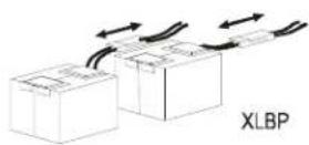
BX800/1100xx-xx
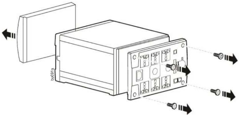
- To remove the front panel, insert a screwdriver into the notch on the bottom of the unit. Forcefully tap the screw driver to unsnap the front panel off of the unit. Remove the screws from the back panel of the unit.
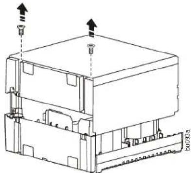
- Remove the side panels.
natural_image
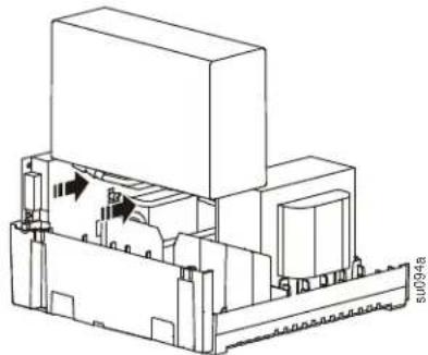
Technical line drawing of a mechanical assembly with mounting holes and arrows indicating force or movement (no text or symbols)- Detach the red and black wires from the battery. Remove the old battery and replace with new battery. Reconnect the battery wires, red to the + and black to the -. Reassemble the unit.
natural_image
Technical line drawing of an electronic component with internal structure and mounting holes (no text or symbols)BX650xx-xx
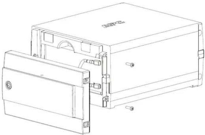
- Remove screws from bottom of the front panel of the UPS. Slide the front panel upwards to remove it.
natural_image
Technical line drawing of a mechanical device housing with mounting bracket and internal components (no text or symbols)- Detach the red and black wires from the battery.
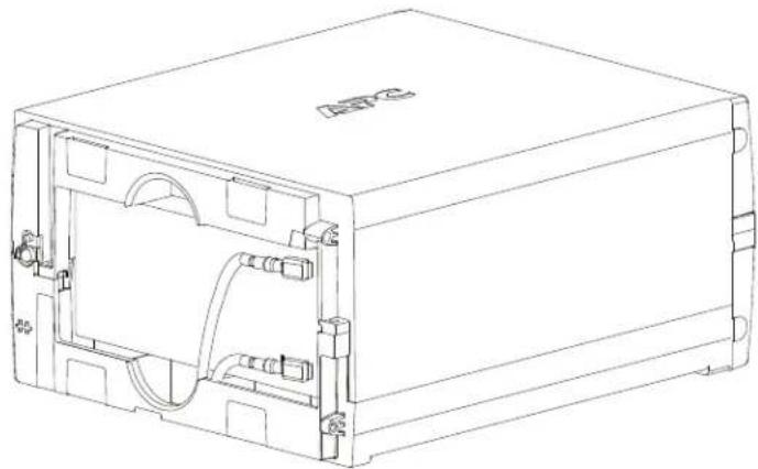
natural_image
Technical line drawing of an electronic device casing with internal components and wiring (no text or symbols)- Replace with a new battery. Connect the wires: red to the "+" terminal and black to the "-" terminal. Reassemble the UPS.
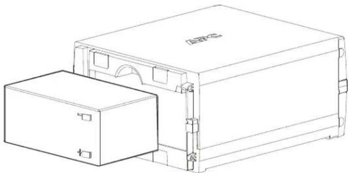
natural_image
Technical line drawing of a mechanical device with two boxes and mounting brackets (no text or symbols)© 2012 APC by Schneider Electric. APC, the APC logo, Back-UPS, and Smart-UPS are owned by Schneider Electric Industries S.A.S., American Power Conversion Corporation, or their affiliated companies. All other trademarks are property of their respective owners.
Brand : APC
Model : APCRBC142
Category : Battery