
ENRXWI-G - Wi-Fi repeater ENCORE - Free user manual and instructions
Find the device manual for free ENRXWI-G ENCORE in PDF.


| Product Type | Wi-Fi Repeater / Wireless Access Point |
| Model | ENRXWI-G |
| Brand | ENCORE |
| Wireless Standards | IEEE 802.11b/g |
| Data Transfer Rate | Up to 54 Mbps (with automatic scale back) |
| Frequency Band | 2.4 GHz (2412-2472 MHz depending on region) |
| Security | 64/128-bit WEP, WPA, WPA2, WPA-PSK, WPA2-PSK |
| Interfaces | 1 x 10/100 Mbps RJ45 LAN port |
| Antenna | 1 x 2 dBi detachable dipole antenna |
| Operating Modes | Access Point, AP Client, WDS, AP+WDS, Repeater |
| LED Indicators | Power (green), LAN (Link/Activity), WLAN (Activity) |
| Power Supply | DC 7.5V, 1A |
| Power Consumption | 4.2W max |
| Dimensions (W x H x D) | 140 x 98 x 30 mm (without antenna) |
| Weight | Approximately 200 g |
| Operating Temperature | 0 to 40 °C |
| Storage Temperature | -10 to 70 °C |
| Humidity (Operating) | 10% to 90% |
| Humidity (Storage) | 5% to 90% |
| Certifications | FCC Class B, CE Mark |
| Configuration | Web-based GUI via browser |
| Reset | Press reset button >5 seconds for factory defaults |
| Maintenance | Keep in well-ventilated area; avoid moisture and extreme temperatures |
| Safety | RF exposure: maintain at least 20 cm distance from body |
Frequently Asked Questions - ENRXWI-G ENCORE
User questions about ENRXWI-G ENCORE
0 question about this device. Answer the ones you know or ask your own.
Ask a new question about this device
Download the instructions for your Wi-Fi repeater in PDF format for free! Find your manual ENRXWI-G - ENCORE and take your electronic device back in hand. On this page are published all the documents necessary for the use of your device. ENRXWI-G by ENCORE.
USER MANUAL ENRXWI-G ENCORE
802.11g Wireless LAN
Access Point
User Guide
Regulatory notes and statements
Wireless LAN, Health and Authorization for use
Radio frequency electromagnetic energy is emitted from Wireless LAN devices. The energy levels of these emissions however are far much less than the electromagnetic energy emissions from wireless devices like for example mobile phones. Wireless LAN devices are safe for use frequency safety standards and recommendations. The use of Wireless LAN devices may be restricted in some situations or environments for example:
- On board of airplanes, or
·In an explosive environment, or
·In case the interference risk to other devices or services is perceived or identified as harmful
In case the policy regarding the use of Wireless LAN devices in specific organizations or environments (e.g. airports, hospitals, chemical/oil/gas industrial plants, private buildings etc.) is not clear, please ask for authorization to use these devices prior to operating the equipment.
Regulatory Information/disclaimers
Installation and use of this Wireless LAN device must be in strict accordance with the instructions included in the user documentation provided with the product. Any changes or modifications made to this device that are not expressly approved by the manufacturer may void the user's authority to operate the equipment. The Manufacturer is not responsible for any radio or television interference caused by unauthorized modification of this device, of the substitution or attachment. Manufacturer and its authorized resellers or distributors will assume no liability for any damage or violation of government regulations arising from failing to comply with these guidelines.
USA-FCC (Federal Communications Commission) statement
This device complies with Part 15 of FCC Rules.
Operation is subject to the following two conditions:
-
This device may not cause interference, and
-
This device must accept any interference, including interference that may cause undesired operation of this device.
FCC Radio Frequency Exposure statement
This Wireless LAN radio device has been evaluated under FCC Bulletin OET 65 and found compliant to the requirements as set forth in CFR 47 Sections 2.1091, 2.1093, and 15.247 (b) (4) addressing RF Exposure from radio frequency devices. The radiated output power of this Wireless LAN device is far below the FCC radio frequency exposure limits. Nevertheless, this device shall be used in such a manner that the potential for human contact during normal operation is minimized.
When nearby persons has to be kept to ensure RF exposure compliance, in order to comply with RF exposure limits established in the ANSI C95.1 standards, the distance between the antennas and the user should not be less than 20 cm.
FCC Interference Statement
This equipment has been tested and found to comply with the limits for a Class B digital device, pursuant to Part 15 of the FCC Rules. These limits are designed to provide reasonable protection against harmful interference in a residential installation.
This equipment generates, uses, and can radiate radio frequency energy. If not installed and used in accordance with the instructions, it may cause harmful interference to radio communications.
However, there is no guarantee that interference will not occur in a particular installation. If this equipment does cause harmful interference to radio or television reception, which can be determined by turning the equipment off and on, the user is encouraged to try and correct the interference by one or more of the following measures:
- Reorient or relocate the receiving antenna.
- Increase the distance between the equipment and the receiver.
- Connect the equipment to an outlet on a circuit different from that to which the receiver is connected.
- Consult the dealer or an experienced radio/TV technician for help.
Export restrictions
This product or software contains encryption code that may not be exported or transferred from the US of Canada without an approved US Department of Commerce export license.
Safety Information
Your device contains a low power transmitter. When device is transmitted it sends out radio frequency (RF) signal.
CAUTION: To maintain compliance with FCC's RF exposure guidelines, this equipment should be installed and operated with minimum distance 20cm between the radiator and your body. Use on the supplied antenna. Unauthorized antenna, modification, or attachments could damage the transmitter and may violate FCC regulations.
The antenna(s) used for this transmitter must be installed to provide a separation distance of at least 20 cm from all persons and must not be co-located or operating in conjunction with any other antenna or transmitter.
CE Mark Warning
This is a Class B product. In a domestic environment, this product may cause radio interference, in which case the user may be required to take adequate measures.
Protection requirements for health and safety – Article 3.1a
Testing for electric safety according to EN 60950 has been conducted. These are considered relevant and sufficient.
Protection requirements for electromagnetic compatibility – Article 3.1b
Testing for electromagnetic compatibility according to EN 301 489-1, EN 301 489-17 and EN 55024 has been conducted. These are considered relevant and sufficient.
Effective use of the radio spectrum - Article 3.2
Testing for radio test suites according to EN 300 328-2 has been conducted. These are considered relevant and sufficient.
CE in which Countries where the product may be used freely:
Germany, UK, Italy, Spain, Belgium, Netherlands, Portugal, Greece, Ireland, Denmark, Luxembourg, Austria, Finland, Sweden, Norway and Iceland.
France: The use of other channels that the channel 10 through 13 is prohibited by law.

TABLE OF CONTENT
About This Guide .... 1
Purpose....1
Overview of this User's Guide .... 1
Unpacking and Setup....2
Unpacking....2
Setup 2
Hardware Installation....3
Front panel....3
Rear Panel....3
Hardware connections 4
Connect to the Switch/Hub 4
Check the installation....4
Configuring the Wireless LAN Access Point....5
Login to the Wireless AP through WLAN 5
Login....5
Main Screen of the Access Point....6
Wizard....7
Status....9
Basic Setting....11
Access Point Mode 11
AP Client mode....14
WDS mode....16
AP+WDS mode 20
Repeater mode 21
IP Setting 24
Advanced Setting....25
Security 26
Tools 27
Technical Specifications....28
Congratulations on your purchase of this IEEE 802.11g Wireless LAN Access Point. This manual helps to features the innovating wireless technology that can help you build a wireless network easily! This manual contains detailed instructions in operation of this product. Please keep this manual for future reference.
With a WLAN (IEEE 802.11g) Access Point, a mobile computer can share data with another mobile computer in a wireless way. Easy-to-use utilities are bundled with WLAN Access Point for configuration and monitoring purposes.
WLAN networking can wirelessly transmit and receive data, minimizing the need for wired connections, at a speed of up to Fifty-four megabit per second. With WLAN networking, you can locate your PC wherever you want without wires and cables.
WLAN networking provides users with an access to real-time information anywhere in their organization. The mobility provides productivity and service, which are not available under wired networks.
Purpose
This manual discusses how to install the WLAN Access Point.
Overview of this User's Guide
Introduction. Describes the WLAN Access Point and its features.
Unpacking and Setup. Helps you get started with the basic installation of the WLAN Access Point.
Hardware Installation. Describes the LED indicators of the AP.
Software Installation. Tells how to setup the driver and the utility setting.
Technical Specifications. Lists the technical (general, physical and environmental) specifications of the WLAN Access Point.
This chapter provides unpacking and setup information for the Access Point.
Unpacking
Open the box of the Access Point and carefully unpack it. The box should contain the following items:
◆ One Wireless Access Point
◆ One external power adapter
◆ One CD-Rom (User's guide)
If any item is found missing or damaged, please contact your local reseller for replacement.
Setup
The setup of the Wireless Access Point can be performed using the following steps:
◆ Locate an optimum location for the Wireless LAN Access Point (AP). The best place for your AP is usually the center of your wireless network, with line of sight to all of your mobile stations.
- Visually inspect the Ethernet RJ45 port connector and make sure that it is fully plugged in to the system’s Ethernet switch/hub port.
◆ Fix the direction of the antennas. Try to place the AP in a position that can best cover your wireless network. Normally, the higher you place the antenna, the better the performance will be. The antenna’s position enhances the receiving sensitivity.
◆ Visually inspect if the Power Adapter was fully plugged to the device power jack.
Front panel
The figure below shows the LED Indicator of the Wireless LAN Access Point.

Power:
This indicator lights green when the Access Point receives power. Otherwise, it turns off.
WLAN:
The indicator blinking green whiles the wireless LAN activity.
LAN (Link/ACT):
The indicator lights green when the LAN port is connected to a Ethernet network successful. Otherwise, the indicator blinking green while transmitting or receiving data on the Ethernet network.
Rear Panel
The figure below shows the rear panel of the Access Point

LAN
Ethernet port with 10/100Mbps Fast Ethernet connections, connect this port to switch/hub.
RESET
The Reset function is to reset the setting back to factory default setting, once you press the “RESET” button more than 5 seconds.
Power
Connect the Power Adapter DC plug to the AP's power jack.
Antenna
One external dipole antenna.
Hardware connections

flowchart
graph TD
    A["Switch / Hub"] --> B["AP Router"]
    B --> C["Notebook"]
    B --> D["Notebook"]
    B --> E["PC"]
    B --> F["Computer"]
    B --> G["Computer"]
    style A fill:#f9f,stroke:#333
    style B fill:#ccf,stroke:#333
    style C fill:#cfc,stroke:#333
    style D fill:#fcc,stroke:#333
    style E fill:#cff,stroke:#333
    style F fill:#ffc,stroke:#333
    style G fill:#fcc,stroke:#333
Connect to the Switch/Hub
-
Plug in one end of the RJ45 network cable to the Switch/Hub port,
-
Plug in the other end of the RJ45 network cable to the Wireless Access Point.
Check the installation
The LEDs of the Access Point are clearly visible and the status of the network link can be seen instantly:
-
With the power source on, once the device is connected, the Power, LAN and WLAN port LEDs will light up indicating a normal status.
-
If the LAN Port's Link indicator does not light up then check the RJ-45 cable if it is firmly feed to the RJ45 port, while the LAN is link up to the Switch/Hub, the LAN port's LED will light up.
The Wireless Access Point has a Web GUI interface for the configuration. The AP can be configured through the Web Browser. A network manager can manage, control and monitor the AP from the local LAN. This section indicates how to configure the AP to enable its functions.
Login to the Wireless AP through WLAN
Before configuring the Wireless AP through WLAN, make sure that the SSID, Channel and the WEP was set properly.
The default setting of the Wireless AP that you will use:
◆ SSID: default
◆ Channel: 6
◆ WEP Encryption: disable
◆ IP address: 192.168.1.1
Login
Before you configure this device, note that when the AP is configured through an Ethernet connection, make sure the manager PC must be set on same the IP network. For example, when the default network address of the default IP address of the AP is 192.168.1.1, then the manager PC should be set at 192.168.1.x (where x is a number between 2 and 254), and the default subnet mask is 255.255.255.0.
Open Internet Explorer 5.0 or above Web browser.
Enter IP address http://192.168.1.1 (the factory-default IP address setting) to the address location.

When there is a screen needs to enter the User name and Password, both of the default Username and Password is “admin”

Main Screen of the Access Point
The screen will show the status of the AP when you login to the AP.
There are seven main functions included in the top side of the main screen: Wizard, Status, Basic Setting, IP Setting, Advanced Setting, Security and Tools. Point the selections in the top side of the menu screen.

Wizard
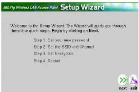
Setup wizard is provided as the part of the web configuration utility. User can simply follow the step-by-step process to get Access Point configuration ready to run in 4 easy steps by clicking on the “Wizard” button on the function menu. The following screen will appear. Please click “Next” to continue.
Step 1: Set Password
User can change the password and then click "Next" to continue.

Step2: Set WLAN Connection
Please type the name of SSID and select the Channel. Then, click “Next” to continue.

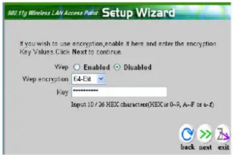
Step 3: Set WEP Encryption
If user wants to enable WEP, please click “Enabled”. Then, select the key size of WEP encryption and enter the key value in the key text box. Please click “Next” to continue.
Step 4: Restart
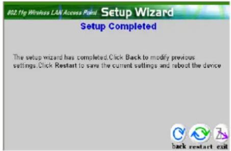
The Setup wizard is now completed. The new settings will be effective after the Access Point restarted. Please click “Restart” to reboot the Access Point. If user does not want to make any changes, please click “exit” to quit without any changes. User also can go back to modify the setting by clicking “back”.
Status
This page as below shows the following information.

Firmware Version: Shows the current firmware version and released date code.
LAN: Shows the Mac address, IP address (default: 192.168.1.1), Subnet Mask, Gateway Address. The current LAN traffic calculated in terms of number of packets sent and received by AP through wired connection is also displayed.
Wireless: Shows the Mac address, current SSID, the status of Encryption Function (Enable or Disable), the current using channel. The current wireless traffic calculated in terms of number of packets sent and received by AP through wireless communication is also displayed.
View Log: Once clicked, the page will change to login page. The login page records every event and the time that it happens.
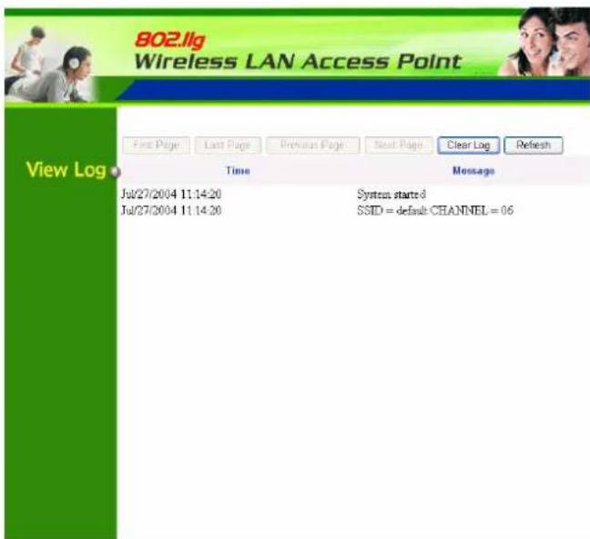
User may clear the entries recorded in the log by clicking the “Clear Log” button, and refresh the screen to show the latest log entries by clicking the “Refresh” button.
Basic Setting
This is the page allow user to change the access point settings.

AP Name: The name of the AP, which can be used to identify the Access Point among the all the Access Points in the wireless network.
Mode: The WLAN AP supports five operation mode for Access Point, AP Client, WDS (Wireless Distribution System), AP+WDS and Repeater mode.
Access Point Mode
Configure the AP to Access Point mode; with this mode, WLAN clients can access LAN or other WLAN clients through this AP.

flowchart
graph TD
    A["Internet"] --> B["ADSL/Cable Modem"]
    B --> C["Access Point"]
    C --> D["Notebook"]
    C --> E["PC"]
    C --> F["Notebook"]
    C --> G["Notebook"]
AP mode application
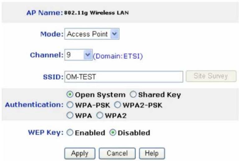
AP mode configuration
Channel: The channel that AP will operate in. User can select the channel range from 1 to 11 for North America (FCC) domain, 1 to 13 for European (ETSI) domain and 1 to 14 for Japanese domain.
SSID: Service Set Identifier, which is a unique name shared among all clients and nodes in a wireless network. The SSID must be identical for each clients and nodes in the wireless network.
Authentication Type: The authentication type default is set to Open system. There are six options: Open system; Shared Key; WPA-PSK, WPA2-PSK, WPA and WPA2. User may want to set to Shared Key when the clients and AP in the same wireless network enable the encryption. All the nodes and hosts on the network must use the same authentication type.
WEP Key: To disable WEP security, click on the “Disable” option. To enable WEP security, there are 2 types to select – 64bits and 128 bits. When it is selected, the key value must be entered in ASCII or HEX format.
Note: When the WEP security is enabled, all the wireless clients that wish to connect to the Access Point must also have WEP enabled with the identical WEP Key value entered.
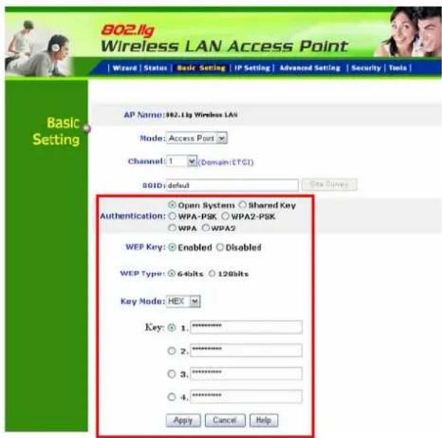
WPA-PSK / WPA2-PSK:
If WPA-PSK or WPA2-PSK is selected, user needs to set the key in the passphrase field as the below screen. The key length should be 8 characters at least.

WPA / WPA2:
If WPA or WPA2 is selected, the below screen is shown. Please set the length of the encryption key and the parameters for the RADIUS server.

RADIUS Server 1:
Enter the IP address of and the Port used by the Primary Radius Server, enter the Shared Secret, which is used by the Radius Server.
RADIUS Server 2: (optional)
Enter the IP address of and the Port used by the Secondary Radius Server, enter the Shared Secret, which is used by the Radius Server.
Apply: For the changes made to any of the items above to be effective, click "Apply". The new settings are now been saved to Access Point and will be effective once the Access Point restarts.
AP Client mode
Configure the AP to AP Client mode; the AP will be a wireless Ethernet adapter transforms any Ethernet-enabled devices to have the wireless function.
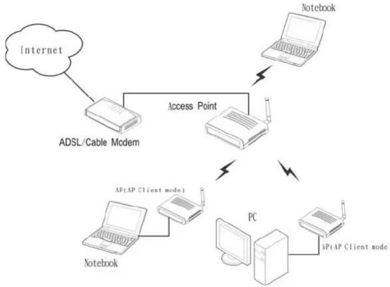
flowchart
graph TD
    A["Internet"] --> B["ADSL/Cable Modem"]
    B --> C["Access Point"]
    C --> D["PC"]
    D --> E["AP(AP Client node)"]
    E --> F["Notebook"]
    C --> G["Notebook"]
    style A fill:#f9f,stroke:#333
    style D fill:#ccf,stroke:#333
    style E fill:#cfc,stroke:#333
    style F fill:#fcc,stroke:#333
    style G fill:#cff,stroke:#333
AP Client mode application

AP Client mode configuration
SSID: Service Set Identifier, which is a unique name shared among all clients and nodes in a wireless network. The SSID must be identical for each clients and nodes in the wireless network.
Site Survey: This button allows user to enable the Site Survey function to scan for the available wireless network (wireless clients and Access Points) and establish wireless communications with one. Selected one of them in list to establish communications and click “Connect” button.
| SSID | BSSID | Channel | Type | Encrypt | Signal | Select |
| PM11G | 00:03:2F2d9a:9b | 9(B+G) | AP | yes | 76 | ○ |
| WBR2310 | 00:13:46 aa:ac:40 | 6(B+G) | AP | yes | 60 | ○ |
| Weiwel | 00:0d:0b ae:09:35 | 2(B+G) | AP | yes | 56 | ○ |
| Ethan_524 | 00:0d:88 eb:99:5c | 9(B+G) | AP | yes | 55 | ○ |
| aa1111111111000000000011111111111 | 00:13:46 a2:54:18 | 5(B+G) | AP | yes | 46 | ○ |
| God bless you | 00:03:2F1E32:29 | 6(B+G) | AP | yes | 35 | ○ |
| IntelAP | 00:02:b3:92:67:bc | 3(B) | AP | no | 27 | ○ |
| DI-624-TEST | 00:10:ab cdcc:03 | 6(B+G) | AP | yes | 18 | ○ |
| IBM | 02:20:e1 2a4c:7c | 11(B) | Ad hoc | no | 18 | ○ |
Authentication Type: The authentication type default is set to Open system. There are four options: Open system; Shared Key; WPA-PSK and WPA2-PSK. User may want to set to Shared Key when the clients and AP in the same wireless network enable the WEP encryption. All the nodes and hosts on the network must use the same authentication type.
WEP Key: To disable WEP security, click on the “Disable” option. To enable WEP security, there are 2 types to select – 64bits and 128 bits. When it is selected, the key value must be entered in ASCII or HEX format.
Note: When WEP security is enabled, all the wireless clients that wish to connect to the Access Point must also have WEP enabled with the identical WEP Key value entered.

WPA-PSK / WPA2-PSK:
If WPA-PSK or WPA2-PSK is selected, user needs to set the key in the passphrase field as the below screen. The key length should be 8 characters at least.

Apply: For the changes made to any of the items above to be effective, click "Apply". The new settings are now been saved to Access Point and will be effective once the Access Point restarts.
Note: For entering to the Web Setting page after changing to AP Client mode, change your PC/Notebook IP address to 192.168.1.x. After changing your IP address, type 192.168.1.1 on the Web browser to enter the setting of this Wireless AP.
WDS mode
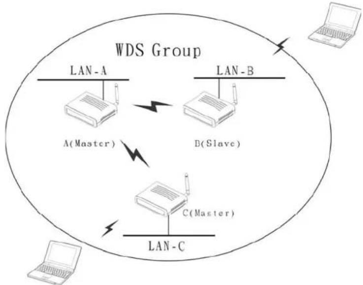
With WDS (Wireless Distribution System) mode, user can use wireless media to communicate two or more LANs through the AP with WDS mode, all of the LAN will be combined in the WDS group, for example:
Single WDS group application:
When there are three APs joined to the WDS group, one of the AP in WDS mode will be the Master, the other two APs will be the Slave, all of the APs in the WDS group must use the same wireless channel and the same security setting, the Master need to fill all the Slave's MAC address in the “Remote AP Mac” list, and the Slave need to fill the Master's MAC address in the “Remote AP Mac” list, the maximum of one Master can join eight Slave to be one WDS group.
In this example, LAN-A can communicate with LAN-B and LAN-C, and LAN-B can communicate with LAN-C through the AP-A. All of LANs will be at the same LAN environment coming through LAN-A.

flowchart
graph TD
    A["LAN-A"] -->|A(Master)| B["LAN-B"]
    B -->|B(Slave)| C["LAN-C"]
    C -->|C(Slave)| D["WDS Group"]
    style A fill:#f9f,stroke:#333
    style B fill:#f9f,stroke:#333
    style C fill:#f9f,stroke:#333
    style D fill:#f9f,stroke:#333
WDS mode application (Single WDS group)

WDS mode configuration for Example-1
Multiple WDS group application:
When there are five APs to be join into two separated WDS group, the member of WDS group 1 is AP-A, AP-B and AP-C, and member of the WDS group 2 is AP-C, AP-D and AP-E, the AP-C will join both of WDS group 1 and WDS group 2, each WDS Group 1 will be one master and the other will be slave.
The AP-A and AP-C will be both as a Master AP for both WDS Groups, the AP-A represent for the master of WDS Group 1, the AP-C represent for the master of the WDS Group 2 and at the same time AP-C will be the slave of WDS Group 1, so all of the APs in the two WDS groups must use the same wireless channel and same security, the Master need to fill all of Slave's MAC address in the “Remote AP Mac” list, and the Slave need to fill the Master's MAC address in the “Remote AP Mac” list, maximum allow one Master can be join eight Slaves to be one WDS group.
In this example, LAN-A can communicate with LAN-B and LAN-C, and LAN-B can communicate with LAN-C through the AP-A. LAN-B will have the same LAN environment coming through LAN-A.
LAN-E can communicate with LAN-B and LAN-D, LAN-E can communicate with LAN-D through AP-C, LAN-E can communicate with LAN-B through AP-C and AP-A, LAN-E will have the same LAN environment coming through LAN-A.
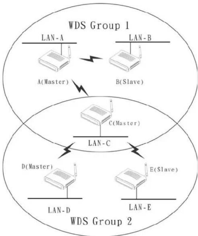
flowchart
graph TD
    subgraph WDS Group 1
        A["LAN-A"] -->|A(Master)| B["B(Slave)"]
        C["LAN-B"] -->|B(Slave)| B
        D["LAN-C"] -->|D(Master)| E["E(Slave)"]
        F["LAN-D"] -->|LAN-D| E
        G["LAN-E"] -->|LAN-E| E
    end
    subgraph WDS Group 2
        H["LAN-A"] --> I["A(Master)"]
        J["LAN-B"] --> K["B(Slave)"]
        L["LAN-C"] --> M["C(Master)"]
        N["LAN-D"] --> O["E(Slave)"]
        P["LAN-E"] --> Q["E(Slave)"]
    end
WDS mode application (Multiple WDS group)
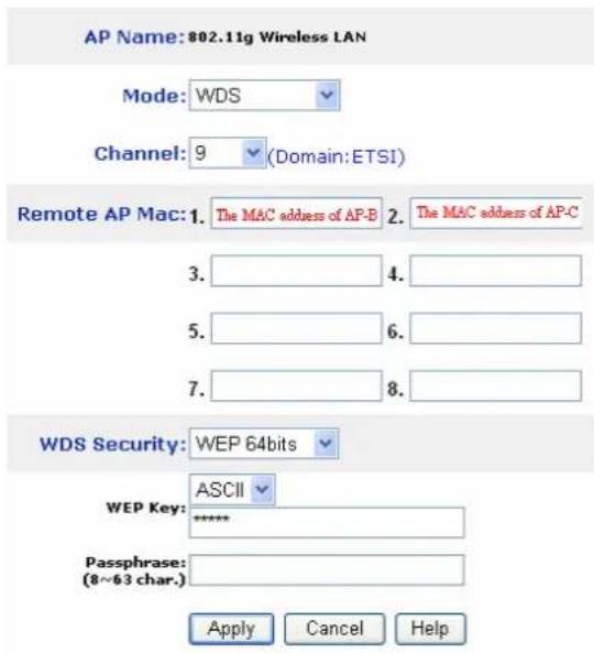
Master setting (AP-A, WDS Group 1)
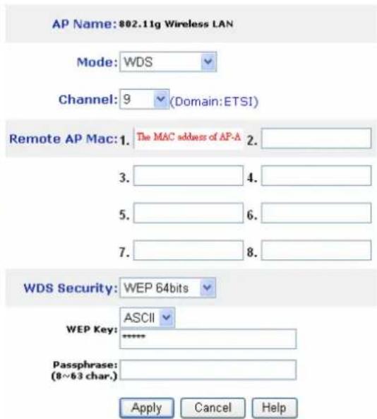
Slave setting (AP-B, WDS Group 1)
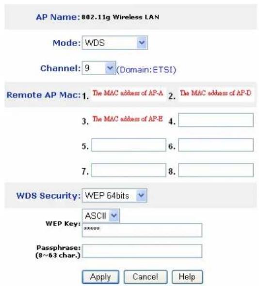
Master setting (AP-C, WDS Group 2)

Slave setting (AP-D and AP-E, WDS Group 2)
WDS mode configuration for Example-2
AP+WDS mode
With WDS+AP mode, user can use wireless media to communicate two or more LANs through the AP with WDS+AP mode, all of LAN will be combined in the WDS group and WLAN client can access to the AP with AP+WDS mode.
flowchart
graph TD
    A["LAN-A"] -->|Wireless Link| B["LAN-B"]
    B -->|Wireless Link| C["LAN-C"]
    C -->|Wireless Link| A
    D["A(Master)"] -->|Wireless Link| C
    E["B(Slave)"] -->|Wireless Link| C
    F["C(Master)"] -->|Wireless Link| C
    G["Laptop"] --> H["Network"]
    style A fill:#f9f,stroke:#333
    style B fill:#f9f,stroke:#333
    style C fill:#f9f,stroke:#333
    style D fill:#ccf,stroke:#333
    style E fill:#ccf,stroke:#333
    style F fill:#ccf,stroke:#333
    style G fill:#ccf,stroke:#333
WDS+AP mode application
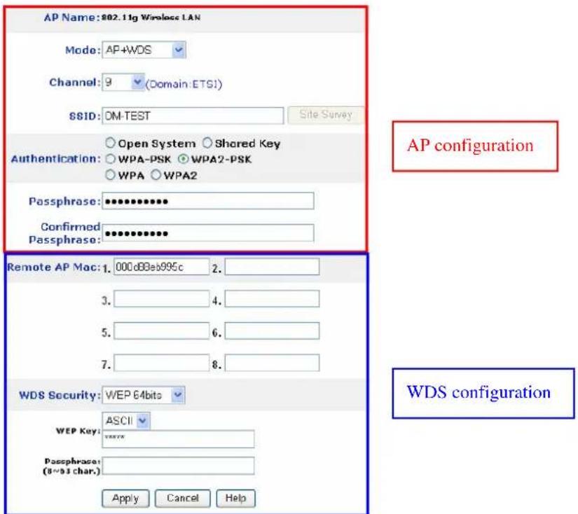
Please refer the AP mode and WDS mode for detail configuration.
Repeater mode
Configure the AP to Repeater mode; the AP will be a wireless LAN repeater that will be extended the WLAN coverage range.

flowchart
graph TD
    A["Interact"] --> B["ADSL/Cable Modem"]
    B --> C["Access Point"]
    C --> D["Access Point (Repeater Mode)"]
    D --> E["PC"]
    B --> F["Notebook"]
    C --> G["Notebook"]
    D --> H["Notebook"]
    style A fill:#f9f,stroke:#333
    style B fill:#ccf,stroke:#333
    style C fill:#cfc,stroke:#333
    style D fill:#fcc,stroke:#333
    style E fill:#cff,stroke:#333
    style F fill:#ffc,stroke:#333
    style G fill:#ffc,stroke:#333
    style H fill:#ffc,stroke:#333
Repeater mode application
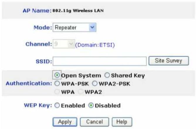
Repeater mode configuration
SSID: Service Set Identifier, which is a unique name shared among all clients and nodes in a wireless network. The SSID must be identical for each clients and nodes in the wireless network.
Site Survey: This button allows user to enable the Site Survey function to scan for the available wireless network (wireless clients and Access Points) and establish wireless communications with one. Selected one of them in list to establish communications and click “Connect” button.

Authentication Type: The authentication type default is set to Open system. There are four options: Open system; Shared Key; WPA-PSK and WPA2-PSK. User may want to set to Shared Key when the clients and AP in the same wireless network enable the WEP encryption. All the nodes and hosts on the network must use the same authentication type.
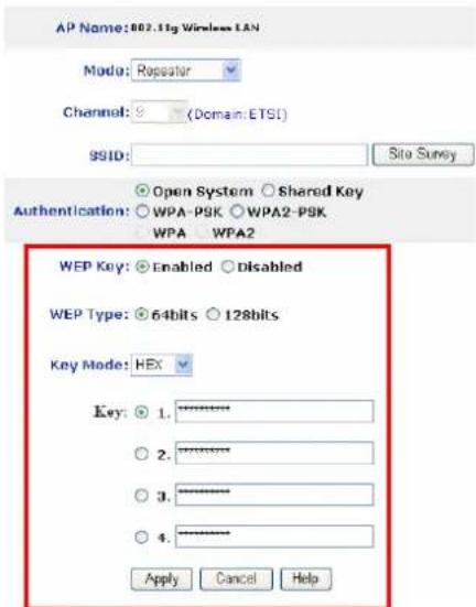
WEP Key: To disable WEP security, click on the “Disable” option. To enable WEP security, there are 2 types to select – 64bits and 128 bits. When it is selected, the key value must be entered in ASCII or HEX format.
Note: When WEP security is enabled, all the wireless clients that wish to connect to the Access Point must also have WEP enabled with the identical WEP Key value entered.
WPA-PSK / WPA2-PSK:
If WPA-PSK or WPA2-PSK is selected, user needs to set the key in the passphrase field as the below screen. The key length should be 8 characters at least.
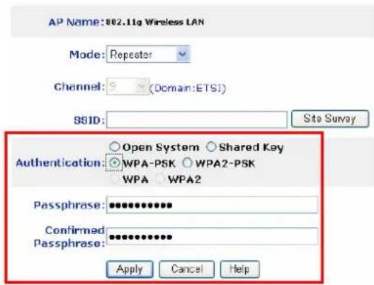
Apply: For the changes made to any of the items above to be effective, click “Apply”. The new settings are now been saved to Access Point and will be effective once the Access Point restarts.
IP Setting
This page allows user to configure the IP and DHCP settings of the Access Point.

The default IP address of this access point is 192.168.1.1 with the subnet mask of 255.255.255.0. User can type in other values for IP Address, Subnet Mask and Gateway and click “Apply” button for the changes to be effective.
User can also set the Access Point to obtain the IP from a DHCP server, but it is not recommended. Select the option “Obtain IP Automatically” and click “Apply” button for the changes to be effective.
DHCP Server: It is not recommended to enable the DHCP Server if user has a DHCP server running in LAN network because it probably will cause possible the conflict of IP assignment. Enable the DHCP server function by selecting the option “On”, and enter the IP range.
DNS Server: Type up to DNS IP address in the text boxes. Your ISP will provide you with this information.
Click "Apply" for the changes to be effective
Advanced Setting
This page contains configurations for advanced users, which the change reflects the wireless performance and operating modes.

Beacon Interval: To set the period of time in milliseconds that AP sends out a beacon. Default is 100 milliseconds.
RTS Threshold: To set the size of RTS/CTS packet size. Default is 2432 bytes.
Fragmentation Threshold: To set the number of bytes used for the fragmentation boundary for directed messages. Default is 2436 bytes.
DTIM Interval: This value indicates the interval of the Delivery Traffic Indication Message (DTIM). A DTIM field is a countdown field informing clients of the next window for listening to broadcast and multicast messages. When the access point has buffered broadcast or multicast messages for associated clients, it sends the next DTIM with a DTIM interval value. Access point clients hear the beacons and awaken to receive the broadcast and multicast messages.
SSID Broadcast: While SSID Broadcast is enabled, all wireless clients will be able to communicate with the access point. For secure purpose, user may want to disable SSID broadcast to allow only those wireless clients with the AP SSID to communicate with the access point.
Mode Setting: To setting the AP operation mode for 802.11g only or 802.11b/802.11g mix mode
TX Rates: Select one of the wireless communications transfer rates, measured in megabytes per second, based upon the speed of wireless adapters connected to the WLAN.
Security
This page is where user configures the security features supported by this Access Point.

Password: Allow user to change the new login password. Here are the necessary steps:
- Enter the new password in the "AP Password New:" field.
- Enter the new password again in the "Confirm" field.
- Click "Apply"
MAC Filter: MAC Filter function controls the MAC of the network devices that are listed in this table for access authorization or denial. There have three choices:
◆ Disable MAC Filters
◆ Only allow PCs with MAC listed below to access device
◆ Only deny PCs with MAC listed below to access device
The maximum number of MAC addresses that can be stored is 50. User can browse through the MAC address saved by selecting the MAC Filter List.
For any changes made in the security page, click “Apply” for the changes to be effective.
Tools
Four functions are provided in this page, Backup, Restore Settings, Restore default settings and Firmware Upgrade.

Save Settings to Local Hard Drive: Click on “Save Settings to Local Hard Drive” button, which will open a FileSave Dialog box, where user gets to save all the current settings and configurations to a file.
Restore Settings: Click on the “Browse” button to open a FileOpen Dialog box, where user gets to select the file, which saves previous settings and configurations. Upon selecting the saved file, click “Restore” and complete the restore process when the access point re-operates after it restarts.
Restore to default settings: Click on “Default” button to restore the access point back to its manufacture default settings.
Firmware Upgrade: Click on the “Browse” button to open a FileOpen Dialog box, where gets to select the firmware file, which download from the web for the latest version. Upon selecting the firmware file, click “Upgrade” and complete the firmware upgrade process when the Access Point re-operates after it restarts.
TECHNICAL SPECIFICATIONS
| General | |
| Standards | IEEE 802.11b/gIEEE 802.3u 10/100BASE-TX Fast Ethernet |
| Signal Type: DSSS (802.11b)OFDM (802.11g) | |
| Modulation: | QPSK / BPSK / CCK / OFDM |
| LED Indicators: Power, LAN (Link/Activity), WLAN (Link) | |
| Frequency 2412 MHz ~ 2462 MHz (FCC)2412 MHz ~ 2472 MHz (ETSI)2400 MHz ~ 2484 MHz (Japan) | |
| Channel 1 ~ 11 Channels (FCC)1 ~ 13 Channels (ETSI)1 ~ 14 Channels (Japan) | |
| Data Encryption: 64 bit / 128 bit WEP Encryption, WPA, WPA2, WPA-PSK,WPA2-PSK | |
| Data Transfer Rate Fast Ethernet: 10/100MbpsWireless: Up to 54Mbps (with Automatic Scale Back) | |
| Receiver Sensitivity 54Mbps: Typical -68 dBm @10% PER11Mbps: Typical -81 dBm @8% PER | |
| Transmit Power 802.11g: Minimum 13dBm typically802.11b: Minimum 15dBm typically | |
| Transmission Range: Outdoor: 100~300M (depends on environment)Indoor: 50~100M (depends on environment) | |
| Network Cables 2-pair UTP/STP Cat. 3,4,5 (100 m) | |
| Interface 1 x 10/100Mbps RJ45 port | |
| Antenna: 1 x 2 dBi Dipole Antenna | |
| Physical and Environmental | |
| DC inputs DC 7.5V /1A | |
| Power Consumption 4.2W (Max) | |
| Temperature Operating: 0 ~ 40 °C, Storage: -10 ~ 70 °C | |
| Humidity Operating: 10% ~ 90%, Storage: 5% ~ 90% | |
| Dimensions 140 x 98 x 30 mm (W x H x D) without Antenna | |
| EMI: FCC Class B, CE Mark B, | |

- 802.11g Wireless LAN
- Access Point
- User Guide
- Regulatory notes and statements
- Wireless LAN, Health and Authorization for use
- Regulatory Information/disclaimers
- USA-FCC (Federal Communications Commission) statement
- FCC Radio Frequency Exposure statement
- FCC Interference Statement
- Export restrictions
- Safety Information
- CE Mark Warning
- Protection requirements for health and safety – Article 3.1a
- Protection requirements for electromagnetic compatibility – Article 3.1b
- Effective use of the radio spectrum - Article 3.2
- CE in which Countries where the product may be used freely:
- TABLE OF CONTENT
- Purpose
- Overview of this User's Guide
- Unpacking
- Setup
- Front panel
- Power:
- WLAN:
- LAN (Link/ACT):
- Rear Panel
- LAN
- RESET
- Power
- Antenna
- Hardware connections
- Connect to the Switch/Hub
- Check the installation
- Login to the Wireless AP through WLAN
- Login
- Main Screen of the Access Point
- Wizard
- Step 1: Set Password
- Step2: Set WLAN Connection
- Step 3: Set WEP Encryption
- Step 4: Restart
- Status
- Basic Setting
- Access Point Mode
- WPA-PSK / WPA2-PSK:
- WPA / WPA2:
- RADIUS Server 1:
- RADIUS Server 2: (optional)
- AP Client mode
- WDS mode
- Single WDS group application:
- Multiple WDS group application:
- AP+WDS mode
- Repeater mode
- IP Setting
- Advanced Setting
- Security
- Tools
Brand : ENCORE
Model : ENRXWI-G
Category : Wi-Fi repeater