
AG-120 - Network card ZYXEL - Free user manual and instructions
Find the device manual for free AG-120 ZYXEL in PDF.


| Product Type | 802.11a/g Wireless USB Adapter |
| Brand | ZyXEL |
| Model | AG-120 |
| Wireless Standards | IEEE 802.11a/b/g |
| Frequency Bands | 2.4 GHz and 5 GHz |
| Maximum Data Rate | Up to 54 Mbps |
| Modulation Types | OFDM, CCK |
| Security | WEP 64/128/256-bit, WPA-PSK, WPA2-PSK, WPA, WPA2, IEEE 802.1x |
| Interface | USB 2.0 (backward compatible with USB 1.1) |
| Antenna | Internal |
| Operating Temperature | 0°C to 50°C |
| Operating Humidity | 10% to 90% (non-condensing) |
| Power Supply | Powered via USB bus (5V DC) |
| System Requirements | Windows 98/Me/2000/XP/Vista |
| Warranty | 2 years limited warranty |
| Operating Modes | Station (Infrastructure/Ad-Hoc) and Access Point (AP) mode |
| Wi-Fi Protected Setup (WPS) | Supported (Windows Vista only) |
| One-Touch Intelligent Security Technology (OTIST) | Supported |
Frequently Asked Questions - AG-120 ZYXEL
User questions about AG-120 ZYXEL
0 question about this device. Answer the ones you know or ask your own.
Ask a new question about this device
Download the instructions for your Network card in PDF format for free! Find your manual AG-120 - ZYXEL and take your electronic device back in hand. On this page are published all the documents necessary for the use of your device. AG-120 by ZYXEL.
USER MANUAL AG-120 ZYXEL
802.11a/g Wireless USB Adapter
User's Guide
Version 1.10
Edition 1
5/2008
ZyXEL
Copyright
Copyright © 2008 by ZyXEL Communications Corporation.
The contents of this publication may not be reproduced in any part or as a whole, transcribed, stored in a retrieval system, translated into any language, or transmitted in any form or by any means, electronic, mechanical, magnetic, optical, chemical, photocopying, manual, or otherwise, without the prior written permission of ZyXEL Communications Corporation.
Published by ZyXEL Communications Corporation. All rights reserved.
Disclaimer
ZyXEL does not assume any liability arising out of the application or use of any products, or software described herein. Neither does it convey any license under its patent rights nor the patent rights of others. ZyXEL further reserves the right to make changes in any products described herein without notice. This publication is subject to change without notice.
Trademarks
ZyNOS (ZyXEL Network Operating System) is a registered trademark of ZyXEL Communications, Inc. Other trademarks mentioned in this publication are used for identification purposes only and may be properties of their respective owners.
Certifications
Federal Communications Commission (FCC) Interference Statement
The device complies with Part 15 of FCC rules. Operation is subject to the following two conditions:
- This device may not cause harmful interference.
- This device must accept any interference received, including interference that may cause undesired operations.
This device has been tested and found to comply with the limits for a Class B digital device pursuant to Part 15 of the FCC Rules. These limits are designed to provide reasonable protection against harmful interference in a residential installation. This device generates, uses, and can radiate radio frequency energy, and if not installed and used in accordance with the instructions, may cause harmful interference to radio communications. However, there is no guarantee that interference will not occur in a particular installation.
If this device does cause harmful interference to radio/television reception, which can be determined by turning the device off and on, the user is encouraged to try to correct the interference by one or more of the following measures:
1 Reorient or relocate the receiving antenna.
2 Increase the separation between the equipment and the receiver.
3 Connect the equipment into an outlet on a circuit different from that to which the receiver is connected.
4 Consult the dealer or an experienced radio/TV technician for help.
FCC Radiation Exposure Statement
- This device has been tested to the FCC exposure requirements (Specific Absorption Rate).
- Testing was performed on laptop computers with antennas at 0mm spacing. The maximum SAR value is: 1.420W / kg at 2.4GHz and 0.518W / kg at 5GHz . The device must not be collocated with any other antennas or transmitters.
- This equipment has been SAR-evaluated for use in laptops (notebooks) with side slot configuration.
- The device complies with FCC RF radiation exposure limits set forth for an uncontrolled environment, under 47 CFR 2.1093 paragraph (d)(2). End users must follow the specific operating instructions for satisfying RF exposure compliance. To maintain compliance with FCC RF exposure compliance requirements, please follow operation instruction as documented in this manual.
- This transmitter must not be co-located or operating in conjunction with any other antenna or transmitter.
- For operation within 5.15 \~ 5.25GHz frequency range, it is restricted to indoor environment.
- IEEE 802.11b or 802.11g operation of this product in the U.S.A. is firmware-limited to channels 1 through 11.
注意!
体操 低功本舌沙辐射性舌模前埋随法
Changes or modifications not expressly approved by the party responsible for compliance could void the user's authority to operate the equipment.
This device has been designed for the WLAN 2.4 GHz and 5 GHz networks throughout the EC region and Switzerland, with restrictions in France.
This device has been designed for the WLAN 2.4 GHz network throughout the EC region and Switzerland, with restrictions in France.
This Class B digital apparatus complies with Canadian ICES-003.
Viewing Certifications
1 Go to http://www.zyxel.com.
2 Select your product from the drop-down list box on the ZyXEL home page to go to that product's page.
3 Select the certification you wish to view from this page.
Safety Warnings
For your safety, be sure to read and follow all warning notices and instructions.
- Do NOT use this product near water, for example, in a wet basement or near a swimming pool.
- Do NOT expose your device to dampness, dust or corrosive liquids.
- Do NOT store things on the device.
- Do NOT install, use, or service this device during a thunderstorm. There is a remote risk of electric shock from lightning.
- Connect ONLY suitable accessories to the device.
- ONLY qualified service personnel should service or disassemble this device.
- Do not use the device outside, and make sure all the connections are indoors. There is a remote risk of electric shock from lightning.
- Antenna Warning! This device meets ETSI and FCC certification requirements when using the included antenna(s). Only use the included antenna(s).
This product is recyclable. Dispose of it properly.
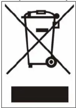
natural_image
Symbol of a trash bin crossed with no visible text or labelsZyXEL Limited Warranty
ZyXEL warrants to the original end user (purchaser) that this product is free from any defects in materials or workmanship for a period of up to two years from the date of purchase. During the warranty period, and upon proof of purchase, should the product have indications of failure due to faulty workmanship and/or materials, ZyXEL will, at its discretion, repair or replace the defective products or components without charge for either parts or labor, and to whatever extent it shall deem necessary to restore the product or components to proper operating condition. Any replacement will consist of a new or re-manufactured functionally equivalent product of equal or higher value, and will be solely at the discretion of ZyXEL. This warranty shall not apply if the product has been modified, misused, tampered with, damaged by an act of God, or subjected to abnormal working conditions.
Note
Repair or replacement, as provided under this warranty, is the exclusive remedy of the purchaser. This warranty is in lieu of all other warranties, express or implied, including any implied warranty of merchantability or fitness for a particular use or purpose. ZyXEL shall in no event be held liable for indirect or consequential damages of any kind to the purchaser.
To obtain the services of this warranty, contact your vendor. You may also refer to the warranty policy for the region in which you bought the device at http://www.zyxel.com/web/support_warranty_info.php.
Registration
Register your product online to receive e-mail notices of firmware upgrades and information at www.zyxel.com for global products, or at www.us.zyxel.com for North American products.
Customer Support
Please have the following information ready when you contact customer support.
- Product model and serial number.
- Warranty Information.
- Date that you received your device.
- Brief description of the problem and the steps you took to solve it.
| METHODLOCATION | SUPPORT E-MAIL TELEPHONE WEB SITE | REGULAR MAIL | ||
| SALES E-MAIL FAX FTP SITE | ||||
| CORPORATEHEADQUARTERS(WORLDWIDE) | support@zyxel.com.tw +886-3-578-3942 www.zyxel.com | www.europe.zyxel.com | ZyXEL Communications Corp.6 Innovation Road IIScience ParkHsinchu 300Taiwan | |
| sales@zyxel.com.tw +886-3-578-2439 ftp.zyxel.com | ftp.europe.zyxel.com | |||
| COSTA RICA | soporte@zyxel.co.cr | +506-2017878 | www.zyxel.co.cr | ZyXEL Costa RicaPlaza Roble EscazúEtapa El Patio, Tercer PisoSan José, Costa Rica |
| sales@zyxel.co.cr +506-2015098 ftp.zyxel.co.cr | ||||
| CZECH REPUBLIC | info@cz.zyxel.com | +420-241-091-350 | www.zyxel.cz | ZyXEL CommunicationsCzech s.r.o.Modranská 621143 01 Praha 4 - ModranyCeská Republika |
| info@cz.zyxel.com +420-241-091-359 | ||||
| DENMARK | support@zyxel.dk | +45-39-55-07-00 | www.zyxel.dk | ZyXEL Communications A/SColumbusvej2860 SoeborgDenmark |
| sales@zyxel.dk | +45-39-55-07-07 | |||
| FINLAND | support@zyxel.fi | +358-9-4780-8411 | www.zyxel.fi | ZyXEL Communications OyMalminkaari 1000700 HelsinkiFinland |
| sales@zyxel.fi | +358-9-4780 8448 | |||
| FRANCE | info@zyxel.fr | +33-4-72-52-97-97 | www.zyxel.fr | ZyXEL France1 rue des VergersBat. 1 / C69760 LimonestFrance |
| +33-4-72-52-19-20 | ||||
| GERMANY | support@zyxel.de | +49-2405-6909-0 | www.zyxel.de | ZyXEL Deutschland GmbH.Adenauerstr. 20/A2 D-52146WuerselenGermany |
| sales@zyxel.de | +49-2405-6909-99 | |||
| HUNGARY | support@zyxel.hu | +36-1-3361649 | www.zyxel.hu | ZyXEL Hungary48, Zoldlomb Str.H-1025, BudapestHungary |
| info@zyxel.hu | +36-1-3259100 | |||
| KAZAKHSTAN | http://zyxel.kz/support | +7-3272-590-698 | www.zyxel.kz | ZyXEL Kazakhstan43, Dostyk ave.,Office 414Dostyk Business Centre050010, AlmatyRepublic of Kazakhstan |
| sales@zyxel.kz | +7-3272-590-689 | |||
| NORTH AMERICA | support@zyxel.com | 1-800-255-4101+1-714-632-0882 | www.us.zyxel.com | ZyXEL Communications Inc.1130 N. Miller St.AnaheimCA 92806-2001U.S.A. |
| sales@zyxel.com | +1-714-632-0858 ftp.us.zyxel.com | |||
| METHODLOCATION | SUPPORT E-MAIL | TELEPHONE | WEB SITE | REGULAR MAIL |
| SALES E-MAIL | FAX | FTP SITE | ||
| NORWAY | support@zyxel.no | +47-22-80-61-80 | www.zyxel.no ZyXEL Communications A/S Nils Hansens vei 13 0667 Oslo Norway | |
| sales@zyxel.no | +47-22-80-61-81 | |||
| POLAND | info@pl.zyxel.com +48 | (22) 333 8250 www.pl.zyxel.com ZyXEL Communications ul. Okrzei 1A 03-715 Warszawa Poland | ||
| +48 (22) 333 8251 | ||||
| RUSSIA | http://zyxel.ru/support +7 | -095-542-89-29 www.zyxel.ru ZyXEL Russia | Ostrovityanova 37a Str. Moscow, 117279 Russia | |
| sales@zyxel.ru +7-095-542-89-25 | ||||
| SPAIN | support@zyxel.es | +34-902-195-420 | www.zyxel.es | ZyXEL Communications Arte, 21 5 ^a planta 28033 Madrid Spain |
| sales@zyxel.es | +34-913-005-345 | |||
| SWEDEN | support@zyxel.se | +46-31-744-7700 | www.zyxel.se ZyXEL Communications A/S Sjöporten 4, 41764 Göteborg Sweden | |
| sales@zyxel.se | +46-31-744-7701 | |||
| UKRAINE | support@ua.zyxel.com | +380-44-247-69-78 | www.ua.zyxel.com | ZyXEL Ukraine 13, Pimonenko Str. Kiev, 04050 Ukraine |
| sales@ua.zyxel.com | +380-44-494-49-32 | |||
| UNITED KINGDOM | support@zyxel.co.uk | +44-1344 303044 08707 555779 (UK only) | www.zyxel.co.uk | ZyXEL Communications UK Ltd.,11 The Courtyard, Eastern Road, Bracknell, Berkshire, RG12 2XB, United Kingdom (UK) |
| sales@zyxel.co.uk | +44-1344 303034 | ftp.zyxel.co.uk | ||
+” is the (prefix) number you enter to make an international telephone call.
Table of Contents
Copyright 3
Certifications 4
Safety Warnings 6
ZyXEL Limited Warranty....7
Customer Support......8
Table of Contents 11
List of Figures 15
List of Tables 19
Preface 21
Chapter 1 Getting Started ....23
1.1 About Your AG-220 23
1.1.1 Note for Windows Vista Users 23
1.2 Application Overview ......23
1.2.1 Station Mode ....23
1.2.1.1 Infrastructure ......24
1.2.1.2 Ad-Hoc 24
1.2.2 Access Point Mode 25
1.2.3 Changing AG-220 Mode 25
1.3 AG-220 Hardware and Utility Installation 26
1.3.1 ZyXEL Utility Icon ......26
1.4 Configuration Methods ......27
1.4.1 Enabling WZC 27
1.4.2 Accessing the ZyXEL Utility 27
Chapter 2 Tutorial ...... 29
2.1 Connecting to a Wireless LAN 29
2.2 Creating and Using a Profile ....31
2.3 Configuring the AG-220 as an AP ....34
Chapter 3
Wireless LAN Network.... 37
3.1 Wireless LAN Overview ......37
3.2 Wireless LAN Security 38
3.2.1 Hide SSID 38
3.2.2 MAC Address Filter .... 38
3.2.3 User Authentication and Encryption 39
3.2.3.1 WEP 39
3.2.3.2 IEEE 802.1x 40
3.2.3.3 WPA and WPA2 40
3.3 WiFi Protected Setup 41
3.3.1 Push Button Configuration ....41
3.3.2 PIN Configuration 42
3.3.3 How WPS Works ....43
3.3.3.1 Example WPS Network Setup 44
3.3.4 Limitations of WPS 46
3.4 Introduction to OTIST 47
3.4.1 Enabling OTIST 47
3.4.1.1 AP 47
3.4.1.2 Wireless Client ....48
3.4.2 Starting OTIST 48
3.4.3 Notes on OTIST 49
Chapter 4
Wireless Station Mode Configuration 51
4.1 Wireless Station Mode Overview 51
4.1.1 ZyXEL Utility Screen Summary 51
4.2 The Link Info Screen ....52
4.2.1 Trend Chart ....53
4.3 The Site Survey Screen ....54
4.3.1 Security Settings ....55
4.3.1.1 WEP Encryption ....55
4.3.1.2 WPA-PSK/WPA2-PSK 56
4.3.1.3 WPA/WPA2 57
4.3.1.4 IEEE 802.1x ....58
4.3.2 Confirm Save Screen 60
4.4 The Profile Screen ....60
4.4.1 Adding a New Profile 62
4.5 The Advanced Screen 66
4.6 The Adapter Screen ....67
4.7 The Adapter Screen (Windows Vista) 68
4.8 Security Settings in Windows Vista 69
4.8.1 Using PEAP in Vista 70
4.8.2 Using TLS in Vista 70
Chapter 5
Access Point Mode Configuration.... 73
5.1 Access Point Mode Introduction ......73
5.1.1 ZyXEL Utility Screen Summary 73
5.1.2 Additional Setup Requirements ....74
5.2 The Link Info Screen 74
5.3 The Configuration Screen ....75
5.4 The Advanced Screen ....77
5.5 The MAC Filter Screen ....78
Chapter 6
Maintenance 81
6.1 The About Screen 81
6.2 Uninstalling the ZyXEL Utility 81
6.2.1 Windows XP 81
6.2.2 Windows Vista 82
6.3 Upgrading the ZyXEL Utility 84
Chapter 7
Troubleshooting 85
7.1 Problems Starting the ZyXEL Utility 85
7.2 Problem Connecting to an Access Point 85
7.3 Problem with the Link Quality ....86
7.4 Problems Communicating With Other Computers 86
Appendix A
Product Specifications 87
Appendix B
Access Point Mode Setup Example 89
Appendix C
Windows Wireless Management.... 93
Appendix D
Wireless Security 115
Appendix E
Setting up Your Computer's IP Address.... 121
Index....135
List of Figures
Figure 1 Application: Infrastructure 24
Figure 2 Application: Ad-Hoc 25
Figure 3 Application: Access Point Mode 25
Figure 4 ZyXEL Utility: Change Modes 26
Figure 5 ZyXEL Utility: System Tray Icon 26
Figure 6 Enable WZC 27
Figure 7 Infrastructure Network ...... 29
Figure 8 ZyXEL Utility: Site Survey 30
Figure 9 ZyXEL Utility: Security Settings 30
Figure 10 ZyXEL Utility: Confirm Save 31
Figure 11 ZyXEL Utility: Link Info 31
Figure 12 ZyXEL Utility: Profile 32
Figure 13 ZyXEL Utility: Add New Profile 32
Figure 14 ZyXEL Utility: Profile Security 33
Figure 15 ZyXEL Utility: Profile Encryption 33
Figure 16 ZyXEL Utility: Profile Confirm Save 33
Figure 17 ZyXEL Utility: Profile Activate 34
Figure 18 ZyXEL Utility: AP: Link Info 35
Figure 19 ZyXEL Utility: AP: Configuration 35
Figure 20 Example of a Wireless Network ...... 37
Figure 21 Example WPS Process: PIN Method ...... 43
Figure 22 How WPS works .... 44
Figure 23 WPS: Example Network Step 1 45
Figure 24 WPS: Example Network Step 2 45
Figure 25 WPS: Example Network Step 3 46
Figure 26 ZyXEL Utility Menu Summary: Station Mode .... 51
Figure 27 Station Mode: Link Info 52
Figure 28 Station Mode: Link Info: Trend Chart 53
Figure 29 Station Mode: Site Survey 54
Figure 30 Station Mode: Security Setting: WEP 55
Figure 31 Station Mode: Security Setting: WPA-PSK/WPA2-PSK 56
Figure 32 Station Mode: Security Settings: WPA/WPA2 57
Figure 33 Station Mode: Security Setting: 802.1x 59
Figure 34 Confirm Save Screen 60
Figure 35 Station Mode: Profile 61
Figure 36 Station Mode: Profile: Add a New Profile 62
Figure 37 Station Mode: Profile: Select a Channel 63
Figure 38 Station Mode: Profile: Wireless Settings 64
Figure 39 Station Mode: Profile: Security Settings 65
Figure 40 Station Mode: Profile: Confirm New Settings 65
Figure 41 Station Mode: Profile: Activate the Profile 66
Figure 42 Station Mode: Advanced 66
Figure 43 Station Mode: Adapter 67
Figure 44 Station Mode: Adapter (Windows Vista) 68
Figure 45 Vista Security: Additional Information Required .... 70
Figure 46 Vista Security: Enter Credentials 70
Figure 47 Vista Security: Additional Information Required 71
Figure 48 Vista Security: Select Certificate 71
Figure 49 ZyXEL Utility Menu Summary: AP Mode 73
Figure 50 Access Point Mode: Link Info 74
Figure 51 Access Point Mode: Configuration 75
Figure 52 Access Point Mode: Advanced 78
Figure 53 Access Point Mode: MAC Filter 79
Figure 54 About 81
Figure 55 Uninstall: Confirm 82
Figure 56 Uninstall: Finish 82
Figure 57 Uninstall: Start 82
Figure 58 Uninstall: Control Panel 83
Figure 59 Uninstall: Control Panel 83
Figure 60 Uninstall: Control Panel 83
Figure 61 Uninstall: Remove Utility 83
Figure 62 Uninstall: Finish 84
Figure 63 Windows 2000: Start 89
Figure 64 Windows 2000: Network and Dial-up Connections 90
Figure 65 Windows 2000: Network Properties 90
Figure 66 W/ndows 2000: Network Properties: Select Network Adapter ....91
Figure 67 Windows 2000: Local Network 91
Figure 68 Vista: Start Menu 93
Figure 69 Vista: The Connect To Window 94
Figure 70 Vista: Additional Information 94
Figure 71 Vista: Enter Security Key 95
Figure 72 Vista: Connecting 95
Figure 73 Vista: Successful Connection ...... 96
Figure 74 Vista: Choose a Connection Option ...... 97
Figure 75 Vista: Connect Manually 97
Figure 76 Vista: Successfully Added Network 98
Figure 77 Vista: Set Up An Ad-hoc Network 99
Figure 78 Vista: Ad-hoc Options 99
Figure 79 Vista: Ad-hoc Network Ready 100
Figure 80 Windows XP SP1: Wireless Network Connection Status ..... 10
Figure 81 Windows XP SP2: Wireless Network Connection Status ..... 10
Figure 82 Windows XP SP1: Wireless Network Connection Properties ..... 102
Figure 83 Windows XP SP2: Wireless Network Connection Properties .... 102
Figure 84 Windows XP SP2: WZC Not Available 103
Figure 85 Windows XP SP2: System Tray Icon 103
Figure 86 Windows XP SP2: Wireless Network Connection Status .... 104
Figure 87 Windows XP SP1: Wireless Network Connection Status .... 104
Figure 88 Windows XP SP2: Wireless Network Connection .... 105
Figure 89 Windows XP SP1: Wireless Network Connection Properties ...... 106
Figure 90 Windows XP SP2: Wireless Network Connection: WEP or WPA-PSK .. 106
Figure 91 Windows XP SP2: Wireless Network Connection: No Security ..... 107
Figure 92 Windows XP: Wireless (network) properties: Association .... 107
Figure 93 Windows XP: Wireless (network) properties: Authentication .... 109
Figure 94 Windows XP: Protected EAP Properties 110
Figure 95 Windows XP: Smart Card or other Certificate Properties ...... 111
Figure 96 Windows XP SP2: Wireless Networks: Preferred Networks .... 112
Figure 97 Windows XP SP1: Wireless Networks: Preferred Networks .... 112
Figure 98 WPA-PSK Authentication 119
Figure 99 WPA(2) with RADIUS Application Example 120
Figure 100 Windows 98/Me: Network: Configuration 122
Figure 101 Windows 98/Me: TCP/IP Properties: IP Address 123
Figure 102 Windows 98/Me: TCP/IP Properties: DNS Configuration .... 124
Figure 103 Windows XP: Start Menu 125
Figure 104 Windows XP: Control Panel 125
Figure 105 Windows XP: Control Panel: Network Connections: Properties ..... 126
Figure 106 Windows XP: Local Area Connection Properties ...... 126
Figure 107 Windows XP: Advanced TCP/IP Settings 127
Figure 108 Windows XP: Internet Protocol (TCP/IP) Properties ...... 128
Figure 109 Windows Vista: Start Menu .... 129
Figure 110 Windows Vista: Control Panel 129
Figure 111 Windows Vista: Network And Internet 129
Figure 112 Windows Vista: Network and Sharing Center 129
Figure 113 Windows Vista: Network and Sharing Center 130
Figure 114 Windows Vista: Local Area Connection Properties .... 130
Figure 115 Windows Vista: Internet Protocol Version 4 (TCP/IPv4) Properties ..... 131
Figure 116 Windows Vista: Advanced TCP/IP Properties ...... 132
Figure 117 Windows Vista: Internet Protocol Version 4 (TCP/IPv4) Properties ..... 133
List of Tables
Table 1 ZyXEL Utility: System Tray Icon 27
Table 2 ZyXEL Utility Menu Summary: Station Mode .... 51
Table 3 Station Mode: Link Info 52
Table 4 Station Mode: Link Info: Trend Chart 53
Table 5 Station Mode: Site Survey 54
Table 6 Station Mode: Security Setting: WEP 55
Table 7 Station Mode: Security Setting: WPA-PSK/WPA2-PSK 57
Table 8 Station Mode: Security Setting: WPA/WPA2 57
Table 9 Station Mode: Security Settings: IEEE 802.1x 59
Table 10 Confirm Save Screen 60
Table 11 Station Mode: Profile 61
Table 12 Station Mode: Profile: Add a New Profile 62
Table 13 Station Mode: Profile: Select a Channel 64
Table 14 Station Mode: Advanced 66
Table 15 Station Mode: Adapter 67
Table 16 Station Mode: Adapter (Windows Vista) 69
Table 17 ZyXEL Utility Menu Summary: AP Mode 73
Table 18 Access Point Mode: Link Info 74
Table 19 Access Point Mode: Configuration 76
Table 20 Access Point Mode: Advanced 78
Table 21 Access Point Mode: MAC Filter 79
Table 22 About 81
Table 23 Troubleshooting Starting ZyXEL Utility 85
Table 24 Troubleshooting Access Point Connection Problem 85
Table 25 Troubleshooting Link Quality 86
Table 26 Troubleshooting Communication Problems 86
Table 27 Product Specifications 87
Table 28 Vista: Connect Manually 97
Table 29 Windows XP SP2: System Tray Icon 103
Table 30 Windows XP SP2: Wireless Network Connection 105
Table 31 Windows XP: Wireless Networks 107
Table 32 Windows XP: Wireless (network) properties: Association 108
Table 33 Windows XP: Wireless (network) properties: Authentication 109
Table 34 Windows XP: Protected EAP Properties 110
Table 35 Windows XP: Smart Card or other Certificate Properties 111
Table 36 Comparison of EAP Authentication Types .... 117
Table 37 Wireless Security Relational Matrix 120
Preface
Congratulations on your purchase of the ZyXEL AG-220 802.11a/g Wireless USB Adapter. Your AG-220 plugs into a USB port on your computer and allows you to access wireless networks.
Your AG-220 is easy to install and configure.
About This User's Guide
This manual is designed to guide you through the configuration of your AG-220 for its various applications.
Related Documentation
- Supporting Disk
Refer to the included CD for support documents.
- Quick Start Guide
The Quick Start Guide is designed to help you get up and running right away. They contain hardware installation/connection information.
• ZyXEL Web Site
Please go to http://www.zyxel.com for product news, firmware, updated documents, and other support materials.
User Guide Feedback
Help us help you. E-mail all User's Guide-related comments, questions or suggestions for improvement to techwriters@zyxel.com.tw or send regular mail to The Technical Writing Team, ZyXEL Communications Corp., 6 Innovation Road II, Science-Based Industrial Park, Hsinchu, 300, Taiwan. Thank you.
Syntax Conventions
- “Enter” means for you to type one or more characters. “Select” or “Choose” means for you to use one predefined choice.
- Mouse action sequences are denoted using a right angle bracket ( > ). For example, “In Windows, click Start > Settings > Control Panel” means first click the Start button, then point your mouse pointer to Settings and then click Control Panel.
- “e.g.,” is a shorthand for “for instance”, and “i.e.,” means “that is” or “in other words”.
- The ZyXEL AG-220 802.11a/g Wireless USB Adapter may be referred to as the AG-220 in this user's guide.
Graphics Icons Key
Wireless Access Point Computer Notebook Computer  |  |  |
Server Modem or Router  | Wireless Signal  |  |
Internet Cloud  | ||
CHAPTER 1 Getting Started
This chapter introduces the AG-220 and prepares you to use the ZyXEL utility.
1.1 About Your AG-220
The AG-220 is an IEEE 802.11a/b/g compliant wireless LAN adapter. You can also turn your AG-220 into an access point (AP) using the ZyXEL utility. The ZyXEL utility is a tool that helps you configure your AG-220. See the appendix for detailed product specifications.
1.1.1 Note for Windows Vista Users
The Windows Vista version of the ZyXEL utility has Wi-Fi Protected Setup (WPS). See Section 3.3 on page 41 and Section 4.7 on page 68 for more information.
At the time of writing the following functions are not available on Windows Vista:
• AP Mode (Section 2.3 on page 34).
- Encryption Settings - Login Name, Password and Logon Domain are not shown in the 802.1x and WPA/WPA2 screens. To configure these screens in Vista please see Section 4.8 on page 69.
- Ad-hoc channel and wireless mode settings (Section 4.4.1 on page 62).
• The Advanced Screen (Section 4.5 on page 66).
1.2 Application Overview
This section describes some network applications for the AG-220.
1.2.1 Station Mode
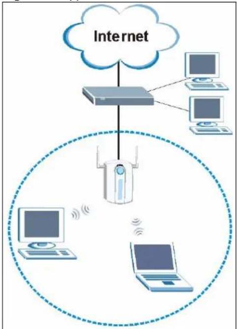
The AG-220 is in wireless station mode by default. When the AG-220 works as a wireless station (wireless client), you can either set the network type to Infrastructure and connect to an AP or use Ad-Hoc mode and connect to a peer computer (another wireless device in Ad-Hoc mode).
To connect to a network via an access point (AP), set the AG-220 network type to Infrastructure. Through the AP, you can access the Internet or the wired network behind the AP.
Figure 1 Application: Infrastructure
flowchart
graph TD
    A["Internet"] --> B["Server"]
    B --> C["Desktop"]
    B --> D["Desktop"]
    B --> E["Desktop"]
    B --> F["Laptop"]
    B --> G["Laptop"]
    style A fill:#f9f,stroke:#333
    style B fill:#ccf,stroke:#333
    style C fill:#cfc,stroke:#333
    style D fill:#fcc,stroke:#333
    style E fill:#cff,stroke:#333
    style F fill:#ffc,stroke:#333
    style G fill:#cfc,stroke:#333
1.2.1.2 Ad-Hoc
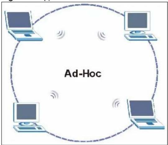
To set up a small independent wireless workgroup without an AP, use Ad-Hoc.
Ad-Hoc does not require an AP or a wired network. Two or more wireless clients communicate directly with each other.
Figure 2 Application: Ad-Hoc
flowchart
graph TD
    A["Computer 1"] --> B["Computer 2"]
    C["Computer 3"] --> D["Computer 4"]
    E["Computer 5"] --> F["Computer 6"]
    G["Computer 7"] --> H["Computer 8"]
    I["Computer 9"] --> J["Computer 10"]
    K["Computer 11"] --> L["Computer 12"]
    M["Computer 13"] --> N["Computer 14"]
    O["Computer 15"] --> P["Computer 16"]
    Q["Computer 17"] --> R["Computer 18"]
    S["Computer 19"] --> T["Computer 20"]
    U["Computer 21"] --> V["Computer 22"]
    W["Computer 23"] --> X["Computer 24"]
    Y["Computer 25"] --> Z["Computer 26"]
    AA["Computer 27"] --> AB["Computer 28"]
    AC["Computer 29"] --> AD["Computer 30"]
    AE["Computer 31"] --> AF["Computer 32"]
    AG["Computer 33"] --> AH["Computer 34"]
    AI["Computer 35"] --> AJ["Computer 36"]
    AK["Computer 37"] --> AL["Computer 38"]
    AM["Computer 39"] --> AN["Computer 40"]
    AO["Computer 41"] --> AP["Computer 42"]
    AQ["Computer 43"] --> AR["Computer 44"]
    AS["Computer 45"] --> AT["Computer 46"]
    AU["Computer 47"] --> AV["Computer 48"]
    AW["Computer 49"] --> AX["Computer 50"]
1.2.2 Access Point Mode
You can also set the AG-220 to access point mode. This allows you to set up your wireless networks without using a dedicated AP. The following figure shows a network example.
Figure 3 Application: Access Point Mode
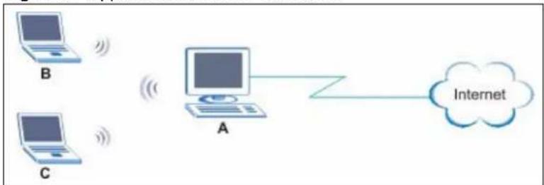
In the example, the AG-220 is installed on computer A and set to operate in access point mode. Computer A provides an Internet connection to the wireless LAN, so wireless stations B and C can access the Internet.
1.2.3 Changing AG-220 Mode
To change between the modes, select either Station Mode or AP Mode in any ZyXEL utility screens.
Note: This feature is not available in the Windows Vista utility. The Windows Vista utility only operates in Station Mode.
Figure 4 ZyXEL Utility: Change Modes
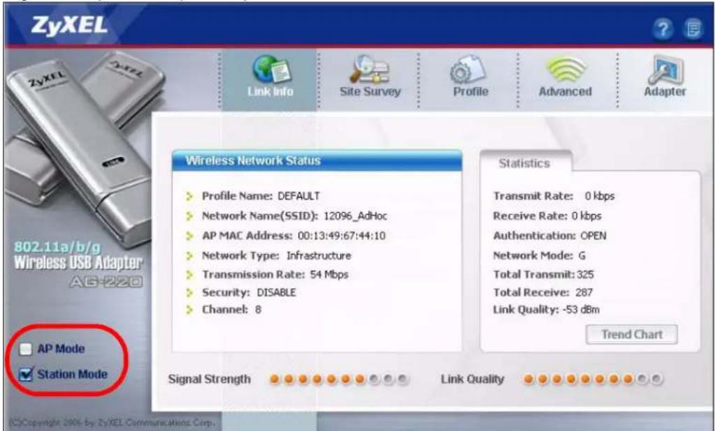
Note: Wait for about five seconds for the ZyXEL utility to complete the mode change.
The current mode is indicated by the color of the check box.
1.3 AG-220 Hardware and Utility Installation
Follow the instructions in the Quick Start Guide to install the ZyXEL utility and make hardware connections.
1.3.1 ZyXEL Utility Icon
After you install and start the ZyXEL utility, an icon for the ZyXEL utility appears in the system tray.
Note: The ZyXEL utility system tray icon displays only when the AG-220 is installed properly.
When you use the ZyXEL utility, it automatically disables Wireless Zero Configuration (WZC).
Figure 5 ZyXEL Utility: System Tray Icon
The color of the ZyXEL utility system tray icon indicates the status of the AG-220. Refer to the following table for details.
Table 1 ZyXEL Utility: System Tray Icon
| COLOR DESCRIPTION | |
| Red The AG-220 is operating in wireless station mode but is not connected to a wireless network. | |
| Green The AG-220 is operating in wireless station mode and is connected to a wireless network. | |
| Pale Blue The AG-220 is operating in access point mode. |
1.4 Configuration Methods
To configure your AG-220, use one of the following applications:
- Wireless Zero Configuration (WZC) (the Windows XP wireless configuration tool)
- ZyXEL Utility (required when you want to use the AG-220 as an access point)
Note: Do NOT use WZC at the same time you use the ZyXEL utility.
1.4.1 Enabling WZC
Note: When you use the ZyXEL utility, it automatically disables WZC.
If you want to use WZC to configure the AG-220, you need to disable the ZyXEL utility by right-clicking the utility icon (Z) in the system tray and selecting Exit.
Figure 6 Enable WZC
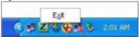
Refer to the appendices for information on how to use WZC to manage the AG-220.
To reactivate the ZyXEL utility, double-click the (Z) icon on your desktop or click Start, (All) Programs, ZyXEL AG-220 Wireless Adapter Utility, ZyXEL AG-220 Wireless Adapter Software.
1.4.2 Accessing the ZyXEL Utility
Double-click on the ZyXEL wireless LAN utility icon in the system tray to open the ZyXEL utility.
The ZyXEL utility screens are similar in all Microsoft Windows versions. Screens for Windows XP are shown in this User's Guide.
Note: Click the icon (located in the top right corner) to display the online help window.
CHAPTER 2 Tutorial
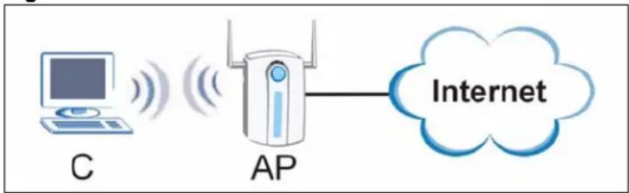
The following sections show you how to join a wireless network using the ZyXEL utility, as in the following diagrams. The wireless client is labeled C and the access point is labeled AP.
Figure 7 Infrastructure Network
flowchart
graph LR
    C["Computer"] -->|Signal| AP["AP"]
    AP -->|Internet| Cloud["Cloud"]
There are three ways to connect the wireless client (the AG-220 in station mode) to a network.
- Configure nothing and leave the wireless client to automatically scan for and connect to any available network that has no wireless security configured.
- Manually connect to a network (see Section 2.1 on page 29).
- Configure a profile to have the wireless client automatically connect to a specific network or peer computer (see Section 2.2 on page 31).
This chapter also includes a simple example of how to configure the AG-220 as an AP using the ZyXEL utility. See Section 2.3 on page 34 for more information.
2.1 Connecting to a Wireless LAN
This example illustrates how to manually connect your wireless client to an access point (AP) configured for WPA-PSK security and connected to the Internet. Before you connect to the access point, you must know its Service Set IDentity (SSID) and WPA-PSK pre-shared key. In this example, the AP's SSID is "SSID_Example3" and its pre-shared key is "ThisismyWPA-PSKpre-sharedkey".
After you install the ZyXEL utility and then insert the wireless client, follow the steps below to connect to a network using the Site Survey screen.
1 Open the ZyXEL utility and click the Site Survey tab to open the screen shown next.
Figure 8 ZyXEL Utility: Site Survey
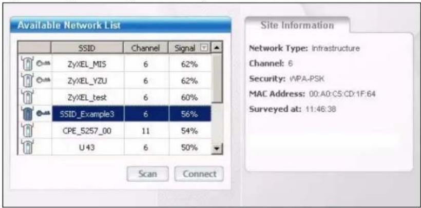
2 The wireless client automatically searches for available wireless networks. Click Scan if you want to search again. If no entry displays in the Available Network List, that means there is no wireless network available within range. Make sure the AP or peer computer is turned on, or move the wireless client closer to the AP or peer computer. See Table 5 on page 54 for detailed field descriptions.
3 To connect to an AP or peer computer, either click an entry in the list and then click Connect or double-click an entry (SSID_Example3 in this example).
4 When you try to connect to an AP with security configured, a window will pop up prompting you to specify the security settings. Enter the pre-shared key and leave the encryption type at the default setting.
Use the Next button to move on to the next screen. You can use the Back button at any time to return to the previous screen, or the Exit button to return to the Site Survey screen.
Figure 9 ZyXEL Utility: Security Settings
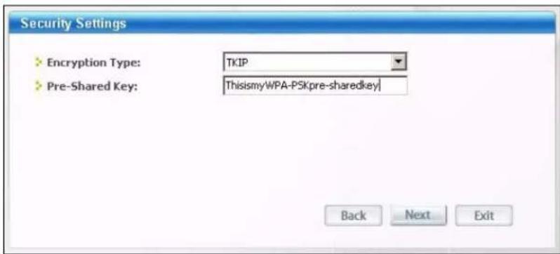
5 The Confirm Save window appears. Check your settings and click Save to continue.
Figure 10 ZyXEL Utility: Confirm Save
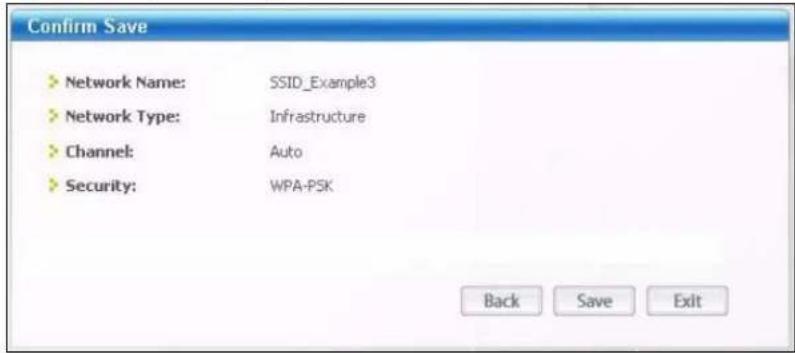
6 The ZyXEL utility returns to the Link Info screen while it connects to the wireless network using your settings. When the wireless link is established, the ZyXEL utility icon in the system tray turns green and the Link Info screen displays details of the active connection. Check the network information in the Link Info screen to verify that you have successfully connected to the selected network. If the wireless client is not connected to a network, the fields in this screen remain blank. See Table 3 on page 52 for detailed field descriptions.
Figure 11 ZyXEL Utility: Link Info
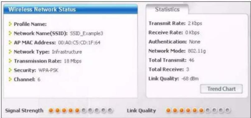
7 Open your Internet browser and enter http://www.zyxel.com or the URL of any other web site in the address bar. If you are able to access the web site, your wireless connection is successfully configured. If you cannot access the web site, check the Troubleshooting section of this User's Guide or contact your network administrator if necessary.
2.2 Creating and Using a Profile
A profile lets you automatically connect to the same wireless network every time you use the ZyXEL utility. You can also configure different profiles for different networks, for example if you connect a notebook computer to wireless networks at home and at work.
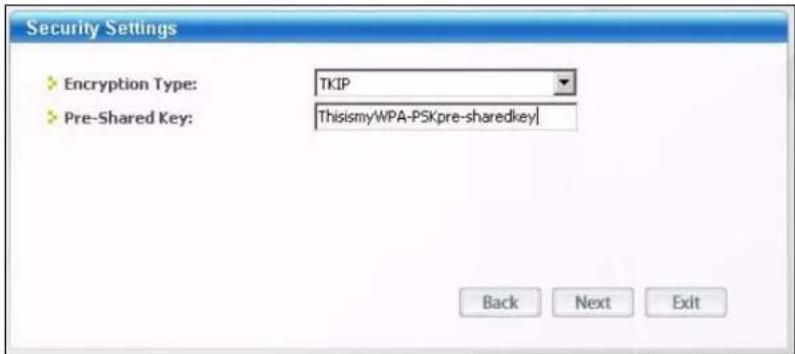
This example illustrates how to set up a profile and connect the wireless client to an access point configured for WPA-PSK security. In this example, the AP's SSID is "SSID_Example3" and its pre-shared key is "ThisismyWPA-PSKpre-sharedkey". You have chosen the profile name "PN_Example3".
1 Open the ZyXEL utility and click the Profile tab to open the screen as shown. Click Add to configure a new profile.
Figure 12 ZyXEL Utility: Profile
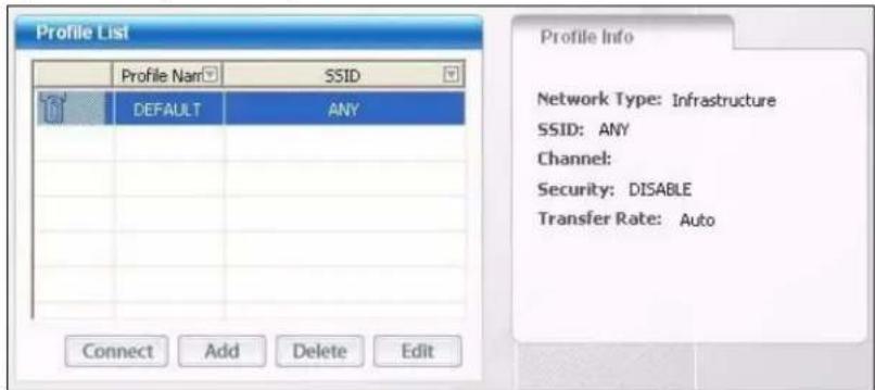
2 The Add New Profile screen appears. The wireless client automatically searches for available wireless networks, which are displayed in the Scan Info box. You can also configure your profile for a wireless network that is not in the list.
Figure 13 ZyXEL Utility: Add New Profile
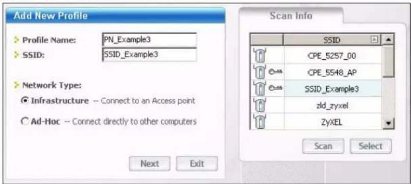
3 Give the profile a descriptive name (of up to 32 printable ASCII characters). Select Infrastructure and either manually enter or select the AP's SSID in the Scan Info table and click Select.
4 Choose the same encryption method as the AP to which you want to connect (In this example, WPA-PSK).
Figure 14 ZyXEL Utility: Profile Security
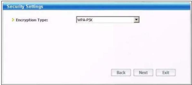
5 This screen varies depending on the encryption method you selected in the previous screen. In this example, enter the pre-shared key and leave the encryption type at the default setting.
Figure 15 ZyXEL Utility: Profile Encryption
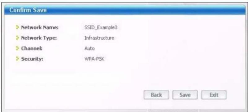
6 Verify the profile settings in the ready-only screen. Click Save to save and go to the next screen.
Figure 16 ZyXEL Utility: Profile Confirm Save
7 Click Activate Now to use the new profile immediately. Otherwise, click the Activate Later button to go back to the Profile List screen.
If you clicked Activate Later you can select the profile from the list in the Profile screen and click Connect to activate it.
Note: Only one profile can be activated and used at any given time.
Figure 17 ZyXEL Utility: Profile Activate
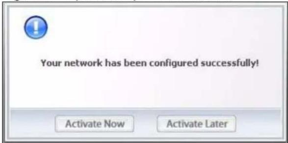
8 When you activate the new profile, the ZyXEL utility goes to the Link Info screen while it connects to the AP using your settings. When the wireless link is established, the ZyXEL utility icon in the system tray turns green and the Link Info screen displays details of the active connection.
9 Make sure the selected AP in the active profile is on and connected to the Internet. Open your Internet browser, enter http://www.zyxel.com or the URL of any other web site in the address bar and press ENTER. If you are able to access the web site, your new profile is successfully configured.
10If you cannot access the Internet, go back to the Profile screen. Select the profile you are using and click Edit. Check the details you entered previously. Also, refer to the Troubleshooting section of this User's Guide or contact your network administrator if necessary.
2.3 Configuring the AG-220 as an AP
Note: This mode is not available in the Windows Vista version of the utility.
In access point mode, your AG-220 allows you to set up your wireless network without using a dedicated AP. Refer to Section 1.2.3 on page 25 and Chapter 5 on page 73 for more information.
Note: With WZC, you cannot use the AG-220 as an access point.
After you install the ZyXEL utility and then insert the AG-220, follow the steps below to set up your AG-220 as an AP.
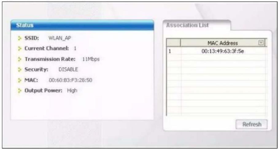
1 Select AP Mode in any utility screen and wait for five seconds. The screen changes and displays as shown next. Under Status, you can view the current settings on the AG-220. In the Association List, you can see if any wireless clients have connected to your AG-220.
Figure 18 ZyXEL Utility: AP: Link Info
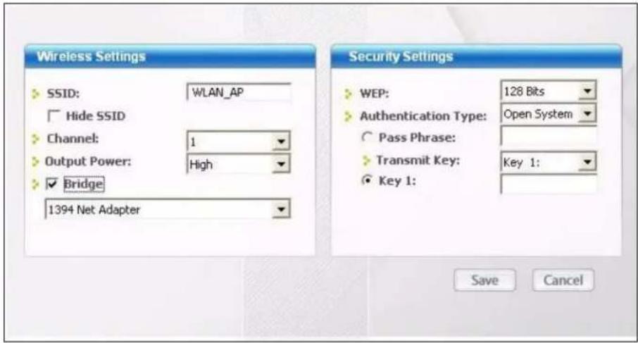
2 If you want to change the SSID and enable wireless security for your AG-220, click the Configuration tab and refer to Section 5.3 on page 75 for detailed field descriptions.
Note: Only WEP security is available when the AG-220 is in AP mode
Figure 19 ZyXEL Utility: AP: Configuration
CHAPTER 3
Wireless LAN Network
This chapter provides background information on wireless LAN networks.
3.1 Wireless LAN Overview
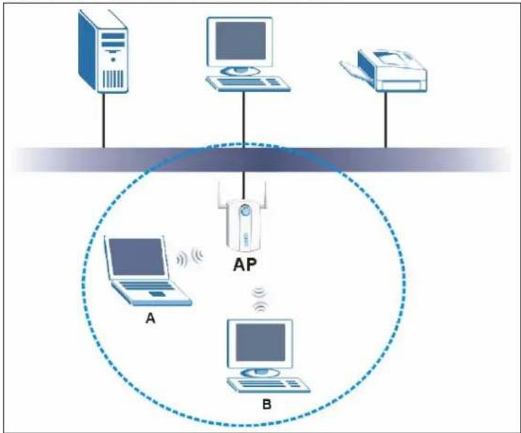
The following figure provides an example of a wireless network with an AP. See Figure 2 on page 25 for an Ad Hoc network example.
Figure 20 Example of a Wireless Network
flowchart
graph TD
    A["Computer 1"] -->|Wireless Signal| AP["AP"]
    B["Computer 2"] -->|Wireless Signal| AP
    C["Computer 3"] -->|Wireless Signal| AP
    AP -->|Wireless Signal| D["Central Network"]
    style AP stroke-dasharray: 5 5
The wireless network is the part in the blue circle. In this wireless network, devices A and B are called wireless clients. The wireless clients use the access point (AP) to interact with other devices (such as the printer) or with the Internet
Every wireless network must follow these basic guidelines.
- Every device in the same wireless network must use the same SSID.
The SSID is the name of the wireless network. It stands for Service Set IDentity.
- If two wireless networks overlap, they should use a different channel.
Like radio stations or television channels, each wireless network uses a specific channel, or frequency, to send and receive information.
- Every device in the same wireless network must use security compatible with the AP or peer computer.
Security stops unauthorized devices from using the wireless network. It can also protect the information that is sent in the wireless network.
3.2 Wireless LAN Security
Wireless LAN security is vital to your network to protect wireless communications.
Configure the wireless LAN security using the Configuration or the Profile Security Setting screen. If you do not enable any wireless security on your AG-220, the AG-220's wireless communications are accessible to any wireless networking device that is in the coverage area.
Note: You can only use WEP encryption if you set the AG-220 to Ad-hoc or AP mode.
See the appendices for more detailed information about wireless security.
3.2.1 Hide SSID
Normally, the AG-220 in AP mode acts like a beacon and regularly broadcasts the SSID in the area. You can hide the SSID instead, in which case the AG-220 in AP mode does not broadcast the SSID. In addition, you should change the default SSID to something that is difficult to guess.
This type of security is fairly weak, however, because there are ways for unauthorized wireless devices to get the SSID. In addition, unauthorized wireless devices can still see the information that is sent in the wireless network.
3.2.2 MAC Address Filter
Every device that can use a wireless network has a unique identification number, called a MAC address. ^1 A MAC address is usually written using twelve hexadecimal characters ^2 ; for example, 00A0C5000002 or 00:A0:C5:00:00:02.
To get the MAC address for each device in the wireless network, see the device's User's Guide or other documentation. You can find the MAC address of the AG-220 by looking at the sticker on the bottom of the device. Alternatively, use the utility in AP mode and look at the Link Info screen. See Section 5.2 on page 74 for more details. You can also use the Association List in the Link Info screen (in AP mode) to get the MAC addresses of other wireless devices connected to the AG-220.
You can use the MAC address filter to tell the AG-220 in AP mode which devices are allowed or not allowed to use the wireless network. If a device is allowed to use the wireless network, it still has to have the correct information (SSID, channel, and security). If a device is not allowed to use the wireless network, it does not matter if it has the correct information.
This type of security does not protect the information that is sent in the wireless network. Furthermore, there are ways for unauthorized wireless devices to get the MAC address of an authorized device. Then, they can use that MAC address to access the wireless network.
3.2.3 User Authentication and Encryption
You can make every user log in to the wireless network before they can use it. This is called user authentication. However, every wireless client in the wireless network has to support IEEE 802.1x to do this.
Wireless networks can use encryption to protect the information that is sent in the wireless network. Encryption is like a secret code. If you do not know the secret code, you cannot understand the message.
3.2.3.1 WEP
3.2.3.1.1 Data Encryption
WEP (Wired Equivalent Privacy) encryption scrambles all data packets transmitted between the AG-220 and the AP or other wireless stations to keep network communications private. Both the wireless stations and the access points must use the same WEP key for data encryption and decryption.
There are two ways to create WEP keys in your AG-220.
- Automatic WEP key generation based on a “password phrase” called a passphrase. The passphrase is case sensitive. You must use the same passphrase for all WLAN adapters with this feature in the same WLAN.
For WLAN adapters without the passphrase feature, you can still take advantage of this feature by writing down the four automatically generated WEP keys from the Security Settings screen of the ZyXEL utility and entering them manually as the WEP keys in the other WLAN adapter(s).
- Enter the WEP keys manually.
Your AG-220 allows you to configure up to four 64-bit, 128-bit or 256-bit WEP keys and only one key is used as the default key at any one time.
3.2.3.1.2 Authentication Type
The IEEE 802.11b/g standard describes a simple authentication method between the wireless stations and AP. Three authentication types are defined: Auto, Open System and Shared Key.
- Open System mode is implemented for ease-of-use and when security is not an issue. The wireless station and the AP or peer computer do not share a secret key. Thus the wireless stations can associate with any AP or peer computer and listen to any transmitted data that is not encrypted.
- Shared Key mode involves a shared secret key to authenticate the wireless station to the AP or peer computer. This requires you to enable the wireless LAN security and use same settings on both the wireless station and the AP or peer computer.
- Auto authentication mode allows the AG-220 to switch between the open system and shared key modes automatically. Use the auto mode if you do not know the authentication mode of the other wireless stations.
3.2.3.2 IEEE 802.1x
The IEEE 802.1x standard outlines enhanced security methods for both the authentication of wireless stations and encryption key management. Authentication can be done using an external RADIUS server.
3.2.3.2.1 EAP Authentication
EAP (Extensible Authentication Protocol) is an authentication protocol that runs on top of the IEEE 802.1x transport mechanism in order to support multiple types of user authentication. By using EAP to interact with an EAP-compatible RADIUS server, an access point helps a wireless station and a RADIUS server perform authentication.
The type of authentication you use depends on the RADIUS server and an intermediary AP(s) that supports IEEE 802.1x. The AG-220 supports EAP-TLS, EAP-TTLS and EAP-PEAP. Refer to Appendix D on page 115 for descriptions.
For EAP-TLS authentication type, you must first have a wired connection to the network and obtain the certificate(s) from a certificate authority (CA). Certificates (also called digital IDs) can be used to authenticate users and a CA issues certificates and guarantees the identity of each certificate owner.
3.2.3.3 WPA and WPA2
Wi-Fi Protected Access (WPA) is a subset of the IEEE 802.11i standard. WPA2 (IEEE 802.11i) is a wireless security standard that defines stronger encryption, authentication and key management than WPA.
Key differences between WPA(2) and WEP are improved data encryption and user authentication.
Both WPA and WPA2 improve data encryption by using Temporal Key Integrity Protocol (TKIP), Message Integrity Check (MIC) and IEEE 802.1x. WPA and WPA2 use Advanced Encryption Standard (AES) in the Counter mode with Cipher block chaining Message authentication code Protocol (CCMP) to offer stronger encryption than TKIP.
If both an AP and the wireless clients support WPA2 and you have an external RADIUS server, use WPA2 for stronger data encryption. If you don't have an external RADIUS server, you should use WPA2-PSK (WPA2-Pre-Shared Key) that only requires a single (identical) password entered into each access point, wireless gateway and wireless client. As long as the passwords match, a wireless client will be granted access to a WLAN.
If the AP or the wireless clients do not support WPA2, just use WPA or WPA-PSK depending on whether you have an external RADIUS server or not.
Select WEP only when the AP and/or wireless clients do not support WPA or WPA2. WEP is less secure than WPA or WPA2.
3.3 WiFi Protected Setup
Note: This feature is for Windows Vista only.
When using the Windows Vista ZyXEL utility your AG-220 supports WiFi Protected Setup (WPS), which is an easy way to set up a secure wireless network. WPS is an industry standard specification, defined by the WiFi Alliance.
WPS allows you to quickly set up a wireless network with strong security, without having to configure security settings manually. Each WPS connection works between two devices. Both devices must support WPS (check each device's documentation to make sure).
Depending on the devices you have, you can either press a button (on the device itself, or in its configuration utility) or enter a PIN (a unique Personal Identification Number that allows one device to authenticate the other) in each of the two devices. When WPS is activated on a device, it has two minutes to find another device that also has WPS activated. Then, the two devices connect and set up a secure network by themselves.
3.3.1 Push Button Configuration
WPS Push Button Configuration (PBC) is initiated by pressing a button on each WPS-enabled device, and allowing them to connect automatically. You do not need to enter any information.
Not every WPS-enabled device has a physical WPS button. Some may have a WPS PBC button in their configuration utilities instead of or in addition to the physical button.
Take the following steps to set up WPS using the button.
1 Ensure that the two devices you want to set up are within wireless range of one another.
2 Look for a WPS button on each device. If the device does not have one, log into its configuration utility and locate the button (see the device's User's Guide for how to do this - for the AG-220, see Section 4.7 on page 68).
3 Press the button on one of the devices (it doesn't matter which).
4 Within two minutes, press the button on the other device. The registrar sends the network name (SSID) and security key through an secure connection to the enrollee.
If you need to make sure that WPS worked, check the list of associated wireless clients in the AP's configuration utility. If you see the wireless client in the list, WPS was successful.
3.3.2 PIN Configuration
Each WPS-enabled device has its own PIN (Personal Identification Number). This may either be static (it cannot be changed) or dynamic (in some devices you can generate a new PIN by clicking on a button in the configuration interface).
Use the PIN method instead of the push-button configuration (PBC) method if you want to ensure that the connection is established between the devices you specify, not just the first two devices to activate WPS in range of each other. However, you need to log into the configuration interfaces of both devices to use the PIN method.
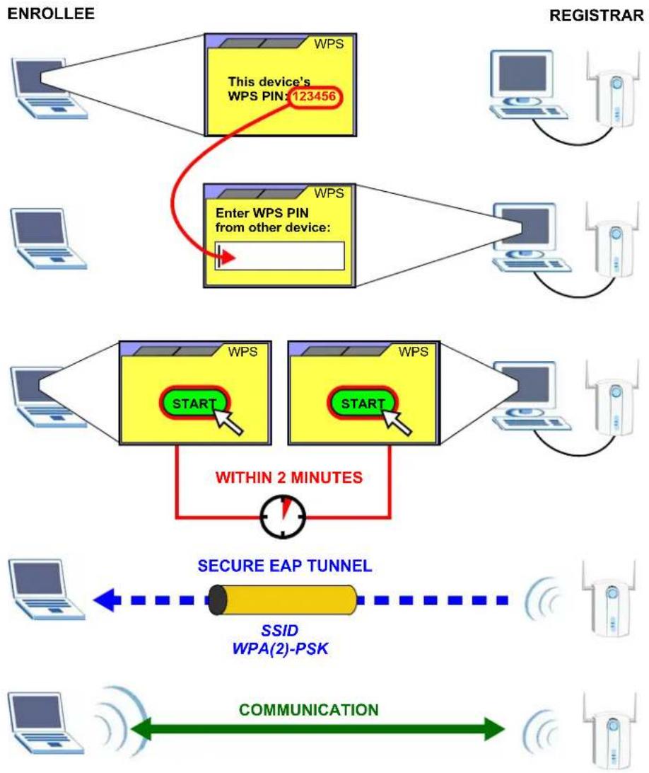
When you use the PIN method, you must enter the PIN from one device (usually the wireless client) into the second device (usually the Access Point or wireless router). Then, when WPS is activated on the first device, it presents its PIN to the second device. If the PIN matches, one device sends the network and security information to the other, allowing it to join the network.
Take the following steps to set up a WPS connection between an access point or wireless router (referred to here as the AP) and a client device using the PIN method.
1 Ensure WPS is enabled on both devices.
2 Access the WPS section of the AP's configuration interface. See the device's User's Guide for how to do this.
3 Look for the client's WPS PIN; it will be displayed either on the device, or in the WPS section of the client's configuration interface (see the device's User's Guide for how to find the WPS PIN - for the AG-220, see Section 3.3.1 on page 41).
4 Enter the client's PIN in the AP's configuration interface.
Note: If the client device's configuration interface has an area for entering another device's PIN, you can either enter the client's PIN in the AP, or enter the AP's PIN in the client - it does not matter which.
5 Start WPS on both devices within two minutes.
Note: Use the configuration utility to activate WPS, not the push-button on the device itself.
6 On a computer connected to the wireless client, try to connect to the Internet. If you can connect, WPS was successful.
If you cannot connect, check the list of associated wireless clients in the AP's configuration utility. If you see the wireless client in the list, WPS was successful.
The following figure shows a WPS-enabled wireless client (installed in a notebook computer) connecting to the WPS-enabled AP via the PIN method.
Figure 21 Example WPS Process: PIN Method
flowchart
graph TD
    A["ENROLLEE"] --> B["This device's WPS PIN: 123456"]
    B --> C["Enter WPS PIN from other device:"]
    C --> D["Within 2 MINUTES"]
    D --> E["SECURE EAP TUNNEL"]
    E --> F["SSID WPA(2)-PSK"]
    F --> G["COMMUNICATION"]
    G --> H["Computer"]
    I["REGISTRAR"] --> J["WPS"]
    J --> K["Start"]
    K --> L["Enter WPS PIN from other device:"]
    L --> M["Within 2 MINUTES"]
    M --> N["SET Server"]
    style A fill:#f9f,stroke:#333
    style I fill:#f9f,stroke:#333
    style B fill:#ff0,stroke:#333
    style C fill:#ff0,stroke:#333
    style D fill:#ff0,stroke:#333
    style E fill:#fff,stroke:#333
    style F fill:#fff,stroke:#333
    style G fill:#fff,stroke:#333
    style H fill:#fff,stroke:#333
3.3.3 How WPS Works
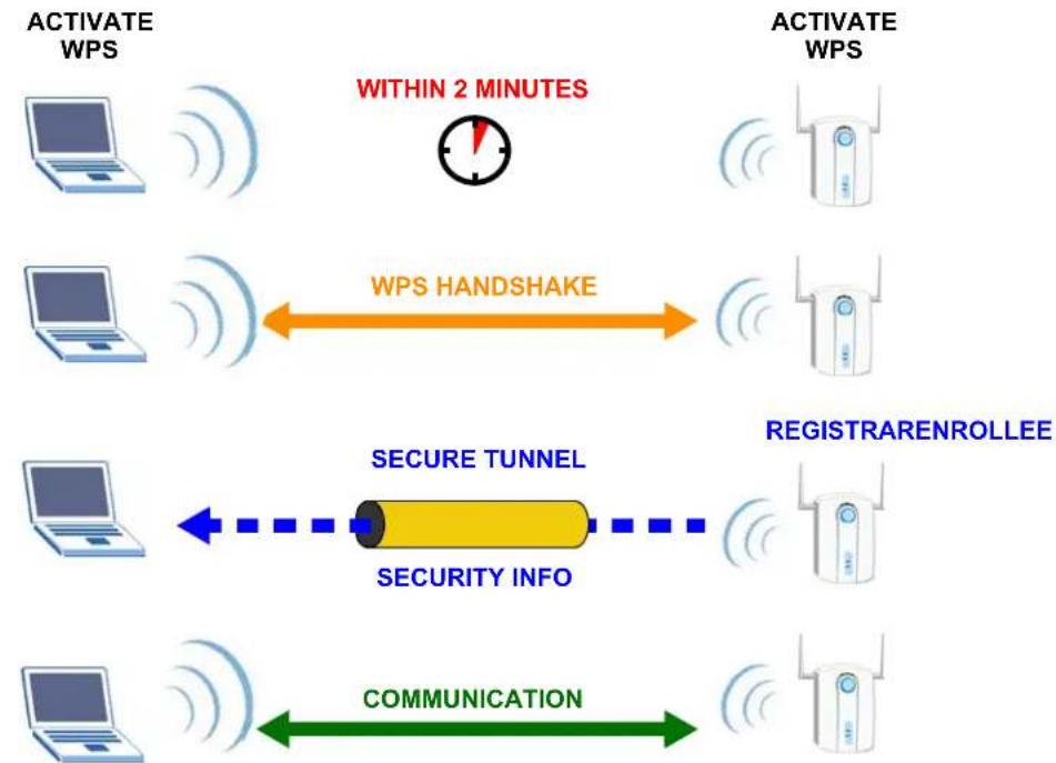
When two WPS-enabled devices connect, each device must assume a specific role. One device acts as the registrar (the device that supplies network and security settings) and the other device acts as the enrollee (the device that receives network and security settings. The registrar creates a secure EAP (Extensible Authentication Protocol) tunnel and sends the network name (SSID) and the WPA-PSK or WPA2-PSK pre-shared key to the enrollee. Whether WPA-PSK or WPA2-PSK is used depends on the standards supported by the devices. If the registrar is already part of a network, it sends the existing information. If not, it generates the SSID and WPA(2)-PSK randomly.
The following figure shows a WPS-enabled client (installed in a notebook computer) connecting to a WPS-enabled access point.
Figure 22 How WPS works
flowchart
graph LR
    A["ACTIVATE WPS"] --> B["WITHIN 2 MINUTES"]
    B --> C["WPS HANDSHAKE"]
    C --> D["ACTIVATE WPS"]
    D --> E["SECURE TUNNEL"]
    E --> F["SECURITY INFO"]
    F --> G["COMMUNICATION"]
    G --> H["ACTIVATE WPS"]
The roles of registrar and enrollee last only as long as the WPS setup process is active (two minutes). The next time you use WPS, a different device can be the registrar if necessary.
The WPS connection process is like a handshake; only two devices participate in each WPS transaction. If you want to add more devices you should repeat the process with one of the existing networked devices and the new device.
Note that the access point (AP) is not always the registrar, and the wireless client is not always the enrollee. All WPS-certified APs can be a registrar, and so can some WPS-enabled wireless clients.
By default, a WPS devices is “unconfigured”. This means that it is not part of an existing network and can act as either enrollee or registrar (if it supports both functions). If the registrar is unconfigured, the security settings it transmits to the enrollee are randomly-generated. Once a WPS-enabled device has connected to another device using WPS, it becomes “configured”. A configured wireless client can still act as enrollee or registrar in subsequent WPS connections, but a configured access point can no longer act as enrollee. It will be the registrar in all subsequent WPS connections in which it is involved. If you want a configured AP to act as an enrollee, you must reset it to its factory defaults.
3.3.3.1 Example WPS Network Setup
This section shows how security settings are distributed in an example WPS setup.
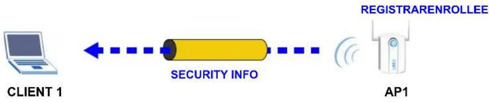
The following figure shows an example network. In step 1, both AP1 and Client 1 are unconfigured. When WPS is activated on both, they perform the handshake. In this example, AP1 is the registrar, and Client 1 is the enrollee. The registrar randomly generates the security information to set up the network, since it is unconfigured and has no existing information.
Figure 23 WPS: Example Network Step 1
flowchart
graph LR
    A["CLIENT 1"] -->|Data Transfer| B["SECURITY INFO"]
    B --> C["AP1"]
    D["REGISTRARENROLLEE"] -->|Data Transfer| B
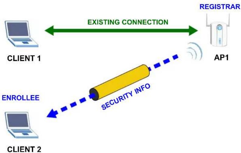
In step 2, you add another wireless client to the network. You know that Client 1 supports registrar mode, but it is better to use AP1 for the WPS handshake with the new client since you must connect to the access point anyway in order to use the network. In this case, AP1 must be the registrar, since it is configured (it already has security information for the network). AP1 supplies the existing security information to Client 2.
Figure 24 WPS: Example Network Step 2
flowchart
graph LR
    A["CLIENT 1"] -->|EXISTING CONNECTION| B["AP1"]
    C["CLIENT 2"] -->|ENROLLEE| D["SECURITY INFO"]
    D --> B
    B --> E["REGISTRAR"]
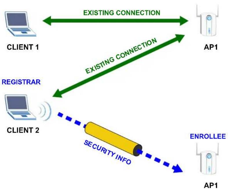
In step 3, you add another access point (AP2) to your network. AP2 is out of range of AP1, so you cannot use AP1 for the WPS handshake with the new access point. However, you know that Client 2 supports the registrar function, so you use it to perform the WPS handshake instead.
Figure 25 WPS: Example Network Step 3
flowchart
graph TD
    A["CLIENT 1"] <-->|EXISTING CONNECTION| B["AP1"]
    C["CLIENT 2"] <-->|EXISTING CONNECTION| B
    D["REGISTRAR"] --> C
    E["SECURITY INFO"] --> C
    F["ENROLLEE"] --> B
3.3.4 Limitations of WPS
WPS has some limitations of which you should be aware.
- WPS works in Infrastructure networks only (where an AP and a wireless client communicate). It does not work in Ad-Hoc networks (where there is no AP).
- When you use WPS, it works between two devices only. You cannot enroll multiple devices simultaneously, you must enroll one after the other.
For instance, if you have two enrollees and one registrar you must set up the first enrollee (by pressing the WPS button on the registrar and the first enrollee, for example), then check that it successfully enrolled, then set up the second device in the same way.
- WPS works only with other WPS-enabled devices. However, you can still add non-WPS devices to a network you already set up using WPS.
WPS works by automatically issuing a randomly-generated WPA-PSK or WPA2-PSK pre-shared key from the registrar device to the enrollee device. Whether the network uses WPA-PSK or WPA2-PSK depends on the device. You can check the configuration interface of the registrar device to discover the key the network is using (if the device supports this feature). Then, you can enter the key into the non-WPS device and join the network as normal (the non-WPS device must also support WPA-PSK or WPA2-PSK).
- When you use the PBC method, there is a short period (from the moment you press the button on one device to the moment you press the button on the other device) when any WPS-enabled device could join the network. This is because the registrar has no way of identifying the “correct” enrollee, and cannot differentiate between your enrollee and a rogue device. This is a possible way for a hacker to gain access to a network.
You can easily check to see if this has happened. WPS works between only two devices simultaneously, so if another device has enrolled your device will be unable to enroll, and will not have access to the network. If this happens, open the access point's configuration interface and look at the list of associated clients (usually displayed by MAC address). It does not matter if the access point is the WPS registrar, the enrollee, or was not involved in the WPS handshake; a rogue device must still associate with the access point to gain access to the network. Check the MAC addresses of your wireless clients (usually printed on a label on the bottom of the device). If there is an unknown MAC address you can remove it or reset the AP.
3.4 Introduction to OTIST
In a wireless network, the wireless clients must have the same SSID and security settings as the access point (AP) or wireless router (we will refer to both as “AP” here) in order to associate with it. Traditionally this meant that you had to configure the settings on the AP and then manually configure the exact same settings on each wireless client.
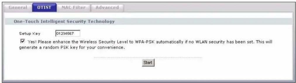
OTIST (One-Touch Intelligent Security Technology) allows you to transfer your AP's SSID and WEP or WPA-PSK security settings to wireless clients that support OTIST and are within transmission range. You can also choose to have OTIST generate a WPA-PSK key for you if you didn't configure one manually.
3.4.1 Enabling OTIST
You must enable OTIST on both the AP and wireless client before you start transferring settings.
We use the P-334U in this guide as the example AP. Screens may vary slightly for your ZyXEL devices.
Note: The AP and wireless client(s) MUST use the same Setup key.
3.4.1.1 AP
On the P-334U, you can enable OTIST using the OTIST button or the web configurator. If you use the OTIST button, the default (01234567) or previous saved (through the web configurator) Setup key is used to encrypt the settings that you want to transfer.
Hold in the OTIST button for about two seconds.
In the web configurator, go to the Wireless LAN main screen and then select OTIST. To change the Setup key, enter zero to eight printable characters. To have OTIST automatically generate a WPA-PSK key, select the Yes! check box. If you manually configured a WEP key or a WPA-PSK key and you also selected this check box, then the key you manually configured is used.
3.4.1.2 Wireless Client
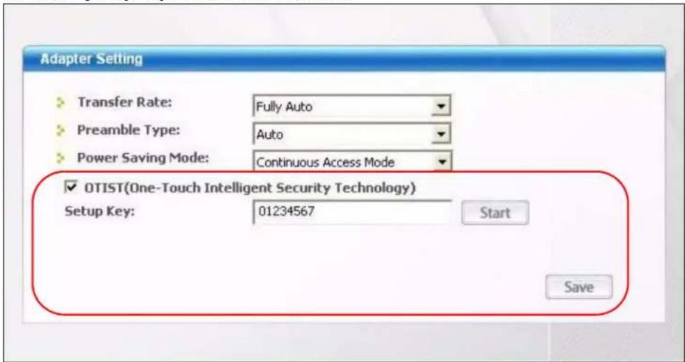
Start the ZyXEL utility and click the Adapter tab. Select the OTIST check box, enter the same Setup Key as your AP and click Save.
3.4.2 Starting OTIST
Note: You must click Start in the AP OTIST web configurator screen and in the wireless client(s) Adapter screen all within three minutes (at the time of writing). You can start OTIST in the wireless clients and AP in any order but they must all be within range and have OTIST enabled.
1 In the AP, a web configurator screen pops up showing you the security settings to transfer. After reviewing the settings, click OK.
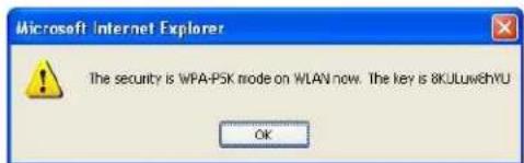
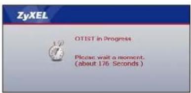
2 This screen appears while OTIST settings are being transferred. It closes when the transfer is complete.
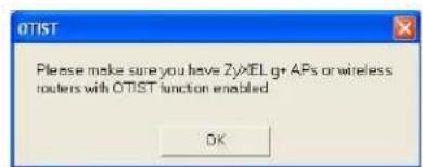
- In the wireless client, you see this screen if it can't find an OTIST-enabled AP (with the same Setup key). Click OK to go back to the ZyXEL utility main screen.
- If there is more than one OTIST-enabled AP within range, you see a screen asking you to select one AP to get settings from.
3.4.3 Notes on OTIST
1 If you enabled OTIST in the wireless client, you see this screen each time you start the utility. Click Yes for it to search for an OTIST-enabled AP.
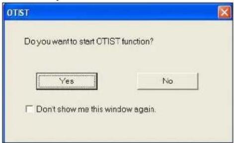
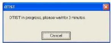
2 If an OTIST-enabled wireless client loses its wireless connection for more than ten seconds, it will search for an OTIST-enabled AP for up to one minute. (If you manually have the wireless client search for an OTIST-enabled AP, there is no timeout; click Cancel in the OTIST progress screen to stop the search.)
3 When the wireless client finds an OTIST-enabled AP, you must still click Start in the AP OTIST web configurator screen or hold in the Reset button (for one or two seconds) for the AP to transfer settings.
4 If you change the SSID or the keys on the AP after using OTIST, you need to run OTIST again or enter them manually in the wireless client(s).
5 If you configure OTIST to generate a WPA-PSK key, this key changes each time you run OTIST. Therefore, if a new wireless client joins your wireless network, you need to run OTIST on the AP and ALL the wireless clients again.
CHAPTER 4
Wireless Station Mode Configuration
This chapter shows you how to configure your AG-220 in wireless station mode. See Chapter 5 on page 73 for how to configure the AG-220 in access point mode.
4.1 Wireless Station Mode Overview
To set your AG-220 to wireless station mode, select Station Mode in any utility screen (refer to Section 1.2.3 on page 25).
4.1.1 ZyXEL Utility Screen Summary
This section describes the ZyXEL utility screens when the AG-220 is in station mode.
Figure 26 ZyXEL Utility Menu Summary: Station Mode

The following table describes the menus.
Table 2 ZyXEL Utility Menu Summary: Station Mode
| TAB DESCRIPTION | |
| Station Mode | |
| Link Info Use this screen to see your current connection status, configuration and data rate statistics. | |
| Site Survey Use this screen to• scan for a wireless network• configure wireless security (if activated on the selected network).• connect to a wireless network. | |
| Profile | Use this screen to add, delete, edit or activate a profile with a set of wireless and security settings. |
| Advanced Use this screen to change the wireless network mode. | |
| Adapter Use this screen to configure a transfer rate, enable power saving and use OTIST (One-Touch Intelligent Security Technology). | |
4.2 The Link Info Screen
When the ZyXEL utility starts, the Link Info screen displays, showing the current configuration and connection status of your AG-220.
Figure 27 Station Mode: Link Info
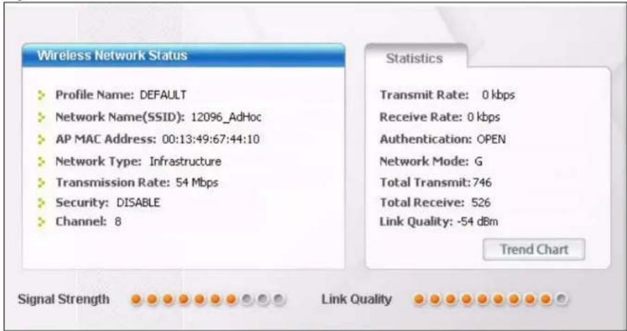
The following table describes the labels in this screen.
Table 3 Station Mode: Link Info
| LABEL DESCRIPTION | |
| AP Mode Station Mode | Use the check box to set the AG-220 to operate in wireless station or access point mode. Refer to Section 1.2.3 on page 25 for more information. |
| Wireless Network Status | |
| Profile Name This is | the name of the profile you are currently using. |
| Network Name (SSID) | The SSID identifies the wireless network to which a wireless station is associated. This field displays the name of the wireless device to which the AG-220 is associated. |
| AP MAC Address | This field displays the MAC address of the AP or peer computer to which the AG-220 is associated. |
| Network Type | This field displays the network type (Infrastructure or Ad-Hoc) of the wireless network. |
| Transmission Rate | This field displays the current transmission rate of the AG-220 in megabits per second (Mbps). |
| Security | This field displays whether data encryption is activated (WEP (WEP or 802.1x), TKIP (WPA/WPA-PSK/WPA2/WPA2-PSK), AES (WPA/WPA-PSK/WPA2/WPA2-PSK)) or inactive (DISABLE). |
| Channel This field displays the radio channel the AG-220 is currently using. | |
| Statistics | |
| Transmit Rate | This field displays the current data transmission rate in kilobits per second (Kbps). |
| Receive Rate | This field displays the current data receiving rate in kilobits per second (Kbps). |
| LABEL DESCRIPTION | |
| Authentication This | field displays the authentication method of the AG-220. |
| Network Mode | This field displays the wireless standard (A, B or G) of the AP or peer computer. |
| Total Transmit This | field displays the total number of data frames transmitted. |
| Total Receive This | field displays the total number of data frames received. |
| Link Quality This field displays the signal strength of the AG-220. | |
| Trend Chart | Click this button to display the real-time statistics of the data rate in kilobits per second (Kbps). |
| Signal Strength | The status bar shows the strength of the signal. The signal strength mainly depends on the antenna output power and the distance between your AG-220 and the AP or peer computer. |
| Link Quality | The status bar shows the quality of wireless connection. This refers to the percentage of packets transmitted successfully. If there are too many wireless stations in a wireless network, collisions may occur which could result in a loss of messages even though you have high signal strength. |
4.2.1 Trend Chart
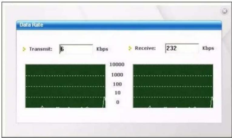
Click Trend Chart in the Link Info screen to display a screen as shown below. Use this screen to view real-time data traffic statistics.
Figure 28 Station Mode: Link Info: Trend Chart
bar
| Data Rate | Transmit (Kbps) | Receive (Kbps) | | --------- | --------------- | -------------- | | Value | 6 | 232 |The following table describes the labels in this screen.
Table 4 Station Mode: Link Info: Trend Chart
| LABEL DESCRIPTION | |
| Transmit This field displays the current data transmission rate in kilobits per second (Kbps). | |
| Receive | This field displays the current data receiving rate in kilobits per second (Kbps). |
4.3 The Site Survey Screen
Use the Site Survey screen to scan for and connect to a wireless network automatically.
Figure 29 Station Mode: Site Survey
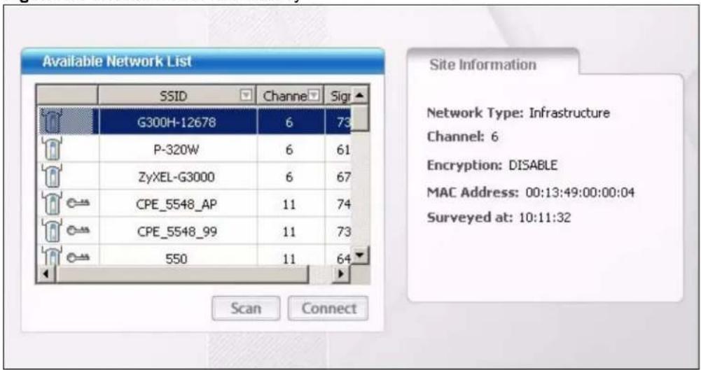
The following table describes the labels in this screen.
Table 5 Station Mode: Site Survey
| LABEL DESCRIPTION | |
| Available Network List | Click a column heading to sort the entries. |
 , ,  or or   | denotes that the wireless device is in infrastructure mode and the wireless security is activated.denotes that the wireless device is in infrastructure mode but the wireless security is deactivated.denotes that the wireless device is in Ad-Hoc mode and the wireless security is activated.denotes that the wireless device is in Ad-Hoc mode but the wireless security is deactivated. |
| SSID | This field displays the SSID (Service Set IDentifier) of each wireless device. |
| Channel This field displays the channel number used by each wireless device. | |
| Signal This field displays the signal strength of each wireless device. | |
| Scan | Click Scan to search for available wireless devices within transmission range. |
| Connect | Click Connect to associate to the selected wireless device. |
| Site Information | Click an entry in the Available Network List table to display the information of the selected wireless device. |
| Network Type | This field displays the network type (Infrastructure or Ad Hoc) of the wireless device. |
| Channel This field displays the channel number used by each wireless device. | |
| Encryption | This field shows whether data encryption is activated (WEP (WEP or 802.1x), WPA, WPA-PSK, WPA2, WPA2-PSK) or inactive (DISABLE). |
Table 5 Station Mode: Site Survey (continued)
| LABEL DESCRIPTION |
| MAC address This field displays the MAC address of the wireless device. |
| Surveyed at This field displays the time when the wireless device was scanned. |
4.3.1 Security Settings
When you configure the AG-220 to connect to a network with wireless security activated and the security settings are disabled on the AG-220, the screen varies according to the encryption method used by the selected network.
Figure 30 Station Mode: Security Setting: WEP
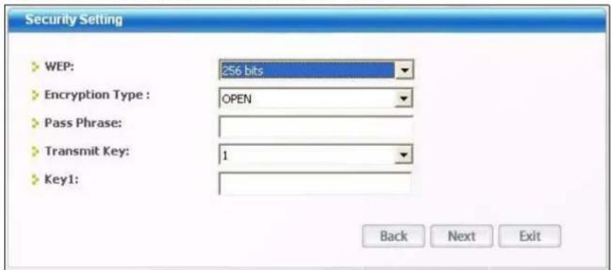
The following table describes the labels in this screen.
Table 6 Station Mode: Security Setting: WEP
| LABEL DESCRIPTION | |
| Security Settings | |
| WEP | Select 64 Bits, 128 Bits or 256 Bits to activate WEP encryption and then fill in the related fields. |
| Encryption Type | Select an authentication method. Choices are SHARED and OPEN.Refer to Section 3.2.3.1.2 on page 39 for more information. |
| Pass Phrase | Enter a passphrase of up to 63 case-sensitive printable characters. As you enter the passphrase, the AG-220 automatically generates four different WEP keys and displays it in the key field below. Refer to Section 3.2.3.1.1 on page 39 for more information.At the time of writing, you cannot use the passphrase function to generate 256-bit WEP keys. |
| Transmit Key | Select a default WEP key to use for data encryption. The key displays in the field below. |
| LABEL DESCRIPTION | |
| Key x (where x is a number between 1 and 4) | Select this option if you want to manually enter the WEP keys. Enter the WEP key in the field provided.If you select64 Bitsin the WEP field.Enter either 10 hexadecimal digits in the range of “A-F”, “a-f” and “0-9” (for example, 11AA22BB33) for HEX key type.orEnter 5 ASCII characters (case sensitive) ranging from “a-z”, “A-Z” and “0-9” (for example, MyKey) for ASCII key type.If you select128 Bitsin the WEP field,Enter either 26 hexadecimal digits in the range of “A-F”, “a-f” and “0-9” (for example, 00112233445566778899AABBCC) for HEX key typeorEnter 13 ASCII characters (case sensitive) ranging from “a-z”, “A-Z” and “0-9” (for example, MyKey12345678) for ASCII key type.If you select256 Bitsin the WEP field,Enter either 58 hexadecimal digits in the range of “A-F”, “a-f” and “0-9” (for example, 0000111122223333444455556666777788889999AAAABBBBCCCC000011) for HEX key typeorEnter 29 ASCII characters (case sensitive) ranging from “a-z”, “A-Z” and “0-9” (for example, MyKey111122223333444455556678) for ASCII key type.Note:The values for the WEP keys must be set up exactly the same on all wireless devices in the same wireless LAN.ASCIIWEP keys are case sensitive. |
| Back | ClickBackto go to theSite Surveyscreen to select and connect to another network. |
| Next | ClickNextto confirm your selections and advance to theConfirm Savescreen.Refer toSection 4.3.2 on page 60. |
| Exit | ClickExitto return to theSite Surveyscreen without saving. |
4.3.1.2 WPA-PSK/WPA2-PSK
Figure 31 Station Mode: Security Setting: WPA-PSK/WPA2-PSK
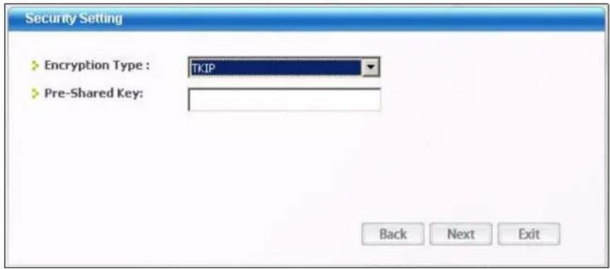
The following table describes the labels in this screen.
Table 7 Station Mode: Security Setting: WPA-PSK/WPA2-PSK
| LABEL DESCRIPTION | |
| Encryption Type The encryption mechanisms used for WPA/WPA2 and WPA-PSK/WPA2-PSK are the same. The only difference between the two is that WPA-PSK/WPA2-PSK uses a simple common password, instead of user-specific credentials.Select the encryption type (TKIP or AES) for data encryption.Refer to Section 3.2.3.3 on page 40 for more information. | |
| Pre-Shared Key | Type a pre-shared key (same as the AP or peer device) of between 8 and 63 case-sensitive ASCII characters (including spaces and symbols) or 64 hexadecimal characters. |
| Back | Click Back to go to the Site Survey screen to select and connect to another network. |
| Next | Click Next to confirm your selections and advance to the Confirm Save screen.Refer to Section 4.3.2 on page 60. |
| Exit | Click Exit to return to the Site Survey screen without saving. |
4.3.1.3 WPA/WPA2
Note: At the time of writing Login Name and Password are not available on Windows Vista.
Figure 32 Station Mode: Security Settings: WPA/WPA2
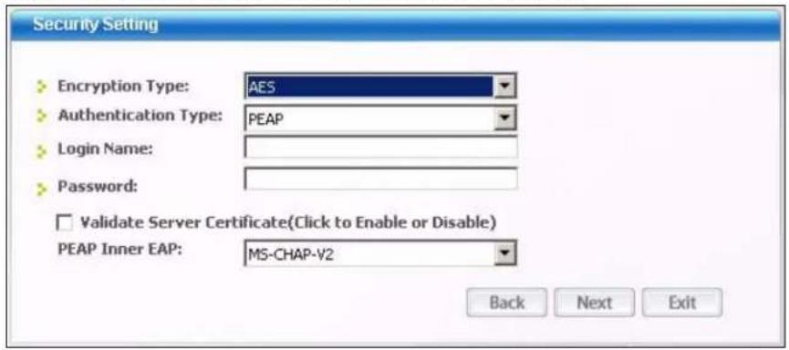
The following table describes the labels in this screen.
Table 8 Station Mode: Security Setting: WPA/WPA2
| LABEL DESCRIPTION | |
| Encryption Type The encryption mechanisms used for WPA/WPA2 and WPA-PSK/WPA2-PSK are the same. The only difference between the two is that WPA-PSK/WPA2-PSK uses a simple common password, instead of user-specific credentials.Select the encryption type (TKIP or AES) for data encryption.Refer to Section 3.2.3.3 on page 40 for more information. | |
| Authentication Type | The type of authentication you use depends on the RADIUS server or AP.Select an authentication method from the drop down list. Options are TLS and PEAP. |
Table 8 Station Mode: Security Setting: WPA/WPA2
| LABEL DESCRIPTION | |
| Login Name Enter a | user name.This is the user name that you or an administrator set up on a RADIUS server.Note: At the time of writing this field is not available on Windows Vista. |
| Password | This field is not available when you select TLS in the Authentication Type field.Enter the password associated with the user name above.Note: At the time of writing this field is not available on Windows Vista. |
| Certificate | This field is only available when you select TLS in the Authentication Type field.Click Browse to select a certificate.Note: You must first have a wired connection to a network and obtain the certificate(s) from a certificate authority (CA).Consult your network administrator for more information. |
| Validate Server Certificate | Select the check box to check the certificate of the authentication server. |
| PEAP Inner EAP | This field is only available when you select PEAP in the Authentication Type field.The PEAP method used by the RADIUS server or AP for client authentication is MS CHAP v2. |
| Back | Click Back to go to the Site Survey screen to select and connect to another network. |
| Next | Click Next to confirm your selections and advance to the Confirm Save screen.Refer to Section 4.3.2 on page 60. |
| Exit | Click Exit to return to the Site Survey screen without saving. |
4.3.1.4 IEEE 802.1x
Configure IEEE 802.1x security with various authentication methods in this screen.
Note: At the time of writing Login Name and Password are not available on Windows Vista.
Figure 33 Station Mode: Security Setting: 802.1x
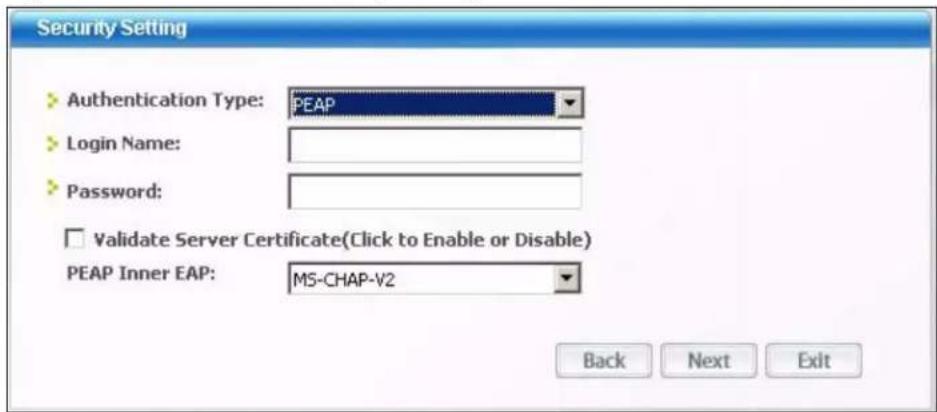
The following table describes the labels in this screen.
Table 9 Station Mode: Security Settings: IEEE 802.1x
| LABEL DESCRIPTION | |
| Authentication Type | The type of authentication you use depends on the RADIUS server or AP.Select an authentication method from the drop down list. Options are TLS and PEAP. |
| Login Name Enter a | user name.This is the user name that you or an administrator set up on a RADIUS server.Note: At the time of writing this field is not available on Windows Vista. |
| Password | This field is not available when you select TLS in the Authentication Type field.Enter the password associated with the user name above.Note: At the time of writing this field is not available on Windows Vista. |
| Certificate | This field is only available when you select TLS in the Authentication Type field.Click Browse to select a certificate.Note: You must first have a wired connection to a network and obtain the certificate(s) from a certificate authority (CA).Consult your network administrator for more information. |
| Validate Server Certificate | Select the check box to check the certificate of the authentication server. |
| PEAP Inner EAP | This field is only available when you select PEAP in the Authentication Type field.The PEAP method used by the RADIUS server or AP for client authentication is MS CHAP v2. |
| Back | Click Back to go to the Site Survey screen to select and connect to another network. |
| Next | Click Next to confirm your selections and advance to the Confirm Save screen.Refer to Section 4.3.2 on page 60. |
| Exit | Click Exit to return to the Site Survey screen without saving. |
4.3.2 Confirm Save Screen
Use this screen to confirm and save the security settings.
Figure 34 Confirm Save Screen
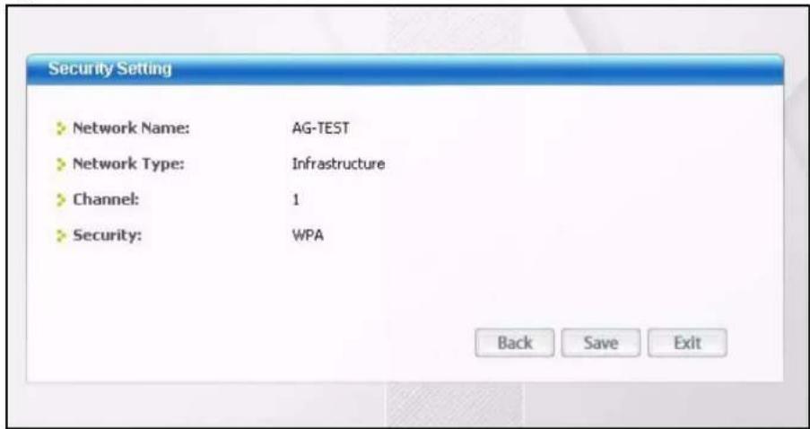
The following table describes the labels in this screen.
Table 10 Confirm Save Screen
| LABEL DESCRIPTION | |
| Security Setting | |
| Network Name | This field displays the SSID previously entered. |
| Network Type | This field displays the network type (Infrastructure or Ad-Hoc) of the wireless device. |
| Channel This field | displays the channel number used by the profile. |
| Security | This field shows whether data encryption is activated (WEP (WEP or 802.1x), WPA, WPA-PSK, WPA2, WPA2-PSK) or inactive (DISABLE). |
| Back | Click Back to return to the previous screen. |
| Save | Click Save to save the changes back to the AG-220 and display the Link Info screen. |
| Exit | Click Exit to discard changes and return to the Site Survey screen. |
4.4 The Profile Screen
A profile is a set of wireless parameters that you need to connect to a wireless network. With a profile activated, each time you start the AG-220, it automatically scans for the specific SSID and joins that network with the pre-defined wireless security settings. If the specified network is not available, the AG-220 cannot connect to a network.
If you do not configure and activate a profile, each time you start the AG-220, the AG-220 uses the default profile to connect to any available network that has no security enabled.
The default profile is a profile that allows you to connect to any SSID that has no security enabled.
Click the Profile tab in the ZyXEL utility program to display the Profile screen as shown next.
The profile function allows you to save the wireless network settings in this screen, or use one of the pre-configured network profiles.
Figure 35 Station Mode: Profile
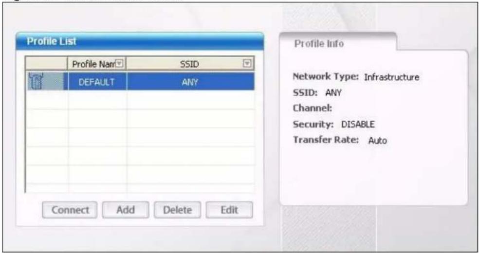
The following table describes the labels in this screen.
Table 11 Station Mode: Profile
| LABEL DESCRIPTION | ||
| Profile List Click a column heading to sort the entries. | ||
 , ,   or or | or |  denotes that the wireless device is in infrastructure mode and the wireless security is activated. denotes that the wireless device is in infrastructure mode and the wireless security is activated. denotes that the wireless device is in infrastructure mode but the wireless security is deactivated. denotes that the wireless device is in infrastructure mode but the wireless security is deactivated. denotes that the wireless device is in Ad-Hoc mode and the wireless security is activated. denotes that the wireless device is in Ad-Hoc mode and the wireless security is activated. denotes that the wireless device is in Ad-Hoc mode but the wireless security is deactivated. denotes that the wireless device is in Ad-Hoc mode but the wireless security is deactivated. |
| Profile Name This is the name of the pre-configured profile. | ||
| SSID This is the SSID of the wireless network to which the selected profile associate. | ||
| Connect To use and activate a previously saved network profile, select a pre-configured profile name in the table and click Connect. | ||
| Add To add a new profile into the table, click Add. | ||
| Delete To delete an existing wireless network configuration, select a profile in the table and click Delete. | ||
| Edit | To edit an existing wireless network configuration, select a profile in the table and click Edit. | |
| Profile Info The following fields display detailed information of the selected profile in the Profile List table. | ||
| Network Type | This field displays the network type (Infrastructure or Ad-Hoc) of the profile. | |
Table 11 Station Mode: Profile (continued)
| LABEL DESCRIPTION | |
| SSID This field displays the SSID (Service Set IDentifier) of the profile. | |
| Channel This field displays the channel number used by the profile. | |
| Security | This field shows whether data encryption is activated (WEP (WEP or 802.1x), WPA, WPA-PSK, WPA2, WPA2-PSK) or inactive (DISABLE). |
| Transfer Rate | This field displays the transmission speed of the selected profile in megabits per second (Mbps). |
4.4.1 Adding a New Profile
Follow the steps below to add a new profile.
1 Click Add in the Profile screen. An Add New Profile screen displays as shown next. Click Next to continue.
Figure 36 Station Mode: Profile: Add a New Profile
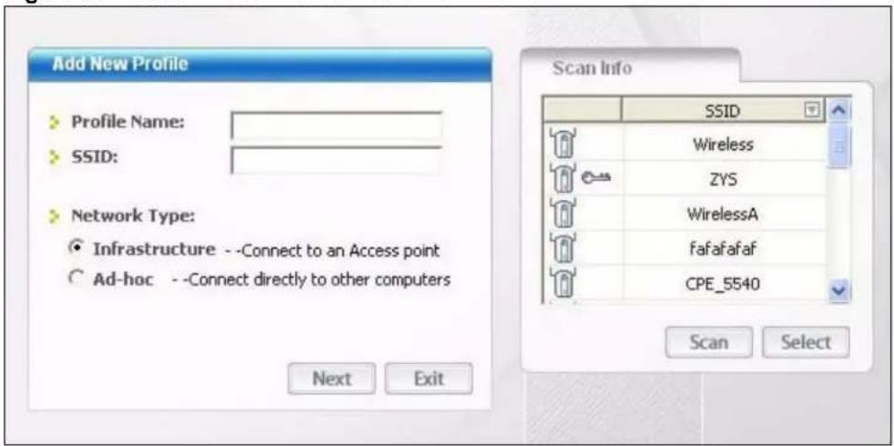
The following table describes the labels in this screen.
Table 12 Station Mode: Profile: Add a New Profile
| LABEL DESCRIPTION | |
| Add New Profile | |
| Profile Name Enter | a descriptive name in this field. |
| SSID | Select an available wireless device in the Scan Info table and click Select, or enter the SSID of the wireless device to which you want to associate in this field manually. Otherwise, enter Any to have the AG-220 associate to any AP or roam between any infrastructure wireless networks. |
| Network Type | Select Infrastructure to associate to an AP. Select Ad-Hoc to associate to a peer computer. |
| Next Click Next to go to the next screen. | |
| Exit | Click Exit to go back to the previous screen without saving. |
| LABEL DESCRIPTION | |
| Scan Info This table | displays the information of the available wireless networks within the transmission range. |
 or or  |  denotes that the wireless device is in infrastructure mode and the wireless security is activated. denotes that the wireless device is in infrastructure mode and the wireless security is activated. denotes that the wireless device is in infrastructure mode but the wireless security is deactivated. denotes that the wireless device is in infrastructure mode but the wireless security is deactivated. |
| SSID This field displays the SSID (Service Set IDentifier) of each AP or peer device. | |
| Scan | Click Scan to search for available wireless devices within transmission range. |
| Select | Select an available wireless device in the table and click Select to add it to this profile.Whenever you activate this profile, the AG-220 associates to the selected wireless network only. |
2 If you select the Infrastructure network type in the previous screen, skip to step 3. If you select the Ad-Hoc network type in the previous screen, a screen displays as follows.
Select a channel number and click Next to continue. If you are using Windows Vista this screen will not display, skip to step 3.
Note: To associate to an ad-hoc network, you must use the same channel as the peer computer.
Figure 37 Station Mode: Profile: Select a Channel
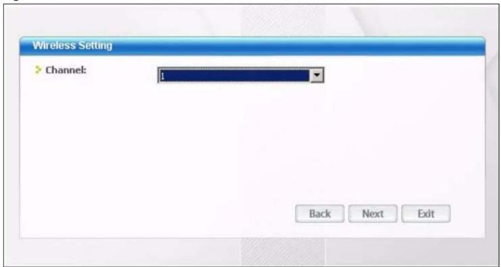
The following table describes the labels in this screen.
Table 13 Station Mode: Profile: Select a Channel
| LABEL DESCRIPTION | |
| Wireless Settings | |
| Channel Select a channel number from the drop-down list box. To associate to an ad-hoc network, you must use the same channel as the peer computer. | |
3 If you selected Infrastructure network type in the first screen, select WEP, WPA, WPA2, WPA-PSK, WPA2-PSK or 802.1x from the drop-down list box to enable data encryption. If you selected Ad-Hoc network type in the first screen, you can only use WEP encryption method. Otherwise, select DISABLE to allow the AG-220 to communicate with the access points or other peer wireless computers without any data encryption, and skip to step 5.
Figure 38 Station Mode: Profile: Wireless Settings
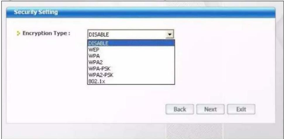
4 The screen varies depending on the encryption method you select in the previous screen. The settings must be exactly the same on the APs or other peer wireless computers as they are on the AG-220. Refer to Section 4.3.1 on page 55 for detailed information on wireless security configuration.
Figure 39 Station Mode: Profile: Security Settings
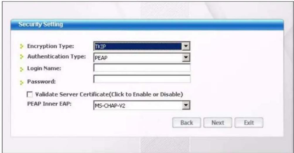
5 This read-only screen shows a summary of the new profile settings. Verify that the settings are correct. Click Save to save and go to the next screen. Click Back to return to the previous screen. Otherwise, click Exit to go back to the Profile screen without saving.
Figure 40 Station Mode: Profile: Confirm New Settings
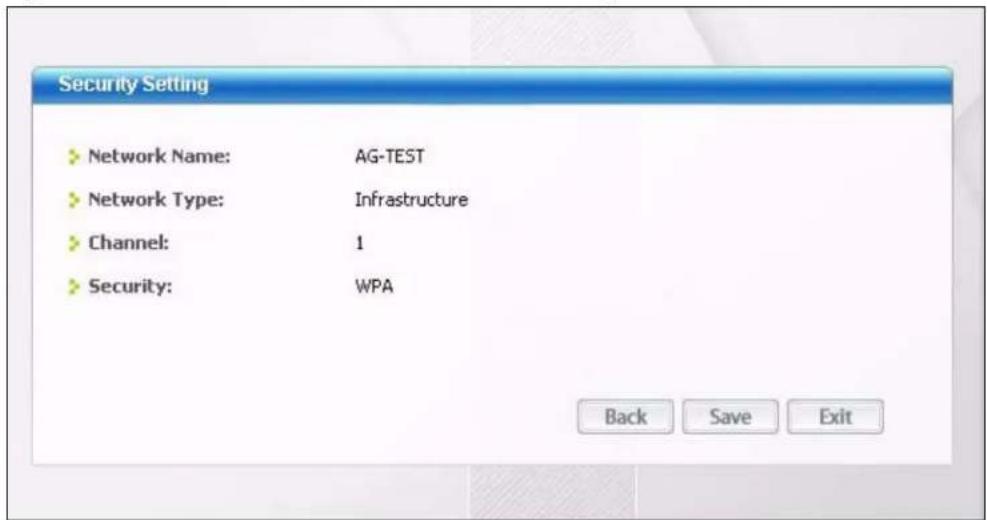
6 To use this network profile, click the Activate Now button. Otherwise, click the Activate Later button. You can activate only one profile at a time.
Note: Once you activate a profile, the ZyXEL utility will use that profile the next time it is started.
Figure 41 Station Mode: Profile: Activate the Profile
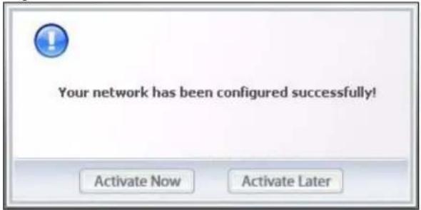
4.5 The Advanced Screen
To set the network mode of the AG-220, click the Advanced tab.
Note: This screen is not available in Windows Vista.
Figure 42 Station Mode: Advanced
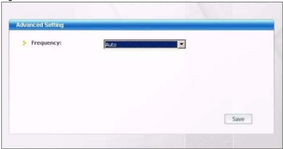
The following table describes the labels in this screen.
Table 14 Station Mode: Advanced
| LABEL DESCRIPTION | |
| Advanced Setting | |
| Frequency | Choose a network mode. Select Auto (default) to have your AG-220 automatically connect to other wireless devices in IEEE 802.11a, b or g modes. Select 11a to have your AG-220 connect to other wireless devices in IEEE 802.11a mode only, or 11b+11g to have your AG-220 connect to other wireless devices in IEEE 802.11b and 802.11g modes only. |
| Save | Click Save to save the changes to the AG-220. If you are connected to a wireless network when changing network modes, the AG-220 will disconnect and then attempt to reestablish the connection using the new setting. |
4.6 The Adapter Screen
To set the other advanced features on the AG-220, click the Adapter tab.
Note: This screen is different in Windows Vista. Please refer to Section 4.7 on page 68 for the Windows Vista screen.
Figure 43 Station Mode: Adapter
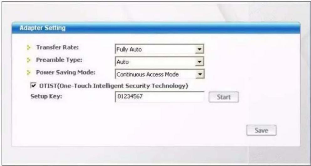
The following table describes the labels in this screen.
Table 15 Station Mode: Adapter
| LABEL DESCRIPTION | |
| Adapter Setting | |
| Transmission Rate | In most networking scenarios, the factory default Fully Auto setting is the most efficient and allows your AG-220 to operate at the highest possible transmission (data) rate.If you want to select a specific transmission rate, select one that the AP or peer wireless device supports.Note: With USB 1.0/1.1, the AG-220 can only transmit at up to 11Mbps. |
| Preamble Type Preamble is used to signal that data is coming to the receiver. Select the preamble type that the AP uses.Short preamble increases performance as less time sending preamble means more time for sending data. All IEEE 802.11b/g compliant wireless adapters support Long preamble, but not all support short preamble.Select Auto to have the AG-220 automatically use short preamble when all access point or wireless stations support it; otherwise the AG-220 uses long preamble.Note: The AG-220 and the access point or wireless stations MUST use the same preamble mode in order to communicate. | |
| LABEL DESCRIPTION | |
| Power Saving Mode | Select Maximum Power Save or Fast Power Save to save power (especially for notebook computers). This forces the AG-220 to go to sleep mode when it is not transmitting data.When you select Continuous Access Mode, the AG-220 will never go to sleep mode. |
| OTIST (One-Touch Intelligent Security Technology) | Select this check box to enable OTIST. |
| Setup Key Enter the same setup key (up to eight printable characters) as the ZyXEL AP or wireless router to which you want to associate. The default OTIST setup key is "01234567".Note: If you change the OTIST setup key on the ZyXEL AP or wireless router, you must also make the same change here. | |
| Start | Click Start to encrypt the wireless security data using the setup key and have the ZyXEL AP or wireless router set your AG-220 to use the same wireless settings as the ZyXEL AP or wireless router. You must also activate and start OTIST on the ZyXEL AP or wireless router all within three minutes. See Section 3.4 on page 47 for more information. |
| Save | Click Save to save the changes to the AG-220 and return to the Link Info screen. |
4.7 The Adapter Screen (Windows Vista)
This screen is only available in the Windows Vista version of the utility. To set the other advanced features on the AG-220, click the Adapter tab.
Figure 44 Station Mode: Adapter (Windows Vista)
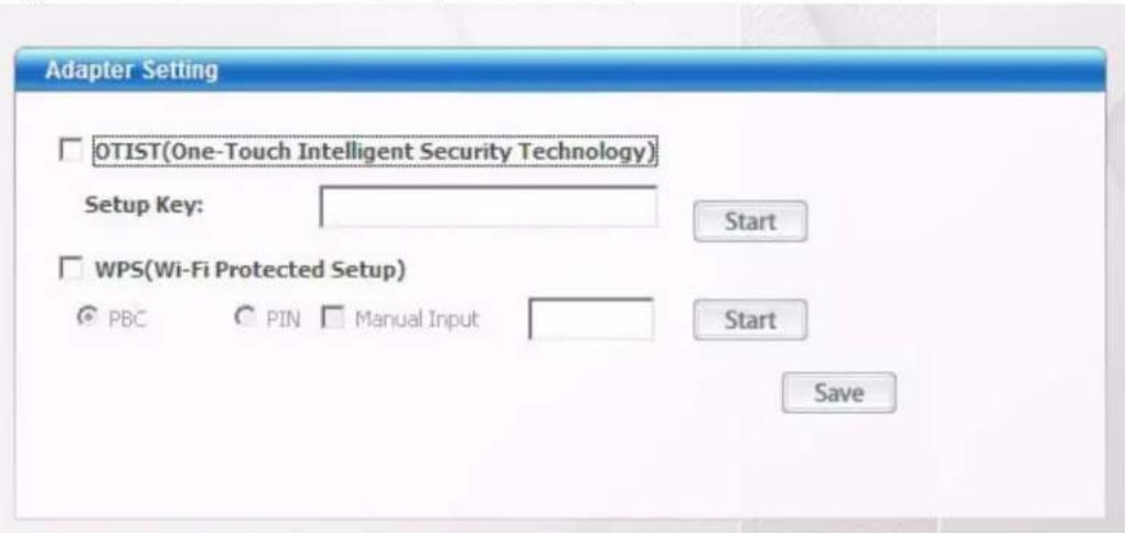
The following table describes the labels in this screen.
Table 16 Station Mode: Adapter (Windows Vista)
| LABEL DESCRIPTION | |
| Adapter Setting | |
| OTIST (One-Touch Intelligent Security Technology) | Select this check box to enable OTIST. |
| Setup Key Enter the same setup key (up to eight printable characters) as the ZyXEL AP or wireless router to which you want to associate. The default OTIST setup key is "01234567".Note: If you change the OTIST setup key on the ZyXEL AP or wireless router, you must also make the same change here. | |
| Start | Click Start to encrypt the wireless security data using the setup key and have the ZyXEL AP or wireless router set your AG-220 to use the same wireless settings as the ZyXEL AP or wireless router. You must also activate and start OTIST on the ZyXEL AP or wireless router all within three minutes. |
| WPS (Wi-Fi Protected Setup) | Select this to enable Wi-fi Protected Setup on the AG-220. |
| PBC Select this to use the PBC (Push-Button Configuration) WPS mode. When you use the PBC mode you do not use a PIN. | |
| PIN Select this to use the PIN (Personal Identification Number) WPS mode. Use this option when you want to enter the AG-220's PIN in another WPS-enabled device. The PIN will be displayed in the field on the right. Click PIN again to generate a new PIN. | |
| Manual Input Select this check box to manually enter the PIN into the field on the right. This could be a PIN from another WPS-enabled device or a PIN you will type into the other WPS-enabled device. | |
| Start | Click Start once you have selected the PBC or PIN settings. A screen will appear that states the WPS is in progress. You must now start WPS on the other WPS-enabled device within two minutes or the connection will time out. If the two WPS devices connect you will receive a successful connection message. |
| Save | Click Save to save the changes back to the AG-220 and return to the Link Info screen. |
4.8 Security Settings in Windows Vista
When you use the AG-220 in Windows Vista, the procedure for setting up WPA, WPA2 and 802.1x security settings is different from that of other operating systems (other security types are not affected).
The procedures for setting up WPA, WPA2 or 802.1x in Vista are the same. However, the procedure differs depending on whether you use PEAP (Protected Extensible Authentication Protocol) or TLS (Transport Layer Security) encryption. Consult your network administrator if you are unsure which type of encryption to use.
See Section 4.8.1 on page 70 to use PEAP, or see Section 4.8.2 on page 70 to use TLS.
4.8.1 Using PEAP in Vista
Take the following steps to set up WPA, WPA2 or 802.1x security using PEAP in Windows Vista.
1 Either select the AP to which you want to connect in the Site Survey screen (see Section 4.3 on page 54), or configure a profile in the normal way (see Section 4.4 on page 60).
2 In the WPA, WPA2 or 802.1x security screen (see Section 3.2.3.2 on page 40 and Section 3.2.3.3 on page 40), select PEAP as the EAP Type. Note that the Login Name, Logon Domain, and Password fields are not available in the Vista utility, you will be able to enter them in the Vista Security screen below.
3 Click Next.
4 In the Summary screen that appears, click Save.
5 A message similar to the following appears in the bottom-right of your screen. Click the message.
Figure 45 Vista Security: Additional Information Required
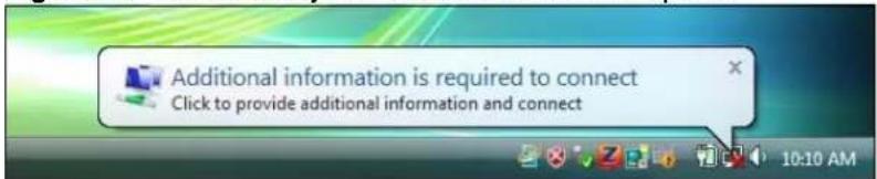
6 The Enter Credentials screen displays. Enter your User name and Password for the network to which you want to connect.
Figure 46 Vista Security: Enter Credentials
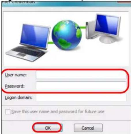
Note: If you are not sure what to enter, contact your network administrator.
7 Click OK. The Enter Credentials screen disappears and the AG-220 tries to connect to the network. The ZyXEL utility's Link Info screen displays, showing the connection status (see Section 4.2 on page 52). If the Link Info screen displays an active connection, you have successfully completed the procedure.
4.8.2 Using TLS in Vista
Take the following steps to set up WPA, WPA2 or 802.1x security using TLS in Windows Vista.
1 Either select the AP to which you want to connect in the Site Survey screen (see Section 4.3 on page 54), or configure a profile (see Section 4.4 on page 60) in the normal way.
2 In the WPA, WPA2 or 802.1x security screen, select TLS as the EAP Type. Note that the Login Name and Certificate fields are not available. You will be able to configure these soon in the Vista Security screens below.
3 Click Next.
4 In the Summary screen, click Save.
5 A message similar to the following appears in the bottom-right of your screen. Click the message.
Figure 47 Vista Security: Additional Information Required

6 The Select Certificate screen displays. Select the certificate you want to use in order to authenticate with the server, and enter your username.
Figure 48 Vista Security: Select Certificate
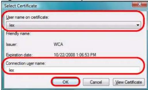
Note: If you do not have the right certificate, or are not sure which certificate you should use, contact your network administrator.
7 Click OK. The Select Certificate screen disappears and the AG-220 tries to connect to the network. The ZyXEL utility's Link Info screen displays, showing the connection status (see Section 4.2 on page 52). If the Link Info screen displays an active connection, you have successfully completed the procedure.
CHAPTER 5
Access Point Mode Configuration
This chapter shows you how to configure your AG-220 in access point mode.
Note: Access Point Mode is not available in Windows Vista.
5.1 Access Point Mode Introduction
To set your AG-220 to access point (AP) mode, select AP Mode in any utility screen (refer to Section 1.2.3 on page 25).
Access point mode allows you to set up your wireless networks without using a dedicated AP.
5.1.1 ZyXEL Utility Screen Summary
This section describes the ZyXEL utility screens when the AG-220 is in AP mode.
Figure 49 ZyXEL Utility Menu Summary: AP Mode

The following table describes the menus.
Table 17 ZyXEL Utility Menu Summary: AP Mode
| TAB DESCRIPTION | |
| AP Mode | |
| Link Info Use this screen to see your current connection status, configuration and data rate statistics. | |
| Configuration Use this screen to configure wireless LAN settings. | |
| Advanced Use this screen to change the wireless network mode. | |
| MAC Filter Use this screen to configure which computer(s) you want access to the wireless LAN through the AG-220. | |
5.1.2 Additional Setup Requirements
To bridge your wired and wireless network using the AG-220, the following requirements must be met:
1 The AG-220 must be installed on a computer connected to the wired network.
2 Either bridge the two interfaces (wireless and wired) on the computer (using the Configuration screen of the ZyXEL utility in Windows XP) or configure network sharing (refer to Appendix B on page 89 for an example).
3 Set the wireless station's IP address to be dynamic if you want the wireless stations to access the wired network or the Internet through the AG-220. Refer to Appendix E on page 121 for how to configure your computer's IP address.
5.2 The Link Info Screen
Select the AP Mode check box and wait for about five seconds to display the screen as shown.
Figure 50 Access Point Mode: Link Info
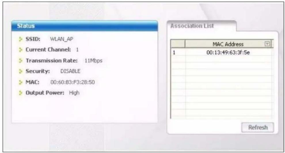
The following table describes the labels in this screen.
Table 18 Access Point Mode: Link Info
| LABEL DESCRIPTION | |
| Status | |
| SSID This field displays the name that identifies your AG-220 in the wireless LAN network. | |
| Current Channel This field displays the radio channel the AG-220 is currently using. | |
| Transmission Rate | This field displays the current transmission rate of the AG-220 in megabits per second (Mbps). |
| Security | This field shows whether data encryption is activated (WEP) or inactive (DISABLE). |
| MAC This field displays the MAC address of the AG-220. | |
| Output Power This field shows the strength of the AG-220's antenna gain or transmission power. | |
| Association List | This table lists up to 16 wireless clients that are currently connected to the AG-220. |
 | denotes a wireless client without WEP security. |
 | denotes a wireless client with WEP security enabled. |
| MAC Address | This field displays the MAC addresses of a wireless client that is currently connected to the AG-220. |
| Refresh Click Refresh to update this screen. | |
5.3 The Configuration Screen
Click Configuration in the ZyXEL utility screen to display the screen as shown.
Figure 51 Access Point Mode: Configuration
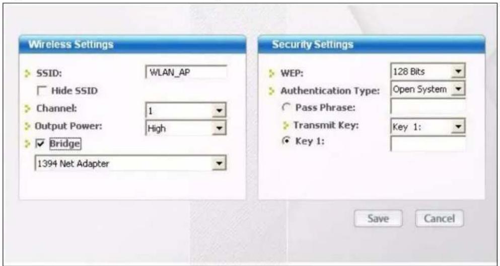
The following table describes the labels in this screen.
Table 19 Access Point Mode: Configuration
| LABEL DESCRIPTION | |
| Wireless Settings | |
| SSID The SSID identifies the wireless network to which a wireless station is associated.Wireless stations associating to the access point (the AG-220) must have the same SSID.Enter a descriptive name (up to 32 printable 7-bit ASCII characters) for the wireless LAN. | |
| Hide SSID Select this check box to hide the SSID so an intruder cannot obtain the SSID through scanning using a site survey tool. | |
| Channel Set the operating frequency/channel depending on your geographical region. | |
| Output Power | Set this field if you need to conserve power consumption (especially for notebook computers). This control changes the strength of the AG-220's antenna gain or transmission power. Antenna gain, measured in dBm (decibel relative units compared to milliwatts), is the increase in coverage. Higher antenna gain improves the range of the signal for better communications.Select High to set the AG-220's antenna to transmit at 17-dBm.Select Medium-High to set the AG-220's antenna to transmit at 15-dBm.Select Medium-Low to set the AG-220's antenna to transmit at 13-dBm.Select Low to set the AG-220's antenna to transmit at 11-dBm. This allows for the least power consumption. |
| Bridge Select the check box and an Ethernet adapter (network interface card (NIC)) on your computer from the drop-down list box. This allows you to connect your wireless network to the specified wired network. | |
| Security Settings | |
| WEP | Select 64 Bits, 128 Bits or 256 Bits to activate WEP encryption and then fill in the related fields.Select Disable to deactivate the WEP encryption. |
| Authentication Type | Select an authentication method. Choices are Auto, Shared Key and Open System.-Refer to Section 3.2.3.1.2 on page 39 for more information. |
| Pass Phrase When | you select the radio button, enter a passphrase of up to 63 case-sensitive printable characters. As you enter the passphrase, the AG-220 automatically generates four different WEP key and displays it in the key field below. Refer to Section 3.2.3.1 on page 39 for more information.At the time of writing, you cannot use passphrase to generate 256-bit WEP keys. |
| Transmit Key | Select a default WEP key to use for data encryption. The key displays in the field below. |
| Key x (where x is a number between 1 and 4) | Select this option if you want to manually enter the WEP keys.Enter the WEP key in the field provided.If you select64 Bitsin theWEPfield.Enter either 10 hexadecimal digits in the range of “A-F”, “a-f” and “0-9” (for example, 11AA22BB33) for HEX key typeorEnter 5 ASCII characters (case sensitive) ranging from “a-z”, “A-Z” and “0-9” (for example, MyKey) for ASCII key type.If you select128 Bitsin theWEPfield,Enter either 26 hexadecimal digits in the range of “A-F”, “a-f” and “0-9” (for example, 00112233445566778899AABBCC) for HEX key typeorEnter 13 ASCII characters (case sensitive) ranging from “a-z”, “A-Z” and “0-9” (for example, MyKey12345678) for ASCII key type.If you select256 Bitsin theWEPfield,Enter either 58 hexadecimal digits in the range of “A-F”, “a-f” and “0-9” (for example, 0000111122223333444455556666777788889999AAAABBBBBCCCC000011) for HEX key typeorEnter 29 ASCII characters (case sensitive) ranging from “a-z”, “A-Z” and “0-9” (for example, MyKey111122223333444455556678) for ASCII key type.Note:The values for the WEP keys must be set up exactly the same on all wireless devices in the same wireless LAN.ASCII WEP keys are case sensitive. |
| Save ClickSaveto | save the changes. |
| Cancel ClickCancel | to discard the changes. |
5.4 The Advanced Screen
To set the network mode of the AG-220, click the Advanced tab.
Figure 52 Access Point Mode: Advanced
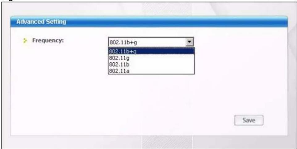
The following table describes the labels in this screen.
Table 20 Access Point Mode: Advanced
| LABEL DESCRIPTION | |
| Advanced Setting | |
| Frequency | Choose a network mode. Select 802.11b+g to have your AG-220 connect to other wireless devices in either IEEE 802.11 b or 802.11g modes. Alternatively, select 802.11g, 802.11b or 802.11a to have your AG-220 connect to other wireless devices in b, g or a mode only. |
| Save | Click Save to save the changes to the AG-220. If you are connected to a wireless network when changing network modes, the AG-220 will disconnect and then attempt to reestablish the connection using the new setting. |
5.5 The MAC Filter Screen
The MAC Filter screen allows you to configure the AG-220 to give exclusive access to devices (Accept) or exclude devices from connecting to the AG-220 (Reject). The MAC address is assigned at the factory and consists of six pairs of hexadecimal characters, for example, 00:A0:C5:00:00:02. You need to know the MAC address of the device(s) to configure this screen. See Section 3.2.2 on page 38 for more information.
Figure 53 Access Point Mode: MAC Filter
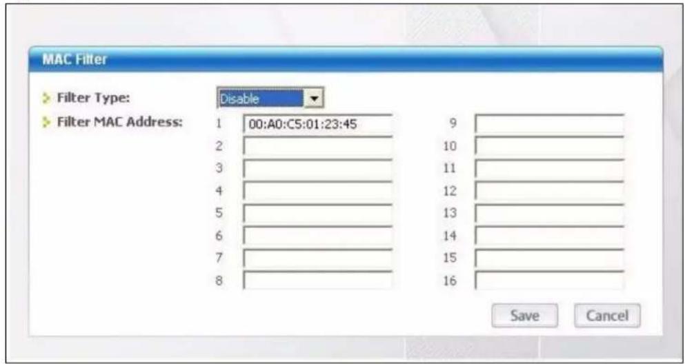
The following table describes the labels in this screen.
Table 21 Access Point Mode: MAC Filter
| LABEL DESCRIPTION | |
| Filter Type Define the filter action for the list of MAC addresses in the MAC address filter table.Select Disable to deactivate the MAC filter feature.Select Reject to block access to the AG-220, MAC addresses not listed will be allowed to access the AG-220.Select Accept to permit access to the AG-220, MAC addresses not listed will be denied access to the AG-220. | |
| Filter MAC Address 1-16 | Specify the MAC address(es) of the wireless station(s) that is allowed or denied association to the AG-220.Enter six pairs of hexadecimal digits (separated by colons) in the range of “A-F”, “a-f” and “0-9” (for example, 00:A0:C5:00:00:02).If you enter an invalid MAC address, once you click Save to save the values, a warning screen will be displayed. |
| Save Click Save to save the changes to the AG-220. | |
| Cancel Click Cancel to discard the changes. | |
CHAPTER 6 Maintenance
This chapter describes how to uninstall or upgrade the ZyXEL utility.
6.1 The About Screen
The About screen displays driver and utility version numbers of the AG-220. To display the screen as shown below, click the about ( ) button.
Figure 54 About
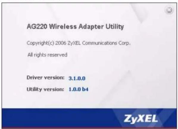
The following table describes the read-only fields in this screen.
Table 22 About
| LABEL DESCRIPTION | |
| Driver Version This field displays the version number of the AG-220 driver. | |
| Utility Version This field displays the version number of the ZyXEL utility. | |
6.2 Uninstalling the ZyXEL Utility
6.2.1 Windows XP
Follow the steps below to remove (or uninstall) the ZyXEL utility from your Windows XP computer.
1 Click Start, (All) Programs, ZyXEL AG-220 Wireless USB Adapter Utility, Uninstall ZyXEL AG-220 Wireless USB Adapter Utility.
2 When prompted, click OK or Yes to remove the driver and the utility software.
Figure 55 Uninstall: Confirm

3 Click Finish to complete uninstalling the software and restart the computer when prompted.
Figure 56 Uninstall: Finish
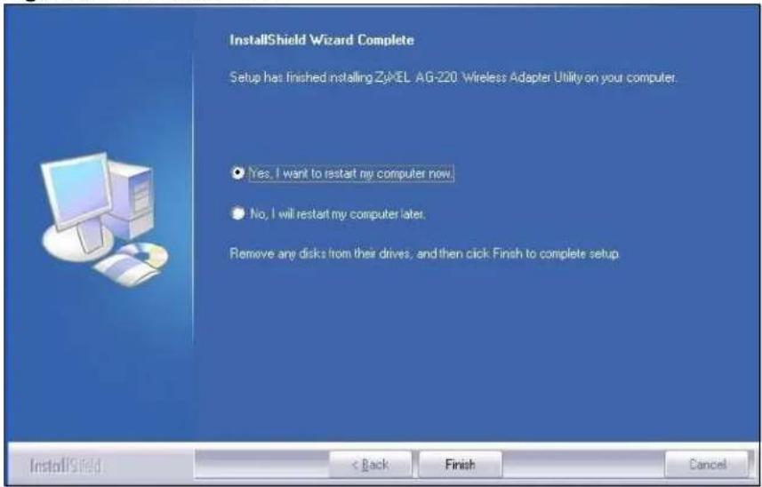
6.2.2 Windows Vista
Follow the steps below to remove (or uninstall) the ZyXEL utility from your Windows Vista computer.
1 Click the Start icon on the Windows Vista taskbar.
Figure 57 Uninstall: Start
2 In the menu that displays click Control Panel.
Figure 58 Uninstall: Control Panel
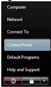
3 On the Control Panel screen click Uninstall a program.
Figure 59 Uninstall: Control Panel
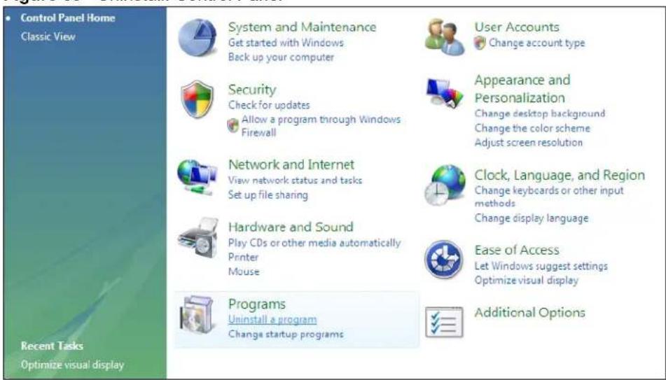
4 On the Uninstall Program screen double click ZyXEL AG-220 Wireless USB Adapter Utility. You may need to scroll down to find this if you have many programs installed.
Figure 60 Uninstall: Control Panel

5 Windows Vista will ask for your permission to uninstall the program.
6 If you give Windows Vista your permission to uninstall the ZyXEL utility the following screen will display. Click Yes to uninstall the ZyXEL utility.
Figure 61 Uninstall: Remove Utility
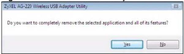
7 After the program uninstalls the following screen will display. Select whether to restart your computer now or later and click Finish.
Figure 62 Uninstall: Finish
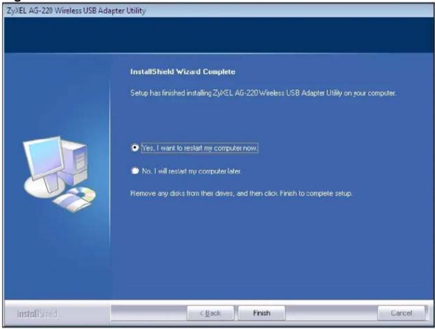
6.3 Upgrading the ZyXEL Utility
Note: Before you uninstall the ZyXEL utility, take note of your current wireless configurations.
To perform the upgrade, follow the steps below.
1 Download the latest version of the utility from the ZyXEL web site and save the file on your computer.
2 Follow the steps in Section 6.2 on page 81 to remove the current ZyXEL utility from your computer.
3 Restart your computer when prompted.
4 Disconnect the AG-220 from your computer.
5 Double-click on the setup program for the new utility to start the ZyXEL utility installation.
6 Insert the AG-220 and check the version numbers in the About screen to make sure the new utility is installed properly.
CHAPTER 7
Troubleshooting
This chapter covers potential problems and the possible remedies. After each problem description, some instructions are provided to help you to diagnose and to solve the problem.
7.1 Problems Starting the ZyXEL Utility
Table 23 Troubleshooting Starting ZyXEL Utility
| PROBLEM CORRECTIVE ACTION | |
| Cannot start the ZyXEL Wireless LAN utility | Make sure the AG-220 is properly inserted and the LED is on. Refer to the Quick Start Guide for the LED descriptions.Use theDevice Managerto check for possible hardware conflicts. ClickStart, Settings, Control Panel, System, HardwareandDevice Manager. Verify the status of the AG-220 underNetwork Adapter.(Steps may vary depending on the version of Windows).Install the AG-220 in another computer.If the error persists, you may have a hardware problem. In this case, you should contact your local vendor. |
| The ZyXEL utility icon does not display. | If you have installed the Funk Odyssey Client software on the computer, uninstall (remove) both the Funk Odyssey Client software and ZyXEL utility, and then install the ZyXEL utility again after restarting the computer. |
7.2 Problem Connecting to an Access Point
Table 24 Troubleshooting Access Point Connection Problem
| PROBLEM CORRECTIVE ACTION | |
| When using the Windows XP configuration tool, the AG-220 cannot scan for or connect to any access points. | The AG-220 might still be operating in access point mode. This results when you set the AG-220 to operate in access point mode using the ZyXEL utility, close the ZyXEL utility and then use the Windows XP configuration tool.Before you use the Windows XP configuration tool, make sure you set the AG-220 to operate in station mode before you close and exit the ZyXEL utility. |
7.3 Problem with the Link Quality
Table 25 Troubleshooting Link Quality
| PROBLEM CORRECTIVE ACTION | |
| The link quality and/or signal strength is poor all the time. | Search and connect to another AP with a better link quality using the Site Survey screen.Move your computer closer to the AP or the peer computer(s) within the transmission range.There may be too much radio interference (for example microwave or another AP using the same channel) around your wireless network. Lower the output power of each AP.Make sure there are not too many wireless stations connected to a wireless network. |
7.4 Problems Communicating With Other Computers
Table 26 Troubleshooting Communication Problems
| PROBLEM CORRECTIVE ACTION | |
| In wireless station mode, the computer with the AG-220 installed cannot communicate with the other computer(s). | In Infrastructure ModeMake sure that the AP and the associated computers are turned on and working properly.Make sure the AG-220 computer and the associated AP use the same SSID.Change the AP and the associated wireless clients to use another radio channel if interference is high.Make sure that the computer and the AP share the same security option and key. Verify the settings in theProfile Security Settingscreen.If you are using WPA(2) or WPA(2)-PSK security, try changing your encryption type from TKIP to AES or vice versa.In Ad-Hoc (IBSS) ModeVerify that the peer computer(s) is turned on.Make sure the AG-220 computer and the peer computer(s) are using the same SSID and channel.Make sure that the computer and the peer computer(s) share the same security settings.Change the wireless clients to use another radio channel if interference is high. |
| In access point mode, the wireless station(s) cannot associate to the AG-220. | Verify that the computer with the AG-220 installed is turned on.Make sure the wireless station(s) uses the same SSID as the AG-220.Make sure the wireless station(s) uses the same security settings.Verify that the wireless station(s) is not blocked in theMAC Filterscreen. |
APPENDIX A
Product Specifications
Table 27 Product Specifications
| PHYSICAL AND ENVIRONMENTAL | |
| Product Name ZyXEL AG-220 802.11a/g Wireless USB Adapter | |
| Interface USB 2.0 compatible | |
| Standards IEEE 802.11a | IEEE 802.11bIEEE 802.11g |
| Network Architectures InfrastructureAd-Hoc | |
| Operating Temperature 0 ~ 50 degrees Centigrade | |
| Storage Temperature -30 ~ 60 degrees Centigrade | |
| Operating Humidity 20 ~ 95% (non-condensing) | |
| Storage Humidity 20 ~ 95% (non-condensing) | |
| Power TX power consumption: < 380mARX power consumption: < 200mA | |
| Voltage | 5V |
| Weight 25.8 g | |
| Dimension | (W) 95 mm × (D) 30 mm × (H) 16 mm |
| RADIO SPECIFICATIONS | |
| Media Access Protocol | IEEE 802.11 |
| Frequency | Industrial Scientific Medical Band2.412 ~ 2.484 GHz (IEEE 802.11b/g) and 5.180 ~ 5.825GHz (IEEE 802.11a) |
| Operating Frequencies and Channels | IEEE 802.11b/g:2.412 ~ 2.484 GHzFCC: 11 channelsTaiwan: 11 channelsCE: 13 channelsIEEE 802.11a 5.180 ~ 5.825 GHz:5.180 ~ 5.240 GHzFCC: 4 channelsCE: 4 channels5.260 ~ 5.320 GHzFCC: 4 channelsTaiwan: 4 channelsCE: 4 channels5.500 ~ 5.700 GHzCE: 11 channels5.745 ~ 5.825 GHzFCC: 5 channelsTaiwan: 5 channels |
| Data Rate 11g: 54 Mbps with automatic fallback to 48, 36, 24, 18, 12, 9 and 6 Mbps11b: 11 Mbps with automatic fallback to 11, 5.5, 2 and 1 Mbps | |
| Modulation IEEE 802.11a: 54, 48 | 36, 24, 18, 12, 9, 6 Mbps (OFDM)IEEE 802.11b: 11, 5.5 Mbps (CCK), 2 Mbps (DQPSK), 1 Mbps (DBPSK)IEEE 802.11g: 54, 48, 36, 24, 18, 12, 9, 6 Mbps (OFDM) |
| Average Output Power IEEE 802 | 11a: 12dBm (+/- 2dBm) at 54Mbps, OFDMIEEE 802.11b: 17dBm (+/- 2dBm) at 11Mbps, CCK, QPSK, BPSPKIEEE 802.11g: 14dBm (+/- 2dBm) at 54Mbps, OFDM |
| RX Sensitivity IEEE 802.11g (OFDM): 54 Mbps: < -70 dBmIEEE 802.11b (CCK): 11 Mbps: < -85 dBm | |
| SOFTWARE SPECIFICATIONS | |
| Device Drivers Microsoft Windows | 98 Second Edition, Windows ME, Windows 2000,Windows XP, Windows XP 64-bit edition, Windows Vista |
| Security 64/128/256-bit WEP | WPA/WPA-PSK/WPA2/WPA2-PSKIEEE 802.1xWPS (Windows Vista only) |
| Roaming IEEE 802.11a/b/g compliant | |
APPENDIX B
Access Point Mode Setup Example
This example uses the network sharing feature in Windows 2000 to bridge the wired and wireless network when you set the AG-220 in access point (AP) mode.
Refer to Chapter 5 on page 73 for setup methods and requirements.
Steps may vary depending on your Windows version. You may need to install additional software in Windows 98 Second Edition and Windows ME.
Configuring the Computer on Which You Install the AG-220
1 Refer to Section 1.2.3 on page 25 to set the AG-220 to operate in AP mode.
2 Click Start, Settings, Network and Dial-up Connections (or click Start, Settings, Control Panel and double-click Network and Dial-up Connections).
Figure 63 Windows 2000: Start
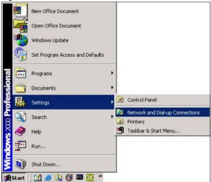
3 Right-click on the icon for your wired Ethernet adapter and click Properties.
Figure 64 Windows 2000: Network and Dial-up Connections
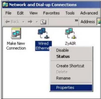
4 A Properties screen displays. Click the Sharing tab and select Enable Internet Connection Sharing for this connection. Click OK.
Figure 65 Windows 2000: Network Properties
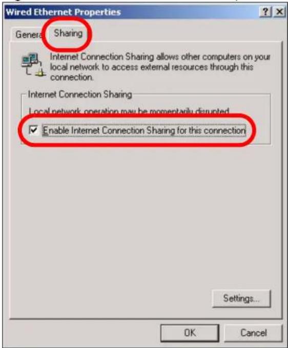
If there is more than one network adapter on the computer, select Enable Internet Connection Sharing for this connection and select the network adapter to which you want to share network access.
Figure 66 Windows 2000: Network Properties: Select Network Adapter
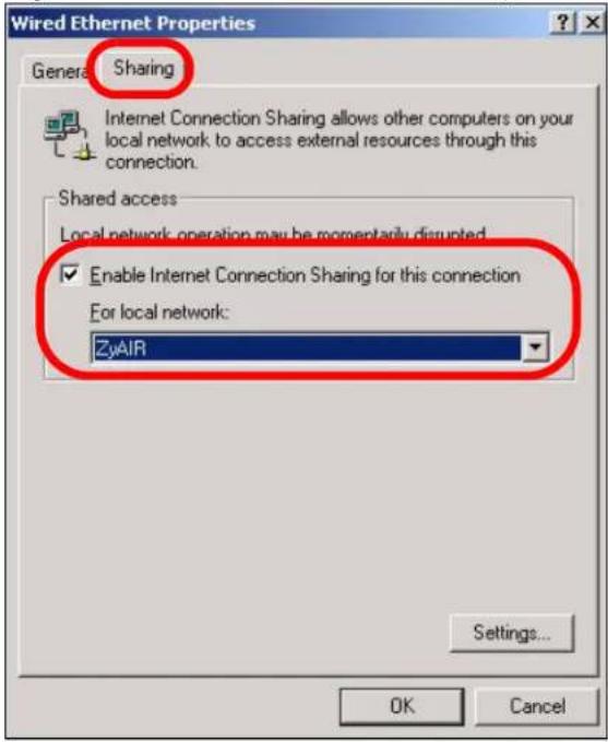
5 A notice screen displays. Click Yes.
Figure 67 Windows 2000: Local Network
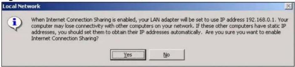
Configuring the Wireless Station Computer
Refer to Appendix E on page 121 for information on how to set up the IP address of a computer you want to connect wirelessly to the AG-220.
APPENDIX C
Windows Wireless Management
This appendix shows you how to manage your AG-220 using the Windows Vista and Windows XP wireless configuration tools.
Windows Vista
Take the following steps to connect to a wireless network using the Windows Vista wireless configuration tool (WLAN AutoConfig).
Connecting to a Wireless Network
1 In the Windows Vista taskbar, click Start ( ) > Connect To.
Figure 68 Vista: Start Menu
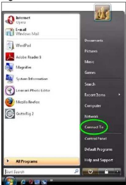
The Connect To window displays, showing all available networks.
Figure 69 Vista: The Connect To Window
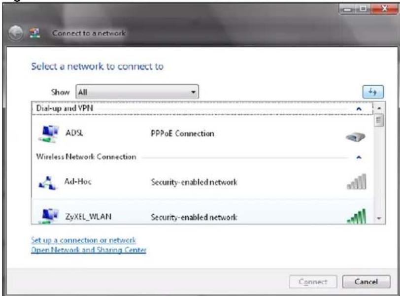
The security status of each wireless network displays, as well as an indication of its signal strength. If you use the mouse pointer to hover over a network's entry, additional information about the network displays.
Figure 70 Vista: Additional Information
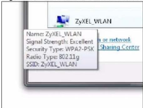
2 Double-click the network's name to join the network, or select a network and click Connect.
? If the network to which you want to connect does not display, see the section on setting up a connection manually on page 96.
3 If security is enabled, you may be prompted to enter your security key.
Figure 71 Vista: Enter Security Key
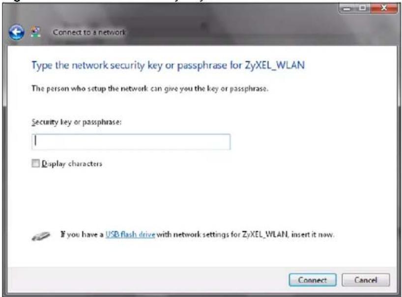
Your computer tries to connect to the wireless network.
Figure 72 Vista: Connecting
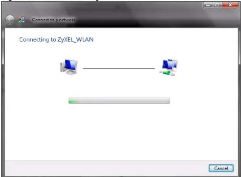
If your computer has connected to the wireless network successfully, the following screen displays.
Figure 73 Vista: Successful Connection
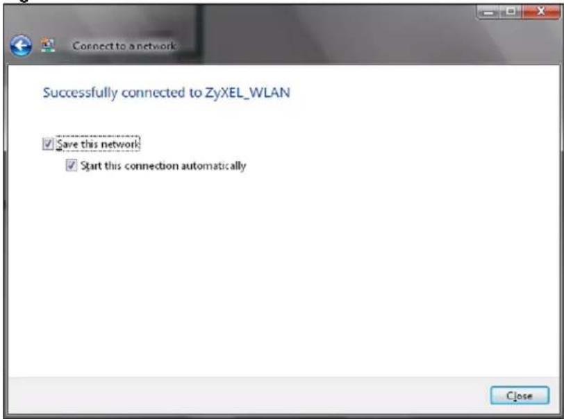
4 If you will use this network again, ensure that Save this network is selected. If you save the network, you do not have to configure its settings again.
5 Select Start this connection automatically if you want Windows to always try to use this network when you start up your computer. If you do not select this (but select Save this network) you can connect manually each time by clicking Start > Connect to and selecting the network's name from the list.
Connecting to a Network Manually
If the wireless network to which you want to connect does not appear in the Connect to window (if your network's SSID is hidden, for example), take the following steps to configure your network connection manually
1 Click Set up a connection or network at the bottom of the Connect to screen. The following screen displays.
Figure 74 Vista: Choose a Connection Option
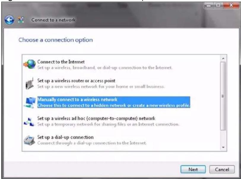
2 Click Manually connect to a wireless network. The following screen displays.
Figure 75 Vista: Connect Manually
![Manually connect to a wireless network Enter information for the wireless network you want to add Network name: Security type: [Choose an option] Encryption type: Security Key/Passphrase: Display characters Start this connection automatically Connect even if the network is not broadcasting Warning: If you select this option, your computer's privacy might be at risk. Next Cancel](/content/2026/05/920863/images/6f38dc7622a4b7ff3bd13b039587b92385e84fb2c5607cc25ca25e67802b5728.jpg)
The following table describes the labels in this screen.
Table 28 Vista: Connect Manually
| LABEL DESCRIPTION | |
| Network name Enter your | network's SSID (Service Set Identifier). |
| Security type Select the type of security used by the network to which you want to connect. The types of available security shown depend on your computer's wireless client.In this field, WPA(2)-Personal is the same as WPA(2)-PSK, and WPA(2)-Enterprise is the same as WPA(2) | |
Table 28 Vista: Connect Manually
| LABEL DESCRIPTION | |
| Encryption type Select the | type of encryption used by the network.When you use WEP or 802.1x, WEP displays.When you use a WPA mode (WPA(2)-Personal or WPA(2)-Enterprise) you can choose AES or TKIP (if supported by your computer's wireless client). |
| Security Key / Passphrase | If your network uses WEP or WPA(2)-Personal security, enter the key here. |
| Display Characters | Select this if you do not want the security key characters to be hidden. |
| Start this connection automatically | Select this box if you always want to try to connect to this network at startup. If you leave this box unchecked, you will need to connect manually each time. |
| Connect even if the network is not broadcasting | Select this box if you always want to try to connect to this network at startup, even if the network is not broadcasting its SSID. The warning in this field refers to the fact that if you do this, your computer sends out probe request packets, which contain the network's SSID and could be used by an attacker to access the network. |
| Next Click this to save your settings and move on to the next page. | |
| Cancel Click this to stop setting up your network. | |
3 When you have finished filling in the fields, click Next. the following screen displays.
Figure 76 Vista: Successfully Added Network
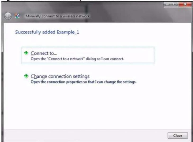
4 If you want to make any changes to the settings you just configured, click Change connection settings. Otherwise, click Connect to... In the window that displays, double-click the new network's name to connect to the network.
Setting Up An Ad-Hoc Network
Take the following steps to set up a wireless connection between two computers in Windows Vista.
1 Click Start ( ) > Connect To. In the Connect to screen, click Set up a connection or network. The following screen displays.
Figure 77 Vista: Set Up An Ad-hoc Network
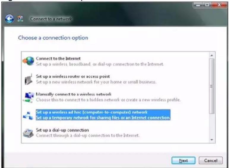
2 Select Set up a wireless ad hoc (computer-to-computer) network and click Next. The following screen displays.
Figure 78 Vista: Ad-hoc Options
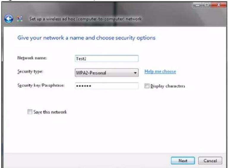
3 Enter the Network name (SSID) you want to use for your network. Select a Security type. If you are not sure what kind of security you want to use, click the Help me choose link.
? Make sure all the wireless clients on your ad-hoc network can support the type of security you select.
4 Enter the Security key/Passphrase. Everybody on the network must enter this key in their computer's wireless client in order to access the network. If you want to see the characters you entered, select the Display characters box. Otherwise, leave it empty (dots display instead of the characters).
5 If you will use this ad-hoc network again, select the Save this network box. If you do this, the next time you click Start > Connect to, you can select the network from the list.
6 Click Next. The following screen displays.
Figure 79 Vista: Ad-hoc Network Ready
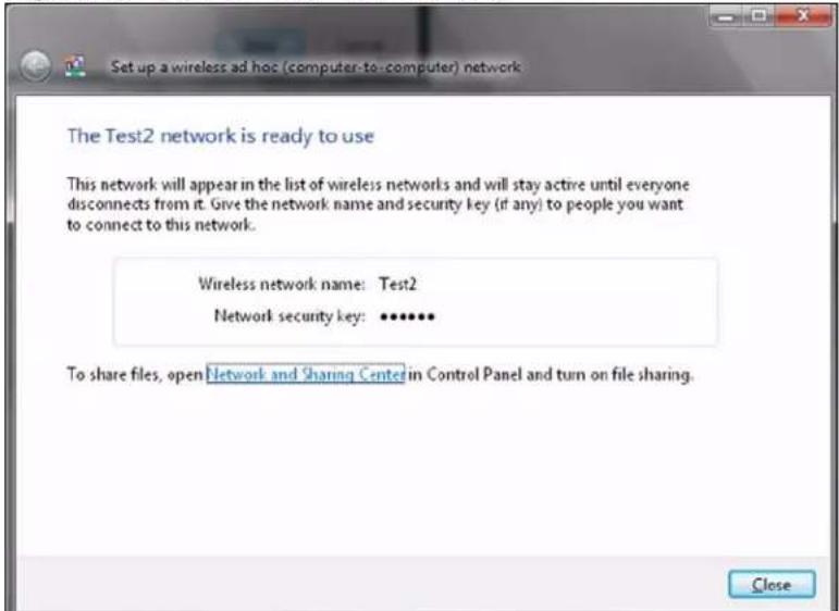
7 If you want to share files with other computers on the ad-hoc network, or let other computers use your Internet connection, click the Network and Sharing Center link. Otherwise, click Close.
Windows XP
Be sure you have the Windows XP service pack 2 installed on your computer. Otherwise, you should at least have the Windows XP service pack 1 already on your computer and download the support patch for WPA from the Microsoft web site.
Windows XP SP2 screen shots are shown unless otherwise specified. Click the help icon ( ? ) in most screens, move the cursor to the item that you want the information about and click to view the help.
Activating Wireless Zero Configuration
1 Click Start, Control Panel and double-click Network Connections.
2 Double-click on the icon for wireless network connection.
3 The status window displays as shown below. Click Properties.
Figure 80 Windows XP SP1: Wireless Network Connection Status
Figure 81 Windows XP SP2: Wireless Network Connection Status
4 The Wireless Network Connection Properties screen displays. Click the Wireless Networks tab. Make sure the Use Windows to configure my wireless network settings check box is selected.
Figure 82 Windows XP SP1: Wireless Network Connection Properties

Figure 83 Windows XP SP2: Wireless Network Connection Properties
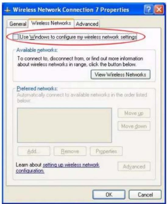
If you see the following screen, refer to article 871122 on the Microsoft web site for information on starting WZC.
Figure 84 Windows XP SP2: WZC Not Available
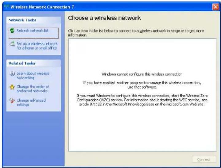
Connecting to a Wireless Network
1 Double-click the network icon for wireless connections in the system tray to open the Wireless Network Connection Status screen.
Figure 85 Windows XP SP2: System Tray Icon
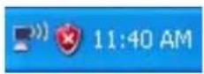
The type of the wireless network icon in Windows XP SP2 indicates the status of the AG-220. Refer to the following table for details.
Table 29 Windows XP SP2: System Tray Icon
| ICON DESCRIPTION | |
| The AG-220 is connected to a wireless network. | |
| The AG-220 is in the process of connecting to a wireless network. | |
| The connection to a wireless network is limited because the network did not assign a network address to the computer. | |
| The AG-220 is not connected to a wireless network. | |
2 Windows XP SP2: In the Wireless Network Connection Status screen, click View Wireless Networks to open the Wireless Network Connection screen.
Figure 86 Windows XP SP2: Wireless Network Connection Status
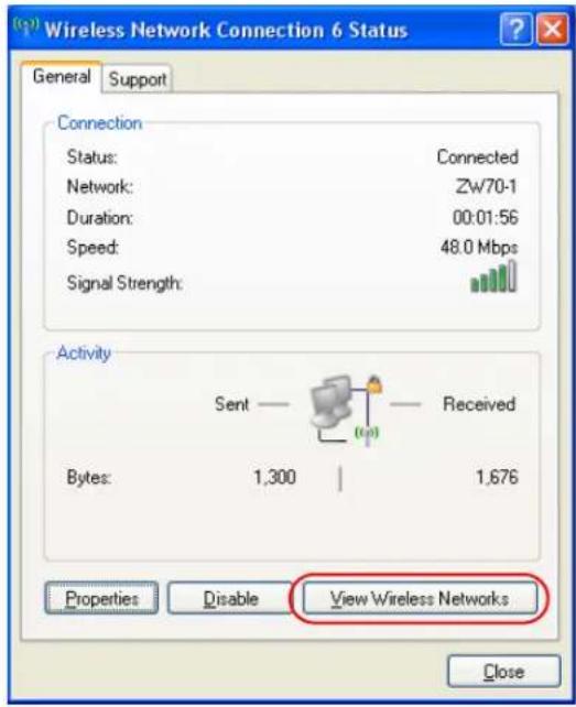
Windows XP SP1: In the Wireless Network Connection Status screen, click Properties and the Wireless Networks tab to open the Wireless Network Connection Properties screen.
Figure 87 Windows XP SP1: Wireless Network Connection Status
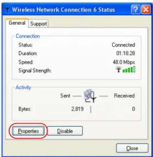
3 Windows XP SP2: Click Refresh network list to reload and search for available wireless devices within transmission range. Select a wireless network in the list and click Connect to join the selected wireless network.
Figure 88 Windows XP SP2: Wireless Network Connection
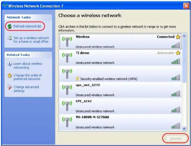
The following table describes the icons in the wireless network list.
Table 30 Windows XP SP2: Wireless Network Connection
| ICON DESCRIPTION | |
 | This denotes that wireless security is activated for the wireless network. |
| [27VW] | This denotes that this wireless network is your preferred network. Ordering your preferred networks is important because the AG-220 tries to associate to the preferred network first in the order that you specify. Refer to the section on ordering the preferred networks for detailed information. |
 | This denotes the signal strength of the wireless network.Move your cursor to the icon to see details on the signal strength. |
Windows XP SP1: Click Refresh to reload and search for available wireless devices within transmission range. Select a wireless network in the Available networks list, click Configure and set the related fields to the same security settings as the associated AP to add the selected network into the Preferred networks table. Click OK to join the selected wireless network. Refer to the section on security settings (discussed later) for more information.
Figure 89 Windows XP SP1: Wireless Network Connection Properties
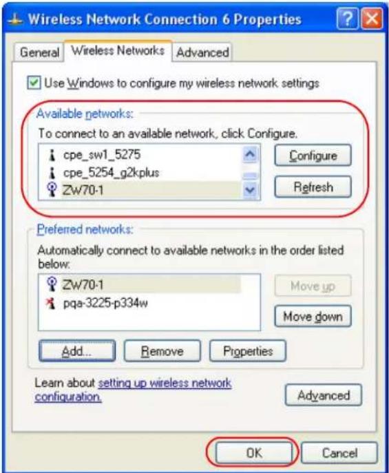
- Windows XP SP2: If the wireless security is activated for the selected wireless network, the Wireless Network Connection screen displays. You must set the related fields in the Wireless Network Connection screen to the same security settings as the associated AP and click Connect. Refer to the section about security settings for more information. Otherwise click Cancel and connect to another wireless network without data encryption. If there is no security activated for the selected wireless network, a warning screen appears. Click Connect Anyway if wireless security is not your concern.
Figure 90 Windows XP SP2: Wireless Network Connection: WEP or WPA-PSK
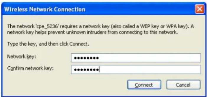
Figure 91 Windows XP SP2: Wireless Network Connection: No Security
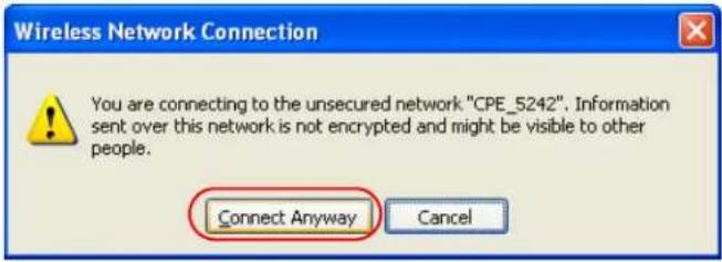
5 Verify that you have successfully connected to the selected network and check the connection status in the wireless network list or the connection icon in the Preferred networks or Available networks list.
The following table describes the connection icons.
Table 31 Windows XP: Wireless Networks
| ICON DESCRIPTION | |
| This denotes the wireless network is an available wireless network. | |
| This denotes the AG-220 is associated to the wireless network. | |
| This denotes the wireless network is not available. |
Security Settings
When you configure the AG-220 to connect to a secure network but the security settings are not yet enabled on the AG-220, you will see different screens according to the authentication and encryption methods used by the selected network.
Association
Select a network in the Preferred networks list and click Properties to view or configure security.
Figure 92 Windows XP: Wireless (network) properties: Association
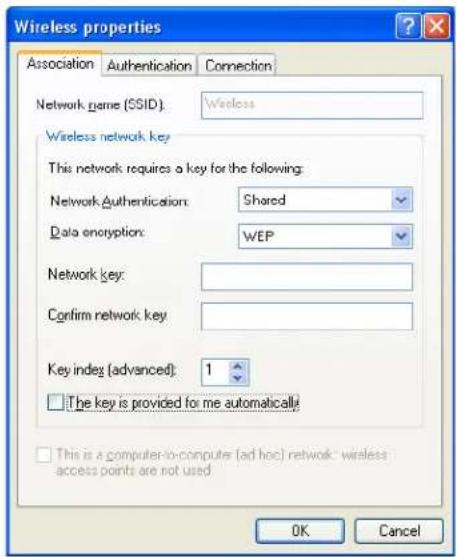
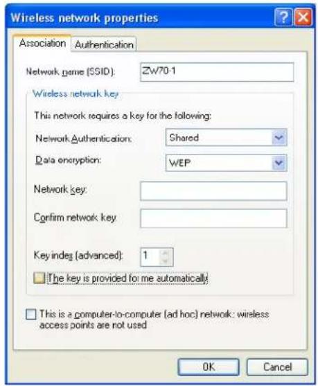
The following table describes the labels in this screen.
Table 32 Windows XP: Wireless (network) properties: Association
| LABEL DESCRIPTION | |
| Network name (SSID) | This field displays the SSID (Service Set IDentifier) of each wireless network. |
| Network Authentication | This field automatically shows the authentication method (Share, Open, WPA or WPA-PSK) used by the selected network. |
| Data Encryption | This field automatically shows the encryption type (TKIP, WEP or Disable) used by the selected network. |
| Network Key Enter the pre-shared key or WEP key.The values for the keys must be set up exactly the same on all wireless devices in the same wireless LAN. | |
| Confirm network key | Enter the key again for confirmation. |
| Key index (advanced) | Select a default WEP key to use for data encryption.This field is available only when the network use WEP encryption method and the The key is provided for me automatically check box is not selected. |
| The key is provided for me automatically | If this check box is selected, the wireless AP assigns the AG-220 a key. |
| This is a computer-to-computer (ad hoc) network; wireless access points are not used | If this check box is selected, you are connecting to another computer directly. |
| OK Click OK to save | your changes. |
| Cancel | Click Cancel to leave this screen without saving any changes you may have made. |
Authentication
Click the Authentication tab in the Wireless (network) properties screen to display the screen shown next. The fields on this screen are grayed out when the network is in Ad-Hoc mode or data encryption is disabled.
Figure 93 Windows XP: Wireless (network) properties: Authentication
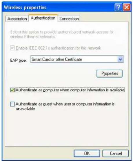
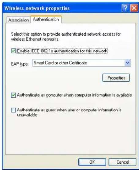
The following table describes the labels in this screen.
Table 33 Windows XP: Wireless (network) properties: Authentication
| LABEL DESCRIPTION | |
| Enable IEEE 802.1x authentication for this network | This field displays whether the IEEE 802.1x authentication is active.If the network authentication is set toOpenin the previous screen, you can choose to disable or enable this feature. |
| EAP Type | Select the type of EAP authentication. Options areProtected EAP (PEAP) andSmart Card or other Certificate. |
| Properties | Click this button to open the properties screen and configure certificates. The screen varies depending on what you select in theEAP typefield. |
| Authenticate as computer when computer information is available | Select this check box to have the computer send its information to the network for authentication when a user is not logged on. |
| Authenticate as guest when user or computer information is unavailable | Select this check box to have the computer access to the network as a guest when a user is not logged on or computer information is not available. |
| OK Click OKto save your changes. | |
| Cancel | Click Cancelto leave this screen without saving any changes you may have made. |
Authentication Properties
Select an EAP authentication type in the Wireless (network) properties: Authentication screen and click the Properties button to display the following screen.
Protected EAP Properties
Figure 94 Windows XP: Protected EAP Properties
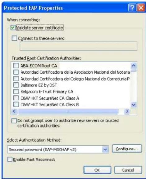
The following table describes the labels in this screen.
Table 34 Windows XP: Protected EAP Properties
| LABEL DESCRIPTION | |
| Validate server certificate | Select the check box to verify the certificate of the authentication server. |
| Connect to these servers | Select the check box and specify a domain in the field below to have your computer connect to a server which resides only within this domain. |
| Trusted Root Certification Authorities: | Select a trusted certification authority from the list below.Note: You must first have a wired connection to a network and obtain the certificate(s) from a certificate authority (CA).Consult your network administrator for more information. |
| Do not prompt user to authorize new server or trusted certification authorities. | Select this check box to verify a new authentication server or trusted CA without prompting.This field is available only if you installed the Windows XP server pack 2. |
| Select Authentication Method: | Select an authentication method from the drop-down list box and click Configure to do settings. |
| Enable Fast Reconnect | Select the check box to automatically reconnect to the network (without re-authentication) if the wireless connection goes down. |
| OK Click OK to save your changes. | |
| Cancel | Click Cancel to leave this screen without saving any changes you may have made. |
Smart Card or other Certificate Properties
Figure 95 Windows XP: Smart Card or other Certificate Properties
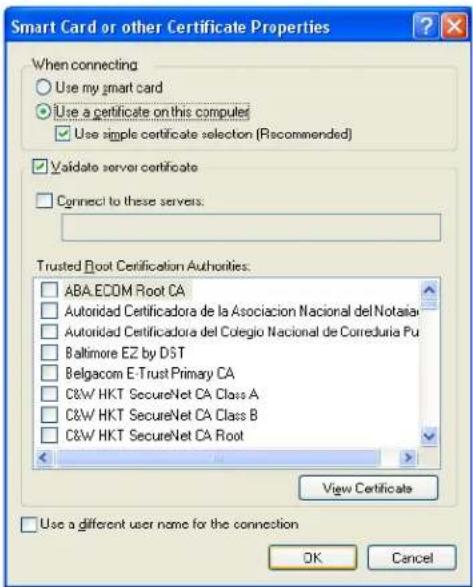
The following table describes the labels in this screen.
Table 35 Windows XP: Smart Card or other Certificate Properties
| LABEL DESCRIPTION | |
| Use my smart card | Select this check box to use the smart card for authentication. |
| Use a certificate on this computer | Select this check box to use a certificate on your computer for authentication. |
| Validate server certificate | Select the check box to check the certificate of the authentication server. |
| Connect to these servers | Select the check box and specify a domain in the field below to have your computer connect to a server which resides only within this domain. |
| Trusted Root Certification Authorities: | Select a trusted certification authority from the list below.Note: You must first have a wired connection to a network and obtain the certificate(s) from a certificate authority (CA).Consult your network administrator for more information. |
| View Certificate Click this button if you want to verify the selected certificate. | |
| Use a different user name for the connection: | Select the check box to use a different user name when the user name in the smart card or certificate is not the same as the user name in the domain that you are logged on to. |
| OK Click OK to save your changes. | |
| Cancel | Click Cancel to leave this screen without saving any changes you may have made. |
Ordering the Preferred Networks
Follow the steps below to manage your preferred networks.
1 Windows XP SP2: Click Change the order of preferred networks in the Wireless Network Connection screen (see Figure 88 on page 105). The screen displays as shown.
Figure 96 Windows XP SP2: Wireless Networks: Preferred Networks
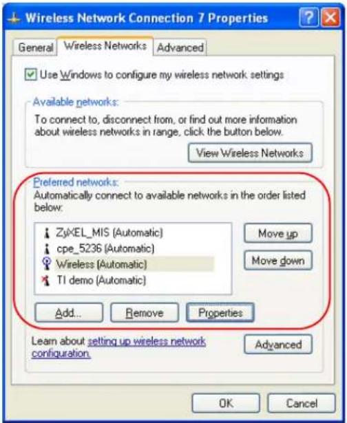
Windows XP SP1: In the Wireless Network Connection Status screen, click Properties and the Wireless Networks tab to open the screen as shown.
Figure 97 Windows XP SP1: Wireless Networks: Preferred Networks
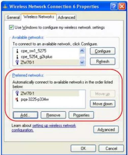
2 Whenever the AG-220 tries to connect to a new network, the new network is added in the Preferred networks table automatically. Select a network and click Move up or Move down to change it's order, click Remove to delete it or click Properties to view
the security, authentication or connection information of the selected network. Click Add to add a preferred network into the list manually.
APPENDIX D Wireless Security
Types of EAP Authentication
This section discusses some popular authentication types: EAP-MD5, EAP-TLS, EAP-TTLS, PEAP and LEAP. Your wireless LAN device may not support all authentication types.
EAP (Extensible Authentication Protocol) is an authentication protocol that runs on top of the IEEE 802.1x transport mechanism in order to support multiple types of user authentication. By using EAP to interact with an EAP-compatible RADIUS server, an access point helps a wireless station and a RADIUS server perform authentication.
The type of authentication you use depends on the RADIUS server and an intermediary AP(s) that supports IEEE 802.1x.
For EAP-TLS authentication type, you must first have a wired connection to the network and obtain the certificate(s) from a certificate authority (CA). A certificate (also called digital IDs) can be used to authenticate users and a CA issues certificates and guarantees the identity of each certificate owner.
EAP-MD5 (Message-Digest Algorithm 5)
MD5 authentication is the simplest one-way authentication method. The authentication server sends a challenge to the wireless station. The wireless station ‘proves’ that it knows the password by encrypting the password with the challenge and sends back the information. Password is not sent in plain text.
However, MD5 authentication has some weaknesses. Since the authentication server needs to get the plaintext passwords, the passwords must be stored. Thus someone other than the authentication server may access the password file. In addition, it is possible to impersonate an authentication server as MD5 authentication method does not perform mutual authentication. Finally, MD5 authentication method does not support data encryption with dynamic session key. You must configure WEP encryption keys for data encryption.
EAP-TLS (Transport Layer Security)
With EAP-TLS, digital certifications are needed by both the server and the wireless stations for mutual authentication. The server presents a certificate to the client. After validating the identity of the server, the client sends a different certificate to the server. The exchange of certificates is done in the open before a secured tunnel is created. This makes user identity vulnerable to passive attacks. A digital certificate is an electronic ID card that authenticates the sender's identity. However, to implement EAP-TLS, you need a Certificate Authority (CA) to handle certificates, which imposes a management overhead.
EAP-TTLS (Tunneled Transport Layer Service)
EAP-TTLS is an extension of the EAP-TLS authentication that uses certificates for only the server-side authentications to establish a secure connection. Client authentication is then done by sending username and password through the secure connection, thus client identity is protected. For client authentication, EAP-TTLS supports EAP methods and legacy authentication methods such as PAP, CHAP, MS-CHAP and MS-CHAP v2.
PEAP (Protected EAP)
Like EAP-TTLS, server-side certificate authentication is used to establish a secure connection, then use simple username and password methods through the secured connection to authenticate the clients, thus hiding client identity. However, PEAP only supports EAP methods, such as EAP-MD5, EAP-MSCHAPv2 and EAP-GTC (EAP-Generic Token Card), for client authentication. EAP-GTC is implemented only by Cisco.
LEAP
LEAP (Lightweight Extensible Authentication Protocol) is a Cisco implementation of IEEE 802.1x.
Dynamic WEP Key Exchange
The AP maps a unique key that is generated with the RADIUS server. This key expires when the wireless connection times out, disconnects or reauthentication times out. A new WEP key is generated each time reauthentication is performed.
If this feature is enabled, it is not necessary to configure a default encryption key in the Wireless screen. You may still configure and store keys here, but they will not be used while Dynamic WEP is enabled.
Note: EAP-MD5 cannot be used with Dynamic WEP Key Exchange
For added security, certificate-based authentications (EAP-TLS, EAP-TTLS and PEAP) use dynamic keys for data encryption. They are often deployed in corporate environments, but for public deployment, a simple user name and password pair is more practical. The following table is a comparison of the features of authentication types.
Table 36 Comparison of EAP Authentication Types
| EAP-MD5 EAP-TLS EAP-TTLS PEAP LEAP | |||||
| Mutual Authentication No Yes | Yes Yes Yes | ||||
| Certificate – Client | No | Yes | Optional | Optional | No |
| Certificate – Server | No | Yes | Yes | Yes | No |
| Dynamic Key Exchange | No | Yes | Yes | Yes | Yes |
| Credential Integrity | None | Strong | Strong | Strong | Moderate |
| Deployment Difficulty | Easy | Hard | Moderate | Moderate | Moderate |
| Client Identity Protection | No | No | Yes | Yes | No |
WPA and WPA2
Wi-Fi Protected Access (WPA) is a subset of the IEEE 802.11i standard. WPA2 (IEEE 802.11i) is a wireless security standard that defines stronger encryption, authentication and key management than WPA.
Key differences between WPA(2) and WEP are improved data encryption and user authentication.
If both an AP and the wireless clients support WPA2 and you have an external RADIUS server, use WPA2 for stronger data encryption. If you don't have an external RADIUS server, you should use WPA2-PSK (WPA2-Pre-Shared Key) that only requires a single (identical) password entered into each access point, wireless gateway and wireless client. As long as the passwords match, a wireless client will be granted access to a WLAN.
If the AP or the wireless clients do not support WPA2, just use WPA or WPA-PSK depending on whether you have an external RADIUS server or not.
Select WEP only when the AP and/or wireless clients do not support WPA or WPA2. WEP is less secure than WPA or WPA2.
Encryption
Both WPA and WPA2 improve data encryption by using Temporal Key Integrity Protocol (TKIP), Message Integrity Check (MIC) and IEEE 802.1x. WPA and WPA2 use Advanced Encryption Standard (AES) in the Counter mode with Cipher block chaining Message authentication code Protocol (CCMP) to offer stronger encryption than TKIP.
TKIP uses 128-bit keys that are dynamically generated and distributed by the authentication server. AES (Advanced Encryption Standard) is a block cipher that uses a 256-bit mathematical algorithm called Rijndael. They both include a per-packet key mixing function, a Message Integrity Check (MIC) named Michael, an extended initialization vector (IV) with sequencing rules, and a re-keying mechanism.
WPA and WPA2 regularly change and rotate the encryption keys so that the same encryption key is never used twice.
The RADIUS server distributes a Pairwise Master Key (PMK) key to the AP that then sets up a key hierarchy and management system, using the PMK to dynamically generate unique data encryption keys to encrypt every data packet that is wirelessly communicated between the AP and the wireless stations. This all happens in the background automatically.
The Message Integrity Check (MIC) is designed to prevent an attacker from capturing data packets, altering them and resending them. The MIC provides a strong mathematical function in which the receiver and the transmitter each compute and then compare the MIC. If they do not match, it is assumed that the data has been tampered with and the packet is dropped.
By generating unique data encryption keys for every data packet and by creating an integrity checking mechanism (MIC), with TKIP and AES it is more difficult to decrypt data on a Wi-Fi network than WEP and difficult for an intruder to break into the network.
The encryption mechanisms used for WPA(2) and WPA(2)-PSK are the same. The only difference between the two is that WPA(2)-PSK uses a simple common password, instead of user-specific credentials. The common-password approach makes WPA(2)-PSK susceptible to brute-force password-guessing attacks but it's still an improvement over WEP as it employs a consistent, single, alphanumeric password to derive a PMK which is used to generate unique temporal encryption keys. This prevent all wireless devices sharing the same encryption keys. (a weakness of WEP)
User Authentication
WPA and WPA2 apply IEEE 802.1x and Extensible Authentication Protocol (EAP) to authenticate wireless stations using an external RADIUS database. WPA2 reduces the number of key exchange messages from six to four (CCMP 4-way handshake) and shortens the time required to connect to a network. Other WPA2 authentication features that are different from WPA include key caching and pre-authentication. These two features are optional and may not be supported in all wireless devices.
Key caching allows a wireless client to store the PMK it derived through a successful authentication with an AP. The wireless client uses the PMK when it tries to connect to the same AP and does not need to go with the authentication process again.
Pre-authentication enables fast roaming by allowing the wireless client (already connecting to an AP) to perform IEEE 802.1x authentication with another AP before connecting to it.
WPA(2)-PSK Application Example
A WPA(2)s-PSK application looks as follows.
1 First enter identical passwords into the AP and all wireless clients. The Pre-Shared Key (PSK) must consist of between 8 and 63 ASCII characters or 64 hexadecimal characters (including spaces and symbols).
2 The AP checks each client's password and (only) allows it to join the network if it matches its password.
3 The AP and wireless clients use the pre-shared key to generate a common PMK.
4 The AP and wireless clients use the TKIP or AES encryption process to encrypt data exchanged between them.
Figure 98 WPA-PSK Authentication
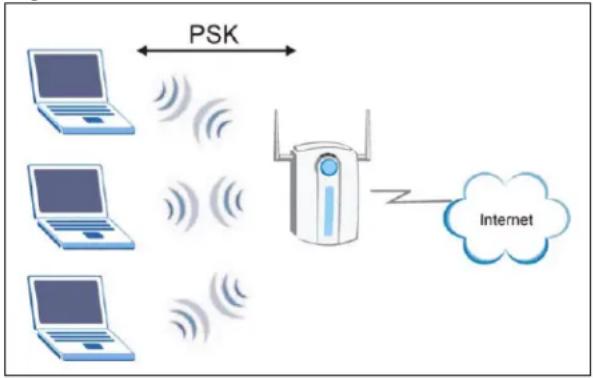
flowchart
graph TD
    A["Laptop"] <-->|PSK| B["Wi-Fi Router"]
    C["Laptop"] <-->|PSK| B
    D["Laptop"] <-->|PSK| B
    E["Laptop"] <-->|PSK| B
    B --> F["Internet"]
WPA(2) with RADIUS Application Example
You need the IP address of the RADIUS server, its port number (default is 1812), and the RADIUS shared secret. A WPA(2) application example with an external RADIUS server looks as follows. "A" is the RADIUS server. "DS" is the distribution system.
1 The AP passes the wireless client's authentication request to the RADIUS server.
2 The RADIUS server then checks the user's identification against its database and grants or denies network access accordingly.
3 The RADIUS server distributes a Pairwise Master Key (PMK) key to the AP that then sets up a key hierarchy and management system, using the pair-wise key to dynamically generate unique data encryption keys to encrypt every data packet that is wirelessly communicated between the AP and the wireless clients.
Figure 99 WPA(2) with RADIUS Application Example
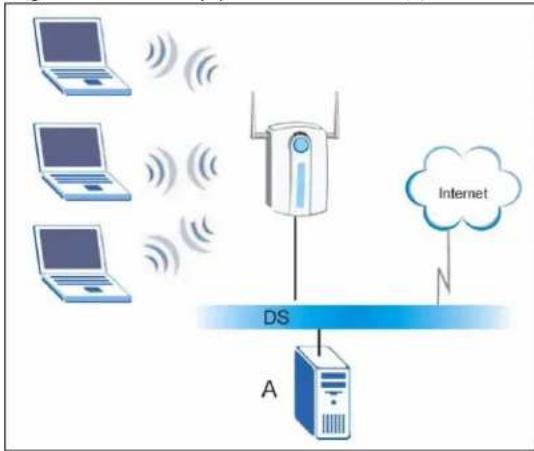
flowchart
graph TD
    A["Laptop"] -->|Wireless Signal| B["Drone"]
    C["Laptop"] -->|Wireless Signal| B
    D["Laptop"] -->|Wireless Signal| B
    B --> E["Internet"]
    E --> F["Cloud"]
    G["DS"] --> H["A"]
    H --> I["Server"]
Security Parameters Summary
Refer to this table to see what other security parameters you should configure for each Authentication Method/ key management protocol type. MAC address filters are not dependent on how you configure these security features.
Table 37 Wireless Security Relational Matrix
| AUTHENTICATION METHOD/ KEYMANAGEMENT PROTOCOL | ENCRYPTIONMETHOD | ENTERMANUAL KEY | IEEE 802.1X |
| Open None No Disable | |||
| Enable without Dynamic WEP Key | |||
| Open | WEP | No | Enable with Dynamic WEP Key |
| Yes Enable without | Dynamic WEP Key | ||
| Yes Disable | |||
| Shared | WEP | No | Enable with Dynamic WEP Key |
| Yes Enable without | Dynamic WEP Key | ||
| Yes Disable | |||
| WPA TKIP/AES No Enable | |||
| WPA-PSK TKIP/AES Yes Disable | |||
| WPA2 TKIP/AES No Enable | |||
| WPA2-PSK | TKIP/AES | Yes | Disable |
APPENDIX E
Setting up Your Computer's IP Address
All computers must have a 10M or 100M Ethernet adapter card and TCP/IP installed.
Windows 98/Mc/2000/XP/Vista and later operating systems and all versions of UNIX/LINUX include the software components you need to install and use TCP/IP on your computer. Windows 3.1 requires the purchase of a third-party TCP/IP application package.
TCP/IP should already be installed on computers using Windows 2000, XP and Vista.
After the appropriate TCP/IP components are installed, configure the TCP/IP settings in order to "communicate" with your network.
Windows 98/Me
Click Start, Settings, Control Panel and double-click the Network icon to open the Network window
Figure 100 Windows 98/Me: Network: Configuration
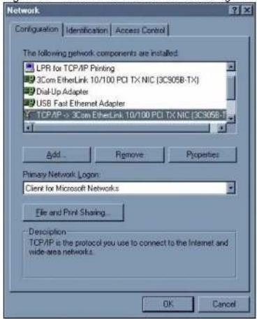
Installing Components
The Network window Configuration tab displays a list of installed components. You need a network adapter, the TCP/IP protocol and Client for Microsoft Networks.
If you need the adapter:
1 In the Network window, click Add.
2. Select Adanter and then click Add
©
Figure 102 Windows 98/Me: TCP/IP Properties: DNS Configuration
4 Click the Gateway tab.
- If you do not know your gateway's IP address, remove previously installed gateways.
- If you have a gateway IP address, type it in the New gateway field and click Add.
5 Click OK to save and close the TCP/IP Properties window.
6 Click OK to close the Network window. Insert the Windows CD if prompted.
7 Restart your computer when prompted.
Verifying Settings
1 Click Start and then Run.
2 In the Run window, type "winipcfg" and then click OK to open the IP Configuration window.
3 Select your network adapter. You should see your computer's IP address, subnet mask and default gateway.
Windows 2000/XP
1 For Windows XP, click start, Control Panel. In Windows 2000, click Start, Settings, Control Panel.
Figure 103 Windows XP: Start Menu
2 For Windows XP, click Network Connections. For Windows 2000, click Network and Dial-up Connections.
Figure 104 Windows XP: Control Panel
3 Right-click Local Area Connection and then click Properties.
Figure 105 Windows XP: Control Panel: Network Connections: Properties
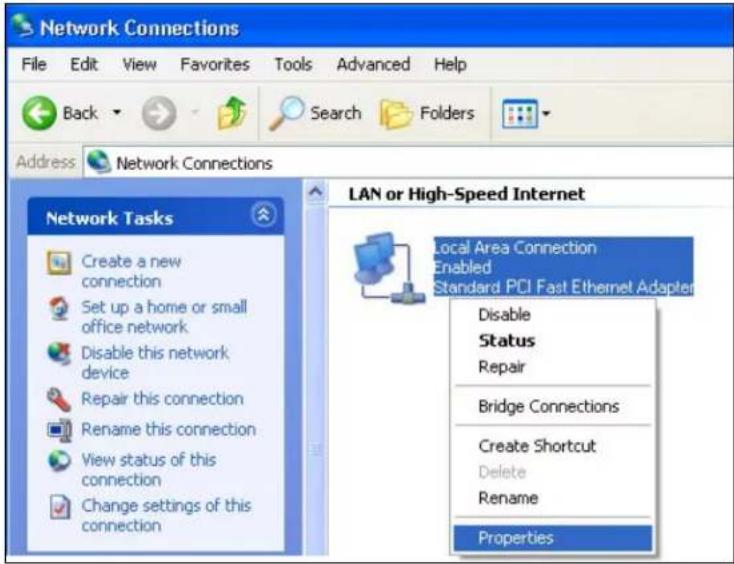
4 Select Internet Protocol (TCP/IP) (under the General tab in Win XP) and click Properties.
Figure 106 Windows XP: Local Area Connection Properties
![Local Area Connection Properties General Authentication Advanced Connect using: Accton EN1207D-TX PCI Fast Ethernet Adapter Configure... This connection uses the following items: Client for Microsoft Networks File and Printer Sharing for Microsoft Networks QoS Packet Scheduler Internet Protocol [TCP/IP] Install... Uninstall Properties Description Transmission Control Protocol/Internet Protocol. The default wide area network protocol that provides communication across diverse interconnected networks. Show icon in notification area when connected OK Cancel](/content/2026/05/920863/images/cf1fbb8c734b460c705ea0633bb7b6223a2a565689d17180ac781e1368c63e7e.jpg)
5 The Internet Protocol TCP/IP Properties window opens (the General tab in Windows XP).
- If you have a dynamic IP address click Obtain an IP address automatically.
- If you have a static IP address click Use the following IP Address and fill in the IP address, Subnet mask, and Default gateway fields. Click Advanced.
Figure 107 Windows XP: Advanced TCP/IP Settings
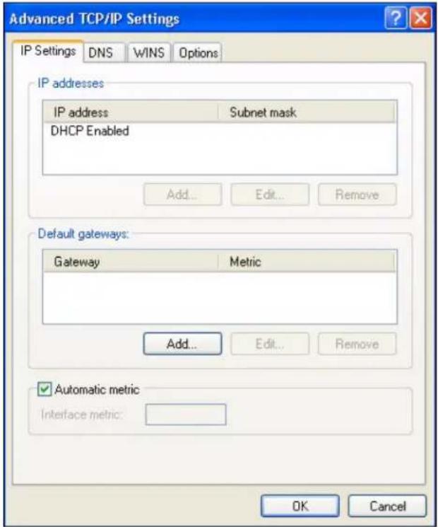
6 If you do not know your gateway's IP address, remove any previously installed gateways in the IP Settings tab and click OK.
Do one or more of the following if you want to configure additional IP addresses:
• In the IP Settings tab, in IP addresses, click Add.
- In TCP/IP Address, type an IP address in IP address and a subnet mask in Subnet mask, and then click Add.
- Repeat the above two steps for each IP address you want to add.
- Configure additional default gateways in the IP Settings tab by clicking Add in Default gateways.
- In TCP/IP Gateway Address, type the IP address of the default gateway in Gateway. To manually configure a default metric (the number of transmission hops), clear the Automatic metric check box and type a metric in Metric.
- Click Add.
- Repeat the previous three steps for each default gateway you want to add.
- Click OK when finished.
7 In the Internet Protocol TCP/IP Properties window (the General tab in Windows XP):
- Click Obtain DNS server address automatically if you do not know your DNS server IP address(es).
- If you know your DNS server IP address(es), click Use the following DNS server addresses, and type them in the Preferred DNS server and Alternate DNS server fields.
If you have previously configured DNS servers, click Advanced and then the DNS tab to order them.
Figure 108 Windows XP: Internet Protocol (TCP/IP) Properties
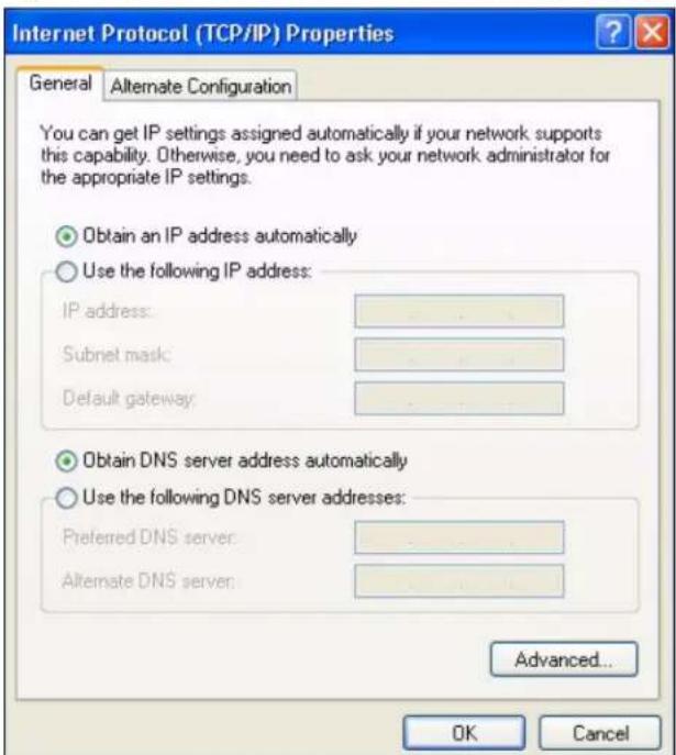
8 Click OK to close the Internet Protocol (TCP/IP) Properties window.
9 Click OK to close the Local Area Connection Properties window.
10 Restart your computer (if prompted).
Verifying Settings
1 Click Start, All Programs, Accessories and then Command Prompt.
2 In the Command Prompt window, type "ipconfig" and then press [ENTER]. You can also open Network Connections, right-click a network connection, click Status and then click the Support tab.
Windows Vista
This section shows screens from Windows Vista Enterprise Version 6.0.
1 Click the Start icon, Control Panel.
Figure 109 Windows Vista: Start Menu
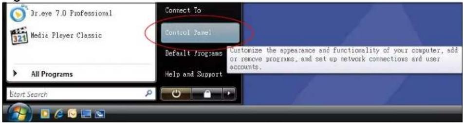
2 In the Control Panel, double-click Network and Internet.
Figure 110 Windows Vista: Control Panel
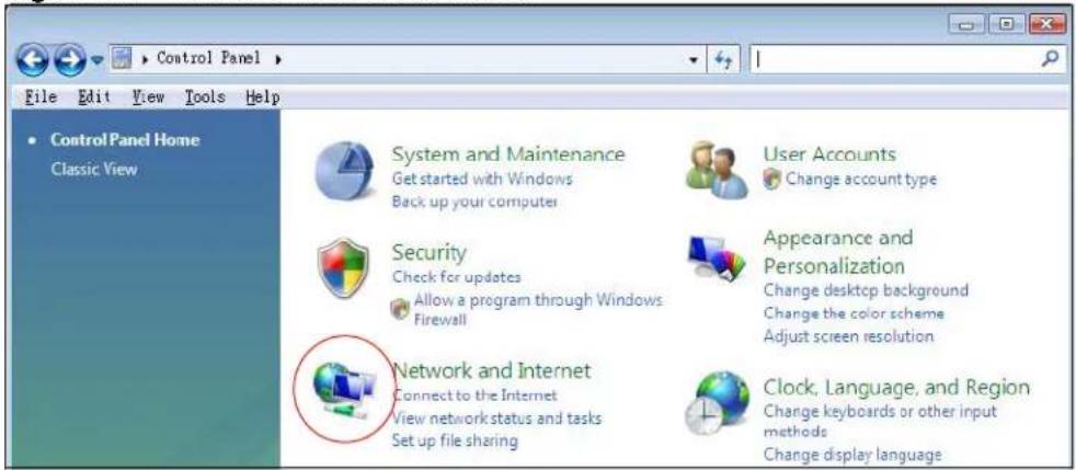
3 Click Network and Sharing Center.
Figure 111 Windows Vista: Network And Internet
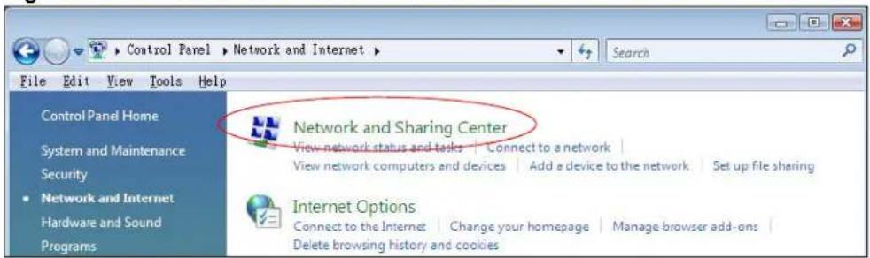
4 Click Manage network connections.
Figure 112 Windows Vista: Network and Sharing Center
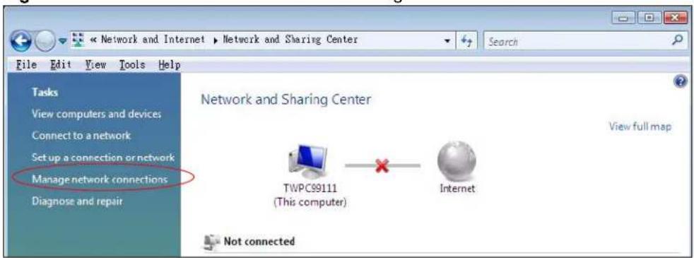
5 Right-click Local Area Connection and then click Properties.
? During this procedure, click Continue whenever Windows displays a screen saying that it needs your permission to continue.
Figure 113 Windows Vista: Network and Sharing Center
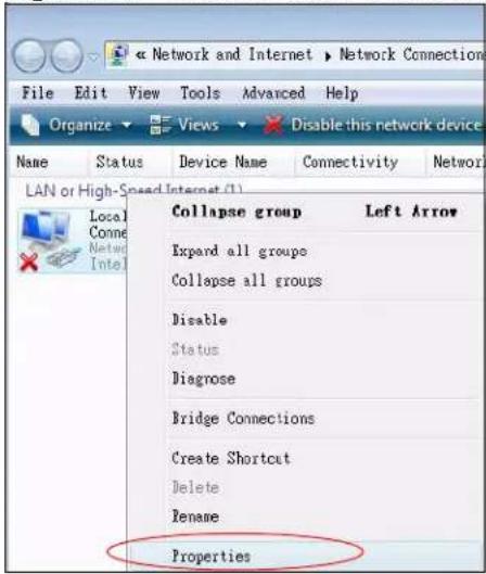
6 Select Internet Protocol Version 4 (TCP/IPv4) and click Properties.
Figure 114 Windows Vista: Local Area Connection Properties
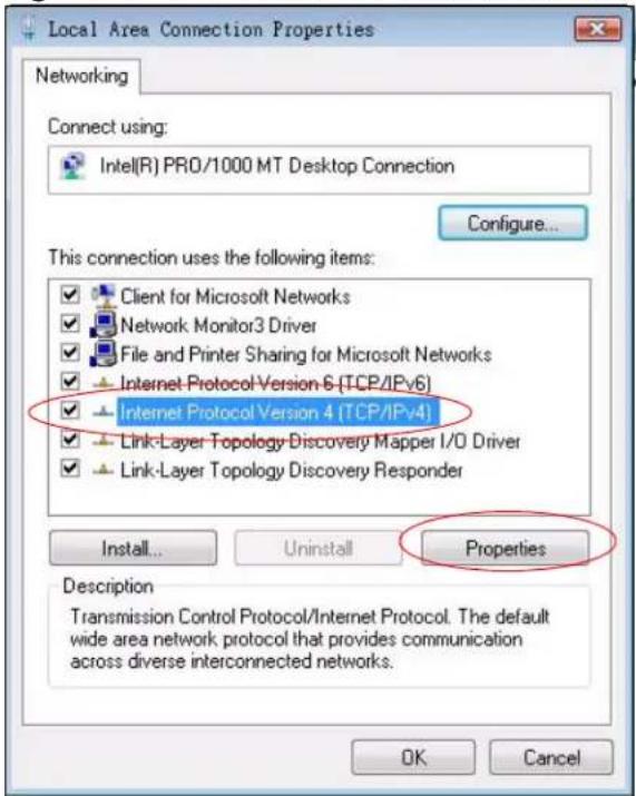
7 The Internet Protocol Version 4 (TCP/IPv4) Properties window opens (the General tab).
- If you have a dynamic IP address click Obtain an IP address automatically.
- If you have a static IP address click Use the following IP address and fill in the IP address, Subnet mask, and Default gateway fields.
- Click Advanced.
Figure 115 Windows Vista: Internet Protocol Version 4 (TCP/IPv4) Properties
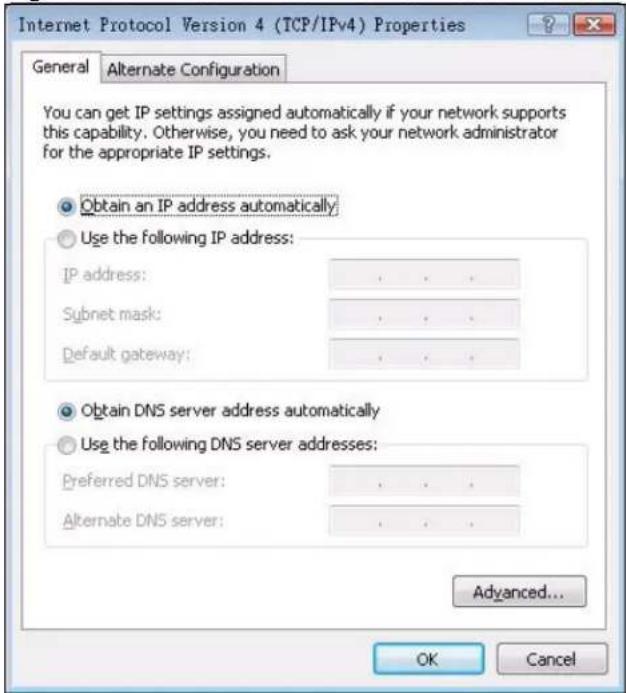
8 If you do not know your gateway's IP address, remove any previously installed gateways in the IP Settings tab and click OK.
Do one or more of the following if you want to configure additional IP addresses:
• In the IP Settings tab, in IP addresses, click Add.
- In TCP/IP Address, type an IP address in IP address and a subnet mask in Subnet mask, and then click Add.
- Repeat the above two steps for each IP address you want to add.
- Configure additional default gateways in the IP Settings tab by clicking Add in Default gateways.
- In TCP/IP Gateway Address, type the IP address of the default gateway in Gateway. To manually configure a default metric (the number of transmission hops), clear the Automatic metric check box and type a metric in Metric.
- Click Add.
- Repeat the previous three steps for each default gateway you want to add.
- Click OK when finished.
Figure 116 Windows Vista: Advanced TCP/IP Properties
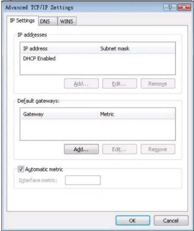
9 In the Internet Protocol Version 4 (TCP/IPv4) Properties window, (the General tab):
- Click Obtain DNS server address automatically if you do not know your DNS server IP address(es).
- If you know your DNS server IP address(es), click Use the following DNS server addresses, and type them in the Preferred DNS server and Alternate DNS server fields.
If you have previously configured DNS servers, click Advanced and then the DNS tab to order them.
Figure 117 Windows Vista: Internet Protocol Version 4 (TCP/IPv4) Properties
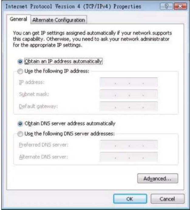
10 Click OK to close the Internet Protocol Version 4 (TCP/IPv4) Properties window.
11 Click Close to close the Local Area Connection Properties window.
12 Close the Network Connections window.
13 Turn on your AG-220 and restart your computer (if prompted).
Verifying Settings
1 Click Start, All Programs, Accessories and then Command Prompt.
2 In the Command Prompt window, type "ipconfig" and then press [ENTER]. You can also open Network Connections, right-click a network connection, click Status and then click the Support tab.
Index
A
About 81
About your ZyXEL AG-220 23
Access point (AP) 23, 37
Access point mode 25
Access point. See also AP.
Activating a profile 65
Adapter 67, 68
Ad-Hoc 24, 63
Advanced Encryption Standard 40, 117
Advanced settings 66, 67, 68
Antenna gain 76
Antenna output power 75
AP
See also access point.
AP MAC address 52
AP mode 25, 35, 73
additional setup requirements 74
advanced 77
configuration 34
MAC filter 78
requirements 27
Association list 34, 75
Authentication 53
Authentication type 39, 57
auto 40
open system 40
shared key 40
Auto authentication 40
Automatic connection 54
Automatic network scan 29, 60
B
Band 87
Bridge 76
C
CCMP 40
Certificate Authority (CA) 40, 116
Certifications 4
Notices 5
Viewing 5
Changing modes 25, 52
Channel 37, 52, 54, 63, 76, 88
Configuration 76
Configuration method 27
important note 27
Wireless Zero Configuration (WZC) 26, 27
Configuration methods
ZyXEL utility 27
Configuration status 52
Connection status 52
Contact Information 8
Continuous access mode 68
Copyright 3
Creating a new profile 62
credentials 70
Current configuration 52
Current connection status 52
Current status 74
Customer Support 8
D
Data encryption 54
Data rate 88
dBm 76
Digital ID 40
Dimensions 87
Disclaimer 3
Download 84
Driver version 81
Dynamic WEP Key Exchange 116
E
EAP (Extensible Authentication Protocol) 40
EAP authentication 40, 115
EAP type 69
EAP-PEAP 40
EAP-TLS 40
EAP-TTLS 40
Enabling OTIST 47
Encryption 54, 117
Encryption type 39, 55, 57
Environmental specifications 87
F
Fast power save 68
FCC Interference Statement 4
Frequency 37, 66, 87
G
Getting started 23
Graphics icons key 22
H
Hardware connections 26
Help 28
Hide SSID 76
Humidity 87
|
IEEE 802.1x 40, 58, 69
Industrial Scientific Medical Band 87
Infrastructure 24
Initialization vector (IV) 118
Installation 26
Interface 87
Internet access 24
IP address
dynamic 74
setup 121
L
Link information 52, 74
Link quality 53
M
MAC 75
MAC filter 78, 86
action 79
Manual network connection 29
Maximum power save 68
Mbps 74
Message Integrity Check (MIC) 40, 117
Mode change 25
Modulation 88
N
Network interface card (NIC) 76
Network mode 53, 66
Network name 52
Network overlap 37
Network scan 60
Network sharing 74
Network type 52, 54
0
One-Touch Intelligent Security Technology (OTIST) 47
Online help 28
Open system authentication 40
OTIST 47
enabling 47
introduction 47
start 48
Output power 75, 76, 88
P
Packet collisions 53
Pairwise Master Key (PMK) 118
Passphrase 39, 55
Password phrase 39
PEAP 69, 70
Peer computer 23, 63
Physical specifications 87
Power consumption 87
Power saving mode 68
Preamble 67
Product Registration 7
Product specifications 87
Profile 52, 61
activation 65
add new 62
configure 29, 31
default 60
delete 61
edit 61
information 62
new 61, 62
Setup key 47, 68
Shared key authentication 40
Signal strength 53, 54
Site information 54
Site survey 54
scan 54
security settings 55
Sleep mode 68
SSID 29, 37, 52, 54, 74, 76, 86
Starting OTIST 48
Statistics 52
Support CD 21
Syntax conventions 21
System tray 26
Q
Quick Start Guide 21, 26, 85
R
Radio interference 86
Radio specifications 87
RADIUS 40, 41
RADIUS server 118
Real-time data traffic statistics 53
Receive rate 52
Registration
Product 7
Related Documentation 21
s
Safety Warnings 6
Save power 68, 76
Scan 54
Scan Info 63
Search 54
Security 38, 39, 52, 75, 88
data encryption 39
parameters 120
settings 76
security settings and Vista 69
Sensitivity 88
Service Set Identity (SSID) 29, 37
T
Temperature 87
Temporal Key Integrity Protocol (TKIP) 40, 117
The 69
TLS 69, 70
Total receive 53
Total transmit 53
Trademarks 3
Transmission rate 52, 62, 67, 74
Transmit key 55, 76
Transmit rate 52
Trend chart 53
Troubleshooting 85
AP connection 85
link quality 86
network communication 86
starting the ZyXEL Utility 85
TTLS 69
U
Uninstalling the ZyXEL Utility 81
Upgrading the ZyXEL Utility
important step 84
Upgrading ZyXEL Utility 84
USB 21, 87
USB port 21
User authentication 39, 118
Utility installation 26
Utility version 81
V
Validate server certificate 58
Vista 69, 70
Voltage 87
network connection 103
not available 102
preferred network 111
security setting 107
system tray icon 103
WZC (Wireless Zero Configuration) 27, 34
W
Warranty 7
Note 7
Weight 87
WEP 39, 55, 76
automatic setup 39
manual setup 39, 56, 77
passphrase 39, 55, 76
WEP (Wired Equivalent Privacy) 39
WEP Encryption 55
WEP key generation 39
WEP security 35
Wi-Fi Protected Access 40, 117
WiFi Protected Setup 41
Windows 69
Windows Vista 23, 69
Windows XP 27
Wired network 76
Wireless client 37
Wireless LAN
introduction 37
security 38
Wireless LAN (WLAN) 37
Wireless network 37
Wireless security 115
Wireless standard 53, 87
Wireless station mode 52
adapter 67, 68
advanced 66
configuration 51
security settings 55
site survey 54
trend chart 53
WLAN
Security parameters 120
WPA 40, 57, 69, 117
WPA2 40, 57, 69, 117
WPA2-Pre-Shared Key 41, 117
WPA2-PSK 41, 56, 117
WPA-PSK 41, 56, 117
WPS 41
WZC
activating 100
Z
ZyXEL AG-220 Modes 25
ZyXEL Utility 27
accessing 27
driver version number 81
exiting 27
help 28
reactivating 27
status 27
system tray icon 26
upgrading 84
version number 81
- User's Guide
- Copyright
- Disclaimer
- Trademarks
- Certifications
- Federal Communications Commission (FCC) Interference Statement
- FCC Radiation Exposure Statement
- 注意!
- Viewing Certifications
- Safety Warnings
- ZyXEL Limited Warranty
- Note
- Registration
- Customer Support
- Table of Contents
- Chapter 3
- Wireless LAN Network.... 37
- Chapter 4
- Wireless Station Mode Configuration 51
- Chapter 5
- Access Point Mode Configuration.... 73
- Chapter 6
- Maintenance 81
- Chapter 7
- Troubleshooting 85
- Appendix A
- Product Specifications 87
- Appendix B
- Access Point Mode Setup Example 89
- Appendix C
- Windows Wireless Management.... 93
- Appendix D
- Wireless Security 115
- Appendix E
- Setting up Your Computer's IP Address.... 121
- Index....135
- List of Figures
- List of Tables
- Preface
- About This User's Guide
- Related Documentation
- User Guide Feedback
- Syntax Conventions
- Graphics Icons Key
- CHAPTER 1 Getting Started
- About Your AG-220
- Note for Windows Vista Users
- Application Overview
- Station Mode
- Ad-Hoc
- Access Point Mode
- Changing AG-220 Mode
- AG-220 Hardware and Utility Installation
- ZyXEL Utility Icon
- Configuration Methods
- Enabling WZC
- Accessing the ZyXEL Utility
- CHAPTER 2 Tutorial
- Connecting to a Wireless LAN
- Creating and Using a Profile
- Configuring the AG-220 as an AP
- Wireless LAN Network
- Wireless LAN Overview
- Wireless LAN Security
- Hide SSID
- MAC Address Filter
- User Authentication and Encryption
- WEP
- Data Encryption
- Authentication Type
- IEEE 802.1x
- EAP Authentication
- WPA and WPA2
- WiFi Protected Setup
- Push Button Configuration
- PIN Configuration
- How WPS Works
- Example WPS Network Setup
- Limitations of WPS
- Introduction to OTIST
- Enabling OTIST
- AP
- Wireless Client
- Starting OTIST
- Notes on OTIST
- Wireless Station Mode Configuration
- Wireless Station Mode Overview
- ZyXEL Utility Screen Summary
- The Link Info Screen
- Trend Chart
- The Site Survey Screen
- Security Settings
- WPA-PSK/WPA2-PSK
- WPA/WPA2
- IEEE 802.1x
- Confirm Save Screen
- The Profile Screen
- Adding a New Profile
- The Advanced Screen
- The Adapter Screen
- The Adapter Screen (Windows Vista)
- Security Settings in Windows Vista
- Using PEAP in Vista
- Using TLS in Vista
- Access Point Mode Configuration
- Access Point Mode Introduction
- ZyXEL Utility Screen Summary
- Additional Setup Requirements
- The Link Info Screen
- The Configuration Screen
- The Advanced Screen
- The MAC Filter Screen
- CHAPTER 6 Maintenance
- The About Screen
- Uninstalling the ZyXEL Utility
- Windows XP
- Windows Vista
- Upgrading the ZyXEL Utility
- Troubleshooting
- Problems Starting the ZyXEL Utility
- Problem Connecting to an Access Point
- Problem with the Link Quality
- Problems Communicating With Other Computers
- Product Specifications
- Access Point Mode Setup Example
- Configuring the Computer on Which You Install the AG-220
- Configuring the Wireless Station Computer
- Windows Wireless Management
- Windows Vista
- Connecting to a Wireless Network
- Connecting to a Network Manually
- Setting Up An Ad-Hoc Network
- Windows XP
- Activating Wireless Zero Configuration
- Security Settings
- Association
- Authentication
- Authentication Properties
- Protected EAP Properties
- Smart Card or other Certificate Properties
- Ordering the Preferred Networks
- APPENDIX D Wireless Security
- Types of EAP Authentication
- EAP-MD5 (Message-Digest Algorithm 5)
- EAP-TLS (Transport Layer Security)
- EAP-TTLS (Tunneled Transport Layer Service)
- PEAP (Protected EAP)
- LEAP
- Dynamic WEP Key Exchange
- WPA and WPA2
- Encryption
- User Authentication
- WPA(2)-PSK Application Example
- WPA(2) with RADIUS Application Example
- Security Parameters Summary
- Setting up Your Computer's IP Address
- Windows 98/Me
- Installing Components
- Verifying Settings
- Windows 2000/XP
- Index
- A
- B
- C
- D
- E
- F
- G
- H
- |
- L
- M
- N
- 0
- P
- Q
- R
- s
- T
- U
- V
- W
- Z
Brand : ZYXEL
Model : AG-120
Category : Network card