KC9650TLE - Cooker KELVINATOR - Free user manual and instructions
Find the device manual for free KC9650TLE KELVINATOR in PDF.


| Product Type | Freestanding Gas Cooker with Electric Oven |
| Brand | Kelvinator |
| Model | KC9650TLE |
| Overall Dimensions (H x W x D) | 890 mm x 900 mm x 600 mm |
| Oven Capacity | 105 L |
| Oven Functions | Traditional, Delicate, Top Oven, Grill, Fan Assisted Grill, Thermofan, Defrosting, Rotisserie |
| Hob Burners | 5 Gas Burners: Triple Ring, Fish, Rapid, Semi-Rapid, Auxiliary |
| Gas Type | Natural Gas (NG) or Universal LPG (convertible) |
| Gas Connection | 1/2" BSP male |
| Electrical Supply | 220-240 V ~ 50 Hz, 15 A |
| Total Electrical Power | ~8.8 kW (oven elements: 25+4+1950+1800+2250+1800+30+11 W) |
| Oven Light Bulb | 25 W, E14, high temperature resistant (300°C) |
| Electronic Timer | Yes, with auto cooking and timer functions |
| Safety Features | Anti-tilt chain, flame failure safety valves on gas burners, child lock on oven door (not specified) |
| Cleaning | Manual cleaning, removable oven door for thorough cleaning, removable burner parts |
| Spare Parts Availability | Genuine Kelvinator parts through authorized service centers |
| Warranty | 24 months from date of purchase |
| Installation Requirements | Must be installed by authorized person; adequate ventilation required; combustible surfaces clearance |
| Country of Origin | Not specified (likely China or South Africa) |
| Weight | Approximately 70 kg (estimated) |
Frequently Asked Questions - KC9650TLE KELVINATOR
User questions about KC9650TLE KELVINATOR
0 question about this device. Answer the ones you know or ask your own.
Ask a new question about this device
Download the instructions for your Cooker in PDF format for free! Find your manual KC9650TLE - KELVINATOR and take your electronic device back in hand. On this page are published all the documents necessary for the use of your device. KC9650TLE by KELVINATOR.
USER MANUAL KC9650TLE KELVINATOR
Thank you for choosing our product.
Please read this manual carefully before using and installing the appliance. The instructions in this manual are for the best installation, use and care of the appliance.
You will find that the clean lines and modern look of your oven blends in perfectly with your kitchen decor. The oven is easy to use and performs to a high standard.
We also make a range of products that will enhance your kitchen, such as cooker hoods, built-in hobs, built-in ceramic hobs and built-in ovens, microwaves, washing machines, tumble dryers, dishwashers and refrigerators.
We make every effort to ensure that our products meet all your requirements. Our service department is at your disposal to answer all your questions and to listen to your suggestions.
Please take not of the warranty section at the back of this manual and retain all documents related to the purchase of this product.
We are committed to providing increasingly efficient products that are easy to use, environmentally friendly, attractive and reliable.
Index
CAUTIONS
pag.3-4
Instructions for installation:
Dimensions and installation features
Electrical connection
Ventilation and gas connection
Adaptation to different types of gas
Setting the minimum flame
Burner and injector characteristic table
pag. 5
pag. 6
pag. 6
pag. 7
pag. 7
pag. 8
Instructions for use
Description of the main parts of the appliance
Ignition and operation of the burners
Advice on the use of gas burners
Oven function
Electronic programmer
pag. 8
pag. 9
pag. 9
pag. 10
pag. 11
pag. 12Instructions fo
Maintenance and cleaning
pag. 14
CAUTIONS:
This Appliance should be installed in accordance with local gas regulations and only used in a well ventilated space. Read the instructions before installing or using this appliance.
Before using the oven we suggest:
- Heat the oven at maximum temperature for 45 minutes to remove unpleasant odours and smoke caused by working residues and thermal insulation.
- Carefully clean the oven with warm, soapy water and rinse it. Do not use a hose or spray water onto the appliance.
- Very important: Keep this instruction booklet safe for useful references.
- This appliance is designed for use in private homes.
- This appliance is not intended for use by young children.
- Do not touch the heating elements inside the oven.
- When the grill is on, all the accessible elements are hot, hence, keep children away from these elements.
- This appliance should be installed by an authorised person and in accordance with the manufacturer's installation instructions, local gas fitting regulations, municipal building codes, electrical wiring regulations and local water supply regulations.
- Before switching this appliance on, check that it is correctly regulated for the type of gas available (see relevant section).
- Before maintenance or cleaning, disconnect the appliance from the mains and wait for it to cool down. Do not use harsh abrasive cleaners or sharp metal scrapers to clean the oven door glass as they can scratch the surface, which may result in the glass shattering.
- When the burners are lit, make sure that the flame is always regular. Before removing the saucepan/pot, turn the burners off.
- Servicing of this appliance should only be carried out by authorised personnel.
- If the electricity supply cord is damaged, it must be replaced by authorised personnel or qualified person in order to avoid hazard.
- The use of a gas appliance produces heat and humidity in a room. Make sure that the room is well ventilated, keeping natural ventilation outlets open or installing a cooker hood.
- If a gas appliance is used for a long period of time then it may require extra ventilation (opening a window or increasing the volume of the cooker hood).
- Never line the oven with aluminium sheets.
- Be careful not to use saucepans/pots with unstable or deformed bottoms on the burners to avoid overturning or spilling.
- If the mains of a burner is turned off accidentally, turn off the control knob. Only light the oven again after waiting at least a minute.
- Keep packaging out of reach of children at all times.
- Always use oven gloves when removing and replacing food in the oven.
- Do not let children sit down or play with the oven door. Do not use the drop down door as a stool to reach cabinets.
- Do not remove the plug by pulling the cable.
- DO NOT SPRAY AEROSOLS IN THE VICINITY OF THE APPLIANCE WHILE IT IS IN OPERATION.
- DO NOT USE OR STORE FLAMMABLE LIQUIDS OR ITEMS IN THE VICINITY OF THE APPLIANCE OR IN THE UTILITY DRAWER.
This electric appliance complies with the following directives :
- 89/336/EEC (electromagnetic compatibility)
- 89/109/EEC (foodstuffs)
- 73/23/EEC + 93/68/EEC (low voltage)
- 90/396/EEC ( gas appliance )
Instructions for Installation
DIMENSIONS AND INSTALLATION FEATURES
Warning:
a) Prior to installation, ensure that the local distribution conditions (nature of the gas and gas pressure) and the adjustment of the appliance are compatible;
b) The adjustment conditions for this appliance are stated on data plate;
c) This appliance is not connected to a combustion products evacuation device. It shall be installed and connected in accordance with current installation regulations. Particular attention shall be given to the relevant requirements regarding ventilation.


The cooker is supplied with an anti-tilting chain to prevent the appliance from tilting forward and accidental damage to the gas pipe. Take the expansion with hook and make an adequate hole in the wall behind, at the same height as the chain fixing area. Insert the plug into the hole and then screw in the hook until it is firmly fixed to the wall. Fix the chain to the hook. Adjust to level of the cooker inserting the feet provided.

natural_image
Simple line drawing of a room with patterned walls and a small object on the wall (no text or symbols)For a situation where the appliance is between two cupboards and the anti tilt chain cannot be fitted we suggest securing by screwing through the both sides of the cupboards into the sides of the cooker. The screws should be
fitted as follows. Position the oven between the cupboards in it's final position, then mark the location of the pilot hole inside the cupboard. Refer to the diagram below for the location of the pilot hole. Use 3.5mm diameter drill bit to drill the pilot hole through the cupboard and both sides of the cooker. Before drilling, check your measurements to ensure the pilot holes are located within the range specified in the diagram. A drilled hole in the
side of the cooker which is outside the range specified may void the warrantee. Inspect cupboards thoroughly before drilling to avoid damage to electrical wires or gas lines. Fix two 12 gauge x 40mm long self tapping screws through the pilot holes inside both cupboards and into the side of the cooker.
Note! Screw length is based on cupboard thickness of 20mm, gap between cupboard and oven of 10mm. Screw length could vary depending on cupboard material thickness and gap between oven and cupboards.
Note! The screws must be accessible for removal if the cooker requires service. Cupboards must not be built over these screws.
Equipment type:
free standing (class 1)
Insulation class:
class 1
THE MANUFACTURER DECLINES ANY AND ALL RESPONSIBILITIES FOR DAMAGES TO THINGS OR INJURIES TO PERSONS OR ANIMALS DERIVING FROM INCORRECT INSTALLATION OR USE OF THE EQUIPMENT.
ELECTRICAL CONNECTION
The appliance is fitted with an Australian approved 15 Amp flexible cord and plug which must be connected to a correctly earthed socket outlet. The manufacturer is not liable for any direct or indirect damage caused by faulty installation or connection. It is therefore necessary that all installation and connection operations are carried out by qualified personnel complying with the local and general regulations in force.
The wire section on the cable must not be less Than1.5mm (3×1.5cable). Use only the special cables available at our service centers.

natural_image
Line drawing of a hand inserting a component into a device (no text or symbols)
CONNECTION OF THE FEEDING CABLE TO THE MAINS
Connect the feeding cable to a plug suitable for the load indicated on the rating plate of the product. In case of a direct connection to the mains (cable without plug), it is necessary to insert a suitable omnipolar switch before the appliance, with minimum opening between contacts of 3 mm (the grounding wire should not be
interrupted by the switch).
Before connecting to the mains, make sure that:
- The electrical counter, the safety valve, the feeding line and the socket are adequate to withstand the maximum load required(see rating plate).
- The supply system is regularly grounded, according to the regulations in force.
- The socket or the omnipolar switch can easily be reached after the installation of the oven.
- After carrying out the connection to the mains, check that the supplying cable does not come into contact with parts subject to heating.
● Never use reductions, shunts, adaptors which can cause overheating or burning.
The manufacturer is not liable for any direct or indirect damage caused by faulty installation or connection. It is therefore necessary that all installation and connection operations are carried out by qualified personnel complying with the local and general regulations in force.

natural_image
Diagram showing a crossed black line intersecting two mechanical components (no text or symbols)Electrical features
| Oven light | 25W |
| Spit motor | 4W |
| Upper heating element | 1950W |
| Bottom heating element | 1800W |
| Grill heating element | 2250W |
| Circular heating element | 1800W |
| Ventilator motor | 30W |
| Cooling fan | 11W |
This appliance shall be installed only by authorised persons and in accordance with the manufacturer's installation instructions, local gas fitting regulations, municipal building codes, electrical wiring regulations, local water supply regulations.
Ventilation
In general, the appliance should have adequate ventilation for complete combustion of gas, proper flueing and to maintain temperature of immediate surroundings within safe limits.
Combustible Surfaces
Any adjoining wall surface situated within 200mm from the edge of any hob burner must be a suitable non-combustible material for a height of 150mm for the entire length of the hob. Any combustible construction above the hotplate must be at least 600mm above the top of the burner and no construction shall be within 450mm above the top of the burner. Zero clearance is permitted on side and rear adjoining surfaces below the hob.
Gas connection
The appliance must be connected to the gas supply or the cylinder according to the specifications of the standards and after checking that it is adjusted for the type of gas available.
The gas connection is male 1/2" BSP and is situated 55mm from the right and 560mm from the floor. It's necessity of changing the flexible tube when the national conditions require it. There are two ways to carry out
the connection to the main gas line:
A. The Cooker can be connected with the cuprum material. Loosen the tie-in down and connect one terminal of the pipe with the gas elbow
B. The cooker can be connected with a Flexible Hose, which is 10mm ID, class B or D,
between 1 - 1.2m long. The hose should not be subjected to abrasion, kinking or permanent deformation and should be able to be inspected along its entire length. Unions compatible with the hose fittings must be used and connections tested for gas leaks. The flexible tube shall be fitted in such a way that it cannot come into contact with a moveable part of the housing unit (e.g. a drawer) and does not pass through any space susceptible of becoming congested .The fixed consumer piping outlet should be at approximately the same height as the cooker connection point, pointing downwards and approximately 150mm to the side of the cooker. The hose should be clear of the floor when the cooker is in the installed position. Fix one end of the chain on the screw next to the gas inlet connection and the other end should be anchored to the floor/wall so that the chain prevents strain on the hose connections when he cooker is pulled forward.
The appliance is factory set for Natural gas. The test point pressure should be adjusted to with 10th bar Wok burner operating at maximum.
The appliance is set up to operate with the gas specified on the gas type label placed on the back of the appliance.
To perform these operations the qualified installer will follow the indications given in the "Adaptation to the various types of gas" section. For safer operation make sure that the supply pressure respects the values given in the "Table of burner and injector characteristics".
If installing for use with gas tank, gas regulator suitable for a supply pressure of 12 is part of the gas tank supply and the test point pressure is adjusted to . 29mbar
Once the appliance has been installed, make sure that the gas pipe is neither squashed or damaged by moving parts.
Before Leaving - Check all connections for gas leaks with soap and water. DO NOT use a naked flame for detecting leaks. Ignite all burners both individually and separately to ensure correct operation of gas valves, burners and ignition. Turn gas taps to low flame position and observe stability of the flame for each burner individually and separately. When satisfied with the operation of the cooker, please instruct the user on the correct method of operation. In case the appliance fails to operate correctly after all checks have been carried out, refer to the authorised service provider in your area.
Adaptation to different types of gas
When converting from Universal LPG to Natural Gas ensure that the LPG test point is removed and replaced with the CE Approved NG Regulator supplied in this kit. The test point pressure must be adjusted to 20mbar with the largest burner operating on maximum flame.
When converting from Natural Gas to Universal LPG ensure that the NG regulator is removed and replaced with the Test Point Assembly supplied in this kit. An CE Approved gas regulator suitable for a supply pressure of 29mbar should be part of the gas tank supply and the test point pressure must be adjusted to 29mbar.
To adapt the appliance to a gas different from that for which it was set up (see gas type label inside the warming compartment door) proceed as follows:
- remove the grids
- remove the burners caps and burner heads
● with a 7 mm socket spanner unscrew and remove the injectors. - replace the injectors with those supplied corresponding to the gas available (see burner and injector characteristics Table)
- replace the various parts proceeding in reverse.

natural_image
Illustration of hands holding a container with a lid and a dial, no text or symbols present
natural_image
Mechanical assembly diagram showing a central shaft and surrounding components (no text or labels)When converting from Natural Gas to EnRG that theNG regulator is removed and replaced with the Test Point Assembly. A gas regulator suitable for a supply pressure of should be part of the gas tank supply and the test point pressure should be adjusted to the pressure according to the data plate.
Setting the minimum flame
The flame on the small output is regulated by the factory. When the injectors have been replaced or there are special mains pressure conditions, it may be necessary to regulate the minimum flame again. The operations necessary to set the minimum flame are as following:
● light the burner ;
● turn the knob to the minimum position ;
● take out the knob (and gasket if there is one);

LPG TO NG: Use a thin blade screwdriver to turn the by-pass screw located above left of the gas valve, shaft as shown right. Turn gently the by-pass screw clockwise to the end completely then turn it anti-clockwise 1 turn for the Triple ring, 7/8 turn for the Fish, 3/4 turn for the Rapid, 1/2 turn for the Semi-Rapid and 3/8 turn for the Auxiliary.
NG TO LPG: Use a thin blade screwdriver to turn the by-pass screw located above left of the gas valve shaft as shown right. Turn gently the by-pass screw clockwise to the end.
1 put the knob back on and turn it quickly from the maximum position to the minimum position, checking that the flame does not go out;
for burners with safety valve make sure that the regulation obtained is sufficient to maintain heating of the thermocouple. If it is not, increase the minimum
THE BURNERS REQUIRE NO REGULATION OF THE PRIMARY AIR.
ABNORMAL OPERATION
ANY OF THE FOLLOWING ARE CONSIDERED TO BE ABNORMAL OPERATION
AND MAY REQUIRE SERVICING:
1 Yellow tipping of the hob burner flame.
lSooting up of cooking utensils.
lBurners not igniting properly.
lBurners failing to remain alight.
lBurners extinguished by oven door.
lGas valves, which are difficult to turn.
IN CASE THE APPLIANCE FAILS TO OPERATE CORRECTLY, CONTACT
THE AUTHORISED SERVICE PROVIDER IN YOUR AREA.
DESCRIPTION OF SYMBOLS

FRONT LEFT BURNER

FRONT CENTRAL BURNER

CENTRAL BURNER

REAR LEFT BURNER

REAR CENTRAL BURNER

ELECTRIC OVEN THERMOSTAT

FRONT RIGHT BURNER

LEFT CENTRAL BURNER

ELECTRIC OVEN FUNCTION KNOB

REAR RIGHT BURNER

RIGHT CENTRAL BURNER

natural_image
Simple circular diagram with horizontal and vertical lines, marked points, and a small flame symbol (no text or labels)In order to ignite a burner, it is necessary to depress the knob while rotating it anti-clockwise, till the index is aligned with the position corresponding to the maximum gas delivery (i.e. the large flame symbol). As far as the models equipped with a safety valve are concerned, once the flame is lit hold the knob
depressed for about 3-4 seconds till the device keeps the burner automatically lit. If the burner fails to ignite, wait one minute for the gas to dissipate before attempting to reignite. At this moment it is possible to adjust the flame intensity by rotating the knob anticlockwise from Such maximum position to the minimum one (i.e. the small flame symbol).
In order to turn the burner off, rotate the knob clockwise bringing the index back to the position corresponding to the closure symbol (●).
RECOMMENDATIONS
In case of electric power failure, it is necessary to carry out the above operations by putting a gas lighter or flame near the burner (in such an event, pay the utmost attention not to burn yourself).
The safety valve (for models that have this feature) intervenes in case of accidental flame failure, blocking the gas delivery (eg. Air droughts, spillage of liquids etc).
The ignition device must not be activated for longer than 15 seconds. Should the ignition manoeuvre fail, or should the burner accidentally be turned off, immediately close the activation knob and repeat the process after one minute.
Once the ignition has taken place, adjust the flame according to your needs.
Advice on the use of gas burners
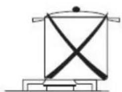
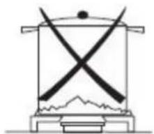
For lower gas consumption and a better yield, use saucepans with diameter suitable for the burners, avoiding the flame coming up round the side of the saucepan (see the Container Table). Use only flat-bottomed pans.
As soon as a liquid starts to boil, turn the flame down to a level sufficient to maintain boiling.
During cooking, when using fats and oils, be very careful because if they overheat they could catch fire.
natural_image
Simple line drawing of a mechanical or electrical component with no text or symbols
natural_image
Simple line drawing of a mechanical device with two crossed arms and a base, no text or symbols present.
natural_image
Simple line drawing of a cooking pot with a flame at the base (no text or symbols)Container table (use flat-bottomed saucepans)
| Bumer | min Saucepan (mm) | max Saucepan (mm) |
| Auxiliary | 90 | 160 |
| Semi-rapid | 130 | 180 |
| Rapid | 150 | 260 |
| Triple ring | 210 | 260 |
Instructions for Use
(oven)
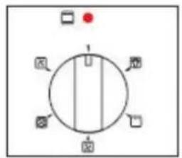
ELECTRIC OVEN THERMOSTAT KNOB
Selection of cooking temperature is carried out by turning the knob clockwise to the required temperature, between 60°C and MAX i. If the appliance is with an electric oven, the warning light will come on when the oven is heating up. When it goes out it means that it reaches the required temperature. Regular flashing means that oven temperature is being constantly maintained at the programmed level.
ELECTRIC OVEN CONTROL KNOB
Each of the functions listed below can be used only together with the correct temperature.


flowchart
graph TD
    A["Red Dot"] --> B((Center))
    B --> C["Node 1"]
    B --> D["Node 2"]
    B --> E["Node 3"]
    B --> F["Node 4"]
    B --> G["Node 5"]
    B --> H["Node 6"]
    B --> I["Node 7"]
    B --> J["Node 8"]
    B --> K["Node 9"]
    B --> L["Node 10"]
8-Function
5-Function
B
The selector B and thermostat A control is used to select the various oven functions and to choose the cooking temperatures best corresponding to the food to be cooked. During oven operation the lamp will always remain on.
The lamp of the oven is on, with no heating elements operated (electrical resistances). During oven operation the lamp will always remain on

TRADITIONAL COOKING
THERMOSTAT SELECTOR SWITCH FROM 60°C TO MAX
The heat is provided from the top and bottom elements. The oven must be preheated before the food is placed inside. Static cooking provides optimum results with: cakes, pizzas, bread and for gentle slow cooking of casseroles. Characteristics of static cooking: heat provided from above and below, cooking is possible only on middle shelf and should be centrally located in the oven.
DELICATE COOKING
THERMOSTAT SELECTOR SWITCH FROM 60°C TO MAX

Ideal for pastries and cakes with wet covering and little sugar and damp desserts in moulds. Excellent results can also be achieved in completing cooking at the bottom and with dishes requiring heat in the Lower area in particular. The plate is best inserted at bottom level.

TOP OVEN COOKING
THERMOSTAT SELECTOR SWITCH FROM 60°C TO MAX
Top oven - Use for brown food at the end of cooking.
GRILL COOKING
THERMOSTAT SELECTOR SWITCH FROM 60°C TO MAX

Grill Element - Use for toasting and melting cheese or browning. The cooking time should be no longer than 5 minutes. To operate, please select Full Grill Function along with the temperature.
FAN ASSISTED GRILL COOKING
THERMOSTAT SELECTOR SWITCH FROM 60°C TO 200°C

Use of the Grill Element and Fan. Use for grilling meats, vegetables and poultry. Preheat oven, place food on grill rack in baking tray and place in the middle of the oven. Other food may be cooked underneath whilst grilling. The oven door must be closed for all cooking methods
THERMOFAN
THERMOSTAT SELECTOR SWITCH FROM 60°C TO MAX

The circular heating element and fan come into operation and the heat is spread evenly to all shelf positions. Various types of food can be cooked on different shelves, naturally with the appropriate cooking times. The oven must be preheated before the foods are placed inside. Fan mode provides optimum results with: cakes (soft and thick), large quantities of foods and cooking various dishes simultaneously. To operate, please select Fan Forced function along with the temperature.
DEFROSTING
THERMOSTAT SELECTOR SWITCH ANY

The fan located on the bottom of the oven makes the air circulate at room temperature around the food. This is recommended for the defrosting of all types of food, but in particular for delicate types of food which do not require heat such as for example: ice cream cakes, cream or custard desserts, fruit cakes. By using the fan, the defrosting time is approximately halved. In the case of meat, fish and bread, it is possible to accelerate the process using the "Fan forced" and setting the temperature to 80^ ; TO 100^ ;
The oven door must be closed for all cooking methods.
ELECTRONIC PROGRAMMER
- Show time (0:00 - 24:00) and minutes.
- The screen shows 3 flashing numbers and 'AUTO' if the power is turned on.
- In order to set correct time. press the button first, then + or - button to change move the figure forward/backward until the exact time is shown.
Manual operation setting:
Press the ⏻ button to remove the flashing 'AUTO'.
If 'AUTO' is lit then automatic or semi automatic programme has been set.
Press the ⏻ button to remove 'AUTO' and turn the manual operation on.

Automatic setting (full automatic starting and ending time):
-
Press 📋 to set the cooking time.
-
Press 📂 to set the cooking finish time.
3.Set temperature and cooking modes by using the thermostat and selector knobs.
Once this is done, 'AUTO' will start flashing, which means that the cooking process of the oven is set.
For example: if the cooking time takes 45 minutes and you want it to end at 14:00.
Press 📄 and set the cooking time to 45 minutes, then press 🌐 and set the cooking to end at 14:00. After the above setting, the display will show the real time and flash 'AUTO'. This means that the cooking process has been memorized. When the clock turns 13:15, the oven will automatically start cooking. 🌐 and 'AUTO' will start flashing.
When the clock turns 14:00, the cooking process will be done, the alarm will ring and 'AUTO will flash. Press the △ to stop the ringing.
Semi automatic setting (automatic time limit and ending time):
- Press 📄 button to set the time limit (10 hours maximum)
The oven will start immediately. 📌 and 'AUTO' will flash. When the time limit has finished, the cooking operation will turn off automatically. 'AUTO' will flash and the alarm will ring. Press 🔒 to stop the ringing.
- Press 📋 to set the ending time (23 hours 59 minutes maximum)
The oven will start immediately. 📄 and 'AUTO' will flash. When the clock displays the ending time the cooking operation will, the cooking operation will turn off automatically. 'AUTO' will flash and the alarm will ring. Press 🔒 to stop the ringing.
When the relevant button is pressed the time setting will be shown.
When the 📋 is pressed and the time is set to 0 then the current timer setting will be cancelled.
If button is pressed again, the oven will be set to manual cooking operation.
Timer:
Press the □ button and then + or - button until the desired time is shown on the screen. Once the timer has been set, the correct time and the □ will be displayed. The timer will begin immediately.
When the ☐ button is pressed, the remaining time will be shown. When the set time has been reached the alarm will ring. Press the ☐ button to stop the ringing.
Notice:
Once the relevant button has been pressed, the setting must be done within 5 seconds.
In the case of a blackout, the set time as well as the real time will be reset. When power has returned, the display will show 3 '0's and 'AUTO' will be shown. This means that the oven has been automatically reset.
Table of contents:
| Selector knob setting | Food to be cooked | Weight (in kg) | Level from below | Preheating time (Minutes) | Temperature (°C) | Time in minutes(*) |
Traditional cooking  | Duck | 1 | 3 | 15 | 200 | 65-75 |
| Roast veal or beef | 1 | 3 | 15 | 200 | 70-75 | |
| Pork roast | 1 | 3 | 15 | 200 | 70-80 | |
| Biscuits(short pastry) | - | 3 | 15 | 180 | 15-20 | |
| Tarts | 1 | 3 | 15 | 180 | 30-35 | |
Top oven  | Browning food to perfect cooking | - | 3-4 | 220 | 15 | |
Grilling  | Soles and cuttle fish | 1 | 4 | 5 | Max | 8-10 |
| Squid and prawn kebabs | 1 | 4 | 5 | Max | 6-8 | |
| Cod filet | 1 | 4 | 5 | Max | 10 | |
| Grilled vegetables | 1 | 3/4 | 5 | Max | 10-15 | |
| Veal steal | 1 | 4 | 5 | Max | 15-20 | |
| Cutlets | 1 | 4 | 5 | Max | 15-20 | |
| Hamburgers | 1 | 4 | 5 | Max | 7-10 | |
| Mackerels | 1 | 4 | 5 | Max | 15-20 | |
| Toasted sandwiches | - | 4 | 5 | Max | 2-3 | |
| With rotisserie(where prevent) Veal on the spit | Max | |||||
| Chicken on the spit | 1.0 | - | 5 | Max | 80-90 | |
| Lamb on the spit | 1.5 | - | 5 | Max | 70-80 | |
| 1.0 | - | 5 | Max | 70-80 | ||
Fan Assisted Grill  | Grilled chicken Fish Veal Chicken + Potatoes Lamb | 1.5 | 3 | 5 | 200 | 55-60 |
| 1.5 | 3 | 5 | 200 | 30-35 | ||
Baking  | Tarts | 0.5 | 3 | 15 | 180 | 20-30 |
| Fruit cakes | 1 | 2/3 | 15 | 180 | 40-45 | |
| Fruitcake | 0.7 | 3 | 15 | 180 | 40-50 | |
| Sponge cake | 0.5 | 3 | 15 | 160 | 25-30 | |
| Stuffed pancakes(on 2 racks) | 1.2 | 2-4 | 15 | 200 | 30-35 | |
| Small cakes(on 2 rakes) | 0.6 | 2-4 | 15 | 190 | 20-25 | |
| Cheese puffs(on 2cakes) | 0.4 | 2-4 | 15 | 210 | 15-20 | |
| Cream puffs(on 3 cakes) | 0.7 | 1-3-5 | 15 | 180 | 20-25 | |
| Biscuits(on 3 racks) | 0.7 | 1-3-5 | 15 | 180 | 20-25 | |
| Meringues(on 3 racks) | 0.5 | 1-3-5 | 15 | 90 | 180 | |
Defrosting  | All frozen food |
FAN OVEN


SHELF POSITIONS
Maintenance and Cleaning
Do not use a hose pipe to spray the appliance.
Do not use a steam cleaner on the appliance.
Wash the enamelled parts with warm water and detergent.
Do not use abrasive products.
Wash the burners and their parts frequently with boiling water and detergent and make sure to remove any deposits that could block the flame outlet.
Rinse the stainless steel parts with water and dry them with a soft cloth.
To clean the hob, use a damp sponge or cloth. If too much water is used it could penetrate the internal parts and damage electrical parts. The grids of the hob can be washed in the sink or in the dishwasher.
For persistent stains use normal non- abrasive detergents.
Products specifically for this use are available on the market. Hot water and vinegar can be used.
Clean the glass parts with hot water, avoiding the use of rough cloths.
Do not use stainless steel pads or acids for cleaning.
To prevent ignition difficulties, carefully clean the lighting spark plugs regularly (ceramic and electrode).
If the knobs become difficult to turn, contact a qualified person to lubricate them.
In order to retain the brightness of the enamel parts it is necessary to clean the oven after each cooking session.
ALWAYS CLEAN THE APPLIANCE IMMEDIATELY AFTER ANY FOOD SPILLAGE.
TO MAINTAIN SAFE OPERATION, IT IS RECOMMENDED THAT THE PRODUCT BE INSPECTED EVERY FIVE YEARS BY AN AUTHORISED SERVICE AGENT.
Ovens with facility to lower grill for cleaning purposes
1 Warning: ensure that all controls are in the "OFF" position and wait the grill element cooling.
2 Support the front of the grill element while you remove the knurled screw retaining the element.
3 Lower the front of the element carefully to the rest position.
4 When cleaning the oven make sure do not apply any forces to the grill element
5 When the cleaning is complete, carefully remove any cleaning chemicals and water from the grill element.
6 Carefully raise the front of the element into position and secure with the knurled screw.
NEVER USE THE OVEN WITH THE GRILL ELEMENT HANGING DOWN!
Important. In case of burners removal for cleaning purposes, we recommend to make sure that all parts are correctly positioned before igniting the burners again.
THE GRIDS OF THE COOKING PLANE ARE EQUIPPED WITH SUITABLE RUBBER PADS, ITS PURPOSE IS BOTH PROVIDING BETTER STABILITY AND AVOIDING SCRATCHES ON THE PLANE SURFACES DURING USAGE.
AFTER A POSSIBLE GRID REMOVAL FOR CLEANING AND/OR MAINTE-NANCE NEEDS, WE RECOMMEND TO VERIFY THE PRESENCE OF SUCH RUBBER PADS AND TO PUT THE GRIDS BACK IN THEIR ORIGINAL POSITION.
Cleaning the oven door
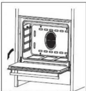
Unhooking the doors.
For a more thorough clean, you have to remove the oven door. Choose the removal and assemble method according to different structure of oven door purchased.
Proceed as follows:
- Open the door fully;
- Lift up and turn the small levers located on the two hinges;
- Grip the door on the two external sides and close it approximately half way. Unlock the door by pressing on the clamps F, then pull the door towards you lifting it out of its seat. To replace the door, reverse this sequence.
natural_image
Line drawing of an oven with a door and vent, showing internal structure without any text or symbols
natural_image
Line drawing of a hand inserting a component into a device (no text or symbols)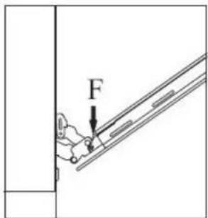

natural_image
Diagram of a mechanical assembly with an arrow indicating direction (no text or symbols)Replacing the oven bulb
Once the oven has been electrically disconnected, unscrew the glass protection cap and the bulb, Always remember to use high temperatures (300/ E14) bulb for the oven. Reassemble the glass cap and reconnect the oven after replacing the bulb.

natural_image
Diagram showing a light bulb being compressed into a cup, with arrows indicating rotation (no text or symbols)Service and Spares
In the event of your appliance requiring service, or if you wish to purchase spare parts, contact your local Kelvinator Service Centre by telephoning:
010 207 3000 (South African Customers) +27-10-207-3000 (International Customers)
Help us to help you
Please determine your type of enquiry before writing or telephoning. When you contact us we need to know:
- Your name
- Telephone Number
■ Physical Address where appliance is located
■ Model and Serial Number of the appliance - Clear and concise details of the fault
Customer Care
For general enquiries or information regarding Kelvinator appliances contact:
Customer Care Department
Kelvinator
P.O. Box 3657
Johannesburg
2000
South African Customers: 010 207 3000
International Customers: +27-10-207-3000
E-mail: service@electrolux.co.za
Guarantee Conditions
- The guarantee is valid for Twenty Four (24) months commencing when the appliance is handed over to the first retail purchaser, which must be verified by purchase invoice or similar documentation.
- Kelvinator guarantees the equipment against defective material or faulty manufacture, provided it is used for domestic use from the date of purchase by the original purchaser. If not used as above-mentioned, the warranty period will limited.
- If the appliance is used or installed more than Fifty (50) kilometres from the nearest Kelvinator Authorised Service Agent, the additional distance covered shall be for the account of the purchaser.
- The risk in regard to appliances to be repaired shall at all times remain with the purchaser.
- This guarantee is given on condition that only genuine Kelvinator parts and accessories are used at all times in the appliance.
- Kelvinator shall not be responsible for damage of any kind resulting from electricity fluctuations, faults in the building wiring, faulty installations, improper use of controls or failure to use the appliance in accordance with the operating instructions and/or general misuse and/or abuse, which would include unforeseen accidents, wear and tear, and/or earthquake, flood, lightning or any other natural disaster beyond the control of Kelvinator.
- Any attempt by an unauthorised person to repair or tamper with the appliance shall render this guarantee null and void.
- This guarantee does not include bulbs, loose glass, glass oven doors, enamelled surfaces, discolouring of stainless steel surfaces, filters and other parts subject to wear and tear.
- Kelvinator shall not be responsible in terms of this guarantee for the replacement or repair of any parts of the appliance if damaged during transit, where packaging damage is visible.
- Repairs carried out under guarantee do not extend the guarantee period for the appliance. Parts removed during guarantee repairs become the property of Kelvinator.
- This guarantee shall be available only to a purchaser of Kelvinator appliances from an authorised Electrolux Home Products/Kelvinator Dealer or Distributor in and where the appliance has been retained for use in the Republic South Africa, Namibia, Swaziland, Lesotho and Zimbabwe.
- Failure to produce documentary proof of the date or original acquisition by the original purchaser will result in normal charges being levied for the work carried out and the parts supplied.
- The liability of Kelvinator under this guarantee is limited to the replacement and/or repair of the defective parts within the guarantee period and does not extend to be installation or removal of the appliance. Furthermore, Kelvinator does not accept responsibility or liability to compensate for any consequential loss or damage of any kind caused by or due to the failure of operation or malfunction of any equipment to which this guarantee applies.
- It is at the sole discretion of Kelvinator that, in terms of guarantee, consideration be given to replace the appliance due to various parts failing of a similar nature or in the event of the appliance being in a state of beyond repair.
- Index
- CAUTIONS
- Instructions for installation:
- Instructions for use
- Maintenance and cleaning
- CAUTIONS:
- Instructions for Installation
- DIMENSIONS AND INSTALLATION FEATURES
- Warning:
- Equipment type:
- ELECTRICAL CONNECTION
- CONNECTION OF THE FEEDING CABLE TO THE MAINS
- Ventilation
- Combustible Surfaces
- Gas connection
- DESCRIPTION OF SYMBOLS
- RECOMMENDATIONS
- ELECTRIC OVEN THERMOSTAT KNOB
- ELECTRIC OVEN CONTROL KNOB
- TRADITIONAL COOKING
- DELICATE COOKING
- TOP OVEN COOKING
- GRILL COOKING
- FAN ASSISTED GRILL COOKING
- THERMOFAN
- DEFROSTING
- THERMOSTAT SELECTOR SWITCH ANY
- ELECTRONIC PROGRAMMER
- Manual operation setting:
- Timer:
- Notice:
- Service and Spares
- Help us to help you
- Customer Care
- Guarantee Conditions
Brand : KELVINATOR
Model : KC9650TLE
Category : Cooker