
VX1000C - Vacuum Cleaner NuTone - Free user manual and instructions
Find the device manual for free VX1000C NuTone in PDF.


| Product Type | Central Vacuum Power Unit (Cyclonic) |
| Model Number | VX1000C |
| Brand | NuTone |
| Dimensions (H x W x D) | 39 9/16" x 11" x 10 7/8" |
| Weight | Approximately 25 lbs (estimated) |
| Power Supply | 240 VAC, 60 Hz, dedicated 20-amp branch circuit |
| Filtration Type | Cyclonic filter media (bagless) |
| Warranty | 8-year limited warranty (model VX1000C) |
| Installation Location | Wall-mounted in garage, basement, or utility room |
| Exhaust Venting | Recommended to vent outside using Model 393 or CI330 wall caps |
| Number of Inlets Supported | Typically 3-4 inlets per system |
| Low Voltage Control | 2-conductor 18-gauge wire for remote activation via wall inlets |
| Special Features | Cyclonic action for efficient dirt separation; indicator light for system status |
| Safety Certifications | UL listed; complies with local electrical codes |
| Included Accessories | Mounting bracket, utility valve assembly, hardware |
Frequently Asked Questions - VX1000C NuTone
User questions about VX1000C NuTone
0 question about this device. Answer the ones you know or ask your own.
Ask a new question about this device
Download the instructions for your Vacuum Cleaner in PDF format for free! Find your manual VX1000C - NuTone and take your electronic device back in hand. On this page are published all the documents necessary for the use of your device. VX1000C by NuTone.
USER MANUAL VX1000C NuTone
CENTRAL CLEANING SYSTEM

INSTALLATION INSTRUCTIONS
For Power Unit Models
VX475, VX550, VX1000, VX475C, VX550C, and VX1000C
Broan-NuTone LLC
Hartford, Wisconsin
www.nutone.com
888-336-3948
To register this product, visit www.nutone.com

TABLE OF CONTENTS
SYSTEM PLANNING AND LAYOUT 3-4
Examples 3
Locating the Power Unit 4
Tubing and Wall Inlet Locations 4
GENERAL INSTALLATION GUIDE ....5-6
Tool Listing 5
Working with Plastic Tubing....5-6
INSTALLATION IN NEW CONSTRUCTION ....7-11
Wall Inlet Rough-In 7
Installing the Tubing 8
Wall Inlet Installation 9
Models CI370 & 360 Wall Inlets 9
Model 330 Wall Inlet .9
Model CI395RK Electravalve Electrified Inlet Installation 10
Model CI358 Supervalve Wall Inlet & Rough-In 11
INSTALLATION IN EXISTING CONSTRUCTION 12-19
Locating Access Keys in Existing Construction 12
Avoiding In-Wall Obstacles ....12
Installing Inlet Tubing 13-15
Wall Inlet Installation 15-18
Models Cl370 & 360 Wall Inlets .....18-19
Model 330 & CI335 Wall Inlets .....19
Floor Inlet Installation in New and Existing Construction 20
Original VacPan Installation Instructions .....21-22
ORIGINAL VACUSWEEP INLET VALVE INSTALLATION INSTRUCTIONS .....23-25
ASSEMBLING THE TUBING SYSTEM ....26-30
POWER UNIT INSTALLATION ....31-33
Mounting 31
Tubing Connections at Power Unit 32
Dimensional Chart 32
Wiring 33
FINAL SYSTEM CHECK 34
WARRANTY 35
TROUBLESHOOTING GUIDE ....36-37
SYSTEM PLANNING AND LAYOUT
The NuTone central cleaning system consists of a power unit, PVC tubing and fittings, wall inlets, a flexible hose and various cleaning attachments.
The power unit is designed to be wall-mounted away from the living area of the home and connected to the living area by means of permanently installed in-wall tubing, fittings and inlets.
Generally, an installation will require 3 to 4 inlets and 16 to 20 feet of tubing per inlet. It is suggested that a floor plan be used to more accurately determine the quantity of materials needed.
Use the following examples as an aid in planning the installation in either new or existing construction. You should be able to adapt the examples shown to your specific home layout.
THE RANCH STYLE HOUSE
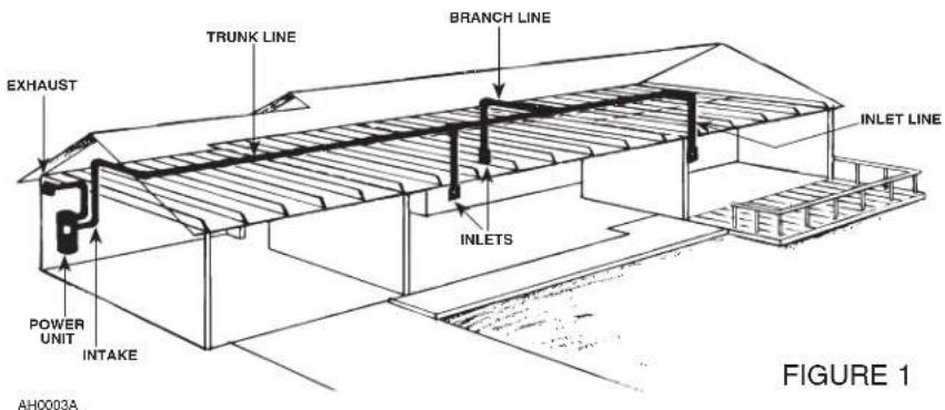
Here the power unit is mounted in the garage. The intake and exhaust tubing, the only exposed tubing in the installation, runs up the garage wall and into the attic. The trunk line runs horizontally through the attic from the power unit to the farthest inlet location. Branch lines spread throughout the attic, connecting the trunk line to the inlet tubing. Each inlet tube is threaded vertically through an inside wall. Located in hallways and in large rooms, the inlets are placed to provide maximum access to all cleaning areas. See Figure 1.
THE TWO-STORY HOUSE
A double-trunk line system is commonly used in two-story houses. In the installation shown at right, the power unit is mounted in the basement. The intake tubing runs up the basement wall and connects to the main trunk line, which runs along the unfinished basement ceiling. Two first-floor inlets are connected to the basement trunk line by vertical inlet lines run through interior walls. In the center of the house, a vertical branch line runs from the basement trunk line, through stacked closets, up into the attic. A second trunk line runs across the attic and two branch lines connect to inlet lines which are dropped down through upstairs interior walls. See Figure 2.

THE SPLIT-LEVEL HOUSE
Like the two-story house, the split level installation commonly calls for a two-level trunk line. Here, the power unit is located in the garage. The intake tubing runs exposed up the garage wall and into the ground level section's attic. Two branch lines connect this part of the trunk line to inlet lines which are dropped inside interior walls. A vertical branch line runs to the upstairs attic, where the trunk line branches into a T-shape. This trunk line connects to two upstairs inlet lines and to one inlet line which drops through an upstairs wall and down into the third-level utility room to service this entire level. See Figure 3.

LOCATING THE POWER UNIT
- Locate the power unit at the lowest possible position away from the general living area in an accessible location for changing the filter bag or debris bucket.
- When planning, remember the power unit is equipped with an inlet to service a garage, basement, utility room, etc., wherever it is located.
- Locate the power unit within six feet of a grounded electrical outlet. The VX475 and VX550 power units require a 120 V, dedicated 20-amp branch circuit with a NEMA 5-20R receptacle. The VX1000 power unit requires a 240 VAC, dedicated 20-amp branch circuit with a NEMA 6-20R receptacle.
- Do not locate the power unit close to a source of extreme heat (i.e., water heater) or in an area with a high ambient temperature (i.e., attic, furnace room).
- If the power unit is located in a closet or a small utility room, make sure the area is well-ventilated (i.e., with door louvers).
- Exhausting the power unit to the outside is recommended for optimal performance. The exhaust should not be vented into a wall, a ceiling or a concealed space in the house. The exhaust line should be vented outside the home using a Model 393 or CI330 wall caps.
TUBING AND WALL INLET LOCATIONS
- Locate inlets on interior walls, choosing central locations which allow several rooms to be cleaned from a single inlet using a 30-foot long hose.
- The tubing installation should consist of a main trunk line running from the farthest wall inlet to the power unit location, with branch lines running to each additional inlet. Keep all tubing lines as straight as possible and use as few fittings as possible.
- Beginning at the area farthest from the power unit, choose a tentative inlet location. Measure 30 feet from the proposed inlet location to the farthest corner of the rooms to be cleaned by that inlet to determine if inlet location is proper. If working from blueprints (or building plans drawn at 1/4'' = 1 ft. scale), use a 71/2'' chain as your guide to determine inlet locations.
- Locate inlets within six feet of an electrical receptacle to allow use of optional current-carrying hose.
- Be sure inlets will not be blocked by doors or furniture.
- Be sure inlets will not interfere with electrical, plumbing or other mechanical installations.
- Move tentative inlet location if necessary. Use the same procedure to determine each additional inlet location, always working toward the power unit.
GENERAL INSTALLATION GUIDE
WARNING
When applicable local regulations comprise more restrictive installation and/or certification requirements, the aforementioned requirements prevail on those of this document and the installer agrees to conform to these at his own expenses.
TOOL LISTING
Depending on your installation, you may require the use of these tools. The power tools are recommended to make your installation proceed quickly. Also, plan a mask when cutting ducting (PVC dust) and gloves when using glue.
- Wire Strippers • 1/4" Drill
• Utility Knife • Putty Knife - Knife • Hammer
-
2 1/2 " Hole Saw • Keyhole Saw
• 1/2" Drill • Cold Chisel -
Level • Flashlight
- Drill Bit • Electrical Tape
- Screwdriver • Safety Glasses
- Wrench • Hacksaw
- Tape Measurer
WORKING WITH PLASTIC TUBING
Cutting the Tubing
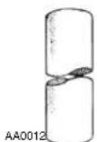
Before you cut a length of tube, accurately measure the length you need. Allow 5/8" of tubing for inserting into fittings and 1 ½" for placing into flexible tubing. Cut the plastic tubing with a hacksaw, making sure that the cut is exactly square. (You can use a tube cutter if one is available.) Use wire cutters or tin snips to cut flexible tubing. The 8" lengths of flexible tubing supplied with each inlet should not be cut. See Figure 4.


Use a small knife to remove any burrs from the inside of the tube. You can also use steel wool to remove burrs. The burrs must be removed or they may impede air flow of form clogs by snagging hair and carpet thread. See Figure 5.
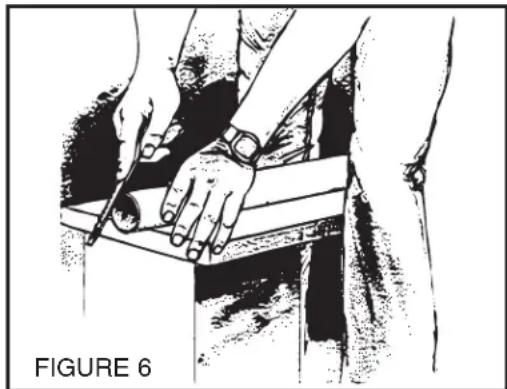
Next, use a file to slightly bevel the outside of the tube so that it will easily slide into the fitting. Use steel wool or a light grained sandpaper to buff the surface of the tube which will be glued. This will clean the tube and assure a good seal. See Figure 6.
Making a Joint
Insert the tube into the fitting, aligning the two parts as they will be installed. Mark the tube and the fitting so that you can quickly realign the joint. See Figure 7.

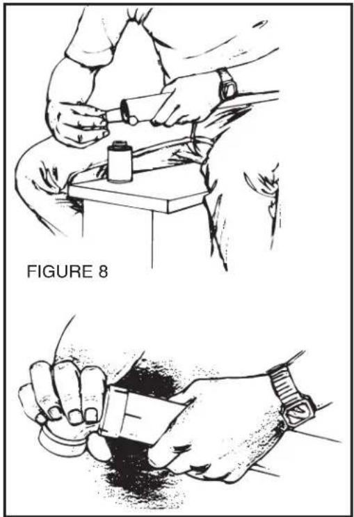
Apply cement only to the outside of the tube. Dab the cement generously in an inch-wide band. Insert the tube into the fitting with the alignment marks a quarter turn apart, and then quickly push and turn the fitting to align the marks and spread the cement. Allow one minute for the joint to dry. You may also use electrical tape or duct tape to further seal the joint. See Figure 8.
Cementing Flexible Tubing
Make sure the ends of the flexible tubing are even—trim if necessary. When you join flexible tubing to plastic tubing or to an inlet mounting plate, apply cement to both the inside of the flexible tubing and the outside of the plastic tubing or mounting plate tubing ring. Twist the two pieces as you join them to evenly spread the glue. Allow five minutes for the cement to set in flexible tubing. You may also use electrical tape or duct tape to further seal the joint.
Secure Wire to Tubing
The low-voltage power wiring is run along with the tubing. To insure that the wire is secure and will not hang-up in a wall, use electrical tape to attach the wire to the tubing. Tape the wire approximately every 12-18 inches. See Figure 9.

INSTALLATION IN NEW CONSTRUCTION
WALL INLET ROUGH-IN
Once the locations for the wall inlets have been determined, mount all inlet brackets.
- Choose the appropriate mounting bracket for the inlet being installed. (See chart)
| Rough-In Series | ||||||||||
| 395 396-1 396-3 CI301RK CI3303RK CF329 CF361 CF361F CI395RK | ||||||||||
| Wall Valve Series | 330 X | X | X | |||||||
| 360 | X | X | X | X | X | |||||
| CI335 | X | |||||||||
| CI358 | Rough-in and wall valve sold together | |||||||||
| CI370 | X | X | X | X | X | |||||
| CI390 | X | |||||||||
| CI395 | X | |||||||||
| CI398 X | X | X | ||||||||
- To locate a bracket on a wall stud, measure approximately 18" up from finished floor level. (Height may vary according to individual preference.)
MODEL CF361 & CF361F (For Use with CI370 and 360 Inlets)
- Refer to Figure 10. Nail bracket to the side of the stud so that the front edge of the bracket is flush to the front of the stud. (The bracket may also be nailed to the front edge of the stud. See face mounting illustrated. For face mounting, use locating tabs on bracket for proper alignment.)


- Refer to Figure 11. Remove cardboard from plaster guard frame. Using four (4) provided screws, attach the appropriate flanged fitting and inlet seal to back of inlet.
- Replace cardboard in plaster guard frame.
MODEL CF329 (For Use with 330 Inlets)
- When using Model CF329, glue elbow to mounting plate. Attach to stud as shown in Figure 12.

INSTALLING THE TUBING
Use the following installation guidelines when installing tubing.
- Start tubing installation at farthest inlet and work toward the power unit.
- Tubing run to the power unit should be as straight as possible.
- When assembling sections with elbows and tees, make sure the curve in the fitting is aligned so that the air flows toward the power unit.
- Branch lines should always join the trunk line from above or from the same level. Never join a branch line from an angle below the trunk line.
- Refer to Figure 25 on page 9. Run low voltage wiring (Model 376UL) and secure wiring to tubing as tubing is installed. Model CF380 Pipe Support can be used to support long runs of tubing (position near joists) and to clip wire along tubing. Secure tubing to joists or studs. Leave approximately 6" of wire for connection to each inlet.
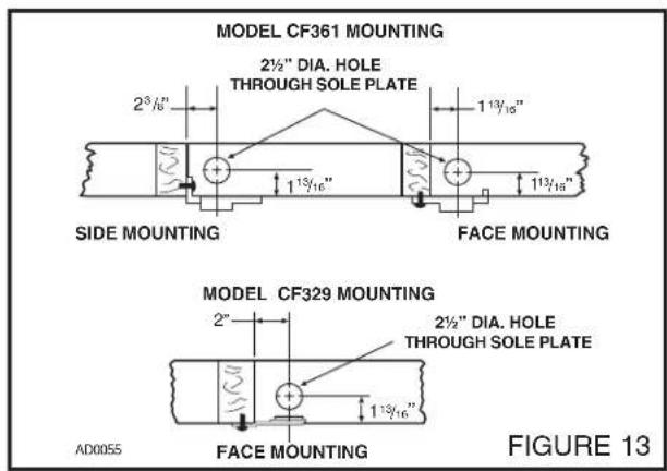
- Cut a 2 ½" diameter hole in sole plate, header or stud directly in line with opening of inlet bracket fitting.
NOTE: See Figure 13 for center line dimensions.
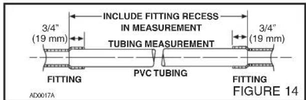
- Refer to Figure 14. Measure length of tubing needed to connect inlet to trunk line. Allow approximately 3/4" of tubing for inserting into fittings.
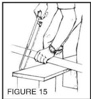
- Refer to Figure 15. Cut tubing, keeping cut square.
- Refer to Figure 16. Remove burrs from both inside and outside of tubing.
- Before cementing, pre-assemble section to inlet fitting, check for proper length.
- Refer to Figure 17. Apply PVC cement (Model 379) to outside of tubing. Coat tubing approximately 1" back. Take care to keep cement from inside of tube.
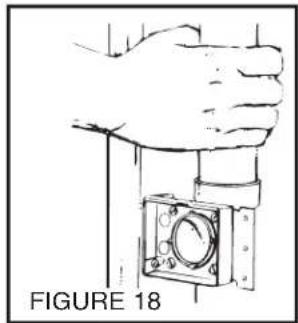
- Refer to Figure 18. Insert tubing into fitting with a twisting motion to evenly spread cement. Be sure tubing is firmly seated in fitting.
- If fittings have been attached to tubing at the end opposite the inlet bracket, be sure alignment is proper before cement sets.
- Refer to Figure 19. Tape wire to tubing to hold in place and insert through hole in inlet bracket.
- Connect each inlet line and branch line into main trunk line. Complete low voltage wiring as main trunk line is continued back to power unit.
CAUTION
When tubing is run through the wall stud, sole plate, headers or else where building materials will be attached, place a nail (Model 378) over that area (on both sides if necessary) to prevent nails from piercing tubing.



WALL INLET INSTALLATION
Model CI370 Wall Inlet (CF361 and CF361F Rough-In)
- Remove the cardboard plaster guard.
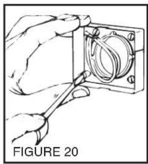
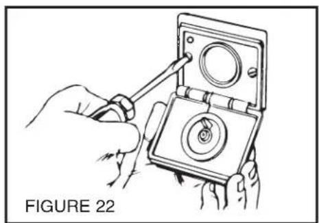
- Refer to Figure 20. For some drywall or panel construction, the plaster frame will extend beyond the finished wall. In this case, remove plaster frame from mounting bracket by removing mounting screws.
NOTE: When using the model CF361 and CF361F inlet bracket on walls thinner than 1/2", use a 1/4" spacer (not furnished) between the wall and the inlet bracket. See Figure 23. Spacer may be made from plywood, Masonite™, etc. Contact cement may be used to hold spacer in place during assembly. Configuration of spacer may vary depending upon installation.
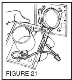
- Refer to Figure 21. Connect the red striped wire of the 2-conductor low voltage cable to the unused terminal screw on the inlet. Connect the remaining wire to the black pigtail wire. Cap off both wires using wire nut (supplied).
NOTE: The LED indicator light used in the CI370 is polarity sensitive. If the 2-conductor cable used to connect the inlet to the power unit does not have a polarity marking and the CI370 is wired backwards, no damage will result; however, the indicator will light RED instead of GREEN when the hose is inserted into the inlet. To correct this condition, simply reverse the 2-conductor connections at the CI370 inlet.
- Guide excess wire back through the hole in inlet bracket and flanged fitting.
- Refer to Figure 26. Place inlet into mounting bracket and secure.
NOTE: When wall inlets are installed in walls that are less than 1/2" thick or when inlets are installed back-to-back in a wall, the tube of the wall inlet may extend into elbow area of the flanged fitting and cause blockage. Shorten the wall inlet tube to prevent this condition. Refer to Figure 24.
For extra thick walls, use Model 399 Extension Sleeve to connect inlet to the flanged fitting.
Model 360 Wall Inlet (CF361 and CF361F Rough-In)
- Follow steps 1-2 as above.
- Refer to Figure 25. Connect 2-conductor low-voltage wire to terminal screws on back of wall inlet.
- Follow steps 4-5 above.
Model 330 Wall Inlet (CF329 Rough-In)
See Figure 26
- Connect 2-conductor low-voltage wire to terminal screws on back of wall inlet.
- Align inlet mounting holes with holes in mounting plate. See Figure 26.
- Place inlet into mounting plate and secure with two provided screws. See Figure 26.


CI390 & CI395 ELECTRAVALVE™ ELECTRIFIED INLET INSTALLATION (CI395RK ROUGH-IN)
- See Figure 27. Fasten the mounting plate to a stud within three studs (48") of an electrical outlet box. Measure and mark the wire 10" from the plug (A). Feed the wire through the top hole in the mounting plate (just above the circular opening). Snap the molded plug into the mounting plate as pictured (B). This will keep it secure and out of harm's way during drywalling and finishing. Line up the wire at the previously measured 10" mark with the strain of relief channel on the back of the mounting plate. Secure it in place with the supplied wire tie (C).
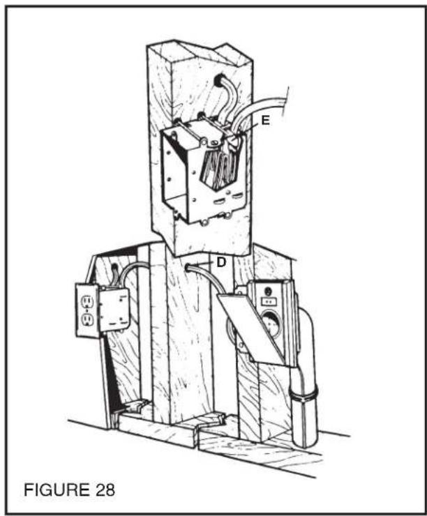
- Run the inlet wire to the adjacent electric box. If you must run wire through a stud, drill directly through the center of the stud (D).
- See Figure 28. Place the exposed ends of the two wires into the electrical box through a strain relief channel (E). Tighten the strain relief channel (do not overtighten) on the white sheathing leaving 1/2'' of this sheathing exposed inside of the outlet box.
Fold the 6" of black and white wire into the outlet box. Leave the wires to be connected by the electrician when plug receptacles are being installed. (Attention: Power tools such as routers are not recommended for use with the inlet installation, as removal of drywall with these devices may cause damage to the mounting plate and/or inlet plug).
- Once drywall and finishing processes have been completed, remove molded plug from mounting plate (with the aid of a slot screwdriver) and snap it into the wing slot at the back of the inlet (F). (NOTE: molded plug fits one way only, with the narrow opening at the top). Insert inlet into the mounting plate and secure inlet to mounting plate with screws provided.
NOTE: All electrical devices such as the electrified inlet should be reported to the construction electrician for listing on the inspection report for building inspection purposes.
NOTE: Plumb inlet to tubing using NuTone Model CF382S 90° ELL fitting.
WARNING
All location and installation direct connect electrified wall valves must conform with all local and municipal building codes.

C1358 SUPERVALVE™ WALL INLET & ROUGH-IN KIT See Figure 29

SAFETY INSTRUCTIONS
FOR HOUSEHOLD USE ONLY. INSTALL ONLY ON A NOMINAL 120 V, 60 Hz, 7 A SUPPLY PROTECTED BY A MAXIMUM 15 A OVERCURRENT PROTECTIVE DEVICE.
THE PIN CONNECTOR ON THIS TYPE A WALL VALVE IS INTENDED FOR USE ON A NOMINAL 120 V, 60 Hz, 7 A SUPPLY ONLY. IT IS REQUIRED TO BE WIRED BY A QUALIFIED ELECTRICIAN AND IS REQUIRED TO CONFIRM TO LOCAL ELECTRICAL CODES.
WARNING
Do not operate on wet surfaces!
New Construction
- Install BUILDING WIRE CONDUCTORS (1) through the approved type electrical CONNECTOR (2) (supplied) until they protrude approximately six inches from connector. Seat connector firmly into the opening atop the WIRING COMPARTMENT (4). Insert and secure LOCKING TAB (3).
- Splice wires from INLET VALVE RECEPTACLE (7) to the protruding building wire conductors with no. 31 TWIST-ON WIRE CONNECTORS (8) (not supplied).
NOTE: WHITE wire to WHITE wire & BLACK wire to BLACK wire.
- Feed LOW VOLTAGE RELAY WIRES (5) through opening in the LVT COVER PLATE (6) and connect to the two contact screws of INLET VALVE FACE PLATE (9).
- Push Inlet Valve face plate (10) into MOUNTING PLATE (11). At the same time, push ELECTRICAL CONDUCTORS (12) and connectors (8) into WIRING COMPARTMENT (4). Back out the two screws that hold the wiring compartment in place. Slip upper FINISHED WALL CLIP (13) under the screw\heads and tightly fasten both wiring compartment and upper finished-wall clip (13) with MOUNTING SCREWS (supplied).
- Install the lower FINISHED WALL CLIP (14) with screws (supplied).
- Secure Inlet Valve face plate (10) to mounting plate (11) using the two supplied color matched SCREWS (15).

No. LR 61865 No. 27Z2

Finished Construction
After pipe, low voltage relay control wire, electrical building wires and opening in wall has been cut:
- Remove mounting plate NAILING FLANGE (16). Use a hack saw or score with razor knife along dotted line and snap off.
- Repeat step one (from NEW CONSTRUCTION).
- Install modified mounting plate with short 90° ELL glued in position into wall opening.
- Repeat steps 2 - 6 (from NEW CONSTRUCTION).
INSTALLATION IN EXISTING CONSTRUCTION
LOCATING ACCESS KEYS IN EXISTING CONSTRUCTION
Unless your home is a ranch-style house where a single trunk line can run directly through the attic or basement, you should first investigate your house to find the key to running your tubing from level to level. Look for an accessible area free from obstructions that will accommodate the 2" tubing.
If you understand how your existing home is constructed, it can be relatively easy to find access routes to run the tubing. Refer again to the illustrations on pages 3-4 as you consider your home construction.
Some of the keys you might find in your home are illustrated here.
Stacked Closets or Laundry Chute
Many homes will have an upstairs closet located directly above a downstairs closet. It is easy to run the tubing from one floor level to another inside these stacked closets. In these installations the tubing is often left exposed inside the closets. See Figure 30. A laundry chute could also provide access from basement to upper floors. You may also want to consider running exposed tubing through cabinets or cupboards.
Cold-Air Return
A cold-air return often provides a straight run from basement to other levels of the house. See Figure 31. The ductwork is easily cut for access. Seal around the tube when completing the installation.
Use the following procedures for installation in existing construction. Wall inlets in existing construction may be accessed from below (basement or crawl space) or from above (attic). Instructions apply to either method.
Starting from farthest wall inlet location, install each inlet as described below. Working back toward power unit, connect each inlet line and branch line into main trunk line. See page 26. Complete low voltage wiring as main trunk line is continued back to power unit. Mount power unit and complete wiring. See pages 31-33.
AVOIDING IN-WALL OBSTACLES
The tubing which connects the inlet into the trunk line is threaded through interior partition walls. After you've chosen an inlet location, make sure the wall doesn't contain some hidden obstacle which will prevent you from running tubing to the inlet.


Exterior Walls. The insulation in these walls will prevent you from running tubing through them.
Electrical Wiring. Wiring may not obstruct your tubing, but you should always make sure that tubing does not damage the wiring. Electrical outlets and wall switches are signs of wiring.
Ductwork Avoid choosing a section of wall that contains ducting. If you see signs of ductwork—such as floor or ceiling registers—move your inlet location to another section of the wall.
Plumbing. Plumbing may or may not prevent you from running tubing through a wall. If you must choose a plumbing wall for an inlet location, be extremely careful when making a cutout in the wall.
Wall Studs. Make sure your location is between wall studs. Locate studs by tapping walls, looking for electrical outlet (usually fastened to studs), or noticing finishing nails in the floor molding.
INSTALLING THE INLET TUBING
When your planning is complete, you will have to determine where all the inlets and the power unit will be located. You have also mapped out the location of your trunk line and found the access you need to run vertical tubing from one level of your house to another level. You should have acquainted yourself with the methods of joining plastic tubing and acquired the tools you'll need to install your NuTone Central Vacuum System. Now, you can begin installation.
The first step to install the inlet tubing which connects the wall inlets to the branch lines. As explained before, the inlet lines run inside interior walls. You will find access to these walls through your attic or basement. Briefly, you want to find the exact location in the wall, drill an access hole through the wall plate or header, and insert the tubing into the wall cavity.
This part of your installation requires close observation and careful measurements. Take your time and make sure you accurately line up your access holes with the locations you've chosen for your wall inlets.
Locating Attic Access Holes
Drill the access holes directly above the inlet location. To accurately locate the access hole, you must find the space between wall studs where the inlet is to be located. Observe the area around the inlet location. Look for references you might be able to find in the attic: electrical wiring, ductwork, doorways, etc. Measure and note the distance from these references to the inlet location.
Enter the attic and find the inlet wall. Have a helper downstairs knock on the top of the wall right above the inlet location; locate the general area by following the sound. Most likely, you will have to clear away insulation. Ask your helper to continue knocking until you locate the area between wall studs directly above the inlet location.
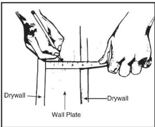
Next, measure the thickness of the wall. Mark the exact center of the wall where you will drill the access hole. Remember that the access hole must be placed exactly in the center of the wall.
Locating Basement Access Holes
To locate access holes in the basement, remove the toe molding or baseboard at the base of the inlet wall. Carefully loosen the molding or baseboard by inserting the blade of a putty knife behind it. Force another putty knife between the first knife and the baseboard or wall. Gently hammer a cold chisel between the two knife blades, prying the loosened molding away from the baseboard or the baseboard away from the wall.
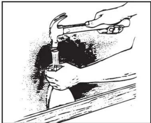
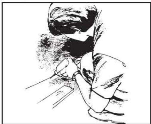
Directly below the inlet location, drill a 1/16" reference hole through the floor into the basement. (If you're drilling through carpet, use an awl to slightly open the weave. This will keep the carpet from wrapping itself around the drill bit.) Insert a piece of scrap wire or a clothes hanger into the reference hole so you can easily find the hole in the basement.
Once you've found the location in the partition wall, you must center the access hole in the middle of the wall. Measure half the thickness of the wall and mark the center of the wall where you will drill the access hole. If you cannot see the plate, you can determine this measurement from upstairs. At the nearest doorway, measure the thickness of the wall, including the baseboard.
In the basement measure a distance equal to half the thickness of the wall, using the reference hole as a starting point.
Drilling the Access Holes
Once you are certain that you've located the center of the wall directly above the inlet location, use a 2½" hole saw to cut the access hole through the wall plate or header and into the wall cavity. (A 1/2" drill is recommended.) Carefully remove the drill from the hole.

Now, use a flashlight to inspect the wall cavity through the access hole. Make sure no hidden obstacles will interfere with the tube installation. (If this inspection reveals an obstacle, find a new inlet location.) Repeat this procedure in your attic or basement until your access holes are drilled.

Assembling the Inlet Tubing
Once you've drilled the access holes, you assemble the inlet tubing and insert it into the wall cavity. Refer to "Working With Plastic Tubing" on pages 5-6 before you begin to assemble the inlet lines.
Select a section of plastic tubing and an 8" section of the flexible inlet tubing. Apply cement to the outside of the plastic tubing and to the inside of the flexible tubing. Join the two pieces together and allow 5 minutes for them to dry.

Cut a piece of low voltage wire which is long enough for the complete inlet line, allowing 6" for connections to the inlet wall plate. Secure the wire to the tubing with electrical tape.
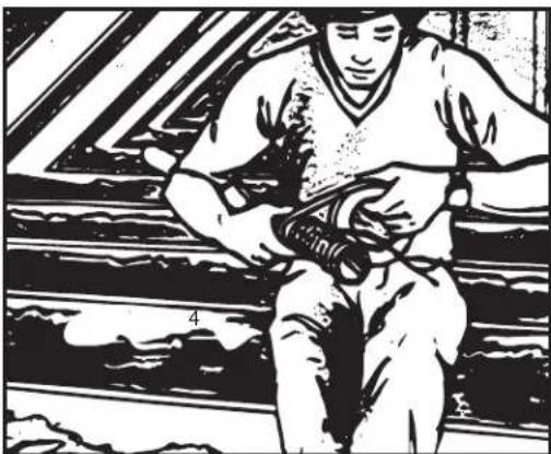
Tuck the 6" wire lead inside the flexible tubing so that it will not snag inside the wall.
If space permits, you can assemble the entire inlet line by joining two sections of tubing with a stop coupling before dropping the assembly into the access hole.

(Remember to only glue the outside of the tubing when joining two pieces of PVC tubing.) Oftentimes, tight attic spaces require you to begin your drop and then join the second section of tubing. Of course, the order of assembly, and the length of tubing required depend on your attic space and your wall height.

Whatever the case, insert the completed inlet line into the access hole and thread it down inside the wall. The inlet line should be long enough so that it extends above the joists in the attic; at this height, it can be easily connected to the branch and truck lines. When cutting the inlet tubing to length, remember that your inlet will be placed at 18" above the floor.

For a basement installation, assemble the tubing to the inlet flexible tubing in the same way and insert it into the access hole. A basement inlet line is necessarily shorter because it must only reach 18" from the floor to the inlet. Most of the time, Basement inlet lines are more easily installed by two
people after the inlet hole has been cut in the interior wall. See "Wall Inlet Installation."

Complete all your inlet lines, and then proceed to your inlet installations.
WALL INLET INSTALLATION
The wall inlet design allows you to work outside the wall—where assembly is easy and all the parts you need are accessible. First, you make a cutout into the wall and locate the flexible tubing attached to the inlet line which you previously threaded into the wall. Then, you attach the flexible tubing to the inlet mounting plate, assemble the other inlet parts, and make the wiring connections. You place the inlet assembly into the wall cutout, sandwiching the wall between the inner and outer parts, and secure the inlet tightly to the wall with two screws.
Assemble and install the wall inlet as shown in the illustrations and as explained in the next few pages. Be careful and patient as you make your first cutout and install your first inlet by following the procedure step by step—the other inlets will be easy to install in very little time.
Making the Wall Inlet Cutout
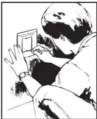
The wall inlet should be located 18" on-center from the floor and directly in line with the attic or basement inlet tubing hole you have already drilled in the wall plate or header. the wall inlet cutout must be exactly 3 1/8 " high by 2 1/8 " wide. It is crucial that you make an accurate cutout, and we have supplied a template to help you.
Place the template against the wall so that it is 18" on-center from the floor. Use a level along the top edge of the template to make sure it is square to the wall. Mark your
wall for the cutout by tracing around the inside of the template. Then use your pencil to mark the screw hole locations through punched holes at the top and bottom of the template. Remove the template from the wall.

Use an awl or icepick to punch pilot holes where you marked the two hole locations. Now, drill two 3/8" diameter holes, using the pilot holes as the centers. Locate and drill these holes exactly as marked with the template.
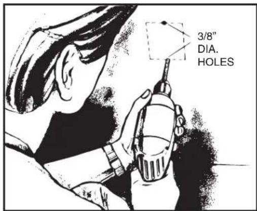
Also drill four pilot holes in the four corners of the marked area. Make sure these holes are located inside the marked line. Then, using a utility knife, score along the inside of the marked line. For plaster walls, score the plaster deeply, being careful to stay inside the marked line.

Next, use a keyhole saw or a sabersaw to make the cutout. Again, be extremely careful to cut along the inside of the marked line.
CAUTION
When cutting into plaster walls, make sure the plaster is firm and secure around the cutout area.

Attaching the Inlet Mounting Plate
Reach through the inlet hole and locate the inlet tubing. Raise it up inside the wall until you locate the inlet tubing. If the inlet is connected from the basement, have a helper insert the inlet tubing into the access hole until you can see the flexible tubing. Then, pull the flexible tubing through the inlet hole and remove the low voltage wiring from inside the tube. If the end of the flexible tubing is not even, trim it so that it is exactly even.

Now, remove the nail flange (used for new construction) from the inlet mounting plate. Use pliers to bend this flange along the scored lines until you can break it off.

Apply cement to both the inside of the flexible tubing and to the outside of the mounting plate's tube ring. Insert the mounting plate's tube ring in the flexible tubing and twisting the pieces as you join them to spread the cement, and align the mounting plate in a vertical position.


Hold the assembly in place for a few minutes as the cement sets; allow 5 minutes for the cement to completely dry.
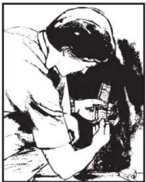


Now, strip the ends of the two low voltage wires, and then connect the wires to the screw terminals on the back of the inlet cover. Make sure the wires are tightly secured
under the terminal screws. When the wiring is complete, assemble the inlet cover to the tube guard and mounting plate. Insert the top screw through the entire inlet assembly until the screw engages the mounting plate.
Completing Inlet Assembly
Once you have attached the mounting plate to the flexible tubing, pull the low voltage wire through the top wiring hole in the mounting plate.
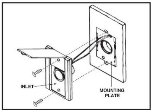
Installing the Inlet
When you place the inlet into the wall cutout, the mounting plate and tube guard slip inside the wall; the inlet cover remains on the outside.

Holding the inlet assembly between your thumbs and fingers, angle the bottom of the mounting plate into the cutout. Push the assembly downward until you have clearance at the top of the cutout.
Push the top of the mounting plate into the cutout and lift the assembly upward until the top screw seats in the predrilled hole.

At this point, the wall should be sandwiched between the mounting plate and the frame plate.


Insert the bottom screw into the inlet cover and through the other parts. Give the screw a few turns until it firmly engages in the mounting plate. Now, level and slightly lower the assembly. Make sure the wall is sandwiched between the inner and outer parts—you'll be able to feel if mounting plate is firmly centered on the inside of the wall.
Hold the inlet in place and gradually tighten down each screw a little bit at a time. (If you completely tighten down one screw at a time, the mounting plate may pull away from the wall at the loose end and slip back into the cutout.)
Complete all your wall inlet installations in this manner. If your cutouts are accurate, each wall inlet will install more quickly and easily.

CI370 OR 360 SERIES INLETS (CF361 OR CF361F ROUGH-IN)
NOTE: If 330 wall inlet is being used refer to Models 330 & CI335 Series Wall Inlet on next page.
- If area is clear, cut an inlet opening in the wall approximately 18" above the floor. Make sure wall opening and 2½" tube hole line up (Figure 32).

NOTE: If the wall for mounting the Model 360 inlet is less than 1/2", a spacer must be used. See Figure 23 on page 9 as a guide.
-
Cut a length of tubing that will extend from inlet opening to a point below floor level (or above ceiling level in attic installation). Tape low voltage wire to tube and insert tube through predrilled hole to a level opposite the wall opening.
-
Apply cement to tube and install flanged wall fitting. Make sure fitting is well seated and sealed (Figure 33).

- Remove plaster frame from mounting bracket. Pull low voltage wire through hole in bracket and insert bracket into cutout. Secure bracket to flanged fitting with 4 screws provided. Be sure seal is secure between flange fitting and mounting bracket (Figure 34).

- Attach the low voltage wires to terminal screws on back of wall inlet (Figure 35). If using 361 Rough-in with CI370 Series Inlets, refer to instructions on page 7, step 3, shown in Figure 10.

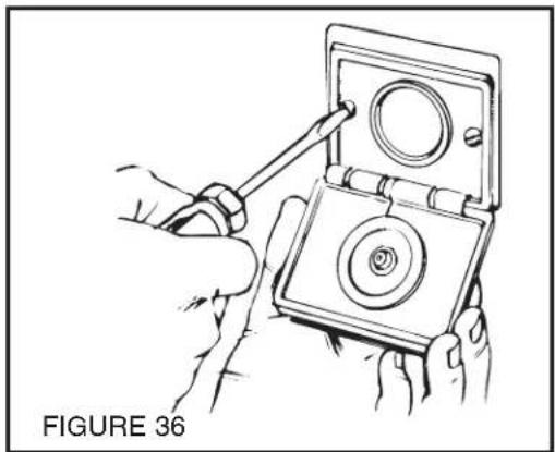
- Insert wall inlet into bracket and secure with the two screws provided (Figure 36).
MODEL 330 & CI335 SERIES WALL INLET INSTALLATION CF329 ROUGH-IN)
- Make cutout according to dimensions in Figure 37.
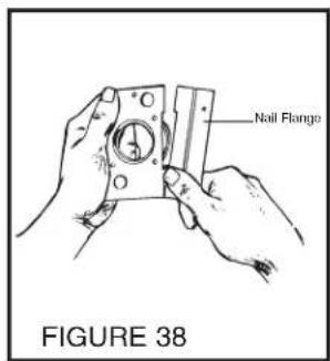
- Refer to Figure 38. Break off nail plate at scored line.
- Refer to Figure 39. Glue elbow to mounting plate, place assembly into cutout, and attach elbow to tubing inside the wall.
- Make sure mounting holes are exactly at top and bottom.
-
Connect 2-conductor low voltage wire to terminal screws on back of wall inlet.
-
Refer to Figure 40. Align inlet mounting holes with mounting plate holes, place inlet into mounting plate, and secure with provided screws.


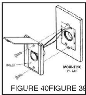
NOTE: If CF382S shorter radius elbow is used, it may be necessary to use the short mounting screw to avoid interference with elbow.
FLOOR INLET INSTALLATION IN NEW & EXISTING CONSTRUCTION
Model Cl370 or 360 Series Inlets (361 Rough-In)
- Refer to Figures 41 and 42. After floor inlet location has been selected, cut a 31/16 x 21/16 square hole in floor. Center line of inlet must be located at least 21/2 from wall to allow cover to be opened when hose is inserted.
- Determine direction of tubing and attach appropriate flanged fitting to mounting bracket with four (4) screws supplied. Be sure mounting bracket flange does not interfere with tubing and seal is securely in place.
- Refer to Figure 43. Position bracket with frame and flanged fitting assembly into cutout from below and secure to sub-floor.
- Refer to Figure 44. Large end of Model 399 extension sleeve should be cut to length to allow proper seating of inlet against floor or carpet.
- Refer to Figure 45. Pull low-voltage 2-conductor wire through mounting bracket and attach to terminal screws on back of floor inlet. Cement extension sleeve to Model Cl370 or 360 inlet. Insert extension sleeve through vinyl gasket in mounting bracket and firmly seat into flanged fitting.


- For convenience of operation, floor inlet should be installed to open back toward wall.
- Refer to Figure 43. Secure floor inlet in place with two screws.


ORIGINAL VACPAN™ INSTALLATION INSTRUCTIONS
NOTE: Please read instructions prior to installation.
INSTALLATION TIPS
- Plan the location of your ORIGINAL VACPAN to be conveniently located for sweeping clean-ups.
- Also consider ease of access of vacuum tube piping connections during installation.
- The leading edge of the ORIGINAL VACPAN must sit flush with the finished floor.
- For maximum clearance, use part no. CV382S universal short 90° elbow for connection to VACPAN.
- Do not glue the connection between ORIGINAL VACPAN and elbow to allow for future removal.
- Prior to final installation, check for an airtight seal between ORIGINAL VACPAN and elbow. Teflon tape may be used if required.
- Allow for 1/2" vertical play in vacuum tube piping at ORIGINAL VACPAN location, so that final piping connections can be made.
UNDER CABINET INSTALLATIONS
Refer to Figure 46.
- ORIGINAL VACPAN requires a minimum 2 1/4 toe kick height.
- Once the ORIGINAL VACPAN location is determined, cut a 6 3/4 " long x 1 3/4 " high slot in the cabinet toe kick to accept the ORIGINAL VACPAN.
- Run vacuum tube piping and low voltage wire from the main piping line to the ORIGINAL VACPAN location.
- Access for final piping connections must be made.
Access From Below
If access is available from below, cut an access hole through the subfloor underneath the cabinet, positioned so that final piping connections can be made by reaching through the access hole.
Access Through Cabinet Floor
Access can be made through the finished cabinet floor. Cut a 2 3/4 " x 3 1/2 " access hole, positioned so that final piping connections can be made by reaching through the access hole. CI366 Trim Plate can be used to cover the hole after installation.
Access Through Cabinet Toe Kick
Access can be made through the cabinet toe kick by cutting up to 10½" x 4" slot and using the ORIGINAL VACPAN Quick Trim Cover Plate (CI366 Trim Plate sold separately). If required, score back of Quick Trim Cover Plate with a knife and snap along grooves for height adjustment.
- Attach low voltage wires to ORIGINAL VACPAN terminal connections marked "low voltage only".
- Slide ORIGINAL VACPAN into mounting slot and secure to toe kick using two no. 6 screws provided.
- Reach through access hole and make final piping connections.
UNDER CABINET INSTALLATIONS
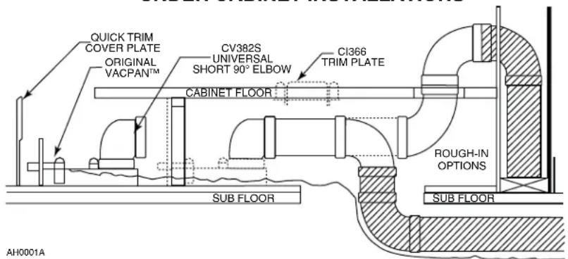
FIGURE 46
IN WALL INSTALLATIONS
Refer to Figure 47.
• ORIGINAL VACPAN can be installed between wall studs in side walls.
• ORIGINAL VACPAN should be located tight to one side in stud space.
- Once the ORIGINAL VACPAN location is determined, cut a 6 3/4 long x 1 3/4 high slot in the wall and baseboard to accept the ORIGINAL VACPAN.
- The 2 x 4 wall bottom plate between the 2 studs must be removed. This can be achieved from below using a hole saw.
- In new home construction, the bottom wall plate can be removed directly. A 6 3/4 length of 2 x 4 can be used as a temporary rough in block, that will force all trades to finish around, leaving a slot for the ORIGINAL VACPAN.
• Floor contractor must run flooring under block.
- Run vacuum tube piping and low voltage wire from the main line to ORIGINAL VACPAN location.
- Access for final piping connections must be made.
Access from Below
If access is available from below, cut an access hole through the subfloor underneath the wall between the studs, positioned so that final piping connections can be made by reaching through the access hole.
Access Through Wall
Access can be made through the finished wall. Cut a 2 3/4 " x 3 1/2 " access hole, positioned so that final piping connections can be made by reaching through the access hole. A generic cover plate can be used to cover the hole after installation (sold separately).
- Attach low voltage wires to ORIGINAL VACPAN terminal connections marked "low voltage only".
- Slide ORIGINAL VACPAN into mounting slot and secure to wall using two no. 6 screws provided.
- Reach through access hole and make final fitting connections.
IN WALL INSTALLATIONS

FIGURE 47
ORIGINAL VACUSWEEP®
INLET VALVE
INSTALLATION INSTRUCTIONS
CONNECTION FROM BELOW
Refer to Figure 48.
- Turn the power to the vacuum unit OFF. Measure distance (X) between the kickplate face and the inside edge of the cabinet. Then, add 2 3/4 " to the measured distance. See Figure 48-1. Measure out the new distance (X+2 3/4 ") from the cabinet door to the reference mark.
- Drill a small reference hole straight down through to the basement. See Figure 48-2. Locate the reference hole in the basement and verify that there are no obstructions within 2" of either side and 4" behind.
- Cut a 2½" diameter hole from the basement up into the base of the counter using the reference hole as a center. See Figure 48-3.
- Using the reference hole as a center, cut a 23/8 " high x 6/8" wide rough opening in the kickplace face. See Figure 48-4.
- Glue the long socket of the tight elbow (part no. CF382S) onto a section of 2" central vacuum pipe. Make the terminal connections to the VacuSweep® Inlet Valve by sliding the low voltage wire into wire clips. Turn the power to the vacuum unit on to test the connection. After successful completion of the test, turn power to the vacuum unit OFF. Wrap a piece of wire/string around the pipe. Using the wire/string to temporarily hold the pipe and elbow in place, insert the VacuSweep® Inlet Valve into the cabinet base and elbow. DO NOT glue this connection (Designed for friction fit). See Figure 48-5.
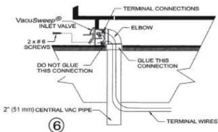
- Remove the wire/string. With the door in an open position, secure the VacuSweep® Inlet Valve to the cabinet base using no. 6 screws. See Figure 48-6. Ensure that the spring on the electrical connector has 1/8" clearance to rough opening. Continue with remainder of central vacuum connections. When the vacuum system is complete, turn the power to the vacuum unit on.
![CABINET DOOR (x) + (2 3/4" [70 mm]) REFERENCE MARK CABINET 2 3/4" (70 mm) KICKPLATE SUB FLOOR JOIST ①](/content/2026/05/920553/images/5ef6145793283913ad22bb3c88e42729f2dbaeb76d898108c09ae4829036f487.jpg)
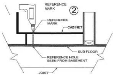

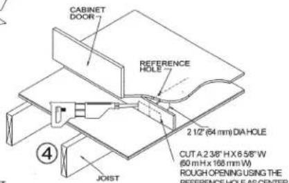

FIGURE 48
ADD045A
CONNECTION FROM BEHIND
Refer to Figure 49.
- Turn the power to the vacuum unit OFF. Choose a location under the cabinet for the VacuSweep® Inlet Valve so that it can be connected to the central vacuum pipe. Measure distance (X) between the kickplate face and the inside edge of the cabinet. Then add 2 3/4 " to the measured distance. See Figure 49-1. Measure out the new distance (X + 2 3/4 ") from the cabinet door, to the reference mark.
- Drill a small reference hole straight down through to the basement. See Figure 49-2. Locate the reference hole in the basement and verify that there are no obstructions.
-
Using a reciprocating saw, cut an access hole in the floor under the cabinet and approximately 8" behind the location of the VacuSweep® Inlet Valve reference hole so that the VacuSweep® Inlet Valve can be connected to vacuum pipe by reaching through the access hole. See Figure 49-3.
-
Using the reference hole as a center, cut a 2 3/8 " high x 6 1/8 " wide rough opening in the kickplate face. See Figure 49-4.
-
Insert a coupling (part no. CF388) onto the rear of the housing. DO NOT glue this connection (Designed for friction fit). See Figure 49-5. Make the terminal connections to the VacuSweep® Inlet Valve by sliding the low voltage wire into wire clips. Turn the power to the vacuum unit on to test the connection. After successful completion of the test, turn power to the vacuum unit OFF. Insert the VacuSweep® Inlet Valve into the cabinet base and pipe.
-
With the door in an open position, secure the VacuSweep® Inlet Valve to the cabinet base using no. 6 screws. See Figure 49-6. Ensure that the spring on the electrical connector has 1/8" clearance to rough opening. From the basement reach through the access hole and glue a section of 2" central vacuum pipe to the coupling. Continue with remainder of central vacuum connections. When the vacuum system is complete, turn the power to the vacuum unit on.
![CABINET DOOR (x) + (2 3/4" [70 mm]) REFERENCE MARK CABINET 2 3/4" (70 mm) KICKPLATE SUB FLOOR JOIST ① ② REFERENCE MARK CABINET SUB FLOOR REFERENCE HOLE SEEN FROM BASEMENT JOIST ③ CUT 8" (203 mm) ACCESS HOLE BEHIND REFERENCE HOLE ④ CABINET DOOR REFERENCE HOLE 8" (203 mm) ACCESS HOLE JOIST CUT A 2 3/8…](/content/2026/05/920553/images/c32f4fc46aa4d6a6997d0b0848698d7c3af16a70e8a76e04c271cb0528d550e2.jpg)
FIGURE 49
CONNECTION IN A WALL
Refer to Figure 50 on page 25.
- Turn the power to the vacuum unit OFF. Remove the baseboard and locate studs in the wall where VacuSweep® Inlet Valve will be installed. Locate a position where the inlet will be clear of vertical studs and have free access either up or down dependent on location of central vacuum connection to the rest of the system. See Figure 50-1.
- Holding the drill at a 45° angle and as close to the wall as possible, between located studs, drill a small reference hole through the floor and subfloor. Locate this reference hole from beneath and measure over approximately 1 7/8 " to center of base plate of wall. Ensure you have 1 1/2 " clearance from any obstacles if connecting from below. See Figure 50-2.
- If installation is from below use a 2½" diameter hole saw to remove wood floor and base plate, sufficient to locate VacuSweep® Inlet Valve centered over the reference hole. See Figure 50-3.
- Using the reference hole as a center, cut a 2 3/8 high x 6 3/8 wide rough opening in the wall and baseboard. See Figure 50-4.
- Glue the long socket of the tight elbow (part no. CF382S) onto a section of 2" central vacuum pipe. Make the terminal connections to the VacuSweep® Inlet Valve by sliding the lowvoltage wire into wire clips. Turn the power to the vacuum unit on to test the connection. After successful completion of the test, turn power to the vacuum unit OFF. Wrap a piece of wire/string around the pipe. Using the
wire/string to temporarily hold the pipe and elbow in place, insert the VacuSweep® Inlet Valve into the opening at the base of the wall and elbow. DO NOT glue this connection (Designed for friction fit). See Figure 50-5.
- Remove the wire/string. With the door in an open position, secure the VacuSweep® Inlet Valve to the wall using no. 6 screws. See Figure 50-6. Ensure that the spring on the electrical connector has 1/8" clearance to rough opening. Continue with remainder of central vacuum connections. When the vacuum system is complete, turn the power to the vacuum unit on.
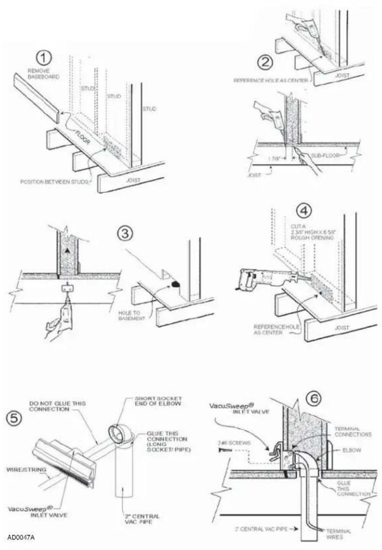
FIGURE 50
VacuSweep® Inlet Valve Rough-in Template

Cut along dotted line.
ASSEMBLING THE TUBING SYSTEM
Once you have installed all your inlets, you can complete the network of tubing that connects your inlets to the power unit. This network consists of the following parts:

90° Elbows – Used for connecting the inlet lines to the branch lines. Also used for making smooth 90° turns in branch lines or trunk lines.

45° Elbows - Used for a 45° tubing turn in branch or trunk lines.

90° Tees – Used to connect branch lines to the trunk lines.

Stop Couplings – Used to join two lengths of tubing.

Flexible Tubing – Used to bypass obstacles or to make difficult S-turns in branch lines. This tubing is supplied in a 36" length; it is not the same as the inlet flex tube.
PVC Tubing - 8' straight sections of tubing used for inlet, branch and trunk lines.
Use the tubing and fittings to run branch lines from the inlet tubing to a main trunk line. Begin at the farthest inlet from the power unit and work your way toward the power unit. When you assemble sections with elbows and tees, make sure the curve in the fitting is aligned so that the air flows toward the power unit.
Assemble the entire network of tubing and fittings, making sure every joint is accurately cut and aligned. Then, go back and cement all the joints. You may run the wiring and make the wiring connections after the network is assembled and cemented, or you may make the wiring connections as you assemble the network. Use the method that best suits your needs.
Beginning the Trunk Line
Start the inlet line which is farthest from the power unit. Place 90° elbow onto a section of tubing and align it with the inlet tubing at the height it will run across the attic joists. Mark the inlet tubing where the elbow will join, allowing 5/8" for the tubing that inserts into the fitting collar.
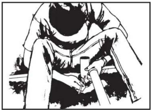
Now, cut the inlet tubing at the marked line. Make sure the cut is straight and even. Attach the elbow and check its fit. Then, insert the first section of tubing into the other end of the elbow.

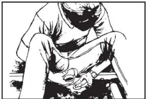

Joining Straight Lengths of Tubing
Both branch lines and the trunk lines may require lengths of tubing longer than those 8' sections supplied. Use stop couplings to join two straight lengths of tubing. Insert one end of the tubing into the stop coupling; join the second length of tubing into the other end of the stop coupling. Stop couplings are also used to join long vertical branches which run from one level to another level of a house.

Connecting a Branch Line
A branch line connects the inlet line to the trunk line. Follow the methods previously described for aligning, marking and cutting the inlet tubing. Attach a 90° elbow and run tubing from the inlet line to the trunk line.
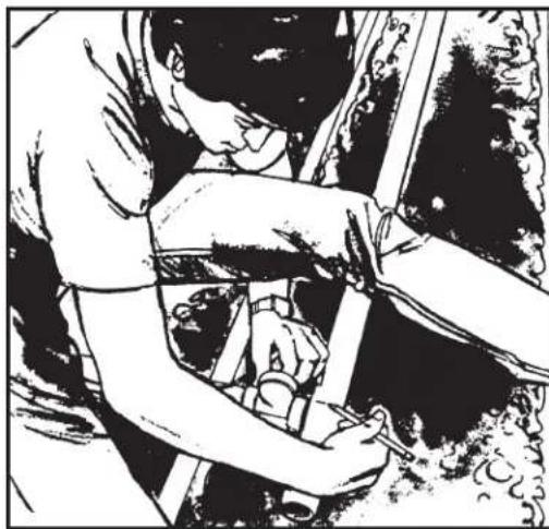
To align and measure the branch line, attach a 90° tee fitting to the trunk line. Make sure the tee connects with the air flow going toward the power unit. Align, measure, and mark the branch line for inserting it into the tee fitting. Then, cut the branch line to length and insert it into the tee. Check to make sure the cut is straight and even. Connect the next section of tubing to the out-take side of the tee fitting. Continue the trunk line until you come to another branch line junction point.
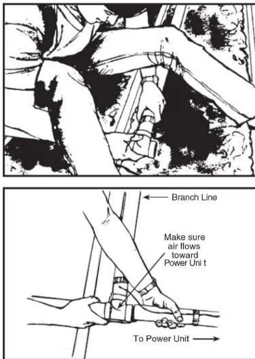
Circumventing an Obstacle
Wherever possible the branch lines should connect to the trunk line in straight paths. The fewer turns in a tubing system, the more efficient air flow. Accordingly, you should locate the inlets to avoid zig-zags in the branch lines. But, sometimes, when you just can't avoid an obstacle, you are required to construct the tubing around it.
In the example illustrated here, you might run the branch line at an angle to avoid a chimney. Then, once the branch line has run past the chimney, you can use a 45° elbow to turn the branch line back perpendicular to the trunk line. Again, the branch line and the trunk line connect with a 90° tee.
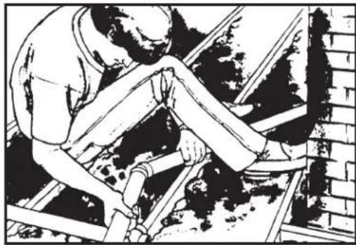
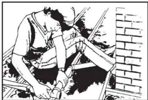

You can also use the supplied 36" piece of flexible tubing to run a branch line around an obstacle. See "Using Flexible Tubing," on page 30.
Completing the Trunk Line
Continue to run the trunk line toward the power unit, connecting all branch lines as you go along. Again, make sure you connect all fittings with the air flow toward the power unit.
Bring the trunk line to the access hole you have drilled for the power unit's intake tube. Place a 90° elbow over the hole and cut the trunk line to fit into this final elbow. Allow 5/8" of tubing to fit into the elbow's collar. Connect the elbow to the trunk line so that it aligns over the intake access hole. You will make the intake tube connection itself after you have installed the power unit.


When you are satisfied that all fittings and tubing are aligned for maximum air flow, make sure that all your cuts are square and that all joints are tight. Then, prepare the tubing and cement the joints as described in "Working With Plastic Tubing," page 5.
Connecting the Low Voltage Wiring
Ideally, you will run the wiring and make all the wiring connections after you have completed the tubing system. Of course, the inlet wiring must be run at the time the inlet tubing is threaded through the walls.
Run the low voltage wiring along the trunk line; at approximately 12"-18" intervals, use electrical tape to secure the wire to the tubing. Then, run wiring along the branch lines from the inlet lines to the trunk line. Also secure this wiring with electrical tape.
At the joint of the inlet line and the branch line, make a two-wire connection. Use wire nuts to make the connections and insulate each connection with electrical tape.

At the junction of every branch line and the trunk line, cut the trunk line wire and connect it to the branch line wire. Connect this wiring in groups of 3-one branch wire, one in-coming trunk line wire and one outgoing trunk line wire. Insulate all wire connections with electrical tape.

Complete all wiring connections up to the power unit's intake access hole. You will make this connection when you mount and connect the power unit. If, for some reason, you want to connect the wire as you go along, make the same two-wire and three-wire connections where required.
Ass embling a Basement Trunk Line
Basically, the tubing network is assemble the same way for a basement installation. Begin the trunk line at the farthest inlet line from the power unit. Measure and cut the inlet tubing to the length required to align the trunk line with the joists or ceiling. Cement the inlet tubing and connect at 90° elbow. Then, run the trunk line until you reach a branch line junction point.


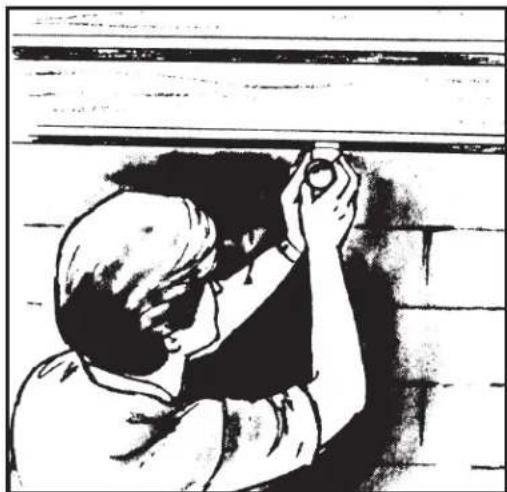
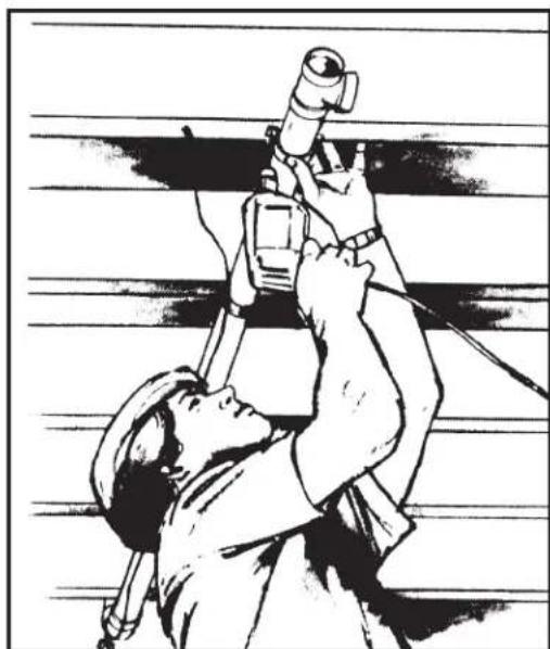
Attach the tubing to the joists or ceiling with either perforated metal or support strapping (support strapping is available from NuTone).
Make all branch line connections in the same way you would an attic installation. Make sure that all branch lines enter the trunk line at an angle that is at least levelled with the trunk line. Make sure all the fittings are oriented so the air flows toward the power unit. Complete the trunk line to the power unit location.
Using Flexible Tubing
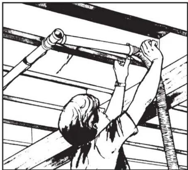
The supplied 36" length of flexible tubing may be used to circumvent an obstacle or to make a difficult turn. In the example illustrated here, the flexible tubing is used in order to run a branch line under a support beam. Attach this tubing to the PVC tubing, cementing only the outside of the PVC tubing as you would for a hard-fitting connection. Whenever you use the flexible tubing, you must secure both ends of it with support strapping.

POWER UNIT INSTALLATION
Refer to page 4 for information on locating the power unit.
MOUNTING
This section refers to Figures 51 and 52.
CAUTION
On models VX475, VX550 and VX1000, DO NOT REMOVE either of the grey seals covering the BOTTOM red cap plugs. Removing these seals will void the warranty. Only remove and use the outlets covered by the TOP green plugs. For VX475C, VX550C and VX1000C models, DO NOT REMOVE either of the grey seals covering the TOP red cap plugs. Removing these seals will void the warranty. Only remove and use the outlets covered by the BOTTOM green plugs.

Your power unit mounts to the wall using a mounting system. The wall mounting bracket, provided with your power unit, mounts to the wall. It has 4 fingers at the top and 4 others at the bottom. The power unit has 4 upper openings and 4 lower openings which are designed to slide onto the fingers of the wall mounting bracket. Be sure to follow the instructions below for proper installation.
- Locate power unit within six feet (1.82 m) of a grounded electrical outlet. NuTone's models VX475 and VX550 Series require a 120V, dedicated 20-amp branch circuit with a NEMA 5-20R receptacle. VX1000 Series require a 240 VAC, dedicated 20-amp branch circuit with a NEMA 6-20R receptacle.
- Refer to Figure 51 to maintain minimum wall clearance dimensions.
CAUTION
Make sure to fix the wall mounting bracket with the screws directly onto a stud for a solid installation.
- Position and install the wall mounting bracket with the provided screws. Refer to Figure 52 for proper mounting dimensions.
- Using the provided mounting screws, secure the mounting bracket on the wall through two upper and two lower mounting holes.
- Prior to installing the power unit onto the wall, you must do the wiring, see page 33 for more details.
- Hang power unit onto wall mounting bracket. Make sure both upper and lower mounting openings on the back of the power unit are engaged with corresponding wall bracket fingers. Pull down the power unit to secure.
- Open the door on the front side of the power unit. For VX475, VX550 & VX1000 models, make sure bag is installed properly on bag holder and holder is locked in upright position. For models VX475C, VX550C & VX1000C, make sure the cyclonic filter media is properly seated. See Homeowners Guide if necessary. Close the door.
WARNING
Do not install outdoors.
MINIMUM WALL CLEARANCES
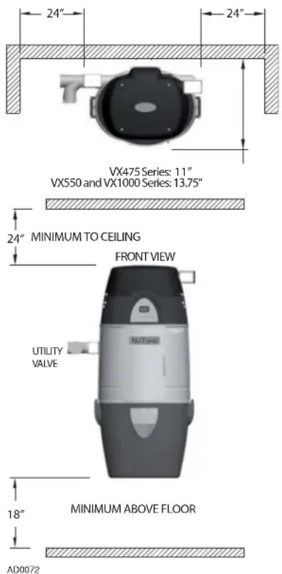
FIGURE 51

FIGURE 52
TUBING CONNECTIONS AT POWER UNIT
This section refers to Figures 53 and 54.
Your VX Series power units are capable of being connected to the intake vacuum trunk line from either side. Select the intake connection to be used. On some installations, you may connect the vacuum air intake into both intakes.
CAUTION
Models VX475, VX550 and VX1000 will attach to the upper intake connections. See Figure 53. Models VX475C, VX550C and VX1000C will attach to the lower intake connections. See Figure 54.
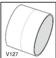
- Using provided coupling (part no. V127), attach the utility valve assembly with the vacuum trunk line feeding into the power unit. The utility valve can be installed on the left or right hand side.
- Cap off the unused intake tube with the green plastic cap provided.
- Attach exhaust tube to power unit using provided coupling (part no. V127) (if vented to the outside).
- Make sure all tubing connections are air tight.
- The exhaust should NOT be vented into a wall, ceiling or concealed space in the house. It is recommended to vent the vacuum exhaust air to the outside of the house. Exterior vented exhaust lines should be terminated using Model 393 wall caps or CI330 wall caps.
DIMENSIONAL CHART
| DIMENSION | CYCLONIC BAGGED CYCLONIC BAGGED | |||
| VX475C VX475 VX550C/1000C VX550/1000 | ||||
| A | 36 9/16" | 36 9/16" | 39 9/16" | 36 9/16" |
| B | 11" | 11" | 11" | 11" |
| C | 10 7/8" | 2 1/8" | 10 7/8" | 2 1/8" |


WIRING
This section refers to Figures 55 and 56.
Grounding Instructions—This appliance must be grounded. If it should malfunction or break down, grounding provides a path of least resistance for electric current, to reduce the risk of electric shock. This appliance is equipped with a cord having an equipment-grounding conductor and grounding plug. The plug must be plugged into an appropriate outlet that is properly installed and grounded in accordance with all local codes and ordinances.
WARNING
Improper connection of the equipment-grounding conductor can result in a risk of electric shock. Check with a qualified electrician or service person if you are in doubt as to whether the outlet is properly grounded. Do not modify the plug provided with the appliance – if it will not fit the outlet, have a proper outlet installed by a qualified electrician.
This appliance is for use on a standard 120 V a.c., dedicated 20-amp branch circuit with a NEMA 5-20R receptacle for VX475 and VX550 models. For VX1000 models, a nominal 240 V a.c., dedicated 20-amp branch circuit with NEMA 6-20R receptacle is required. Make sure that the appliance is connected to an outlet and has a grounding attachment plug that looks like the plug shown in either Figure 55 or 56 depending on the model. No adapter should be used with this appliance.
- Using crimping pliers, connect low voltage wire (18 gauge, 2-conductor, model 376-UL) to crimp connectors.
- Connect the low voltage wire to the low voltage wire harness located at the back of the power unit, the use of long nose pliers is recommended. See Figure 57.
- The power unit is equipped with a 6-foot grounded cord. Ensure power cord is plugged into a properly grounded receptacle.


FINAL SYSTEM CHECK
Be sure all inlets are closed and soil bag (for VX475, VX550 & VX1000 models) is in place. Check switch on power unit for manual on/off operation. Check that indicator light on side of power unit is lit and is in green mode.
Check each wall inlet to be sure contacts activate power unit when hose is inserted and switched on, if applicable. If using CI370 or C1358 Indicating Inlet, be sure LED on inlet is green when hose is inserted/switched on. If Central Cleaning hose is not available at the time, a short piece of wire can be used to short contacts in wall inlet to activate power unit. Check each wall inlet and tubing connection for air leaks. Check power unit for leaks around inlet tube and dirt receptacle.
Make sure the filter bag is properly installed in the power unit according to directions printed on the bag or in homeowner's manual. Remove the extra bag and owner's manual from the power unit dirt receptacle. It may be convenient to store them with the cleaning tools and accessories.
Now it's time to enjoy the benefits of a NuTone Central Cleaning System. See Homeowner's Manual for operating and care information.
WARRANTY
For Models VX475 & VX475C
NuTone
Two-Year Limited Warranty
WARRANTY OWNER: NuTone warrants to the original consumer purchaser of its products that such products will be free from defects in materials and workmanship for a period of two (2) years from the date of original purchase. THERE ARE NO OTHER WARRANTIES, EXPRESSED OR IMPLIED, INCLUDING, BUT NOT LIMITED TO, IMPLIED WARRANTIES OF MERCHANTABILITY OR FITNESS FOR A PARTICULAR PURPOSE.
During this time period, NuTone will, at its option, repair or replace, without charge, any product or part which is found to be defective under normal use and service. THIS WARRANTY DOES NOT EXTEND TO FLUORESCENT LAMP STARTERS OR TUBES, FILTERS, DUCT, ROOF CAPS, WALL CAPS AND OTHER ACCESSORIES FOR DUCTING. This warranty does not cover (a) normal maintenance and service or (b) any products or parts which have been subject to misuse, negligence, accident, improper maintenance or repair (other than by NuTone), faulty installation or installation contrary to recommended installation instructions.
The duration of any implied warranty is limited to the two-year period as specified for the express warranty. Some states do not allow limitation on how long an implied warranty lasts, so the above limitation may not apply to you.
NUTONE'S OBLIGATION TO REPAIR OR REPLACE, AT NUTONE'S OPTION, SHALL BE THE PURCHASER'S SOLE AND EXCLUSIVE REMEDY UNDER THIS WARRANTY. NUTONE SHALL NOT BE LIABLE FOR INCIDENTAL, CONSEQUENTIAL OR SPECIAL DAMAGES ARISING OUT OF OR IN CONNECTION WITH PRODUCT USE OR PERFORMANCE. Some states do not allow the exclusion or limitation of incidental or consequential damages, so the above limitation or exclusion may not apply to you. This warranty gives you specific legal rights, and you may also have other rights, which vary from state to state. This warranty supersodes all prior warranties.
WARRANTY SERVICE: To qualify for warranty service, you must (a) notify NuTone at the address stated below or telephone 1-800-543-8687, (b) give the model number and part identification and (c) describe the nature of any defect in the product or part. At the time of requesting warranty service, you must present evidence of the original purchase date.
Date of Installation Builder or Installer
Model Number and Product Description
IF YOU NEED ASSISTANCE OR SERVICE:
For the location of your nearest NuTone Independent Authorized Service Center:
Residents of the contiguous United States Dial Free: 1-800-543-8687
Please be prepared to provide:
Product model number • Date and proof of purchase • The nature of the difficulty
Residents of Alaska or Hawai should write to: NuTone Inc. Attn: Department of National Field Service, 926 West State Street, Hartford, WI 53027
Rev. 06/2009
For Models VX550 & VX550C
NuTone
Four-Year Limited Warranty
WARRANTY OWNER: NuTone warrants to the original consumer purchaser of its products that such products will be free from defects in materials and workmanship for a period of four (4) years from the date of original purchase. THERE ARE NO OTHER WARRANTIES, EXPRESSED OR IMPLIED, INCLUDING, BUT NOT LIMITED TO, IMPLIED WARRANTIES OF MERCHANTABILITY OR FITNESS FOR A PARTICULAR PURPOSE.
During this time period, NuTone will, at its option, repair or replace, without charge, any product or part which is found to be defective under normal use and service. THIS WARRANTY DOES NOT EXTEND TO FLUORESCENT LAMP STARTERS OR TUBES, FILTERS, DUCT, ROOF CAPS, WALL CAPS AND OTHER ACCESSORIES FOR DUCTING. This warranty does not cover (a) normal maintenance and service or (b) any products or parts which have been subject to misuse, negligence, accident, improper maintenance or repair (other than by NuTone), faulty installation or installation contrary to recommended installation instructions. The duration of any implied warranty is limited to the four-year period as specified for the express warranty. Some states do not allow limitation on how long an implied warranty lasts, so the above limitation may not apply to you.
NUTONE'S OBLIGATION TO REPAIR OR REPLACE, AT NUTONE'S OPTION, SHALL BE THE PURCHASER'S SOLE AND EXCLUSIVE REMEDY UNDER THIS WARRANTY. NUTONE SHALL NOT BE LIABLE FOR INCIDENTAL, CONSEQUENTIAL OR SPECIAL DAMAGES ARISING OUT OF OR IN CONNECTION WITH PRODUCT USE OR PERFORMANCE. Some states do not allow the exclusion or limitation of incidental or consequential damages, so the above limitation or exclusion may not apply to you. This warranty gives you specific legal rights, and you may also have other rights, which vary from state to state. This warranty supersedes all prior warranties.
WARRANTY SERVICE: To qualify for warranty service, you must (a) notify NuTone at the address stated below or telephone 1-800-543-8687, (b) give the model number and part identification and (c) describe the nature of any defect in the product or part. At the time of requesting warranty service, you must present evidence of the original purchase date.
Date of Installation Builder or Installer
Model Number and Product Description
IF YOU NEED ASSISTANCE OR SERVICE:
For the location of your nearest NuTone Independent Authorized Service Center:
Residents of the contiguous United States Dial Free: 1-800-543-8687
Please be prepared to provide:
Product model number · Date and proof of purchase · The nature of the difficulty
Residents of Alaska or Hawai should write to: NuTone Inc. Attn: Department of National Field Service, 926 West State Street, Hartford, WI 53027
Rev. 06/2009
For Models VX1000 & VX1000C
NuTone
Eight-Year Limited Warranty
WARRANTY OWNER: NuTone warrants to the original consumer purchaser of its products that such products will be free from defects in materials and workmanship for a period of eight (8) years from the date of original purchase. THERE ARE NO OTHER WARRANTIES, EXPRESSED OR IMPLIED, INCLUDING, BUT NOT LIMITED TO, IMPLIED WARRANTIES OF MERCHANTABILITY OR FITNESS FOR A PARTICULAR PURPOSE.
During this time period, NuTone will, at its option, repair or replace, without charge, any product or part which is found to be defective under normal use and service. THIS WARRANTY DOES NOT EXTEND TO FLUORESCENT LAMP STARTERS OR TUBES, FILTERS, DUCT, ROOF CAPS, WALL CAPS AND OTHER ACCESSORIES FOR DUCTING. This warranty does not cover (a) normal maintenance and service or (b) any products or parts which have been subject to misuse, negligence, accident, improper maintenance or repair (other than by NuTone), faulty installation or installation contrary to recommended installation instructions. The duration of any implied warranty is limited to the eight-year period as specified for the express warranty. Some states do not allow limitation on how long an implied warranty lasts, so the above limitation may not apply to you.
NUTONE'S OBLIGATION TO REPAIR OR REPLACE, AT NUTONE'S OPTION, SHALL BE THE PURCHASER'S SOLE AND EXCLUSIVE REMEDY UNDER THIS WARRANTY. NUTONE SHALL NOT BE LIABLE FOR INCIDENTAL, CONSEQUENTIAL OR SPECIAL DAMAGES ARISING OUT OF OR IN CONNECTION WITH PRODUCT USE OR PERFORMANCE. Some states do not allow the exclusion or limitation of incidental or consequential damages, so the above limitation or exclusion may not apply to you. This warranty gives you specific legal rights, and you may also have other rights, which vary from state to state. This warranty supersedes all prior warranties.
WARRANTY SERVICE: To qualify for warranty service, you must (a) notify NuTone at the address stated below or telephone 1-800-543-8687, (b) give the model number and part identification and (c) describe the nature of any defect in the product or part. At the time of requesting warranty service, you must present evidence of the original purchase date.
Date of Installation Builder or Installer
Model Number and Product Description
IF YOU NEED ASSISTANCE OR SERVICE:
For the location of your nearest NuTone Independent Authorized Service Center:
Residents of the contiguous United States Dial Free: 1-800-543-8687
Please be prepared to provide:
Product model number • Date and proof of purchase • The nature of the difficulty
Residents of Alaska or Hawai should write to: NuTone Inc. Attn: Department of National Field Service, 926 West State Street, Hartford, WI 53027
Rev. 06/2009
TROUBLESHOOTING GUIDE
Read Before Calling Service Center
Trouble Possible Cause
| 1. Loss or decrease of vacuum occurs. | 1a.Disposable filter bag or debris bucket are completely full. |
| 1b. Obstruction in the hose. A blockage in the hose can be determined by inserting the hose into any wall inlet and, while power unit is running, check each additional inlet for normal suction by holding the palm of your hand over the open inlet. If normal suction is felt at all other inlets, insert the hose into a second inlet. If the blockage still exists it is located in the hose. However, if the blockage does not occur when the hose is changed, the blockage is probably located in the tubing system leading to the original inlet. | |
| 1c. Obstruction in the tubing system inside the walls. | |
| 1d.Wall inlet cover not properly sealed. | |
| 1e.Exhaust tubing or vent clogged. | |
| 2. Power unit does not start, or shuts off during normal operation with no LED showing red or illuminated. | 2a.Defective inlet. Check other wall inlets. |
| 2b. Thermoprotector has been activated OR there is a tripped circuit breaker on the unit. | |
| 2c.Blown fuse or tripped circuit breaker on house electrical panel. | |
| 2d.Defective hose. | |
| 2e.NOTE: This would apply only to the VX550 & VX1000: microprocessor lockup. | |
| 2f. Low line voltage. | |
| 2g.Bag full sensing has been activated. | |
| 3. Power unit fails to stop when the hose is removed. | 3a.An electrical short has occurred somewhere in the system. |
| 4. Power unit shuts off during normal operation, lights on unit, wall valve and hose are all red. | 4a.Debris bucket and/or direct door not fully closed or attached. |
| 5. For VX550 & VX1000 Series. All lights on control panel flash when unit is first plugged in. | 5a.Two or more hoses may be plugged into system. |
Possible Remedy
1a. Remove disposable filter bag or empty debris bucket as described in Homeowner's Guide and install replacement.
1b. Insert handle end of hose into utility valve at power unit. Turn unit on. This will reverse normal air flow through the hose and dislodge any clogs.
1c. Insert hose end into any inlet with power unit running, place the palm of your hand over the opposite end of the hose. When you can feel the suction increase, hold your hand over the hose end for a few seconds and then quickly remove your hand. This procedure repeated several time should clear the obstruction. If the blockage is not cleared, contact your nearest Service Center.
1d. Check all wall inlet covers to be sure they are closed and sealed tightly.
1e. Inspect and remove any blockages.
2a. Replace defective wall inlet.
2b. Turn unit off for 20 minutes then plug unit back in. If unit does not start, look for the tripped circuit breaker behind the unit, a white button has popped up, push it back to reset it. If circuit breaker trips again, unplug your unit and contact your local Service Center.
2c. Replace fuse or reset circuit breaker on wall panel.
2d. Replace hose as required.
2e.1) Push Reset button while unit is engaged OR 2) Unplug unit completely for 60 seconds.
2f. Contact your local Service Center.
2g.Remove and replace disposable filter bag as described in Homeowner's Guide.
3a.A complete check of all wall inlet and power unit low-voltage control lead connections. Contact your local authorized Service Center.
4a. Check and close direct door and make sure debris bucket handles are fully locked.
5a. Check all other wall inlets, utility valve at power unit and sweep inlet valve.
NOTES
NOTES
NuTone®
926 WEST STATE STREET, HARTFORD, WI 53027
WWW.NUTONE.COM
WARRANTY
All VX Power Units are covered by a NuTone 2, 4, or 8 year warranty. Refer to your Model Number for which warranty you have. Tools and Accessories warranted for one year from date of purchase. See page 35 for details.
Product specifications subject to change without notice.


- CENTRAL CLEANING SYSTEM
- INSTALLATION INSTRUCTIONS
- TABLE OF CONTENTS
- SYSTEM PLANNING AND LAYOUT 3-4
- GENERAL INSTALLATION GUIDE ....5-6
- INSTALLATION IN NEW CONSTRUCTION ....7-11
- INSTALLATION IN EXISTING CONSTRUCTION 12-19
- ORIGINAL VACUSWEEP INLET VALVE INSTALLATION INSTRUCTIONS .....23-25
- ASSEMBLING THE TUBING SYSTEM ....26-30
- POWER UNIT INSTALLATION ....31-33
- FINAL SYSTEM CHECK 34
- WARRANTY 35
- TROUBLESHOOTING GUIDE ....36-37
- SYSTEM PLANNING AND LAYOUT
- THE RANCH STYLE HOUSE
- THE TWO-STORY HOUSE
- THE SPLIT-LEVEL HOUSE
- LOCATING THE POWER UNIT
- TUBING AND WALL INLET LOCATIONS
- GENERAL INSTALLATION GUIDE
- WARNING
- TOOL LISTING
- WORKING WITH PLASTIC TUBING
- CUTTING THE TUBING
- MAKING A JOINT
- CEMENTING FLEXIBLE TUBING
- SECURE WIRE TO TUBING
- INSTALLATION IN NEW CONSTRUCTION
- WALL INLET ROUGH-IN
- MODEL CF361 & CF361F (FOR USE WITH CI370 AND 360 INLETS)
- MODEL CF329 (FOR USE WITH 330 INLETS)
- INSTALLING THE TUBING
- CAUTION
- WALL INLET INSTALLATION
- MODEL CI370 WALL INLET (CF361 AND CF361F ROUGH-IN)
- MODEL 360 WALL INLET (CF361 AND CF361F ROUGH-IN)
- MODEL 330 WALL INLET (CF329 ROUGH-IN)
- CI390 & CI395 ELECTRAVALVE™ ELECTRIFIED INLET INSTALLATION (CI395RK ROUGH-IN)
- C1358 SUPERVALVE™ WALL INLET & ROUGH-IN KIT SEE FIGURE 29
- SAFETY INSTRUCTIONS
- DO NOT OPERATE ON WET SURFACES
- NEW CONSTRUCTION
- FINISHED CONSTRUCTION
- INSTALLATION IN EXISTING CONSTRUCTION
- LOCATING ACCESS KEYS IN EXISTING CONSTRUCTION
- STACKED CLOSETS OR LAUNDRY CHUTE
- COLD-AIR RETURN
- AVOIDING IN-WALL OBSTACLES
- INSTALLING THE INLET TUBING
- LOCATING ATTIC ACCESS HOLES
- LOCATING BASEMENT ACCESS HOLES
- DRILLING THE ACCESS HOLES
- ASSEMBLING THE INLET TUBING
- MAKING THE WALL INLET CUTOUT
- ATTACHING THE INLET MOUNTING PLATE
- COMPLETING INLET ASSEMBLY
- INSTALLING THE INLET
- CI370 OR 360 SERIES INLETS (CF361 OR CF361F ROUGH-IN)
- MODEL 330 & CI335 SERIES WALL INLET INSTALLATION CF329 ROUGH-IN)
- FLOOR INLET INSTALLATION IN NEW & EXISTING CONSTRUCTION
- MODEL CL370 OR 360 SERIES INLETS (361 ROUGH-IN)
- ORIGINAL VACPAN™ INSTALLATION INSTRUCTIONS
- INSTALLATION TIPS
- UNDER CABINET INSTALLATIONS
- ACCESS FROM BELOW
- ACCESS THROUGH CABINET FLOOR
- ACCESS THROUGH CABINET TOE KICK
- IN WALL INSTALLATIONS
- ACCESS THROUGH WALL
- ORIGINAL VACUSWEEP®
- INLET VALVE
- CONNECTION FROM BELOW
- CONNECTION FROM BEHIND
- REFER TO FIGURE 49
- CONNECTION IN A WALL
- REFER TO FIGURE 50 ON PAGE 25
- ASSEMBLING THE TUBING SYSTEM
- BEGINNING THE TRUNK LINE
- JOINING STRAIGHT LENGTHS OF TUBING
- CONNECTING A BRANCH LINE
- CIRCUMVENTING AN OBSTACLE
- COMPLETING THE TRUNK LINE
- CONNECTING THE LOW VOLTAGE WIRING
- ASS EMBLING A BASEMENT TRUNK LINE
- USING FLEXIBLE TUBING
- POWER UNIT INSTALLATION
- MOUNTING
- TUBING CONNECTIONS AT POWER UNIT
- WIRING
- FINAL SYSTEM CHECK
- WARRANTY
- NUTONE
- TROUBLESHOOTING GUIDE
- POSSIBLE REMEDY
- NOTES
- NUTONE®
Brand : NuTone
Model : VX1000C
Category : Vacuum Cleaner