
GXV-3651FHD - Security Camera GRANDSTREAM - Free user manual and instructions
Find the device manual for free GXV-3651FHD GRANDSTREAM in PDF.


| Product Type | IP Security Camera |
| Resolution | 5 MP (2592 x 1944) |
| Lens | 2.8 mm fixed |
| IR Distance | Up to 30 m (98 ft) |
| Video Compression | H.265 / H.264 / MJPEG |
| Audio Support | Two-way audio with built-in mic and speaker |
| Network Interface | 10/100 Mbps Ethernet, PoE (802.3af) |
| Power Supply | PoE or DC 12V |
| Dimensions | 70 mm x 70 mm x 150 mm (2.8" x 2.8" x 5.9") |
| Weight | 0.5 kg (1.1 lbs) |
| Operating Temperature | -10°C to 50°C (14°F to 122°F) |
| Protection Rating | IP66 (weatherproof) |
| Mounting | Wall or ceiling mount included |
| Storage | MicroSD card slot (max 128 GB) / NAS / NVR |
| Security | HTTPS, 802.1x, IP filter, password protection |
| Maintenance | Clean lens with soft dry cloth; keep vents clear |
| Spare Parts | Replacement brackets, power adapters available |
| Reparability | Module design; contact support for repairs |
Frequently Asked Questions - GXV-3651FHD GRANDSTREAM
User questions about GXV-3651FHD GRANDSTREAM
0 question about this device. Answer the ones you know or ask your own.
Ask a new question about this device
Download the instructions for your Security Camera in PDF format for free! Find your manual GXV-3651FHD - GRANDSTREAM and take your electronic device back in hand. On this page are published all the documents necessary for the use of your device. GXV-3651FHD by GRANDSTREAM.
USER MANUAL GXV-3651FHD GRANDSTREAM
Grandstream Networks, Inc.
GXV3651_FHD
natural_image
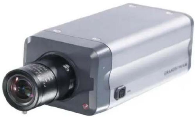
Exterior view of a silver video camera with lens and control buttons (no visible text or symbols)TABLE OF CONTENTS
GXV3651\_FHD User Manual
WELCOME 4
SAFETY COMPLIANCES 5
WARRANTY....7
PACKAGE CONTENTS 8
EQUIPMENT PACKAGE CONTENTS 8
PRODUCT OVERVIEW 9
GXV3651 FHD SIDE VIEW 9
GXV3651 FHD BACK PANEL 10
GXV3651 FHD SAMPLE CONNECTION DIAGRAM 11
GXV3651_FHD KEY FEATURES 12
GXV3651_FHD LENS SPECIFICATION 13
INSTALLATION GUIDE ....14
CONNECT YOUR GXV3651_FHD 14
CONFIGURING THE GXV3651 FHD VIA WEB BROWSER.... 15
GXV3651 FHD HOME WEB PAGE 18
GXV3651 FHD CONFIGURATION & LANGUAGE PAGE.... 19
BASIC SETTINGS EXPLANATION ....20
SYSTEM SETTINGS PAGE 20
VIDEO & AUDIO SETTING PAGE 21
CMOS SETTINGS PAGE 23
WI-FI SETTINGS PAGE 24
NETWORKING SETTING PAGE 25
DDNS SETTINGS PAGE 26
SIP SETTING PAGE 27
STATUS PAGE 29
ADVANCED SETTINGS EXPLANATION ....30
USER MANAGEMENT PAGE 30
MAINTENANCE PAGE 31
SMTP SETTING PAGE (EMAIL ALARM) 32
FTP SETTINGS PAGE (UPLOAD ALARM) 33
PTZ SETTINGS PAGE 34
CONNECT A PTZ DEVICE TO THE GXV3651_FHD 35
ALARM SERVER SETTINGS PAGE (UPLOAD ALARM TO SUPPORTED VMS OR HTTP SERVER) 36
ALARM EVENT PAGE 37
CONNECT ALARM INPUT EQUIPMENT TO THE GXV3651_FHD 38
SETUP ALARM ACTIONS....38
SETUP ALARM EVENT TIME SCHEDULE 39
HOW TO CONNECT AN ALARM OUTPUT EQUIPMENT TO GXV3651 FHD 40
MOTION DETECTION CONFIGURATION PAGE (SET ALARM).... 41
SYSLOG SETTINGS PAGE (TROUBLESHOOTING) 43
LIVE STORAGE SETTING PAGE (SD CARD FILE MANAGEMENT) 44
SOFTWARE UPGRADE......45
SOFTWARE UPGRADE VIA TTFP, HTTP OR HTTPS 45
INSTRUCTIONS FOR LOCAL FIRMWARE UPGRADE USING TFTP SERVER: 46
FIGURE 9 WI-FI NETWORKING SETTING PAGE....24
FIGURE 10 NETWORK SETTING PAGE....25
FIGURE 11 DDNS SETTING PAGE....26
FIGURE 12 SIP SETTING PAGE 27
FIGURE 13 STATUS PAGE....29
FIGURE 14 USER MANAGEMENT PAGE....30
FIGURE 15 MAINTENANCE PAGE....31
FIGURE 16 SMTP SETTING PAGE 32
FIGURE 17 FTP SETTING PAGE....33
FIGURE 18 PTZ SETTING PAGE....34
FIGURE 19 PTZ CONNECTION....35
FIGURE 20 ALARM HTTP SERVER SETTING PAGE....36
FIGURE 21 ALARM EVENT SETTING PAGE....37
FIGURE 22 ALARM OUTPUT CONNECTION....40
FIGURE 23 MOTION DETECTION CONFIGURATION PAGE 41
FIGURE 24 MOTION DETECTION SCHEDULE CONFIGURATION PAGE 42
FIGURE 25 SYSLOG CONFIGURATION PAGE 43
FIGURE 26 LIVE STORAGE MANAGEMENT PAGE 44
FIGURE 27 FIRMWARE UPGRADE AND PROVISIONING 45
FIGURE 28 FACTORY RESET FROM WEB INTERFACE....47
WELCOME
The GXV3651_FHD is a next generation IP camera for remote monitoring and surveillance over your LAN or Internet.
The GXV3651_FHD combines best in class IP video technology and SIP protocols for a robust IP surveillance solution. The product features H.264 video streams with up to 30 frames per second at 1080p resolution, delivering rich image clarity at rapid transmission rates. Integrated SIP can pass alarms to the PSTN, mobile phones, SIP IP phones, SIP videophones and enables 2-way VoIP communication.
The GXV3651_FHD ensures case of use, integration and deployment with a multilingual graphical user interface. The GXV3651_FHD can be quickly installed and connected to your network and accessed from anywhere over the internet. Grandstream's flexible video management software enables users to monitor multiple environments in one easy to use application. The intuitive web interface lets users easily access, manage, view and record live video streams from the device.
The GXV3651_FHD is a powerful solution for small to medium sized offices, homes and storage facilities looking to safeguard their valuables.
Safety Compliances
These instructions are intended to assist users with the operation of the GXV3651_FHD and also to instruct on how to avoid dangerous situations or damage to the device.
Warnings: Serious injury or death may be caused if any of the warnings below are neglected.
Cautions: Injury or damage to the equipment may occur if any of the following caution messages are neglected.

Warnings Follow these safeguards to prevent serious injury or death.

Cautions Follow these precautions to prevent potential injury or material damage.

Warnings:
Input voltage should meet both the SELV (Safety Extra Low Voltage) and the Limited Power Source with DC 12V according to the IEC60950-1 standard. Please refer to the technical specifications for more details.
Do not use a third-party power adapter or power cord
When the device is installed on the wall or ceiling, make sure that it is firmly attached.

Notice:
Make sure that the power supply voltage is correct before using the camera. Do not drop the device or expose it to physical shock.
Do not expose the device to temperatures outside the range of -30^ to +50^ . PSU and PoE mode when the device is in operation.
Do not expose the device to high electromagnetism radiation.
To avoid heat accumulation, make sure that your operating environment has proper ventilation.
Do not attempt to open, disassemble, or modify the device
A few parts (e.g. electrolytic capacitor) of the equipment shall be replaced regularly according to their average life time. The average life time varies from the differences between operating environments and usage history. Regular maintenance checks are recommended for all users. Please contact your dealer for more details.
Note:
This device complies with part 15 of the FCC Rules. Operation is subject to the following two conditions:
(1) This device may not cause harmful interference, and
(2) This device must accept any interference received, including interference that may cause undesired operation.
Changes or modifications not expressly approved by the party responsible for compliance could void the user's authority to operate the equipment.
Note: This equipment has been tested and found to comply with the limits for a Class B digital device, pursuant to part 15 of the FCC Rules. These limits are designed to provide reasonable protection against harmful interference in a residential installation. This equipment generates uses and can radiate radio frequency energy and, if not installed and used in accordance with the instructions, may cause harmful interference to radio communications. However, there is no guarantee that interference will not occur in a particular installation. If this equipment does cause harmful interference to radio or television reception, which can be determined by turning the equipment off and on, the user is encouraged to try to correct the interference by one or more of the following measures:
• Reorient or relocate the receiving antenna.
- Increase the separation between the equipment and receiver.
- Connect the equipment into an outlet on a circuit different from that to which the receiver is connected.
- Consult the dealer or an experienced radio/TV technician for help.
Warranty
If you purchased your GXV3651_FHD from a reseller, please contact the company where you purchased your device for replacement, repair or refund.
If you purchased the product directly from Grandstream, please contact your Grandstream Sales and Service Representative for a RMA (Return Materials Authorization) number before you return the product. Grandstream reserves the right to remedy warranty policy without prior notification.
Caution:
Changes or modifications to this product not expressly approved by Grandstream, or operation of this product in any way other than as detailed by this User Manual, could void your manufacturer warranty. Please do not use a different power adaptor with the GXV3651_FHD as it may cause damage to the products and void the manufacturer warranty.
- This document is subject to change without notice. The latest electronic version of this user manual is available for download at: http://www.grandstream.com/products/surveillance/gxv3651/documents/gxv3651_fhd_user_manual.pdf
Reproduction or transmittal of the entire or any part, in any form or by any means, electronic or print, for any purpose is not permitted without the express written permission of Grandstream Networks, Inc.
PACKAGE CONTENTS
Equipment Package Contents
The GXV3651_FHD package contains:
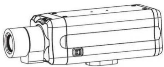
• GXV3651_FHD IP Camera
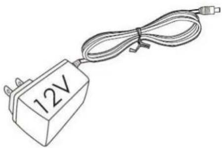
• 12V DC power Adapter
- 6-pin terminal block connector – 6-pin connector block for connecting external devices, such as infrared detector, smoke detector and etc., to Alarm IN, Alarm OUT and RS485 pins.
- Quick installation guide
natural_image
Technical line drawing of a mechanical device with cylindrical body and mounting bracket (no text or symbols)GXV-3651_FHD
natural_image
Line drawing of a 12V power supply connected to a cable (no text or symbols on the device body)Power Adapter

natural_image
Technical line drawing of a 3-pin electrical connector (no text or symbols)6-pin Terminal Block Connector

natural_image
Blank rectangular book or document with no visible text, symbols, or markingsQuick Installation Guide
PRODUCT OVERVIEW
GXV3651_FHD Side View
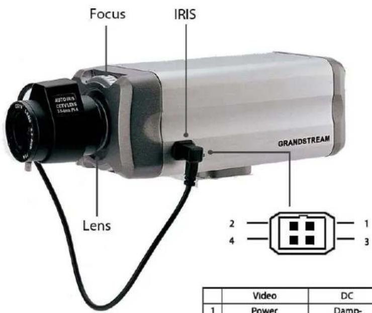
| Video | DC | |
| 1 | Power | Damp- |
| 2 | NC | Damp+ |
| 3 | Video | Driver |
| 4 | GND | Driver- |
Figure 1 Side view
Note: The above shown is an 3 ^rd party optional Auto Iris Lens (Not Supplied)
GXV3651_FHD Back Panel
Indicators and Connectors on Back Panel
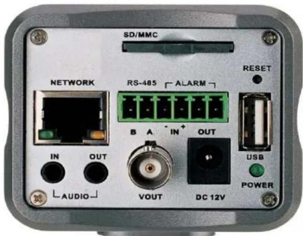
Figure 2 Back panel view
• NETWORK: 10/100 Switch LAN port for connecting to Ethernet. The indicator will be steady for connection and flashing for network activity.
• AUDIO IN: 3.5mm port for audio input devices (Microphone, pickup and etc.).
• AUDIO OUT: 3.5mm port for audio output devices (speakers, and etc.).
• VOUT: 1 BNC (Voltage: 1.0V p-p, Resistance75Ω) port for video output.
• DC 12V: 12V DC power jack; UL Certified.
• SD/MMC: SD card slot.
- RESET: Press the Reset button for 10 seconds to perform a factory reset.
• PINs: 1 PTZ connector, Alarm In connector, and Alarm out connector.
• USB: USB connector for USB flash/hard drives.
• POWER: The indicator will be solid green if the power is on.
GXV3651_FHD Sample Connection Diagram
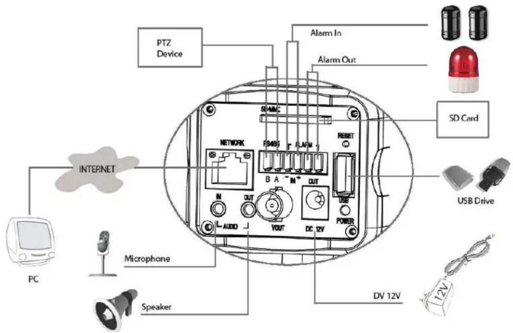
Figure 3 Connection diagram
GXV3651\_FHD Key Features
The table below lists the key features the GXV3651_FHD Supports.
Table 1: GXV3651_FHD Technical Specifications
| Image Sensor | 1/2.5", 5-Megapixel CMOS, 2592x1944 (pixels), exceptionally low noise levels and low-light sensitivity for superior video quality at very high resolution (1080p) |
| Lens Type | 1⁄2", 4.5-10mm, Manual-Iris, CS |
| Day & Night | Electronic, with integrated IR_CUT and light sensor |
| Responsitivity | 1.4V/lux-sec (550nm) |
| Video Resolution | 15fps at 2048x1536; 30fps for 1920x1080, 1600x1200, 1280x960, 1280x720, 1024x768, 800x592, 800x480, 640x480, 640x368, 480x368, 480x272, 320x240, 320x176, 256x192 and 256x144 |
| Pixel Dynamic Range | 70.1dB, with SNRMAX 38.1dB (full resolution) |
| Max Frame Rate in Max Resolution | 1920x1080 @ 30fps |
| Video Bit Rate | 32 Kbps - 8 Mbps, multi rate for preview and recording |
| Audio Input | LINE-IN, built in microphone |
| Audio Output | LINE-OUT |
| Audio Compression | G.711 U/A, AAC |
| IRIS Control | Manual IRIS (default lens), optional auto-iris lens |
| Alarm Input | Vin≤45V, lin≤35mA, Normal open |
| Alarm Output | 125VAC/0.5A,30VDC/2A, Normal open |
| Embedded Analytics | Motion detection (up to 16 regions),video loss (pending) |
| Video Management System | ONVIF compliant, HTTP API for advanced integration |
| Pre-/post-alarm Buffer | 24MB |
| Pre-/post-alarm triggered record | Pre-30s and post-60s recording@2Mbps; Pre-50s and post-100s recording@1Mbps |
| Snapshots | Triggered upon events, send via email/FTP, or stored in local SD card |
| Multi-streaming Preview & Recording | Yes |
| ePTZ | Yes (at 320x240 resolution) |
| Security | Login password, access privilege management |
| Peripheral Ports | Internal SDHC 2.0 socket, USB 2.0 |
| Network Port | 10M/100M auto-sensing, RJ45 |
| Network Protocol | TCP/UDP/IP, RTP, RTSP, DHCP, DDNS, HTTP/HTTPS, SMTP, FTP, NTP, PPPoE |
| Power over Ethernet (PoE) | IEEE 802.3af default class |
| SIP/VolP Support | Yes, Voice & Video-over-IP |
| Dimensions (W x H x L) | 152mm x 68mm x 64mm (Lens not included) |
| Weight | 0.51kg (lens not included) |
| Temperature / Humidity | 0°C - 45°C (32°F-113°F) Humidity 10-90% RH (non-condensing) |
| Power Adapter | Output: 12VDC/1A; Input: 100-240VAC, 50-60Hz |
| Regulatory Compliance | FCC Part 15, Subpart B Class B; CE EN 55022 Class B, EN 61000-3-2, EN 61000-3-3, EN 55024, EN 60950-1; C-tick AS/NZS CISPR 22, CISPR 24 |
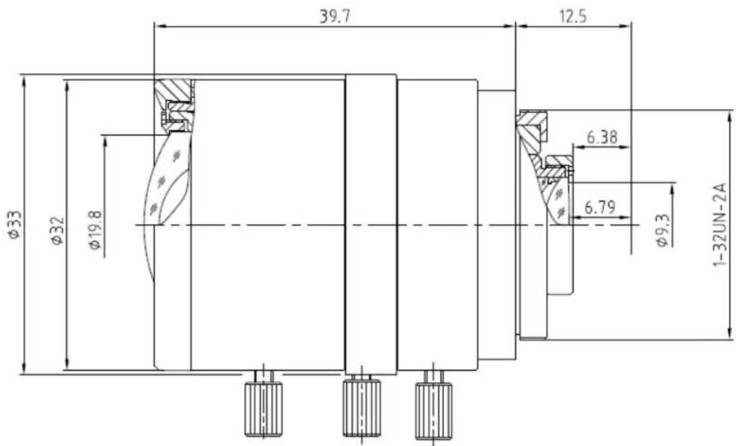
GXV3651_FHD Lens Specification
| Parameters GXV3651_FHD | |
| Lens Format 1/2” | |
| Image Sensor | 1/2.5” CMOS |
| Focal Length | 4.5mm – 10mm |
| Aperture Ratio F1.6 | |
| View Angle | D:102°- 46.5°H: 80.5°-37°V: 60°-28° |
| IRIS Manual | |
| Minimum Object Distance | 10 cm |
| IR CUT Filter Yes | |
INSTALLATION GUIDE
Minimum Recommended System Requirement
To install GXV3651_FHD, you have to have a computer, PC recommend. The minimum recommended PC system requirement listed below:
- Windows 2000, XP, Windows Vista, Windows 7 (32bit or 64bit)
• CPU: Intel Pentium 4 or higher, 2 GHz
• RAM: 1 GB (4 GB recommended for larger systems)
• Support for DirectX 8.0 and above.
Connect your GXV3651\_FHD
Using the Power adapter as power supply
- Connect an RJ-45 cable to the NETWORK port of the GXV3651 FHD.
- Connect the other end of the RJ-45 cable to your network or PC.
- Connect the power supply to the DC 12V connector block inside the GXV3651 FHD.
- Connect the other end of the power supply to a wall outlet. The POWER LED will turn solid green.
Using PoE as power supply:
- Connect an RJ-45 to the NETWORK port of the GXV3651 FHD.
- Connect the other end of the RJ-45 cable to a PoE switch. The POWER indicator will turn solid green.
NOTE:
If you are going to connect the device to a hub/switch/router, please use a straight-through cable. A crossover cable will be used if you are going to connect the device directly to a PC.
Configuring the GXV3651\_FHD via Web Browser
The GXV3651_FHD's embedded Web server responds to HTTP/HTTPS GET/POST requests. Embedded HTML pages allow you to configure your IP camera through Microsoft Internet Explorer.
Access the GXV3651\_FHD Web Configuration Menu
Connect the Camera to a DHCP server.
The GXV3651_FHD by default enabled as DHCP client, it will automatically get IP address from the network with DHCP server running. User can know the IP address assigned to the camera from DHCP server log or using Grandstream free GS_Search tool.
- Download the GS Search tool from Grandstream website:
http://www.grandstream.com/products/tools/surveillance/gs_search.zip
-
Run the Grandstream GS_Search tool by double click the unzipped "GS_Search.exe".
-
Click on Search button to begin device detection
-
The detected devices will appear in the Output field like below
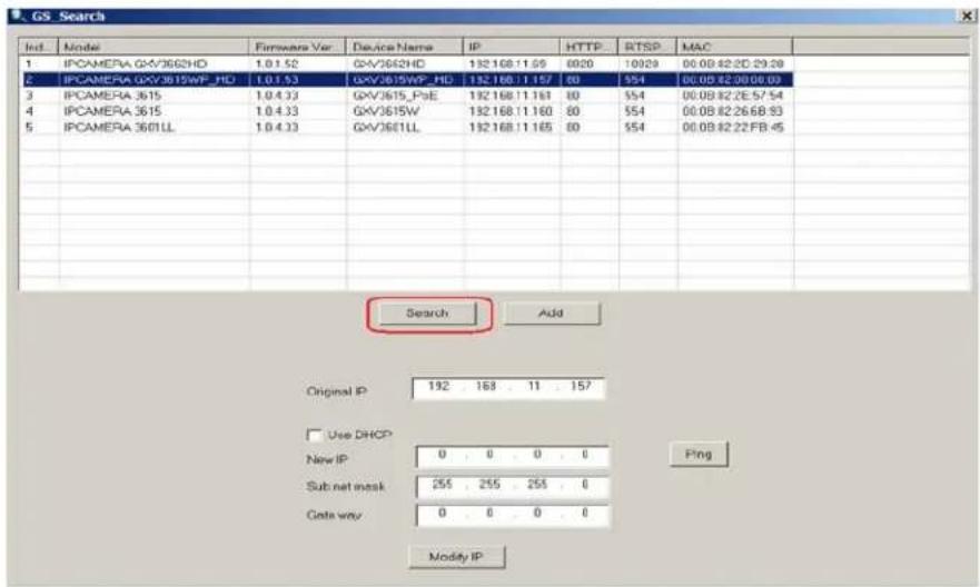
- Double click the column of the detected camera, the browser will automatically open and link to the device IP and the web configuration page.
- The browser will ask for plug-in or ActiveX if not installed, otherwise it will get to Home page and start to show the video captured by the camera (by default the camera enabled anonymous access)
- Click "Configuration", the browser will ask credentials to authorize configuration.
- Enter the administrator user name and password to access the Web Configuration Interface, the default user name and password are both set to admin.
-
In step 6, IE will indicate that "This website wants to install the following add-on: GSViewerX.cab from Grandstream Networks Inc.", allow the installation.
-
Firefox user need to download and install the plug-in to see the video, the plug-in for Firefox is here: http://www.grandstream.com/products/tools/surveillance/firefox_plugin.exe
NOTE:
Please temporarily disable Antivirus or Internet Security Software when download and install the Grandstream Firefox plug-in for video or "GSViewerX.cab" for Microsoft Internet Explorer.
Connect to the Camera using Static IP
If no DHCP server in the network or the camera does not get IP from DHCP server, user can connect the camera to a computer via cross-over cable, using static IP to configure the camera.
The default IP, if no DHCP server; or DHCP offer time out (3 minutes), is 192.168.1.168
- Connect the computer via cross-over Ethernet cable directly to the IP camera GXV3651 FHD
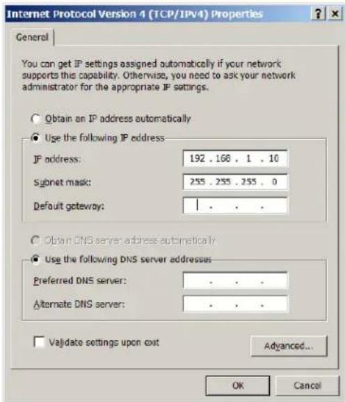
- Configure the computer using Static IP: 192.168.1.XXX (1<XXX<255, but NOT 168) and configure the "Subnet mask" to "255.255.255.0". Leave the "Default Gateway" to "Blank" like below:
-
Power on the GXV3651 FHD.
-
Start the IE or Firefox browser when the network connection is up.
-
Enter 192.168.1.168 in the address bar of the browser.
-
The browser will ask for plug-in or ActiveX if not installed, otherwise it will get to Home page and start to show the video captured by the camera (by default the camera enabled anonymous access)
-
Click "Configuration", the browser will ask credentials to authorize configuration.
-
Enter the administrator user name and password to access the Web Configuration Interface, the default user name and password are both set to admin.
- In step 6, IE will indicate that "This website wants to install the following add-on: GSViewerX.cab from Grandstream Networks Inc.", allow the installation.
- Firefox user need to download and install the plug-in to see the video, the plug-in for Firefox is here: http://www.grandstream.com/products/tools/surveillance/firefox_plugin.exe
NOTE:
➢ Please temporarily disable Antivirus or Internet Security Software when download and install the Grandstream Firefox plug-in for video or "GSViewerX.cab" for Microsoft Internet Explorer.
GXV3651\_FHD Home Web Page
The Home Page of GXV3651_FHD shown as Figure 4:
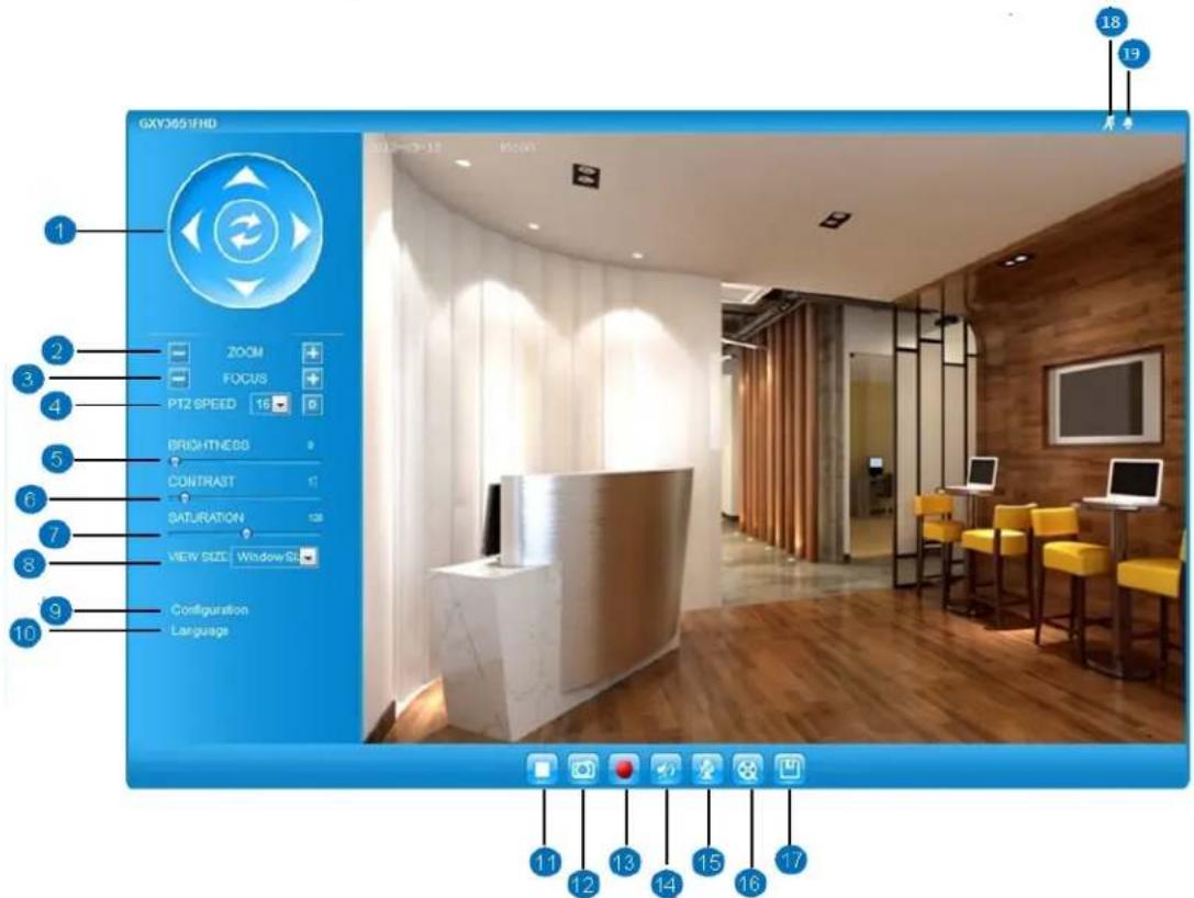
Figure 4 Home Page of GXV3651_FHD
- Control Console: PTZ Console controller for ePTZ function.
- ZOOM: Zoom in or Zoom out during ePTZ operation.
- FOCUS: Adjust the focus of image (if equipped with the proper lens).
- PTZ SPEED/Default Button: Adjust the rotate speed of the control console;
Default button to reset the video brightness, contrast and saturation to factory default value. - BRIGHTNESS: Adjust the image brightness.
- CONTRAST: Adjust the image contrast.
- SATURATION: Adjust the image saturation
- View Size: Adjust the image display size.
- Configuration: Click to enter "Configuration Page" to configure the parameters of GXV3651_FHD (Administration privilege required).
- Language: Click to switch webpage language.
(Current supported: Chinese, English and Russian) - Play/Stop: Start/Stop Play the video stream in webpage.
- Snapshot: Click to capture and save a snapshot of current video displayed.
Default directory: C:\GS_Capture -
Record: Click to Start/Stop record of current video into a file.
Default directory: C:\GS_Record -
Sound On/Off:
-
Talk:
-
Replay:
-
Record File Path:
-
Motion Detection Alarm Indicator:
-
DI Alarm:
Toggle to listen/stop the sound from camera
Toggle to talk to camera speaker. (PC microphone required)
Click to playback the recorded video file.
Click to adjust the file path of saved video files.
If motion detection alarm triggered, the indicator will flash in red.
Click the indicator icon to turn off the alarm indication.
If alarm in triggered, the indicator will flash in red.
Click the indicator icon to turn off the alarm indication.
GXV3651\_FHD Configuration & Language Page
- When click the "Configuration" tab, web page will link to page to configure the related parameters of the GXV3651_FHD.
- There are two big categories of settings: Basic Settings and Advanced Settings. Details will be illustrated in the later Chapter.
When click the "Language" tab, supported languages will be displayed as shown below. Click to select the related webpage display language.
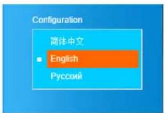
- Currently firmware only support: English (default), Simplified Chinese and Russian.
BASIC SETTINGS EXPLANATION
System Settings Page
This page allow user to configure the system settings of GXV3651_FHD.
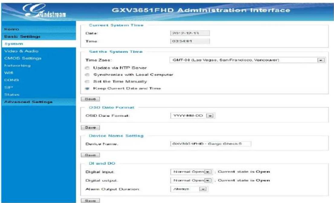
Figure 5 System Settings Page
- Current System Time: Display time current system is running at
- Set the System Time: Configure the time system is running.
○ Time Zone:
○ Self-Defined Time Zone:
○ Update via NTP Server:
○ Synchronize with
Local Computer: Synchronize time with local computer
- Set the Time Manually: Manually input the time
- Keep Current D/T: Select to use camera current displayed time
- OSD Date Format: Pull down to select date format displayed on video screen.
• Device Setting: Setting of Device Operation
o Device Name:
The name of device which will be shown in the result of GS_Search program.
• DI and DO Setting: Setting the state of the Alarm IN / Alarm out Settings
NOTE:
(*) If select this option, a valid DNS server must be configured under Basic Settings → Networking
Save button has to be clicked to save all the changes made to the device.
Video & Audio Setting Page
This page allows user to configure the video and audio related settings.
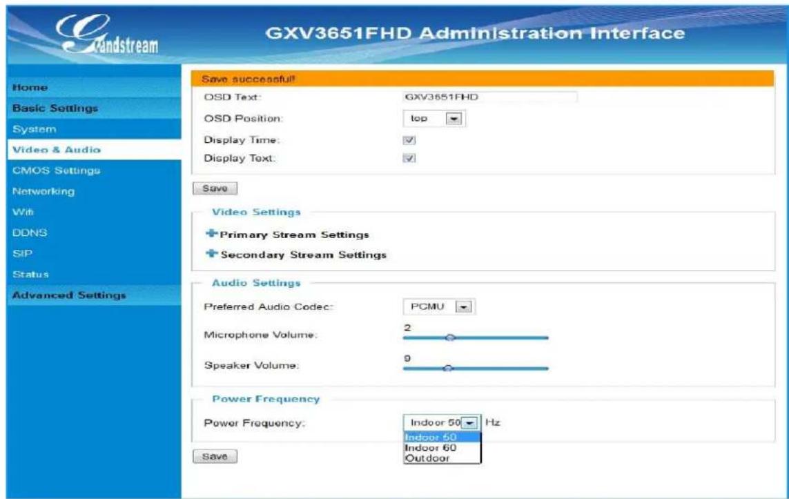
Figure 6 Video & Audio Settings Page
- On Screen Display (OSD): Display time stamp and text on the video screen.
- OSD Text: Inputted text (to identify the camera) shown on the screen.
- OSD Position: Show the OSD in either top or bottom position on screen.
o Display Time: When checked, time stamp will display on video screen
o Display Text: When checked, inputted text will display on video screen.
- Audio Settings: Pull down to disable or select different audio codec used in microphone. Three codec supported: G.711u, G.711a and AAC.
o Microphone Volume: Slide to adjust microphone gain.
o Speaker Volume: Slide to adjust the speaker volume.
• Power Frequency: Select correct local power frequency to avoid video flicking effect under fluorescence light condition.
Video Settings
Primary Stream Settings
Preferred Video Codec:
H264
Resolution:
2048^1536 (4:3)
Bit Rate:
1024 kbps
Maximum Frame Rate:
15 fps
Bit Rate Control:
CBR VBR
Image Quality:
Normal
I-frame Interval:
30 Frame(1-100)
Secondary Stream Settings
Preferred Video Codec:
MJPEG
Resolution:
320*240 (4:3)
Bit Rate.
256 kbps
Maximum Frame Rate
5 fps
Bit Rate Control:
CBR VBR
I-frame Interval:
30 Frame(1-100)
Figure 7 Video & Audio Settings Page
• Primary Stream Settings:
o Preferred Video Codec: H.264 supported.
o Resolution: The video resolution in pixel used in camera video
o Bit Rate: video bit rate used in video
o I-frame Interval: I-frame interval
• Secondary Stream Settings:
Pull down to select, same as Primary steam.
NOTE:
H.264 suggested if camera needs to be viewed via Internet.
If MJPEG selected, reduce fps to minimum to save bandwidth and get better image
Grandstream IP Camera provides two video streams; user can use them with flexibility. For example, the high-resolution stream for local recording; another low or high resolution for remote monitoring; or vice versa depending application scenarios.
Use below link to calculate bandwidth and storage before installation http://www.grandstream.com/support/tools/bandwidth-storage-calc
CMOS Settings Page
This page allows user to adjust the CMOS parameters:
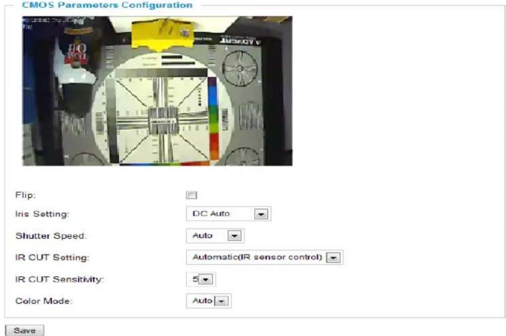
Figure 8 CMOS Settings Page
- Flip: Check this will allow video flip 180^ vertically in horizontal axis.
- Iris Setting: Select from either automatic, where the iris would open or close depending on the environment conditions, or set it to manual where the user can select from having it open100/80/60/40/20 percent.
- Shutter Speed: Select from either automatic shutter speed depending on the environment conditions, or select one of the available shutter speeds from 1/30 to 1/1000 of a second.
- IR CUT Setting: Select from either manual or automatic. If the user selects manual then select from either daytime mode or night mode. If the user selects automatic, then select a sensitivity value from 1 to 5 that adjusts the best to the environment conditions.
• Color Mode: Camera Color Mode. There are three options: Color; Black/White; Auto.
NOTE:
➢ Flip option recommended if camera requires ceiling installation
➢ Auto option recommended for both Shutter Speed and Color Mode.
Wi-Fi Settings Page
This page allows user to configure Wi-Fi network related parameters. Grandstream Wi-Fi dongle is required for this to work. Wi-Fi dongle and USB flash drive storage is mutual exclusive and only one choice will work at a time.
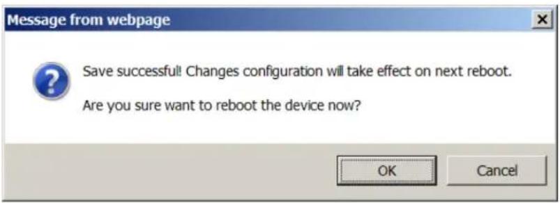
Figure 7-1: Wi-Fi Networking Setting Page
- Enable Wi-Fi: If checked and click "Save", a reboot is required before Wi-Fi start to work. A pop up window will show as Figure 7-1.
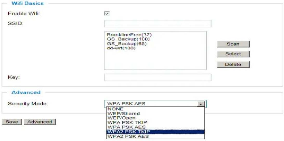
Figure 9 Wi-Fi Networking Setting Page
- SSID: Wi-Fi network SSID. When Wi-Fi enabled, click "Scan" the camera will scan the Wi-Fi access point nearby.
• Key: _ Key for security enhanced Wi-Fi network the camera try joining.
• Security Mode: The security mode Wi-Fi access point or router used.
Networking Setting Page
This page allows user to configure network related parameters:
IP Address Configuration
Dynamically Assigned via DHCP
- Statically Configured as:
| IP Address: | 192.168.50.144 |
| Subnet Mask: | 255.255.255.0 |
| Default Gateway: | 192.168.50.1 |
DNS Configuration
Obtain DNS Server Address Automatically
- Use the Following DNS Server Address:
| Primary DNS Server: | 8.8.8.8 |
| Secondary DNS Server: | 8.8.4.4 |
HTTP
HTTP Port: 80
Save
PPPoE
| PPPoE Account ID: | pppos_login |
| PPPoE Password: |
Save
Figure 10 Network Setting Page
• IP Address Configuration: Camera IP address configuration
○ Dynamically Associated via DHCP: camera.
Default setting, DHCP server assign IP to
o Statically Configured as:
Static IP address configuration
• DNS Configuration: DNS server IP must be configured correctly if using static IP.
- HTTP: Web access TCP port, default 80.
- PPPoE: Set the PPPoE credentials if you intended to use PPPoE.
NOTE:
If camera behind SOHO router with port forwarding configuration for remote access, static IP or static DHCP has to be used to avoid IP address change after router reboot.
TCP port above 5000 suggested if port forwarding HTTP remote access, due to some ISP would block port 80 inbound traffic. For example, change the default HTTP port from 80 to 8088, to make sure the port forwarding not likely be blocked.
In addition to HTTP port, RTSP port also required to be configured for port forwarding, in order for remote party viewing the H.264 video.
If change the default port from TCP 80 to port "A", then RTSP port should be "2000+A". Both TCP port "A" and "2000+A" should be configured for port forwarding in the router. For example, the HTTP port changed to 8088, the RTSP port should be 10088, both 8088 and 10088 should be configured for port forwarding in order for remote camera video access.
DDNS Settings Page
This page allows user to configure dynamic DNS related parameters:
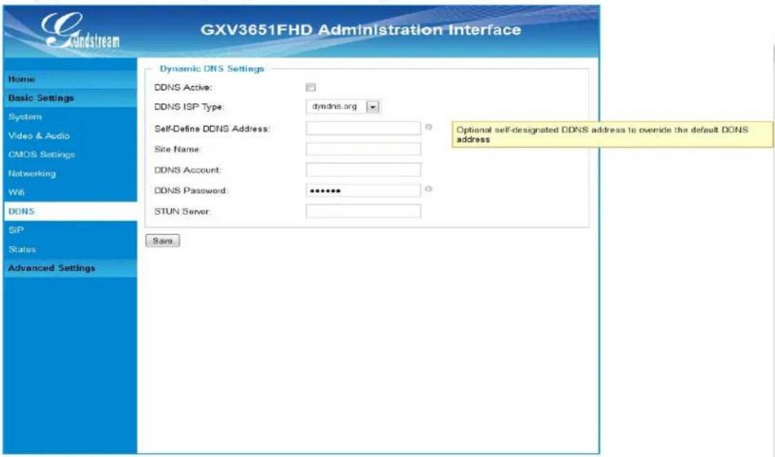
Figure 11 DDNS Setting Page
- DDNS Active: Enable DDNS by check this field.
- DDNS ISP Type: Select the DDNS service provider from the pull-down menu list
• Self-Define DDNS Address: Input the self-defined DDNS address - Site Name: DDNS site name
• DDNS Account: DDNS account name
• DDNS Password: DDNS password - STUN Server: STUN server FQDN or IP. If device behind non-symmetric router STUN server can help to penetrate & resolve NAT issue.
SIP Setting Page
This page allows user to configure SIP related parameters.
GXV3651_FHD can be configured as SIP endpoint to call out when alarm triggered; or allow permitted number to call in to check the video if Grandstream video IP phone is used.
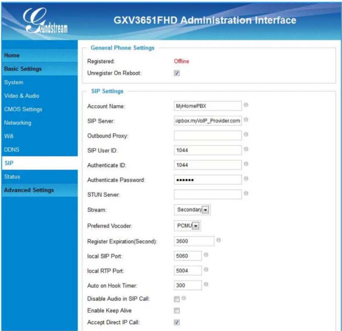
Figure 12 SIP Setting Page
- Registered: SIP registration status. Display "Online" in Green, "Offline" in Red.
- Unregistered on Reboot: If checked and server support, reboot camera will unbind all registration in same SIP account.
• Account Name: SIP account name - SIP Server: FQDN or IP of SIP server from VoIP service provider
- Outbound Proxy: IP or FQDN of Outbound proxy server, helps penetrate NAT/Firewall
- SIP User ID: SIP username, or telephone number from ITSP
• Authenticate ID: Authenticate ID used by SIP proxy
• Authenticate Password: Authenticate password used by SIP proxy
• STUN Server: STUN server used to resolve NAT if have
- Steam: Which stream used for SIP call.
• Preferred Vocoder: Audio codec used for SIP call
- Registration Expiration: Registration expiration time, default 3600 seconds
- Local SIP Port: Local SIP port, default 5060
- Local RTP Port: Local RTP port for media, default 5004
• Auto on hook Timer: Auto On Hook timer, default 300 seconds
- Disable Audio in SIP Call: Checked to disable audio for SIP call
- Enable Keep Alive: Checked to enable, help NAT resolution
- Accept Direct IP Call: Check to accept peer to peer IP call.
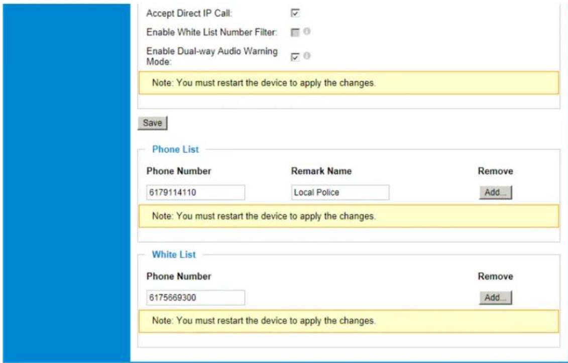
- Enable White List Number Filter: Check to allow only white list number to call in, for security
- Enable Dual-way Audio Warning: Check to enable two-way audio warning.
• Phone List/Phone Number: Callee or call receiver number when alarm call triggered. - White List/Phone Number: Phone numbers allowed to call into the camera.
Status Page
This page shows the GXV3651_FHD operation status:
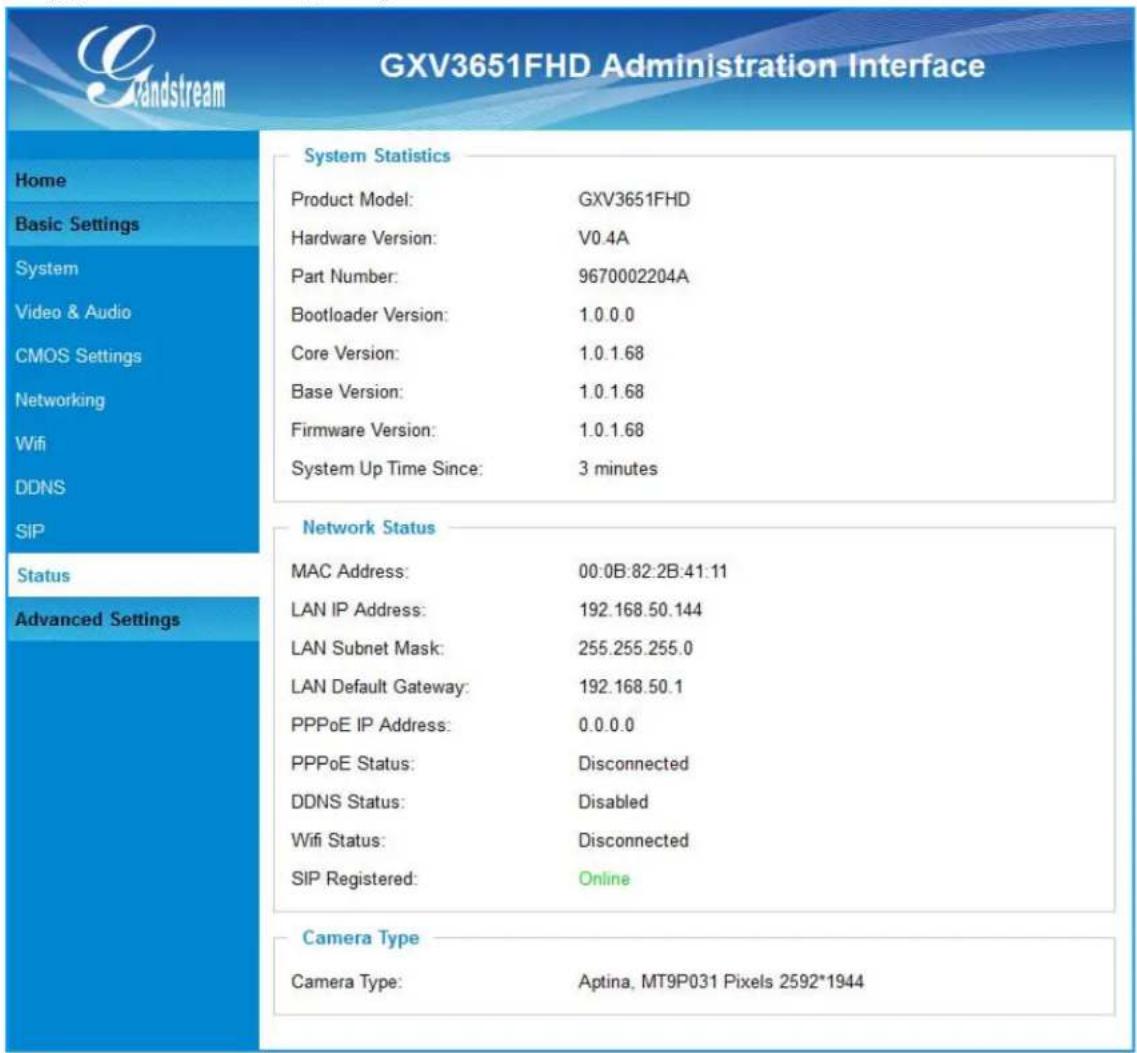
Figure 13 Status Page
NOTE:
When SIP account registered, the status will display "Online" in Green.
When SIP account unregistered, the status will display "Offline" in Red, as below.
SIP Registered:
Offline
ADVANCED SETTINGS EXPLANATION
The supports all the traditional and advanced telephony features.
User Management Page
This page allows user to do user management:
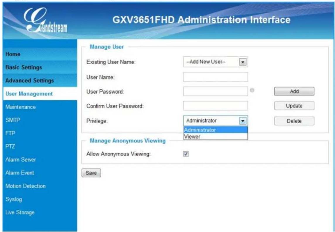
Figure 14 User Management Page
- Existing User Name: Allow revise existing user or add new user
- User Name: The name of user need to be revised
- User Password: New password if revise password
- Confirm User Password: Re-enter the new password for verification
• Privilege: Choose user privilege
- Allow Anonymous Viewing: When checked, no security enhanced. Any person can view the camera if knowing the IP or FQDN of the camera, but can NOT
change anything, just view ONLY.
Maintenance Page
This page allows user to maintain the camera:
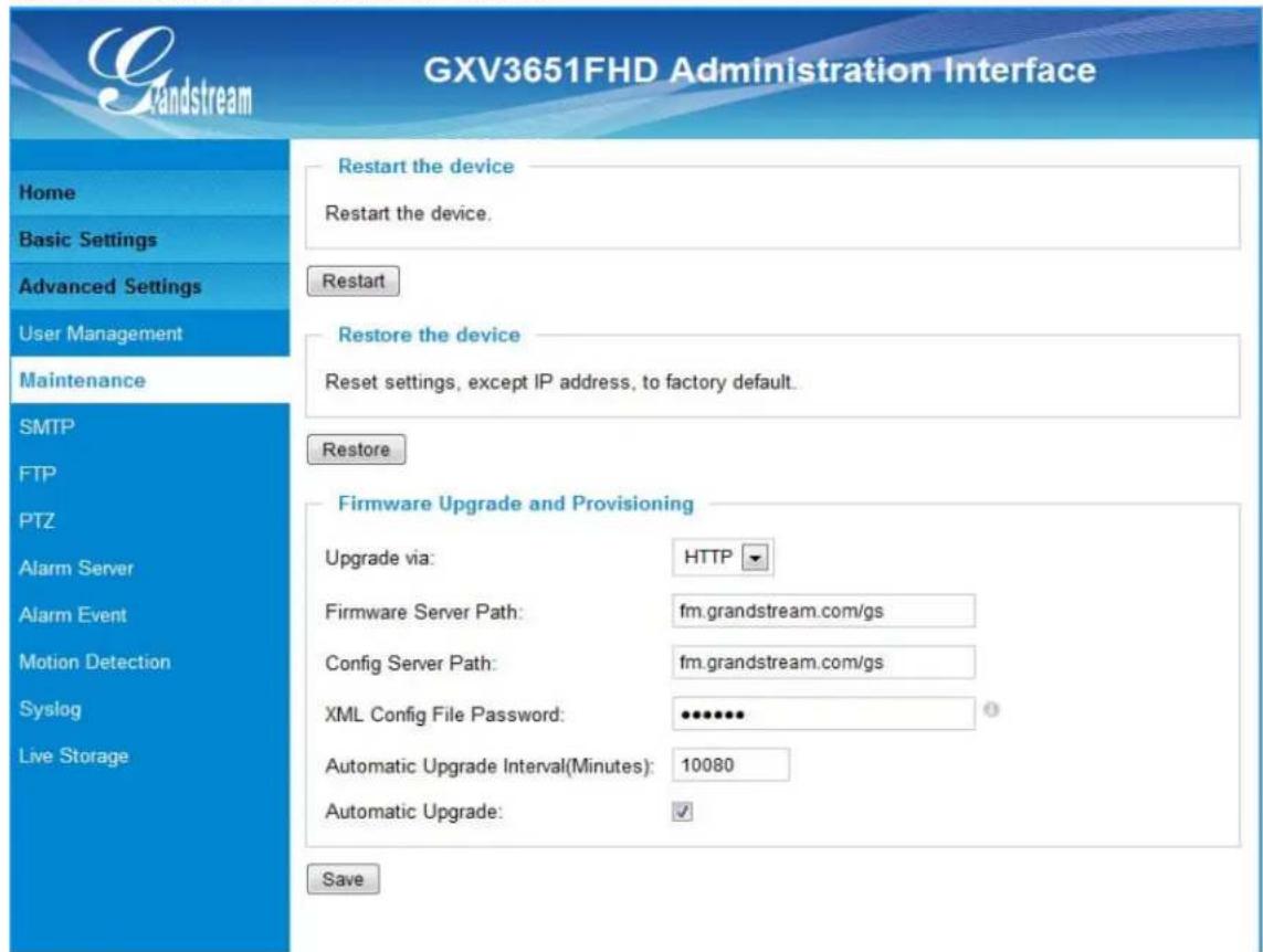
Figure 15 Maintenance Page
- Restart: When clicked, the camera will reboot or restart
- Restore: When clicked, the camera will be reset to factory default, wiping out all the configurations (except IP address)
Firmware Upgrade and Provisioning:
- Upgrade via: Upgrade firmware via TFTP, HTTP or HTTPS
- Firmware Server Path: Server path holding the firmware
- Config Server Path: Server path holding the configuration file (auto provisioning)
- XML ConfigFile Password: Password for encrypt the XML based configuration file
• Automatic Upgrade Interval (Minutes): Time interval for automatic upgrade, default 10080
• Automatic Upgrade: Checked to enable automatic firmware upgrade and provisioning.
NOTE:
Only XML based automatic provisioning is supported by GXV3651_FHD.
SMTP Setting Page (Email Alarm)
This page allows user to configure email client to send out email when alarm triggered:
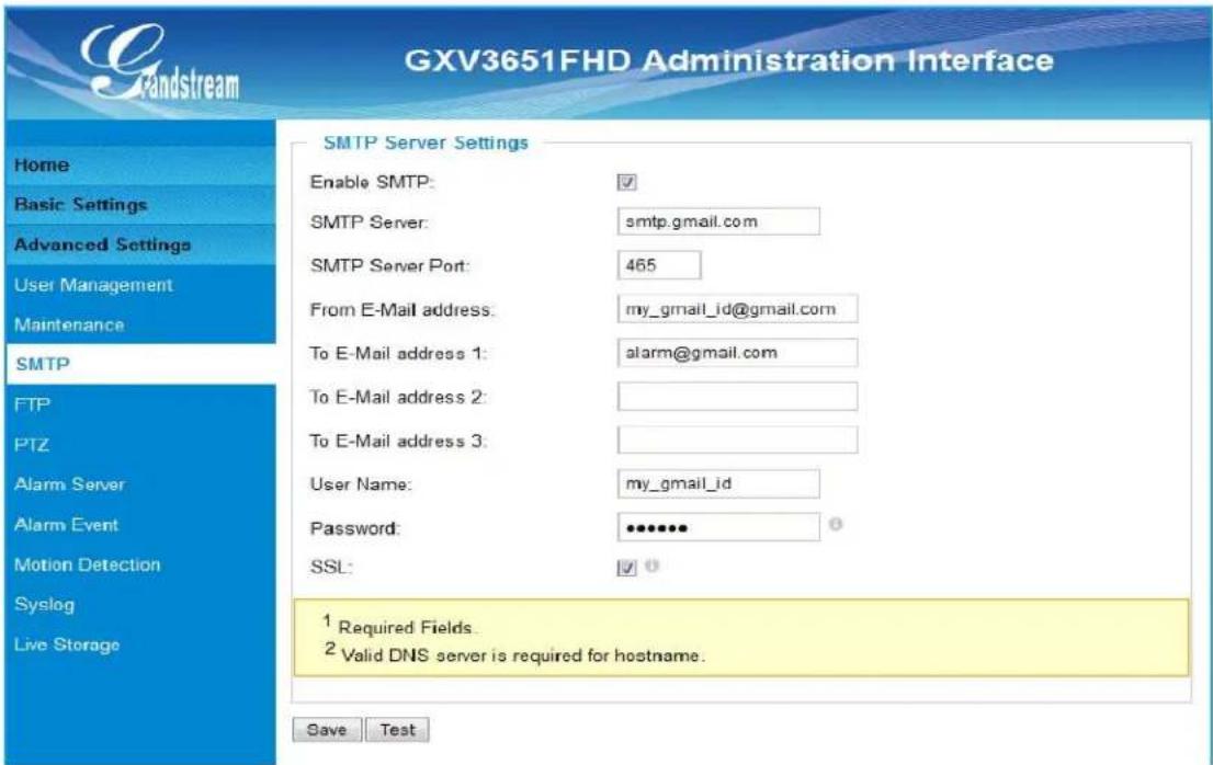
Figure 16 SMTP Setting Page
- Enable SMTP: When checked, email client is enabled.
- SMTP Server: SMTP Email Server IP or Domain Name
- SMTP Server Port: Port number used by server to send email
• From Email address: The email address of alarm email sending from, usually client email ID
• To E-Mail address: The email address to receive the alarmed email, total 3 included. - User Name: Email client User ID
- Password: Email client password
- SSL: Check if the SMTP email server requires SSL
NOTE:
➢ Click “Save” to save the email configuration information.
Click "Test" after configuration, if setting is correct, a test email will send out and "Test successful!" yellow bar will display like below

FTP Settings Page (Upload Alarm)
This page allows user to configure FTP parameters to upload the alarm or video recording:
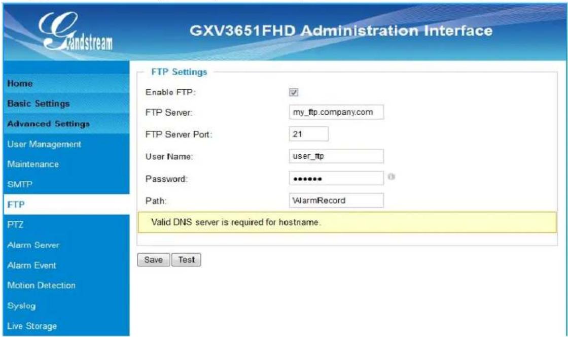
Figure 17 FTP Setting Page
- Enable FTP: When checked, built-in FTP client is enabled.
- FTP Server: IP or Domain name of FTP site or server
- FTP Server Port: TCP port for FTP server, default port number 21
- User Name: FTP server User ID
- Password: FTP server user password
• Path: Path in the server where upload files are stored.
NOTE:
➢ Click "Save" to save the FTP configuration information.
Click "Test" after configuration, if setting is correct, a test FTP operation will be performed and "Test successful!" yellow bar will display if the operation is successful.
PTZ Settings Page
This page configures the PTZ settings.
Select the PTZ protocol that your connected compatible 3^rd party equipment (e.g.: External PTZ Enclosure) by clicking on the radio in front of the protocol. Next, select the Baud Rate from the drop down menu based on technical document of the 3^rd party equipment and synchronize the Baud Rate setting.
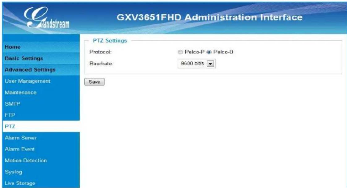
Figure 18 PTZ Setting Page
- PTZ Protocol:
The GXV3651_FHD supports both Pelco-D and Pelco-P. Select the protocol based on the technical document of your 3^rd party PTZ equipment.
- PTZ Baud Rate:
The Baud Rate is the number of distinct symbol changes (signaling events) made to the transmission medium per second in a digitally modulated signal or a line code.
Connect a PTZ device to the GXV3651\_FHD
- Connect the PTZ device (e.g.: 3^rd party external enclosure) to GXV3651_FHD by following the connection diagram shown below
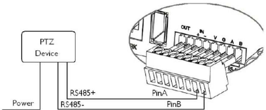
Figure 19 PTZ Connection
-
Click Advanced Settings > PTZ; in PTZ page, configure the PTZ Protocol and Baud Rate according to the technical document of your connected 3^rd party PTZ device.
-
Click Save and reboot the device to apply all the changes.
Alarm Server Settings Page (Upload Alarm to Supported VMS or HTTP Server)
This page allows user to configure alarm HTTP server to upload alarms:
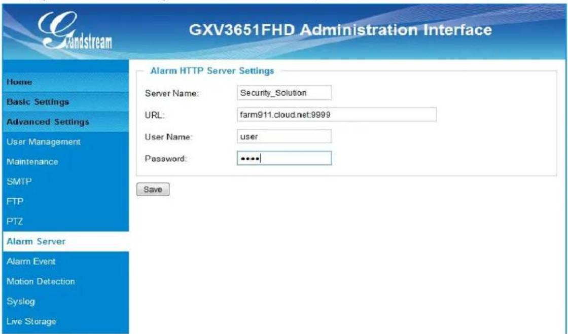
Figure 20 Alarm HTTP Server Setting Page
- Server Name:
- URL:
- User Name:
- Password:
The name of HTTP server or VMS system
U R L o f t h
User ID from that Server
Password for that User ID
NOTE:
Grandstream provide HTTP API to help 3 ^rd party company by using HTTP server or VMS to develop further solutions for its customers.
Grandstream IP Camera and DVS (include GXV3651_FHD) are ONVIF certified.
Alarm Event Page
The GXV3651_FHD supports alarm inputs, for example, infrared detector, smoke detector and so on. Follow the steps to make Alarm Input work:
- Connect the alarm input equipment to the GXV3651_FHD.
- Set up the alarm event time schedule.
- Configure the alarm actions which you would like the GXV3651_FHD to take when the alarm is triggered.
This page allows user to configure alarm event:
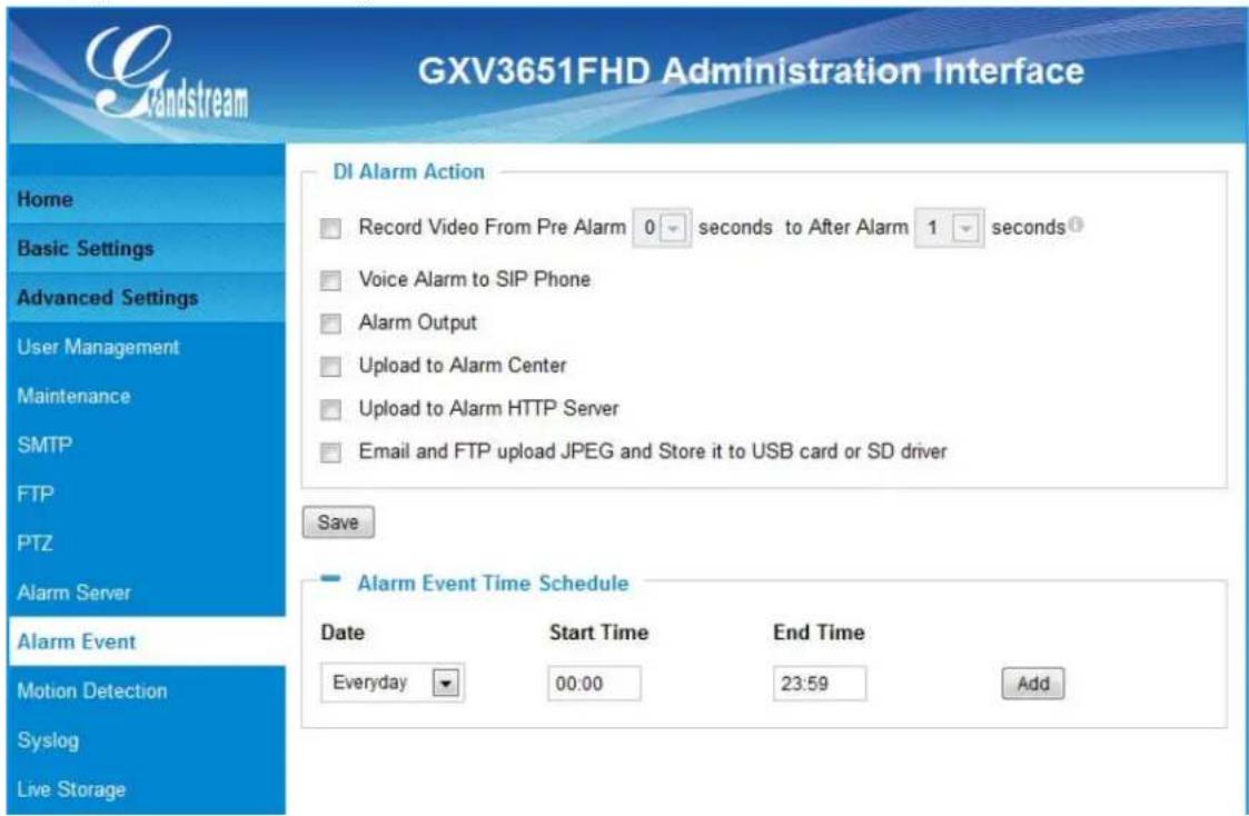
Figure 21 Alarm Event Setting Page
How Alarm Input and Alarm Output Work
Alarm-in is the alarm input port; users are able to connect sensors such as infrared sensor (PIR), smoke sensor or light sensor to it. The detectable signal voltage range for alarm-in is from 1.8V to 15 V
NOTE:
➢ Please do not connect a device that has a signal voltage that is higher than 15V, this will damage the IP camera.
Internally, the Alarm-out uses relays as a switch (30VAC/2A); users can connect devices such as an alarm siren, alert lights or electric strike to this port. Under normal circumstances, the circuit is open. When there is an alarm event, the GXV3651_FHD will close the circuit to trigger the alarm.
Connect Alarm Input Equipment to the GXV3651\_FHD
Here are two sample connection diagrams. Connect the alarm equipment to the GXV3651_FHD by following the diagram below:
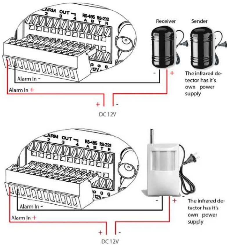
Setup Alarm Actions
An alarm action is what the GXV3651_FHD is going to do when an alarm is triggered during the defined time period – the time schedule. The GXV3651_FHD allows multiple alarm actions.
- Record Video: If this option is selected, the GXV3651_FHD will record the video when an alarm is triggered. You can enter the length of the video recording (in seconds). You can also choose the storage method for video files: SD card, USB Flash drive, or USB hard drive.
- Voice Alarm to SIP Phone: If this option is selected, the GXV3651_FHD will make calls to the number listed in the Phone List page using the configured SIP account when an alarm is triggered. To use this function, the settings in SIP page must be configured properly.
- Alarm Output: If this option is selected, the alarm will output via the configured method/equipment when it is triggered.
- Upload to Alarm Center: This option is an integrated feature with GSurf. If this option is checked, the GXV3601 will report the alarm event to GSurf.
- Upload to Alarm HTTP Server: This option is used when the Alarm Server is configured, the GXV-3651_FHD will send an HTTP GET request to the pre-configured HTTP Server.
- Email and FTP upload JPEG and Store it to USB card or SD driver :
If this option is selected, the GXV3651_FHD will capture the image and store it to connected live storage device when an alarm is triggered.
Setup Alarm Event Time Schedule
This section allows you to configure the time during which the GXV3651_FHD will monitor the
Alarm Input. The GXV3651_FHD not only can monitor your settings but also can take actions when the alarm is triggered.
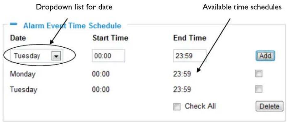
To add a schedule, select the date from the dropdown list, Start Time and End time and Click Add to add a new time schedule.
To delete a schedule, check the schedule you would like to remove and click Delete.
How to connect an Alarm Output Equipment to GXV3651\_FHD
Here is a sample connection diagram. Connect the alarm output equipment to the GXV3651_FHD by following the diagram below.
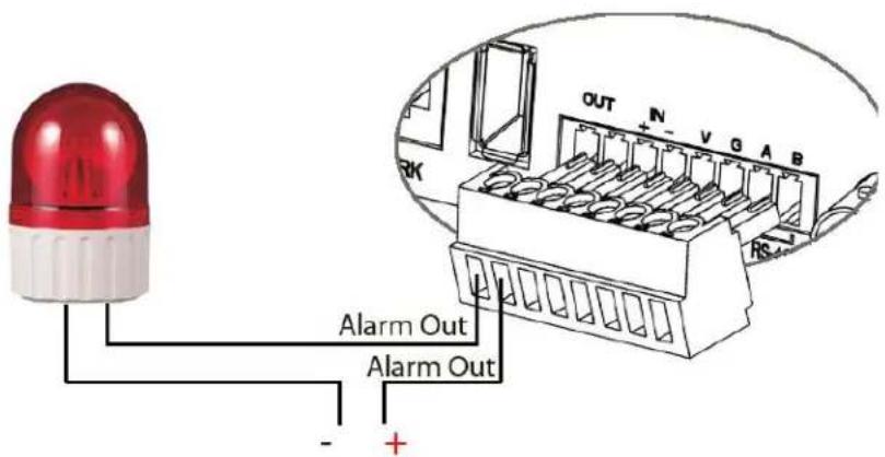
Figure 22 Alarm Output connection
Motion Detection Configuration Page (Set Alarm)
This page allows user to configure motion detection to trigger alarms:
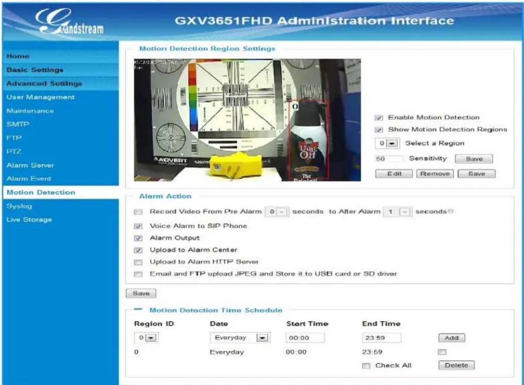
Figure 23 Motion Detection Configuration Page
- Enable Motion Detection: When checked, Motion Detection enabled.
- Show Motion Detection Regions: When checked, Motion Detection region with number will be displayed in White Rectangle in the screen; when "Edit" clicked,
the Rectangle will become Red, as shown in Figure 23.
- Select a Region: Pull down to select and configure alarm region, altogether 16 alarm region available, from 0 to 15.
- Sensitivity: Select configured alarm region number, input number for sensitivity to trigger alarm, 100 is the maximum sensible value.
Alarm Action:
- Record Video From..... Allow user to select how long pre/after Alarm trigger moment, the video be captured.
• Voice Alarm to SIP Phone: When checked, a SIP alarm phone call will be made to pre-configured number. - Upload to Alarm Center: When checked, the alarm video will be transferred to Alarm Center, like Grandstream free GSurf VMS software.
NOTE:
Grandstream free GSurf VMS software can be downloaded here:
http://www.grandstream.com/products/tools/surveillance/GSurf.exe
- Upload to Alarm HTTP Server:
When checked, alarm will be transferred to the HTTP server via HTTP API.
• Record Video and Upload to FTP Server:
When checked, the alarm will be recorded and FTP to pre-configured FTP server.
- Email and FTP upload JPEG and Store it to SD driver:
When checked, a snapshot of trigger moment will be generated and email to pre-configured email account, also save to the SD card in the SD card slot. (SD card not provided).
NOTE:
➢ Email/Snapshot storage is mutual exclusive with SD card DVS recording in next section.
This page allows user to configure Motion Detection Operation Schedule:
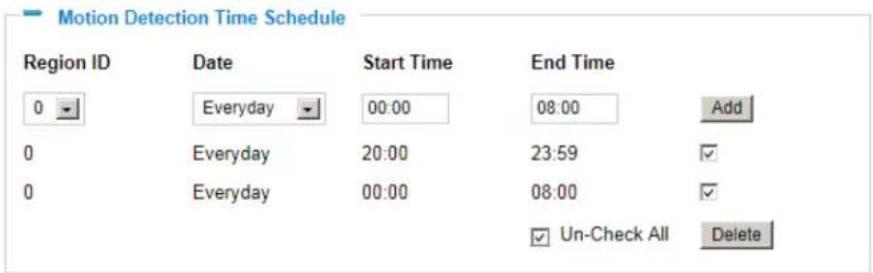
Figure 24 Motion Detection Schedule Configuration page
- As shown in Figure 24, user can configure the Motion Detection Region with related Start and Stop time to control the motion detection operation.
Syslog Settings Page (Troubleshooting)
This page allows user to enable the Syslog to help troubleshooting problems:
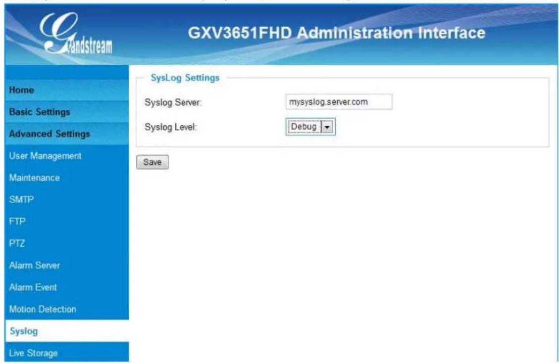
Figure 25 Syslog Configuration Page
- Syslog Server:
Syslog server IP or Domain Name
- Syslog Lever:
Lever of syslog message sent to the syslog server:
None, Debug, Info, Warning, Error.
Live Storage Setting Page (SD Card File Management)
This page allows user to manage the recorded files in SD card:
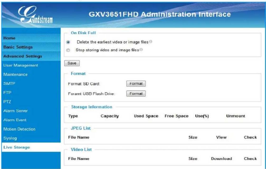
Figure 26 Live Storage Management Page
- On Disk Full:
Select below two different operations when SD card is full
- Delete the earliest video or image files
- Stop storing video and image files
• Storage Information:
The SD card information will be displayed in this column.
- JPEG List:
Motion triggered Snapshot JPEG file will be listed here.
- Video List:
Motion triggered video recording clip will be listed here.
NOTE:
Grandstream free GSNVR DVR software can be downloaded here: http://www.grandstream.com/products/tools/surveillance/GSNVR_1.0.0.28_en.exe
SOFTWARE UPGRADE
Software upgrade can be done either via TFTP, HTTP or HTTPS. The corresponding configuration settings are in the ADVANCED SETTINGS configuration page.
Software Upgrade via TTFP, HTTP or HTTPS
This page allows user to configure firmware upgrade:
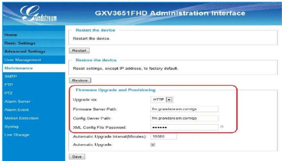
Figure 27 Firmware Upgrade and Provisioning
NOTES:
- Grandstream recommends end-user use the Grandstream HTTP server. Its address can be found at http://www.grandstream.com/support/firmware . Currently the HTTP firmware server FQDN is firmware.grandstream.com. For large companies, we recommend to maintain their own TFTP/HTTP/HTTPS server for upgrade and provisioning procedures.
Instructions for local firmware upgrade using TFTP server:
-
Unzip the file and put all of them under the root directory of the TFTP server.
-
Put the PC running the TFTP server and the device in the same LAN segment.
-
Please go to File -> Configure -> Security to change the TFTP server's default setting from "Receive Only" to "Transmit Only" for the firmware upgrade.
-
Start the TFTP server, in the phone's web configuration page
-
Configure the Firmware Server Path with the IP address of the PC
-
Update the change and reboot the unit
End users can also choose to download the free HTTP server from http://httpd.apache.org/ or use Microsoft IIS web server.
Configuration File Download
Grandstream SIP Device can be configured via Web Interface as well as via Configuration File through TFTP or HTTP/HTTPS. "Config Server Path" is the TFTP or HTTP/HTTPS server path for configuration file. It needs to be set to a valid URL, either in FQDN or IP address format. The "Config Server Path" can be same or different from the "Firmware Server Path".
A configuration parameter is associated with each particular field in the web configuration page. A parameter consists of a Capital letter P and 1 to 3 (Could be extended to 4 in the future) digit numeric numbers. i.e., P2 is associated with "Admin Password" in the ADVANCED SETTINGS page. For a detailed parameter list, please refer to the corresponding firmware release configuration template.
When Grandstream Device boots up or reboots, it will issue request for configuration file named "cfgxxxxxxxxxxxx.xml", where "xxxxxxxxxxx" is the MAC address of the device, i.e., "cfg000b820102ab.xml". The configuration file name should be in lower cases.
Currently GXV3651_FHD only support XML configuration.
RESTORE FACTORY DEFAULT SETTING
WARNING!
Restoring the Factory Default Setting will DELETE all configuration information of the camera. Please BACKUP or PRINT out all the settings before approach to following steps. Grandstream will not take any responsibility if you lose all the parameters of setting or cannot connect to your VoIP service provider.
FACTORY RESET
There are two ways to reset your unit to factory default mode:
Reset Button (Hard Reset)
Reset default factory settings following these four (4) steps:
- Unplug the Ethernet cable.
- Locate a needle-sized hole on the back panel of the camera above the power jack.
- Insert a pin in this hole, and press and hold for about 15 seconds till reboot
- Take out the pin. All unit settings are restored to factory settings.
Reset from Web Interface (Soft Reset)
This page allows user to configure dynamic network related parameters:
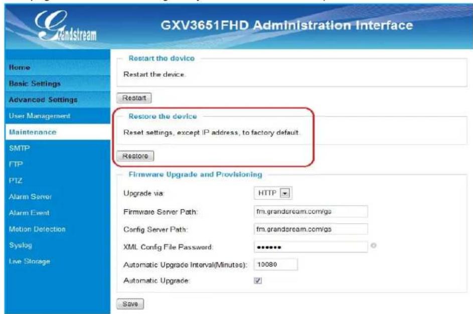
Figure 28 Factory Reset from Web Interface
IP VIDEO SURVEILLANCE FAQ
- What is the default IP address of the GXV-3651_FHD?
The default IP configuration is DHCP.
- Why can I not view the live video stream in Microsoft Internet Explorer?
Please check whether the IE add-on is installed correctly.
Once you log into the GXV 3651_FHD web interface, Internet Explorer will indicate that -This website wants to install to following add-on: _GSViewer.cab' from Grandstream Networks, Inc. Please install this add-on when prompted by IE.
- How do you manually uninstall the Grandstream video viewer add-on for IE?
Please follow these steps to uninstall the add-on:
- Delete the GSViewerX Control from C:\WINDOWS\Downloaded Program Files directory
-
Delete GSNetClient.dll, GS_Replay.exe, GSViewerX.ocx, hi_h264dec_w.dll, lik_VoiceEngine_dll.dll and GSViewerX.inf from C:\WINDOWS\system32
-
Why can't I access the GXV-3651_FHD web configuration interface?
Q 1: Is your internet service down?
A 1: Connect a PC to the internet to test the connection.
Q 2: Are the PC and the device in different subnets?
A 2: Check the subnet mask and default gateway of the device and PC.
Q 3: Is there a conflict with another IP address?
A 3: Try to change the IP address of the device.
Q 4: Has the HTTP port been changed?
A 4: Contact the administrator of the device for more information.
- The GXV-3651_FHD web configuration page is not displayed correctly in Internet Explorer 8?
In IE8, Compatibility View might need to be enabled for the GXV-3651_FHD web configuration page to load properly. To enable compatibility view, open IE8, click Tools, Compatibility View Setting, and add the GXV-3651_FHD web configuration pages to the Compatibility View.
- Why does IE indicate to install Grandstream Video Viewer add-on after a firmware upgrade? The add-on was properly installed before the firmware upgrade process.
New firmware will often upgrade the add-on as well. To watch the live video stream, you must install the newest version of the add-on.
- How do you watch secondary video stream?
Login to the home page of the GXV-3651_FHD web GUI, click Play to watch the video stream. To watch a secondary video stream, right click on the video, and select Secondary Stream on the pop-up menu. Try reinstalling the Grandstream Viewer add-on for IE if you cannot see the video stream.
- Why is audio missing from the recorded video when an alarm is triggered?
Please double check whether the device has an audio input connected. GXV3651_FHD has a MIC IN port for an audio input.
- What is DDNS? Is it important for IP surveillance product to have DDNS support?
DDNS is an acronym for Dynamic Domain Name Service. It is important to choose an IP network camera that has DDNS support for dynamic IP addresses.
Chances are that the network has a dynamic IP address (which changes with every log on). A DDNS service makes sure that the camera's IP address always matches up to the current server address. DDNS also allows for a website to be linked to the IP camera that is constantly updated with the correct information and has a reliable feed.
- Why is Windows Media Player unable to play the recorded videos files?
The GXV-3651_FHD uses the H.264 video codec. Windows Media Player may lack the proper H.264 decoder to play the recorded video. Please download the Microsoft FFDShow H.264 decoder from http://sourceforge.net/projects/ffdshow-tryout/ and install it.
- Alarm Triggered Events do not work in GSurf.
Please double check the Alarm Action on your GXV-3651_FHD. Login to the web GUI of the GXV3651_FHD, go to the Motion Detection or Alarm Events page, and make sure option Upload to Alarm Center is checked.
- It is recommended that you save your video files in different directories when using GSurf and GS_NVR.
GSurf and GS_NVR are different programs that have the ability to delete recorded video files. It is better to save video files in different directories when using GSurf and GS_NVR in the event that they automatically delete files that you might want to keep.
- How can I use a cell phone to watch the GXV3651 FHD video stream?
You must set the video resolution to QCIF to watch the GXV3651_FHD video stream from a cell phone. Make sure to set the bit rate to 64kbps to ensure the best video quality.
- Why doesn't the IP address of the device reset when I click the "Restore" button on the Maintenance page?
The GXV3651_FHD could be installed in areas that are not easy to access. For example, it could be installed on the roof of a building or the ceiling of an office. This makes it difficult to reinstall the device, therefore the -Restorell function will not clear the IP address. Press the RESET button on the device for at least 6 seconds until you hear a beep to perform a factory reset of all parameters (including the IP address).
- Why can't the live video stream be viewed using a mobile phone or GSurf after changing the HTTP Port of the device?
Make sure that the RTSP port of the device is set to 2000 plus the HTTP Port number. For example, if the HTTP port is 88, then the RTSP port of the device that you configured on GSurf / mobile phone should be 2088.
-
Some notes on using SD cards
-
The GXV3651 FHD only supports FAT32 formatted SD cards
- The GXV3651 FHD supports SD and SDHC
- It takes 10-15 seconds to read SDHC cards with large memory capacities. Please wait 15 seconds to unplug the SD card after you plug them into the device.
-
If there are many files (i.e. 1800 or more image batch files) on the SD card, it can take up to 5 minutes to read them. Please do not refresh the web interface at this time as the GXV3651_FHD will restart reading the SD card. Grandstream is currently working on a fix for this issue.
-
Port forwarding
Two ports must be forwarded on your router to watch video from a GXV3651_FHD that is located on a private network from a PC in a public network. The web port (HTTP) and the RTSP port. Please make note that the RTSP port number changes according to the web port. If the web port is 80, then the RTSP port is 554. If the web port is not 80, then the RTSP port equals the web port +2000. For example, if the web port is 88, then the RTSP port will be 2088.
- Tested PC display adapters.
| Display Adapter Test Result | |
| SiS 650/651/740/661 FX/741/760 Series Works normally | |
| Intel(R) 82945R Express Chipset Family Works normally | |
| VIA/S3G UniChrome Pro IGP Works normally | |
| NIVDIA Geforce 7300GS | Works normally |
| SiS 661FX | Works normally |
| SiS Mirage Graphics | Works normally |
| SiS 661 Series Works normally | |
| Intel(R) G33/G31 Express | Works normally |
| SiS Mirage3 Graphics | Works normally |
| SiS 661FX/GX Mirage Graphics | Works normally |
| S3 Graphics ProSavageDDR(Microsoft Corporation) | Works normally |
| XGI Velari Z7/Z9/Z9S V1.08.12 | There is some delay when playing videos. |
| Intel 965 Express Chipset Family | Works normally |
| ATI Mobility Radeon X1300 | Works normally |
| Intel( R ) G45/G43 Express Chipset | Works normally |
| Mobile Intel 965 Express Chipset Family | Works normally |
| Mobile Intel(R) 4 Series Express Chipset Family | Works normally |
| Mobile Intel® 945GM Express Chipset Family | Works normally |
| Mobile Intel® 915GM/GMS, 910GML Express Chipset Family | Works normally |
| Intel® G45/G43 Express Chipset | Works normally |
| ATI Technologies, RAGE XL PCI | This display adapter cannot display videos. |
- Grandstream Networks, Inc.
- TABLE OF CONTENTS
- GXV3651\_FHD User Manual
- WELCOME 4
- PACKAGE CONTENTS 8
- PRODUCT OVERVIEW 9
- INSTALLATION GUIDE ....14
- BASIC SETTINGS EXPLANATION ....20
- ADVANCED SETTINGS EXPLANATION ....30
- SOFTWARE UPGRADE......45
- WELCOME
- Safety Compliances
- Warnings:
- Notice:
- Note:
- Warranty
- Caution:
- PACKAGE CONTENTS
- Equipment Package Contents
- PRODUCT OVERVIEW
- GXV3651\_FHD Key Features
- INSTALLATION GUIDE
- Minimum Recommended System Requirement
- Connect your GXV3651\_FHD
- Using the Power adapter as power supply
- Using PoE as power supply:
- Configuring the GXV3651\_FHD via Web Browser
- Access the GXV3651\_FHD Web Configuration Menu
- Connect to the Camera using Static IP
- GXV3651\_FHD Home Web Page
- GXV3651\_FHD Configuration & Language Page
- BASIC SETTINGS EXPLANATION
- System Settings Page
- Video & Audio Setting Page
- Video Settings
- Primary Stream Settings
- Secondary Stream Settings
- Figure 7 Video & Audio Settings Page
- • Primary Stream Settings:
- • Secondary Stream Settings:
- CMOS Settings Page
- Wi-Fi Settings Page
- Networking Setting Page
- IP Address Configuration
- DNS Configuration
- HTTP
- PPPoE
- DDNS Settings Page
- SIP Setting Page
- Status Page
- ADVANCED SETTINGS EXPLANATION
- User Management Page
- Maintenance Page
- Firmware Upgrade and Provisioning:
- SMTP Setting Page (Email Alarm)
- FTP Settings Page (Upload Alarm)
- PTZ Settings Page
- - PTZ Protocol:
- - PTZ Baud Rate:
- Connect a PTZ device to the GXV3651\_FHD
- Alarm Server Settings Page (Upload Alarm to Supported VMS or HTTP Server)
- Alarm Event Page
- How Alarm Input and Alarm Output Work
- Connect Alarm Input Equipment to the GXV3651\_FHD
- Setup Alarm Actions
- Setup Alarm Event Time Schedule
- How to connect an Alarm Output Equipment to GXV3651\_FHD
- Motion Detection Configuration Page (Set Alarm)
- Alarm Action:
- Syslog Settings Page (Troubleshooting)
- Live Storage Setting Page (SD Card File Management)
- SOFTWARE UPGRADE
- NOTES:
- Instructions for local firmware upgrade using TFTP server:
- Configuration File Download
- RESTORE FACTORY DEFAULT SETTING
- WARNING!
- FACTORY RESET
- Reset Button (Hard Reset)
- Reset from Web Interface (Soft Reset)
- IP VIDEO SURVEILLANCE FAQ
Brand : GRANDSTREAM
Model : GXV-3651FHD
Category : Security Camera