Purepower RX 500W - Computer Adapter THERMALTAKE - Free user manual and instructions
Find the device manual for free Purepower RX 500W THERMALTAKE in PDF.


User questions about Purepower RX 500W THERMALTAKE
0 question about this device. Answer the ones you know or ask your own.
Ask a new question about this device
Download the instructions for your Computer Adapter in PDF format for free! Find your manual Purepower RX 500W - THERMALTAKE and take your electronic device back in hand. On this page are published all the documents necessary for the use of your device. Purepower RX 500W by THERMALTAKE.
USER MANUAL Purepower RX 500W THERMALTAKE
natural_image
Exterior view of a power supply unit (no visible text or symbols on the main body)
Thermaltake
COOL!! YOUR LIFE
www.thermaltake.com thermaltake@thermaltake.com
©2006 Thermaltake Technology Co., Ltd. All Rights Reserved.


natural_image
Four-panel image showing electronic components: a circuit board, a power supply unit, a black cable with connectors, and a power fan (no visible text or symbols)Purepower™ RX
Cable Management 500W ATX12V 2.2 Version
Purepower™ RX
Cable Management 500W ATX12V 2.2 Version
Table of contents
- Introduction 01
- Components Check 02
- Installation 03
3.1 Warnings and Cautions 03
3.2 Embedded Socket and Modularized ..... 04 Cable Management
3.3 Installation Steps 05
3.4 Power Supply Installation 06
- Product Specification 10
4.1 Output Specification
4.2 Purepower RX 500W Power Supply ..... 13
4.3 Other Specification 15
4.4 Protection 15
4.5 Environment 16
4.6 Hi-Pot (Input / Output isolation) 16
4.7 CE Requirements 16
- 12V Rail Distribution ...... 17
- Trouble Shooting 18
- Cable Retail Package 19
Purepower™ RX
Cable Management 500W ATX12V 2.2 Version
1. Introduction
We live up to the promise of Thermaltake logo in our unending quest for excellence.
Shall you have any suggestion or comments,
please access our web site :
http://www.thermaltake.com
or e-mail to :
thermaltake@thermaltake.com
we appreciate your kindly feedback and you will receive the prompt response from our customer service team.
Thank you for choosing a quality Thermaltake Purepower™
RX Cable Management 500W PC Power Supply. We trust that you will find it providing you with many years of service.
You can always find a Thermaltake Purepower™ RX Cable Management 500W PC Power Supply that is suitable for all of your modern PC power needs.
Please take the time in familiarize yourself with the power supply, its connectors and the contents of this manual before proceeding with the installation of the power unit. You will need a Phillips crosshead screwdriver, perhaps your PC case manual and most certainly your motherboard manual.
Purepower™ RX
Cable Management 500W ATX12V 2.2 Version
2. Components Check

500W power supply unit (With one 24-pin main connector & 6-pin PCI-Express connector)
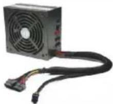
natural_image
Exterior view of a computer power supply unit with fan and cord (no visible text or symbols)2 A 4-pin/8-pin +12V power connector
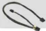
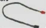
4 Two sets of wires with 4-pin floppy drive connector
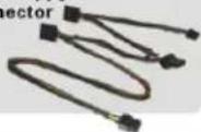
6 Two sets of wires with 5-pin SATA connectors
8 4 mounting screws
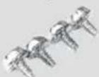
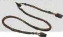
3 Two sets of wires with 4-pin peripheral power connector
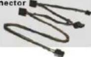
5 Two sets of wires with 6-pin PCI-Express connectors
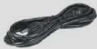
7 One AC Input power cord
9 User manual
Purepower™ RX
Cable Management 500W ATX12V 2.2 Version
3. Installation
3.1 Warnings and Cautions
3.1.1 Do not pull the AC power cord when the power supply is in use or else damage to components will result.
3.1.2 Do not store the Power Supply in a high humidity and high temperature environment.
3.1.3 When using Purepower RX Cable Management 500W power supply under testing conditions where the power supply unit is not installed in a PC with its components, please follow the steps below:
1) Please take a paper clip and untwist it.
2) Make sure the power supply unit is in the "OFF" position.
3) Locate the 20 or 24 pin motherboard connector from the power supply unit.
4) Plug one side of the paper clip into the green wire hole.
5) Plug the other side of the paper clip into any of the black wire holes.
6) Turn on the PSU to see if the power supply fans turn on.
3.1.4 High voltages exist in the power supply. Do not open the power supply case unless you are an authorized service technician or electrician.
3.1.5 All warranties and guarantees shall be voided should there be a failure to comply with any of the warnings and cautions covered in this manual.
Purepower™ RX
Cable Management 500W ATX12V 2.2 Version
3.2 Embedded Socket and Modularized Cable Management
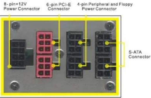
3.2.1 Embedded Socket and Modularized Cable Management: The new embedded socket and modularized cable management allows user use only the cables they need and improve the airflow in the chassis.
Embedded Socket and Modularized Cable Management Design:
text_image
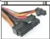
8-pin+12V Power Connector 6-pin PCI-E Connector 4-pin Peripheral and Floppy Power Connector S-ATA Connector3.2.2 Purepower RX Cable Management 500W unit: On the power supply, you will find sockets to connect with those cables. Users can choose which wire set they want to use for devices, graphic card, fans, etc. Inside the package, you will find the following wire set:
- One 8-pin/4-pin +12V connector
- Seven 4-pin peripheral power connectors and two 4-pin floppy drive connectors
- Four 5-pin S-ATA connectors
- Two 6-pin PCI-Express graphic card connectors
Purepower™ RX
Cable Management 500W ATX12V 2.2 Version
3.3 Installation Steps
To prevent electrical shocks, please disconnect the power cord from your existing power supply unit. Purepower RX Cable Management 500W PSU has automatic Voltage Selector Which will automatically change to 100V-240V PSU.
Installation Steps
3.3.1 Ground yourself to remove any static electricity by briefly touching your PC cases and then, disconnect the power cord from your old power supply (if replacing it)
3.3.2 Follow your computer case manual and disassemble the case.
3.3.3 Disconnect all the power connectors from the motherboard and from the peripheral devices such as case fans, hard drives, floppy drives. etc.
3.3.4 Remove the existing power supply from your computer case and replace it with your new Thermaltake Purepower™ RX Cable Management 500W PSU.
3.3.5 Connect the power connectors to the motherboard and peripheral devices (refer to the rest of this manual to match the various one-way key-locked connectors to the motherboard and accessories).
3.3.6 Connect the 6-pin PCI Express connector to PCI Express graphic card if you need.
Note: Please read the user manual supplied with your graphic card for detail usage instructions.
3.3.7 Close the computer case.
3.3.8 Make sure your power supply switch is on "OFF" position, and connect the supplied power cord to your Thermaltake Purepower™ RX Cable Management 500W PSU.
Purepower™ RX
Cable Management 500W ATX12V 2.2 Version
3.4 Power Supply Installation
Step 1 Step
After install the power supply unit into the chassis and then connect the 20+4-pin main power cable to motherboard 20pin or 24 pin socket.
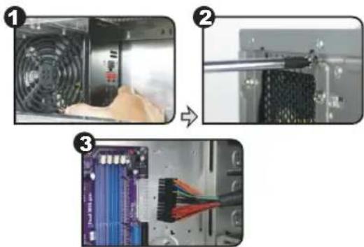
text_image
Three-step diagram showing computer hardware installation: fan, rack-mounted drive, and motherboard with CPU socket wiring.Step 2 Step
Connect the 4-pin/8-pin +12V auxiliary power connector to the motherboard. (Users can use either 4 pins or 8 pins, depending on the motherboard. Please check with the motherboard user's manual.)
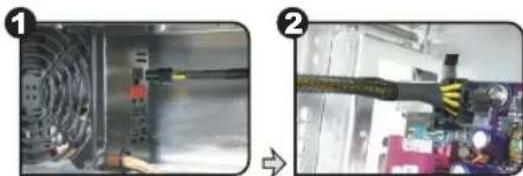
natural_image
Two-panel image showing a device interior and a close-up of a cable or connector assembly (no visible text or symbols)Purepower™ RX
Cable Management 500W ATX12V 2.2 Version
Step 3 Step
Note: Please check the below information before install your Dual PCI-Express graphic cards.
The Purepower RX 500W Cable Management Power Supply has three PCI-Express connectors.
One of the PCI-Express connectors comes out directly from the power supply unit, the other two PCI-Express connectors are modularized design.
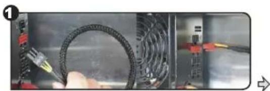
For the below SLI and CrossFire dual graphic card mode, you have to use one PCI-Express connector which comes out from the power supply unit and one modularized PCI-Express connector for best performance and stability.
| NVIDIA SLI Card ATI CrossFire Card | |
| GeForce 7900 GTX | Radeon X1900 series |
| GeForce 7900 GT | Radeon X1800 series |
| GeForce 7800 GTX 512MB | Radeon X1600 series |
| GeForce 7800 GTX 256MB | Radeon X1300 series |
| GeForce 6800 Ultra | |
| GeForce 6800 GT | |
| GeForce 6800 | |
*Please check Thermaltake website for installation instruction on future graphic cards.
For other entry level SLI or CrossFire graphic cards, you can use two 6-pin modularized PCI-Express connectors.
First, high-level SLI or CrossFire dual graphic card mode installation: Connect one PCI-Express connector which comes out from power supply unit and one 6-pin modularized PCI-Express connector to your dual graphic cards.
Purepower™ RX
Cable Management 500W ATX12V 2.2 Version
natural_image
Close-up of a hand holding a black cable with a probe inserted, next to an open electrical panel (no visible text or symbols)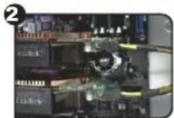
natural_image
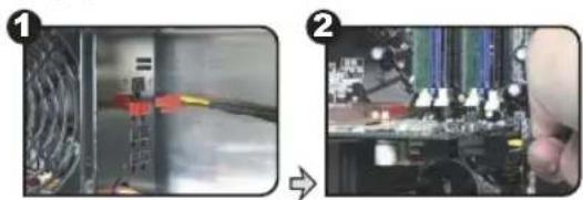
Close-up of a computer motherboard with visible circuitry and components (no readable text or symbols)Second, entry-level SLI or CrossFire dual graphic card mode such as NVIDIA 6600 series and ATI X850 series installation:
Connect the two 6-pin modularized PCI-Express connector to your dual graphic cards.
natural_image
Two-panel image showing a computer interface with connected cables and a close-up of a hand holding a circuit board (no visible text or symbols)Step 4 Step
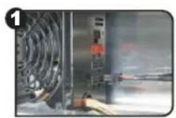
Connect the 4-pin power connectors to peripherals such as DVD burners, hard disk drives, etc. In addition, users can connect the 4-pin floppy power connectors to the floppy drive.
Purepower™ RX
Cable Management 500W
ATX12V 2.2 Version
natural_image
Close-up of a mechanical device with a hand operating a tool, no visible text or symbols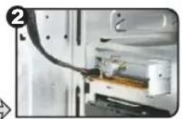
natural_image
Close-up of a mechanical device with a cable inserted into a housing (no visible text or symbols)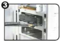
natural_image
Interior view of a computer with an open drive and a black plastic cover (no visible text or symbols)Purepower™ RX
Cable Management 500W
ATX12V 2.2 Version
4. Product Specification
4.1 Output Specification
Main Power Connector
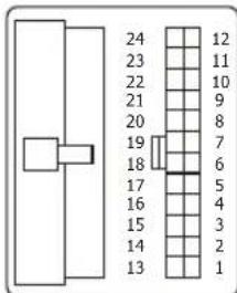
text_image
24 23 22 21 20 19 18 17 16 15 14 13 12 11 10 9 8 7 6 5 4 3 2 1| Voltage | Color | Color | Voltage | ||
| +3.3 V | Orange | 1 | 13 | Orange | +3.3 V |
| +3.3 V | Orange | 7 | 14 | Blue | -12 V |
| COM | Black | 3 | 15 | Black | COM |
| +5 V | Red | 4 | 16 | Green | PS_ON |
| COM | Black | 5 | 17 | Black | COM |
| +5 V | Red | 6 | 18 | Black | COM |
| COM | Black | 7 | 19 | Black | COM |
| PWR_ON | Gray | 8 | 20 | N/C | N/C |
| +5 Vsb | Purple | 9 | 21 | Red | +5 V |
| +12 V | Yellow/Blue | 10 | 22 | Red | +5 V |
| +12 V | Yellow/Blue | 11 | 23 | Red | +5 V |
| +3.3 V | Orange | 12 | 24 | Black | COM |
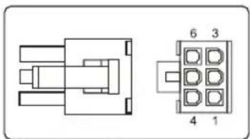
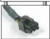
PCI Express Connector (6 pin)
natural_image
Pure electrical connector diagram without any text, numbers, or symbols| Color | Signal | Pin |
| Yellow | +12VDC | 1 |
| Yellow | +12VDC | 2 |
| Yellow | +12VDC | 3 |
| Black | COM | 4 |
| Black | COM | 5 |
| Black | COM | 6 |
Purepower™ RX
Cable Management 500W ATX12V 2.2 Version
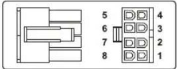
+12V Connector (8 pin)
text_image
5 6 7 8 4 3 2 1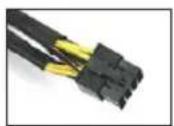
| Color | Signal | Pin |
| Black | COM | 1 |
| Black | COM | 2 |
| Black | COM | 3 |
| Black | COM | 4 |
| Yellow/Black | +12DCV | 5 |
| Yellow/Black | +12DCV | 6 |
| Yellow | +12DCV | 7 |
| Yellow | +12DCV | 8 |
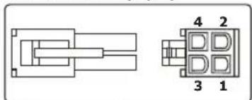
+12V connector (4 pin)
natural_image
Pure electrical connector diagram without any text or symbols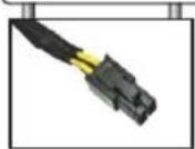
| Color | Signal | Pin |
| Black | COM | 1 |
| Black | COM | 2 |
| Yellow/Black | +12V _1 | 3 |
| Yellow/Black2V | 4 _1 |
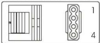
Peripheral Connector (4 pin)
natural_image
Pure electrical connector pinout diagram without any text or symbols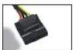
| Color | Signal | Pin |
| Yellow/Orange | +12 V_3 | 1 |
| Black | COM | 2 |
| Black | COM | 3 |
| Red | +5VDC | 4 |
Purepower™ RX
Cable Management 500W ATX12V 2.2 Version
Floppy Disk Connector (4 pin)
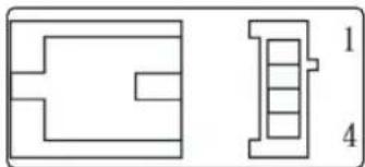
natural_image
Pure technical line drawing of two mechanical or architectural components without any text, numbers, or symbols
| Color | Signal | Pin |
| Red | +5VDC | 1 |
| Black | COM | 2 |
| Black | COM | 3 |
| Yellow/Orange | +12 V_3 | 4 |
Serial ATA Power Connector
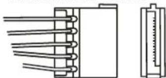
natural_image
Pure electrical connector diagram without any text, numbers, or symbols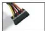
| Color | Signal | Pin |
| Yellow/Orange | +12 V_3 | 1 |
| Black | COM | 2 |
| Red | +5VDC | 3 |
| Black | COM | 4 |
| Orange | +3.3 VDC | 5 |
Purepower™ RX
Cable Management 500W ATX12V 2.2 Version
4.2 Purepower RX Cable Management 500W PSU Specification
F eatures:
- Complies with ATX 12V 2.2 version.
- Compatible with latest PCI-Express and Dual Core CPU configuration.
- Three dedicated +12V output circuitry provides stable voltage for system.
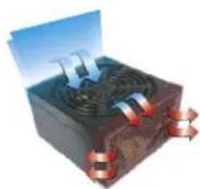
- Modularized cable management improves internal airflow.
- Universal AC input
115\~230V automatically scans and detects the correct voltage for different country.
- Quiet and reliable 140mm ball bearing fan.
- Industrial grade protections: Over current, Short-Circuit, and Over voltage.
- Safety / EMI Approvals: CE FCC, UL, CUL, TUV, and BSMI certification.
natural_image
3D illustration of a power plant with cooling fans and heat exchangers (no text or symbols)SPECIFICATION
| P/N | W0142 |
| Maximum Power | 500 Watts |
| Color | HI-Tech Black |
| Switches | ATX Logic on-off additional power rocker switch |
| PFC (Power Factor Correction) | Active PFC |
| Cooling System | 14cm Fan SPEED: 1900 RPM(+10%~10%) DIMENSION: 140 X 140 X 25 mm AIR FLOW: 86.5 CFM BEARING TYPE : Two Ball Bearing TEMP. AUTO CONTROL |
| Noise | 16 dBA at 1300 RPM |
| P. G. Delay | 100-500 ms |
| Over Voltage Protection Recycle AC to Reset | +5V trip point < +7.0V +3.3V trip point < +4.5V +12V trip point < +15.6V |
DIMENSIONS
| Unit Size | 16cm(L)x15cm(W)x8.6cm(H) |
| Net Weight | 2.24 kg |
| INPUT | |
| Input Voltage | 115VAC - 230VAC |
| Input Frequency Range | 47 - 63 Hz |
| Input Current | 6A/3A |
| Hold-up Time | 16 ms |
| Efficiency | Typical 75% |
Purepower™ RX
Cable Management 500W ATX12V 2.2 Version
▶ Total Output Connector
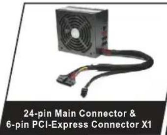
text_image
24-pin Main Connector & 6-pin PCI-Express Connector X1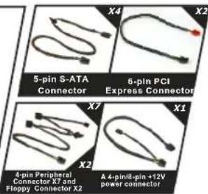
text_image
5-pin S-ATA Connector 6-pin PCI Express Connector 4-pin Peripheral Connector X7 and Floppy Connector X2 A 4-pin/8-pin +12V power connector▶ Technology Features
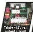


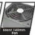
▶ Cable Application
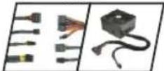
Intelligent Cable Management:
- All cables are sleeved with black mesh cablesleeving
● Optimum air-flow currents within the chassis
| OUTPUT | |||||||
| Voltage | +5V | +3.3V | +12 V_3 | <12 V_3 | +12 V_3 | -12V | +5VSB |
| Max. Load | 16A | 22A | 18A | 18A | 16A | 0.8A | 3.0A |
| Min. Load | 2.0A | 0.5A | 1.0A | 1.0A | 1.0A | 0.0A | 0.0A |
| Reak Load | - | - | - | - | - | - | 3.5A |
| Load Reg. | +5%-4% | +5%-3% | +5%-4% | +5%-4% | +5%-4% | +9%-5% | +5%-3% |
| Rippl & Noisee | 50mV | 50mV | 120mV | 120mV | 120mV | 120mV | 50mV |
Purepower™ RX
Cable Management 500W ATX12V 2.2 Version
4.3 Other Specification
4.3.1 Inrush Current:
55A max. when AC input 115Vac at 25°C cold start.
110A max. when AC input 230Vac at 25°C cold start.
4.3.2 Power Efficiency:
75% (min.) at full load typical and 115Vac input.
4.3.3 Power Factor:
PF>0.9
4.3.4 Note:
The continuous total output power is 500W max.
The combined power of +5V and +3.3V is 130W max.
Total combined +12V output load not exceed 36A.
Peak currents may last up to 12 seconds with not more than one
occurrence per minute.
4.3.5 Hold-Up Time:
16msec (minimum) at 80% of full load at 230Vac input.
4.3.6 Power Good Delay:
100-500 msec.
4.3.7 Power Fail Delay:
1 msec.
4.3.8 Turn-On Delay
Time:
2000 msec max.
4.3.9 Rise
Time:
20ms max at full load.
4.4 Protection
When OCP, OVP or short protection is triggered, the main outputs will be latched off. The main outputs can be reset by cycling the DC remote on/off or AC power. +5Vsb output is auto recovery when fault condition removed.
4.4.1 Over Current Protection
N otov er240VA f oreve ryoutp utvoltage.
1 9 A to 28A for every +12 rail.
4.4.2 Over Voltage Protection
+3.3V output 4.5 Vmax
+5.0V output 7.0 Vmax
+12.0V output 15.6 Vmax
Purepower™ RX
Cable Management 500W ATX12V 2.2 Version
4.4.3 Short Protection
All outp ut toGND.
4.5 Environment:
4.5.1 Operating Temp. 10°C to +50°C
4.5.2 Storage Temp. -20°C to +70°C
4.5.3 Operating Humidity 20% to 90%, non-condensing
4.5.4 Storage Humidity 5% to 95%, non-condensing
4.5.5 Operating Altitude 0 to 10,000 feet
4.5.6 Storage Altitude 0 to 50,000 feet
4.6 Hi-Pot: (Input/Output isolation)
4.6.1 Primary to Secondary
4242vdc for 1 minute
4.6.2 Insulation Resistance Primary toear thground 500Vdc, 50M ohms Min.
4.7 CE Requirements
4.7.1 Conducted EMI
4.7.2 Safety Standards
1.Me etCUL (UL 60950)
2.Me etTU V EN60950
3.Me etC B (IE C 950)
- Meet C E
4.7.3 Harmonic
4.7.4 MTBF at 25°C(demonstrated)
100k hrs minimum
Purepower™ RX
Cable Management 500W ATX12V 2.2 Version
5. 12V Rail Distribution
| 12V Rail Distribution(Purepower RX 400W / 450W / 500W / 550W / 600W) | |||
| Model | W0141 450WW0148 400WW0149 450W | W0142 500WW0143 550WW0150 550W | W0144 600W |
| 24 PIN Connector | 12V1 | 12V3 | 12V3 |
| 4 PIN +12V Connector | 12V2 | 12V1 | 12V1 |
| 8 PIN+12V Connector | -- | 12V1,12V2 | 12V1,12V2 |
| Peripheral & Floppy Connector | 12V1 | 12V3 | 12V4 |
| S-ATA Connector | 12V1 | 12V3 | 12V4 |
| Modular PCI-E Connector | 12V1 | 12V2 | 12V2 |
| Modular PCI-E Connector | -- | 12V2 | 12V2 |
| Native PCI-E Connector | -- | 12V3 | 12V3 |
For the 500W\~600W model, please follow below connector's operation instruction.
-
When you are using 8pin CPU +12V connector and only one graphic card with one PCI-E connector, please use native PCI-E connector to your card.
-
When you are using 4 pin CPU +12V connector and only one graphic card with one PCI-E connector, please use modular PCI-E connector to your card.
-
When you are using 8pin CPU +12V connector and two graphic cards, please use one modular PCI-E connector and one native PCI-E connector to your cards.
-
When you are using 4pin CPU +12V connector and two graphic cards, please use one modular PCI-E connector and one native PCI-E connector to your cards.
Note: For the latest NVIDIA or ATI Graphic Card, please check our website to ensure the compatibility.
Purepower™ RX
Cable Management 500W ATX12V 2.2 Version
6. Trouble Shooting
Condition 1:
No DC output. The fan or fans are motionlessCheck:
1-1 Is the AC inlet plug firmly plugged into the PSU inlet socket?
1-2 Is the wall socket, extension power cord, power strip or surge protector in use, fully functional and wall power switch turned 'ON'?
1-3 Is the Main Board socket (24pin) plug fully and firmly inserted?
Condition 2:
The fan or fans began rotating and then stopped. The system hangs without proceeding any further.
Check:
2-1 Are the peripheral connectors firmly plugged into accessory devices, such as the main hard drive, CD ROM, etc?
2-2 If a plug has been inadvertently connected in an off-set or reversed position, unplug the AC power source, reconnect the offending connectors and then wait for 30 seconds before replug in the AC power source and try again.
Note:
If the power supply still cannot or is still unable to power up after following the above instruction, please send the unit back to your dealer or retailer for after sales service.
Purepower™ RX
Cable Management 500W ATX12V 2.2 Version
7. Cable Retail Package(Optional)
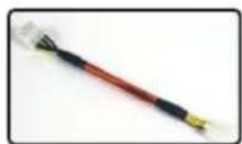
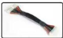
P/N:A2169 PSU Adaptor Cable Specification
| (A) | (B) | |
| Model | Adaptor Cable | Adaptor Cable |
| Dimension (mm) | 193mm | 198mm |
| Connector type | 4pin - 8pin 20pin - 24pin | |
| Cable sleeving color | Red | Black |
| Material | Plastic | Plastic |
| Weight | 16 g | 58 g |
| Voltage | 12 V | 3.3V,5V,+12v,-12V |
(A)4pin-8pin
(B)20pin-24pin
Purepower™ RX
Cable Management 500W ATX12V 2.2 Version
Note