
EKHWMX300CA - Chauffe-eau instantané et chauffe-eau DAIKIN - Free user manual and instructions
Find the device manual for free EKHWMX300CA DAIKIN in PDF.


| Product Type | Electronic Controller for Heat Pump Water Heater (Daikin Altherma M ECH₂O) |
| Model | EKHWMX300CA (Part of RoCon mb control system) |
| Brand | Daikin |
| Category | Instantaneous Water Heater & Water Heater (Heat Pump System) |
| Controller Type | Digital Regulator with Plain Text Display |
| Display | Color Backlit LCD, 7 Languages |
| Power Supply | 230 V AC, 50/60 Hz (System Dependent) |
| Operating Modes | Standby, Heating, Cooling, Summer, Reducing, Automatic 1, Automatic 2 |
| Hot Water Temperature Range | 10°C to 70°C (Anti-legionella up to 70°C) |
| Heating Temperature Range | 10°C to 90°C (Flow Temperature) |
| Cooling Temperature Range | 5°C to 25°C |
| Safety Features | Frost Protection, Anti-legionella, Overheat Protection, Water Shortage Shut-off |
| Timer Programs | 4 Permanent (2 Heating, 2 DHW), 1 Circulation, 4 Temporary (Party, Away, Holiday, Vacation) |
| Weather-Dependent Control | Yes (Heat/Cooling Slope Adjustable) |
| Smart Grid Ready | Yes (EVU Function HT/NT and SG Signals) |
| Connectivity | CAN Bus (Optional: Room Station, Mixer Module, Gateway for Remote Control) |
| Backup Heater Support | Yes (Optional EKBUxx, Emergency Operation Mode) |
| Cleaning Instructions | Use Dry Cotton Cloth; Avoid Moisture and Aggressive Cleaners |
| User Interface | Rotary Switch, Rotary Button, Exit Key |
| Password Protection | Technician Code for Expert Settings |
Frequently Asked Questions - EKHWMX300CA DAIKIN
User questions about EKHWMX300CA DAIKIN
0 question about this device. Answer the ones you know or ask your own.
Ask a new question about this device
Download the instructions for your Chauffe-eau instantané et chauffe-eau in PDF format for free! Find your manual EKHWMX300CA - DAIKIN and take your electronic device back in hand. On this page are published all the documents necessary for the use of your device. EKHWMX300CA by DAIKIN.
USER MANUAL EKHWMX300CA DAIKIN
Operating instructions
Control unit RoCon mb, EHS157034, EHS157068

natural_image
Three technical illustrations of industrial control panels: front panel, side panel with control panel, and side panel with control panel (no text or symbols visible)
natural_image
3D rendering of a cylindrical device with lid and control buttons (no text or symbols visible)Electronic controller for heat pumps
EKHWMX300C
EKHWMXB300C
EKHWMX500C
EKHWMXB500C
Operating instructions
Control unit RoCon
EHS157068
mb, English
1 Safety 4
1.1 Refer to the manual 4
1.2 Warning signs and explanation of symbols ..... 4
1.2.1 Meaning of the warnings .....4
1.2.2 Validity.....5
1.2.3 Handling instructions....5
1.3 Avoiding danger 5
1.4 Use as intended 5
2 Product description.... 6
3 Operation 7
3.1 General 7
3.2.1 Display 7
3.2.2 Controls....8
3.3 Operating concept 9
3.4 Basic functions and operating modes ..... 10
3.4.1 System information (Info) 10
3.4.2 Setting the operating mode .....12
3.4.3 Temperature setting of daytime room temperature.14
3.4.4 Temperature setting of setback mode.....14
3.4.5 Temperature setting of hot water generation .....14
3.4.6 Unscheduled hot water preparation .....14
3.4.7 Switching time program....14
3.4.8 System settings.....17
3.4.9 Terminal function....17
3.4.10 Operation with glycol....18
3.4.11 Whisper mode .....18
3.4.12 Smart Grid (SG) 19
3.4.13 EHS emergency operation .....19
3.5 Special functions ..... 20
3.5.1 Manual operation .....20
3.5.2 3-way switching valves reference travel.....20
3.6 Special system settings 21
3.6.1 Access rights (technician code) .....21
3.6.2 Heat slope .....21
3.6.3 Cooling slope .....22
3.6.4 Weather-dependent T-HS control .....23
3.6.5 Frost protection function .....23
3.6.6 Interlink function .....24
3.6.7 Additional alternative heat generator .....24
3.6.8 Heating support .....25
3.6.9 Special function: switching contacts .....25
3.6.10 Air purge .....25
3.6.11 Anti-legionella system .....26
3.6.12 Resetting to factory settings (reset) .....26
3.6.13 Screed program .....27
3.6.14 Relay test 29
3.6.15 Settings for optional circulation pump .....29
3.6.16 Remote control via Internet . . . . . . . . . . . . . . . . . . . . . . . . . . . . . . . . 30
4 Initial start-up 31
4.1 Fundamental aspects of the IDs and authorisations in the RoCon system ..... 31
4.2 Operating Support during 1st. Commissioning and during System Extensions....32
4.3 Commissioning Daikin Altherma M ECH 2O .... 33
4.3.1 Assigning the terminal ID on the RoCon B1 control panel of the Daikin Altherma M ECH₂O .....33
4.4 Putting optional RoCon system components into operation 33
4.4.1 Mixer module EHS157068.... 33
4.4.2 EHS157034 room station 34
4.4.3 Allocating the EHS157068 mixing module to a heat generator 35
4.4.4 Master RoCon function 35
4.4.5 Caretaker function 35
5 Parameter overview. 36
5.1 For first commissioning or resetting to factory settings 36
5.2 After first commissioning/After successful basic configuration 37
5.2.1 Rotary switch setting: Configuration 37
5.2.2 Rotary switch setting: DHW Install 38
5.2.3 Rotary switch setting: Operating Mode ..... 38
5.2.4 Rotary switch setting: Set Temp Day 38
5.2.5 Rotary switch setting: Set Temp Night 38
5.2.6 Rotary switch setting: DHW Set Temp ..... 38
5.2.7 Rotary switch setting: Time Program ..... 38
5.2.8 Rotary switch setting: Remote Param 38
5.2.9 Rotary switch setting: Info 38
5.2.10 Exit key: Special function.... 38
5.3 Parameter levels for the EHS157068 mixer module 38
5.3.1 Rotary switch setting: Info 38
5.3.2 Rotary switch setting: Operating Mode ..... 38
5.3.3 Rotary switch setting: Set Temp Day ..... 38
5.3.4 Rotary switch setting: Set Temp Night ..... 38
5.3.5 Rotary switch setting: DHW Set Temp ..... 38
5.3.6 Rotary switch setting: DHW Install 38
5.3.7 Rotary switch setting: Time Program ..... 39
5.3.8 Rotary switch setting: Remote Param 39
5.3.9 Rotary switch setting: Configuration 39
6 Parameter settings 40
6.1 Explanation of the parameter tables ..... 40
6.2 Rotary switch setting: Configuration ..... 40
6.2.1 "Setup" level 40
6.2.2 "System Configuration" level 44
6.2.3 "HC Configuration" level 45
6.2.4 "DHW Configuration" level..... 47
6.3 Rotary switch setting: DHW Install 47
6.4 Rotary switch setting: Operating Mode ..... 48
6.5 Rotary switch setting: Set Temp Day ..... 48
6.6 Rotary switch setting: Set Temp Night ..... 48
6.7 Rotary switch setting: DHW Set Temp ..... 48
6.8 Rotary switch setting: Time Program ..... 49
6.9 Rotary switch setting: Remote Param ..... 49
6.10 Rotary switch setting: Info 49
6.11 Exit key: Special function 50
6.12 "Basic Configuration" parameter level.....51
6.13 Parameter levels of the EHS157068 mixer module 51
6.13.1 Rotary switch setting: Configuration, "Setup" level 52
6.13.2 Rotary switch setting: Configuration, "Mixer Config" level 53
7 Errors, malfunctions and messages ..... 55
7.1 Recognising errors, correcting malfunctions . . . 55
7.1.1 Current error display 55
7.1.2 Reading out the protocol 55
7.1.3 Troubleshooting.... 55
7.2 Emergency operation 56
7.3 EHS emergency operation .....56
7.4 Malfunctions and fault codes .....56
8 Glossary....57
9 Notes ....58
9.1 User-specific settings .....58
9.1.1 Switching time program 58
9.1.2 Parameters 59
9.1.3 IDs in the RoCon CAN bus system ..... 59
9.2 Other items .....60
10 List of keywords .....63
1 Safety
1.1 Refer to the manual
These instructions are the >> translation of the original version << in your language.
All the activities required for operation and setting the parameters are described in this instruction manual. All parameters needed for trouble-free operation have been configured at the factory.
- Please read through this manual carefully before operating the heating system or before adjusting the settings for it.
- Make a note of the preset values before you make any changes to the unit configuration.
Relevant documents
– Daikin Altherma M ECH _2 O:
- Installation and maintenance instructions
– Operating instructions for the user/owner
- Commissioning checklist
– the operating manual for the user/owner
- Outdoor unit for Daikin Altherma M ECH _2 O: the respective installation and operating instructions.
- On connection of a Daikin solar system: the respective installation and operating instructions.
- On connection of a Daikin FWXV-ATV3: the respective installation and operating instructions.
- For connecting to another Daikin heat generator or optional accessories: the associated installation and operating instructions.
The guides are included in the scope of supply for the individual units.
1.2 Warning signs and explanation of symbols
1.2.1 Meaning of the warnings
Warnings in this manual are classified according into their severity and probability of occurrence.

DANGER!
Draws attention to imminent danger.
Disregarding this warning can lead to serious injury or death.

WARNING!
Indicates a potentially dangerous situation.
Disregarding this warning may result in serious physical injury or death.

CAUTION!
Indicates a situation which may cause possible damage.
Disregarding this warning may cause damage to property and the environment.

This symbol identifies user tips and particularly useful information, but not warnings or hazards.
Special warning signs
Some types of danger are represented by special symbols:

Electric current

Risk of burning or scalding
1.2.2 Validity
Some information in this manual has limited validity. The validity is highlighted by a symbol.
Only valid for Daikin Altherma M ECH₂O with cooling function
U1 Only valid/available with a connected room station (EHS157034)
M1 Only valid/available with a connected mixer module (EHS157068)
1.2.3 Handling instructions
- Handling instructions are shown as a list. Actions for which the sequential order must be maintained are numbered.
→ Results of actions are identified with an arrow.
Display readouts of the RoCon controller
Entry into a setting procedure
Exit from a setting procedure
Certain screen displays or menu items may deviate from those shown in these instructions depending on the national or equipment variant of the Daikin Altherma M ECHO or the user status logged onto the controller.
1.3 Avoiding danger
The Daikin Altherma M ECH _2 O is built according to the state-of-the-art and the recognised technical rules. However, improper use may result in serious physical injuries or death, as well as property damage.
To avoid hazards, only operate the Daikin Altherma M ECHO:
- as stipulated and in perfect condition, - with an awareness of safety and the hazards involved.
This assumes knowledge and use of the contents of this manual, of the relevant accident prevention regulations as well as the recognised safety-related and occupational health rules.

WARNING!
This equipment must only be used by children aged 8 and above and by persons with restricted physical, sensory or mental capabilities or with a lack of experience and knowledge, if they are under supervision or if they have been instructed in the safe use of the equipment and understand the dangers arising therefrom.
Children must not play with the equipment. Cleaning or user maintenance must not be carried out by children without supervision.
1.4 Use as intended
The RoCon mb controller must only be used in Daikin Altherma M ECH₂O heat pumps that are approved for the Daikin RoCon regulating system. The Daikin RoCon mb must only be operated as per the data in these instructions.
Any other use outside the intended use is considered as improper. The operator alone shall bear responsibility for any resulting damage.
For any work on the equipment, which extends above and beyond the operation of the regulating system, you must observe the details provided in the supplementary documents, particularly with regard to safety instructions.
2 Product description

The RoCon mb controller is part of the Daikin Altherma M ECH₂O.
It consists of the RoCon BM1 printed circuit board, to which the actuators, sensors and further components of the Daikin RoCon regulating system are connected, and the RoCon B1 control panel.
In this instruction manual we explain just the functions and setting possibilities of the control unit. More detailed information on the Daikin Altherma M ECH₂O and other device components can be found in the other applicable documents.
Depending on heater unit, the electronic, digital controller automatically regulates all heating, cooling and hot water functions for a direct heating circuit, a storage tank charging circuit and, via mixer modules that can be optionally connected, also further heating circuits.
It undertakes all safety management for the Daikin Altherma M ECH _2 O. This executes a safety switch-off in the event of a water shortage or undefined operating states. A corresponding error message shows the operator all the information for fault causes.
All function settings for the Daikin Altherma M ECH₂O and the optional RoCon devices that are connected via the data bus are undertaken with the controls of the integrated RoCon B1 control panel and shown on the plain text display with coloured backlighting.
The following additional, optional devices can be connected to the Daikin Altherma M ECHO via the controller data bus:
– EHS157034 room station.
– EHS157068 mixer module.
In addition, the RoCon mb controller has a frost protection function for the direct heating circuit and the storage tank charging circuit as well as an automatic function for heating support (integration of an additional heat source such as a wood-burning boiler or solar system).
The potential-free AUX switching contact can be used to carry out different control functions in conjunction with external devices (demand from an external heat generator, switching to bivalent operating mode, external status display, etc.).
Several inputs for evaluating external control contacts are also available (external operating mode switching or heat request, Smart Grid and off-peak EVU functions ^1 ).
1) Utility company (EVU) outputs signals that are used to control power grid capacity utilisation and influence the electricity price and availability.
With the optional EKRSC1 outside temperature sensor that is installed on the north side of the building, weather-dependent T-HS control can be further optimised.
If the optional EHS157056 gateway is installed and connected to the Internet, the Daikin Altherma M ECHO can be conveniently monitored and operated by remote control using a mobile phone (app).
The RoCon mb control unit contains a timer which can be used to set:
- 2 individual adjustable switching time programs ^2) for room heating and room cooling (direct heating circuit),
- 2 individually-adjustable timer programs for hot water generation,
- 1 individually-adjustable timer program for an optional circulation pump.
2) Use of the switching time programs for room cooling only in combination with a connected room thermostat
Initial commissioning of the heating system is described in the installation instructions for the Daikin Altherma M ECH₂O.
Certain menu items of the RoCon mb control unit are only accessible for the heating expert. This security measure ensures that no undesirable malfunctions arise during operation of the system through incorrect settings.
The EHS157034 room station has the same user interface as the Daikin Altherma M ECH _2 O's integrated RoCon B1 control panel.
All settings for the allocated heating circuit can be carried out in the same way as the operating unit. With activated terminal function, all operating possibilities that are available on the integrated operating unit are available, with the exception of certain special functions (e.g. Manual Operation).
After corresponding assignment, a connected EHS157068 mixer module is also operated using the RoCon B1 control panel and/or the EHS157034 room station.
3 Operation
3.1 General

DANGER!
If electrical components come into contact with water, this can cause an electric shock as well as cause potentially fatal burns or injuries.
- The displays and the keys of the control unit must be protected against the effects of moisture.
- To clean the control unit, use a dry cotton cloth. Using aggressive cleaning agents and other fluids can cause damage to devices or lead to an electric shock.

Maximum energy exploitation
The Daikin Altherma M ECH₂O makes the most effective use of energy at the lowest possible return and target hot water temperature.
If an external heat generator (e.g. the optional backup heater) is activated at target feed temperatures over 50 °C, the efficiency (COP) of the Daikin Altherma M ECHO can deteriorate (depending on the outside temperature).
3.2 Display and operating elements
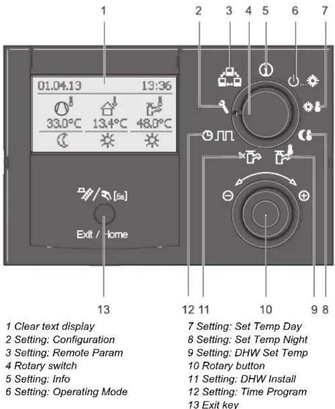
Fig. 3-1 Arrangement of display and operating elements
3.2.1 Display
All operating steps are supported by corresponding displays on a coloured backlit plain text display.
The menu guidance can be displayed 7 languages (see chap. 3.4.8).

Malfunctions are generally indicated by a fault code and a clear text fault message on the display.
For troubleshooting instructions, see Chapter 7.
The colour of the backlighting indicates the operational status and the operating mode:
White: Standard lighting, normal operating display.
Red: Fault status; depending on the type of fault, the Daikin Altherma M ECH₂O continues to operate with restrictions.
Green: Operating mode with operator authorisation.
Blue: Operating mode with expert authorisation.

1 Display date
2 Refrigerant compressor status
3 Status display (e.g. technician access rights active)
4 Display time
5 Current feed temperature
6 Heating circuit status
7 Current outside temperature
8 Active operating mode
9 Hot water generation status
10 Current storage temperature
Fig. 3-2 Display of the control unit - standard display
Explanation of symbols
| Item fig. 3-2 | Icon Explanation | |
| 2 | (K4ZZ) | Flashing: heat pump request activePermanently on: refrigerant compressor operating |
| 2 | (XWBS) | No connection to the heat pump outdoor unit |
| 3 | (GWBS) | Expert access rights active (see chap. 3.6.1) |
| 2/3 | (WAAY) | Air purge active (see chap. 3.6.10) |
| 2/3 | (BACB) | Terminal function active (see chap. 3.4.9) |
| 2/3 | (TKKG) | Frost protection function active (see chap. 3.6.5) |
| 2/3 | (3TZ7) | Temporary time program "Party" active (see chap. 3.4.7) |
| 2/3 | (2H6Z) | Temporary time program "Away" active (see chap. 3.4.7) |
| 2/3 | (GAV8) | Temporary time program "Holiday" active (see chap. 3.4.7) |
| 2/3 | (YTBD) | Temporary time program "Vacation" active (see chap. 3.4.7) |
| 2/3 | (GADQ) | Screed program active (see chap. 3.6.13) |
| 5 | (YKZD) | Direct heating circuitThe current feed temperature t_V , is displayed beneath this. |
| 5 | (AATW) | Mixer circuit(M1)The current T-HS of the assigned heating circuit is displayed underneath. |
| 5 | (AZHS) | Room temperature sensor(U1)The current room temperature is displayed underneath. |
| 6 | (GCRT) | Heating circuit status- Heating circuit active (room heating function) |
| (KZHX) | - Heating circuit active (room cooling function) | |
| (HXJ5) | - Heating circuit not active (currently no thermal transport in the heating circuit) | |
| 7 | (CC3Z) | External temperature sensorThe current outside temperature is displayed underneath. |
| Item fig. 3-2 | Icon Explanation | |
| 8 | Current operating mode (see chap. 3.4.2) | |
| (socal) | Standby active | |
| (doral) | Reducing active | |
| (DHWAL) | Heating active | |
| (doral) | Cooling active | |
| (doral) | Summer active | |
| (doral) | Automatic 1 active | |
| (doral) | Automatic 2 active | |
| 9 | Hot water generation active | |
| Hot water generation not active | ||
| 10 | Hot water heating circuit status | |
| The current storage tank temperature t_DHW is displayed beneath this. | ||
Tab. 3-1 Explanation of display symbols
3.2.2 Controls

CAUTION!
Never operate the operating elements of the control unit with a hard, pointed object. This can cause damage and can cause the control to malfunction.
If special key combinations or long key presses are required for certain functions, these are referred to separately in the respective section of this manual.
Rotary switch
Frequently required functions and setting options can be quickly and directly selected using the rotary switch (main function level).

Irrespective of the rotary switch position, the Daikin Altherma M ECH _2 O operates according to the operating mode which has been set in the "Operating Mode" ⏻ switch position or activated by a special program.
| Action | Result |
| Direct selection of the main function level assigned to this switch position. |
Tab. 3-2 Function of the rotary switch
Rotary button
The rotary button can be used to navigate in the respective level, to select or change the setting value and to accept this change with a short key press.
| Action Result | |
Turning | To the right (+): increasing adjustmentTo the left (−): decreasing adjustment |
Touching | Confirm selection, accept setting, execute function. |
Tab. 3-3 Functions of the rotary button
Exit key
This key can be used to jump back to the previous display within a menu item or to cancel a function/input.
The special level can also be called up using this key (see chap. 3.5).
| Action Result | |
Touch briefly. Exit / Home Exit / Home | - Return to the previous display or the previous level or- cancel a special function or an active,temporary time program. |
Press for longer than 5 seconds. | - A special level is called up. |
Tab. 3-4 Functions of the Exit key
3.3 Operating concept
The operating concept of the RoCon mb control unit is designed so that frequently required setting options can be accessed quickly and directly at the main function level (selection by means of rotary switch) and less frequently required setting options are arranged on a lower lying parameter level.

Fig. 3-3 Illustration of the main function level (rotary switch position)
Certain functions and parameters are restricted by access rights and can only be configured by a heating expert (see chap. 3.6.1). In normal operation, the rotary switch should be in the ⓘ position.
After switching on and successful initialisation, the standard display automatically shows the display for the rotary switch setting ⓘ.
During initial start-up, the setting for the language selection is first displayed.
- Select the language with the rotary button.
- Confirm the selection with a brief push of the rotary button.

Adaptations to the special system configuration are made in the "Configuration" rotary switch setting (see chap. 3.4.8).
If the system is switched on, the defaults set in the RoCon mb control unit fully automatically control the operation of the – room heating, room cooling and – hot water generation plumbing.

Irrespective of the rotary switch position, the Daikin Altherma M ECH₂O operates according to the operating mode which has been set in the "Operating Mode" ⏻... switch position or activated by a special program.
If the user sets a value manually, this setting remains active until the user changes it or until the timer program forces a different mode of operation.
3 Operation
The operating modes can be affected by additional functions such as:
– Weather-dependent T-HS control
– Switching time program
- Setting the temperature target value
- Setting on the room station
- Setting on the room thermostat
- Switch status on the EXT input (external operating mode changeover)
– Switch status at the EBA input (external requirement request)
- Whisper mode
- Interlink function
- Switch status at the Smart Grid input (EVU function Smart Grid)
- Switch status at the EVU input (EVU function HT/NT (off-peak) or Smart Grid)
- Defrost function
– Frost protection function
- Screed function
- Air purge
- Manual operation
– EHS emergency operation
Keylock
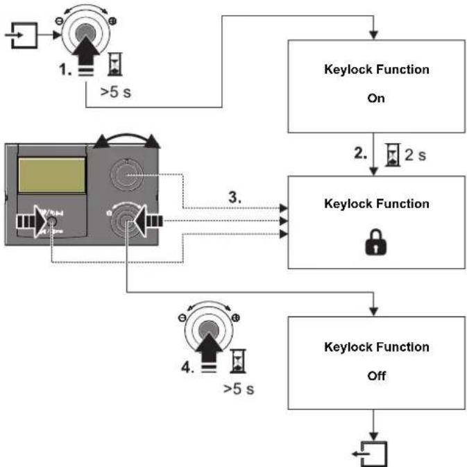
The control panel of the RoCon mb can be locked against inadvertent operation (see fig. 3-4).
It is unlocked in the same way.
Precondition for this function is that the [Keylock Function] parameter at the "Setup" level is set to "On" (see chap. 6.2.1, tab. 6-1).
flowchart
graph TD
    A["Input"] --> B{1. >5 s}
    B --> C["Keylock Function On"]
    C --> D{2. 2 s}
    D --> E["Keylock Function"]
    E --> F["Keylock Function Off"]
    F --> G["Output"]
    H["Input"] --> I{3. >5 s}
    I --> J["Keylock Function Off"]
    J --> K["Output"]
Fig. 3-4 Activating (1.) and deactivating (4.) the key lock
3.4 Basic functions and operating modes

If the storage tank temperature falls below specific minimum values, the Daikin Altherma M ECH₂O's safety settings prevent the heat pump from being operated at low outside temperatures:
- Outside temperature < -2 °C, minimum storage tank temperature = 30 °C
- Outside temperature < 12^ , minimum storage tank temperature = 23^ .
Without backup heater:
The storage tank water must be heated to the required minimum storage tank temperature with an external heater booster.
With backup heater (EKBUxx):
At an outside temperature of < 12^ and a storage tank temperature of < 35^ , the backup heater (EKBUxx) is automatically switched on to heat the storage tank water to at least 35^ .
- To speed up the heating process with backup heater, temporarily set
- parameter [Function Heating Rod] = "1" and
- parameter [Power DHW] to the maximum value of the backup heater.
- Set the rotary switch to operating mode, and set the parameter [1x Hot Water] to "On".
Automatic defrost function
At low outdoor temperatures and corresponding humidity, the heat pump outdoor unit may ice up. This icing impairs efficient operation. The system detects this status automatically and starts the defrost function.
While the defrost function is active, heat is drawn from the hot water storage tank, and the backup heater is activated if necessary. Depending on the heat required for the defrost function, heating the direct heating circuit may be temporarily interrupted during the defrosting process.
After a maximum of 8 minutes, the system switches back to normal operation.
3.4.1 System information (Info)
In this rotary switch position, the rotary button can be used to query all system temperatures, the Daikin Altherma M ECH₂O type, various software information and the operating states of all system components in succession. The number of displayed parameters depends on which components are connected.
No adjustments can be made to these values.
- Set the rotary switch to the "Info" ⓘ position.
→ Standard display is shown (see fig. 3-2). - Press the rotary button briefly.
→ Parameter overview is displayed. - Use the rotary button to select the desired information level.
- Confirm the selection with a brief push of the rotary button.
→ Value is displayed (example, see fig. 3-6). - Use the rotary button to select the individual information.
Further explanations on, and possible display values for, this rotary switch position can be found in tab. 3-5 and chap. 6.10.
Displaying the operating data overview
On the "Overview" information level, the RoCon mb controller's display shows the current operating data for the Daikin Altherma M ECHO.
The display of the operating data is split over several screen pages. Adjust the rotary button to navigate between the screen pages.
| Short designation | Explanation of the display value | |
| Page 1 | Mode | Current heat pump mode:---: No heat or cooling request☀ : Heating☀ : Cooling☀ : Hot water generation☀ : Automatic defrost function active |
| Ext | Current heat pump energy mode:LT: EVU function HT/NT active and off-peak.HT: EVU function HT/NT active and peak.SGN: EVU function Smart Grid active, normal operation.SG1: EVU function Smart Grid active, shut-off: no heat pump operation, no frost protection function.SG2: EVU function Smart Grid active, switch-on recommendation, operation at higher target temperatures, inexpensive electricity.SG3: EVU function Smart Grid active, switch-on command and storage tank charging to 70 °C, inexpensive electricity---: No external mode active, heat pump operates in standard mode. | |
| RT | Parameter [Room thermostat] / [Interlink fct]= Off: ---Parameter [Room thermostat] = On:- : Heat or cooling request- ○ : No heat requirementParameter [Interlink fct] = On (priority):- - -: Frost protection only- IL1: Normal target feed temperature- IL2:- In heating mode, increased target feed temperature- In cooling mode, reduced target feed temperature | |
| Pump | Current status of the internal heating circulation pump | |
| V | Actual flow rate in the heating system | |
| EHS | Current output of the backup heater in kW | |
| Page 2 | TV | Current feed temperature downstream of the plate heat exchanger ( t_V1 ) |
| TVBH | Current heating feed temperature, poss. downstream of the heating support heat exchanger ( t_V,BH ) | |
| TR | Current temperature of heating return ( t_R1 ) | |
| Tdhw | Current temperature in the hot water storage tank ( t_DHW ) | |
| TA | Current outside temperature (measured by the heat pump outdoor unit temperature sensor) | |
| Psyst | Current water-side pressure in the heating system | |
| Short designation | Explanation of the display value | |
| Page 3 | BPV | Current position of mixing valve 3UVB1(100% = A, 0% = B) |
| 3UVD | Current position of mixing valve 3UV DHW(100% = B, 0% = A) | |
| TA2 | Current outside temperature (measured by the optional outside temperature sensor EKRSC1) | |
| Tliq2 | Current refrigerant temperature ( t_L2 ) | |
| quiet | Indicates the whisper mode status | |
| Glycol | Glycol present: 0 (No) / 1 (Yes) | |
Tab. 3-5 Explanation of the operating data displayed as an overview

flowchart
graph TD
    A["Weather Panel"] --> B["01.04.13 13:36"]
    B --> C["Mode: Pumps On"]
    C --> D["Ext: V: 1205 l/h"]
    D --> E["RT: EHS: 3 kW"]
    E --> F["Mode: Pump On"]
    F --> G["TV: 42°C Tdhw: 48°C"]
    G --> H["TVBH: 44°C TA: 1°C"]
    H --> I["TR: 36°C Psyst: 1.9 bar"]
    I --> J["Mode: Tlq2: 46°C"]
    J --> K["BPV: 0% Tliq2: 46°C"]
    K --> L["3UVD: 0% quiet: On"]
    L --> M["TA2: 2°C Glycol: 0"]
    M --> N["Mode: Quiet: On"]
    N --> O["(a), (b)"]
Fig. 3-5 Displaying the operating data overview

At low return flow temperatures and with glycol in the system, only "ffff" is displayed as the volumetric flow, no current value.
3 Operation
Displaying the water pressure
On the RoCon mb control unit, the system pressure (water pressure) of the internal circuit (direct heating circuit) can be displayed when it is switched on. The water pressure is the first info parameter available after the operating data overview (see fig. 3-6).
The permissible water pressure range during operation is dependent on the Daikin Altherma M ECHO and the heating system. The target values and thresholds may only be set by the heating expert. If the water pressure drops below the minimum value (set parameter value), it must be increased by topping up the system (see Daikin Altherma M ECHO installation instructions, chapter entitled "Inspection and maintenance").

The pressure limits for safety shut-off and the target pressure can be set in the parameter setting on the "System Configuration" level.

flowchart
graph TD
    A["Sensor 1"] --> B["01.04.13"]
    B --> C["13:36"]
    C --> D["33.0°C"]
    C --> E["13.4°C"]
    C --> F["48.0°C"]
    D --> G["2x Exit / Home"]
    E --> G
    F --> G
    G --> H["Water Pressure T-HS"]
    H --> I["2,5 bar"]
    I --> J["(a), (b)"]
    K["Info"] --> H
    L["Overview"] --> H
    M["Exit / Home"] --> I
Fig. 3-6 Displaying info values (e.g. system pressure)
3.4.2 Setting the operating mode
The operating mode in which the Daikin Altherma M ECH₂O is to operate is selected using the rotary switch in the "Operating Mode" ⏻...♦ position.
The selected operating mode is activated by briefly pressing the rotary button.

flowchart
graph TD
    A["Operating Mode"] --> B["Operating Mode"]
    B --> C["Operating Mode"]
    C --> D["Operating Mode"]
    D --> E["Operating Mode"]
    style A fill:#f9f,stroke:#333
    style B fill:#ccf,stroke:#333
    style C fill:#cfc,stroke:#333
    style D fill:#fcc,stroke:#333
    style E fill:#ffc,stroke:#333
Fig. 3-7 Changing the operating mode (e.g. from "Standby" to "Automatic 1")
- Set the rotary switch to the "Operating Mode" ⏻... Position.
→ An overview is displayed. - Use the rotary button to select the required operating mode.
- Confirm the selection with a brief push of the rotary button.
→ Daikin Altherma M ECH₂O operates according to the set operating mode.
→ The current operating mode is indicated by an appropriate symbol on the standard display.
Operating mode Standby (Stand-by)

CAUTION!
A heating system that is not protected against frost can freeze in the event of frost and thus be damaged.
- Add glycol to the heating water circuit (see installation and maintenance instructions)
- Alternatively, drain the heating system on the water side if there is a danger of frost.
- If the heating system is not drained, the power supply must be ensured and the external main switch must remain switched on if there is a danger of frost.
In this operating mode, the Daikin Altherma M ECHO is switched to Stand-by mode. The frost protection function (see chap. 3.6.5) is maintained. In order to maintain this function, the system may not be disconnected from the mains.
All controllers integrated in the RoCon system via the CAN bus are primarily also switched to the "Standby" operating mode.

Fig. 3-8 Standard display in the "Standby" operating mode (above the frost limit temperature)
Operating mode Reducing
Reduced heating mode (lower target room temperature) according to the target feed temperature set for reducing mode in the parameter [T-Reduced] (see chap. 3.4.4).
Hot water preparation according to the set target hot water temperatures and switching cycles in the hot water time program [DHW Program 1] (see chap. 3.4.5).
Heating, Cooling
Heating, cooling mode according to the target room temperature set in the parameter [T-Room 1 Setpoint] (see chap. 3.4.3).
A connected outside temperature sensor (weather-dependent T-HS control) or a connected room station also influence the target feed temperature (prerequisite: parameter [HC Function] = On).
Hot water preparation according to the set target hot water temperatures and switching cycles in the hot water time program [DHW Program 1] (see chap. 3.4.5).
Operating mode Summer
Hot water preparation according to the set target hot water temperatures and switching cycles in the hot water time program [DHW Program 1] (see chap. 3.4.5).
All controllers integrated in the RoCon system via the CAN bus are primarily also switched to the "Summer" operating mode.
Operating mode Automatic 1 (time program)
Automatic heating and setback mode according to the permanent time programs (see chap. 3.4.7):
- [HC Program 1]
- [DHW Program 1]
Operating mode Automatic 2 (time program)
Automatic heating and setback mode according to the permanent time programs (see chap. 3.4.7):
- [HC Program 2]
- [DHW Program 2]

If the hot water readiness is in setback mode in the active operating mode, a temporary "DHW Reheating" can be set with the rotary switch setting without having to change other standard settings (see 3.4.6).

Switching contact for external operating mode switch-over
A potential-free switching contact connected via Daikin Altherma M ECH _2 O connection J8 at the "EXT" terminals and wired with a resistor can also be used to switch the operating mode from an external device (e.g. modem, ...).
In this case, the switching contact functionality is dependent on the parameter [Function BSC]:
- [Function BSC] = 0 (default setting): evaluation of the resistance values (see tab. 3-6)
- [Function BSC] = 1: evaluation as a burner blocking contact. If the switching contact is closed, the external heat generator has priority.
| Operating mode | Resistance | Tolerance |
| Standby | < 680 Ω | ±5 % |
| Heating | 1200 Ω | |
| Reducing | 1800 Ω | |
| Summer | 2700 Ω | |
| Automatic 1 | 4700 Ω | |
| Automatic 2 | 8200 Ω |
Tab. 3-6 Resistance values for evaluating the EXT signal

The resistances specified in tab. 3-6 function in a tolerance field of 5%. Resistances outside this tolerance field are interpreted as an open input. The heat generator switches back to the previously active operating
mode.
The input is not considered for resistance values greater than the value for "Automatic 2".
If several switching contacts are to be connected to the Daikin Altherma M ECH _2 O (e.g. Smart Grid, room thermostat), the related functions may have a higher priority than external operating mode switch-over. The operating mode requested by the EXT switching contact is then possibly not activated, or is only activated later.
Besides these operating modes, different temporary heating programs (see tab. 3-7) are available that are carried out with priority after activation.
| Temporary time program | Setting/Activation in the level | Rotary switch setting | Information |
| DHW Install | DHW Install | Chap. 3.4.6 | |
| Party | Time Program | Chap. 3.4.7 | |
| Away | |||
| Holiday | |||
| Vacation | |||
| Screed* | Configuration > HC Configuration | Chap. 3.6.13 |
* only with technician code.
Tab. 3-7 Overview of temporary time programs

If a temporary time program (DHW Install, Party, Away, Holiday, Vacation, Screed) is started during the selected operating mode, control is carried out primarily according to the settings for this time program.
3.4.3 Temperature setting of daytime room temperature
In rotary switch position the target room temperatures during the day for room heating are defined.
- Set the rotary switch to the "Set Temp Day" position.
→ An overview is displayed.

The last digits of the parameter designations (1 - 3) within this rotary switch setting mark the affiliation to the respective cycle of the time program.
- Select the temperature block to be set with the rotary button.
- Confirm the selection with a brief push of the rotary button.
→ Settings are displayed. - Set the temperature.
- Confirm the selection with a brief push of the rotary button.
→ Change has been accepted. Jump back to previous display.
Detailed explanations and possible setting values for this rotary switch setting can be found in chap. 6.5.
3.4.4 Temperature setting of setback mode
In rotary switch position the target room temperatures in reducing mode for room heating are defined.
- Set the rotary switch to the "Set Temp Night" position.
→ An overview is displayed. - Select the parameter to be set with the rotary button.
- Confirm the selection with a brief push of the rotary button.
– [T-Reduced]: Setting value for "Reducing" operating mode or reduction through permanent time program.
– [T-Absence]: Setting value for temporary heating/cooling programs ("Away" and "Vacation").
→ Settings are displayed.
- Set the temperature.
- Confirm the selection with a brief push of the rotary button.
→ Change has been accepted. Jump back to previous display.
Detailed explanations and possible setting values for this rotary switch setting can be found in chap. 6.6.
3.4.5 Temperature setting of hot water generation
In rotary switch position the target hot water temperatures for hot water preparation for the respective time programs are defined.
- Set the rotary switch to the "DHW Set Temp" position.

The last digits of the parameter designations (1 - 3) within this rotary switch setting mark the affiliation to the respective cycle of the time program.
- Select the temperature block to be set with the rotary button.
- Confirm the selection with a brief push of the rotary button.
→ Settings are displayed.
- Set the temperature.
- Confirm the selection with a brief push of the rotary button.
→ Change has been accepted. Jump back to previous display.
Detailed explanations and possible setting values for this rotary switch setting can be found in chap. 6.7.
3.4.6 Unscheduled hot water preparation
In rotary switch position the hot water can be recharged manually, outside of a hot water time program, to the target temperature set as default in the parameter [T-DHW Setpoint 1]. The heating up is carried out with priority and independent of other heating programs.
- Set the rotary switch to the "DHW Install" position.
→ An overview is displayed. - Select the parameter to be set with the rotary button.
– [1x Hot Water]: Activation of one-time hot water generation. - Confirm the selection with a brief push of the rotary button.
- Set the parameter.
- Confirm the selection with a brief push of the rotary button.
→ The unscheduled hot water generation starts.

After this temporary function has elapsed, the control unit automatically jumps back to the previously active operating mode. The rotary switch should therefore be brought back into the "Info" ⓘ position after the
function has been activated.
The function is subject to time limitations.
At the latest, it is cancelled after the maximum loading time set in the parameter [Max DHW loading time], and can be restarted at the earliest after the blocking time set in the parameter [DHW Off Time] has expired (see chap. 6.2.4).
Detailed explanations and possible setting values for this rotary switch setting can be found in chap. 6.3.
3.4.7 Switching time program
For comfortable and individual room and hot water temperature control, different (but freely adjustable) time programs preset at the factory can be selected.
The switching time programs control the assigned heating circuit, the storage charging circuit as well as an optionally connected circulation pump according to the specified switching times.
Setting
In the switch setting, the time intervals for the heating circuit, integrated hot water generation and the optional circulation pump are set.
- Set the rotary switch to the "Time Program" Ⓞ ∩ ∩ position.
→ An overview is displayed. - Use the rotary button to select the time program to be set.
- Confirm the selection with a brief push of the rotary button.
→ Settings are displayed. - Use the rotary button to select and change the value to be adjusted.
- Confirm the selection with a brief push of the rotary button.
More detailed explanations and possible setting values for this rotary switch position can be found in chap. 6.8.
Permanent time programs
Time programs control the heating circuit temperatures or the operating times of the circulation pump according to the specified switching cycles for the connected heating circuits and the storage charging circuit. The switching cycles are saved in time blocks for which different target temperatures can be set.
In the switching cycles, the heating system is controlled differently according to day and reducing mode.
The target temperatures for these time programs are set in the rotary switch positions "Set Temp Day" ⚙, "Set Temp Night" ⚙ and "DHW Set Temp" ⚙
The following switching time programs are available:
- 2 time programs for the heating circuit, each with 3 possible switching cycles
– [HC Program 1]
- [HC Program 2]

The times can be entered separately for each individual weekday or in blocks of "Monday to Friday", "Saturday to Sunday" and "Monday to Sunday".

flowchart
graph TD
    A["HC Program 1"] --> B["Individual weekday (Monday, Tuesday ...)"]
    A --> C["Working week (Monday to Friday)"]
    A --> D["Weekend (Saturday to Sunday)"]
    A --> E["Whole week (Monday to Sunday)"]
    F["HC Program 2"] --> G["See HC Program 1"]
    B --> H["1. 06:00 --> 22:00\n2. --:---> --:--\n3. --:---> --:--"]
    C --> I["1. 06:00 --> 22:00\n2. --:---> --:--\n3. --:---> --:--"]
    D --> J["1. 07:00 --> 23:00\n2. --:---> --:--\n3. --:---> --:--"]
    E --> K["1. 06:00 --> 22:00\n2. --:---> --:--\n3. --:---> --:--"]
    G --> L["1. 2. 2. 3. See HC Program 1"]
Tab. 3-8 Menu structure of heating circuit/time program

Time settings for a switching cycle in a weekday or block program will also be accepted for other time periods as long as they are for the same weekdays. Examples referring to tab. 3-8:
a) The starting time in the 1st switching cycle is changed from 06:00 am to 05:00 am for the individual weekday "Monday".
→ The 1st switching cycle is also automatically changed from 06:00 am to 05:00 am for the "working week" and "whole week" time periods.
b) The starting time in the 1st switching cycle is changed from 07:00 am to 08:00 am for the "weekend" time period.
→ The 1st switching cycle is also automatically changed from 07:00 am to 08:00 am for the individual weekdays "Saturday" and "Sunday".
c) The end time in the 1st switching cycle is changed from 10:00 pm to 9:30 pm for the "whole week" time period.
→ The 1st switching cycle is also automatically changed from 10:00 pm to 9:30 pm in all weekday or block programs.
- 2 time programs for the hot water circuit, each with 3 possible switching cycles
- [DHW Program 1]
– [DHW Program 2]

The setting and the entry structure of the time programs are identical with those for the heating circuit time program (see also tab. 3-8).
- 1 time program for an optionally connected circulation pump, each with 3 possible switching cycles
- [Circulation Time]

The setting and the entry structure of the time program are identical with those for the heating circuit time program (see also tab. 3-8).
For further information on settings for an optional circulation pump, see chap. 3.6.15.
Saved switching time programs can be changed at any time. For a better overview, it is recommended to write down and safely store the programmed switching cycles (see chap. 9.1.1).
The permanent time programs are preset according to tab. 3-9.
3 Operation
| Switching cycle 1 Switching cycle 2 Switching cycle 3 | ||||||
| Time period On Off | On Off On Off | |||||
| Room heating | ||||||
| Temperature setting | [T-Room 1 Setpoint]: 20 °C [T-Room 2 Setpoint]: 20 °C [T-Room 3 Setpoint]: 20 °C | |||||
| [T-Reduced]: 10 °C | ||||||
| "HC Program 1" | ||||||
| Monday - Friday 06:00 | 22:00 - : - - - : | - - - - : - - - : - | ||||
| Saturday, Sunday 07:00 | 23:00 - : - - - : | - - - - : - - - : - | ||||
| "HC Program 2" | ||||||
| Monday - Friday 06:00 | 08:00 - : - - - : | - - - - : - - - : - | ||||
| Saturday, Sunday 07:00 | 23:00 - : - - - : | - - - - : - - - : - | ||||
| Domestic hot water generation | ||||||
| Temperature setting | [T-DHW Setpoint 1]: 48 °C [T-DHW Setpoint 2]: 48 °C [T-DHW Setpoint 3]: 48 °C | |||||
| "DHW Program 1" | ||||||
| Monday - Sunday | 00:00 24:00 | - - : - - - : - - - : - - - : - | ||||
| "DHW Program 2" | ||||||
| Monday - Friday 05:00 | 21:00 - : - - - : | - - - - : - - - : - | ||||
| Saturday, Sunday 06:00 | 22:00 - : - - - : | - - - - : - - - : - | ||||
| "Circulation Time" | ||||||
| Monday - Friday 05:00 | 21:00 - : - - - : | - - - - : - - - : - | ||||
| Saturday, Sunday 06:00 | 22:00 - : - - - : | - - - - : - - - : - | ||||
Tab. 3-9 Factory setting of the permanent switching time programs
Temporary time programs
4 temporary time programs are available for special situations, which make the permanent time programs or the currently set operating mode ineffective for the duration of their validity.
The symbol of the temporary time program is displayed in the header of the standard display for as long as the time program is active.

The following temporary time programs can be cancelled at any time due to the manual changing of the operating mode.
- [Party]: Immediate one-off extension of room heating.
a) If an automatic program is activated, the last valid switching cycle is always extended. In the time prior to switching cycle 1, control is carried out according to the target room temperature set in the parameter [T-Room 1 Setpoint].
b) In all other operating modes, control is carried out according to the target room temperature set in the parameter [T-Room 1 Setpoint].
- The hot water generation is not affected.
- The time program runs for the set time period from activation.
-
[Away]: Immediate one-time setback up to 6
-
In reducing mode, control is carried out according to the target room temperature set in the "Set Temp Night" rotary switch position in the parameter [T-Absence].
– The hot water generation is not affected. -
The time program runs for the set time period from activation.
-
[Holiday]: One-time calendar-controlled presence.
-
Control is carried out only according to the settings for "Sunday" in the [HC Program 1].
-
The hot water generation is only controlled according to the settings for "Sunday" in the [DHW Program 1].
-
[Vacation]: One-time calendar-controlled setback.
-
In reducing mode, control is carried out exclusively according to the target room temperature set in the "Set Temp Night" rotary switch position in the parameter [T-Absence].
- Hot water generation according to the set target temperatures and switching cycles in the [DHW Program 1] hot water time program (see chap. 3.4.5).
- The calendar-controlled [Vacation] program is not started if the "Standby" or "Manual Operation" operating mode is active on the set start date.
3.4.8 System settings
In the "Configuration" rotary switch position, basic setting of the RoCon mb controller and system configuration for the installation environment of the Daikin Altherma M ECH₂O, the direct heating circuit, hot water preparation and any optionally connected components are carried out.
Depending on the access authorisation (user or expert), different parameters are available. Several parameters can only be accessed by the heating expert.
Setting the LCD display, language, date, time

An internally pre-programmed calendar ensures an automatic timeshift for the annually repeating summertime/wintertime changeover dates.
- Set the rotary switch to the "Configuration" position.
→ An overview is displayed. - Use the rotary button to select the "Setup" level.
→ An overview is displayed. - With the rotary button, select the parameters [LCD Brightness] and [LCD Illum Time], and change them if desired.
- With the rotary button, select and confirm the parameters [Language], [Date] or [Time].
- Use the rotary button to select and change the value to be changed within the respective display.
- Confirm the selection with a brief push of the rotary button.
→ Change has been accepted. Jump back to previous display.
Detailed explanations and possible setting values of this rotary switch setting can be found in chap. 3.6 and in chap. 6.2.
3.4.9 Terminal function
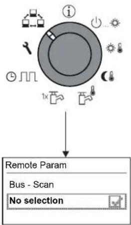
In the "Remote Param" rotary switch setting, other devices (mixer module control unit or heat generator control components) integrated in the RoCon system via the CAN bus can also be operated and parametrised as long as the respective control unit has the required authorisation (see also chap. 4.3).
A list of the recognised devices is displayed for selection on the display after activation of the "Bus - Scan" (external devices and local device).
After selection and confirmation of an external device, the terminal function for this device is activated and the associated standard display for this device is shown on the display.
The operating component is then in terminal operation.
flowchart
graph TD
    A["Remote Param"] --> B["Bus - Scan"]
    B --> C["No selection"]
Fig. 3-9 Display of the "Remote Param" level during commissioning or after interim disconnection from the mains
The local control unit functions as a remote control for the external device. In this case, all the control functions are performed and saved 1:1 as on the external device.
The different application and parametrisation options for the use of the devices and control units in the RoCon system connected via the CAN bus are described in chap. 4.3.

flowchart
graph TD
    A["WE1"] --> B["B1"]
    B --> C["H1"]
    B --> D["H2"]
    C --> E["Bus"]
    D --> F["U1"]
    E --> G["M1"]
    F --> G
    G --> H["Remote Param"]
    H --> I["Bus - Scan"]
    I --> J["No selection"]
    J --> K["2."]
    K --> L["Remote Param"]
    L --> M["Bus - Scan"]
    M --> N["No selection"]
    N --> O["3."]
    O --> P["4."]
    P --> Q["Remote Param"]
    Q --> R["No selection"]
    R --> S["Contr BM1/BE1 #X"]
    S --> T["Mix Valve #X"]
    T --> U["Remote Param"]
    U --> V["Contr BM1/BE1 #X"]
    V --> W["Mix Valve #X"]
    W --> X["7."]
    X --> Y["01.04.13 13:36"]
    Y --> Z["24.5°C 9.6°C"]
B1 RoCon B1 control panel of the Altherma M ECH₂O
Bus CAN bus (connection line between RoCon devices and control units)
H_1 Direct heating circuit (e.g. radiators)
H_2 Mixed heating circuit (e.g. floor heating)
M1 EHS157068 mixer module
U1 EHS157034 room station
WE1 Heat generator Altherma M ECH₂O
Fig. 3-10 Example of "Bus - Scan" on a heating system with 1 heat generator, 1 mix valve, 1 room station and activation of the terminal function for remote control of the mixer module
3 Operation
If the terminal function is activated, the #X symbol is displayed in the header of the display as additional information on the remote-controlled device, where "X" is the set device identification of the remote-controlled device.
The displayed values and symbols are always accepted by the selected device (e.g. mixer circuit T-HS of the EHS157068 mix valve module with device identification 1).
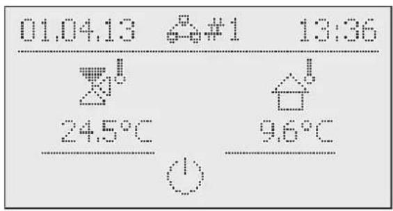
Fig. 3-11 Example of the display for the remote-controlled mixer module
In order to operate the local device, it must be activated again in the selection list ([No selection] parameter).

If the "n.A." message is displayed in the rotary switch setting 📄, no valid terminal ID has been assigned to the control unit until now.
If the "n.A." message is still displayed, it may be necessary to update the device software in order to use the terminal function. Contact the Daikin Service Team for this.
Activating/deactivating terminal operation
Prerequisite: a valid terminal ID has been assigned to the RoCon B1 control panel of the Daikin Altherma M ECH₂O or the EHS157034 room station.

For setting the terminal ID of optionally connected devices, see chap. 4.4 or the respective operating instructions that are supplied.
- Set the rotary switch to the "Remote Param" position.
→ The "Remote Param" level is displayed.

- Use the rotary button to select the [Bus - Scan] parameter.
- Confirm the selection with a brief push of the rotary button.
→ The context menu is displayed.
- Use the rotary button to select the [Bus - Scan] parameter and confirm with "Yes".
→ Bus - Scan is performed.
→ An overview of all the devices found is displayed (for an example, see fig. 3-10).
- Use the rotary button to select the device for which the terminal function should be carried out.
- Confirm the selection with a brief push of the rotary button.
→ The local control unit functions as a remote control for the external device.
To end terminal operation and to switch back to the control unit for the operation of the assigned device, the [No selection] parameter must be selected and confirmed at the "Remote Param" level.

After an interim disconnection from the power supply, the display always appears at the "Remote Param" level, as shown in fig. 3-9.
To be able to use the terminal function for connected devices, a repeat Bus - Scan must be carried out.
Communication between the RoCon system components also continues to function without a Bus - Scan, and previously undertaken settings remain active.
The terminal function is activated as shown in fig. 3-10, but after confirmation of the "Bus - Scan" display, the [New scan?] parameter must be selected with the rotary button and confirmed with "Yes".
3.4.10 Operation with glycol
Frost can damage the system. To prevent the hydraulic components from freezing, the software is equipped with special frost protection functions, that include the activation of pump, internal heaters, and/or backup heater operation in case of low temperatures.
However, in case of a power failure, these functions cannot guarantee protection. It is therefore recommended to add glycol to the water circuit. To do this, observe the installation and maintenance instructions.
If glycol has been added to the system, the RoCon controller setting must be adapted accordingly.
- Set the rotary switch to the "Configuration" position.
→ An overview is displayed.
- Use the rotary button to select the "Setup" level.
→ An overview is displayed.
- Use the rotary button to select the [Glycol] parameter.
- Change the parameter if desired.
- Parameter [Glycol] = 0: no glycol added
- Parameter [Glycol] = 1: glycol added
- Confirm the selection with a brief push of the rotary button.
→ Change has been accepted. Jump back to previous display.
3.4.11 Whisper mode
Whisper mode means that the heat pump outdoor unit operates at reduced output. This reduces the operating noise generated by the heat pump outdoor unit.

CAUTION!
During active whisper mode, the output in room heating and room cooling mode decreases such that it may no longer be possible to achieve pre-set target temperature values.
- With outside temperatures below freezing, there is a risk of material damage caused by frost.
Activating / deactivating whisper mode
- Set the rotary switch to the "Configuration" position.
→ An overview is displayed.
- Use the rotary button to select the "System Configuration" level.
→ An overview is displayed.
- Use the rotary button to select the [Quite Mode] parameter.
- Confirm the selection with a brief push of the rotary button.
→ The setting of the parameter is displayed.
- Set the parameter.
- Parameter [Quite Mode] = 0: deactivated
- Parameter [Quite Mode] = 1: permanently activated
- Parameter [Quite Mode] = 2: only activated at night
- Confirm the selection with a brief push of the rotary button.
→ Change has been accepted. Jump back to previous display.
Detailed explanations and possible setting values of this function can be found in chap. 6.2.2.
3.4.12 Smart Grid (SG)

WARNING!
There is a danger of scalding at target hot water temperatures over 60 °C. This is possible, as the utility company (EVU) is entitled to control current draw optimised according to supply and demand in the definitions for Smart Grid.
Due to such forced charging, the target hot water temperature in the hot water storage tank can exceed 60 °C.
This storage tank charging is carried out even when "Standby" operating mode is set.
- Install scald protection in the hot water distribution line (e.g. VTA32 + Screw set
A special electricity meter with SG receiver, to which the Daikin Altherma M ECH _2 O must be connected, is required to use this function.
As soon as the function is activated by the parameter [SMART GRID] = 1, the heat pump is set to an operating mode as per tab. 3-10 depending on the utility company signal.
| Signal^2) | Electric-ity costs | Effect on | ||
| EVU | SG | Domestic hot water | Heating installa-tions | |
| 1 | 0 | --- | No operation^1) | No operation^1) |
| 0 | 0 | Normal | Normal operation | Normal operation |
| 0 | 1 | Low | Switch-on recom-mendation, and tar-get storage tank temperature value is increased depending on the parameter [Mode SG] | Switch-on recom-mendation, and tar-get feed temperature is increased depend-ing on the parameter [Mode SG] |
| 1 | 1 Very low Switch | on command, and target storage tank temperature val-ue is set to 70 °C | Switch-on command for storage tank charging | |
1) No frost protection function (see chap. 3.6.5).
2) Switching contacts at input J8 of the RoCon BM1 printed circuit board closed (1) or opened (0).
Tab. 3-10 Use of the SG signal
Detailed explanations and possible setting values of this function can be found in chap. 6.2.1.
3.4.13 EHS emergency operation
If the heat pump fails, the backup heater can be used as emergency heating, and can undertake all heating requirements either automatically or non-automatically.

Activation of emergency automatic operation ensures that heating and hot water requirements are reliably met even if the heat pump fails. However, the risk is run that the user only notices the system malfunction after a certain time, and that electricity consumption is thus increased.
If emergency automatic operation is deactivated (default setting), it must be activated as described below to meet heating and hot water requirements in the event that the outdoor unit fails.
Activating / deactivating emergency automatic operation
- Set the rotary switch to the "Configuration" position.
→ An overview is displayed. - Use the rotary button to select the "Setup" level.
→ An overview is displayed. - Use the rotary button to select the [Emergency BUH] parameter.
- Confirm the selection with a brief push of the rotary button.
→ The setting of the parameter is displayed. - Set the parameter.
- Parameter [Emergency BUH] = 0: no automatic emergency operation
- Parameter [Emergency BUH] = 1: automatic emergency operation
- Confirm the selection with a brief push of the rotary button.
→ Change has been accepted: Jump back to previous display.
3 Operation
3.5 Special functions
At the "Special Level", different functions (mostly useful functions for the heating expert) can be carried out.
The following special functions are possible:
– Manual operation (see chap. 3.5.1).
- Displaying messages (see chapter 7)
- Reset to factory settings (see chap. 3.6.12)
Detailed explanations of these functions can be found in chap. 6.11.

The calling-up of the special functions does not depend on the rotary switch setting.
- Push the Exit button for at least 5 s.
→ Menu "Special Level" is displayed.
- Use the rotary button to select the program to be started.
- Confirm the selection with a brief push of the rotary button.
→ The selected program starts.
• Cancellation and jump back by:
- pressing the Exit key again or
- touching the rotary button or
- selecting another menu using the rotary switch.
3.5.1 Manual operation
Manual operation is used to manually control the Daikin Altherma _2 MEc specific feed temperature. Manual operation should only be used for diagnostic purposes.
With hydraulically controlled priority operation for hot water preparation, it must be ensured that the target feed temperature set in manual mode is sufficient to achieve the stored target hot water temperature (parameter [T-DHW Setpoint 1]).
- Push the Exit button for at least 5 s.
→ Menu "Special Level" is displayed.
- Use the rotary button to select the "Manual Operation" program.
- Confirm the selection with a brief push of the rotary button.
→ "Manual Operation" is active.
- Use the rotary button to set the target feed temperature.

Do not confirm this setting with the rotary button, as the program is otherwise ended.
→ During active manual mode, the storage tank temperature is permanently regulated to the first target hot water temperature parameter value ([T-DHW Setpoint 1]).
The key lock (if it was activated prior to the start of this function) is reactivated within 2 s to prevent undesired cancellation of the function through operation of the RoCon mb controller.
• Cancellation and jump back by:
- pressing the Exit key again or
- touching the rotary button or
- selecting another menu using the rotary switch.
→ If manual operation is ended, the RoCon mb control unit automatically switches to "Standby" operating mode.

flowchart
graph TD
    A["Start"] --> B["Special Level"]
    B --> C["Manual Operation FA failure"]
    C --> D["Manual Operation"]
    D --> E["Set Point 60.0 °C 20 °C Current Value 55.0 °C 80 °C"]
    E --> F["Attention! Actual mode: 2 s"]
    F --> G["End"]
    style A fill:#f9f,stroke:#333
    style G fill:#ccf,stroke:#333
Fig. 3-12 Symbolic brief instructions for manual operation
3.5.2 3-way switching valves reference travel
The positions of the two 3-way switch valves 3UVB1 and 3UV DHW in the Daikin Altherma M ECH₂O are controlled continuously between their two basic settings for optimised energy utilisation (e.g. heating support function).
To ensure this function, the two 3-way switch valves are always moved automatically to their basic position (bypass - path AB-A open) at 11:00 hours.
This function can take up to 5 minutes. It is programmed as standard and cannot be changed.
3.6 Special system settings
The RoCon mb controller is already basically configured for the Daikin Altherma M ECHO. However, it must still be adapted to optionally connected accessories and the installation environment during initial commissioning.
The adjustment is carried out by setting the parameters in the "Configuration" rotary switch setting.
The next lowest level can be accessed or the respective parameter directly accessed by navigation with the rotary button.
3.6.1 Access rights (technician code)
Certain settings in the control unit are limited by access rights. To receive access to these parameters, the technician code must be entered at the "Setup" level.
Fig. 3-13 shows the basic procedure for entering the access code. The expert company receives the technician code in a separate letter.

flowchart
graph TD
    A["Configuration"] --> B["System Configuration"]
    B --> C["Setup"]
    C --> D["Language"]
    D --> E["Setup"]
    E --> F["Keylock Function"]
    F --> G["Access Rights"]
    G --> H["Outdoor type"]
    H --> I["Access Rights"]
    I --> J["0 0 0 0"]
    J --> K["2 s"]
    L["Access Rights"] --> M["User"]
    M --> N["Access Rights"]
    N --> O["Expert"]
    O --> P["Access Rights"]
    P --> Q["✓"]
    Q --> R["2 s"]
    S["[0 ... 9"]] --> T["3x"]
    T --> M
Fig. 3-13 Entering the access code
3.6.2 Heat slope

Caution - Risk of overheating of floor heating!
In the event of malfunction or during manual operation, the floor heating, the screed or the floor structure could be damaged due to overheating.
- Prior to initial commissioning of the floor heating system, set the maximum temperature limit in the RoCon mb controller (parameter [T vbh1 max]) and the maximum permissible system temperature (parameter [Max T-Flow]).
- Connect an overheating protection switch (in the building) at the "EXT" plug connection to external operating mode switch-over so that the Daikin Altherma _2 ME Switched to "Standby" or "Summer" operating mode (see chap. 3.4.2).
With parameter [Room thermostat] = On or parameter [Interlink fct] = On, the overheating protection switch must be connected so that the room thermostat's switching contact is interrupted.
- If the floor heating is also used for room cooling, the connection notes in the above point also apply to the connection of a moisture protection switch in the building.
The heat slope is used to adjust the target feed temperature to the characteristics of the building depending on the respective outside temperature (weather-dependent T-HS control, see chap. 3.6.4). Generally speaking, the steepness of the heating slope describes the ratio of the T-HS change to the external temperature change.
The heat slope is valid within the limits of the minimum and maximum temperatures set for the respective heating circuit. Deviations may occur between the room temperature measured in the occupied area and the desired room temperature; these can be minimised by installing a room station or a room thermostat.
The control unit is set at the factory in such a way that the heat slope does not independently adjust itself during operation.
Automatic heat slope adaptation can be activated (parameter [HC Adaption]), if the room station (EHS157034) is connected (see chap. 3.6.4).
Start conditions for automatic heat slope adjustment:
- Outside temperature < 8^
- Operating mode is automatic (I or II)
– Duration of the setback period is at least 6 h
If no automatic heat slope adjustment is activated, the heat slope can be manually adjusted by adjusting the [Heat-Slope] parameter).

Manually adjusting the heat slope
Do not make any corrections to the set values for 1 - 2 days, and then only make them in small increments.
- Deactivate the external heat sources (e.g. stoves, direct sunlight, open windows).
- Fully open any radiator thermostat valves or actuators.
- Activate "Heating" operating mode.
Approximate setting values:
- Radiators: 1.4 to 1.6.
– Floor heating: 0.5 to 0.9.

flowchart
graph TD
    A["Configuration"] --> B["Setup"]
    B --> C["System Configuration"]
    C --> D["Configuration"]
    D --> E["System Configuration"]
    E --> F["HC Configuration"]
    F --> G["DHW Configuration"]
    G --> H["HC Configuration"]
    H --> I["HC Function"]
    I --> J["T-Frost Protect"]
    J --> K["HC Configuration"]
    K --> L["Insulation"]
    L --> M["Heating"]
    M --> N["Cooling"]
    N --> O["1."]

    P["Heating"] --> Q["T-Outside lim night"]
    Q --> R["Heat-Slope"]
    R --> S["Room Influence"]
    S --> T["Heat-Slope 0.50 0.0 3.00"]
    T --> U["Heat-Slope 0.80 0.0 3.00"]
    U --> V["Heat-Slope ✓ 2 s"]

    style A fill:#f9f,stroke:#333
    style P fill:#ccf,stroke:#333
Fig. 3-14 Manual setting of the heat slope (illustration with "User" access authorisation)

line
| TA (°C) | TV (°C) for 0.2 | TV (°C) for 0.4 | TV (°C) for 0.6 | TV (°C) for 0.8 | TV (°C) for 1.0 | TV (°C) for 1.3 | TV (°C) for 1.5 | TV (°C) for 2.0 | TV (°C) for 2.5 | TV (°C) for 3.0 | |---------|-----------------|-----------------|-----------------|-----------------|-----------------|-----------------|-----------------|-----------------|-----------------|-----------------| | 20 | 30 | 30 | 30 | 30 | 30 | 30 | 30 | 30 | 30 | 30 | | 15 | ~35 | ~37 | ~40 | ~43 | ~46 | ~50 | ~55 | ~60 | ~65 | ~70 | | 10 | ~40 | ~45 | ~50 | ~55 | ~60 | ~65 | ~70 | ~75 | ~80 | ~85 | | 5 | ~45 | ~50 | ~55 | ~60 | ~65 | ~70 | ~75 | ~80 | ~85 | ~90 | | 0 | ~50 | ~55 | ~60 | ~65 | ~70 | ~75 | ~80 | ~85 | ~90 | ~95 | | -5 | ~55 | ~60 | ~65 | ~70 | ~75 | ~80 | ~85 | ~90 | ~95 | ~100 | | -10 | ~60 | ~65 | ~70 | ~75 | ~80 | ~85 | ~90 | ~95 | ~100 | ~105 | | -15 | ~65 | ~70 | ~75 | ~80 | ~85 | ~90 | ~95 | ~100 | ~105 | ~110 | | -20 | ~70 | ~75 | ~80 | ~85 | ~90 | ~95 | ~100 | ~105 | ~110 | ~115 |T_A Outside temperature
T_V T-HS
T_R Room temperature target value
Fig. 3-15 Heat slopes
Detailed explanations and possible setting values of this function can be found in cheap.
3.6.3 Cooling slope

Caution - risk of condensation!
In the event of malfunction or incorrect parameter settings, the floor heating, the screed or the floor structure could be damaged due to condensation.
- Prior to initial commissioning and activation of cooling mode, set the minimum temperature limit to the minimum permissible system temperature in the RoCon mb controller (parameter [Min T-Flow Cooling]).
The cooling slope is used to adjust the target feed temperature to the characteristics of the building depending on the respective outside temperature (weather-dependent T-HS control, see chap. 3.6.4). Warmer outside temperatures result in a colder target feed temperature and vice versa.
Prerequisites for cooling mode:
- Outside temperature > set target room temperature value
- Outside temperature > set value of the parameter [Start T-Out Cooling]
- "Cooling" operating mode activated.
a) Via rotary switch in "Operating Mode" ⏻... position or b) via room thermostat function (cooling ⚙️ switching contact closed)
- No heat request active in the heating system's RoCon system.
The cooling slope is defined through the four following parameters:
- [Start T-Out Cooling]
- [Max T-Out Cooling]
- [T-Flow Cooling start]
- [T-Flow Cooling max]
During weather-dependent T-HS control, the user can increase or decrease the target feed temperature by a maximum of 5 K with the parameter [Cooling Setpoint adj]. A temperature reduction is limited by the parameter [Min T-Flow Cooling].

area
| TA | T> | |----|----| | 1 | 3 | | 6 | 3 | | 2 | 4 |1 Parameter [Start T-Out Cooling]
2 Parameter [Max T-Out Cooling]
3 Parameter [T-Flow Cooling start]
4 Parameter [T-Flow Cooling max]
5 Parameter [Min T-Flow Cooling]
6 Target room temperature
7 Cooling mode possible
Fig. 3-16 Cooling slope parameter dependency
T_A Outside temperature
T_V T-HS
— Cooling slope
--- Possible parallel cool-
ing slope shift
Detailed explanations and possible setting values of this function can be found in chap. 6.2.3.

If the mean outside temperature falls below 4 °C when "Cooling" operating mode is active, the operating mode automatically switches to "Heating".
Renewed automatic operating mode switching to "Cooling" only takes place:
- if a room thermostat is connected to plug connection J16 (cooling ⚙️) and
– the room thermostat's switching contact is closed and - the mean outside temperature increases to over 10^ again.
3.6.4 Weather-dependent T-HS control
When weather-dependent T-HS control is active, the target feed temperature (see info parameter [T-HS Setpoint], chap. 6.10) is automatically determined according to the set heat/cooling slope depending on the outside temperature.
This function is activated in delivery condition. It can only be deactivated (fixed value control) or reactivated with a technician code.
With the optional EKRSC1 outside temperature sensor that is installed on the north side of the building, weather-dependent T-HS control can be further optimised. If no EKRSC1 is installed, the RoCon mb controller uses the outside temperature value measured at the heat pump outdoor unit.
If the room station (EHS157034) is additionally connected to the Daikin Altherma M ECH₂O, the target feed temperatures are controlled depending on the weather and room temperature (see tab. 6-3 / tab. 6-16, parameter [Room Influence]).
The activation or deactivation of this function is takes place via the [HC Function] parameter in the "Configuration" rotary switch setting at the "HC Configuration" level.
- [HC Function] parameter = 0: Weather-dependent T-HS control
- Parameter [HC Function] = 1: control according to fixed target feed temperature
- For heating mode: parameter [T-Flow Day] or parameter [T-Flow Night]
- For cooling mode: parameter [T-Flow Cooling]

Weather-dependent T-HS control has no influence on the target feed temperature in the case of a hot water circuit request.
With connected mixer module M1
Setting of the heat/cooling slopes and the activation of weather-dependent T-HS control for the assigned heating circuit are carried out in the same way as described above.
The assigned heating circuit can be operated as a:
a) Mixer add-on
The outside temperature of the outside temperature sensor connected to the Daikin Altherma M ECH _2 O is transmitted to the mixer module via the CAN bus.
or as a
b) Mixer add-on with zone control
A separate outside temperature sensor must be connected (EKRSC1) to the mixer module. The assigned heating circuit is controlled according to the outside temperature relevant to this zone.
With activated terminal function, the mixer module can be operated and the settings for the assigned heating circuit undertaken via the RoCon B1 control panel of the Daikin Altherma M ECH₂O.
In combination with the EHS157034 room station, the mixer module can also control the assigned heating circuit completely independently and irrespective of the Daikin Altherma M ECH _2 O.

If, in the rotary switch position, the message "n.A." is displayed, no valid terminal address has been assigned to the control unit yet.
If the "n.A." message is still displayed, it may be necessary to update the device software in order to use the terminal function. Contact the Daikin Service Team for this.
More detailed explanations and possible setting values for this function can be found in chapters 6.2.3 and 6.13.2.
3.6.5 Frost protection function
The integrated heating circulation pump is switched on at an outside temperature below the [T-Frost Protect] parameter value in order to prevent the heating system from freezing.
In addition, the flow, storage and connected room temperature sensors are also constantly monitored. If the measured temperature at one of these sensors falls to less than 7 °C (less than 5 °C at room temperature), the antifreeze function is also activated.
If the antifreeze function is active, the display of the RoCon mb control unit displays the symbol next to the time on the standard display.
If the heating feed temperature falls below 7 °C, the Daikin Altherma M ECH₂O heats until the heating feed temperature reaches at least 12 °C.
The function is ended if the outside temperature rises above the set [and also protected] parameter value + 1 other activation condition.

If off-peak functions are activated;
-Parameter [HT/NT Function] = 3
or
-parameter [SMART GRID] = 1,
operation of the heat pump can be shut off completely for a limited period of time by the utility company. In these cases, regulation is not possible even in frost protection conditions, and the device's internal heating circulation pump is not switched on.
These situations are recognisable if the "Overview" information level's (see chap. 3.4.1) "Ext" operating data field displays the value "HT" or "SG1".
3.6.6 Interlink function

CAUTION!
Unsuitable feed temperatures can cause damage to the floor heating system or dew formation on cooling surfaces.
- Limit target feed temperatures to suitable temperature ranges.
- Design heat distribution areas with different design temperatures as hydraulically separate heating circuits.
If necessary, design heating circuits with limited target feed temperatures as mixer circuits, and regulate with a mixer module.
Setting the parameter [Interlink fct] = On enables the Daikin Altherma M ECH₂O to include two different target feed temperature values in control.
This applies to both weather-dependent control and in the case of control according to a fixed target feed temperature (see chap. 3.6.4).
One possible application is e.g. the additional integration of an FWXV-ATV3 in a surface heating and cooling system.
Prerequisite: 2 switching contacts are connected to Daikin Altherma M ECH₂O plug connection J16 (e.g. room thermostats).
- Parameter [Interlink fct] = Off: deactivated
- Parameter [Interlink fct] = On: evaluation of the heating and cooling ※ switching contacts at plug connection J16 on the RoCon BM1 printed circuit board.
Activation of cooling mode only by switching the operating mode to "Cooling" (see chap. 3.4.2).
Setting of the parameter [Room thermostat] is no longer evaluated.
a) Open switching contacts: only frost protection active
b) "Heating" or "Automatic 1" / "Automatic 2" operating mode active during the switching cycles in day mode.
- Closed heating ③ switching contact = IL1:
→ The system is regulated to the normal target feed temperature as per the parameter settings in the "HC Configuration" > "Heating" level.
- Closed cooling ⚙️ switching contact = IL2:
→ The system is regulated to the increased target feed temperature (normal target feed temperature + value of the parameter [T-Flow CH adj]. Priority if both switching contacts are closed!
c) "Cooling" operating mode active.
- Closed heating ③ switching contact = IL1:
→ The system is regulated to the normal target feed temperature as per the parameter settings in the "HC Configuration" > "Cooling" level.
- Closed cooling ⚙️ switching contact = IL2:
→ The system is regulated to the reduced target feed temperature (normal target feed temperature - value of the parameter [T-Flow Cooling adj]. Priority if both switching contacts are closed!
Detailed explanations and possible setting values of this function can be found in chap. 6.2.1.
3.6.7 Additional alternative heat generator
The heat supplied by an alternative WEZ must be fed to the unpressurised storage tank water in the Daikin Altherma M ECH₂O hot water storage tank.
- On use of the optional EKBUxx backup heater, this is carried out due to the design installation situation.
– On use of an alternative WEZ (e.g. gas- or oil-fired boiler), this can be hydraulically integrated
a) unpressurised via the connections (solar feed and solar return) of the hot water storage tank or
b) in the case of EKHWMXB... device types, via the integrated pressurised solar system heat exchanger.
The parameter [Function Heating Rod] setting is used to define whether any additional heat generator (WEZ) is available for hot water preparation and heating support, and which.
- 0: no additional WEZ
- 1: optional EKBUxx backup heater (connection via connector XBUH1)
- 2: alternative WEZ undertakes hot water preparation and heating support. To request the WEZ, relay K3 on printed circuit board RTX-EHS is switched.
- 3: alternative WEZ 1 (optional EKBUxx backup heater) undertakes hot water preparation and alternative WEZ 2 undertakes heating support. To request WEZ 1, relay K3, and to request WEZ 2, relay K1, on printed circuit board RTX-EHS is switched respectively. Observe warning notice!
The function of an additional alternative WEZ is also influenced by the settings of parameter [Equilibrium Func.] (see chap. 6.2.1) and parameter [Equilibrium Temp] (see chap. 6.2.2).
Detailed explanations and possible setting values of this function can be found in chap. 6.2.1.
3.6.8 Heating support
If the heating support function (parameter [HZU] = On ) is activated, the energy in the Daikin Altherma M ECH _2 O's integrated storage tank is used to undertake the heating function. At a sufficiently high storage tank temperature, the heat pump (refrigerant circuit) remains deactivated.
The minimum value ( T_HZUmin ) is calculated as follows:
T_HZUmin = currently active hot water target temperature [T-DHW Setpoint] + [TDiff-DHW CH Support] parameter.
Switch-on condition:
Tdhw > T_HZUmin + 4 K and Tdhw > [T-HS Setpoint] info parameter + 1 K
If the switch-on condition is fulfilled, heat is taken from the storage tank and this is used to supply the heating system.
Switch-off condition:
Tdhw < T _HZUmin or Tdhw < [T-HS Setpoint] info parameter (see chap. 3.6.4)
If the switch-off condition is met, heating support from the hot water storage tank is ceased, and the heat pump takes over heating operation.
The [Power BIV] parameter limits the maximum power that can be removed. The [T vbh1 max] parameter limits the maximum temperature that can enter the heating system.
Detailed explanations and possible setting values of this function can be found in chap. 6.2.2.
3.6.9 Special function: switching contacts
By setting the [AUX Fct] parameter, the switching conditions for the potential-free AUX switching contact (toggle switch output A). This switching contact can be used to control an external heat generator, for example.
If one of the switching conditions is fulfilled, the potential-free switching contact is switched after the time set in the [AUX time] parameter.
AUX switching contact (toggle switch output A) is not switched if setting =
0: function deactivated.
AUX switching contact (toggle switch output A) is switched if setting =
1: if storage tank temperature (Tdhw) ≥ value of parameter [T-DHW 1 min].
2: if a cooling request or heating request is present.
3: if a hot water request to the backup heater (EKBUxx) is present or the configured backup heater is requested for heating support.
4: if an error is pending.
5: if the sensor value (TVBH) is > 60 °C.
6: if the outside temperature is < parameter value [Equilibrium Temp].
→ Heat pump continues to operate = parallel bi-valence mode.
7: if the outside temperature is < parameter value [Equilibrium Temp] + a heating request or a hot water request is present.
→ Heat pump does not continue to operate = alternative bivalence mode.
8: if a hot water request is present.
9: if the outside temperature is < parameter value [Equilibrium Temp] + heat request "room heating" (not for hot water request). Heat pump no longer operates in room heating mode below the value set in the parameter [Equilibrium Temp] - only in hot water mode.
Application: alternative room heating bi-valence mode if the boiler is hydraulically integrated so that it directly heats the unpressurised storage tank water of the Daikin Altherma M ECH₂O (connection via solar connections).
10: "multi-oil" - if the outside temperature is < parameter value [Equilibrium Temp] + heat request "room heating" (not for hot water request). Heat pump no longer operates in room heating mode below the value set in the parameter [Equilibrium Temp] - only in hot water mode.
Application: alternative room heating bi-valence mode if the boiler is hydraulically integrated in the heat pump feed. For this application type, the frost protection function must be deactivated on the Daikin Altherma M ECH₂O (parameter [T-Frost Protect] = Off).

With this option, frost protection must take place via the boiler.
11: if the heat pump is in "Cooling" operating mode.
Detailed explanations and possible setting values of this function can be found in chap. 6.2.2.
3.6.10 Air purge
By activating the air purge, the RoCon mb controller starts a permanently defined sequence program with start/stop operation of the integrated heating circulation pump and various settings of the 3-way switch valves integrated in the Daikin Altherma M ECH₂O.
Any air present can escape via the automatic vent valve during the air purge and the hydraulic circuit connected to the Daikin Altherma M ECH _2 O is evacuated.

The activation of this function does not replace correct venting of the heating circuit.
The heating circuit must be completely full before activating this function.
- Enter the technician code (see chap. 3.6.1).
→ After entering, the "Setup" level is displayed.
-
Use the rotary button to select the [Air Purge] parameter.
-
Confirm the selection with a brief push of the rotary button.
→ The setting of the parameter is displayed.
- Use the rotary button to set the parameter for the function to "On", and confirm by pressing the rotary button briefly.
→ "Air Purge" starts (3-way switch valves move to the middle position, the heating circulation pump modulates - see fig. 3-17).
→ After the program has ended (approx. 10 min), the Daikin Altherma M ECH₂O is switched to "Standby" operating mode.
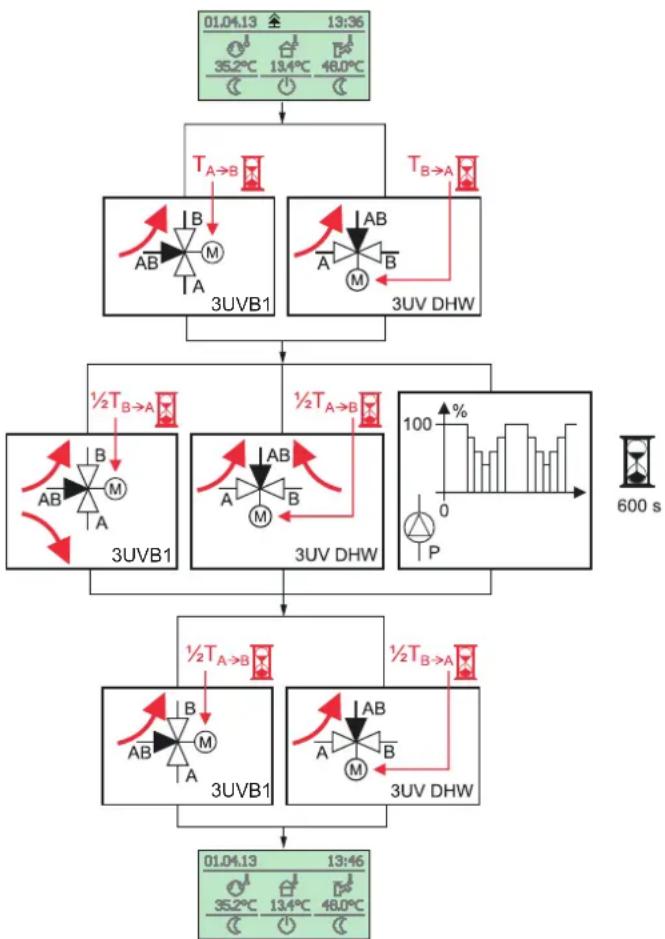
flowchart
graph TD
    A["01.04.13 13:36"] --> B["T_A→B"]
    B --> C["3UVB1"]
    B --> D["3UV DHW"]
    C --> E["½T_B→A"]
    D --> F["½T_A→B"]
    E --> G["3UVB1"]
    F --> H["3UV DHW"]
    G --> I["½T_A→B"]
    H --> J["½T_B→A"]
    I --> K["3UVB1"]
    J --> L["3UV DHW"]
    K --> M["01.04.13 13:46"]
    L --> N["01.04.13 13:46"]
Fig. 3-17 Processes of the Air Purge
- Set the rotary switch to the "Operating Mode" ⏻... Position and set the required operating mode (see chap. 3.4).
Detailed explanations and possible setting values of this function can be found in chap. 6.2.1.
3.6.11 Anti-legionella system

WARNING!
There is a danger of scalding at target hot water temperatures over 60 °C. This is possible when using solar energy if the Legionella protection or Smart Grid functions are activated or the target hot water temperature is set higher than 60 °C.
- Install scald protection in the hot water distribution line (e.g. VTA32 + Screw set 1").
This function is used to prevent bacterial contamination in the hot water storage tank. Refer to the national regulations for the precise drinking water hygiene regulations.

The Legionella protection function is deactivated in the factory in the Daikin Altherma M ECH _2 O, as the risk of contamination is very low due to the following reasons:
– Low volume of the heat exchanger (stainless steel) for heating drinking water.
- Frequent, complete water exchange "first-in-first-out".
- No stagnant water areas in the stored drinking water.
When the Legionella protection function is activated (parameter [Anti-Legionella day]), the connected hot water storage tank is heated up to a disinfection temperature 1x daily or 1x weekly. The anti-legionella system function is active for one hour.

Heating the hot water to the disinfection temperature is carried out irrespective of the target hot water temperatures set by the user or the heating technician.
A connected circulation pump is automatically switched on during thermal disinfection.
The setting of the parameters for the anti-legionella system is carried out in the "Configuration" rotary switch setting at the "DHW Configuration" level.
With the factory settings, the storage tank is recharged at 03:30 hours if the target hot water temperature at this point in time is below 65 °C.
Detailed explanations and possible setting values of this function can be found in chap. 6.2.4.
3.6.12 Resetting to factory settings (reset)
If the Daikin Altherma M ECH _2 O no longer functions correctly and no other cause for the incorrect behaviour can be determined, it may be appropriate to reset all controller settings to the factory settings. There are 3 ways of doing this.
Option 1
With user access rights the switching time programs can be reset to the factory settings in the "Special Level", according to tab. 3-9.
- Push the Exit button for at least 5 s.
→ Menu "Special Level" is displayed. - Use the rotary button to select the "Timeprog Reset" program.
- Execute the program by briefly pressing on the rotary button.
→ The respective values are reset to the factory setting. - Use the rotary button to select "Return".
- Confirm the selection with a brief push of the rotary button.
Option 2
With technician access rights all customer-specific parameter settings can be reset to the factory settings in the "Special Level", according to tab. 6-1 to tab. 6-11.
- Enter the technician code (see chap. 3.6.1).
→ After entering, the "Setup" level is displayed. - Push the Exit button for at least 5 s.
→ Menu "Special Level" is displayed. - Use the rotary button to select the "Reset?" program.
- Execute the program by briefly pressing on the rotary button.
→ The respective values are reset to the factory setting. - Use the rotary button to select "Return".
- Confirm the selection with a brief push of the rotary button.
Option 3
If fundamental changes to the Daikin Altherma M ECH_2O are required for the function within the RoCon system, the basic configuration can be set to the delivery state or redefined with technician access rights.
- Enter the technician code (see chap. 3.6.1).
→ After entering, the "Setup" level is displayed. -
Use the rotary button to select the "System Config" level.
-
Confirm the selection with a brief push of the rotary button.
→ An overview is displayed.
-
Use the rotary button to select the "Delete" program.
-
Confirm the selection with a brief push of the rotary button.
→ The Daikin Altherma M ECH is restarted.
→ The "No Basic Configuration" message is displayed.
- Set the rotary switch to the "Info" ⓘ position.
→ The "Basic Configuration Not Set" message is displayed.
- Now it is possible to either carry out the settings individually (a) or to automatically load the factory settings (b).
a) Press the rotary button briefly.
→ The parameter overview of the "Basic Configuration" level is displayed, and the settings can be carried out manually according to tab. 6-14.
b) Switch the Daikin Altherma M ECH _2 O off and then on again.
→ After restarting the Daikin Altherma M ECP, a prompt asking whether the standard configuration should be used appears. If it is confirmed with "Yes", the default basic configuration is loaded. If "No" is selected, the settings must be carried out manually, see a).
More detailed explanations and possible setting values for this function can be found in chap. 6.12.

After resetting to the factory settings using option 2 or 3, the system must be adjusted to the installation environment again by the heating expert and all customer-specific parameters need to be reset.
3.6.13 Screed program
The screed program is used exclusively for the specified drying of newly created screed for floor heating. Here, the heat generator is operated over several days in accordance with a specified temperature profile (the basis for the preset temperature profile is the recommendation of the surface heating federal association for screed curing heating).
After entering the technician code, temperatures and the duration of the screed program can be set freely in the "Configuration" rotary switch position in the "HC Configuration" level in the parameter [Screed Program].
The screed program is a special function and is not interrupted by any other operating mode. It can only be activated by the heating expert for the direct heating circuit and/or optionally connected mixed heating circuits. It must be activated separately for every heating circuit.

Before starting the screed program, the parameters [Interlink fct] and [Room thermostat] must be deactivated.
During a short-term power failure, a previously activated screed function is continued at the point of the interruption.
After activation of the screed program (parameter [Screed] = On), all weather-dependent control functions of the respective heating circuit are switched off. The respective heating circuit works, as a constant temperature control regardless of the operating mode (switching times).
An already started screed program can be deactivated at any time. After ending the screed program, the parameter is automatically set to "Off", and the heating circuit continues to operate according to the currently set operating mode.
Function heating
The function heating serves as proof of the production of defect free work for the heating engineer. A prefabricated heating protocol related to Daikin floor heating can be found in the Internet portal of Daikin.
In this sense, the function heating (identical with "Heating" in EN 1264, section 5.2) is not considered as a heating process to achieve workability of the screed. Generally, a special screed curing heating and/or mechanical drying is required for this.
The heating of cement screeds should be carried out at the earliest after 21 days and of anhydrite screeds after 7 days at the earliest in accordance with the specifications of the manufacturer. The first heating begins with a T-HS of 25 °C that must be maintained for 3 days. Afterwards, the heating is carried out with the maximum set T-HS for the heating circuit (limited to max. 55 °C), which must be maintained for a further 4 days.
After the described heating process, it is not yet assured that the screed has reached the required moisture content for workability of the screed.
The moisture content in the screed must be checked by measurement prior to laying the surface covering.

Procedure in accordance with EN 1264 Part 4:
1 For anhydrite and cement screeds, the heating circuits must be leak tested by a water pressure test after completion. The leaktightness must be ensured immediately before and during the laying of the screed. The height of the test pressure is at least 1.3x the maximum permitted operating pressure.
Suitable measures must be taken if there is a risk of freezing, e.g. use of antifreeze agents or heating the building. If antifreeze agents are no longer necessary for the intended operation of the system, the antifreeze agent must be removed by draining and rinsing the system with at least 3 changes of the water.

line
| z | t1 | t2 | |---|-----|-----| | 0 | 0 | | | 3.5 | | t2 | | 7.5 | | |t_1 Start temperature 25 °C
t_2 Maximum heating circuit temperature
t_V T-HS
Z Duration of the screed function in days after starting the function
Fig. 3-18 Chronological sequence of the screed program during the function heating
Screed curing heating
The drying process for the screed cannot be exactly predicted. If there is a high degree of humidity, sometimes it can stop completely. The drying process can be speeded up by activating the floor heating (screed curing heating) or measures such as mechanical drying.
Each screed curing heating must be ordered separately by the client as an extra service in accordance with German construction contract procedures (VOB). The workability of the screed is a prerequisite for beginning the work of the top floor installer, so that he can produce defect free work.
3 Operation
With standard settings, the combined function and screed curing heating program can be activated to achieve the required residual moisture in the screed for screed curing (see fig. 3-19). However, the residual moisture of the screed must basically be checked metrologically before the flooring can be laid.

line
| z | t1 | t2 | |---|---|---| | 0 | 0 | 0 | | 1 | 1 | 0 | | 3 | 1 | 0 | | 4 | 1 | 2 | | 5 | 1 | 2 | | 6 | 1 | 2 | | 7 | 1 | 2 | | 8 | 1 | 0 | | 9 | 1 | 1 | | 10 | 1 | 2 | | 19 | 1 | 2 | | 20 | 1 | 2 | | 21 | 1 | 1 | | 22 | 1 | 0 |Fig. 3-19 Chronological sequence of the screed program during the combined function and screed curing heating (for legend, see fig. 3-18)
More detailed explanations and possible setting values for this function can be found in chapters 6.2.3 and 6.13.2.
Setting and starting the screed program
The screed program already includes factory default values which can, however, be individually adjusted.
The day on which the screed program is activated is not counted in the runtime of the program. The 1st day starts at the change of day at 00:00 am. On the day of activation, the setting of the 1st program day is used for heating for the remaining time.
- Enter the technician code (see chap. 3.6.1).
→ After entering, the "Setup" level is displayed. - Use the rotary button to select the parameters [Interlink fct] and [Room thermostat] and check whether they are deactivated (see tab. 6-1).
Both parameters must be set to "Off" before starting the screed program. - Briefly press the Exit button.
→ An overview is displayed. - Use the rotary button to select the "HC Configuration" level.
→ An overview is displayed. - Use the rotary button to select the [Screed Program] parameter.
- Check the settings for the screed program, and set according to the manufacturer specifications for the screed if necessary (see fig. 3-20).
- The adjustment range always lies between 0.0 and 65^ .
- The increment is 1 °C.
| Day | Factory setting | Day | Factory setting |
| 1 - 3 | 25 °C | 10 - 19 | 55 °C |
| 4 - 7 | 55 °C | 20 | 40 °C |
| 8 | 25 °C | 21 | 25 °C |
| 9 | 40 °C | 22 - 26 | - |
Tab. 3-11 Screed program default settings
- Briefly press the Exit button.
→ An overview is displayed. - Use the rotary button to select the [Screed] parameter.
-
Confirm the selection with a brief push of the rotary button.
→ The setting of the parameter is displayed. -
Use the rotary button to set the parameter for the function to "On", and confirm by pressing the rotary button briefly (see fig. 3-20).
→ Screed program starts.
The key lock (if it was activated prior to the start of this function) is reactivated within 2 s to prevent undesired cancellation of the function through operation of the RoCon mb controller.
After the screed program has ended, the RoCon mb control unit continues to work in the previously set operating mode. If not configured beforehand, the following finishing work is necessary.
a) On connection without room station:
- Set the heating characteristic curve or desired target feed temperature.
b) On connection with room station:
• Activate the room station.
- Set the heating characteristic curve or desired target feed temperature. If necessary, activate the parameter [Room Influence] and set the target room temperature.

flowchart
graph TD
    A["Configuration"] --> B["System Configuration"]
    B --> C["HC Configuration"]
    C --> D["DHW Configuration"]
    D --> E["HC Function T-Frost Protect"]
    E --> F["HC Configuration"]
    F --> G["Screed"]
    G --> H["Screed Program"]
    H --> I["Screed Program Day 1 25 °C"]
    I --> J["Day 1"]
    J --> K["Day 1 26 °C"]
    K --> L["Day 1 25 °C"]
    L --> M["Day 1 26 °C"]
    M --> N["70°C"]
    N --> O["70°C"]
    O --> P["70°C"]
    P --> Q["70°C"]
    Q --> R["70°C"]
    R --> S["70°C"]
    S --> T["70°C"]
    T --> U["70°C"]
    U --> V["70°C"]
    V --> W["70°C"]
    W --> X["70°C"]
    X --> Y["70°C"]
    Y --> Z["70°C"]
    Z --> AA["70°C"]
    AA --> AB["70°C"]
    AB --> AC["70°C"]
    AC --> AD["70°C"]
    AD --> AE["70°C"]
    AE --> AF["70°C"]
    AF --> AG["70°C"]
    AG --> AH["70°C"]
    AH --> AI["70°C"]
    AI --> AJ["70°C"]
    AJ --> AK["70°C"]
    AK --> AL["70°C"]
    AL --> AM["70°C"]
    AM --> AN["70°C"]
    AN --> AO["70°C"]
    AO --> AP["70°C"]
    AP --> AQ["70°C"]
    AQ --> AR["70°C"]
    AR --> AS["70°C"]
    AS --> AT["70°C"]
    AT --> AU["70°C"]
    AU --> AV["70°C"]
    AV --> AW["70°C"]
    AW --> AX["70°C"]
    AX --> AY["70°C"]
    AY --> AZ["70°C"]
    AZ --> BA["70°C"]
    BA --> BB["70°C"]
    BB --> BC["70°C"]
    BC --> BD["70°C"]
    BD --> BE["70°C"]
    BE --> BF["70°C"]
    BF --> BG["70°C"]
    BG --> BH["70°C"]
    BH --> BI["70°C"]
    BI --> BJ["70°C"]
    BJ --> BK["70°C"]
    BK --> BL["70°C"]
    BL --> BM["70°C"]
    BM --> BN["70°C"]
    BN --> BO["70°C"]
    BO --> BP["70°C"]
    BP --> BQ["70°C"]
    BQ --> BR["70°C"]
    BR --> BS["70°C"]
    BS --> BT["70°C"]
    BT --> BU["70°C"]
    BU --> BV["70°C"]
    BV --> BW["70°C"]
Fig. 3-20 Setting the screed program
3.6.14 Relay test
In the event of error messages, heating problems or as part of annual maintenance, it may be necessary to check the function of the internal switching relays.
- Enter the technician code (see chap. 3.6.1).
→ After entering, the "Setup" level is displayed. - Briefly press the Exit button.
→ The "Configuration" level is displayed. - Use the rotary button to select the "System Configuration" level.
- Confirm the selection with a brief push of the rotary button.
→ An overview is displayed. - Use the rotary button to select the parameter [Relay Test]:
→ All relays are deactivated.
→ A selection list of all relays is displayed (for the assignment of the relays, see chap. 6.2.2). - Use the rotary button to select the relays to be checked.
- Confirm the selection with a brief push of the rotary button.
→ A relay is activated.
• Cancellation and jump back by:
– briefly pressing the Exit key or the rotary button
– selecting another menu using the rotary switch.
Detailed explanations and possible setting values of this function can be found in chap. 6.2.2.
3.6.15 Settings for optional circulation pump
For greater convenience in draining the water, an optional circulation pump can be switched with the RoCon mb control unit.
There are 2 setting options for this:
a) Separate switching time program (see chap. 3.4.7). Here, the circulation pump works according to an independent switching time program.
b) Together with a hot water switching time program. Here, the circulation pump is controlled in parallel to the operating times of a hot water switching time program.
Independent of the set switching time program, the energy consumption of the circulation pump can be minimised by operating it in pulse mode. The [Circl-Pump Interval] parameter sets the duration of operation of the circulation pump within a 15-minute interval.
Defining the switching time program for the circulation pump
- Set the rotary switch to the "Configuration" position.
→ An overview is displayed. - Use the rotary button to select the "DHW Configuration" level.
- Confirm the selection with a brief push of the rotary button.
→ An overview is displayed. - Select the parameter to be set with the rotary button.
- [Circl-Pump DHW]: Setting of whether the circulation pump is actuated by the active hot water switching time program [ON] or by the separate switching time program [OFF].
– [Circl-Pump Interval]: Setting of the interval control for optional circulation pump. - Confirm the selection with a brief push of the rotary button.
- Set the parameter.
- Confirm the selection with a brief push of the rotary button.
→ The circulation pump is controlled by the RoCon mb control unit in accordance with the entered settings.
Possible setting values of this rotary switch setting can be found in chap. 6.2.4.
3.6.16 Remote control via Internet
An optional gateway (EHS157056) can be used to connect the RoS controller to the Internet. This enables remote control of MtheCBAikin Altherma _2 O by mobile phones (by app).
Operation is possible intuitively.
4 Initial start-up
i
In addition to the commissioning instructions listed in this chapter, the specific commissioning instructions listed in the respective installation instructions for the Daikin Altherma M ECH₂O must be observed.
The RoCon system offers a very wide range of application and extension options.
The individual RoCon system components communicate via the CAN data bus. For this reason, the RoCon BM1 printed circuit boards and the RoCon B1 control panels of the Daikin Altherma M ECH₂O, as well as any optional EHS157034 room station and EHS157068 mixer module system components are connected to each other via data bus lines.
These system components must be allocated unique functional IDs, so that the data exchange and the assignment within the RoCon system functions without any problems.
In many applications, nothing needs to be changed in the basic settings. The more RoCon system components that are integrated in the RoCon system, the more adjustments that need to be made during initial commissioning or when extending the heating system.
The assignment of the functional IDs is easiest when carried out via the "Setup Wizard" installation menu. Most IDs can also be adapted subsequently to the conditions by means of individual parameter settings in the specific parameter levels (see Chapter 6).
a) If no optional RoCon system components are connected to the Daikin Altherma M ECH₂O, communication in the RoCon system is limited to just the RoCon BM1 printed circuit board and the integrated RoCon B1 control panel.
→ Adaptation of the IDs is not necessary.
→ The question displayed during initial commissioning "Use Standard Config" can be confirmed by "Yes".
b) If optional RoCon system components such as EHS157034 and / or EHS157068 are connected, adaptation of the IDs may be necessary.
4.1 Fundamental aspects of the IDs and authorisations in the RoCon system
In the RoCon system, the following functional IDs that are relevant for data exchange of the RoCon system components exist:
| ID / Function | System components | Parameters | Comments |
| Heating circuit IDUnique numbering of a heating circuit in the heating system in the RoCon system. A maximum of 16 heating circuits can be controlled. | Daikin Altherma M ECH2O (RoCon BM1) | [Unmixed Circ Config] See tab. 6-14 | Factory setting = 0Should not normally be changed.1) |
| EHS157034 room station | [HC Assignment] See tab. 6-1 | Factory setting = OffAdaptation required if there are different heating circuits in the system and / or the parameter [Master-RoCon] = On | |
| EHS157068 mixer module | [HC Assignment] See tab. 6-15 | Factory setting = OffMust always be adapted to the setting of the address switch (fig. 4-2). | |
| Heat generator IDUnique numbering of a heat generator in the RoCon system.1) | Daikin Altherma M ECH2O (RoCon BM1) | [BUS ID HS] See tab. 6-14 | Factory setting = 0Should not normally be changed.1) |
| EHS157068 mixer module | [Boiler Assignment] See tab. 6-15 | Factory setting = 0Should not normally be changed.1)Defines the heat generator that supplies the assigned heating circuit with heat. | |
| Terminal IDUnique numbering of a RoCon B1 or EHS157034 control unit from which a heat generator and/or mixer module can be remote controlled in the RoCon system.The authorisation for remote control can be allocated to up to 10 control units in the RoCon system. If remote control in the RoCon system is to be possible, the control unit must be allocated the ID "0". | Daikin Altherma M ECH2O (RoCon BM1) | [Terminaladress] See tab. 6-1 | Factory setting = OffThe value should be set to "0" if at least 1 mixer module is connected in the RoCon system, and the mixer circuit is to be operated from the heat generator. |
| EHS157034 room station | [Terminaladress] See tab. 6-1 or tab. 6-15 - depending on the set heating circuit ID and the current operating mode | Factory setting = OffThe value must be set to a unique numerical value in the RoCon system if the room station system components are to be remotely controlled using a valid device ID. | |
| Device IDUnique numbering of a heat generator or mixer module in the RoCon system.Up to 16 device numbers can be allocated.These device numbers are detected during a [Bus - Scan] and are displayed for identification of a remotely controlled device. | Daikin Altherma M ECH_2O (RoCon BM1) | [BUS ID HS] See tab. 6-14 | Identical to heat generator detection.The value must not be the same as the heating circuit ID of a mixer module in the RoCon system. |
| EHS157068 mixer module | [HC Assignment] See tab. 6-15 | Identical to the heating circuit ID.The value must not be the same as the heat generator ID of a Daikin Altherma M ECH_2O in the RoCon system.The value must be the same as the setting of the address switch (fig. 4-2). |
Tab. 4-1 Functional IDs in the RoCon system
1) A maximum of 8 heat generators can be connected in the RoCon system via the CAN data bus. Several heat generators integrated in the heating installation must be regarded as a special application. If necessary contact a Daikin service technician.
If several control units are incorporated in the RoCon system of a heating installation, additional parameter settings are relevant for this and can be used to set the individual functions and parameters using the appropriate authorisations.
For the EHS157034 room station
– [RoCon U1 assign] parameter:
- The setting = "Living Room" can be used to influence the heating circuit defined by the set heating circuit ID.
- The setting = "Mixing Valve" can be used to carry out all the settings for the mixer circuit defined by the set heating circuit ID.
– [Master-RoCon] parameter:
If the heating circuit ID is set for the direct heating circuit of a Daikin Altherma M ECH₂O, the setting = "On" can be used to activate the master RoCon function. In addition to the heating circuit functions, the hot water functions of the Daikin Altherma M ECH₂O can also be operated with this room station.
Activation of the master RoCon function can also be used for heating systems that consist only of a DaikinAltherma M ECH _2 O (without heating circuit extension) and a room station, and which are to be operated primarily via the room station (observe following information).

If the master RoCon function is activated, the operating mode of the heat generator is set via the room station, and this is shown on the display.
The settings on the room station are transferred to the heat generator, but not vice versa. The room station has priority.
If the [Summer] operating mode is set, for example, and subsequently, on the Daikin Altherma M ECH₂O control panel, the [Heating] operating mode is set, no heating circuit requirement is generated, because the direct heating circuit assigned to the room station via the heating circuit ID is still in [Summer] operating mode. The change in operating mode must therefore be carried out at the room station.
On heating systems with heating circuit extensions, we recommend not activating the master RoCon function (setting = "Off") and instead using the terminal function.
For all RoCon B1 and EHS157034 control units
– [Terminaladress] parameter:
As soon as a control panel has been assigned with a terminal ID (all settings except "Off"), the control panel can be used to activate the terminal function.
After carrying out the [Bus - Scan], all the system components integrated in the RoCon system can be remotely controlled using a valid device ID (caretaker authorisation).
If the terminal function is to be used in the heating system, the terminal ID = 0 must be allocated to a control unit.
4.2 Operating Support during 1st.
Commissioning and during System Extensions
When a Daikin Altherma M ECH _2 O or a EHS157034 room station is switched on for the first time, setting the user language is normally offered first.
Then, on the Daikin Altherma M ECH₂O you will be asked "Use Standard Config?". This query can normally be answered with "Yes".
Only in special applications (e.g. several heat generators in the RoCon system) should the answer be "No". In this case, the "Basic Configuration" parameter level will be offered in order to set the necessary adaptations (see tab. 6-14).
In the case of the EHS157034 room station, after setting the user language, the "Setup Wizard" installation menu appears.

Fig. 4-1 "Setup Wizard" display
The items for defining the function, the authorisation and the IDs of the room station in the RoCon system are requested and checked for plausibility.
This prevents duplicate device and terminal IDs being set.
Therefore, it is recommended that you use this installation menu when extending or making changes to the RoCon system of the heating installation. To do this, a room station already integrated in the heating installation must first be reset.
- Enter the technician code (see chap. 3.6.1).
- Push the Exit button for at least 5 s.
→ Menu "Special Level" is displayed. - Use the rotary button to select the "RoCon B1/U1 Reset" program.
- Execute the program by briefly pressing on the rotary button.
→ The "Setup Wizard" installation menu starts.
4.3 Commissioning Daikin Altherma M ECH _2 O
The prerequisite for initial commissioning is the completion of all preparatory installation work as per the installation and maintenance instructions for the. DaikinAltherma M ECHO
- Switch on the power supply to the Daikin Altherma M ECH _2 O.
→ After the start phase, the operating language selection is displayed. - Use the rotary button to select the desired language.

The operating language can be changed again at any time.
- Confirm the selection with a brief push of the rotary button.
→ The "Use Standard Config?" message is displayed. - Confirm the default "Yes" by briefly pressing on the rotary button (see also chap. 4.2).
→ The Basic Configuration of the RoCon device is loaded.
→ The "Starting Up" message is displayed.
→ The "Initialization" message is displayed.
→ The standard display for the current rotary switch setting is shown. - Adjust settings related to the configuration of the heating system on the RoCon device (see chap. 3.6).
4.3.1 Assigning the terminal ID on the RoCon B1 control panel of the Daikin Altherma M ECH₂O

If several control units are connected in the RoCon system via the data bus, it is important to note that the [Terminaladress] parameter = 0 must be set for a heat generator.
Make sure not to assign a duplicate value as the setting of the [Terminaladress] in the RoCon system.
- Enter the technician code (see chap. 3.6.1).
→ After entering, the "Setup" level is displayed. - Use the rotary button to select the [Terminaladress] parameter.
- Confirm the selection with a brief push of the rotary button.
- Within the display, use the rotary button to set the unique terminal address.
For reasons of clarity, this control unit must be assigned the value = 0. - Confirm the selection with a brief push of the rotary button.
→ Change has been accepted. Jump back to previous display.
Detailed explanations and possible setting values for this rotary switch setting can be found in chap. 6.2.1.
4.4 Putting optional RoCon system components into operation
4.4.1 M1 Mixer module EHS157068
The EHS157068 mixer module has no separate control unit. For configuration and operation, it must be connected via a CAN bus line to a RoCon controller installed in the heat generator or a EHS157034 room station.

In conjunction with a room station, the mixer module can also be operated as a free-standing heating circuit controller.
To operate the mixer module directly via the RoCon B1 control panel of the Daikin Altherma M ECH _2 O, it must be assigned with a terminal ID, and the terminal function must be activated (see chap. 3.4.9).
After selection and confirming an external device, the terminal function for this device is activated and the associated standard display for this device is shown in the display.
The operating component is then in terminal operation.
In the rotary switch position 📄, the local control panel acts as a remote control for the external device. In this case, all the control functions are performed and saved 1:1 as on the external device.
For reasons of clarity, this control unit must be assigned the value = 0.

If, in the rotary switch position 📄, the message "n.A." is displayed, no valid terminal ID has been assigned to this RoCon B1 control panel yet.
If the "n.A." message is still displayed, it may be necessary to update the device software in order to use the terminal function. Contact the Daikin Service Team for this.
A unique device ID ( ≥ 1 ) must be set on the address switch (see fig. 4-2) for the heating circuit to be controlled by this mixer module, which must be synchronised with the [HC Assignment] parameter of the mixer module (see tab. 4-1]).
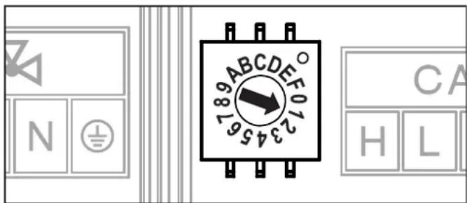
Fig. 4-2 Setting the device ID for the EHS157068 mixer module
All settings and operating steps for this heating circuit are performed in the same way as those for the direct heating circuit. The overview of the available parameters and their settings can be found in chap. 6.13.
The current operating status can be determined directly on the EHS157068 mixer module (see fig. 4-3).

1 LED red - Flashing: Internal error
(error code is communicated to the relevant control unit over the CAN bus)
- To: Undervoltage of the internal clock after a power failure (>10 h)
2 LED green - To: Display during operation, mixer module switched on
3 LED green - To: CAN communication established
4 LED green - To: Mixer circuit pump switched on
5 LED green - To: Mix valve "OPEN" is activated
6 LED green - To: Mix valve "CLOSED" is activated
Fig. 4-3 Explanation of symbols for EHS157068 status displays
4.4.2 EHS157034 room station
The EHS157034 room station can be used as
a) a remote control unit for the DaikinAltherma M ECH 2 O,
b) a mixer circuit operating unit (as a mixer circuit extension or as a freestanding mixer circuit controller),
c) a room thermostat for the Daikin Altherma 2 O,
d) remotely controlled unit for the entire RoCon system (with terminal function activated).
The room station must be connected using a CAN bus line to the Daikin Altherma M ECH₂O's installed RoCon controller or a EHS157068 mixer module. No separate mains supply is necessary for the room station.
Sequence for initial commissioning (see also c#.2).
- Set the rotary switch on the EHS157034 room station to the "Info" ⓘ position.
- Switch on the power supply to the respective Daikin Altherma M ECH₂O.
→ After the start phase, the operating language selector is displayed on the EHS157034 room station.
- Use the rotary button to select the desired language.

The operating language can be changed again at any time.
- Confirm the selection with a brief push of the rotary button.
→ The "Setup Wizard" message is displayed. -
Use the rotary button to set the desired operating function for the room station.
-
"Living Room": Operating function, see a), c), d)
- "Mixing Valve": Operating function, see b)
→ Depending on the selected application, the further configuration is based either on A or B in the following sections.

All operating steps after initial commissioning for the assigned heating circuit are carried out similarly to those on the RoCon B1control panel of the Daikin Altherma M ECH₂O.
However, not all functions (e.g. manual operation, resetting faults) of the Daikin Altherma M ECH₂O can be activated with the room station.
A: Configuration for the "Living Room" setting
- Confirm the "Living Room" setting by briefly pressing the rotary button.
Setting of the heating circuit ID ([HC Assignment] parameter) is displayed. - Use the rotary button to select the associated heating circuit in the [HC Assignment] parameter.
- Confirm the selection with a brief push of the rotary button.
Setting of the terminal ID ([Terminaladress] parameter) is displayed. - Use the rotary button to set the [Terminaladress] parameter.
- Confirm the selection with a brief push of the rotary button.
→ The standard display is shown (see fig. 4-4).

1 Date
4 Current outside temperature
2 Time
5 Operating mode active for
3 Current room temperature
the assigned heating circuit
Fig. 4-4 Standard EHS157068 - "Living Room" display
→ The settings on the EHS157034 room station are only valid for the assigned heating circuit (except if the terminal function is active).
B: Configuration for "Mixing Valve" setting
- Confirm the "Mixing Valve" setting by briefly pressing the rotary button.
→ Setting of the heating circuit ID ([HC Assignment] parameter) is displayed. - Use the rotary button to set the [HC Assignment] parameter. This parameter must be identical to the setting of the address switch in the mixer module (see fig. 4-2), that is allocated to the EHS157034 room station.
- Confirm the selection with a brief push of the rotary button.
Setting of the terminal ID ([Terminaladress] parameter) is displayed. - Use the rotary button to set the [Terminaladress] parameter.
→ The standard display is shown (see fig. 4-4).
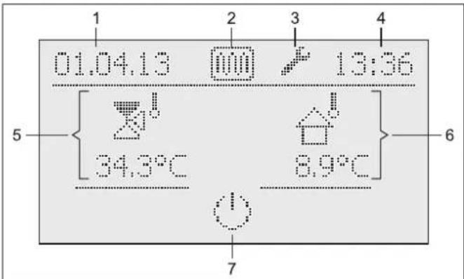
1 Display date
5 Current T-HS of the mixer circuit
2 Status display: Screed function active
6 Current outside temperature
3 Status display: Expert login
7 Operating mode setting for the assigned heating circuit
4 Display time
Fig. 4-5 EHS157068 standard display - "Mixing Valve" with example status displays

In the "Mixing Valve" setting, the room sensor of the EHS157068 is deactivated.
4.4.3 Allocating the EHS157068 mixing module to a heat generator
If just 1 heat generator is integrated in the RoCon system, adaptation of the heat generator ID is not necessary (see tab. 4-1).
If adaptations have to be undertaken, the value of the parameter [Boiler Assignment] (see chapter 6, tab. 6-15) must be set to the same value as the heat generator ID of the Daikin Altherma M ECH₂O that is intended to supply the mixer circuit of this mixer module.
4.4.4 Master RoCon function
Each EHS157034 room station whose heating circuit ID is set to a direct heating circuit can be assigned to the master RoCon function.
- Enter the technician code (see chap. 3.6.1).
→ After entering, the "Setup" level is displayed. - Use the rotary button to select the [Master-RoCon] parameter.
- Confirm the selection with a brief push of the rotary button.
→ The setting of the parameter is displayed. - Use the rotary button to set the parameter for the function to "On", and confirm by pressing the rotary button briefly.
All settings on the EHS157034 room station act in the same way as settings on the RoCon B1 control unit of the assigned heat generator.
As a result, the functions for hot water generation can also be remotely operated from the room station.
As the RoCon B1 control panel has control of the assigned heating circuit in this setting, settings undertaken on the Daikin Altherma M ECH₂O control panel only affect the heat generator, not the heating circuit (see chap. 4.1).
4.4.5 Caretaker function
The caretaker function equates to the terminal function (see chap. 3.4.9 and chap. 4.1 under the [Terminaladress] parameter).
5 Parameter overview
5.1 For first commissioning or resetting to factory settings

The parameters listed in this section can only be accessed when the Daikin Altherma M ECH₂O is commissioned for the first time or has been completely reset.
During initial commissioning: After resetting to factory settings:
- Rotary switch setting: Info Ⓧ Resetting to factory settings.
- Switch on the power supply to the Daikin Altherma M ECH₂O.
(see chap. 3.6.12 - Option 3) • Rotary switch setting: Info ⓘ

flowchart
graph TD
    A["Language"] --> B["Use Standard Config"]
    B --> C{Yes No}
    B --> D{Basic Configuration Boiler Function}
    C --> E["01.04.13 13:36"]
    C --> F["35.2°C 13.4°C 48.0°C"]
    D --> G["Unmixed Circ Config"]
    D --> H["BUS ID HS"]
    D --> I["Time Master"]
    D --> J["System Config"]
Tab. 5-1 "Basic Configuration" parameters

After each system restart, the "Configuration" level cannot be accessed for approx. 3 minutes.
5.2 After first commissioning/After successful basic configuration
5.2.1 Rotary switch setting: Configuration

flowchart
graph TD
    A["Setup LCD Brightness"] --> B["HC Configuration"]
    B --> C["DHW Configuration"]
    A --> D["System Configuration Power DHW"]
    D --> E["BUH s1 power Language"]
    D --> F["BUH s2 power Date"]
    D --> G["Power BIV Time"]
    D --> H["TDiff-DHW CH Support Keylock Function"]
    D --> I["T vbh1 max Access Rights"]
    D --> J["Equilibrium Temp RoCon U1 assign"]
    D --> K["Function BSC Master-RoCon"]
    D --> L["Quite Mode Outdoor type"]
    D --> M["Quiet level INDOOR UNIT"]
    D --> N["AUX Fct Glycol"]
    D --> O["AUX time HP Version"]
    D --> P["T-DHW 1 min Function Heating Rod"]
    P --> Q["Delta-T CH"]
    P --> R["V var"]
    P --> S["T-Flow CH adj"]
    P --> T["T-Flow Cooling adj"]
    P --> U["Min Pressure"]
    P --> V["Max Pressure HT/NT Function"]
    P --> W["Set Point Pressure"]
    P --> X["Max Pressuredrop"]
    P --> Y["Relay Test"]

    B --> Z["HC Function"]
    Z --> AA["T-Frost Protect"]
    Z --> AB["Insulation"]
    Z --> AC["Screed"]
    Z --> AD["Screed Program"]
    Z --> AE["Heating"]
    Z --> AF["Cooling ⚙️"]

    A --> AG["System Config"]
    AG --> AH["PWM Config"]

    AH --> AI["Pump dT heating"]
    AH --> AJ["Pump dT cooling"]
    AH --> AK["Pump limit"]

    B --> AL["Sensor Config"]
    AL --> AM["Tamb Config"]
    AL --> AN["Storage Config"]
    AL --> AO["Pressure Config"]

    B --> AP["Start T-Out Cooling"]
    AP --> AQ["T-Outside lim day"]
    AP --> AR["T-Outside lim night"]

    B --> AS["Max T-Out Cooling"]
    AS --> AT["Heat-Slope"]

    B --> AU["T-Flow Cooling start"]
    AU --> AV["TV overshoot"]

    B --> AW["T-Flow Cooling max"]
    AW --> AX["Room Influence"]

    B --> AY["Min T-Flow Cooling"]
    AY --> AZ["T-Room Adj"]

    B --> BA["T-Flow Cooling"]
    BA --> BB["T-Flow Day"]

    B --> BC["T_H/C Switch"]
    BC --> BD["T-Flow Night"]

    B --> BE["Cooling Setpoint adj"]

    B --> BF["Min T-Flow"]

    B --> BG["HC Adaption"]
Tab. 5-2 Parameters in the "Configuration" rotary switch setting
5 Parameter overview
5.2.2 Rotary switch setting: DHW Install


Tab. 5-3 Parameters in the "DHW Install" rotary switch setting
5.2.3 Rotary switch setting: Operating Mode


flowchart
graph TD
    A["Standby"] --> B["Reducing"]
    B --> C["Heating"]
    C --> D["Cooling"]
    D --> E["Summer"]
    E --> F["Automatic 1"]
    F --> G["Automatic 2"]
Tab. 5-4 Parameters in the "Operating Mode" rotary switch setting
5.2.4 Rotary switch setting: Set Temp Day

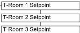
Tab. 5-5 Parameters in the "Set Temp Day" rotary switch setting
5.2.5 Rotary switch setting: Set Temp Night


Tab. 5-6 Parameters in the "Set Temp Night" rotary switch setting
5.2.6 Rotary switch setting: DHW Set Temp


Tab. 5-7 Parameters in the "DHW Set Temp" rotary switch setting
5.2.7 Rotary switch setting: Time Program


flowchart
graph TD
    A["Party"] --> B["Away HC Program 2"]
    B --> C["Vacation DHW Program 1"]
    C --> D["Holiday DHW Program 2"]
    D --> E["HC Program 1 Circulation Time"]
Tab. 5-8 Parameters in the "Time Program" rotary switch setting
5.2.8 Rotary switch setting: Remote Param


Tab. 5-9 Parameters in the "Remote Param" rotary switch setting
5.2.9 Rotary switch setting: Info ⓘ

flowchart
graph TD
    A["Overview Mode: Pump"] --> B["Water Pressure"]
    B --> C["T-HS TV: Tdhw"]
    C --> D["T-HS Setpoint"]
    D --> E["T-Outside"]
    E --> F["T-DHW"]
    F --> G["T-DHW Setpoint"]
    G --> H["T-Return"]
    H --> I["Flow Rate"]
    I --> J["T-HC"]
    J --> K["T-HC Setpoint"]
    K --> L["Status HS pump"]
    L --> M["Runtime Compressor"]
    M --> N["Runtime Pump"]
    N --> O["Mixer Position"]
    O --> P["Qboh Sw Nr Controller"]
    P --> Q["Qchhp"]

    R["Ext: V"] --> S["RT: EHS"] --> T["TVBH: TA"] --> U["TR: Psyst"] --> V["BPV: Tliq2"] --> W["3UVD: quiet"] --> X["TA2: Glycol"] --> Y["(see also chap. 3, fig. 3-5)"]

    Z["Qsc"] --> AA["Qch"] --> AB["QWP"] --> AC["Qdhw"] --> AD["HS type"] --> AE["Sw Nr B1/U1"] --> AF["..."]
Tab. 5-10 Parameters in the "Info" rotary switch setting
5.2.10 Exit key: Special function

flowchart
graph TD
    A["Manual Operation"] --> B["FA failure"]
    B --> C["Protocol"]
    C --> D["Delete message"]
    D --> E["RoCon B1/U1 Reset"]
    E --> F["Parameter Reset"]
    F --> G["Timeprog Reset"]
    G --> H["Return"]
Tab. 5-11 Parameters in "Special Level" level
5.3 M1 Parameter levels for the EHS157068 mixer module
5.3.1 Rotary switch setting: Info ①
See chap. 5.2.9.
5.3.2 Rotary switch setting: Operating Mode

See chap. 5.2.3.
5.3.3 Rotary switch setting: Set Temp Day
See chap. 5.2.4.
5.3.4 Rotary switch setting: Set Temp Night
See chap. 5.2.5.
5.3.5 Rotary switch setting: DHW Set Temp

No function.
5.3.6 Rotary switch setting: DHW Install

No function.
5.3.7 Rotary switch setting: Time Program ☑
See chap. 5.2.7.
5.3.8 Rotary switch setting: Remote Param
See chap. 5.2.8.

5.3.9 Rotary switch setting: Configuration
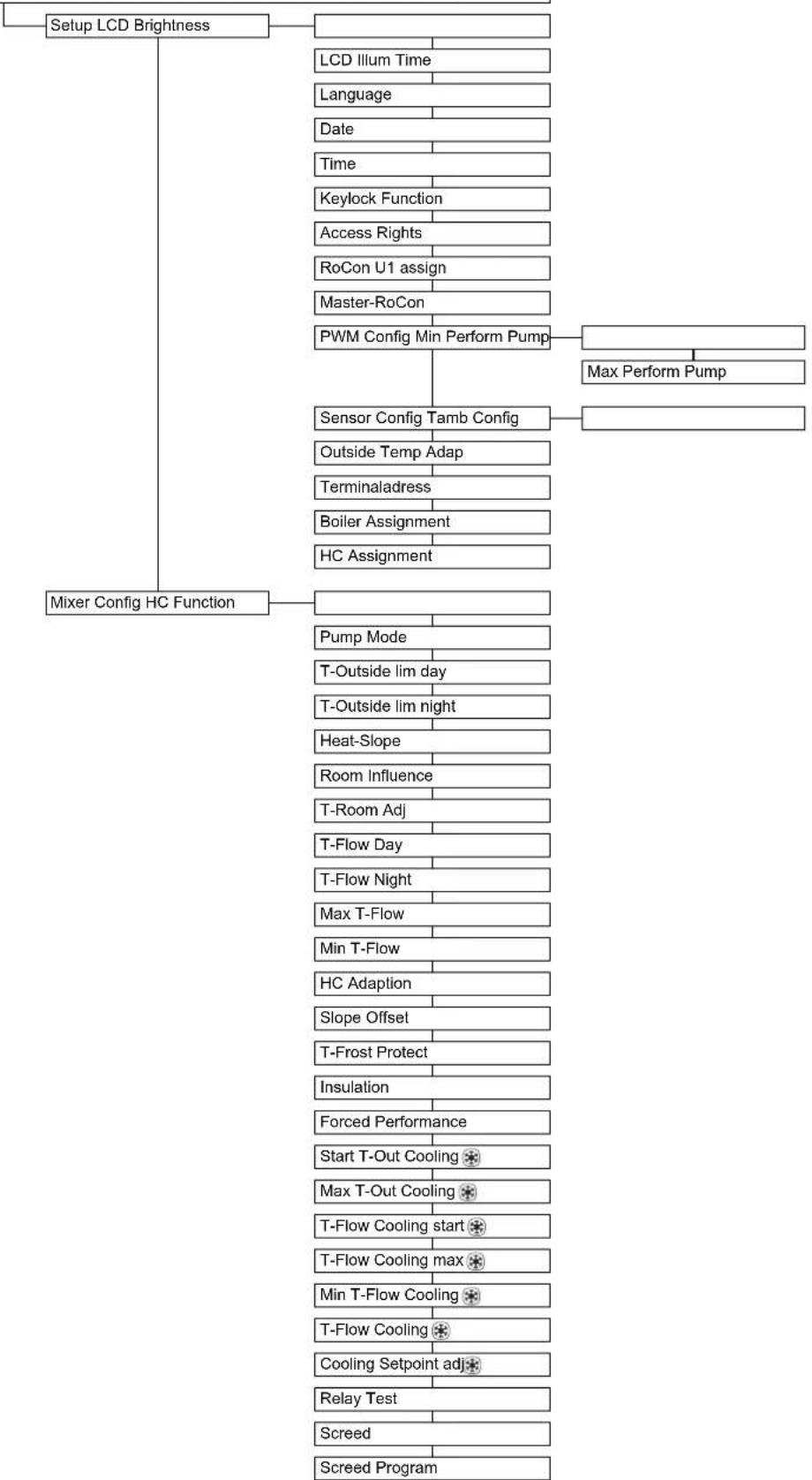
flowchart
graph TD
    A["Setup LCD Brightness"] --> B["LCD Illum Time"]
    B --> C["Language"]
    C --> D["Date"]
    D --> E["Time"]
    E --> F["Keylock Function"]
    F --> G["Access Rights"]
    G --> H["RoCon U1 assign"]
    H --> I["Master-RoCon"]
    I --> J["PWM Config Min Perform Pump"]
    J --> K["Max Perform Pump"]
    A --> L["Mixer Config HC Function"]
    L --> M["Pump Mode"]
    M --> N["T-Outside lim day"]
    N --> O["T-Outside lim night"]
    O --> P["Heat-Slope"]
    P --> Q["Room Influence"]
    Q --> R["T-Room Adj"]
    R --> S["T-Flow Day"]
    S --> T["T-Flow Night"]
    T --> U["Max T-Flow"]
    U --> V["Min T-Flow"]
    V --> W["HC Adaption"]
    W --> X["Slope Offset"]
    X --> Y["T-Frost Protect"]
    Y --> Z["Insulation"]
    Z --> AA["Forced Performance"]
    AA --> AB["Start T-Out Cooling ★"]
    AB --> AC["Max T-Out Cooling ★"]
    AC --> AD["T-Flow Cooling start ★"]
    AD --> AE["T-Flow Cooling max ★"]
    AE --> AF["Min T-Flow Cooling ★"]
    AF --> AG["T-Flow Cooling ★"]
    AG --> AH["Cooling Setpoint adj ★"]
    AH --> AI["Relay Test"]
    AI --> AJ["Screed"]
    AJ --> AK["Screed Program"]
Tab. 5-12 Parameters in the "Configuration" rotary switch setting
6 Parameter settings
6.1 Explanation of the parameter tables
The parameter tables listed in Chaps. 6.2 to 6.11 include compact information on all parameters, which is available in the respective rotary switch setting on the control unit (1st menu level, 2nd menu level).
In addition to the parameter designations, the tables contain details of the setting ranges, factory settings, setting options or setting step distances and brief function explanations.
In addition, they provide explanation of the access rights for operation of the control unit. The following abbreviations are used for corresponding labelling:
BE Access right for the operator
HF Access authorisation with technician code
In the event of different information in the BE and HF columns, login as a heating technician must be carried out prior to selecting the parameter level in order to obtain the status entered in the HF column (see chap. 3.6.1).
Status:
N Not visible
E Visible and configurable
S Visible

Changing some parameters requires a restart of the device. This takes a few minutes. No further settings can be made during this time. The restart can be delayed by 5 minutes in response to the prompt "Restart 1. Perform now?" by selecting "later".
Parameters that require a restart are marked with (*) in the following tables.
6.2 Rotary switch setting: Configuration

6.2.1 "Setup" level
| Sub-level | Parameters Description Access Setting range | Min / Max | Factory setting | Increment | |||
| BE | HF | ||||||
| LCD Brightness | Brightness of the display | E | E | 0 - 100 % | 50 % | 10 % | |
| LCD Illum Time | Lighting duration of the display | E | E | 5 - 120 s | 30 s | 1 s | |
| Language | National language of the display texts on the control unit | E | E | German English French Dutch Italian Spanish Portuguese | German | - | |
| Date | Current date in day/month/year format. The current day of the week is calculated automatically from the date. | E | E | ||||
| Time | Time in hours/minutes format. | E | E | ||||
| Keylock Function | Release of the key lock function:Off: Key lock cannot be activated.On: Key lock can be activated with the rotary button (see chap. 3.3). | E | E | OffOn | Off | - | |
| Access Rights | Access code entry. Setting digit-by-digit like a combination lock (see chap. 3.6.1). | E | E | 0 - 9 | 0000 | 1 | |
| RoCon U1 assign Display only on connected room station:Function of the EHS157034 room station in the CAN data bus system:Living Room: Control unit for the heating circuit allocated in the [HC Assignment] parameter.Mixing Valve: Mixer circuit operating unit (as mixer circuit extension or as a free-standing mixer circuit control unit)In addition to the above functions, the room station can basically be used as a remote control unit for the Daikin Altherma M ECH2O and the entire RoCon system (with activated terminal function) (see chapters 4.1 and 4.4.2). | N | E | Living Room, Mixing Valve | Living Room | - | ||
| Master-RoCon Display only on connected room station:Setting of the master RoCon functionOff: DeactivatedOn: Function activeFor every EHS157034 room station whose heating circuit ID is set on a direct heating circuit, the master RoCon function can be activated (see chap. 4.4.4). Several room stations with active master RoCon function in the system are possible, but only one room station which is assigned to the same heat generator.All settings on the EHS157034 room station work for activated master RoCon function as settings on the RoCon B1 control unit of the assigned heat generator. As a result, the functions for hot water generation can also be remotely operated from the room station. | N | E | OffOn | Off | - | ||
| Outdoor type | Heat pump outdoor unit type0: no selection1: 5 kW2: 7 kW | N | E | 0 - 6 | 0 | 1 | |
| Sub-level | Parameters | Description | Access | Setting range Min / Max | Factory setting | Incre-ment | |
| BE | HF | ||||||
| INDOOR UNIT Heat | pump interior unit typeAdaptation of the set value important, as the device types have different defrosting log-ics.0: no commissioning carried out so far.1: EKHWMX(B)300C2: EKHWMX(B)500C | NE | 0 - 4 0 1 | ||||
| Glycol (*) Adding glycol | to the water circuit is recommended to guarantee frost protection in the event of a power failure. If glycol has been added to the system, the RoCon controller setting must be adapted accordingly.0: no glycol added1: glycol added | SE | 0 - 1 0 - | ||||
| HP Version Version of the HPSU internal unit5: version 5 | NE | 5 5 - | |||||
| Function Heating Rod | Setting regarding whether an additional heat generator (WEZ) for hot water preparation and heating support is available (see chap. 3.6.7).0: no additional WEZ1: optional backup heater2: alternative WEZ undertakes hot water preparation and heating support3: alternative WEZ 1 undertakes hot water preparation and alternative WEZ takes heating support | NE | 0 - 3 1 1 | 2 under- | |||
| Emergency BUH | If the heat pump fails, the backup heater can be used as emergency heating, and can undertake all heating requirements either automatically or non-automatically.0: no automatic emergency operation1: automatic emergency operation | EE | 0 - 1 0 - | ||||
| HZU | Heating support from hot water storage tank if minimum temperature is exceeded (see chap. 3.6.8 and parameter [TDiff-DHW CH Support]).Off: no heating supportOn: heating support function active | NE | OffOn | On | - | ||
| Equilibrium Func. (*) | The bi-valence function is only relevant to operation of the optional heater booster due to a backup requirement (room heating mode).Off: operation of the backup heater is always possible.On: backup heater is only released if the temperature set in the parameter [Equilibrium Temp] is undershot. | NE | OffOn | On | - | ||
| SMART GRID | Evaluation of the SG signal (see chap. 3.4.12).0: Smart Grid function not active, SG signal is not evaluated.1: depending on utility company signal, the heat pump is shut off (no frost protection func-tion - see chap. 3.6.5) or operated at higher temperatures. | NE | 0 - 1 0 - | ||||
| Mode SG | Only if [SMART GRID] parameter = 1:Used for a possible increase in the target temperature in the case of a Smart Grid switch-on command.0: comfort (target hot water temperature increase by 5 K)1: standard (target feed temperature increase by 2 K and target hot water temperature increase by 5 K)2: eco (target feed temperature increase by 5 K and target hot water temperature increase by 7 K) | NE | 0 - 2 1 1 | ||||
| HT/NT Function | Setting regarding which heat sources are switched off if the peak signal output by the util-ity company (EVU) is received in the case of an off-peak mains connection.0: deactivated (no effect)1: refrigerant compressor is switched off2: refrigerant compressor and backup heater are switched off3: everything is switched off (no frost protection function - see chap. 3.6.5) | NE | 0 - 3 0 1 | ||||
| HT/NT Contact | Definition of whether the HT/NT input is evaluated as a normally closed contact or a nor-mally open contact.0: normally open contact (switching contact closed = peak)1: normally closed contact (switching contact closed = off-peak) | NE | 0 - 1 0 - | ||||
| Room thermostat Co-figuration of a room thermostat with potential-free contacts connected to Daikin Altherma M ECH2O connection J16.- Off: Deactivated- On: (only if parameter [Interlink fct] = Off)Evaluation of the heating [III] and cooling [Switching contacts at plug connection J16 on the RoCon BM1 printed circuit board (only if none of the "Standby", "Reduc-ing", "Summer", "Vacation", "Holiday" or "Screed" operating modes are active):a) Closed heating [III] switching contact: operating mode is switched to "Heating".Priority if both switching contacts are closed.b) Closed cooling [Switching contact: operating mode is switched to "Cooling".c) Open contacts: only frost protection active. | NE | OffOn | Off | - | |||
6 Parameter settings
| Sub-level | Parameters | Description | Access Setting range | Min / Max | Factory setting | Increment | |
| BE | HF | ||||||
| Interlink fct Configuration for systems that are operated with 2 different target feed temperatures (see chap. 3.6.6).One possible application is e.g. the additional integration of an FWXV-ATV3 in a surface heating and cooling system.Prerequisite: 2 room thermostats are connected to Daikin Altherma M ECH2O plug connection J16.- Off: Deactivated-On: evaluation of the heating and cooling switching contacts at plug connection J16 on the RoCon BM1 printed circuit board.Activation of cooling mode only by switching the operating mode to "Cooling" (see chap. 3.4.2).Setting of the parameter [Room thermostat] is no longer evaluated.a) Open switching contacts: only frost protection activeb) "Heating" and "Automatic 1" / "Automatic 2" operating mode active during the switching cycles in day mode.- Closed heating switching contact = IL1:→ The system is regulated to the normal target feed temperature as per the parameter settings in the "HC Configuration" > "Heating" level.- Closed cooling switching contact = IL2:→ The system is regulated to the increased target feed temperature (normal target feed temperature + value of the parameter [T-Flow CH adj]. Priority if both switching contacts are closed!c) "Cooling" operating mode active.- Closed heating switching contact = IL1:→ The system is regulated to the normal target feed temperature as per the parameter settings in the "HC Configuration" > "Cooling" level.- Closed cooling switching contact = IL2:→ The system is regulated to the reduced target feed temperature (normal target feed temperature - value of the parameter [T-Flow Cooling adj]. Priority if both switching contacts are closed! | NE | Off | On | Off - | |||
| MF 1 Config | Configuration of the multi-function output (230 V, J14 connection):0: The output is without function.1: Header pump – The output becomes active as soon as a system heating circuit reports a heat requirement to the heat generator.2: Circulation pump – The output is activated either after the time program of the circulation pump or after the time program of the hot water generation, depending on the parametrisation (see chap. 3.4.7).3: Feeder pump – The output becomes active as soon as a heat requirement is pending for the direct heating circuit of the heat generator. | NE | 0 - 3 | 2 | 1 | ||
| Air Purge | Activation of automatic ventilation of the Daikin Altherma M ECH2O and the connected heating circuit (see chap. 3.6.10).Off: DeactivatedOn: Start of the Air Purge | NE | Off | On | Off - | ||
| PWM Config | |||||||
| Pump dT heating (*) | Heating: required temperature difference between return and feed temperature. If a minimum temperature difference is required for good heat distribution system operation in heating mode. | SE | 3 - 10 | 5 | 1 | ||
| Pump dT cooling (*) | Cooling: required temperature difference between return and feed temperature. If a minimum temperature difference is required for good heat distribution system operation in cooling mode. | SE | 3 - 10 | 5 | 1 | ||
| Pump limit (*) | This parameter defines the maximum pump speed. Under normal conditions, the default setting should NOT be changed. The limitation of the pump speed is skipped if the flow rate is in the range of the minimum flow rate.0: No limit1 - 4: Limitation of the pump speed independent of the operating status. This setting cannot guarantee heating comfort. The maximum water flow rate is reduced depending on the setting as follows: 1: 90 %, 2: 75 %, 3: 65 %, 4: 55 %5 - 8: Limitation of the pump speed if there is no heating or cooling requirement. The maximum water flow rate is reduced depending on the setting as follows: 5: 90 %, 6: 75 %, 7: 65 %, 8: 55 %. | SE | 0 - 8 | 6 | 1 | ||
| Sensor Config | |||||||
| Tamb Config (*) | Configuration of the optional outside temperature sensor.0: no sensor evaluation1: sensor evaluation activated. To determine the target feed temperature, this sensor is evaluated and shown on the standard display. | SE | 0 - 1 | 0 - | |||
| Storage Config | Configuration of the hot water generation:Inactive: No function for hot water generation.Sensor: Function for hot water generation is activated. A storage temperature sensor is evaluated for hot water generation (if no storage temperature sensor is connected, an error message is generated).Thermostat: Function for hot water generation is activated. A thermostatic switch (On / Off) is evaluated for hot water preparation, whereby "open terminals" is evaluated as "no requirement". | NE | Inactive Sensor Thermostat | Sensor | - | ||
| Pressure Config | Configuration of the sensor for detection of the water pressure of the system:Off: No sensor evaluationOn: Sensor evaluation activated (if no pressure sensor is connected, an error message is generated.) | NE | Off | On | On | - | |
| Sub-level | Parameters | Description | Access | Setting range Min / Max | Factory setting | Incre-ment | |
| BE | HF | ||||||
| Outside Temp Adap | Individual adjustment for the measured value of the outside temperature relevant for the control unit. | NE | -5.0 to | +5.0 kW 0.0 K | 0.1 K | ||
| Terminaladress Setting | of the terminal ID of the control unit for system access. The set value must be unique throughout the entire system. Confirmation of this parameter with the rotary button effects new initialisation of the control unit.All settings except for "Off" authorise the user of the control unit to activate the terminal function and thus to operate all RoCon system components with a valid device ID (see chap. 3.4.9 and 4.1). | NE | Off, 0 | -9 Off 1 | |||
| System Config | System configuration of the device, consisting of sensor configuration and data bus configuration. If the prompt regarding use of the standard configuration is answered "Yes" when the device is first started, the basic configuration appropriate to the installed heat generator is automatically activated.Confirmation of this parameter with the rotary button when "Inactive" or "Delete" is set leads to re-initialisation of the controller. An error message follows. The rotary switch must then be set to "Info". Use the rotary button to operate the displayed menu guidance. | NE | Inactive | Active Delete | Active | - | |
| HC Assignment Display only on connected room station:Setting of the heating circuit ID for the room station (see chap. 4.1). This parameter determines which heating circuit should be operated with this value.The direct heating circuit of the Daikin Altherma M ECH_2O is set to heating circuit ID "0" as standard (see chap. 6.12, parameter [Unmixed Circ Config]). | NE | Off, 0 | -15 Off | 1 | |||
Tab. 6-1 Parameters in the "Configuration" rotary switch setting, "Setup" level
6.2.2 "System Configuration" level
| Parameters Description Access Setting range | Min / Max | Factory setting | Increment | |||
| BE HF | ||||||
| Power DHW Heat output of the electric heater booster for hot water preparation N E 1000 - | 40,000 W | 3000 W | 1000 W | |||
| BUH s1 power (*) Heat output of the electric heater booster for heating support stage 1See operating instructions for heating element EKBUxx. | NE | - | - | - | ||
| BUH s2 power (*) Heat output of the electric heater booster for heating support stage 2See operating instructions for heating element EKBUxx. | NE | - | - | - | ||
| Power BIV | Setting limits the heating support output. | NE | 3000 | 40000 W | 15000 W | 1000 W |
| TDiff-DHW CH Support | Only if parameter [HZU] = On.Heating support is activated if T_dhw > T_HZUmin + 4K and T_dhw > [T-HS Setpoint] + 1K .Heating support is deactivated if T_dhw < T_HZUmin or T_dhw < [T-HS Setpoint] . T_HZUmin = currently active target hot water temperature [T-DHW Setpoint] + set parameter value [TDiff-DHW CH Support]. T_dhw = current hot water storage tank temperature [T-HS Setpoint] = currently active target feed temperature (see tab. 6-12 and chap. 3.6.4) | NE | 2 - 15 | 5 | 1 | |
| T vbh1 max Setting limits the target feed temperature (measured against t V, BH) when the heating support function is active. | N | E | 5 - 85 °C | 60 °C | 1 °C | |
| Equilibrium Temp (*) | Setting influences the effect of the potential-free AUX switching contact (toggle switch output A) defined in the parameter [AUX Fct].Only if parameter [Equilibrium Func.] = On:Outside temperature as of which the optional heater booster is activated to support room heating. The bi-valence temperature is relevant to operation of the optional heater booster due to a backup requirement (room heating mode). The temperature of the temperature sensor (info value TA) integrated in the heat pump outdoor unit is used for this. | E | E | -15 to +35 °C | 0 °C | 1 °C |
| Function BSC | Selection of the functionality of switching contact EXT (J8):0: evaluation of the resistance valves (see chap. 3.4.2)1: evaluation as a burner blocking contact. If the switching contact is closed, the external heat generator has priority. | SE | 0 - 1 | 0 | - | |
| Quite Mode | Mode for low-noise operation at reduced output (see chap. 3.4.11).0: deactivated1: activated2: only operated in whisper mode at night from 22:00 to 06:00 hours. | EE | 0 - 2 | 0 | - | |
| Quiet level | On selection of low-noise operation, three noise levels can be set.0: less quiet. The output can decline in colder ambient conditions.1: medium quiet. Reduced output is possible under all conditions.2: quietest. The output is reduced under all conditions. | SE | 0 - 2 | 0 | - | |
| AUX Fct | Setting assigns the switching conditions for the potential-free AUX switching contact (toggle switch output A, see chap. 3.6.9).0: function deactivatedAUX switching contact switches:1: if storage tank temperature (Tdhw) ≥ value of parameter [T-DHW 1 min].2: if a cooling request or heating request is present.3: if a hot water request to the backup heater (EKBUxx) is present or the configured backup heater is requested for heating support.4: if an error is pending.5: if the sensor value (TVBH) is > 60 °C.6: if the outside temperature is < parameter value [Equilibrium Temp].→ Heat pump continues to operate = parallel bi-valence mode.7: if the outside temperature is < parameter value [Equilibrium Temp] + a heating request or a hot water request is present.→ Heat pump does not continue to operate = alternative bi-valence mode.8: if a hot water request is present.9: if the outside temperature is < parameter value [Equilibrium Temp] + heat request "room heating" (not for hot water request). Heat pump no longer operates in room heating mode below the value set in the parameter [Equilibrium Temp] - only in hot water mode.Application: alternative room heating bi-valence mode if the boiler is hydraulically integrated so that it directly heats the unpressurised storage tank water of the Daikin Altherma M ECH2O (connection via solar connections).10: "multi-oil" - if the outside temperature is < parameter value [Equilibrium Temp] + heat request "room heating" (not for hot water request). Heat pump no longer operates in room heating mode below the value set in the parameter [Equilibrium Temp] - only in hot water mode.Application: alternative room heating bi-valence mode if the boiler is hydraulically integrated in the heat pump feed. For this application type, the frost protection function must be deactivated on the Daikin Altherma M ECH2O (parameter [T-Frost Protect] = Off).11: if the heat pump is in "Cooling" operating mode. | NE | 0 - 9 | 0 | 1 | |
| AUX time | AUX switching contact (A) only switches after a delay if the switching condition (see parameter [AUX Fct]) is present for longer than the set time. | N | E | 0 - 600 s | 120 s | 5 s |
| T-DHW 1 min | Storage tank temperature (Tdhw) switching threshold for AUX switching contact (see parameter [AUX Fct]). | N | E | 20 - 85 °C | 50 °C | 1 °C |
| Delta-T CH | Target spread for room heating. The heating circulation pump of the Daikin Altherma M ECH2O regulates the flow rate to achieve the target spread stored in the parameter between the target feed temperature and return temperature ( t_V,BH - t_R1 ). | N | E | 2 - 20 K | 7 K | 1 K |
| Parameters | Description | Access | Setting range Min / Max | Factory setting | Incre-ment | |
| BE | HF | |||||
| V var System's currently required minimum volumetric flow (calculated value, not adjustable) N S INFO VALUE XXX - | ||||||
| T-Flow CH adj Only if parameter [Interlink fct] = On:When the RT switching contact cooling is closed, the target feed temperature is increased by the set value (see tab. 6-1, parameter [Interlink fct]). Request e.g. through FWXV-ATV3. | NE | 0 - 50 | K 5 K | 1 K | ||
| T-Flow Cooling adj | Only if parameter [Interlink fct] = On:When the RT switching contact cooling is closed, the target cooling feed temperature is reduced by the set value (see tab. 6-1, parameter [Interlink fct]). Request e.g. through FWXV-ATV3. | NE | 0 - 50 | K 5 K | 1 K | |
| Min Pressure | Defines the minimum water pressure.Pressure monitor function (only with activated pressure sensor, [Pressure Config]=On, see tab. 6-1): if the measured value falls below the set value, the Daikin Altherma M ECH2O is shut off and an error message is generated. | N | E | 0.1 - 5.0 bar | 0.5 bar | 0.1 bar |
| Max Pressure | Defines the maximum water pressure.Pressure monitoring function (only with activated pressure sensor, [Pressure Config]=On, see tab. 6-1): If the measured value exceeds the set value, a warning message is generated. | N | E | 0.1 - 5.0 bar | 3.0 bar | 0.1 bar |
| Set Point Pressure | Defines the target water pressure.Pressure monitoring function (only with activated pressure sensor, [Pressure Config]=On, see tab. 6-1): If the measured value undercuts the set value by more than the value set in the [Max Pressuredrop] parameter, a warning message is generated. | N | E | 0.1 - 5.0 bar | 0.9 bar | 0.1 bar |
| Max Pressuredrop | Defines the maximum acceptable pressure loss in the heating system.Pressure monitoring function (only with activated pressure sensor, [Pressure Config]=On, see tab. 6-1): If the measured value undercuts the value set in the [Set Point Pressure] parameter by more than the set value, a warning message is generated. | N | E | 0.1 - 5.0 bar | 0.5 bar | 0.1 bar |
| Relay Test | Manual control of individual relays for test purposes. After confirmation of this parameter with the rotary button, the list of relays 1 - 9 is displayed with a checkbox on the display. For selec-tion and confirmation of a relay with the rotary button, a tick is placed in the checkbox and the respective relay is activated. Multiple selection is possible.Relay 1: Output J1 (internal heating circulation pump), output pumpRelay 2: Output J14 (circulation pump), mix valve "open"Relay 3: Contact A on output J2 (3UVB1 switching valve), mix valve "Closed"Relay 4: Contact B on output J2 (3UVB1 switching valve)Relay 5: Output J12, 3UV DHW switching valve, "Closed"Relay 6: Output J12, 3UV DHW switching valve "Open"Relay 7: Connection J3 (potential-free relay: Closer B-B1) - AUXRelay 8: Connection J3 (potential-free relay: Changer A-A1/A-A2) - AUXRelay 9: Output J10 (A1P power supply)Relay A: Output J17 (pin 3) - relay K2 (RTX-EHS) output XBUH1 T2Relay B: Output J17 (pin 2) - relay K1 (RTX-EHS) output XBUH1 T3Relay C: Output J17 (pin 4) - relay K3 (RTX-EHS) output XBUH1 T1 | N | E | ☐/☑ | ☐ | - |
Tab. 6-2 Parameters in the "Configuration" rotary switch setting, "System Configuration" level

Depending on the version, individual information parameters are displayed that are not described in tab. 6-2. For this, see tab. 6-12.
6.2.3 "HC Configuration" level
| Sub-level | Parameters | Description | Access | Setting range Min / Max | Factory setting | Increment | |
| BE | HF | ||||||
| HC Function Setting | defines the type of T-HS control.0: Weather-dependent T-HS control1: regulation to a fixed target feed value, depending on heating, cooling or economy mode | NE | 0 - 1 | 0 | 1 | ||
| T-Frost Protect | Off: No frost protection of the heating circuitOtherwise: If the outside temperature drops below the set value, the system switches to frost protection operation (the pumps are switched on). The function is ended if the outside temperature rises above the set value +1 K. | EE | Off,-15 to +5 °C | 0 °C | 1 °C | ||
| Insulation | Setting the building insulation standard. This influences the averaged outside temperature and the automatic adaptations of the heat slope and the heating times. | EE | OfflowNormalGoodVery Good | low | - | ||
| Screed | Function for screed dryingOff: DeactivatedOn: the target feed temperature is regulated according to the set screed program. The day on which the screed function is activated is not included in the running time of the screed program. The first day starts when the day changes at 00:00 am. On the day of activation, heating is carried out for the remaining time with the target feed temperature of the first day's program (see chap. 3.6.13).If screed drying is started or stopped manually, the parameter [Equilibrium Temp] must be checked and adapted if necessary to ensure that the heating rod is used properly. | NE | OffOn | Off | - | ||
| Screed Program | Setting of the sequence program of the screed heating. A separate target feed temperature can be set for each day for a maximum duration of 28 days. The end of the screed program is defined by the 1st day with the target value setting "----" (see chap. 3.6.13). | N | E | 10 - 70 °C per heating day | See tab. 3-11 | 1 °C | |
6 Parameter settings
| Sub-level | Parameters | Description | Access Setting range | Min / Max | Factory setting | Incre-ment | |
| BE | HF | ||||||
| Heating | |||||||
| T-Outside lim day | Automatic summer shut-off setting for heating mode. If the outside temperature measured and averaged by the controller exceeds the set value by 1 K, the heating circuit is switched off. The heating is released again if the outside temperature undercuts the set heating limit. | E E | Off, 10 | -40 °C 19 °C | 0.5 °C | ||
| T-Outside lim night | Heating limit setting for heating circuit "shut-off" during the reduction time (function as in parameter [T-Outside lim day]). | E E | Off, 10 | -40 °C 10 °C | 0.5 °C | ||
| Heat-Slope Only if [HC Function] parameter = 0:Setting of the heat slope. The heat slope reflects the dependency of the heating circuit's target feed temperature on the outside temperature (see chap. 3.6.2). | E E | 0,0 - 3,0 | 0,5 | 0,1 | |||
| TV overshoot (*) | This function defines how far the water temperature may exceed the target feed temperature before the compressor is stopped. The compressor resumes operation when the feed temperature falls below the target feed temperature. This function ONLY applies to heating mode. | S E | 1 - 4 | 3 | 1 | ||
| Room Influence Only | when a room station it is connected and assigned to the heating circuit: setting that influences the deviation of the room temperature measured by the EHS157034 from the current target value (see chapters 3.4.3 and 3.4.4) on the target feed temperature.Off: Purely weather-dependent T-HS control0: purely weather-dependent T-HS control, but the internal heating circulation pump continues running until the next heating cycle after a heat request during the reduction time.1-20: leads to the correction of the target feed temperature (parallel shift of the heat slope) by the set factor.Example: if the measured temperature lies 2 K below the target value, the target feed temperature is increased by 2x the set value. | E E | Off, 0 - 20 | Off | 1 | ||
| T-Room Adj | Only when a room station it is connected and assigned to the heating circuit: Individual adjustment of the room temperature relevant to the control unit.If a systematic deviation of the room temperature measured by the EHS157034 to the actual temperature in the occupied area of this room is determined, the measured value can be corrected by the set value. | E | E | -5.0 to +5.0 kW | 0.0 K | 1 K | |
| T-Flow Day | Only if [HC Function] parameter = 1:Setting of the target feed temperature for the heating circuit during the heating time in operating mode: "Automatic 1", "Automatic 2", "Heating". | E | E | 20 - 90 °C | 40 °C | 1 °C | |
| T-Flow Night | Only if [HC Function] parameter = 1:Setting of the target feed temperature for the heating circuit during the reduction time in operating mode: "Automatic 1", "Automatic 2", "Reducing". | E | E | 10 - 90 °C | 10 °C | 1 °C | |
| Continuous heating | This function enables uninterrupted heating even during evaporator defrosting. This enables high comfort to be guaranteed even with rapidly reacting heating systems (e.g. convectors).0: no uninterrupted heating1: uninterrupted heating. During evaporator defrosting, heat for heating is taken from the storage tank. | S E | 0 - 1 | 1 | - | ||
| Max T-Flow | The determined heating circuit target feed temperature is limited to the maximum value set here.If an optionally connected mixed heating circuit requests a higher temperature from the Daikin Altherma M ECH_2O , this is taken into consideration. The Daikin Altherma M ECH_2O 's internal heating circulation pump therefore always runs when it is switched on.If the connected heating circuit supplies a floor heating system, a mechanical temperature limiter must be installed to prevent overheating the screed. | N | E | 20 - 90 °C | 55 °C | 1 °C | |
| Min T-Flow | The determined heating circuit target feed temperature is limited to the minimum value set here. | N | E | 28 - 90 °C | 28 °C | 1 °C | |
| HC Adaption | Only when a room station it is connected and assigned to the heating circuit: Off: DeactivatedOn: Activated = start of a one-time automatic heat slope adaptation.Prerequisites:- Outside temperature <8 °C- setting of the operating mode: "Automatic 1" or "Automatic 2"- Duration of the setback period is at least 6 hFunction: At the start of the setback time, the current room temperature is set as the target value for the following 4 hours. The heat slope is determined by the controller from the target feed temperatures that are required to maintain this room temperature.If the automatic heat slope adaptation is interrupted, the function pauses until the adaptation is successfully carried out or ended the next day (setting the parameter to "Off" or changing the current operating mode).Hot water generation and heating optimisation is locked during the heat slope adaptation. | N E | OffOn | Off | - | ||
| Sub-level | Parameters | Description | Access | Setting range Min / Max | Factory setting | Incre-ment | |
| BE | HF | ||||||
| Cooling (※ Only applicable if the assigned heat generator has a cooling function.) | |||||||
| Start T-Out Cooling | Only if [HC Function] parameter = 0: Setting as of which outside temperature cooling mode starts with the highest target cool-ing feed temperature [T-Flow Cooling start] (setting condition: "Cooling" operating mode). | E | E | 15 - 45 °C | 24 °C | 1 °C | |
| Max T-Out Cooling | Only if [HC Function] parameter = 0: Setting of the outside temperature at which the lowest target cooling feed temperature [T-Flow Cooling max] is specified (setting condition: "Cooling" operating mode). | E | E | 20 - 45 °C | 35 °C | 1 °C | |
| T-Flow Cooling start | Only if [HC Function] parameter = 0: Setting of the target cooling feed temperature at the start of cooling mode (outside tem-perature = parameter [Start T-Out Cooling]) | E | E | 5 - 25 °C | 18 °C | 1 °C | |
| T-Flow Cooling max | Only if [HC Function] parameter = 0: Setting of the minimum target cooling feed temperature. This is held constant as of the outside temperature ([Max T-Out Cooling] parameter). | E | E | 5 - 25 °C | 8 °C | 1 °C | |
| Min T-Flow Cooling | Only if [HC Function] parameter = 0: Setting of the absolute lower limit of the target cooling feed temperature. Limitation acts if a lower target cooling feed temperature is determined from other parameter settings. | N | E | 5 - 25 °C | 18 °C | 1 °C | |
| T-Flow Cooling | Only if [HC Function] parameter = 1: Setting of the target cooling feed temperature (fixed value) for active cooling mode. | E | E | 8 - 30 °C | 18 °C | 1 °C | |
| T_H/C Switch | Automatic activation of cooling mode. Off: Deactivated 10 - 40: if the outside temperature exceeds the set value, the system is switched to "Cool-ing" operating mode. If the outside temperature falls 2 K below the set value, the system automatically switches back to the previously activated operating mode. | N | E | Off, 10 - 40 °C | Off | 1 °C | |
| Cooling Setpoint adj | Parallel shift of the cooling characteristic curve by the set value. | E | E | -5.0 to +5.0 kW | 0.0 K | 1 K | |
Tab. 6-3 Parameters in the "Configuration" rotary switch setting, "HC Configuration" level
6.2.4 "DHW Configuration" level
| Parameters Description Access Setting range | Min / Max | Factory setting | Increment | ||
| BE HF | |||||
| Circl-Pump DHW Setting for the control of a circulation pump.Off: Optional circulation pump is controlled according to the [Circulation Time] switching time program.On: Optional circulation pump is synchronously controlled to the active switching time program for hot water generation. | E E | Off | On | Off - | |
| Circl-Pump Interval Setting of the interval control for an optional circulation pump.Off: Deactivated. The circulation pump runs permanently during the release times of the assigned switching time program ([Circl-Pump DHW] parameter).Otherwise: The circulation pump runs clocked (clock cycle ratio: pump runtime = setting value each 15 min). | E E | Off, | 1 - 15 min | Off 1 min | |
| Anti-Legionella day Setting of the day for thermal disinfection of the hot water storage tank.Off: No thermal disinfectionMonday - Sunday: day of thermal disinfectionMon - Sun: daily thermal disinfection | E E | Off, | Monday...Sunday,Mon - Sun | Off - | |
| Anti-Legionella time Setting of the start time for thermal disinfection of the hot water storage tank (format hh:mm). | N | E | 00:00 - 23:45 | 03:30 | 15 min |
| Anti-Legionella temp Setting of the hot water target temperature during thermal disinfection of the hot water storage tank. | N | E | 60 - 70 °C | 65 °C | 1 °C |
| Max DHW loading time Setting limits the period of time for hot water generation to the set target value [T-DHW Set-point]. After the period of time has elapsed, the control unit switches back to the previously active operating mode. Hot water generation is carried out to the then current target value. | N | E | 0 - 240 min | 60 min | 10 min |
| DHW Off Time Setting of the blocking time after completion or cancellation of a hot water generation cycle. The repeat request for hot water generation is operated after this blocking time has elapsed at the earliest. | N | E | 0 - 180 min | 30 min | 10 min |
Tab. 6-4 Parameters in the "Configuration" rotary switch setting, "DHW Configuration" level
6.3 Rotary switch setting: DHW Install

| Parameters | Name | Access | Setting range Min / Max | Factory setting | Incre-ment | |
| BE HF | ||||||
| 1x Hot Water | Start of one-off heating of the hot water to the set target value [T-DHW Setpoint 1], irrespective of the heating programs. | E | E Off | On | Off | - |
| Hyst HP | Hot water charging switching threshold Setting of the temperature difference by which the temperature in the hot water storage tank may fall in comparison with the currently valid target hot water temperature [T-DHW Setpoint] before the heat pump for hot water charging is to be activated. | E | E | 2 - 20 K | 7 K | 1 K |
| Timer BOH | Delay time as of which the additional heat generator may support the heat pump in hot water charging (see chap. 3.6.7). | E | E | 20 - 95 min | 50 min | 1 min |
Tab. 6-5 Parameters in the "DHW Install" rotary switch setting
6.4 Rotary switch setting: Operating Mode

| Parameters Name Access Setting range | Min / Max | Factory setting | Incre-ment | ||
| BE | HF | ||||
| Standby In this operat ing mode all internal functions are switched off. Frost protection remains active and a blocking protection for the pump is guaranteed.All controllers integrated in the RoCon system via the CAN data bus are also primarily switched to this operating mode on selection of this setting.▲ Outputs are not always completely free of voltage. | E | E | / | - | |
| Reducing The internal heating circuit is continuously controlled (24 h per day) to the set setback temper-ature. Hot water generation is carried out according to [DHW Program 1]. | E | E | / | - | |
| Heating The internal heating circuit is continuously (24 h per day) regulated to the set day target room temperature (heating). Hot water generation is carried out according to [DHW Program 1]. | E | E | / | - | |
| Cooling The internal heating circuit is continuously (24 h per day) regulated to the set day target room temperature (cooling). Hot water generation is carried out according to [DHW Program 1].Frost protection remains active and a blocking protection for the pump is guaranteed. | E | E | / | - | |
| Summer The internal heating circuit is switched off. Frost protection remains active and a blocking pro-tection for the pump is guaranteed. Hot water generation is carried out according to [DHW Pro-gram 1].All controllers integrated in the RoCon system via the CAN data bus are also primarily switched to this operating mode on selection of this setting. | E | E | / | - | |
| Automatic 1 The internal heating circuits regulate according to the set time program [HC Program 1] with the respective target room temperature. Hot water generation is carried out according to [DHW Program 1]. | E | E | / | - | |
| Automatic 2 The internal heating circuits regulate according to the set time program [HC Program 2] with the respective target room temperature. Hot water generation is carried out according to [DHW Program 2]. | E | E | / | - | |
Tab. 6-6 Parameters in the "Operating Mode" rotary switch setting
6.5 Rotary switch setting: Set Temp Day
| Parameters Name Access Setting range | Min / Max | Factory setting | Incre-ment | |||
| BE | HF | |||||
| T-Room 1 Setpoint T | target room temperature for the 1st switching time cycle of the time programs [Automatic 1] and [Automatic 2]. | E | E | 5 - 40 °C | 20 °C | 0.5 °C |
| T-Room 2 Setpoint T | target room temperature for the 2nd switching time cycle of the time programs [Automatic 1] and [Automatic 2]. | E | E | 5 - 40 °C | 20 °C | 0.5 °C |
| T-Room 3 Setpoint T | target room temperature for the 3rd switching time cycle of the time programs [Automatic 1] and [Automatic 2]. | E | E | 5 - 40 °C | 20 °C | 0.5 °C |
Tab. 6-7 Parameters in the "Set Temp Day" rotary switch setting
6.6 Rotary switch setting: Set Temp Night
| Parameters Name Access Setting range | Min / Max | Factory setting | Incre-ment | |||
| BE | HF | |||||
| T-Reduced | Target room temperature valid for the reduction times of the permanent time programs [Automatic 1] and [Automatic 2]. | E | E | 5 - 40 °C | 15 °C | 0.5 °C |
| T-Absence | Target room temperature for the reduction times of the temporary time programs [Away] + [Vacation]. | E | E | 5 - 40 °C | 15 °C | 0.5 °C |
Tab. 6-8 Parameters in the "Set Temp Night" rotary switch setting
6.7 Rotary switch setting: DHW Set Temp

| Parameters Name Access Setting range | Min / Max | Factory setting | Incre-ment | |||
| BE | HF | |||||
| T-DHW Setpoint 1 | Target hot water temperature for the 1st switching time cycle of the time programs [Automatic 1] and [Automatic 2]. | E | E | 35 - 70 °C | 48 °C | 1 °C |
| T-DHW Setpoint 2 | Target hot water temperature for the 2nd switching time cycle of the time programs [Automatic 1] and [Automatic 2]. | E | E | 35 - 70 °C | 48 °C | 1 °C |
| T-DHW Setpoint 3 | Target hot water temperature for the 3rd switching time cycle of the time programs [Automatic 1] and [Automatic 2]. | E | E | 35 - 70 °C | 48 °C | 1 °C |
Tab. 6-9 Parameters in the "DHW Set Temp" rotary switch setting
6.8 Rotary switch setting: Time Program ☎
| Parameters Name | Access Setting range | Min / Max | Factory setting | Incre-ment | ||
| BE | HF | |||||
| Party | The heating circuit is controlled to the target room temperature set in the parameter [T-Room 1 Setpoint] for the set duration. If the time programs [Automatic 1] or [Automatic 2] are active, the heating cycle is extended or started prematurely. (Target room temperature, see chap. 3.4.7). The hot water generation is not affected. | E E | 00:00 | - 06:00 00:00 1 | h | |
| Away The heating circuit is controlled to the target room temperature set in the parameter [T-Ab-sence] for the set duration. The hot water generation is not affected. | E E | 00:00 | - 06:00 00:00 1 | h | ||
| Vacation | The heating circuit is continuously (24 h per day) regulated to the target room temperature set in the parameter [T-Absence]. A calendar function can be used to enter a time period of absence. | E E | Date 1st day - Date last day | - | 1 Day | |
| Holiday | A calendar function can be used to enter a time period of presence. During this period of time, regulation is carried out exclusively according to the settings for "Sunday" in [HC Program 1] and [DHW Program 1]. | E E | Date 1st day - Date last day | - | 1 Day | |
| HC Program 1 | The 1st time program for the heating circuit can be parameterised in this menu. 3 switching cycles with a resolution of 15 minutes can be set. A separate entry for each weekday is possi-ble. Format: (on) hh:mm - hh:mm (off) Also, the cycles from Monday to Friday, Saturday to Sunday and Monday to Sunday can be parametrised. | E E | See chap. 3.4.7 | See tab.9 | 15 min | |
| HC Program 2 | The 2nd time program for the heating circuit can be parameterised in this menu. 3 switching cycles with a resolution of 15 minutes can be set. A separate entry for each weekday is possi-ble. Format: (on) hh:mm - hh:mm (off) Also, the cycles from Monday to Friday, Saturday to Sunday and Monday to Sunday can be parametrised. | E E | See chap. 3.4.7 | See tab.9 | 15min | |
| DHW Program 1 | In this menu, the 1st time program for hot water generation can be parametrised. 3 switching cycles with a resolution of 15 minutes can be set. A separate entry for each weekday is possi-ble. Format: (on) hh:mm - hh:mm (off) Also, the cycles from Monday to Friday, Saturday to Sunday and Monday to Sunday can be parametrised. | E E | See chap. 3.4.7 | See tab.9 | 15 min | |
| DHW Program 2 | In this menu, the 2nd time program for hot water generation can be parametrised. 3 switching cycles with a resolution of 15 minutes can be set. A separate entry for each weekday is possi-ble. Format: (on) hh:mm - hh:mm (off) Also, the cycles from Monday to Friday, Saturday to Sunday and Monday to Sunday can be parametrised. | E E | See chap. 3.4.7 | See tab.9 | 15 min | |
Tab. 6-10 Parameters in the "Time Program" rotary switch setting
6.9 Rotary switch setting: Remote Param

| Parameters | Description | Access Setting range | Factory setting | Incre-ment | ||
| BE HF | ||||||
| Bus - Scan | Off: No functionOn: controller checks which RoCon devices are connected in the system via CAN data bus lines. Detected devices are displayed with their type and device ID (see chap. 4.1, example: MM#8 = mixer module with device ID 8).The selection and confirmation of a device with the rotary button (pushing the button briefly sets a tick in the selection box) activate the terminal function.→ The control panel then acts as a remote control for the selected device (see chap. 3.4.9). | E E | OffOn | Off | - | |
| No selection | Activation switches to local device. | E E | / | - | ||
| Contr BM1/BE1 #X A | Activation switches to the Daikin Altherma M ECH _2O with the device ID X (see chap. 6.12, parameter [BUS ID HS]). | E E | / | - | ||
| Mix Valve #X | Activation switches to the mixer module with the device ID X (see chap. 6.13.1, parameter [HC Assignment]). | E | E | / | - | |
Tab. 6-11 Parameters in the "Remote Param" rotary switch setting
6.10 Rotary switch setting: Info ⓘ
| Parameters | Description | Access Setting range | Factory setting | Incre-ment | ||
| BE | HF | Min / Max | ||||
| Overview | Display of different current operating data (see chap. 3.4.1). | S | S | - | - | - |
| Water Pressure | The current water pressure is displayed in bar. | S | S | 0 - 4 bar | - | 0.1 bar |
| T-HS | The current feed temperature (TVBH) of the heat generator in °C is displayed. | S | S | 0 - 100 °C | - | 1 °C |
| T-HS Setpoint | The current target feed temperature of the heat generator in °C is displayed (see chap. 3.6.4). | S | S | 0 - 90 °C | - | 0.1 °C |
| T-Outside | The mean outside temperature in °C is displayed. | S | S | -39 to +50 °C | 0.1 °C | |
| T-DHW | The current temperature of the hot water storage tank is displayed in °C. If no hot water function is activated, "-" is displayed. | S | S | 0 - 100 °C | - | 0.1 °C |
| Parameters Description Access Setting range | Min / Max | Factory setting | Increment | |||
| BE | HF | |||||
| T-DHW Setpoint | The current target hot water temperature in °C is displayed. If no hot water function is activated, "-" is displayed. Here, the current target value is always the maximum value of all requirements relevant for this hot water circuit. | S | S | 10 - 70 °C | - | 0.1 °C |
| T-Return | The current T-Return of the heat generator is displayed in °C. If no respective sensor is connected to the heat generator, "-" is displayed. | S | S | 0 - 100 °C | - | 0.1 °C |
| Flow Rate | The filtered value of the current volumetric flow in litres per hour is displayed.At low return flow temperatures and with glycol in the system, only "ffff" is displayed as the volumetric flow, no current value. | S | S | 0 - 5100 l/h | - | l/h |
| T-HC | The feed temperature of the direct heating circuit in °C is displayed. | S | S | 0 - 100 °C | - | 0.1 °C |
| T-HC Setpoint | The target feed temperature of the direct heating circuit in °C is displayed. | S | S | 0 - 90 °C | - | 0.1 °C |
| Status HS pump | The current status of the internal heating circulation pump of the Daikin Altherma M ECH2O is displayed. | S S | OffOn | - | - | |
| Runtime Compressor | The running time of the refrigerant compressor in h is displayed. | S | S | - | - | h |
| Runtime Pump | The running time of the internal circulation pump, during which there is no request for the heat pump, is displayed in hours. | S S | - | - | h | |
| Mixer Position | The current position of the 3-way switch valve 3UV DHW is displayed.0%: position A (room heating)100%: position B (hot water preparation) | S | S | 0 - 100 % | - | 1 % |
| Qboh | The volume of heat of the additional heat generator for hot water preparation in kWh is displayed. | S S | - | - | kWh | |
| Qchhp | The volume of heat of the additional heat generator for heating mode in kWh is displayed. | S | S | - | - | kWh |
| Qsc | The volume of heat of the heat pump for cooling mode in kWh is displayed. | S | S | - | - | kWh |
| Qch | The quantity of heat in the heat pump for heating is displayed in kWh. | S | S | - | - | kWh |
| QWP | The total volume of heat of the heat pump in kWh is displayed. | S | S | - | - | kWh |
| Qdhw | The quantity of heat for hot water generation is displayed in kWh. | S | S | - | - | kWh |
| HS type | The detected heat generator type Daikin Altherma M ECH2O is displayed. | S | S | - | - | - |
| Sw Nr B1/U1 | The software and the version of the RoCon B1 control panel / the EHS157034 room station are displayed. | S S | - | - | - | |
| Sw Nr Controller | The software number and the version of the RoCon BM1 printed circuit board are displayed. | S | S | - | - | - |
Tab. 6-12 Parameters in the "Info" rotary switch setting
6.11 Exit key: Special function
To enter, press the Exit button for at least 5 s.
| Parameters Description Access Setting range | Min / Max | Factory setting | Increment | |||
| BE | HF | |||||
| Manual Operation | The direct heating circuit and the target hot water temperature are regulated to the temperature set in this parameter (see chap. 3.5.1). | E | E | 20 - 80 °C | 50 °C | 1 °C |
| FA failure | Display of a current Daikin Altherma M ECH2O heat pump fault.If "----" is displayed, no error is pending (see chap. 7). | E E | - | - | - | |
| Protocol | Display of the protocol (error and information messages). The messages stored for the Daikin Altherma M ECH2O and the connected RoCon system components are each displayed here as a menu entry with date and code. By selecting an entry using the rotary button, all further information on the selected message is accordingly displayed:- Date and time of the message- Code number (information for the heating technician)- Device type from which the message originates- Device ID of the RoCon device from which the message originates | E E | - | - | - | |
| Delete message | By setting this parameter to "On" and briefly pressing the rotary button, all protocol entries incl.the faults of connected RoCon system components are deleted. | E E | OffOn | Off | - | |
| RoCon B1/U1 Reset | Resets all parameter settings to the factory setting. Required in the case of software updatesor changes to the RoCon system (see chap. 4.2). Complete reconfiguration then necessary. | N E | OffOn | Off | - | |
| Parameter Reset | Resets all customer-specific parameter settings to the factory settings.Specific parameters pertaining to the outdoor unit are excluded from this parameter reset. | N E | OffOn | Off | - | |
| Timeprog Reset | Resets all permanent time programs to the factory settings (see tab. 3-9). | E | E | OffOn | Off | - |
| Return | This parameter is used only to exit the special level. | E E | ||||
Tab. 6-13 Parameters at the "Special Level" level
6.12 "Basic Configuration" parameter level
This parameter level only appears:
– during initial commissioning if the answer selected for the "Use Standard Config?" prompt was "No", or
- after the [System Config] parameter has been set to "Inactive" or "Delete" in the "Configuration" rotary switch setting, "Setup" level.
| Parameters Description Access Setting range | Min / Max | Factory setting | Increment | |||
| BE HF | ||||||
| Boiler Function | Setting of the system functionality of the device in the RoCon system (do not change the factory setting).The default value of this parameter is "Single", and thus applies to a Daikin Altherma M ECH_2O in autonomous operating mode.If the values "Slave 1" to "Slave 8" are set, the Daikin Altherma M ECH_2O operates as a heating module and expects an optional cascade controller for the request.These settings are not yet applicable. | NE | Single, Slave 1,... Slave 8 | Single - | ||
| Unmixed Circ Config | Setting of the heating circuit ID for the direct heating circuit of the Daikin Altherma M ECH_2O . The heating circuit ID must be unique throughout the entire RoCon system. There must not be any overlap with the heating circuit IDs of optional mixer circuits ([HC Assignment] parameter, see tab. 6-15). | NE | 0 - 150 | 1 | ||
| BUS ID HS | The setting must not be changed if more than 1 heat generator is integrated in the RoCon system. Several heat generators integrated in the heating installation must be regarded as a special application. If necessary contact a Daikin service technician. | NE | 0 - 7 | 0 | 1 | |
| Time Master | Activation of a system-wide time master. The time master synchronises all controllers in the RoCon system with the time and date set on the time master. For all other control units in the system, it is no longer possible to enter the time and date. There must only be one time master in the entire system. The parameter is not available if the time master parameter is activated on another controller in the RoCon system. | NE | Off On | On | - | |
| System Config | The system configuration of the device, consisting of sensor configuration and data bus configuration, can be deleted, activated or deactivated with this parameter. If, when first starting up, the query for use of the standard configuration is answered with "Yes", settings suitable the basic configuration of the heat generator are automatically activated (see chap. 6.2.1, tab. 6-1). | NE | Inactive, Active, Delete | Inactive | - | |
Tab. 6-14 "Basic Configuration" level parameters
6.13 Parameter levels of the EHS157068 mixer module
The parameter levels, parameter meanings, setting ranges and connected functions are basically described in the same way as in the previous sections.
An unlimited scope of available parameters exists at the individual levels.
Only the corresponding sections are referred to below. Significant differences are explained in more detail.
Rotary switch setting: Info ⓘ
See chap. 6.10.
On setting a control panel to "Mix Valve #X" (terminal function), the displayed values refer to the components (pump, mix valve, ...), connected to the EHS157068, of the mixer circuit assigned via the device ID.
On setting a EHS157034 room station assigned to the mixer module via the heating circuit ID to "Living Room", the parameter [T-Room adj] is available. The target room temperature can be changed in the range -5 K to +5 K with the rotary button. This function is not available if the EHS157034 is used as a remote control in terminal function.
Rotary switch setting: Operating Mode See chap. 6.4.


Rotary switch setting: Set Temp Day 🎨 See chap. 6.5.
Rotary switch setting: Set Temp Night (1) See chap. 6.6.
Rotary switch setting: DHW Set Temp No function.
Rotary switch setting: DHW Install 1x No function.
Rotary switch setting: Time Program ☑ ∥ ∥ See chap. 6.8.
Rotary switch setting: Configuration See chap. 6.13.1 and 6.13.2.
Rotary switch setting: Remote Param See chap. 6.9.
6.13.1 Rotary switch setting: Configuration, "Setup" level
| Sub-level | Parameters Description Access Setting range | Min / Max | Factory setting | Incre-ment | |||
| BE HF | |||||||
| LCD Brightness Brightness of the display E E 0 - 100 % 50 % 10 % | |||||||
| LCD Illum Time | Lighting duration of the display | E | E | 5 - 120 s | 30 s | 1 s | |
| Language | National language of the display texts on the control unit | E | E | German English French Dutch Italian Spanish Portuguese | German | 1 | |
| Date | Current date in day/month/year format. The current day of the week is calculated automatically from the date. | E | E | ||||
| Time | Time in hours/minutes format. | E E | |||||
| Keylock Function Release of the key lock function:Off: Key lock cannot be activated.On: Key lock can be activated with the rotary button (see chap. 3.1). | E E | OffOn | Off | - | |||
| Access Rights | Access code entry. Setting digit-by-digit like a combination lock (see chap. 3.6.1). | E | E | 0 - 9 | 0000 | 1 | |
| RoCon U1 assign | Display only on connected u1room station:Function of the EHS157034 room station in the CAN data bus system:Living Room: control panel for the heating circuit assigned in the parameter [HC Assign-ment] (heating circuit ID).Mixing Valve: Mixer circuit operating unit (as mixer circuit extension or as a free-standing mixer circuit control unit)In addition to the above functions, the room station can basically be used as a remote control unit for the Daikin Altherma M ECH2O and the entire RoCon system (with activa-ted terminal function) (see chapters 4.1 and 4.4.2). | N E | Living Room, Mixing Valve | Living Room | Living Room | - | |
| PWM Config | |||||||
| Min Perform Pump | Lower limit for modulation of the pump power | N | E | 0 - 100 % | 50% | 1 % | |
| Max Perform Pump | Upper limit for modulation of the pump power | N | E | 0 - 100 % | 100% | 1 % | |
| Sensor Config | |||||||
| Tamb Config | Configuration of the outside temperature sensor:Off: takeover of the outside temperature from the heat generator to which the mixer mod-ule is assigned by the heat generator ID (parameter [Boiler Assignment]), or no sensor evaluationOn: sensor evaluation activated | N E | OffOn | On | - | ||
| Outside Temp Adap | Individual adjustment for the measured value of the outside temperature relevant for the control unit. | N | E | -5.0 to +5.0 kW | 0.0 K | 0.1 K | |
| Terminaladress | Setting of the terminal ID of the control panel for system access. The set value must be unique throughout the entire system. Confirmation of this parameter with the rotary but-ton effects new initialisation of the control unit.All settings except for "Off" authorise the user of the control unit to activate the terminal function and thus to operate all RoCon system components with a valid device ID (see chap. 3.4.9 and 4.1). | N E | Off, 0 - 9 Off | Off | 1 | ||
| Boiler Assignment | Setting of the heat generator ID. Assignment of the EHS157068 to the heat generator. Setting must correspond to the value of the parameter [BUS ID HS] (see chap. 6.12, tab. 6-14). | N E | 0 - 7 | 0 | 1 | ||
| HC Assignment | Setting of the heating circuit ID of the mixer module.Off: automatic assignment if there is only one mixer module in the system (system then automatically takes over the address switch setting as the heating circuit ID irrespective of the set value). The setting must always correspond to the heating circuit ID on the mix-er module address switch (see chap. 4.4.1, fig. 4-2).0 - 9 = 0 - 910 = A11 = B12 = C13 = D14 = E15 = F | N E | Off, 0 - 15 | Off | 1 | ||
Tab. 6-15 M1 Parameters in the "Configuration" rotary switch setting, "Setup" level
6.13.2 Rotary switch setting: Configuration, "Mixer Config" level
| Parameters Description Access Setting range | Min / Max | Factory setting | Increment | |||
| BE HF | ||||||
| HC Function Setting defines the type of T-HS control.0: Weather-dependent T-HS control1: regulation to a fixed target feed value, depending on heating, cooling or economy mode | NE | 0 - 101 | ||||
| Pump Mode Setting of the operating mode of the mixer circuit pump.0: Standard mixer circuit pump switching (weather/room dependent)1: Mixer circuit pump switching according to heating limits (optional room thermostat shutdown works in addition).2: Mixer circuit pump switching according to the heating program3: Mixer circuit pump switching in continuous operation | NE | 0 - 301 | ||||
| T-Outside lim day Only if [Pump Mode] parameter = 1:Automatic summer shut-off setting for heating mode. If the outdoor temperature measured and averaged by the controller exceeds the set heating limit by 1 K, the heating is switched off. The heating is released again if the outdoor temperature falls below the set heat limit. | E | E | Off, 10 - 40 °C | 19 °C | 0.5 °C | |
| T-Outside lim night Only if [Pump Mode] parameter = 1:Setting of the heating limit for heating circuit shut-off during the reduction time (function as in parameter [T-Outside lim day]). | E | E | Off, 10 - 40 °C | 10 °C | 0.5 °C | |
| Heat-Slope Only if [HC Function] parameter = 0:Setting of the heat slope. The heat slope reflects the dependency of the heating circuit's target feed temperature on the outside temperature (see chap. 3.6.2). | EE | 0,0 - 3,0 0,5 | 0,1 | |||
| Room Influence Only when a room station (U) is connected and assigned to the heating circuit:setting that influences the deviation of the room temperature measured by the EHS157034 from the current target value (see chapters 3.4.3 and 3.4.4) on the target feed temperature.Off: Purely weather-dependent T-HS control0: purely weather-dependent T-HS control, but the internal heating circulation pump continues running until the next heating cycle after a heat request during the reduction time.1-20: leads to the correction of the target feed temperature (parallel shift of the heat slope) by the set factor.Example: if the measured temperature lies 2 K below the target value, the target feed temperature is increased by 2x the set value. | EE | Off, 0 - 20 | Off | 1 | ||
| T-Room Adj Only when a room station (U) is connected and assigned to the heating circuit:Individual adjustment of the room temperature relevant to the control unit.If a systematic deviation of the room temperature measured by the EHS157034 to the actual temperature in the occupied area of this room is determined, the measured value can be corrected by the set value. | E | E | -5.0 to +5.0 kW | 0.0 K | 1 K | |
| T-Flow Day Only if [HC Function] parameter = 1:Setting of the target feed temperature for the heating circuit during the heating time in operating mode: "Automatic 1", "Automatic 2", "Heating". | E | E | 20 - 90 °C | 40 °C | 1 °C | |
| T-Flow Night Only if [HC Function] parameter = 1:Setting of the target feed temperature for the heating circuit during the reduction time in operating mode: "Automatic 1", "Automatic 2", "Reducing". | E | E | 10 - 90 °C | 10 °C | 1 °C | |
| Max T-Flow The determined heating circuit target feed temperature is limited to the maximum value set here. | N | E | 20 - 70 °C | 50 °C | 1 °C | |
| Min T-Flow The determined heating circuit target feed temperature is limited to the minimum value set here. | N | E | 10 - 70 °C | 10 °C | 1 °C | |
| HC Adaption Only when a room station (U) is connected and assigned to the heating circuit:Off: DeactivatedOn: Activated = start of a one-time automatic heat slope adaptation.Prerequisites:- Outside temperature <8 °C- setting of the operating mode: "Automatic 1" or "Automatic 2"- Duration of the setback period is at least 6 hFunction: At the start of the setback time, the current room temperature is set as the target value for the following 4 hours. The heat slope is determined by the controller from the target feed temperatures that are required to maintain this room temperature.If the automatic heat slope adaptation is interrupted, the function pauses until the adaptation is successfully carried out or ended the next day (setting the parameter to "Off" or changing the current operating mode).Heating optimisation is locked during automatic heat slope adaptation. | NE | OffOn | Off | - | ||
| Slope Offset Setting of the slope offset of the target feed temperature on the Daikin Altherma M ECH2O in comparison with the target feed temperature determined for the mixer circuit. | N | E | 0.0 - 50.0 K | 5.0 K | 1 K | |
| T-Frost Protect Off: No frost protection of the heating circuitOtherwise: If the outside temperature drops below the set value, the system switches to frost protection operation (the pumps are switched on). The function is ended if the outside temperature rises above the set value +1 K. | EE | Off,-15 to +5 °C | 0 °C | 1 °C | ||
| Insulation Setting the building insulation standard. This influences the averaged outside temperature and the automatic adaptations of the heat slope and the heating times. | EE | OfflowNormalGoodVery Good | Normal | - | ||
| Forced Performance Not applicable. | N | E | OffOn | Off | - | |
| Start T-Out Cooling Only applicable if the assigned heat generator has a cooling function (*)Only if [HC Function] parameter = 0:Setting as of which outside temperature cooling mode starts with the highest target cooling feed temperature [T-Flow Cooling start] (setting condition: "Cooling" operating mode). | E | E | 20 - 45 °C | 24 °C | 1 °C | |
6 Parameter settings
| Parameters | Description | Access | Setting range Min / Max | Factory setting | Incre-ment | |
| BE | HF | |||||
| Max T-Out Cooling | Only applicable if the assigned heat generator has a cooling function.Only if [HC Function] parameter = 0:Setting of the outside temperature at which the lowest target cooling feed temperature [T-Flow Cooling max] is specified (setting condition: "Cooling" operating mode). | E E | 20 - 45 | °C 35 °C 1 °C | ||
| T-Flow Cooling start | Only applicable if the assigned heat generator has a cooling function.Only if [HC Function] parameter = 0:Setting of the target cooling feed temperature at the start of cooling mode (outside temperature = parameter [Start T-Out Cooling]) | E E | 5 - 25 | °C 18 °C | 1 °C | |
| T-Flow Cooling max | Only applicable if the assigned heat generator has a cooling function.Only if [HC Function] parameter = 0:Setting of the minimum target cooling feed temperature. This is held constant as of the outside temperature ([Max T-Out Cooling] parameter). | E E | 5 - 25 | °C 18 °C | 1 °C | |
| Min T-Flow Cooling | Only applicable if the assigned heat generator has a cooling function.Only if [HC Function] parameter = 0:Setting of the absolute lower limit of the target cooling feed temperature. Limitation acts if a lower target cooling feed temperature is determined from other parameter settings. | N E | 5 - 25 | °C 18 °C | 1 °C | |
| T-Flow Cooling | Only applicable if the assigned heat generator has a cooling function.Only if [HC Function] parameter = 1:Setting of the target cooling feed temperature (fixed value) for active cooling mode. | E | E | 8 - 30 °C | 18 °C | 1 °C |
| Cooling Setpoint adj | Only applicable if the assigned heat generator has a cooling function.Parallel shift of the cooling characteristic curve by the set value. | N | E | -5.0 to +5.0 kW | 0.0 K | 1 K |
| Relay Test | See chap. 6.2.2, tab. 6-2. | N | E | ☐/☑ | ☐ | - |
| Screed | Function for screed dryingOff: DeactivatedOn: the target feed temperature is regulated according to the set screed program. The day on which the screed function is activated is not included in the running time of the screed program. The first day starts when the day changes at 00:00 am. On the day of activation, heating is carried out for the remaining time with the target feed temperature of the first day's program (see C#p.13). | N E | OffOn | Off | - | |
| Screed Program | Setting of the sequence program of the screed heating. A separate target feed temperature can be set for each day for a maximum duration of 28 days. The end of the screed program is defined by the 1st day with the target value setting "----" (see chap. 3.6.13). | N | E | 10 - 70 °C per heating day | See tab. 3-11 | 1 °C |
Tab. 6-16 M1 Parameters in the "Configuration" rotary switch setting, "Mixer Config" level
7 Errors, malfunctions and messages

CAUTION!
Electrostatic charges can lead to voltage arcing that can destroy the electronic components.
- Secure potential equalisation before touching electronic parts (e.g. by touching an earthed metallic part).
7.1 Recognising errors, correcting malfunctions
The electronic controller of the Daikin Altherma M ECHO:
– signals an error by means of the background of the display lighting up red and shows an error code on the display (see chap. 7.4).
– shows information messages regarding the operating status (not signalled by red background lighting).
An integrated protocol saves up to 15 error or other operating status information messages that last occurred.
Depending on the operating mode, messages are also forwarded to connected room stations or room thermostats.
7.1.1 Current error display

1 Error message as code (see chap. 7.4)
2 Location data (device) of the detected error
3 Device ID of the RoCon device from which the message originates
Fig. 7-1 Displays an active error message (controller fault)

1 Error message as code (see chap. 7.4)
2 Error message as plain text (see chap. 7.4)
3 Location information (device) of the detected fault
4 Device ID of the RoCon device from which the message originates
Fig. 7-2 Display of a current error message (heat pump fault)
7.1.2 Reading out the protocol
The protocol can be read out in the "Special Level" (see fig. 7-3).
The last received (latest) message is in the first position. All other previous messages are then pushed backwards by one place when a new entry is made. The 15th message is deleted on arrival of a new message.
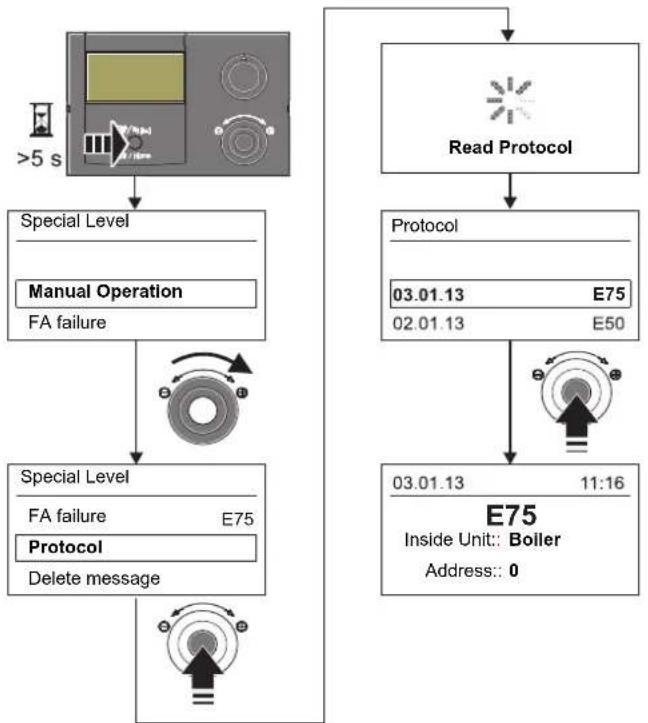
flowchart
graph TD
    A[">5 s"] --> B["Special Level"]
    B --> C["Manual Operation"]
    C --> D["FA failure"]
    D --> E["Special Level"]
    E --> F["FA failure E75"]
    F --> G["Protocol"]
    G --> H["Delete message"]
    H --> I["Read Protocol"]
    I --> J["Protocol"]
    J --> K["03.01.13 E75"]
    J --> L["02.01.13 E50"]
    K --> M["03.01.13 11:16"]
    L --> N["E75 Inside Unit:: Boiler"]
    N --> O["Address:: 0"]
Fig. 7-3 Reading the protocol
7.1.3 Troubleshooting
Information messages that are displayed without red back-lighting normally result in no permanent limitations on the operation of the Daikin RoCon.
Messages that are displayed with an error code E.... and red back-lighting required error correction by an authorised and trained expert heating technician.
For information on warning messages, see chap. 7.4.
• Detecting and remedying the cause of the malfunction.
- Contactor triggered:
Nothing shown on the display in the controller. Ascertain cause of triggering the contactor and remedy fault. Start the system again.
→ Once the cause has been remedied, the system will resume operations as normal.
- Contactor not triggered:
a) No error codes are shown, but the system is not working properly. Search for and rectify faults (see chap. 7.4).
→ Once the cause has been eliminated, the system continues to work normally.
b) Error codes are displayed as long as fault conditions are present. Search for and rectify faults (see chap. 7.4). If the fault message is still displayed after the cause of the fault has been corrected, the system must be disconnected from the power supply for at least 10 in order to unlock it.
→ Once the cause has been eliminated, the system continues to work normally.

To ensure that the error is not caused by incorrect settings, reset all parameters to the factory settings before any possible replacement of components (see chap. 3.6.12).
If you are unable to determine the cause of the fault yourself, please consult a Daikin service technician.
To do this, please have the important device data available (see fig. 7-4 for the procedure):
- Type and manufacturer number of the Daikin Altherma M ECH_2O (see heat pump type plate).
- Software versions (see fig. 7-4) of: a: RoCon B1 control panel [Sw Nr B1/U1] b: RoCon BM1 printed circuit board [Sw Nr Controller]
- For optional RoCon system components: U1 EHS157034 [Sw Nr B1/U1] M1 EHS157068 [Sw Nr mixing valve]

flowchart
graph TD
    A["Water Pressure"] --> B["Info"]
    B --> C["Overview"]
    C --> D["T-HS"]
    D --> E["Sw Nr Controller"]
    E --> F["Sw Nr Controller"]
    F --> G["366\nRev.: 04 A"]
    H["Sw Nr mixing valve"] --> I["Sw Nr B1/U1"]
    I --> J["Sw Nr B1/U1"]
    J --> K["Sw Nr B1/U1"]
    L["Sw Nr B1/U1"] --> M["399\nRev.: 02 F"]
    N["Sw Nr mixing valve"] --> O["368\nRev.: 01 B"]
Fig. 7-4 Software information of the controller components
7.2 Emergency operation
In the event of incorrect electronic controller settings or 3-way switch valve malfunctions, emergency heating operation can be maintained by activating the "Manual Operation" special function on the controller (see chap. 3.5.1 and the supplementary notes in the installation and maintenance instructions of the Daikin Altherma M ECH₂O).
7.3 EHS emergency operation
If the heat pump fails, the backup heater can be used as emergency heating, and can undertake all heating requirements either automatically or non-automatically (see chap. 3.4.13).
7.4 Malfunctions and fault codes
See Daikin Altherma M ECH _2 O installation and maintenance instructions; chapter entitled "Faults, malfunctions, messages".
8 Glossary
| Operating mode Heat generator function requested by the user or the controller (e.g. room heating, hot water preparation, Stand-by, etc.) | |
| Backup requirement | Operating situation in which the required feed temperature cannot be reached efficiently or at all using the heat pump process. A heater booster (e.g. a backup heater) is therefore integrated to support the Daikin Altherma M ECH2O in generating heat. |
| Backup heater | Optional electric heater booster for general support of the Daikin Altherma M ECH2O during heat generation. |
| Heating characteristic curve | Mathematical relationship between the external temperature and the target T-HS (synonym = heat slope) in order to achieve the desired room temperature at all outside temperatures. |
| Refrigerant A substance used | for heat transfer in the heat pump process. At low temperature and low pressure, heat is absorbed and at high temperature and a high pressure, heat is emitted. |
| Anti-legionella system | Periodic heating of the storage tank water to >60 °C to preventively kill pathogenic bacteria (Legionella) in the hot water circuit. |
| Modulation Automatic and stepless adjustment of the heating performance/pump performance to the respective heating requirement, without different heating/pump steps or cycles having to be switched. | |
| Off-peak mains connection (HT/NT) | A special mains connection to the energy supplier, which offers various cheaper rates during so-called low-load periods for electrical current (day-, night-, heat pump current, etc.). |
| Nominal output | Maximum heating performance, which the heat generator provides under test conditions for certain operating temperatures. |
| Parameters | A value that influences the execution of programs or processes or defines specific states. |
| Control unit | Device electronics that are used to control the processes for heat generation and heat distribution for the heating system. The control unit consists of a number of electronic components. The most important component for the operator is the control panel in the front area of the heat generator; it includes controls (rotary switches, rotary buttons, Exit button) and a display. |
| Return flow | Part of the hydraulic circuit that directs the cooled water from the radiators in the rooms back to the heat generator via the piping system. |
| Switching time program | Setting of weekdays and times on the controller to define regular heating, cooling, economy and hot water cycles. |
| Smart Grid (SG) | Intelligent use of energy for inexpensive heating. By using a special electricity meter, it is possible to receive a "Smart Grid signal" from the utility company.Depending on the signal, the heat pump is shut off, or operated as normal or at higher temperatures. |
| Flow | Part of the hydraulic circuit that diverts the heated water from the heat generator to the heating surfaces. |
| Domestic hot water circuit | The water circuit in which cold water is heated and conducted to the hot water tap. |
| Domestic hot water generation | Operating status of the heat generator in which heat with elevated temperatures is generated and fed to the hot water circuit, e.g. loading of the hot water storage tank. |
| Heat pump process | In a closed-loop refrigerant circuit, the refrigerant absorbs the heat from the ambient air. By means of compression, the refrigerant achieves a higher temperature which is transferred to the heating system (thermodynamic cycle). |
| Heat exchanger | A component that transfers thermal energy from one circuit to another. The two circuits are separated from each other hydraulically by a wall in the heat exchanger. |
| Water shortage/Overheating protection | Safety facility that shuts off the heat generator automatically in the event of a water shortage to prevent overheating. |
| Weather-dependent T-HS control | Target feed temperature determined from the measured value for the outside temperature and a defined heating curve for temperature control in the heater. |
| Circulation pump | Optional circulation pump that circulates the hot water in the circulation circuit (return from the tapping point to the hot water storage tank), thus making it available immediately at each tapping point. This circulation is especially useful in extensively branching pipe networks. In hot water distribution networks without circulation, the cooled water in the removal line first emerges during the tapping process until the removal line has been heated sufficiently by the inflowing hot water. |
| Heater booster | Additional heat generator (e.g. backup heater or external boiler) integrated in the heating system to achieve the required target feed temperature in the case of an inadequate or inefficient heat pump process. |
9 Notes
9.1 User-specific settings
9.1.1 Switching time program
The factory settings of the switching time programs are stated in chap. 3.4.7, tab. 3-9.
- Enter your switching time settings in the table below.
| Switching cycle 1 Switching | cycle 2 Switching cycle 3 | ||||||
| Temperature setting | [T-Room 1 Setpoint]: °C [T-Room 2 Setpoint]: °C [T-Room 3 Setpoint]: °C | ||||||
| Time period On | Off On Off On Off | ||||||
| HC Program 1 | Monday | ||||||
| Tuesday | |||||||
| Wednesday | |||||||
| Thursday | |||||||
| Friday | |||||||
| Saturday | |||||||
| Sunday | |||||||
| HC Program 2 | Monday | ||||||
| Tuesday | |||||||
| Wednesday | |||||||
| Thursday | |||||||
| Friday | |||||||
| Saturday | |||||||
| Sunday | |||||||
Tab. 9-1 Individual settings in the heating timer programs
| Switching cycle 1 Switching | cycle 2 Switching cycle 3 | ||||||
| Temperature setting | [T-DHW Setpoint 1]: °C [T-DHW Setpoint 2]: °C [T-DHW Setpoint 3]: °C | ||||||
| Time period On | Off On Off On Off | ||||||
| DHW Program 1 | Monday | ||||||
| Tuesday | |||||||
| Wednesday | |||||||
| Thursday | |||||||
| Friday | |||||||
| Saturday | |||||||
| Sunday | |||||||
| DHW Program 2 | Monday | ||||||
| Tuesday | |||||||
| Wednesday | |||||||
| Thursday | |||||||
| Friday | |||||||
| Saturday | |||||||
| Sunday | |||||||
| Switching cycle 1 Switching cycle 2 Switching cycle 3 | |||||||
| Off On Off On Off | |||||||
| Circulation Time | Monday | ||||||
| Tuesday | |||||||
| Wednesday | |||||||
| Thursday | |||||||
| Friday | |||||||
| Saturday | |||||||
| Sunday | |||||||
Tab. 9-2 Individual settings in the hot water timer programs
Tab. 9-3 Individual settings of the circulation switching time program
9.1.2 Parameters
- Enter the parameter changes you have made in the following table and in the Daikin Altherma M ECH₂O operating manual.
| Rotary switch setting | Parameter levels / Parameters | Old value | New value Date | Comments | |
Tab. 9-4 Individual parameter modifications
9.1.3 IDs in the RoCon CAN bus system
| RoCon device ID Comments | ||
Tab. 9-5 IDs in the RoCon CAN bus system
9 Notes
9.2 Other items
9 Notes
10 List of keywords
A
Additional heat generator .....24
Address switch 33, 34
Air purge .....25
Anti-legionella system ..... 26, 57
B
Backup heater ....10
Explanation .....57
Parameters 41, 44, 47
Backup requirement .....57
Basic functions
Automatic defrosting .....10
Displaying system information ....10
Setting the language, date and time 17
Switching the system on and off ...12
Water pressure display .....12
Bi-valence function .....41
Bus - Scan 17,49
C
Caretaker function .....35
Circulation pump 15,29
Cleaning 7
Cooling operation 13, 22
D
Data bus ..... 31, 40, 43, 49, 51, 52
Day mode .....14
Defrost function 10
Device ID 32, 33, 49, 55
Display 7
Domestic hot water generation .....14
E
Economy mode 13, 14
Emergency operation ....56
Error messages .....50
EVU 10
EVU function .....10
EVU function HT/NT .....11
EVU function SMART GRID .....11
Explanation of symbols 4,8
EXT signal .....11
External operating mode switch-over 13
F
Factory setting 40
Faults and malfunctions
Fault codes 56
Frost protection function ..... 8, 23
G
Glossary ....57
H
Heat generator ID 31,52
Heat slope .....21
Heating circuit ID 31, 32, 34, 35, 51, 52
Heating cycle .....15
Heating support function ..... 25, 41
Hot water recharging .....14
HT/NT function .....41
|
Information messages ..... 50, 55
K
Keylock 10
L
Language setting 17
Low tariff mains connection ..... 57
M
Malfunctions 55
Manual operation 20
Master-RoCon function .... 32, 35, 40
Mixer module 23, 33, 35
0
Operating data overview ..... 11
Operating elements 6,9
Exit key 9
Rotary button 9
Rotary switch 8
Operating modes
Automatic 1 13
Automatic 2 13
Buzzer 13
Cooling 13
Heating 13
Setback 13
Standby 12
P
Parameters 57
Pressure monitoring function ..... 45
Protocol 20
R
Relay test 29
Relevant documents 4
Remote control via Internet ..... 30
Reports 55
RESET 26
Room station 34
Room thermostat 41
Rotary switch position 9
S
Safety shutdown 6
Screed program
Function heating 27
Screed curing heating 27
Setting the date 17
Setting the time 17
SMART GRID 19,41,57
Software information ..... 10, 56
Special level 20
Switching time program ..... 14
Permanent programs 15
Personal settings 58
Setting 14
Temporary programs ..... 16
System temperatures 10
T
Target feed temperature ..... 13
for cooling mode 22
with heating mode 21
with weather-dependent control .. 23
Target hot water temperature
13, 14, 20
Target room temperature ..... 14
Technician code 21,40
Temperature setting
Day mode 14
Domestic hot water mode ..... 14
Economy mode 14
Terminal address 34
Terminal function ..... 17, 49, 51
Terminal ID .23, 31, 32, 33, 34, 43, 52
Terminal operation 18
Time programs (temporary)
Away 16
Holiday 16
Party 16
U
Use as intended 5
W
Water pressure 12
Whisper mode 18,44
Z
Zone control 23
- Operating instructions
- Safety 4
- Product description.... 6
- Operation 7
- Initial start-up 31
- Parameter overview. 36
- Parameter settings 40
- Errors, malfunctions and messages ..... 55
- Glossary....57
- Notes ....58
- List of keywords .....63
- Safety
- Refer to the manual
- Relevant documents
- Warning signs and explanation of symbols
- Meaning of the warnings
- DANGER!
- WARNING!
- CAUTION!
- Special warning signs
- Validity
- Handling instructions
- Display readouts of the RoCon controller
- Avoiding danger
- Use as intended
- Product description
- Operation
- General
- Maximum energy exploitation
- Display
- Controls
- Rotary switch
- Rotary button
- Exit key
- Operating concept
- Keylock
- Basic functions and operating modes
- Without backup heater:
- With backup heater (EKBUxx):
- Automatic defrost function
- System information (Info)
- Displaying the operating data overview
- Displaying the water pressure
- Setting the operating mode
- Operating mode Standby (Stand-by)
- Operating mode Reducing
- Heating, Cooling
- Operating mode Summer
- Operating mode Automatic 1 (time program)
- Operating mode Automatic 2 (time program)
- Switching contact for external operating mode switch-over
- Temperature setting of daytime room temperature
- Temperature setting of setback mode
- Temperature setting of hot water generation
- Unscheduled hot water preparation
- Switching time program
- Setting
- Permanent time programs
- Temporary time programs
- System settings
- Setting the LCD display, language, date, time
- Terminal function
- Activating/deactivating terminal operation
- Operation with glycol
- Whisper mode
- Activating / deactivating whisper mode
- Smart Grid (SG)
- EHS emergency operation
- Activating / deactivating emergency automatic operation
- Special functions
- Manual operation
- 3-way switching valves reference travel
- Special system settings
- Access rights (technician code)
- Heat slope
- Caution - Risk of overheating of floor heating!
- Manually adjusting the heat slope
- Cooling slope
- Caution - risk of condensation!
- Prerequisites for cooling mode:
- Weather-dependent T-HS control
- With connected mixer module M1
- Frost protection function
- Interlink function
- Additional alternative heat generator
- Heating support
- Special function: switching contacts
- Air purge
- Anti-legionella system
- Resetting to factory settings (reset)
- Option 1
- Option 2
- Option 3
- Screed program
- Function heating
- Screed curing heating
- Setting and starting the screed program
- Relay test
- Settings for optional circulation pump
- Defining the switching time program for the circulation pump
- Remote control via Internet
- Initial start-up
- i
- Fundamental aspects of the IDs and authorisations in the RoCon system
- For the EHS157034 room station
- For all RoCon B1 and EHS157034 control units
- Operating Support during 1st.
- Commissioning and during System Extensions
- Commissioning Daikin Altherma M ECH _2 O
- Assigning the terminal ID on the RoCon B1 control panel of the Daikin Altherma M ECH₂O
- Putting optional RoCon system components into operation
- M1 Mixer module EHS157068
- EHS157034 room station
- Sequence for initial commissioning (see also c#.2).
- A: Configuration for the "Living Room" setting
- B: Configuration for "Mixing Valve" setting
- Allocating the EHS157068 mixing module to a heat generator
- Master RoCon function
- Caretaker function
- Parameter overview
- For first commissioning or resetting to factory settings
- During initial commissioning: After resetting to factory settings:
- After first commissioning/After successful basic configuration
- Rotary switch setting: DHW Install
- Rotary switch setting: Operating Mode
- Rotary switch setting: Set Temp Day
- Rotary switch setting: Set Temp Night
- Rotary switch setting: DHW Set Temp
- Rotary switch setting: Time Program
- Rotary switch setting: Remote Param
- Rotary switch setting: Info ⓘ
- Exit key: Special function
- M1 Parameter levels for the EHS157068 mixer module
- Rotary switch setting: Info ①
- Rotary switch setting: Operating Mode
- Rotary switch setting: Set Temp Day
- Rotary switch setting: Set Temp Night
- Rotary switch setting: DHW Set Temp
- Rotary switch setting: DHW Install
- Rotary switch setting: Time Program ☑
- Rotary switch setting: Remote Param
- Rotary switch setting: Configuration
- Parameter settings
- Explanation of the parameter tables
- Rotary switch setting: Configuration
- "Setup" level
- "DHW Configuration" level
- Rotary switch setting: DHW Install
- Exit key: Special function
- "Basic Configuration" parameter level
- Parameter levels of the EHS157068 mixer module
- Rotary switch setting: Info ⓘ
- Errors, malfunctions and messages
- Recognising errors, correcting malfunctions
- Current error display
- Reading out the protocol
- Troubleshooting
- Emergency operation
- EHS emergency operation
- Malfunctions and fault codes
- Notes
- User-specific settings
- Switching time program
- Parameters
- Other items
- List of keywords
- A
- B
- C
- D
- E
- F
- G
- H
- |
- K
- L
- M
- 0
- P
- R
- S
- T
- U
- W
- Z
Brand : DAIKIN
Model : EKHWMX300CA
Category : Chauffe-eau instantané et chauffe-eau