
S108 - Network switch PULSAR - Free user manual and instructions
Find the device manual for free S108 PULSAR in PDF.


| Product Type | Thermal Imaging Monocular |
| Brand | Pulsar |
| Model | S108 |
| Dimensions (L x W x H) | 155 x 61 x 62 mm |
| Weight | 280 g |
| Power Source | 2x CR123 3V Lithium batteries |
| Battery Life | Up to 5 hours continuous use |
| Display Type | AMOLED 640x480 pixels |
| Sensor Resolution | 320x240 pixels 17 µm |
| Detection Range | Up to 800 m (human size) |
| Optical Magnification | 2x |
| Digital Zoom | Up to 4x stepwise |
| Frame Rate | 50 Hz |
| Operating Temperature Range | -10°C to +50°C |
| Waterproof Rating | IPX7 (1 m depth, 30 min) |
| Main Functions | Observation, image & video capture, crosshair selection, Wi-Fi connectivity |
| Controls | 4 push buttons, focus ring, diopter adjustment |
| Accessories Included | USB cable, carrying pouch, cleaning cloth, strap, user manual |
| Maintenance | Clean lens with soft, dry cloth. Remove batteries for long-term storage. Keep in a cool, dry place. |
| Safety Precautions | Do not point lens at strong light sources. Avoid impact. Do not disassemble. Use only recommended batteries. |
| Repairability | Battery compartment user-accessible. Internal repairs only by authorized service centers. |
| Warranty | 2 years limited warranty |
Frequently Asked Questions - S108 PULSAR
User questions about S108 PULSAR
0 question about this device. Answer the ones you know or ask your own.
Ask a new question about this device
Download the instructions for your Network switch in PDF format for free! Find your manual S108 - PULSAR and take your electronic device back in hand. On this page are published all the documents necessary for the use of your device. S108 by PULSAR.
USER MANUAL S108 PULSAR
Supercedes the edition: 5 from 04.02.2019
EN**
Features:
- Switch 10 ports
8 PoE ports 10/100Mb/s (data and power supply) 2 ports 10/100Mb/s (UP LINK) - Long Range mode (up to 250m)
-
30 W for each PoE port, supports devices complaint with the IEEE802.3af/at (PoE+) standard
• Supports auto-learning and auto-aging of MAC addresses (1K size) -
The PSD 520230 V DC/2,3 A/120 W max. power supply desktop type included
• Additional assembly elements - LED indication
- warranty – 2 year from the production date
Example of use.
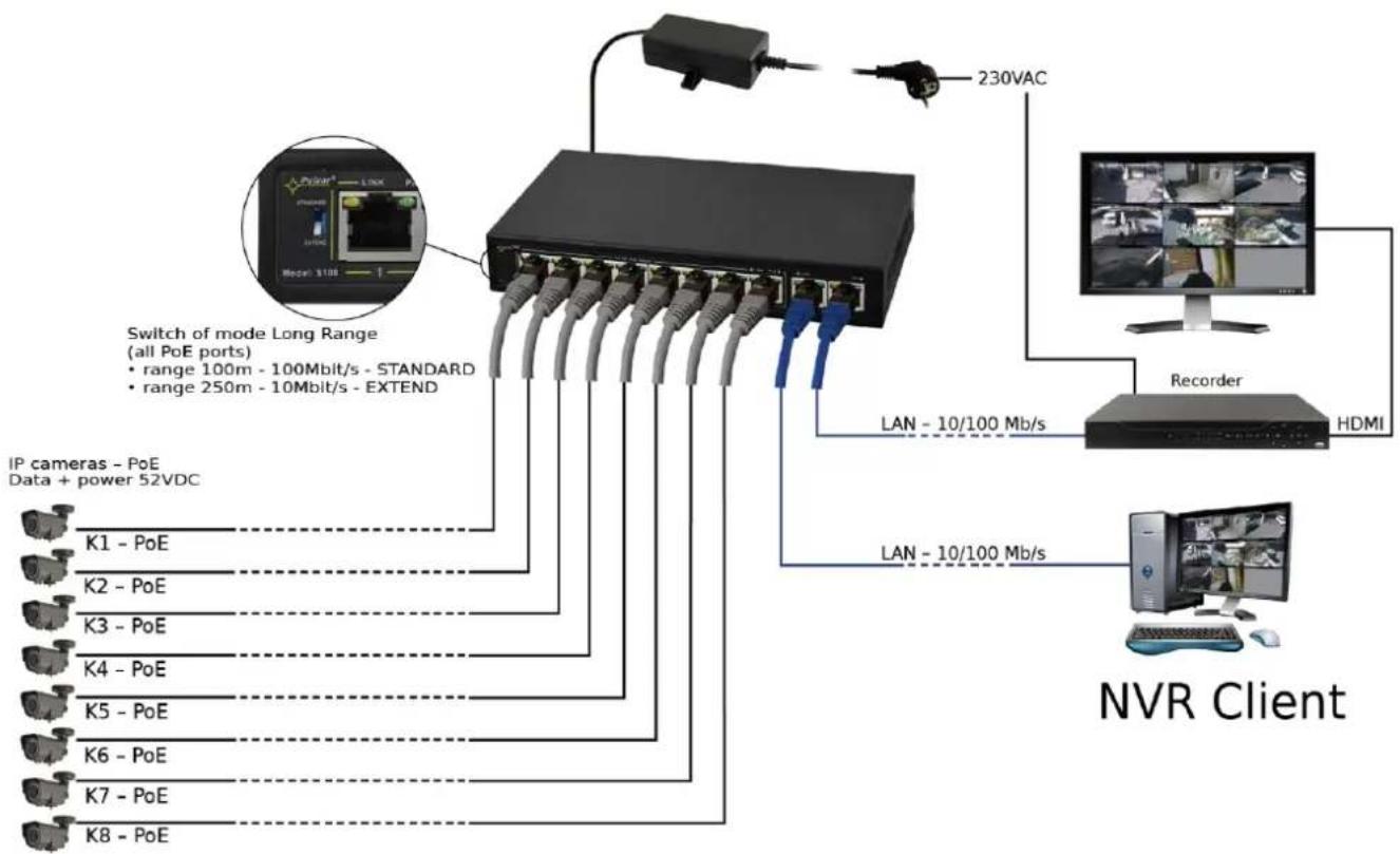
flowchart
graph TD
    A["NVR Client"] --> B["IP cameras - PoE Data + power 52VDC"]
    A --> C["Switch of mode Long Range (all PoE ports)"]
    A --> D["LAN - 10/100 Mb/s"]
    A --> E["Recorder"]
    A --> F["230VAC"]
    B --> G["K1 - PoE"]
    B --> H["K2 - PoE"]
    B --> I["K3 - PoE"]
    B --> J["K4 - PoE"]
    B --> K["K5 - PoE"]
    B --> L["K6 - PoE"]
    B --> M["K7 - PoE"]
    B --> N["K8 - PoE"]
    C --> O["Monitor"]
    D --> P["HDMI"]
    E --> Q["Computer"]
1. Technical description
1.1. General description.
S108 is a 10-ports PoE switch designed to supply IP cameras operating in IEEE 802.3af/at standard. Automatic detection of any devices powered in the PoE/PoE+ standard is enabled at the 1 – 8 ports of the switch. The UP LINK ports is used for connection of another network device via RJ45 connector. The LEDs at the front panel indicate the operation status (description in the table below).
The PoE technology ensures a network connection and reduces installation costs by eliminating the need to supply a separate power cable for each device. This method allows supplying other network devices, such as IP phone, wireless access point or router.
1.2 Block diagram.

flowchart
graph LR
    A["Power Source"] --> B["The PSD 520230 52 V DC / 2.3 A/120W max power supply desktop type"]
    B --> C["Switch 10-Ports ETHERNET SWITCH 10/100 with 8 PoE ports + 2 x UP LINK"]
    C --> D["Data (twisted pair cat. 5)"]
    C --> E["Client NVR"]
    D --> F["RECORDER VIDEO (NVR)"]
    E --> G["CAMERA 1"]
    E --> H["CAMERA 2"]
    E --> I["CAMERA 3"]
    E --> J["CAMERA 4"]
    E --> K["CAMERA 5"]
    E --> L["Camera 6"]
    E --> M["Camera 7"]
    E --> N["Camera 8"]
    C --> O["Data + power supply (twisted pair cat. 5)"]
    C --> P["Data + power supply (twisted pair cat. 5)"]
Fig. 1. Block diagram.
1.3 Description of components and connectors.
Table 1. (See Fig. 2)
| Component No.(Fig. 2) | Description |
| [1] | 8 x PoE ports (1÷8) |
| [2] | 2 x UP LINK port |
| [3] | Power Socket of the DC |
| [4] | Additional assembly elements |
| [5] | Switch of mode Long Range |

Fig. 2. The view of the switch.
1.4 Technical parameters
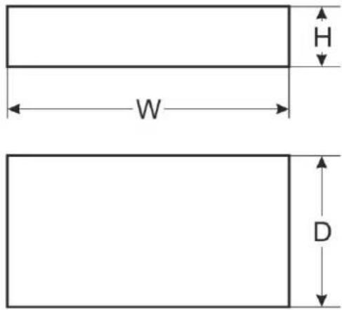
Table 2.
| Ports | 10 ports 10/100Mb/s (8 x PoE + 2 x UP LINK)with connection speed auto-negotiation and MDI/MDIX Auto Cross) |
| PoE power supply | IEEE 802. 3af/at (1÷8 ports), 52 V DC / 30 W at each port * |
| Long Range mode | Long Range, VLAN |
| Protocols, Standards | IEEE802.3, 802.3u, 802.3x CSMA/CD, TCP/IP |
| Bandwidth | 1,6Gbps |
| Transmission method | Store-and-Forward |
| Optical indication of operation | Switch power supply;Link/Act;PoE Status |
| Power supply | ~100 ÷ 240 V; 50/60 Hz;1,3 Athe PSD 520230 52 V DC/2,3 A/120 W max. power supply desktop type |
| Operating conditions | temperature -10°C ÷ 40°C,relative humidity 5% - 90%, no condensation |
| Dimensions | W=190, H=28, D=105 [+/- 2mm] |
| Additional equipment | plate to be fixed surface |
| Gross/Net weight | 1,2 / 1,4kg |
| Protection classEN 60950-1:2007 | II (second) |
| Storage temperature | -20°C ÷ 60°C |
| Declarations | CE |
* The given value of 30 W per port is the maximum value. The total power consumption should not exceed 96 W.
2. Installation
2.1. Requirements
The unit should be mounted in confined spaces, in accordance with the 2nd environmental class, with normal relative humidity (RH=90% maximum, without condensation) and temperature from -10°C to +40°C. Ensure the free flow of air around the unit. The PSU shall work in a vertical position that guarantees sufficient convectional air-flow through ventilating holes of the enclosure.
The switch load balance should be done before installation. The given value of 30 W per port is the maximum value referring to a single output. The total power consumption should not exceed 96 W. The increased demand for power is particularly evident in the case of cameras with heaters or infrared illuminators - when launching these features, the power consumption increases rapidly, which may adversely affect the operation of the switch. As the device is designed for a continuous operation and is not equipped with a power-switch, therefore an appropriate overload protection in the power supply circuit should be provided. The electrical system shall be made in accordance with applicable standards and regulations.
2.2. Long Range mode
Switch enables operation in two modes: standard and extended range. When the Long Range switch is in STANDARD position (see Fig. 5), PoE ports operate at 100 Mb / s up to 100 meters. After switching to EXTEND position, range is increased to 250 meters and speed is reduced to 10 Mb / s. Additionally, VLAN function, which isolates the PoE ports between each other (communication takes place between the UpLink ports and individual PoE), is activated. In both modes, the UpLink port speed is 100 Mb / s.
Note: Changing the modes requires a power restart!
2.3. Installation procedure
- Connect switch to the PSD520230 52 V DC power supply unit desktop type.
- Connect the power supply to the 230 V socket.
- Connect the camera wires to the RJ45 connectors (connectors PoE).
- Check the optical indication of switch operation (see Table 3).
Connection schemes

flowchart
graph TD
    subgraph Top架构
        A["Data + Power"] --> B["PGE Switch S100"]
        B --> C["Monitor"]
        D["Data"] --> E["NVR Client"]
        F["Data + Power"] --> G["PGE IP Camera 5"]
        G --> H["Computer"]
        I["Data"] --> J["NVR Client"]
    end
    subgraph Bottom架构
        K["PGE Switch O100"]
        L["PGE IP Camera 3"]
        M["NVR Client"]
        N["Data + Power"] --> O["PGE IP Camera 7"]
        P["Data"] --> Q["NVR Client"]
        R["Data + Power"] --> S["PGE IP Camera 6"]
        T["Data"] --> U["NVR Client"]
    end
    A --> V["Pod IP Camera 1-4"]
    B --> W["Pod IP Camera 5"]
    C --> X["Pod IP Camera 6"]
    D --> Y["Pod IP Camera 7"]
    E --> Z["Pod IP Camera 8"]
    F --> AA["Pod IP Camera 9"]
    G --> AB["Pod IP Camera 10"]
    H --> AC["Pod IP Camera 11"]
    I --> AD["Pod IP Camera 12"]
    J --> AE["Pod IP Camera 13"]
    K --> AF["Pod IP Camera 14"]
    L --> AG["Pod IP Camera 15"]
    M --> AH["Pod IP Camera 16"]
    N --> AI["Pod IP Camera 17"]
    O --> AJ["Pod IP Camera 18"]
    P --> AK["Pod IP Camera 19"]
    Q --> AL["Pod IP Camera 20"]
    R --> AM["Pod IP Camera 21"]
    S --> AN["Pod IP Camera 22"]
    T --> AO["Pod IP Camera 23"]
    U --> AP["Pod IP Camera 24"]
    V --> AQ["Pod IP Camera 25"]
    W --> AR["Pod IP Camera 26"]
    X --> AS["Pod IP Camera 27"]
    Y --> AT["Pod IP Camera 28"]
    Z --> AU["Pod IP Camera 29"]
    AA --> AV["Pod IP Camera 30"]
    AB --> AW["Pod IP Camera 31"]
    AC --> AX["Pod IP Camera 32"]
    AD --> AY["Pod IP Camera 33"]
    AE --> AZ["Pod IP Camera 34"]
    AF --> BA["Pod IP Camera 35"]
    AG --> BB["Pod IP Camera 36"]
    AH --> BC["Pod IP Camera 37"]
    AI --> BD["Pod IP Camera 38"]
    AJ --> BE["Pod IP Camera 39"]
    AK --> BF["Pod IP Camera 40"]
    AL --> BG["Pod IP Camera 41"]
    AM --> BH["Pod IP Camera 42"]
    AN --> BI["Pod IP Camera 43"]
    AO --> BJ["Pod IP Camera 44"]
    AP --> BK["Pod IP Camera 45"]
    AQ --> BL["Pod IP Camera 46"]
    AR --> BM["Pod IP Camera 47"]
    AS --> BN["Pod IP Camera 48"]
    AT --> BO["Pod IP Camera 49"]
    AU --> BP["Pod IP Camera 50"]
    AV --> BQ["Pod IP Camera 51"]
    AW --> BR["Pod IP Camera 52"]
    AX --> BS["Pod IP Camera 53"]
3. Operation indication.
Table 3. Operation indication
OPTICAL INDICATION AT THE PoE PORTS (1÷8)
| GREEN LED LIGHT (PoE)Indication of the PoE powersupply at the RJ45 ports |  | OFF- no power supply at the RJ45 port (the device is not connected or not compliant with the IEEE802.3af/at standard)ON - power supply at the RJ45 portBlinking - short-circuit or output overload |
| YELLOW LED LIGHT (LINK)The connection status of LANdevices 10/100Mb/sand data transmission |  | OFF- no connectionON - the device is connected 10/100Mb/sBlinking - data transmission |
OPTICAL INDICATION AT THE UP LINK PORTS
| GREEN LED LIGHT |  | Port on the left side:No lit - no voltageLit – switch operates properly | Port on the right side:No lit – switch operates in normal modeLit– Long Range mode active |
| YELLOW LED LIGHT (LINK)The connection status of LAN devices 10/100Mb/s and data transmission |  | OFF- no data transmissionON - the device is connected 10/100Mb/sBlinking – data transmission | |

WEEE LABEL
Waste electrical and electronic equipment must not be disposed of with normal household waste. According to the European Union WEEE Directive, waste electrical and electronic equipment should be disposed of separately from normal household waste.
Pulsar sp. j.
Siedlec 150, 32-744 Łapczyca, Poland Tel. (+48) 14-610-19-40, Fax. (+48) 14-610-19-50 e-mail: biuro@pulsar.pl, sales@pulsar.pl http://www.pulsar.pl, www.zasilacze.pl
Brand : PULSAR
Model : S108
Category : Network switch