
VR-120HD - Table de mixage audio-vidéo ROLAND - Free user manual and instructions
Find the device manual for free VR-120HD ROLAND in PDF.


| Product Type | Direct Streaming AV Mixer |
| Video Processing | 4:2:2 (Y/Pb/Pr), 8-bit |
| Number of Video Input Channels | 12 (6x HDMI, 6x SDI) |
| Video Input Connectors | HDMI IN 1-6 (Type A), SDI IN 1-6 (BNC) |
| Video Output Connectors | HDMI OUT 1-3 (Type A), SDI OUT 1-3 (BNC), USB STREAM (USB Type-C) |
| Audio Channels | 42 channels (24-bit/48 kHz) |
| Audio Input Connectors | 6x Combo (XLR/TRS), 2x RCA (L/R), 2x RCA (L/R), Bluetooth, USB, HDMI/SDI embedded |
| Audio Output Connectors | 2x XLR (Main), 2x XLR (Aux), 2x RCA, Headphones (1/4" and mini), USB, HDMI/SDI embedded |
| Display | 7" touch screen, 800x480, color LCD |
| Bluetooth | Version 5.0, A2DP, GATT (MIDI over BLE) |
| Streaming | Direct Stream port (RJ45, Gigabit Ethernet), supports YouTube, Facebook, Twitch |
| Recording Media | SD/SDHC/SDXC card, USB flash drive (FAT32) |
| Still Image Support | BMP, PNG (alpha), JPEG up to 1920x1080, 16 internal memory slots |
| Video Playback | MP4 (H.264 up to 1080/60p, AAC), 1 slot |
| Video Effects | Cut, Mix (Dissolve/Fam/Nam), Wipe (8 types), Split (2 types), PiP (4 layers), Keyer (4), DSK (2) |
| Audio Effects | HPF, Echo canceller, Anti-feedback, Noise gate, De-esser, Compressor, 4-band EQ, Voice changer, Delay, Auto mixing, Reverb, Loudness AGC, Adaptive Noise Reduction, 15-band GEQ |
| Scene Memory | 32 memories |
| Macro / Sequencer | 100 macros, 1000-step sequencer |
| Auto Switching Modes | Input scan, Scene memory scan, Beat sync, Video follows audio, PiP&Key scan, DSK scan |
| Dimensions (W x D x H) | 437 x 304 x 109 mm (without rack angles); 482 x 304 x 109 mm (with angles) |
| Weight | 5.3 kg (11 lb 11 oz) excluding AC adaptor |
| Power Consumption | 69 W (AC adaptor, 3.0 A) |
| Accessories | Startup guide, safety leaflet, AC adaptor, power cord, rack-mount angles & screws |
Frequently Asked Questions - VR-120HD ROLAND
User questions about VR-120HD ROLAND
0 question about this device. Answer the ones you know or ask your own.
Ask a new question about this device
Download the instructions for your Table de mixage audio-vidéo in PDF format for free! Find your manual VR-120HD - ROLAND and take your electronic device back in hand. On this page are published all the documents necessary for the use of your device. VR-120HD by ROLAND.
USER MANUAL VR-120HD ROLAND
Panel Descriptions....4
◇ Top Panel....4
◇ Front Panel ....6
◇ Rear Panel ....7
Connecting Bluetooth ^® Devices 8
Registering a Bluetooth Audio Device (Pairing)....8 Connecting an Already-Paired Bluetooth Device....8
◇ Connecting a Footswitch....9
◇ Turning the Power On/Off 10
Operating the Menu 10
Operating the Setup Screen 11
◇ Switching the Monitor View 12
◇ About SD Card.... 13
Inserting the SD Card .... 13 Formatting an SD Card .... 13 Removing an SD Card.... 13
◇ About USB Flash Drive 13
Formatting a USB Flash Drive .... 13 Removing a USB Flash Drive .... 13
Video Input/Output Settings.... 14
Setting the Video Input/Output Format 14
Setting the System Format.... 14 Setting the Input Format for the HDMI IN 1–6 Connectors ... 14
◇ Assigning Video Sources .... 15
◇ Adjusting Output Video 15
◇ Adjusting Input Video.... 16
◇ Assigning Video Buses to Output Connectors ..... 17
◇ Selecting the Video Sent to the AUX Bus 18
◇ Inputting Copy-Protected (HDCP) Video 18
◇ Specifying a Reference Clock 19
Video Operations 20
◇ Switching the Video.... 20
Setting the Operation Mode .... 20 Switching in the Dissolve Mode .... 20 Switching in the PGM/PST Mode .... 21 Changing the Mix Pattern .... 21 Changing the Wipe Pattern .... 21
Splitting the Video 22
Configuring the Screen Layout 22 Displaying the Split 22
◇ Switching the Video Automatically (Auto Switching).... 23
About the Operation Mode....23 Turning the Auto Switching Function On/Off....23 Setting the Operation Mode....23
◇ Loading a Still Image.... 27
Loading a Still Image from a Storage 27 Capturing a Still Image from Input/Output Video 28
◇ Outputting a Loaded Still Image.... 28
Assigning a Still Image to the VIDEO SWITCHER Buttons ..... 28 Inserting a Still Image in the Final Output..... 28
◇ Deleting a Still Image 29
◇ Saving a Still Image to a SD Card or USB Flash Drive .... 30
◇ Importing a Video.... 31
◇ Outputting a Loaded Video.... 32
Playing Back a Video (with the Video Player) .... 32 Assigning Videos to the VIDEO SWITCHER Buttons .... 32 Inserting a Video in the Final Output .... 32
◇ Freezing the Input Video (Freeze).... 33 Setting the Operation Mode.... 33 Freezing the Input Video.... 33
◇ Fading-In/Out the Final Output Video.... 34
Video Composition Operations 35
◇ Compositing Video with Picture-in-Picture (PinP).... 35 Making Detailed Settings for the Inset Screen.... 36
◇ Compositing Video with Downstream Keyer (DSK) .... 38 About DSK Mode.... 38 Compositing a Caption or Image (Luminance Key).... 39 Compositing a Subject and Background (Chroma Key).... 40 Compositing a Still Image with Alpha Channel.... 42 Using an External Key.... 43 Swapping and Copying Settings.... 44
Audio Operations 45
◇ Assigning Audio Sources to Audio Channels ..... 45
◇ Adjusting the Input Gain (Sensitivity) 45
Adjusting the Volume Balance.... 46 Adjusting the Volume Balance from the Mixer Screen .... 47
◇ Applying Effects to Input Audio .... 48 Using an Effect Preset .... 49 Reducing Acoustic Feedback (Anti-Feedback) .... 50 Changing the Character of a Voice (Voice Changer) .... 50 Applying Reverb .... 51
◇ Applying Effects to Output Audio.... 52
- Interlinking Audio Output to Video Switching (Audio Follow) 52 Adding an Object for Audio Follow .... 52 - Removing Noise from the Audio (Adaptive Noise Reduction / Low Frequency Cut ) .... 53 - Automatically Setting a Comfortable Volume (Auto Mastering Effect).... 54 Loudness Auto Gain Control (Loudness AGC) .... 54
◇ Controlling the Volume Automatically (Auto Mixing) ... 55
Silencing Only Specific Audio (Mute)....56 Muting Input Audio....56 Muting the Output Audio....56
◇ Checking a Specific Audio Input (Solo) .... 57 Soloing the Input Audio .... 57 Soloing the Output Audio .... 57
Playing Back Audio Files (Audio Player) 58
Importing an Audio File 58
Playing Back Audio Clips 58
Setting an Audio Clip 59
Mixer Settings for the Audio Player 60
◇ Outputting AUX-bus Audio....61 Assigning the AUX Bus....61 Sending Audio to the AUX Bus....61
◇ Adding Input Audio to an HDMI or SDI Video for Output 62
Live Streaming 63
◇ Outputting Video/Audio to a Computer for Streaming.. 63 Outputting Video and Audio to the Computer .... 63 Using the Loopback Function .... 63
Streaming Video from a Computer.... 63
Capturing Video on the Computer 63
◇ Streaming/Capturing Video Directly 64
Network Requirements.... 64
Points to Be Aware of When Livestreaming 64
Starting/Stopping the Livestream, Audio or Video Recording 64
Turning Livestreaming, Audio and Video Recording ON/OFF . 64
Livestreaming via YouTube Live 65
Livestreaming via Facebook Live 66
Livestreaming via Twitch 67
Streaming with Custom Settings 68
Tethering....69
Avoiding Sporadic Issues When Livestreaming (Safety Delay) 70
Other Functions....71
◇ Saving/Recalling Settings (Scene Memory)....71
Saving to a Scene Memory....71
Recalling a Scene Memory....72
Initializing a Scene Memory.... 72
Renaming a Scene Memory....72
Changing the Thumbnail Position 73
Saving Scene Memories to an SD Card or USB Flash Drive.... 73
◇Recording Multiple Operations to Automatically Execute (Macros)....75
Recording a Macro....75
Executing a Macro....77
Copying Macro Settings.... 78
Swapping the Macro Settings 78
Initializing a Macro 79
Renaming a Macro....79
Saving/Loading the Macro Settings....80
Initializing All Macros 81
◇Combining Scene Memories and Macros for Operations (Sequencer)....82
Recording to the Sequencer 82
Running the Sequencer 84
Making the Sequencer Run Automatically (Auto Sequence).. 85
Saving/Loading the Sequencer Settings.... 86
Initializing the Sequencer.... 87
◇ Backing Up and Restoring the Unit's Settings 88
Backing Up 88
Restoring....89
◇ Assigning Functions to the USER Buttons ..... 90
◇Controlling an External Recorder's Video Record Start/Stop from the VR-120HD 90
◇ Remotely Controlling a PTZ Camera 91
Network Settings on the Camera 91
Registering Camera Settings in a Preset 91
Recalling a Preset.... 92
◇ Using a Footswitch.... 93
◇ Using an Expression Pedal.... 94
Adjusting the Pedal (Pedal Calibration) 94
Assigning a Function to the Pedal 94
◇ Control Using the TALLY/GPIO Connector ..... 95
Specification of the TALLY/GPIO Connector 95
Inputting a Control Signal 95
Outputting a Tally Signal 96
Outputting a Control Signal.... 96
◇ Using Smart Tally 97
Connecting via a Wireless LAN Router.... 97
Starting Smart Tally 97
◇ Preventing Unintended Operation (Panel Lock) ..... 98
◇ Returning to the Factory Settings (Factory Reset).... 99
◇ Remotely Controlling the VR-120HD 100
Menu List.... 101
1: Video Assign.... 101
2:Video Input 103
3:Video Output 104
4: Transition.... 105
5: PinP & Key 106
6: DSK 108
7: Audio Fader Assign 109
8: Audio Input.... 110
9: Audio Output.... 128
10: Audio Follow 136
11: Audio Auto Mixing.... 136
12: Audio Player.... 137
13: Stream/Record 137
14: Scene Memory 138
15: Macro 139
16: Sequencer.... 139
17: Still Image.... 140
18: Video Player 140
19: Freeze.... 140
20: Auto Switching 141
21: Ctl/Exp 142
22: RS-232/Tally/GPO/GPI.... 144
23: Network....146
24: Camera Control.... 147
25: SD Card/USB Memory 147
26: System 148
Appendix....154
◇ About Rack Mounting.... 154
Attaching the Rack-Mount Angles 154
Important Notes on Rack Mounting.... 154
◇ Main Specifications 155
Dimensions.... 159
◇ Video Block Diagram.... 160
Audio Block Diagram.... 161
- The Bluetooth® word mark and logos are registered trademarks owned by Bluetooth SIG, Inc. and any use of such marks by Roland is under license.
- QR Code is a registered trademark of DENSO WAVE INCORPORATED in Japan and in other countries.
- Roland is an either registered trademark or trademark of Roland Corporation in the United States and/or other countries.
• Company names and product names appearing in this document are registered trademarks or trademarks of their respective owners.
Top Panel
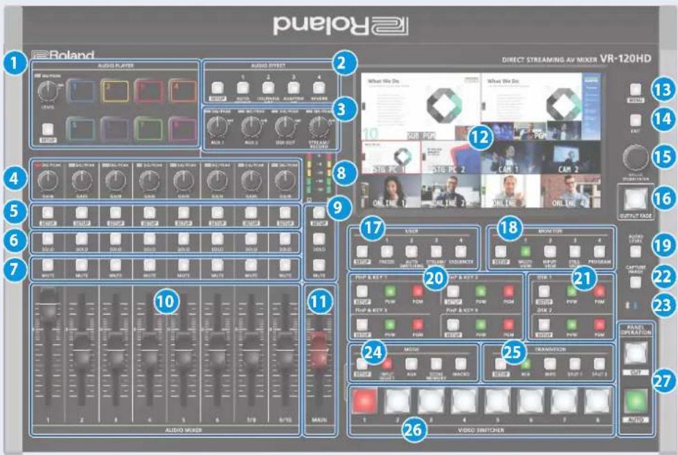
1 AUDIO PLAYER
This section lets you assign sound sources such as background music, sound effects and so on to the pads and then play them back.
* You can use an audio file (WAV format) stored on a USB flash drive or an SD card as the source.
[LEVEL] knob
Adjusts the playback volume of the sound source.
SIG/PEAK indicator
These indicators light up when audio output is detected.
Lit red Excessive volume (0 dB and above)
Lit yellow Appropriate volume (-20 to -1 dB)
Lit green Insufficient volume (-50 to -21 dB)
[SETUP] button
Shows the setup screen in the display.
Pads [1]-[8]
Press a pad to play back the assigned sound source.
2 AUDIO EFFECT
[1]–[4] buttons
Press to turn the audio effects on/off. You can also assign different functions to each button.
[SETUP] button
Shows the setup screen in the display.
Adjusts the volume of the AUX bus output.
[USB OUT] knob
Adjusts the volume of the USB output.
[STREAM/RECORD] knob
Adjusts the volume of streaming/recording.
SIG/PEAK indicators
These indicators light up when audio output is detected.
Lit red Excessive volume (0 dB and above)
Lit yellow Appropriate volume (-20 to -1 dB)
Lit green Insufficient volume (-50 to -21 dB)
4 [GAIN] knobs
Adjust the gain (sensitivity) of the audio that is being input from the AUDIO IN 1–9/10 jacks.
SIG/PEAK indicators
These indicators light up when audio input is detected.
Lit red Excessive volume (0 dB and above)
Lit yellow Appropriate volume (-20 to -1 dB)
Lit green Insufficient volume (-50 to -21 dB)
5 [SETUP] buttons
Shows the setup screen in the display.
6 [SOLO] buttons
Press these buttons to allow only the audio of the selected input channels to be output. When this is turned on (the button lights up) for a channel, you can monitor the pre-fader audio for that channel through headphones.
7 [MUTE] buttons
Press these buttons to mute (silence) the audio of the selected input channels.
8 Level meters
Shows the main output level.
9 [SETUP] button, [SOLO] button, [MUTE] button
These buttons are for the main output.
10 [1]–[9/10] faders
These adjust the input volume for each channel.
11 [MAIN] fader
Adjusts the output volume.
12 Display (Touch Panel)
Shows the status of the input/output video and of streaming/ recording, as well as the parameters and menus.
13 [MENU] button
Switches the menu screen between visible and hidden.
14 [EXIT] button
Exits a menu level or cancels an operation.
15 [VALUE] knob
| Turn Selects the menu parameters and edits their values. | |
| Press | Confirms the menu item you selected or the value that you edited. |
16 [OUTPUT FADE] button
The final output video and audio fade in/out.
| Lit Fade-out completed |
| Blink Fading-in/out |
| Unlit Normal output |
17 USER
[1]–[4] buttons
These buttons execute pre-assigned functions.
With the factory settings, the buttons are assigned as follows.
| Button | Explanation |
| USER [1] | FREEZETurns the freeze function (freeze the input video) on/off. |
| USER [2] | AUTO SWITCHINGTurns the auto switching function (used to automatically switch between videos) on/off. |
| USER [3] | STREAM/RECORDShows the STREAM/RECORD setup screen in the display. |
| USER [4] | SEQUENCERTurns the sequencer function on/off. |
[SETUP] button
Shows the setup screen in the display.
18 MONITOR
[1]–[4] buttons
Switches between video signals to monitor on the built-in display (monitor).
| button Explanation | |
| MONITOR [1] | MULTI-VIEWThe final output video, preview output video and the videos allocated to the VIDEO SWITCHER [1]-[8] buttons are shown in sections of the display. |
| MONITOR [2] | INPUT-VIEWThe input video from the HDMI IN and SDI IN connectors and other sources are shown as 16 separate sections on the screen. |
| button Explanation | |
| MONITOR [3] | STILL-VIEWShows the loaded still images in 16 separate sections on the screen. |
| MONITOR [4] | PROGRAMShows the final output video. |
* The settings described above are the factory defaults. You can also assign different functions to each button.
[SETUP] button
Shows the setup screen in the display.
19 [AUDIO LEVEL] button
Shows the audio level screen in the display.
20 PinP & KEY 1-4
This uses PinP and KEY 1–4 layers to composite video using PinP, or picture-in-picture.
[SETUP] buttons
Shows the setup screen in the display.
[PVW] buttons
Turns the inset screen preview output on/off.
[PGM] buttons
Turns PinP composition on/off.
21 DSK 1,2
This uses DSK layer 1, 2 to composite video using a downstream keyer.
[SETUP] buttons
Shows the setup screen in the display.
[PVW] buttons
Turns the preview output of the DSK compositing result on/off.
[PGM] buttons
Turns DSK composition on/off.
22 [CAPTURE IMAGE] button
Turns the still image capture mode on/off.
23 (Bluetooth®)indicator
Shows the Bluetooth connection status.
| Lit Connected | |
| Unlit Bluetooth off | |
| Blinking rapidly | Pairing is in progress |
| Blinking | Waiting for connection |
You can input audio from an audio device that uses Bluetooth, or use dedicated software on your computer or iPad to remotely control the VR-120HD.
24 MODE
The functions of the VIDEO SWITCHER [1]–[8] buttons change according to the mode you select when pressing the buttons.
[SETUP] button
Shows the setup screen in the display.
[INPUT SELECT] button
Use the VIDEO SWITCHER [1]–[8] buttons to select the video source to send to the PGM bus or the PVW bus.
[AUX] button
Use the VIDEO SWITCHER [1]–[8] buttons to select the video signal to send to the AUX bus.
[SCENE MEMORY] button
Use the VIDEO SWITCHER [1]–[8] buttons to recall the scene memories (which contains the registered settings for video, audio and so on). Long-press the VIDEO SWITCHER [1]–[8] buttons to register the current settings in a scene memory.
[MACRO] button
This switches the function of the VIDEO SWITCHER [1]–[8] buttons to execute macros (a series of recorded operations).
25 TRANSITION
Selects the video transition effects.
[SETUP] button
Shows the setup screen in the display.
[MIX] button
The two videos are mixed as the transition occurs.
[WIPE] button
The next video moves across to replace the original video.
[SPLIT 1] button, [SPLIT 2] button
Here's how to composite two videos in dividing the screen into left/right or upper/lower.
26 VIDEO SWITCHER [1]–[8] buttons
The buttons change functions depending on the mode that's selected.
27 PANEL OPERATION
[CUT] button, [AUTO] button
These buttons determine what happens when switching between videos or else they switch between videos, depending on the operation mode.
There are two operation modes for switching between videos: "Dissolve" and "PGM/PST".
| Operation mode | Explanation | |
| Dissolve (factory setting) | This mode selects the video to output and immediately outputs it to the PGM bus.Press the [CUT] or [AUTO] button to select what happens when you switch between videos (the buttons light up green when pressed). | |
| Button to operate Action taken when pressed | ||
| VIDEO SWITCHER [1]-[8] buttons | When [CUT] button is lit up green | |
| The video switches instantly. | ||
| When [AUTO] button is lit up green | ||
| A switch (transition) effect is applied, and the video switches automatically. | ||
| * During the transition effect, the selected VIDEO SWITCHER button blinks red, and then remains lit up red when the transition effect finishes. | ||
| PGM/PST | In this mode, the PST video is displayed in the PVW bus, and you can check the video before outputting it to the PGM bus.Press the VIDEO SWITCHER [1]-[8] buttons to select a PST video (the buttons light up green). The content is shown in the PVW bus. | |
| Button to operate Action taken when pressed | ||
| [CUT] button | The video switches instantly. | |
| [AUTO] button | A switch (transition) effect is applied, and the video switches automatically. | |
| * During the transition effect, the [AUTO] button blinks red, and then goes dark when the transition effect finishes. | ||
Front Panel

1 PHONES jack
Connect your headphones here.
2 [PHONES] knob
Adjusts the headphone volume.
3 USB HOST port
Connect USB storage such as a USB flash drive or an external SSD here, for backing up this unit's settings or importing materials from the storage device into this unit.
You can also connect a smartphone for tethering.
4 SDXC card slot
Insert an SD card here.
This lets you record video and audio, back up this unit's settings and import material that's saved on the storage media.
Rear Panel
* To prevent malfunction and equipment failure, always turn down the volume, and turn off all the units before making any connections.

1 DC IN jack
Connect the included AC adaptor to this jack.
* Use the cord hook to secure the cord of the AC adaptor as shown in the illustration. If you have trouble running the cord through, loosen the screw a little on the cord hook.

2 [POWER] switch
Turns the power on/off.
3 USB STREAM connector (USB Type-C®)
- Outputs the audio and video to your computer. This is also used to input audio played on your computer to the VR-120HD.
- Use the dedicated software to remotely control the VR-120HD from a computer or iPad that is connected.
* If you are outputting HD video via USB, connect this to a USB 3.0 port of your computer.
* Do not use a USB cable that is designed only for charging a device. Charge-only cables cannot transmit data.
* If you connect via an extension cable or a USB hub, the computer might not recognize the VR-120HD.
4 DIRECT STREAM port
- Connect this port to a network device for livestreaming.
- Lets you remotely control the VR-120HD by using terminal software, etc.
- Use the dedicated software to remotely control the VR-120HD from a computer that's connected to this unit, or from an iPad that's connected via wireless LAN.
- Use the VR-120HD to remotely control a camera that is connected.
- Displays a tally on your wireless LAN connected iOS or Android device (this is the "smart tally" function).
NOTE
As this port supports GbE, use a LAN cable with a CAT5e specification or better.
5 REFERENCE THRU jack
Sends the synchronization signal that is inputted to the VR-120HD to an external device that is connected to this unit.
6 REFERENCE IN jack
Connect an external source device for synchronization in order to input a sync signal.
7 HDMI OUT 1-3 and SDI OUT 1-3 connectors
These connectors are for video output. Use the connectors that are appropriate for the connected devices.
You can change the video bus assignment for each connector. With the factory settings, the bus assignments are as follows.
| Connector Bus | |
| SDI/HDMI OUT 1 | Program (final output video) |
| SDI/HDMI OUT 2 | Preview (preview output video) |
| SDI/HDMI OUT 3 | Multi-View (multi-view) |
8 HDMI IN 1–6 connectors, SDI IN 1–6 connectors
These connectors are for video input. Use the connectors that are appropriate for the connected devices. The input format is detected automatically.
9 Ground terminal
Connect this to an external earth or ground, if necessary.
10 RS-232 connector
You can connect this to a computer equipped with an RS-232 connector to remotely control the VR-120HD.
11 CTL/EXP 1, 2 jacks
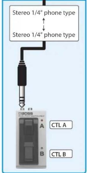
You can connect a footswitch (such as a BOSS FS-6, sold separately) or expression pedal (such as the EV-5, sold separately) to this jack. Use this when you want to switch between video using your foot.
* Use only the specified expression pedal (Roland EV-5, EV-30, BOSS FV-500L/FV-500H; sold separately). Connecting expression pedals made by third-party manufacturers may cause this unit to malfunction.
12 TALLY/GPIO connector
Use this to connect to devices that have a tally indicator feature, or to connect to devices that have a control signal input/output function.
13 AUDIO OUT (XLR, RCA) jacks
These jacks output audio. Use the jacks that are appropriate for the connected devices. For each jack, you can change the audio bus (Main, Aux 1, Aux 2, Monitor) that is assigned for output from that jack.
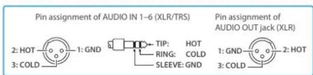
14 AUDIO IN 1-6 (XLR/TRS) jacks
Use these jacks for audio input. Connect mic or line-level analog audio equipment here.
\* About phantom power
You can supply phantom power (+48 V) from the AUDIO IN 1–6 jacks (XLR). This should be switched on for condenser mics that require phantom power.
[MENU] button → "Audio Input" → "AUDIO IN 1" – "AUDIO IN 6", and set "PHANTOM +48V" to "On".
AUDIO IN 7/L, 8/R (LINE IN) jacks
AUDIO IN 9/L, 10/R (LINE IN) jacks
Use this connector for audio input. Connect analog audio equipment such as an audio mixer here.
Connecting Bluetooth ^® Devices
Use the Bluetooth features of the VR-120HD to connect it to your Bluetooth-compatible mobile device. This lets you do the following:
- Input the audio signals from your Bluetooth audio device.
- Use dedicated app "VR-120HD Remote" to remotely control the VR-120HD from an iPad (p. 100).
* For more on connecting (pairing) with a dedicated app, see the app's Owner's Manual.
* VR-120HD Remote is planned to be updated for compatibility with this unit.
Registering a Bluetooth Audio Device (Pairing)
To connect a Bluetooth device to this unit, you must pair (register) the device with the unit.
Once you pair the device with this unit, there is no need to do it again.
* To connect a Bluetooth device that's already paired, refer to
"Connecting an Already-Paired Bluetooth Device" on this page.
* See the Owner's Manual for the Bluetooth device you want to pair for details on the necessary operations.
-
Place the Bluetooth device nearby the VR-120HD.
-
Press the [MENU] button → "System" → select "Bluetooth Pairing".
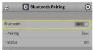
- Press the [VALUE] knob to change the setting to "ON".
The VR-120HD's Bluetooth function turns on.
- Use the [VALUE] knob to select "Pairing", and press the [VALUE] knob.
A confirmation message appears.

* If you decide to cancel, press the [EXIT] button.
- Use the [VALUE] knob to select "OK", and press the [VALUE] knob.
Pairing begins.
The following message is shown when the unit is pairing.
"Now Pairing..."
- Turn on the Bluetooth function of the Bluetooth device.
- Display the Bluetooth device screen on your Bluetooth device, and select "Roland VR-120HD Audio".
Once pairing is successful, the message on the VR-120HD changes to "Completed". - Press the [MENU] button to close the menu.
Connecting an Already-Paired Bluetooth Device
- Turn on the Bluetooth function of the Bluetooth device.
- Turn on the Bluetooth function of the VR-120HD.
The onscreen Status display on the VR-120HD changes to "Connected" when the connection is successful.
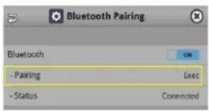
* If connection does not succeed, select "Roland VR-120HD Audio" in the Bluetooth device screen on your Bluetooth device.
MEMO
- You can also check the ✗ (Bluetooth) indicator for the connection status.
| Lit | Connected | Rapid blinking | Now pairing |
| Unlit | Bluetooth off | Blinking | Waiting for connection |
• Pair again in the following cases:
- When the pairing data has been deleted from the Bluetooth device
- When the VR-120HD has been reset to its factory-set state (p. 99).
• To remove the Bluetooth connection, deactivate Bluetooth on the VR-120HD or on your Bluetooth device.
- You can assign a function to a USER button for switching Bluetooth on/off, or for pairing (p. 90).
Connecting a Footswitch


FS-5U x 2

flowchart
graph TD
    A["Stereo 1/4" phone type"] --> B["1/4" phone type x 2"]
    B --> C["RING"]
    B --> D["TIP"]
    C --> E["FS-5U BCTL A"]
    D --> F["FS-5U BCTL A"]

FS-5U×1


FS-6


FS-7
MODE/POLARITY switch
FS-5U FS-6 FS-7


NOTE
The BOSS FS-6's A, B, and A&B jacks also act as the power switch. The power turns on when you insert a plug into the jack, and turns off when you remove the plug.
To prevent the batteries from running down, remove the plugs from the jacks when you're not using the BOSS FS-6.
Turning the Power On/Off
* Before turning the unit on/off, always be sure to turn the volume down. Even with the volume turned down, you might hear some sound when switching the unit on/off. However, this is normal and does not indicate a malfunction.
* Never turn off the power or remove the USB flash drive or SD card while the USB flash drive or SD card is being accessed.
* This unit is not designed for continuous operation over long periods of time (one month or longer). If you want to use this unit over long periods of time, cycle the power periodically.
Turning the Power On
- Make sure that all devices are powered-off.
- Turn on the [POWER] switch of the VR-120HD.

- Turn on the power of the source devices.
Turn on the power of the source devices that are connected to the VR-120HD's input connectors, such as video cameras.
- Turn on the power of the output devices.
Turn on the power of the devices that are connected to the VR-120HD's output connectors, such as projectors.
Turning the power off
- Turn off the power of the output devices first, and then the source devices.
- Turn off the [POWER] switch of the VR-120HD.
The following message appears.
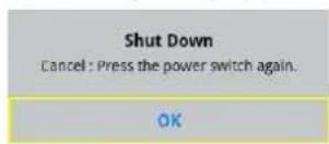
- Press the [VALUE] knob to finish shutting down.
If you wish to cancel, press the [POWER] switch again.
Operating the Menu
Here's how to access the menu, and make video/audio settings and settings for this unit.
- Press the [MENU] button to display the menu.
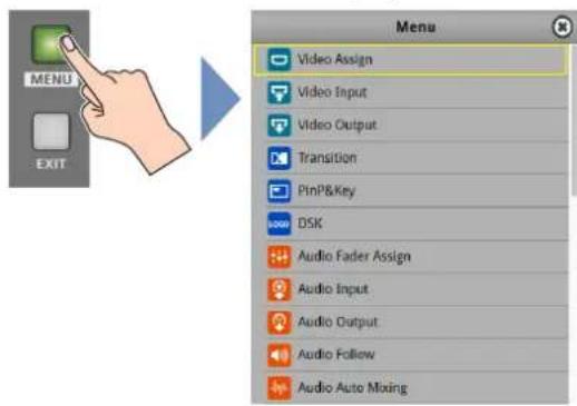
The menu is organized into functions.
- Turn the [VALUE] knob to select the menu item to edit, and press the [VALUE] knob to confirm.
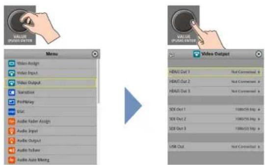
- Repeat step 2 as needed.
Press the [EXIT] button to go back up one level.
-
Turn the [VALUE] knob to change the setting value, and then press the [VALUE] knob to confirm.
-
By turning the [VALUE] knob while pressing it, you can make larger changes to the value.
-
Long-pressing the [VALUE] knob returns the current menu item you're setting to its default value.
-
Press the [MENU] button to close the menu.
MEMO
You can also operate this unit by touching the icons on the menu screen.

Operating the Setup Screen
The VR-120HD features a [SETUP] button for each section. Press the respective [SETUP] button to view the setup screen for that section, and use the touch panel to easily make important settings.
Use the menu when you want to access the detailed settings. (p. 101)

This explains how to operate the setup screens, with the MODE setup screen as an example.
- With the [INPUT SELECT] button lit up, press the MODE [SETUP] button.
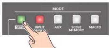
The setup screen corresponding to the current mode is shown.
- Touch the screen to change the parameter values and to switch between pages.

- When you switch between pages, different parameters are shown.
- When you change modes using a MODE button or by other means, the setup screen is shown for the respective mode.
Touch the parameter values (shown in blue) on the screen to see a list of parameter values that can be set. To change a value, scroll the list and touch the value you want to set.
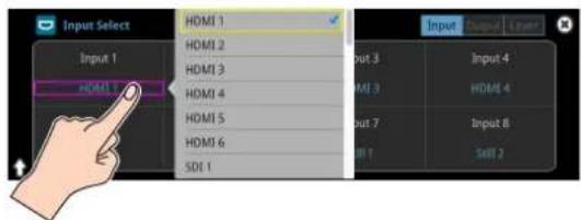
• A check mark is shown to the right of the current value.
- Press the [EXIT] button to close the list.
Press the MODE [SETUP] button to close the setup screen.
- You can also close the screen by touching the "close" icon at the top right-hand corner.
MEMO
You can use the [MENU] button, [VALUE] knob and [EXIT] button to make the settings without using the touch panel.
As with the menu, turn the [VALUE] knob to select the parameter or value to edit, and press the [VALUE] knob to confirm.
Move the yellow box (cursor) to select the parameters.
Switching the Monitor View
Aside from multi-view display, you can switch between videos to monitor such as the input video or a list of still images, according to your needs.
1. Press one of the MONITOR [1], [2], [3] or [4] buttons.
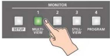
MONITOR [1] (MULTI-VIEW) button
The final output video, preview output video and the videos allocated to the cross-point [1]–[8] buttons are shown in sections of the display (multi-view).

1 PVW (preview) section
Displays the preview output video (the video to be output next).
* The fade-in/out effect (p. 34) is not reflected here.
2 PGM (program) section
Displays the final output video.
3 VIDEO SWITCHER [1]–[8] button video
Displays the video assigned to each VIDEO SWITCHER button.
The final video output and preview output video are displayed with tally frames (red and green).
![ROLAND VR-120HD - VIDEO SWITCHER [1]–[8] button video - 1](/content/2026/05/915095/images/51a6fd8cb47ad60c0f8a88e835b069bbb3d255d0f0fe3f2ad294b271f26d4565.jpg)
1 External Rec indicator
If a camera that supports the REC status function is connected, this is shown when the camera's REC button is pressed.
2 AUX/Source indicator
This displays as follows.
| Yellow PinP & KEY inset screen |
| Magenta DSK video source |
| Green AUX bus video source |
4 Setup screen
You can use the touch panel to edit the settings.
MONITOR [2] (INPUT-VIEW) button
The input video from the HDMI IN connectors and the SDI IN connectors are shown as 16 separate sections on the screen.
MONITOR [3] (STILL-VIEW) button
Shows the loaded still images in 16 separate sections on the screen.
MONITOR [4] (PROGRAM) button
Shows the final output video.
[SETUP] button
Shows the setup screen.
Audio level meter indication
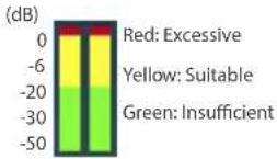
- You can set the audio level meter to show or hide.
Configure the settings of the following menu items from the [MENU] button → "SYSTEM".
| Menu item Explanation | |
| Audio Level Meter | Sets whether to show or hide the audio level meter. |
| Multi-View | |
| Input-View |
MEMO
- You can change the left-right videos that are shown in the upper part of the multi-view.
Set this by pressing the [MENU] button → "System" → "Multi-View Layout" and select "Left" or "Right".
- You can press the MONITOR [2] (INPUT-VIEW) button to change a video that's displayed.
Set this by pressing the [MENU] button → "System" → "Input-View Layout".
- You can change the monitoring videos assigned to the MONITOR [1]–[4] buttons.
To make this setting, use the [MENU] button → "System" → "Monitor Assign" → "Monitor 1" – "Monitor 4".
- Items shown on the monitor
You can individually set whether items like the tally frame, label and so on are shown or hidden.
Configure the settings of the following menu items from the [MENU] button → "System".
| Menu item Explanation | |
| Tally Frame | Tally frame |
| AUX/Source Indicator | AUX/Source indicator |
| External Rec Indicator | External Rec indicator |
| Audio Level Meter | Audio level meter |
| Preview Label | Label |
- You can change the label names that are shown in the monitor. Edit this from the [MENU] button → "System" → "Preview Label" → "Label Edit".
- For details on the cameras that support the REC status function, refer to the Roland website.
https://proav.roland.com/
About SD Card
Using an SD card lets you do the following.
•Record video or audio
- Load video or audio files
- Import/export still images or setting files
SD cards that can be used on the VR-120HD

SDXC card can be used on the VR-120HD.
Some SD card types or SD cards from some manufacturers may not properly record audio/video with the VR-120HD.
Refer to the support page on the Roland website for the latest information on compatibility.
https://roland.cm/vr-120hd

NOTE
Before you can use a commercially available SD card with the VR-120HD, you must format it as described in "Formatting an SD Card".
Inserting the SD Card
- Push the SD card all the way into the SDXC card slot until you hear a click.
NOTE
Ensure that the SD card is oriented correctly, and insert it all the way into the port. Do not forcibly push the card into place.
natural_image
Close-up of a hand pointing at a computer keyboard (no visible text or symbols)Formatting an SD Card
- Press the [MENU] button → "SD Card/USB Memory" → select "Format" and press the [VALUE] knob.
A confirmation message appears.
- Select "OK" and press the [VALUE] knob.
The SD card is now formatted.
Removing an SD Card
- Press the [MENU] button → "SD Card/USB Memory" → "SD Card" select "Eject" and press the [VALUE] knob.
- Select "OK" and press the [VALUE] knob.
Once the message "The SD Card is safe to remove" is displayed on the screen, you can safely remove the card. - Push the SD card further into the slot.
- Hold the SD card and pull it out towards you.
NOTE
- SD cards or USB flash drives that are formatted on a different device might not work normally on the VR-120HD. Be sure to format the media on the VR-120HD (SD card: exFAT format, USB flash drive: FAT32 format).
- Never turn off the power or remove the SD card or USB flash drive while the message "Processing..." is shown.
- Formatting the media erases all data saved on the SD card or USB flash drive (such as recorded video, audio and still image data). If the storage media contains important data, back the data up to your computer before you format it.
About USB Flash Drive
Using a USB flash drive lets you do the following.
- Load video or audio files
- Import/export still images or setting files
USB Flash Drives that can be used on the VR-120HD
Use a commercially available USB flash drive.
NOTE
Before you can use a commercially available USB flash drive with the VR-120HD, you must format it as described in "Formatting a USB Flash Drive".
Formatting a USB Flash Drive
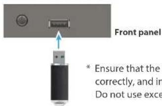
- Connect the USB flash drive to the USB HOST port.
- [MENU] button →
"SD Card/USB Memory" →
"USB MEMORY" → select "Format", and press the [VALUE] knob.
A confirmation message appears.
* If you decide to cancel, press the [EXIT] button.
- Use the [VALUE] knob to select "OK", and press the [VALUE] knob.
USB Memory is now formatted.
Removing a USB Flash Drive
- Press the [MENU] button → "SD Card/USB Memory" → "USB Memory" select "Eject" and press the [VALUE] knob.
- Select "OK" and press the [VALUE] knob.
Once the message "The USB Memory is safe to remove" is displayed on the screen, you can safely remove the card.
- Unplug the USB flash drive.
Setting the Video Input/Output Format
Here's how to specify the input/output format as appropriate for the device that's connected.
Setting the System Format
On the VR-120HD, the input/output format is determined according to the system format. You set the input/output format to match the connected equipment.
| System format | Input format (*1) Output format | ||
| HDMI IN 1-6 connectorsSDI IN 1-6 connectors | HDMI OUT 1-3 connectorsSDI OUT 1-3 connectors | USB STREAM portDIRECT STREAM port | |
| 1080p | 1080p, 1080i 1080p, | 1080i 1080p, 720p | |
| 720p | 720p 720p 720p | ||
(*1) The HDMI IN 1-6 connectors are compatible with multiple formats (when using the factory settings). You can configure a different input format for each connector, regardless of the system format. Refer to "Setting the Input Format for the HDMI IN 1-6 Connectors" on this page for details.
- [MENU] button → "System" → "Output Format" → select "System Format", and press the [VALUE] knob.

- Use the [VALUE] knob to select "1080p", or "720p", and press the [VALUE] knob.
* A change in the setting is not applied until you press the [VALUE] knob to confirm.
- Press the [MENU] button to close the menu.
Internal processing
The VR-120HD's internal processing is progressive. Interlaced input video is automatically converted to a progressive signal.
The video might appear jagged at this time, or the video in a PinP inset screen or on the multi-view might waver.
This is due to progressive conversion, and is not a malfunction.
About frame rate
Set the frame rate for the VR-120HD from the [MENU] button → "System" → Frame Rate.
* Set the frame rate for USB Out from the [MENU] button → "System" → Frame Rate "USB Out".
* Set the frame rate for streaming and for video recording from the [MENU] button → "System" → Frame Rate "Stream/Record".
Setting the Input Format for the HDMI IN 1–6 Connectors
Using the factory settings, the EDID assignment for the HDMI IN 1–6 connectors is "Internal" (so that EDID values of all formats that can be input are sent).
To specify an input format of your choice, change the setting of the EDID information being sent so that it matches the incoming video signal.
What is EDID?
EDID is data that is transmitted from the VR-120HD to the source device when the VR-120HD is connected to a source device.
EDID contains data such as the formats that can be input to the VR-120HD
(resolution, color space, color depth) and audio information.
Based on the EDID information that the source device receives, it will output the most appropriate video format to the VR-120HD.
- [MENU] button → "Video Input" → "HDMI In 1 (Scaler)" - "HDMI In 6 (Scaler)" → select "EDID" and press the [VALUE] knob.

- Use the [VALUE] knob to set the input format (the EDID information to send), and press the [VALUE] knob.
* A change in the setting is not applied until you press the [VALUE] knob to confirm.
| Value | |
| INTERNAL (EDID information for all input table formats is sent.) | |
| SXGA+ (1400 x 1050) UXGA (1600 x 1200) | |
| SVGA (800 x 600) WUXGA (1920 x 1200) | |
| XGA (1024 x 768) | 720p |
| WXGA (1280 x 800) | 1080i |
| FWXGA (1366 x 768) | 1080p |
| SXGA (1280 x 1024) | |
- Press the [MENU] button to close the menu.
Assigning Video Sources
Here's how to assign the video sources (input video, still images and video player) to the VIDEO SWITCHER [1]–[8] buttons.
- With the [INPUT SELECT] button lit up, press the MODE [SETUP] button.
The setup screen appears.
- Touch the screen to select the video source.

| Video Source Explanation | |
| HDMI 1-6 Video for HD | HMI IN connectors 1-6 |
| SDI 1-6 Video for SDI IN | connectors 1-6 |
| Still 1-16 Still images 1 | -16 |
| V.Player Video from video player | |
| Stream/Record Status 1, 2 | Status display |
| Date&Time | Date and time (analog or digital clock)The analog/digital display changes in the “System → Date&Time → Clock Display Type” setting. |
| N/A No video source | |
* You can't switch the video to a channel to which Stream/Record Status 1, 2, Date&Time or N/A is assigned. If you switch the assignment for one of the VIDEO SWITCHER [1]–[8] buttons that are now outputting, the output video switches to a black screen.
MEMO
You can import still images by using the following methods.
→ "Loading a Still Image from a Storage" (p. 27)
→ "Capturing a Still Image from Input/Output Video" (p. 28)
Adjusting Output Video
Here's how to adjust the output image appropriately for the device that's receiving the VR-120HD's output.
- [MENU] button → "Video Output" → select "HDMI Out 1-3", "SDI Out 1-3", or "USB Out" and press the [VALUE] knob.

- Use the [VALUE] knob to select a menu item shown below, and press the [VALUE] knob.
HDMI Out 1-3

| Menu item Explanation | |
| Output Status | Shows the format and an HDCP signal presence. |
| Color Space | Specifies the color space. |
| DVI-D/HDMI Signal | Specifies the type of output signal. |
| Brightness | Adjusts the brightness. |
| Contrast | Adjusts the contrast. |
| Saturation | Adjusts the saturation. |
| Red | Adjusts the red level. |
| Green | Adjusts the green level. |
| Blue | Adjusts the blue level. |
| External Rec Control | Turns the External Rec control on/off. |
SDI Out 1-3
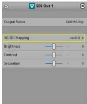
| Menu item Explanation | |
| Output Status | Shows the format and an HDCP signal presence. |
| 3G-SDI Mapping | Specifies the mapping structure of the 3G-SDI output. |
| Brightness | Adjusts the brightness. |
| Contrast | Adjusts the contrast. |
| Saturation | Adjusts the saturation. |
USB Out

| Menu item Explanation | |
| Output Status | Shows the connection status and whether or not an HDCP signal is present. |
| Output Format | Sets the output destination formats that can be selected from the livestreaming app. |
| Connection Reset | Reconnects the computer and the VR-120HD when the video is garbled or when operation is otherwise unstable. |
- Use the [VALUE] knob to edit the value of the setting, and press the [VALUE] knob.
- Press the [MENU] button to close the menu.
MEMO
You can output a test pattern, useful for adjusting the image quality of a display.
Use the [MENU] button Ó "System"Ó "Test Pattern" to specify the test pattern.
Adjusting Input Video
Here's how to adjust the quality of the input video signals.
For the HDMI IN 1-6 connectors, you can also adjust the scaling.
- [MENU] button Ó "Video Input" Ó select "HDMI In 1-6 (SCALER)", or "SDI In 1-6" and press the [VALUE] knob.

- Use the [VALUE] knob to select a menu item shown below, and press the [VALUE] knob.
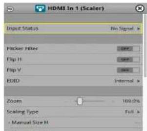
| Menu item Explanation | |
| Input Status Displays information about the incoming video. | |
| Flip H | When this is “ON”, the video is input with left and right flipped. |
| Flip V | When this is “ON”, the video is input with top and bottom flipped. |
| Brightness Adjusts the brightness. | |
| Contrast Adjusts the contrast. | |
| Saturation Adjusts the saturation. | |
| * The following parameters are only for HDMI IN 1-6 (Scaler). | |
| Flicker Filter When this is “ON”, flickering is reduced. | |
| EDID Specifies the input format (EDID) (p. 14). | |
| Zoom Adjusts the zoom ratio. | |
| Scaling Type | Specifies the scaling type. |
| Manual Size H | Adjusts the horizontal size when scaling type is set to “MANUAL”. |
| Manual Size V | Adjusts the vertical size when scaling type is set to “MANUAL”. |
| Position H | Adjusts the position in the horizontal direction. |
| Position V | Adjusts the position in the vertical direction. |
| Red | Adjusts the red level. |
| Green | Adjusts the green level. |
| Blue | Adjusts the blue level. |
- Use the [VALUE] knob to edit the value of the setting, and press the [VALUE] knob.
- Press the [MENU] button to close the menu.
Assigning Video Buses to Output Connectors
The V-120HD features seven types of video buses. You can assign the signals from each video output connector/port (HDMI OUT 1–3 connectors, SDI OUT 1–3 connectors, USB STREAM port, DIRECT STREAM port) and the video shown on this unit's display to the desired video bus.
| Video output connectors and ports | |
| HDMI Out 1-3 | HDMI OUT 1-3 connectors |
| SDI Out 1-3 | SDI OUT 1-3 connectors |
| USB Out USB STREAM port | |
| Stream/Record DIRECT STREAM port | |
| LCD Monitor This unit's display | |
| Video bus Explanation | |
| Program Final output | video |
| Sub Program | Same video as the PROGRAM busThe SUB PROGRAM bus lets you set whether to display or hide the PinP & key layers and the DSK layers, separately from the PROGRAM bus.You can edit the layer settings to output a different video from that of the PROGRAM bus. |
| Preview | Preview output video (the video to be output next)* The fade-in/out effect (p. 34) is not reflected here. |
| AUX | Video of your choice sent to the AUX bus (p. 18)This lets you allocate a separate output that is independent of the final output, such as when you want a specific input video to be a fixed output. |
| Multi-View | The final output video, preview output video and the videos allocated to the VIDEO SWITCHER [1]-[8] buttons (multi-view)MEMOYou can change the respective videos that are shown.Set this by pressing the [MENU] button → "System" → "Multi-View Layout" and select "Left" or "Right". |
| Input-View | The input video from the HDMI IN and SDI IN connectors (shown as 16 separate sections on the screen)MEMOYou can change the videos that are shown.Set this by pressing the [MENU] button → "System" → "Input-View Layout". |
| Still-View | Still images loaded into the unit (shown as 16 separate sections on the screen) |
- With the [INPUT SELECT] button lit up, press the MODE [SETUP] button.
The setup screen appears.
- Touch the page tab at the top right-hand part of the screen to select page 2 (Output).

The Output Assign screen appears.
- Touch the screen to select the video bus to assign.
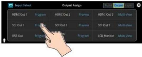
MEMO
Assigning the video buses and audio outputs
You can also assign the desired audio buses (Main bus, AUX 1 bus, AUX 2 bus, Monitor bus) for each jack, apart from the video bus (p. 61).
Selecting the Video Sent to the AUX Bus
Here's how to send the video of your choice to the AUX bus. This lets you allocate a separate output that is independent of the final output, such as when you want a specific input video to be a fixed output.
1. Press the [AUX] button.

2. Press the VIDEO SWITCHER [1]–[8] buttons to select the video signal to send to the AUX bus.

The video is switched for the output connector to which the AUX bus is assigned.
MEMO
You can also directly touch the Multi-View, Input-View or Still-View screens to select a video signal.
If you touch the screen directly to select a video, the VIDEO SWITCHER [1]–[8] buttons may not light up green in some cases.
Configuring on the setup screen
1. With the [AUX] button lit up, press the MODE [SETUP] button.
The setup screen appears.
2. Touch the screen to select the video signal to send to the AUX bus.

MEMO
- You can adjust how much audio is sent to the AUX bus.
→ "Sending Audio to the AUX Bus" (p. 61)
- Sending the same video as the final output to the AUX bus (AUX link)
You can use the AUX link function to send the same video as the final output video to the AUX bus. The video sent to the AUX bus automatically switches in tandem with the video transitions.
From the [MENU] button → "System", set the "AUX Linked PGM" to "Auto Link" or "Manual Link" (p. 150).
Inputting Copy-Protected (HDCP) Video
If you want to input HDCP-protected video from a BD player or other device, you can enable HDCP input.
* If you want to output copy-protected (HDCP) video or audio, connect a device that supports HDCP.
What's HDCP?
HDCP is copyright-protection technology that prevents unlawful copying of content by encoding the path when sending digital signals from a video playback device to a display monitor or other display equipment.
1. [MENU] button → "System" → select "HDCP", and press the [VALUE] knob.
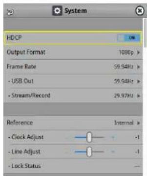
| Value Explanation | |
| ON | Copy-protected (HDCP) video can be input. HDCP is also added to the video that is output.* Video/audio from the SDI OUT connectors and the USB STREAM port are not outputted. |
| OFF Copy | -protected (HDCP) video cannot be input. |
2. Press the [MENU] button to close the menu.
Checking for HDCP-capable devices
Source devices
You can check the HDCP support status of the source device from the menu.
Use the [MENU] button → "Video Input" → "HDMI In 1-6 (Scaler)" → "Input Status" to display the HDCP status.
When inputting copy-protected (HDCP) video, "DETECT" is displayed.

Output devices
If a device that supports HDCP is connected, "HDCP" is displayed when you press the [MENU] button and select "Video Output"→ "HDMI OUT 1-3"→ "Output Status".
Specifying a Reference Clock
You can specify a clock to which operation of the VR-120HD is referenced (a reference clock).
- [MENU] button → "SYSTEM" → select "Reference", and press the [VALUE] knob.

- Use the [VALUE] knob to specify the reference clock, and press the [VALUE] knob.
| Value Explanation | |
| Internal | The VR-120HD's internal clock is used as the reference clock. |
| External | A synchronizing signal input via the REFERENCE IN connector is used as the reference clock.Black-burst (frame synchronization), bi-level, and tri-level synchronizing signals are supported. |
| SDI 1–6 | A signal input via one of the SDI IN 1–6 connectors is used as the reference clock.The VSYNC (vertical synchronizing) signal output from the VR-120HD is synchronized to the VSYNC signal input via SDI. |
When set to "External" or "SDI 1-6"
Adjust the following menu items as needed.
| Menu item Explanation | |
| Clock Adjust | This adjusts the phase horizontally.Adjust this when output is horizontally out of sync with the operation of other devices using the same clock. |
| Line Adjust | This adjusts the phase vertically.Adjust this when output is vertically out of sync with or field-shifted from the operation of other devices using the same clock. |
- Press the [MENU] button to close the menu.
Switching the Video
You can switch between the videos of the PGM bus and PST bus to specify the final output.
Setting the Operation Mode
There are two operation modes for switching between videos: "Dissolve" and "PGM/PST".
Dissolve mode (factory setting)
This mode selects the video to output and immediately outputs it to the PGM bus.
Press the [CUT] or [AUTO] button to select what happens when you switch between videos (the buttons light up green when pressed).
PGM/PST mode
In this mode, the PST video is displayed in the PVW bus, and you can check the video before outputting it to the PGM bus.
Press the VIDEO SWITCHER [1]–[8] buttons to select a PST video (the buttons light up green). The content is shown in the PVW bus.
- [MENU] button → "System" → select "Panel Operation", and press the [VALUE] knob.

- Use the [VALUE] knob to select "Dissolve", or "PGM/PST", and press the [VALUE] knob.
- Press the [MENU] button to close the menu.
Switching in the Dissolve Mode
This explains what to do when selecting "Dissolve mode" (p. 20) in the operation mode settings.
- Press the [MIX] or [WIPE] button to select the transition effect.

MIX
The two videos are mixed as the transition occurs.

WIPE
The next video moves across to replace the original video.

- Press the MODE [INPUT SELECT] button.
- Press the [CUT] or [AUTO] button.

- Press the VIDEO SWITCHER [1]–[8] buttons, and then select the video signal to output.

| Button to operate | Action taken when pressed |
| VIDEO SWITCHER [1]-[8] button | When [CUT] button is lit up green |
| The video switches instantly. | |
| When [AUTO] button is lit up green | |
| A switch (transition) effect is applied, and the video switches automatically. |
* During the transition effect, the selected VIDEO SWITCHER button blinks red, and then remains lit up red when the transition effect finishes.
MEMO
You can also directly touch the Multi-View, Input-View or Still-View screens to select a video signal.
Switching in the PGM/PST Mode
Here are the steps when selecting "PGM/PST mode" in the operation mode settings.
- Press the [MIX] or [WIPE] button to select the transition effect.

- Press the MODE [INPUT SELECT] button.
- Press a VIDEO SWITCHER [1]–[8] button to select the preview output video (the video to be output next).
You can check the preview output video in the PVW section of the multi-view.

Lit Green: Preview output video (the video to be output next)
MEMO
You can also directly touch the Multi-View, Input-View or Still-View screens to select a video signal.
- Press the [CUT] or [AUTO] button.
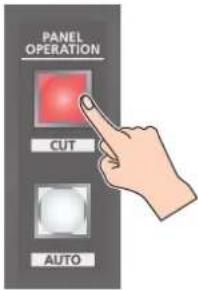
| Button to operate Action taken when pressed | |
| [CUT] button(lit up red) | The video switches instantly. |
| [AUTO] button(blink red) | A switch (transition) effect is applied, and the video switches automatically.Set the video transition time from the [MENU] button → "Transition" → "Mix" → "Mix Time" or [MENU] button → "Transition" → "Wipe" → "Wipe Time". |
MEMO
You can change the transition pattern by which the mix/wipe occurs.
→ "Changing the Mix Pattern" (p. 21)
→ "Changing the Wipe Pattern" (p. 21)
Changing the Mix Pattern
You can change the transition pattern used for a mix transition.
- With the [MIX] button lit up, press the TRANSITION [SETUP] button.
The setup screen appears.
- Touch the screen to access the settings.

| Menu item Explanation | |
| Mix Type Specifies the transition pattern for mix. | |
| Mix Time Specifies how long the transition takes. | |
* For details on the parameters, refer to "4: Transition" (p. 105).
- Press the [SETUP] button to close the screen.
Changing the Wipe Pattern
You can change the wipe transition pattern, wipe direction and other properties.
- With the [WIPE] button lit up, press the TRANSITION [SETUP] button.
The setup screen appears.
- Touch the screen to access the settings.

| Menu item Explanation | |
| Wipe Type Specifies the transition pattern for wipe. | |
| Wipe Time Specifies how long the transition takes. | |
| Direction Specifies the direction of wipe. | |
| Border Color | Specifies the color of the border added to the edge of the wipe area. |
| Border Width | Specifies the width of the border added to the edge of the wipe area. |
* For details on the parameters, refer to "4: Transition" (p. 105).
- Press the [SETUP] button to close the screen.
Splitting the Video
Here's how to composite two videos in dividing the screen into left/right or upper/lower.
Positioning a video
Left or upper: Video on the PGM bus
Right or lower: Video on the PST bus

Configuring the Screen Layout
You can configure the screen layout separately for the TRANSITION [SPLIT 1] and [SPLIT 2] buttons.
- While [SPLIT 1] or [SPLIT 2] are lit up, press the TRANSITION [SETUP] button.
The Split setup screen appears.
- Touch the screen to access the settings.

Value Explanation
| Split Type | Split VThis vertically crops the center section of the video (split left/right). |
Split HThis horizontally crops the center section of the video (split upper/lower). | |
| PGM Source | Selects the video source to display on the left or upper side. |
| PST Source | Selects the video source to display on the right or lower side. |
| PGM Center | Adjusts the position of the video that is shown in the left or upper side. |
| PST Center | Adjusts the position of the video that is shown in the right or lower side. |
| Center Position | Adjusts the position of the boundary. |
| Border Color | Specifies the color of the border. |
| Border Width | Adjusts the width of the border. |
* For details on the parameters, refer to p. 105.
MEMO
When the split setup screen is shown, you can edit the parameters such as Center Position, PGM Center and PST Center by directly dragging on the screen.

- Press the [SETUP] button to close the screen.
Displaying the Split
- Press the [SPLIT 1] or [SPLIT 2] button to turn on split compositing (the button lights up).
The SPLIT button lights up red.
- Press a VIDEO SWITCHER [1]–[8] button to select the video you want to display upper or on the left.

The video on the PGM side is selected when the SPLIT button is lit up red.
MEMO
You can also directly touch the Multi-View, Input-View or Still-View screens to select a video signal.
- Press the [SPLIT 1] or [SPLIT 2] button again.
The SPLIT button lights up green.
* The button's lit color switches between red and green each time you press the SPLIT button.
- Press a VIDEO SWITCHER [1]–[8] button to select the video you want to display lower or on the right.

The video on the PST side is selected when the SPLIT button is lit up green.
MEMO
You can also directly touch the Multi-View, Input-View or Still-View screens to select a video signal.
- To turn off the split, press the [MIX] or [WIPE] button.
Switching the Video Automatically (Auto Switching)
The video of Input 1–8 or of scene memories (p. 71) can be switched automatically (the auto switching function).
You can make operation easier by letting the video switch automatically.
About the Operation Mode
Auto switching provides six operation modes that you can select as appropriate for your situation: "input scan", "scene memory scan", "beat sync", "video follows audio", "PinP&Key scan", and "DSK scan".
Switching at a specified interval (input scan)
This automatically switches the Input 1–8 video when a specified length of time elapses. You can change the duration that each video is shown, and also switch randomly between videos.
This is convenient when you want to switch between video signals of multiple cameras, for example when live-streaming a singer-instrumentalist.
* If there is no video input, this is skipped.
Switching scene memories (scene memory scan)
This automatically recalls between scene memories 1–32. The video and audio are switched according to the settings that are saved in each scene memory.
* Scene memories in which no settings have been saved are skipped.
Switching in sync with the beat of the music (beat sync)
This detects the beat of the song, and automatically switches the video at intervals of the beat.
This lets you create video transitions that are synchronized with the music, for example when live-streaming a DJ performance or a musical performance.
Switching according to the mic volume (video follows audio)
This detects the audio that is input from a mic, and automatically switches to the specified video according to the volume.
For example, if you're streaming a talk show or a conversation, you can use this to switch between a close-up of the individual who is speaking and a wide shot of both people when neither person is speaking.
Switching between picture-in-picture (PinP) content (PinP & Key scan)
The inset screen video automatically changes after a specified length of time. You can change how long each video is shown and switch randomly between videos.
Switching between downstream keyer (DSK) content (DSK scan)
The caption video automatically changes after a specified length of time. You can change how long each video is shown and switch randomly between videos.
Turning the Auto Switching Function On/Off
MEMO
By assigning auto-switching functions to the USER buttons, you can use the buttons to turn functions on/off and configure the settings from the setup screen.
* The on/off function for auto-switching is assigned to the USER [2] button by factory default.
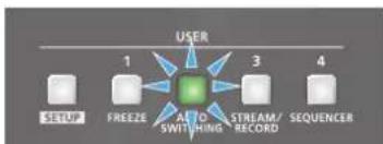
- Press the USER [2] (AUTO SWITCHING) button to turn the auto-switching function on (the button lights up).
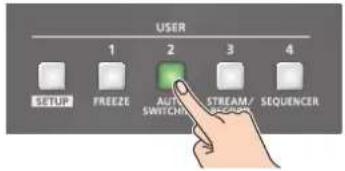
The video automatically switches according to the operating mode.
- To turn the auto-switching function off, press the USER [2] (AUTO SWITCHING) button again.
Setting the Operation Mode
- Press the USER [SETUP] button.
The User Assign screen appears.
- Touch User 2
.

The Auto Switching setup screen appears.
- Touch
to select the operating mode.

- Press the [SETUP] button to close the screen.
Input scan
- On the setup screen for the auto-switching function, touch
to select "Input Scan".

The setup screen changes accordingly.
- Touch the screen to access the settings.
| Menu item Explanation | |
| Scan Sequence | Specifies the order in which video signals are shown.Normal:Switches in the order of Input 1→8.Reverse:Switches in the order of Input 8→1.Random:Switches randomly. |
| Scan Target | Sets the video to which auto switching is applied.Video Input:Final output video and preview videoPinP & Key 1-4:PinP and key layer (inset screen) videoDSK 1-2:DSK layer (inset screen) video |
| Scan Transition Time Speci | ifies the video transition time. |
| Input 1-8 Time | Specifies the time that the video is shown. Turn this "Off" to skip. |
* For details on the parameters, refer to "20: Auto Switching" (p. 141).
- Press the [SETUP] button to close the screen.
Scene memory scan
- On the setup screen for the auto-switching function, touch
to select "Scene Memory Scan".

The setup screen changes accordingly.
- Touch the screen to access the settings.
| Menu item Explanation | |
| Scan Sequence | Specifies the order in which scene memories are switched.Normal:Switches in the order of scene memory 1→32.Reverse:Switches in the order of scene memory 32→1.Random:Switches randomly. |
| Memory 1–32 Time | Specifies the time it takes to switch to the next scene memory. Turn this “Off” to skip. |
* For details on the parameters, refer to "20: Auto Switching" (p. 141).
- Press the [SETUP] button to close the screen.
Beat sync
- On the setup screen for the auto-switching function, touch
to select "Beat Sync".

The setup screen changes accordingly.
- Touch the screen to access the settings.
| Menu item Explanation | |
| Sync Source | Specifies the input audio that synchronizes the video. |
| Scan Sequence | Specifies the order in which video signals are shown.Normal:Switches in the order of Input 1→8.Reverse:Switches in the order of Input 8→1.Random:Switches randomly. |
| Scan Transition Time | Specifies the video transition time. |
| Scan Cycle | Specifies the number of beats at which to switch to the next video. |
| Scan Target | Sets the video to which auto switching is applied.Video Input:Final output video and preview videoPinP & Key 1-4:PinP and key layer (inset screen) videoDSK 1-2:DSK layer (inset screen) video |
* For details on the parameters, refer to "20: Auto Switching" (p. 141).
- Press the [SETUP] button to close the screen.
MEMO
When an auto-switching function is assigned to a USER button and the operating mode is set to beat sync, the USER button blinks in time with the current BPM.
flowchart
graph TD
    A["USER"] --> B["1"]
    A --> C["3"]
    A --> D["4"]
    A --> E["AT TO SWITCHING"]
    A --> F["STREAM/RECORD"]
    A --> G["SEQUENCER"]
Video follows audio
- On the setup screen for the auto-switching function, touch
to select "Video Follows Audio".
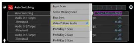
The setup screen changes accordingly.
- Touch the screen to access the settings.
| Menu item Explanation | |
| Audio In 1-9/10Target,USB In Target,Bluetooth In Target,Audio Player Target,HDMI 1-6 Target,SDI 1-6 Target,V. Player Target | Specifies the video that is output when audio is detected. |
| Threshold | Specifies the reference level at which the Video Follows Audio function operates.When audio that exceeds this threshold is detected, the video is switched. |
| Audio Mix Target | Specifies the video that is output when audio is detected in multiple mics. If this is "Off", video is switched in the order in which audio is detected. |
| Audio Silent Target | Specifies the video that is output when there is no audio input from any mic. If this is "Off", the last selected video continues to be output. |
| Audio Redetection Time | Specifies the time after the video has switched until audio detection resumes. |
| Scan Transition Time | Specifies the video transition time. |
* For details on the parameters, refer to "20: Auto Switching" (p. 141).
- Press the [SETUP] button to close the screen.
PinP&KEY scan
- On the setup screen for the auto-switching function, touch
to select "PinP&Key 1-4 Scan".
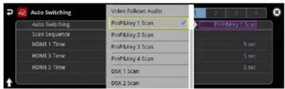
The setup screen changes accordingly.
- Touch the screen to access the settings.
| Menu item Explanation | |
| SCAN SEQUENCE | Specifies the order in which video signals are shown.Normal:Switches in the order of HDMI 1→6, SDI 1→6, STILL 1→16.Reverse:Switches in the order of STILL 16→1, SDI 6→1, HDMI 6→1.Random:Switches randomly. |
| HDMI 1–8 Time Specifies the time that the video is shown.SDI 1–8 Time Specifies the time that the video is shown. | |
| Still 1–8 Time | Specifies the time that the still image is shown. |
| V.Player Time Specifies the time that the video is shown. | |
* For details on the parameters, refer to "20: Auto Switching" (p. 141).
- Press the [SETUP] button to close the screen.
DSK scan
- On the setup screen for the auto-switching function, touch
to select "DSK 1, 2 Scan".

The setup screen changes accordingly.
- Touch the screen to access the settings.
| Menu item Explanation | |
| SCAN SEQUENCE | Specifies the order in which video signals are shown.Normal:Switches in the order of HDMI 1→6, SDI 1→6, STILL 1→16.Reverse:Switches in the order of STILL 16→1, SDI 6→1, HDMI 6→1.Random:Switches randomly. |
| HDMI 1–8 Time Specifies the time that the video is shown. | |
| SDI 1–8 Time Specifies the time that the video is shown. | |
| Still 1–8 Time | Specifies the time that the still image is shown. |
| V.Player Time Specifies the time that the video is shown. | |
* For details on the parameters, refer to "20: Auto Switching" (p. 141).
- Press the [SETUP] button to close the screen.
Loading a Still Image
You can load a still image, and output it in the same way as video (p. 28) or use it as a source for DSK compositing (p. 38). There are two ways to load a still image: you can load from storage media (either an SD card or a USB flash drive), or you can capture the image from the input video.
You can save up to sixteen still images in the unit.
* When still images are saved in the unit, startup takes longer time according to image size and the number of still images saved.
Loading a Still Image from a Storage
Here's how to load a still image from a storage into the unit.
- Save the still image in the root directory of the SD card or USB flash drive.
- Insert the SD card into the SDXC card slot.
* When using a USB flash drive, connect the USB flash drive to the USB HOST port. - [MENU] button → "Still Image" → "Load From Storage" → select "Still Image", and press the [VALUE] knob.

A " *symbol is displayed for memory where a still image is already saved.
-
Use the [VALUE] knob to select the loading destination for the still image (Still 1–16), and press the [VALUE] knob.
-
Press the [EXIT] button to return to the previous screen.
-
Use the [VALUE] knob to select "Load", and press the [VALUE] knob.
A list of the still images in the storage is shown.
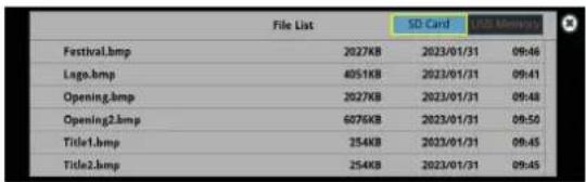
* Use the "SD Card" or "USB Memory" selector at the top right-hand corner of the screen to switch between the storage media to load from.
- Touch the filename of the still image you want to load.
A confirmation message appears.

* If you decide to cancel, press the [EXIT] button.
- Use the [VALUE] knob to select "OK", and press the [VALUE] knob.
The still image is loaded into the unit. When the operation is finished, the message "Completed" appears.
- Press the [MENU] button to close the menu.
MEMO
You can set the method of saving still images to "temporarily save". When you turn off the power, the loaded still image is deleted. From the [MENU] button → "Still Image", set "Save To Internal Storage" to "Disable", and then load the still image.
NOTE
•The still image is scaled to the output format size.
- When using a SD card or USB flash drive for the first time, you must format it using the VR-120HD (p. 13).
- Never turn off the power or remove the SD card or USB flash drive while the message "Processing..." is shown.
- Depending on the SD card or USB flash drive, it may take some time to be recognized.
Formats supported for loading
| Format | Bitmap file (.bmp), 24-bit color, uncompressed |
| PNG file (.png), 24-bit color* Alpha channel supportedJPEG file (.jpg), 24-bit color | |
| Resolution In conformity with system format (p. 14) | |
| File name | No more than 64 single-byte alphanumeric characters* The extension ".bmp", ".png", .jpg", or ".jpeg" must be added. |
Capturing a Still Image from Input/Output Video
Here's how to capture a still image from the input/output video.
- Press the [CAPTURE IMAGE] button to turn on (lit).

The Capture Image screen appears.
- Touch the screen to select the save destination memory (Still 1–16) for the still image.

* If you decide to cancel, press the [EXIT] button.
- Touch
The input video screen appears.
- Touch the screen to select the input video to capture.

* To capture the output video, set the Monitor setting to "Program" (by pressing the [Program] button), or switch to multi-view (by pressing the [Multi-View] button) to select an output video, or use Select Capture Source to select the output video.
- Touch
at the bottom of the screen.
The capture is executed. When the operation is finished, the message "Completed" appears.
- Press the [CAPTURE IMAGE] button to exit the operation.
MEMO
- You can set the method of saving still images to "temporarily save". When you turn off the power, the loaded still image is deleted. From the [MENU] button → "Still Image", set "Save To Internal Storage" to "Disable", and then load the still image.
- If you capture when HDCP (p. 18) is on, the still image that is created is handled in the same way as HDCP-protected video. It cannot be used if HDCP is off.
Outputting a Loaded Still Image
You can assign a still image to the VIDEO SWITCHER [1]–[8] buttons and output it in the same way as with video, or momentarily stop the final output to output the still image.
* When outputting a still image (.png) with an alpha channel, the alpha channel (transparency) data is ignored.
Assigning a Still Image to the VIDEO SWITCHER Buttons
A still image loaded into this unit can be assigned to the VIDEO SWITCHER [1]–[8] buttons, and output in the same way as video.
- Load a still image into this unit as described by the following procedures.
→ "Loading a Still Image from a Storage" (p. 27)
→ "Capturing a Still Image from Input/Output Video" (p. 28)
-
Assign the still image to a VIDEO SWITCHER button by following the steps in "Assigning Video Sources" (p. 16).
-
Follow the steps in "Switching the Video" (p. 20) to output the still image.
Inserting a Still Image in the Final Output
You can pause the final output, and output a still image of your choice as a cut.
Still images can be directly output without being assigned to the VIDEO SWITCHER [1]–[8] buttons.
* The same still image as the final output is also output to the preview.
Use the following methods to output still images.
Using the USER buttons
→"Assigning Functions to the USER Buttons" (p. 90)
Using a footswitch
→"Using a Footswitch" (p. 93)
Using an expression pedal
→"Using an Expression Pedal" (p. 94)
Inputting an external control signal (GPI)
→"Inputting a Control Signal" (p. 95)
MEMO
Outputting a still image with a fade-in effect
Use the [OUTPUT FADE] button to add a fade-in effect and output the still image.
Assign a still image to the AUX bus (p. 148) and edit the function for the [OUTPUT FADE] button as shown below.
Use the [MENU] button → "System" → and set Output Fade Assign "Video Fade" to "AUX".
Deleting a Still Image
Here's how to delete the still image that's saved in the unit.
- [MENU] button → "Still Image" → select "Delete Still Image", and press the [VALUE] knob.

- Use the [VALUE] knob to select the still image (All, Still 1–16) you want to delete, and press the [VALUE] knob.

A " *symbol is displayed for memory where a still image is already saved.
-
Press the [EXIT] button to return to the previous screen.
-
Select "Delete" and press the [VALUE] knob.
A confirmation message appears.
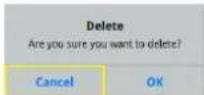
* If you decide to cancel, press the [EXIT] button.
- Use the [VALUE] knob to select "OK", and press the [VALUE] knob.
The still image is deleted. When the operation is finished, the message "Completed" appears.
- Press the [MENU] button to close the menu.
Saving a Still Image to a SD Card or USB Flash Drive
Here's how a still image captured from the input/output video (p. 28) can be saved to a storage (SD card or USB flash drive).
* The still image is saved to the "Roland/VR-120HD/still" folder.
* You can't export still images that were created while HDCP (p. 18) was set to "ON".
NOTE
- When using a SD card or USB flash drive for the first time, you must format it using the VR-120HD (p. 13).
- Never turn off the power or remove the SD card or USB flash drive while the message "Processing..." is shown.
- Depending on the SD card or USB flash drive, it may take some time to be recognized.
1. Insert the SD card into the SDXC card slot.
* When using a USB flash drive, connect the USB flash drive to the USB HOST port.
2. [MENU] button → "Still Image" → "Save To Storage" → select "Still Image", and press the [VALUE] knob.

A "★" symbol is displayed for memory where a still image is already saved.
MEMO
"(HDCP)" is indicated for still images that were created when HDCP was on.
3.
4. Use the [VALUE] knob to select the still image (Still 1–16) you want to save, and press the [VALUE] knob.
5. Press the [EXIT] button to return to the previous screen.
6. Use the [VALUE] knob to select "Save", and press the [VALUE] knob.
The still images on the storage media (in the "Still" folder) are shown as a list.

* Use the "SD Card" or "USB Memory" selector at the top right-hand corner of the screen to switch between the storage media to save.
7. Select "File Name" and press the [VALUE] knob.
This brings up the software keyboard for input.
8. Enter a file name.
* You can input up to 32 characters.
9. Touch in software keyboard.

10. Select the file type
① Use the [VALUE] knob to select "File Type", and press the [VALUE] knob.
② Use the [VALUE] knob to select "BITMAP", "PNG", or "JPEG", and press the [VALUE] knob.
11. Use the [VALUE] knob to select "Save", and press the [VALUE] knob.
A confirmation message appears.
![ROLAND VR-120HD - Use the [VALUE] knob to select "Save", and press the [VALUE] knob. - 1](/content/2026/05/915095/images/f53d0099c4b6385b71accb8f4c040431703f18e8c07baa33823782a7e96288e7.jpg)
* If you decide to cancel, press the [EXIT] button.
12. Use the [VALUE] knob to select "OK", and press the [VALUE] knob.
The still image is written to the storage.
13. Press the [MENU] button to close the menu.
MEMO
Overwriting a still image
When you touch a filename for an existing still image on the screen in step 5, the filename in the filename list is used. You can overwrite the name.
Importing a Video
Here's how to load a video from your storage media into this unit. You can play back the videos that you've loaded, and output them in the same way as with regular video signals.
- Save the video in the root directory of the SD card or USB flash drive.
- Insert the SD card into the SDXC card slot.
* When using a USB flash drive, connect the USB flash drive to the USB HOST port.
- [MENU] button → "Video Player" → select "Import", and press the [VALUE] knob.

A list of the videos in the storage is shown.

* Use the "SD Card" or "USB Memory" selector at the top right-hand corner of the screen to switch between the storage media to load from.
* Select "Root" or "Rec" in the upper left part of the screen to switch between folders from which the files are loaded.
- Touch the filename of the video you want to load.
A confirmation message appears.
* Touch the preview icon ( ● ) to play back the video.

* If you decide to cancel, press the [EXIT] button.
- Use the [VALUE] knob to select "OK", and press the [VALUE] knob.
The video is imported into the unit. When the operation is finished, the message "Completed" appears.
- Press the [MENU] button to close the menu.
NOTE
• The video is scaled to the output format size.
- When using a SD card or USB flash drive for the first time, you must format it using the VR-120HD (p. 13).
- Never turn off the power or remove the SD card or USB flash drive while the message "Processing..." is shown.
- Depending on the SD card or USB flash drive, it may take some time to be recognized.
Formats supported for importing
| Format | MP4 File (.mp4), H.264, AAC (48 kHz),Average bit rate of 20 Mbps or less |
| Resolution Maximum 1920 x 1080 pixels | |
| File name | Maximum of 64 single-byte alphanumeric characters,including the file extension |
Outputting a Loaded Video
You can assign videos to the VIDEO SWITCHER [1]–[8] buttons and output them in the same way as with video, or momentarily stop the final output to output the video.
Playing Back a Video (with the Video Player)
Use the video player to play back the videos you've loaded.
Assigning a USER button
To use the video player, you must assign the video player function to the USER buttons. This lets you play back/stop video using the assigned buttons, and operate the video from the setup screen.
The video player function is not assigned to the USER buttons by factory default.
- Assign the "Video Player" function to a USER button by following the steps in "Assigning Functions to the USER Buttons" (p. 90).
Set "Category" to "Video Player", and set "Value" to "Setup".
Video player settings
- Press the USER [SETUP] button.
The User Assign screen appears.
- Touch
for the USER button to which you assigned the video player function.
The Video Player setup screen appears.

- Touch the screen to configure the video player.
| Menu item Explanation | |
| File Import Loads the video. | |
| File Name | Shows the filename of the video that was loaded. |
| Start Time Sets the playback start point of the video. | |
| End Time Sets the playback end point of the video. | |
| Skip Forward Time | Sets how much the video fast-forwards (the amount of time) when you touch<▶▶>. |
| Skip Backward Time | Sets how much the video fast-forwards (the amount of time) when you touch<◀◀>. |
| Level Adjusts the playback volume of the video. | |
| Repeat Switches repeat playback on/off. | |
- Touch <▶>.
The video plays back according to the settings.
MEMO
You can also access the setup screen by pressing the [MENU] button and then pressing "Video Player" → "Jump to Setup".
Assigning Videos to the VIDEO SWITCHER Buttons
Here's how to assign a still image loaded into this unit to the VIDEO SWITCHER [1]–[8] buttons, and output the image in the same way as video.
- Follow the steps in "Importing a Video" (p. 31) to load the video into this unit.
-
Assign the video to a VIDEO SWITCHER button by following the steps in "Assigning Video Sources" (p. 15).
-
Follow the steps in "Switching the Video" (p. 20) to output the video.
MEMO
You can also directly touch the Multi-View, Input-View or Still-View screens to select a video signal.
Inserting a Video in the Final Output
You can pause the final output, and output a video of your choice as a cut. Video can be directly output without being assigned to the VIDEO SWITCHER [1]–[8] buttons.
* The same video as the final output is also output to the preview.
Use the following methods to output video.
Using the USER buttons
→"Assigning Functions to the USER Buttons" (p. 90)
Using a footswitch
→"Using a Footswitch" (p. 93)
Using an expression pedal
→"Using an Expression Pedal" (p. 94)
Inputting an external control signal (GPI)
→"Inputting a Control Signal" (p. 95)
NOTE
If the bitrate setting for Streaming and Recording and the bitrate of the file played on Video Player exceeds 20,000 kbps, Streaming and Recording and Video player cannot be used simultaneously.
Freezing the Input Video (Freeze)
Here's how to temporarily freeze the input video (freeze function).
You can apply transition effects during a video freeze.
MEMO
You can assign the freeze function to a USER button to turn the video on/off ("Assigning Functions to the USER Buttons" (p. 90)).
The freeze function is assigned to the USER [1] button by factory default.
Setting the Operation Mode
There are two freeze modes: the "All mode" for freezing all input video, and the "Select mode" that freezes only the input video you specify. Set the mode that matches your needs.
1. Press the USER [SETUP] button.
The User Assign screen appears.
2. Touch User 1 .

The Freeze function setup screen appears.
3. Touch to select the operating mode.

Value Explanation
All Freezes all video that is being input.
Select Freezes only the specified input video.
If "Select" is selected
4. Touch the screen to specify a source from "HDMI 1" to "SDI 6".
| Value Explanation | |
| Enable | The input video freezes. |
| Disable | The input video does not freeze. |
5. Press the [SETUP] button to close the screen.
Freezing the Input Video
1. Press the USER [1] (FREEZE) button to turn freeze on (the button lights up).

The input video freezes.
2. To turn freeze off, press the USER [1] (FREEZE) button again.
Fading-In/Out the Final Output Video
Here's how to perform a fade-out from the final output video to a black screen, or a fade-in from a black screen to the final output video.
A scene that you don't want to output as video can be changed to a black screen.
* The final output video and audio fades in/out together when using the factory default settings.
* The fade-in/out effect is applied only to the final output.
1. Press the [OUTPUT FADE] button.
![ROLAND VR-120HD - Press the [OUTPUT FADE] button. - 1](/content/2026/05/915095/images/27914af117fcd0ae45ecd2c9989c9df07ee3f93df7e6e424c3b0bce0ae15019e.jpg)
Unlit: Normal output Blinking: Now fading-in/out Lit: Faded out
The final output video fades-out to a black screen.
When fade-out is complete, the [OUTPUT FADE] button is lit.
2. To fade-in, press the [OUTPUT FADE] button once again.
The [OUTPUT FADE] button blinks, and final output begins.
When fade-in is complete, the [OUTPUT FADE] button goes dark.
MEMO
- You can use a white screen or the video from the AUX bus to add a fade-in/out effect.
To make this setting, use the [MENU] button → "System" → Output Fade Assign "Video Fade".
- To create a fade-in/out effect for the video without changing the volume, set "Audio Fade" in "Output Fade Assign" from the [MENU] button "System" to "OFF".
- To specify fade-in/out time, use the [MENU] button "System" Output Fade Assign "Time".
Compositing Video with Picture-in-Picture (PinP)
Here's how to composite an inset screen onto the background video. You can use PinP & Key 1–4 at the same time to display four inset screens.
This example shows you how to composite video using "PinP & Key 1". The operation is the same when using "PinP & Key 2-4".
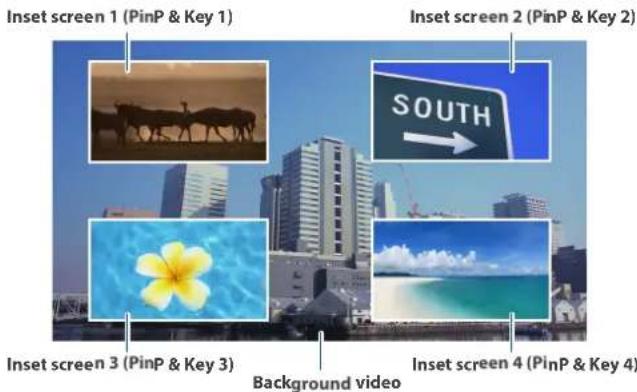
- Press the PinP & Key 1 [SETUP] button to turn it on (the button lights up).

The PinP & Key setup screen appears.
Yellow guide lines for the inset screens (PinP & Key 1) are shown in the multi-view.
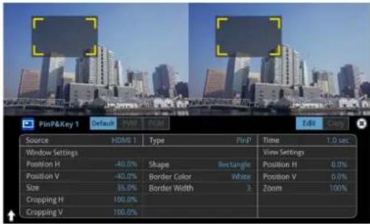
- Press a VIDEO SWITCHER [1]–[8] button to select the video you want to make the inset screen.
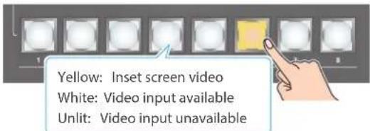
* When selecting a video that is not assigned to Input 1–8, set this in "Source" on the setup screen.
MEMO
You can also directly touch the multi-view, input-view or still-view screens to select a video signal.
- Press the PinP & KEY 1 [PVW] button to turn on the inset screen preview output (lit).
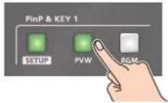
The inset screen appears in the PVW section of the multi-view, allowing you to check the inset screen's location and size.
At this stage, the final output has not yet been changed.
- Touch the setup screen to adjust the position of the inset screen.
| Window Settings Explanation | |
| Position H | Adjusts the horizontal position of the inset screen. |
| Position V Adjusts the vertical position of the inset screen. | |
| Size Adjusts the size of the inset screen. | |
MEMO
Making adjustments by touching the inset screen
You can directly drag on an inset screen to adjust its position, and you can pinch in/out to adjust its size.


- Press the PinP & KEY 1 [PGM] button to turn on PinP compositing (lit).
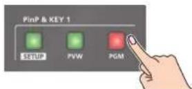
The inset screen is displayed on the final output.
- To turn off PinP compositing, press the PinP & KEY 1 [PGM] button once again.
Turning PinP/DSK composition on/off in tandem with video transitions
You can make PinP/DSK composition turn on/off in tandem with the video transitions.
From the [MENU] button → "System", set "Effects Transition Sync" to "ON". After step 4, use the [AUTO] and [CUT] buttons to switch the video. PinP composition turns on, and the composited result that is previewed is sent to final output.
MEMO
- The output video layers are structured as shown in the illustration below.

- Long-pressing the [PVW] or [PGM] button for each layer shows only the layer that is targeted for the operation while the button is pressed (this is the spot function: from the [MENU] button → "System", set "Effects Spot" to "ON").
- Set the fade-in/out time for the inset screen from the "Time" parameter on the PinP&Key setup screen.
Making Detailed Settings for the Inset Screen
You can configure the detailed inset screen settings including size, shape, border width and more from the PinP setup screen.
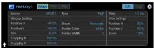
Parameter Explanation
| Source Specifies the video source of the inset screen. |
| Type Specifies the type of PinP compositing. |
| Time Specifies the video transition time. |
Window Settings Adjusts the inset screen.
| Position H Adjusts the horizontal position. |
| Position V Adjusts the vertical position. |
| Size Adjusts the size (enlarge or reduce). |
| Cropping H Adjusts the horizontal size. |
| Cropping V | Adjusts the vertical size. |
| Shape | Specifies the shape (rectangle, circle, diamond). |
| Border Color | Specifies the color of the border. |
| Border Width | Adjusts the width of the border. |
| View Settings | Adjusts the video that is shown in the inset screen. |
| Position H Adjusts the horizontal position. |
| Position V | Adjusts the vertical position. |
| Zoom | Adjusts the zoom of the video. |
* For details on the parameters, refer to "5: PinP & Key" (p. 106).
Swapping and copying settings
You can change the stacking order of the inset screens and copy the settings from other PinP & Key layers by swapping (exchanging) settings with the other PinP & Key layers.
- Touch the page tab at the top right-hand corner of the PinP setup screen and select "Copy".

- Touch the screen to access the settings.
| Value | Explanation |
| Copy From PinP & Key 1–4 | Lets you copy other PinP & Key layer settings. |
| Swap With PinP & Key 1–4 | Swaps settings with another PinP & Key layer. |
Key Compositing the Inset Screen
This process makes part of the inset screen transparent, and composites the image with the background video.
You can use luminance key with either a black or a white background, or a chroma key with either a blue or green background.
Luminance key
You can cut out text or an image by turning its black or white portion transparent, and then superimpose it on the background video.
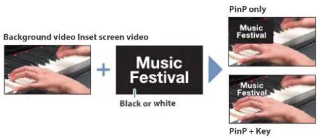
flowchart
graph LR
    A["Background video Inset screen video"] --> B["+"]
    B --> C["Music Festival"]
    C --> D["Black or white"]
    D --> E["PinP only"]
    E --> F["Music Festival"]
    F --> G["PinP + Key"]
Chroma key
You can cut out a video by turning its blue or green portion transparent, and then superimpose it on the background video.

- On the PinP setup screen, touch "Type" to select the PinP composition type.

| Value Explanation | |
| Luminance-White Key | A combination of PinP and luminance key (white). Makes the white portions of the inset screen transparent, and composites the image with the background. |
| Luminance-Black Key | A combination of PinP and luminance key (black). Makes the black portions of the inset screen transparent, and composites the image with the background. |
| Chroma Key | A combination of PinP and chroma key. Makes the specified key color portions of the inset screen transparent, and composites the image with the background. |
* For details on the parameters, refer to "5: PinP & Key" (p. 106).
- Adjust the intensity of the effect according to the selected type.
Compositing Video with Downstream Keyer (DSK)
You can further composite titles, subtitles/captions and other video on video composited using split (p. 22) or PinP (p. 35).
There are two DSK series on the VR-120HD. DSK layers are shown in front of other layers ( memo on p. 35).
About DSK Mode
There are three DSK composition modes, "Self key", "Alpha key" and "External key".
The following video compositing is available according to the DSK mode.
Self key Luminance key (p. 39)
You can cut out text or an image by turning its black or white portion transparent, and then superimpose it on the background video.

Chroma key (p. 40)
You can cut out a video by turning its blue or green portion transparent, and then superimpose it on the background video. You can select a color from the video material to set as the key color.

Alpha key (p. 42)
Use alpha channels (areas which contain transparency data) to cut out still images and place them against different background video as a composite.

External key (p. 43)
Sets the key signal (the shape to be cut out) and the fill video (the video to be composited) separately. This uses the key signal to cut out the fill video and superimpose it on the background video to create the composite.

flowchart
graph LR
    A["Background video"] --> B["Fill video source"]
    B --> C["Key source"]
    D["Music Festival"] --> E["Music Festival"]
Compositing a Caption or Image (Luminance Key)
Here's how you can cut out text or image by turning its black or white portion transparent, and then superimpose it on the background video.

Compositing using DSK
This shows how to composite an image using "DSK 1".
The steps are the same when using "DSK 2".
1. Press the DSK 1 [SETUP] button to turn on (lit).
![ROLAND VR-120HD - Press the DSK 1 [SETUP] button to turn on (lit). - 1](/content/2026/05/915095/images/383fd5de863825509b300f835169c975cab7eb0ad83244d7239eb9c9f79b4993.jpg)
The DSK setup screen appears.

2. Touch the setup screen to make the following settings.
| Parameter Explanation | |
| DSK Mode Self Key | |
| DSK Type | Luminance-White Key(Makes white portions transparent according to brightness.) |
| Luminance-Black Key(Makes black portions transparent according to brightness.) | |
3. Press a VIDEO SWITCHER [1]–[8] button to select the DSK video source.

* When selecting a video that is not assigned to Input 1–8, set this in "DSK Source" on the setup screen.
MEMO
You can also directly touch the multi-view, input-view or still-view screens to select a video signal.
4. Press the DSK 1 [PVW] button to turn on the preview output (lit).
![ROLAND VR-120HD - Press the DSK 1 [PVW] button to turn on the preview output (lit). - 1](/content/2026/05/915095/images/006dc80e6102ffe0ff6e91f3fae333b2b09eb75d46edf9105f3d7f7bc7116c9d.jpg)
A preview of the composition results is displayed in the PVW section of the multi-view.
At this stage, the final output has not yet been changed.
5. Touch the setup screen to adjust the intensity of the effect.
| Parameter Explanation | |
| DSK Settings | |
| DSK Level | Adjusts the degree of extraction (transparency) for the key. |
| DSK Gain | Adjusts the degree of edge blur (semi-transmissive region) for the key. |
| Time | Adjusts the fade-in/out time for the DSK video source. |
* For details on the parameters, refer to "6: DSK" (p. 108).
6. Press the DSK 1 [PGM] button to turn on DSK compositing (lit).

The composition results is sent to final output.
7. To turn off DSK compositing, press the DSK 1 [PGM] button once again.
Turning DSK/PinP composition on/off in tandem with video transitions
You can make DSK/PinP composition turn on/off in tandem with the video transitions.
From the [MENU] button → "System", set "Effects Transition Sync" to "ON". After step 4, use the [AUTO] and [CUT] buttons to switch the video. DSK composition turns on, and the composited result that is previewed is sent to final output.
Modifying the caption or image
You can fill-in the superimposed caption or image, or add an edge to it. Configure the following parameters on the DSK setup screen.
| Parameter Explanation | |
| Fill Settings | |
| Fill Type If this is set to "Matte", the superimposed caption or video is filled in with the color specified in "Matte Color". | |
| Matte Color | |
| Edge Settings | |
| Edge Type Specifies the type of edge. | |
| Edge Color Specifies the color of the edge. | |
| Edge Width Specifies the width of the edge. | |
* This setting is in common with chroma key ("Compositing a Subject and Background (Chroma Key)" (p. 40)).
Compositing a Subject and Background (Chroma Key)
Here's how you can cut out a video by turning its blue or green portion transparent, and then superimpose it on the background video. This lets you composite a subject that's photographed against a blue background or green background.
Compositing using DSK
This shows how to composite an image using "DSK 1".
The steps are the same when using "DSK 2".
1. Press the DSK 1 [SETUP] button to turn on (lit).
![ROLAND VR-120HD - Press the DSK 1 [SETUP] button to turn on (lit). - 1](/content/2026/05/915095/images/bab8053c04d3332c53029cd90b5dac3d980ab695ac07ed3af91aaf5eeaf68b3b.jpg)
The DSK setup screen appears.
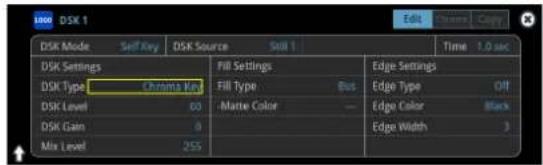
2. Touch the setup screen to make the following settings.
| Parameter Explanation | |
| DSK Mode Self Key | |
| DSK Type Chroma Key | |
| Chroma Settings (page 2) | |
| Color | Specify either “GREEN” or “BLUE” as the key color. You can also specify a color you desire as the key color (p. 41). |
3. Press a VIDEO SWITCHER [1]–[8] button to select the DSK video source.
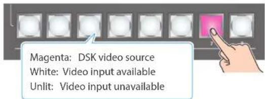
* When selecting a video that is not assigned to Input 1–8, set this in "DSK Source" on the setup screen.
MEMO
You can also directly touch the multi-view, input-view or still-view screens to select a video signal.
4. Press the DSK 1 [PVW] button to turn on the preview output (lit).
![ROLAND VR-120HD - Press the DSK 1 [PVW] button to turn on the preview output (lit). - 1](/content/2026/05/915095/images/6763c3e1a80f191c53a2898fe4b660e8d6c230e1e95d462fdc231077fbf06ab0.jpg)
A preview of the composition results is displayed in the PVW section of the multi-view.
At this stage, the final output has not yet been changed.

5. Touch the setup screen to adjust the intensity of the effect.
| Parameter Explanation | |
| DSK Settings | |
| DSK Level | Adjusts the degree of extraction (transparency) for the key. |
| DSK Gain | Adjusts the degree of edge blur (semi-transmissive region) for the key. |
| Time | Adjusts the fade-in/out time for the DSK video source. |
* For details on the parameters, refer to "6: DSK" (p. 108).
6. Press the DSK 1 [PGM] button to turn on DSK compositing (lit).

The composition results is sent to final output.
7. To turn off DSK compositing, press the DSK 1 [PGM] button once again.
Turning DSK/PinP composition on/off in tandem with video transitions
You can make DSK/PinP composition turn on/off in tandem with the video transitions.
From the [MENU] button → "System", set "Effects Transition Sync" to "ON". After step 4, use the [AUTO] and [CUT] buttons to switch the video. DSK composition turns on, and the composited result that is previewed is sent to final output.
Finely adjusting the key color
You can make fine adjustments to the key color.
Configure the following parameters on the DSK setup screen.
| Parameter Explanation | |
| Chroma Settings (page 2) | |
| Hue Width Adjusts the hue width. | |
| Hue Fine Adjusts the center position of the hue. | |
| Saturation Width Adjusts the saturation width. | |
| Saturation Fine Adjusts the center position of saturation. | |
* For details on the parameters, refer to "6: DSK" (p. 108).
Modifying the superimposed video
You can fill-in the superimposed video, or add an edge to it.
Configure the following parameters on the DSK setup screen.
| Parameter Explanation | |
| Fill Settings | |
| Fill Type | If this is set to “Matte”, the superimposed video is filled in with the color specified in “Matte Color”. |
| Matte Color | |
| Edge Settings | |
| Edge Type Specifies | the type of edge. |
| Edge Color Specifies | the color of the edge. |
| Edge Width Specifies | the width of the edge. |
* This setting is in common with luminance key ("Compositing a Caption or Image (Luminance Key)" (p. 39)).
Specifying a desired color as the key color (sampling marker)
You can specify the key color to be made transparent by sampling (detecting) a color from the video (sampling marker function).
You can also specify a key color other than green or blue.
- Touch
on page 2 of the setup screen.
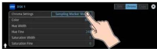
The sampling marker ( ) used to sample (detect) the key color is shown on the monitor of this unit.
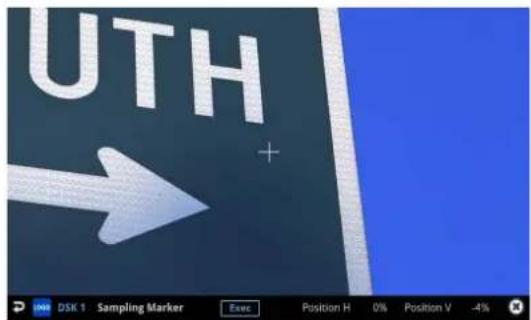
- Touch the screen to adjust the sampling marker position.
The sampling marker moves to the position you touch.
| Menu item | Explanation |
| Position H Adjusts the horizontal position. | |
| Position V | Adjusts the vertical position. |
- Touch
on the screen.
A confirmation message appears.

* If you decide to cancel, press the [EXIT] button.
- Use the [VALUE] knob to select "OK", and press the [VALUE] knob.
The key color is sampled.
The "Hue Width", "Hue Fine", "Saturation Width", and "Saturation Fine" settings are adjusted automatically.
Compositing a Still Image with Alpha Channel
Use alpha channels (areas which contain transparency data) to cut out still images and place them against different background video as a composite.
Compositing using DSK
This shows how to composite an image using "DSK 1". The steps are the same when using "DSK 2".
- Press the DSK 1 [SETUP] button to turn on (lit).

The DSK setup screen appears.
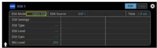
- Touch the setup screen to make the following settings.
| Parameter Explanation |
| DSK Mode Alpha key |
| DSK Source Specifies the still image with alpha channel. |
- Press a VIDEO SWITCHER [1]–[8] button to select the DSK video source.

* When selecting a video that is not assigned to Input 1–8, set this in "DSK Source" on the setup screen.
MEMO
You can also directly touch the multi-view, input-view or still-view screens to select a video signal.
- Press the DSK 1 [PVW] button to turn on the preview output (lit).

A preview of the composition results is displayed in the PVW section of the multi-view.
At this stage, the final output has not yet been changed.
Background video
Still image


Alpha channel
- Touch the setup screen to adjust the intensity of the effect.
| Parameter Explanation | |
| Mix Level Adjusts the key's overall density (output level). | |
| Time | Adjusts the fade-in/out time for the DSK video source. |
* For details on the parameters, refer to "6: DSK" (p. 108).
- Press the DSK 1 [PGM] button to turn on DSK compositing (lit).
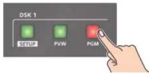
The composition results is sent to final output.
- To turn off DSK compositing, press the DSK 1 [PGM] button once again.
Turning DSK/PinP composition on/off in tandem with video transitions
You can make DSK/PinP composition turn on/off in tandem with the video transitions.
From the [MENU] button → "System", set "Effects Transition Sync" to "ON". After step 4, use the [AUTO] and [CUT] buttons to switch the video. DSK composition turns on, and the composited result that is previewed is sent to final output.
Using an External Key
This sets the key signal (the shape to be cut out) and the fill video (the video to be composited) separately. With an external key, the key signal is used to cut out the fill video and superimpose it on the background video to create the composite.
Compositing using DSK
This shows how to composite an image using "DSK 1".
The steps are the same when using "DSK 2".
1. Press the DSK 1 [SETUP] button to turn on (lit).
![ROLAND VR-120HD - Press the DSK 1 [SETUP] button to turn on (lit). - 1](/content/2026/05/915095/images/d4927392400c5886e5fe3de96d2d8da99cbc0eed6434027b1f00721614301140.jpg)
The DSK setup screen appears.
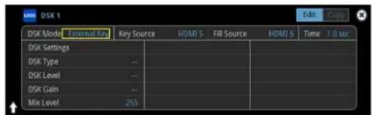
2. Touch the setup screen to make the following settings.
| Parameter Explanation |
| DSK Mode External Key |
| Key Source Specifies the video to use as the key signal. |
| Fill Source Specifies the fill video source. |
3. Press a VIDEO SWITCHER [1]–[8] button to select the fill source.
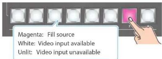
* When selecting a video that is not assigned to Input 1–8, set this in "Fill Source" on the setup screen.
MEMO
You can also directly touch the multi-view, input-view or still-view screens to select a video signal.

flowchart
graph LR
    A["Background video"] --> C["Music Festival"]
    B["Key source"] --> C
    C --> D["Music Festival"]
4. Press the DSK 1 [PVW] button to turn on the preview output (lit).
![ROLAND VR-120HD - Press the DSK 1 [PVW] button to turn on the preview output (lit). - 1](/content/2026/05/915095/images/ee672afb33a2b17347fec186a3f42e104b58f0d1556cef032d8bfeb6a5f6719c.jpg)
A preview of the composition results is displayed in the PVW section of the multi-view.
At this stage, the final output has not yet been changed.
5. Touch the setup screen to adjust the intensity of the effect.
| Parameter Explanation | |
| Mix Level Adjusts the key's overall density (output level). | |
| Time | Adjusts the fade-in/out time for the DSK video source. |
* For details on the parameters, refer to "6: DSK" (p. 108).
6. Press the DSK 1 [PGM] button to turn on DSK compositing (lit).
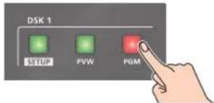
The composition results is sent to final output.
7. To turn off DSK compositing, press the DSK 1 [PGM] button once again.
Turning DSK/PinP composition on/off in tandem with video transitions
You can make DSK/PinP composition turn on/off in tandem with the video transitions.
From the [MENU] button → "System", set "Effects Transition Sync" to "ON". After step 4, use the [AUTO] and [CUT] buttons to switch the video. DSK composition turns on, and the composited result that is previewed is sent to final output.
Swapping and Copying Settings
You can change the stacking order of the DSK layers and copy other DSK layer settings by swapping (exchanging) settings with another DSK layer.
- Touch the page tab at the top right-hand corner of the DSK setup screen and select "Copy".

- Touch the screen to access the settings.
| Value Explanation | |
| Copy From DSK 1–2 | Lets you copy other DSK layer settings. |
| Swap With DSK 1–2 | Swaps settings with another DSK layer. |
Assigning Audio Sources to Audio Channels
You can assign mic audio, line input, video input (HDMI, SDI) and so on to channels 1–9/10.
This is an example of how to assign a sound source to channel 1.
- Press the [SETUP] button of the channel whose settings you want to change.
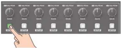
The setup screen for the channel you pressed appears.
- Touch and select an audio source to assign to the channel.

| Value Explanation | |
| Audio In 1-6 Audio from AUDIO IN 1-6 jacks | |
| Audio In 7/8-9/10 Audio from AUDIO IN 7/8-9/10 jacks | |
| USB In Audio from USB STREAM port | |
| Bluetooth In Bluetooth In audio | |
| Audio Player Audio from an audio player | |
| HDMI 1-6 (*1) Audio from HDMI IN 1-6 connectors | |
| SDI 1-6 (*1) Audio from SDI IN 1-6 connectors | |
| V.Player Audio from a video player | |
(*1) Select channels 1/2, channels 3/4, channels 5/6 or channels 7/8 from SDI or HDMI embedded audio.
- Press the lit [SETUP] button to close the setup screen.
Adjusting the Input Gain (Sensitivity)
Here's how to adjust the input gain so that the audio is at the appropriate level.
Here we explain using the channel 1 audio as an example.
NOTE
Turning the [GAIN] knobs may produce a popping noise or cause momentary audio drop-out, but this is not a malfunction.
- Position the channel 1 audio fader near the "0 dB".
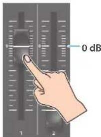
- Move the [MAIN] fader to a position near the "0 dB".

- Turn the channel 1 [GAIN] knob fully counter-clockwise, minimizing (0 dB) the input gain.

MEMO
For the Audio In 1–6 (which have analog gain circuits), you can turn this knob to adjust the analog gain. For other jacks/ports/connectors, this adjusts the digital gain instead.
- While producing the sound that will actually be input, slowly turn the [GAIN] knob clockwise to adjust the input gain.
Raise the input gain as high as possible without allowing the SIG/PEAK indicator of channel 1 to light red when the loudest sound level occurs.
NOTE
If the Audio Fader/Knob Mode is set to "Catch", the fader operations are ignored until the fader's position "catches up" to the current level. (p. 148)
* The [SETUP] button for the respective channel blinks while the fader operations are being ignored.
MEMO
Stereo link function
You can link two channels to operate them as a stereo channel. This can be set for channels 1–6. Press the [SETUP] button for the channel whose settings you want to edit, and turn "Stereo Link" ON.
* When stereo link is turned on, the settings of that channel are applied to the other channel in the stereo pair.
* When stereo link is on, the audio fader can't be used for the other channel in the stereo pair.
* When phantom power is on and you switch the stereo link setting on/off, phantom power automatically turns off.
Adjusting the mic position (pan)
The left/right positioning of the sound is called "pan". If you're using two mics to stream a performance, panning the two mics to left and right will give the sound a more spacious feel.
This can be set for channels 1–6. Press the [SETUP] button of the channel whose setting you want to change, and adjust the "Pan".
SIG/PEAK indicator
| Indicator Status | |
| Red | Volume is excessive (0 dB or higher) |
| Yellow | Volume is appropriate (-20 --1 dB). |
| Green | Volume is insufficient (-50--21 dB). |
Adjusting the digital gain
You can adjust the digital gain for all inputs. Analog gain adjusts the analog sound, and digital gain adjusts the digital sound.
When a high-level audio signal is input to the HDMI or SDI digital audio inputs, distortion may occur due to effect processing.
You can use digital gain to keep the input level down so that there is no impact on effect processing.
Adjusting the Volume Balance
Here's how to adjust the volume balance of each input and the overall volume.
1. Move the [MAIN] fader to a position near the "0 dB".

2. While monitoring the audio via speakers or headphones, adjust the volume balance for the respective inputs.
Raise the volume level of audio you want to make more prominent, for example, an emcee microphone, and lower the volume level for other audio. When no audio is input, and for audio that is unused, lower the volume level to minimum (-INF dB).

3. Use the [MAIN] fader to adjust the volume of the output.
The MAIN level meter will light yellow at the appropriate volume.
![ROLAND VR-120HD - Use the [MAIN] fader to adjust the volume of the output. - 1](/content/2026/05/915095/images/01f9455cc6efb864fdb3a19c54f2cec8feac676b78c16040ad03b346e95fa466.jpg)
| Indicator Status | |
| Red | Volume is excessive (0 dB or higher) |
| Yellow | Volume is appropriate (-20--1 dB). |
| Green | Volume is insufficient (-50--21 dB). |
NOTE
If the Audio Fader/Knob Mode is set to "Catch", the fader operations are ignored until the fader's position "catches up" to the current level. (p. 148)
* The [SETUP] button for the respective channel blinks while the fader operations are being ignored.
Adjusting the Volume Balance from the Mixer Screen
The mixer screen on this unit's display lets you adjust the various volumes while checking their values.
1. Press the [AUDIO LEVEL] button.
![ROLAND VR-120HD - Press the [AUDIO LEVEL] button. - 1](/content/2026/05/915095/images/082616c7bb3d5c4f4a94762f753a12b1fc25e3b30845c43688a7fe11c0e06c05.jpg)
The Audio Level screen appears.
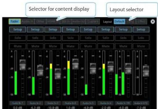
2. Drag the faders on the screen to adjust the volumes.

You can switch between content displays and layout by using the tabs at the top of the screen.
| Content displayed | Explanation |
| Fader Audio source assigned to a channel | |
| Audio In Audio from AUDIO IN 1-9/10 jacks | |
| Other | Audio from USB STREAM port, Bluetooth In, audio player and video player |
| HDMI In Audio from HDMI IN 1-6 connectors | |
| SDI In Audio from SDI IN 1-6 connectors | |
| Audio Out | Output from Main Bus, AUX 1-2 Bus, USB Out, Stream/Record |
| Custom | Custom settings. This lets you freely assign the inputs and outputs. |
| Layout Explanation | |
| Default The standard layout. | |
| Long Layout with longer fader travel. | |
| Effect | Layout which shows other parameters such as effects. |
3. Press the [AUDIO LEVEL] button to close the screen.
Applying Effects to Input Audio
You can apply effects to the input audio to adjust the character of the sound. The following table shows the effects that are available.
| Input audio | High-pass filter | Echo canceller | Anti-feedback | Noise gate | De-esser Compressor Equalizer | Voice changer | Delay Reverb | |||
| Audio In 1, 2 | √ √ √ | √ √ √ √ √ | √ √ | |||||||
| Audio In 3–6 | √ | — | — | √ √ √ | √ | — | √ | √ | ||
| Audio In 7/8–9/10 | √ | — | — | √ | — | √ | √ | — | √ | √ |
| USB In | √ | — | — | √ | — | √ | √ | — | √ | √ |
| Bluetooth In | √ | — | — | √ | — | √ | √ | — | √ | √ |
| HDMI In, SDI In | √ | — | — | √ | — | √ | √ | — | √ | √ |
| Audio Player,Video Player | √ | — | — | √ | — | √ | √ | — | √ | √ |
- Press the [SETUP] button for the channel to which you wish to apply effects.
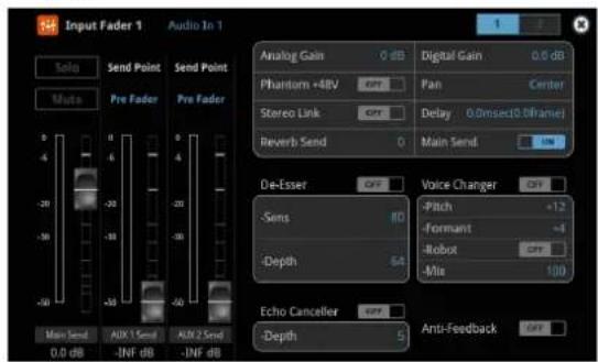
The setup screen for the channel you pressed appears.
- Touch the screen to configure the effects.

* The settings screen for the high-pass filter, compressor, equalizer and noise gate is on page 2.
* For details on the parameters, refer to "8: Audio Input" (p. 110).
- Press the lit [SETUP] button to close the setup screen.
High-pass filter
Cuts off unneeded low-band audio. The cutoff frequency is 80 Hz.
Echo canceller (p. 50)
Suppresses the voice echo that can occur when using a web conferencing system that includes a speaker and mic.
Anti-feedback (p. 50)
Suppresses audio feedback.
Noise gate
Eliminates audio that is lower than the specified threshold level. This is effective when the noise that you want to remove is separate from the audio that you want to keep, and can be used to remove hiss or other noise that is heard during periods of silence.
De-esser
Reduces sibilant noise (the sounds you hear when pronouncing "s" words and other hissing sounds).
Compressor
Audio that exceeds the specified threshold level is compressed. This reduces the difference between the maximum volume and minimum volume, making the audio more comfortable for listening.
Equalizer
This is a four-band equalizer. It lets you adjust the volume by boosting or cutting four frequency regions.
● Voice changer (p. 50)
Transforms the pitch or character of the voice.
Delay (p. 50)
Outputs audio with a delay.
Reverb (p. 51)
Adds reverberation to the sound.
Using an Effect Preset
The VR-120HD is equipped with effects that are adjusted for specific environments. These are called "effect presets".
The effect presets are created using a combination of four effects (high-pass filter, compressor, equalizer, noise gate).
Simply by selecting an effect preset, you can easily apply an effect that's appropriate for your situation.
MEMO
- To make detailed adjustments to a preset, edit the high-pass filter, compressor, equalizer and noise gate settings on the channel setup screen (page 2).
- You cannot overwrite the effect presets. Use the scene memories to save the settings for presets you've edited (p. 71).
- When you load an effect preset, each preset setting is restored to its default setting (factory defaults).
1. Touch the page tab at the top right-hand corner of the channel setup screen to select page 2.
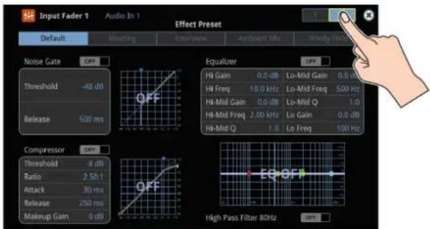
2. Select an effect preset by touching the screen.
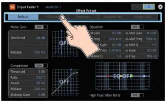
| Value Explanation | |
| Default | For line input (default setting) |
| Meeting | For meetings |
| Interview | For interviews |
| Ambient Mic | For capturing ambient sound |
| Windy Field | For capturing ambient sound in a windy area |
A confirmation message appears.
* If you decide to cancel, press the [EXIT] button.
3. Use the [VALUE] knob to select "OK", and press the [VALUE] knob.
The effect preset is loaded.
4. Configure the settings for each effect as necessary.
Touch the onscreen graphics to enlarge the settings for the effect. You can also directly drag a point on the graph onscreen to edit.
Noise gate

Compressor

● Equalizer, High-pass filter

line
| Metric | Value | | ---------------- | --------- | | Hi Gain | 2.6 dB | | Hi Freq | 6.30 kHz | | Hi-Mid Gain | -6.6 dB | | Hi-Mid Freq | 1.00 kHz | | Hi-Mid Q | 4.9 | | Lo-Mid Gain | -0.5 dB | | Lo-Mid Freq | 409 HU | | Lo-Mid Q | 1.6 | | Lo Gain | -6.8 dB | | Lo Freq | 80.0 Hz |* For details on the parameters, refer to "8: Audio Input" (p. 110).
Suppressing Echo in a Web Conference System (Echo Canceller)
In a conversation using the speaker and mic of a web conference system, an echo can occur when the other person's voice heard through the speaker is picked up by the mic and sent back to the other person.
When you use the echo canceller, the echo component is removed from the voice that is picked up by a mic connected to the VR-120HD, so that only your own voice is sent to the other party.
* This only works on the input audio from the AUDIO IN 1, 2 jacks.
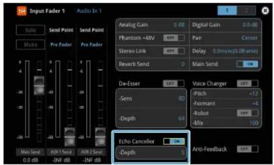
Parameter Explanation
| Echo Canceller | Turns the echo canceller on/off. |
| Depth | Adjusts the depth of the echo canceller. |
MEMO
•The echo canceller supports rooms that are approximately 20 m ^2 (215 sq ft).
- If your own voice returns to you as an echo, you'll need the other party to make echo canceller settings.
- The echo canceller works based on audio input from the USB In port.
Reducing Acoustic Feedback (Anti-Feedback)
Here's how to reduce the acoustic feedback that can occur when a mic is brought near a speaker.
* This only works on the input audio from the AUDIO IN 1, 2 jacks.

Parameter Explanation
Anti-Feedback Turns the anti-feedback on/off.
Changing the Character of a Voice (Voice Changer)
Here's how to modify the pitch or character of the voice that's input from a mic.
You can create transformations such as "from a female to a male voice", "from a male to a female voice", or "robot voice".
* This only works on the input audio from the AUDIO IN 1, 2 jacks.

Parameter Explanation
| Voice Changer Turns the voice changer on/off. | |
| Pitch | Adjusts the pitch of the voice in semitone steps.A setting of "0" is the original pitch. |
| Formant | Adjusts the character (formant) of the voice.Settings in the negative (-) direction producea more masculine vocal character, and settingsin the positive (+) direction produce a morefeminine vocal character. A setting of "0" is theoriginal voice. |
| Robot | When this is "ON", the voice is held at afixed pitch, creating a mechanical robot-likeimpression. |
| Mix | Adjusts the balance between the unprocessedvoice (0) and the voice processed by the effect(100). |
MEMO
You can assign the function to an AUDIO EFFECT button to switch the voice changer on/off (p. 90).
Correcting a Time Difference Between Video and Audio (Delay)
If there is a timing discrepancy between the video and audio, you can correct the output timing by delaying the input audio.

Parameter Explanation
Delay Adjusts the delay time of the audio.
Applying Reverb
This adds reverberation to the sound.
Adjusting how much reverb to send

Parameter Explanation
Reverb Send Adjusts the amount of audio sent to reverb.
Adjusting how much reverb is returned
* Adjust how much reverb is returned from the audio effect setup screen.
- Press the AUDIO EFFECT [SETUP] button to turn on (lit).
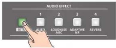
The Audio Effect Assign setup screen appears.
- Press the AUDIO EFFECT [REVERB] button to turn on (lit).

Reverb turns on.
- Touch Audio Effect 4
.
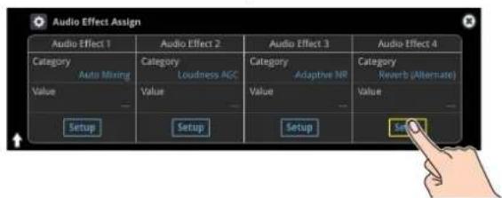
The Audio Effect setup screen appears.
- Touch the screen to access the settings.

| Parameter Explanation | |
| Level | Specifies the amount of sound that is returned from the reverb (return level). This adjusts the depth of the overall reverb. |
| Type | Specifies the reverb type.Room:Produces the natural-sounding reverberation of a room.Hall:Produces the reverberation that is typical of a performance in a concert hall. |
| Size | Specifies the size of the room. The larger the value, the longer the reverb time. |
- Press the lit [SETUP] button to close the setup screen.
Applying Effects to Output Audio
Here's how to modify the tonal character by applying effects.
The following table shows the effects that are available.
| Audio bus | Reverb Equalizer Delay | Compressor/Limiter | GEQ | Adaptive NR | Loudness AGC | ||||
| Main Bus | √ | √ | √ | √ | √ | √ | |||
| AUX Bus 1AUX Bus 2 | √ | √ | √ | √ | √ | — | — | ||
1. Press the MAIN [SETUP] button.
The Audio Output screen appears.
2. Touch for each bus.

The setup screen appears for the bus you selected.
3. Touch the screen to access the settings.
* For details on the parameters, refer to "9: Audio Output" (p. 128).
4. Press the lit [SETUP] button to close the setup screen.
Equalizer
This is a four-band equalizer. It lets you adjust the volume by boosting or cutting four frequency regions.
Delay
Outputs audio with a delay. Delaying the output lets you correct timing problems in the audio signal that is input to the output destination device.
Compressor/Limiter
Compresses audio levels that exceed the threshold you set, or limits the output level so that it does not exceed the threshold.
Graphic Equalizer
It lets you shape the character of the sound by boosting or cutting each of the 15 frequency regions into which the sound is divided.
●Adaptive Noise Reduction (p. 53)
By continuously monitoring the input audio to detect noise during periods of silence, this removes only the noise component.
● Loudness Auto Gain Control (p. 54)
The long-term average loudness is measured, and the volume is adjusted so that it is appropriate overall.
Interlinking Audio Output to Video Switching (Audio Follow)
Here's how the audio output can be automatically switched in tandem with video switching (the audio follow function).
-
[MENU] button → select "Audio Follow", and press the [VALUE] knob.
-
Use the [VALUE] knob to select the input video that uses audio follow.

- Press the [VALUE] knob to turn it "ON".
| Value | Explanation |
| ON | The audio is output only when the video is selected. The audio is automatically muted if another video is selected. |
| OFF | The audio is always output regardless of the video selection. |
- Press the [MENU] button to close the menu.
Adding an Object for Audio Follow
You can set Audio Follow to apply to the audio from the Audio In, USB In or Bluetooth In.
- [MENU] button → "Audio Follow" → and select the audio input that will be the object of Audio Follow.

- Use the [VALUE] knob to select one of "Input 1" - "Input 8".
| Value | Explanation |
| Input 1-8, HDMI 1-6, SDI 1-6, Still 1-16, V.Player | For each audio source, these settings specify the input video that will use the audio follow function. Audio is output only when the specified input video is selected. |
| Off | The audio is always output regardless of the video selection. |
- Press the [MENU] button to close the menu.
MEMO
You can synchronize the audio with the on/off state of the PinP&Key or DSK (p. 136).
Removing Noise from the Audio (Adaptive Noise Reduction / Low Frequency Cut)
You can remove noise from the input audio. Two effects are provided: "adaptive noise reduction" and "low frequency cut."
● Adaptive Noise Reduction
By continuously monitoring the input audio to detect noise during periods of silence, this removes only the noise component. Unlike conventional noise reduction that removes sound of a specified frequency, this analyzes the frequency of the noise and removes it as appropriate for the environment, resulting in a more natural sound.
* The presence or absence of voice in the input signal is determined according to the "Talking Detector" settings.
Low Frequency Cut
This divides the region below 200 Hz into four bands, and cuts unneeded low-frequency regions while continuously analyzing each band. Unlike conventional low cut, this does not weaken the sound of the low-frequency region.
Adaptive Noise Reduction
- Press the AUDIO EFFECT [SETUP] button to turn on (lit).

The Audio Effect Assign setup screen appears.
- Press the AUDIO EFFECT [ADAPTIVE NR] button to turn on (lit).

Adaptive noise reduction function turns on.
- Touch Audio Effect 3
.
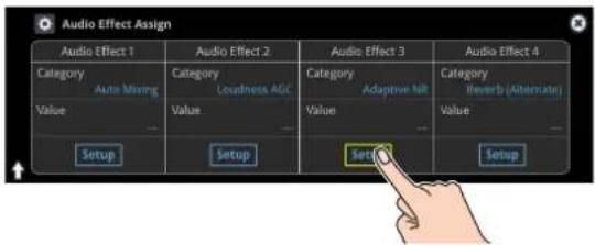
The adaptive noise reduction setup screen appears.

- Touch
to set it to "Enable".
The noise is automatically detected, and the noise is reduced.
* If you want to detect noise manually, touch Manual Measure
- Touch
to set the depth (how aggressive the noise reduction is). - If the ambient noise level is high, touch
to adjust the sensitivity.
* Increasing the value raises the sensitivity of the talking detector, making detection easier even in noisy environments.
- If you want to reset the noise-reduced result to its original state, touch
.
* For details on the menu, refer to "9: Audio Output" (p. 128).
MEMO
Using
Setting values for both the adaptive noise reduction and the loudness auto gain control are reset.
Low Frequency Cut
Configure the Low Frequency Cut on the same page of the setup screen for Adaptive Noise Reduction.

- Touch
to turn it "ON".
Low frequency cut turns on.
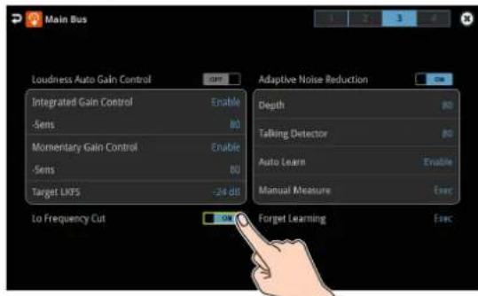
Automatically Setting a Comfortable Volume (Auto Mastering Effect)
Based on "loudness" (an index of perceptual volume), this automatically adjusts the volume appropriately for broadcast. Loudness measurement can be either long-term or short-term; these differ in the interval of time to which volume adjustment applies.
● Loudness Auto Gain Control (Loudness AGC)
The long-term average loudness is measured, and the volume is adjusted so that it is appropriate overall. Use this for audio whose dynamics you want to preserve, such as music.
Loudness Auto Gain Control (Loudness AGC)
1. Press the AUDIO EFFECT [SETUP] button to turn on (lit).

The Audio Effect Assign setup screen appears.
2. Touch Audio Effect 2 .

The loudness auto gain control setup screen appears.
3. Touch to set the target level for the output audio.
4. Press the AUDIO EFFECT [LOUDNESS AGC] button to turn on (lit).

Loudness auto gain control function turns on.
5. Touch and then use the [VALUE] knob to adjust the sensitivity, adjusting the speed at which the target level (Target LKFS) is approached.
* High settings make the loudness approach the target level rapidly, and low settings make the loudness approach the target level gradually.
6. To reset the adjusted value and return to the original state, touch .
* For details on the menu, refer to "9: Audio Output" (p. 128).
MEMO
Using
Setting values for both the adaptive noise reduction and the loudness auto gain control are reset.
Controlling the Volume Automatically (Auto Mixing)
The volume adjustments that would normally be done by the operator can be controlled automatically (auto mixing function).
Since this lets you leave the volume adjustments up to the VR-120HD, it can be used in situations where there is no dedicated operator. This is especially useful for meetings, discussions, debates, and other situations where multiple microphones are used.
- Press the AUDIO EFFECT [SETUP] button to turn on (lit).

The Audio Effect Assign setup screen appears.
- Touch Audio Effect 1
.
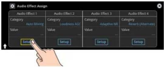
The auto mixing setup screen appears.

- Press the AUDIO EFFECT [AUTO MIXING] button to turn on (lit).
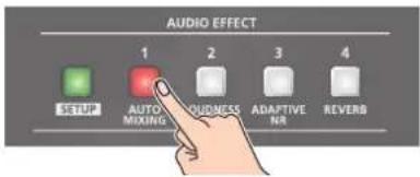
Auto mixing function turns on.
- Touch the screen to specify whether auto mixing is enabled or disabled for each audio source.

Auto mixing is applied to audio sources that are set to "Enable". For audio that does not require auto mixing, such as background music, choose "Disable".
- Touch the screen to set the priority for volume distribution (Weight).
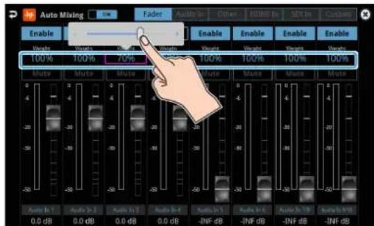
If there is audio that you want to make more prominent, such as when you want to raise the volume level of an emcee microphone, raise the weight level of that audio to emphasize it, and lower the weight level for other audio.
When air-conditioner noise or the like is a concern, specify the weight level to a low value.
-
Press the AUDIO EFFECT [SETUP] button to close the menu.
-
To turn off auto mixing function, press the AUDIO EFFECT [AUTO MIXING] button once again.
Silencing Only Specific Audio (Mute)
Here's how you can temporarily mute specific audio (the mute function).
Muting Input Audio
- Press the [MUTE] button on the channels you wish to mute.

The button lights up, and the mute function turns on.
Setting on the audio level screen
- Press the [AUDIO LEVEL] button.
The Audio Level screen appears.
-
Touch
tab. -
Touch
on the channel you wish to mute.
The mute function for the selected channel turns on.
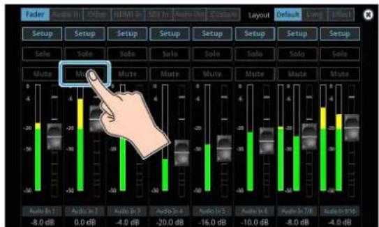

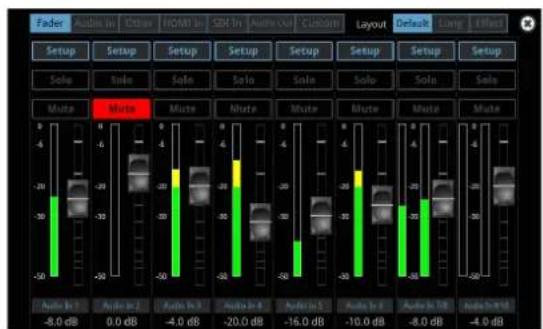
MEMO
You can also mute the channels by touching
Muting the Output Audio
This shows you how to mute the audio from the main bus, USB output, and AUX bus.
- Press the MAIN [MUTE] button.
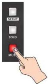
The button lights up, and the mute function turns on.
Setting on the audio level screen
- Press the [AUDIO LEVEL] button.
The Audio Level screen appears.
-
Touch
-
Touch
on the bus you wish to mute.
The mute function for the selected bus turns on.


MEMO
You can also mute the buses by touching
Checking a Specific Audio Input (Solo)
Here's how you can temporarily monitor a specific audio input via the headphones (solo function).
* The solo function applies to the headphone output. It does not affect output other than the headphones.
Soloing the Input Audio
- Press the [SOLO] button on the channels you wish to solo.

The button lights up, and the solo function turns on.
In the headphones, you hear only the audio of the channels that are set to solo.
Setting on the audio level screen
- Press the [AUDIO LEVEL] button.
The Audio Level screen appears.
-
Touch
tab. -
Touch
for the channel you wish to solo.
The solo function for the selected channel turns on.
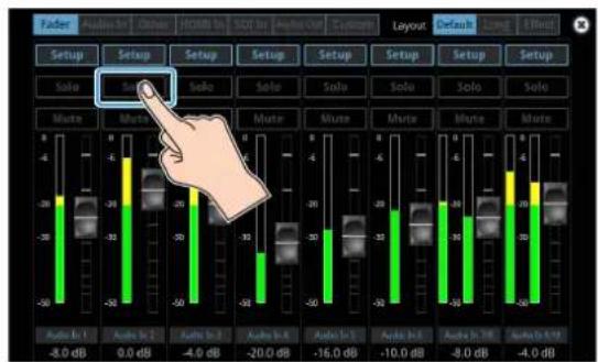


MEMO
You can also solo the channels by touching
Soloing the Output Audio
This shows you how to solo the audio from the main bus and AUX bus.
- Press the MAIN [SOLO] button.

The button lights up, and the solo function turns on.
Setting on the audio level screen
- Press the [AUDIO LEVEL] button.
The Audio Level screen appears.
-
Touch
-
Touch
for the bus you wish to solo.
The solo function for the selected bus turns on.


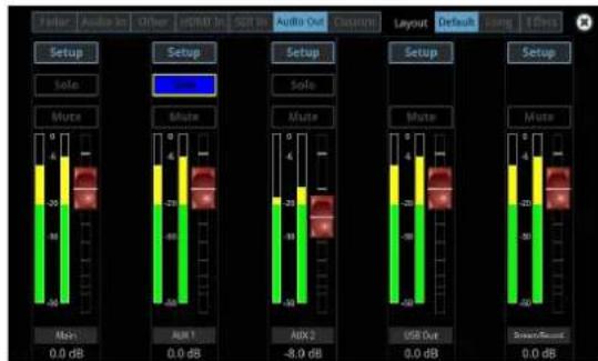
MEMO
You can also solo the buses by touching
Playing Back Audio Files (Audio Player)
Audio files that you created on your computer can be loaded (imported) into this unit as materials, and then played back by using the pads.
You can save up to 16 audio files on this unit.
Importing an Audio File
To begin, save the audio files that you created on your computer beforehand to the root directory of your SD card or USB flash drive. Here's an example of how to import an audio file into pad [1].
- Insert the SD card containing material files into the SDXC card slot.
* When using a USB flash drive, connect the USB flash drive to the USB HOST port.
- Press the AUDIO PLAYER [SETUP] button.

The Audio Player screen appears.
- Touch Player Setup
.
The Audio Player setup screen appears.
- Touch <1> in the audio clip area.

The audio clip setup screen appears.
- Touch Import
.
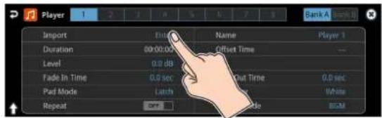
A list of audio files on your storage media is shown.

* Use the "SD Card" or "USB Memory" selector at the top right-hand corner of the screen to switch between the storage media to load from.
* Select "Root" or "Rec" in the upper left part of the screen to switch between folders from which the files are loaded.
- Touch the filename of the audio file you want to load.
* You can audition the file in headphones by touching the preview icon ( ).
- When the confirmation dialog box appears, select "OK" and press the [VALUE] knob.
The file is imported, and the data is placed in pad [1] (Audio Player 1) as an audio clip.
Supported files
| Format | WAV (Linear PCM, 48 kHz, 16 bit, stereo/ 44.1 kHz, 16 bit, stereo) |
| File name | No more than 64 single-byte alphanumeric characters * The extension "wav" must be added. |
Playing Back Audio Clips
- Set the AUDIO PLAYER [LEVEL] knob to "0dB".

- Press a pad from [1]–[8] corresponding to the position of the audio clip you want to play back.
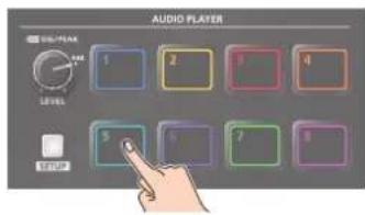
This plays back the corresponding audio clips.
- While playing back the audio clips, use the AUDIO PLAYER [LEVEL] knob to adjust the overall volume for all audio clips.
Adjust the input gain so that the SIG/PEAK indicator of the audio player doesn't light up red when the sound level is at its loudest.
MEMO
If you leave this information showing on the audio player setup screen, you can play back the audio clips while checking their information (clip name, playback time, loop, etc.).
NOTE
If the Audio Fader/Knob Mode is set to "Catch", the fader operations are ignored until the fader's position "catches up" to the current level. (p. 148)
* The [SETUP] button for the respective channel blinks while the fader operations are being ignored.
Setting an Audio Clip
- Press the AUDIO PLAYER [SETUP] button.
- Touch Player Setup
.
The Audio Player setup screen appears.
- Touch the number you want to set in the audio clip area.
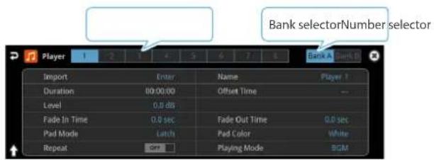
The audio clip setup screen appears.
- Touch the screen to access the settings.
| Parameter Explanation | |
| Import Imports the audio. | |
| Name Sets the name for an audio clip. | |
| Duration Shows the length of an audio clip. | |
| Offset Time Sets the playback start position of the audio clip. | |
| Level Sets the volume of the audio clip. | |
| Fade In Time Sets the fade-in time. | |
| Fade Out Time Sets the fade-out time. | |
| Pad Mode Sets what happens when the audio clip plays back. | |
| Pad Color | Specifies the color of the corresponding pad when it lights up. |
| Repeat | When this is set to “ON”, the audio clip plays back in a loop. |
| Playing Mode Specifies how the audio clip plays back. | |
* For details on the parameter, refer to "12: Audio Player" (p. 137).
Swapping, copying and deleting clips
You can copy and swap clips, and you can also initialize and delete the audio clips you no longer need.
- Press the AUDIO PLAYER [SETUP] button.
The Audio Player screen appears.
- Touch Player Setup
.
The Audio Player setup screen appears.
- Touch
, or to make the settings.
The option you touch blinks.
| Function | Operation |
| Copy | Touch the areas for the two audio clips: first the copy source and then the copy destination. |
| Swap | Touch the areas for the two audio clips you want to swap. |
| Initialize | Touch the area for the audio clip you want to initialize. |
A border appears and blinks around the area you touch.
A confirmation message appears.
- Select "OK" and press the [VALUE] knob.
Inputting the name of an audio clip
You can give each audio clip a name.
- Press the AUDIO PLAYER [SETUP] button.
The Audio Player screen appears.
- Touch Player Setup
.
The Audio Player setup screen appears.
- Touch the audio clip area.
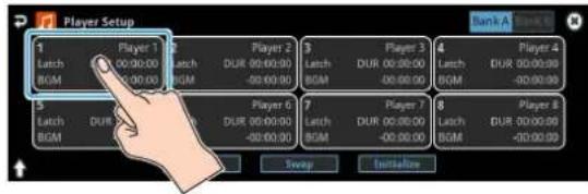
The setup screen appears.
- Touch the clip name.

This brings up the software keyboard for input.
-
Input the desired clip name.
-
Touch
in software keyboard.

Mixer Settings for the Audio Player
1. Press the AUDIO PLAYER [SETUP] button.

The Audio Player screen appears.
2. Touch Mixer Input .
The Audio Player mixer screen appears.

3. Touch the screen to configure the send amount for each bus.
On page 2, you can configure the effects as with the other audio channels.
Outputting AUX-bus Audio
The VR-120HD has four different audio buses: the Main bus, AUX 1 bus, AUX 2 bus and Monitor bus. You can assign a desired bus to each output connector or jack.
| Audio bus Explanation | |
| Main bus All | Input audio is mixed and output (main output). |
| AUX 1 busAUX 2 bus | This mixes and outputs only the input audio that is sent to the AUX bus. This allows you to output audio that is different than the master output.For example, in a live event, you might output a mix of all audio inputs, while separately outputting a mix of only specific audio inputs (the AUX bus) for recording or streaming. |
| Monitor bus | This outputs the same audio as what you hear in the headphones. Use “Monitor Level” to adjust the volume. |
Assigning the AUX Bus
- Press the MASTER OUT [SETUP] button.
The Audio Output screen appears.
- Touch Output Assign
.
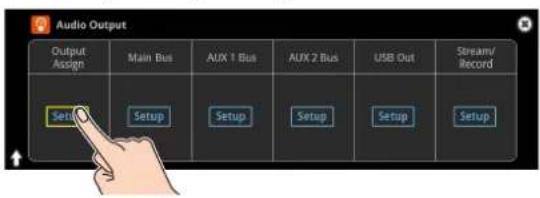
The Output Assign screen appears.

- Touch the screen to configure the bus to assign to each jack or connector.
| connector Selected bus | |
| Audio Out 1/2(XLR)-Audio Out 5/6(RCA)HDMI Out 1-3SDI Out 1-3 | Main Bus, AUX 1 Bus, AUX 2 Bus, Monitor |
| Phones Out/MonitorUSB OutStream/RecordAudio Record | Main Bus, AUX 1 Bus, AUX 2 Bus |
Sending Audio to the AUX Bus
* Use the [AUX 1] and [AUX 2] knobs to adjust the volume of audio output from the AUX bus.
- Press the [SETUP] button for the channel you wish to send to the AUX bus.
The setup screen for the channel you pressed appears.
- Touch
to set the send amount.

* For the AUX 2 bus, touch
Setting the character of the sound
You can select whether to send either the original audio or the audio processed with effects to the AUX bus.
- Press the [SETUP] button for the channel you wish to send to the AUX bus.
The setup screen for the channel you pressed appears.
- Touch
to make that setting.

| Value Explanation | |
| Dry | Sends the source audio with no effects applied. |
| Pre Fader | Sends the effect-applied audio.The send volume is constant, regardless of the volume (Input Level). |
| Post Fader | Sends the effect-applied audio.The send volume can be changed by adjusting the volume (Input Level). |
MEMO
On the setup screens for the Main Bus, AUX 1 Bus and AUX 2 Bus, you can adjust the send amounts for each channel all at once while checking each channel's status.
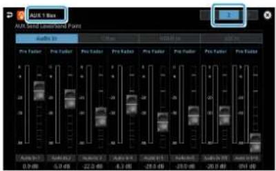
NOTE
If the Audio Fader/Knob Mode is set to "Catch", the fader operations are ignored until the fader's position "catches up" to the current level. (p. 148)
* The SIG/PEAK indicators for the [AUX 1] and [AUX 2] knobs blink while operations are being ignored.
Adding Input Audio to an HDMI or SDI Video for Output
The HDMI OUT and SDI OUT connectors support 8-channel embedded audio. You can add input audio (sound) to an HDMI or SDI video that is output.
Assigning HDMI/SDI embedded audio and sound
You can assign the input audio signal you like to channels 3–8 of HDMI or SDI embedded audio.
* These settings are common for the HDMI OUT 1–3 and SDI OUT 1–3 connectors.
| Embedded-audio Audio | |
| Channel 1 | Bus (L) assigned in Output Assign (p. 61) |
| Channel 2 | Bus (R) assigned In Output Assign (p. 61) |
| Channel 3/4 | Audio In 1/2, Audio In 3/4Audio In 5/6, Audio In 7/8, Audio In 9/10USB In, Bluetooth In, Audio Player |
| Channel 5/6 | |
| Channel 7/8 | HDMI 1-6, SDI 1-6, Video Player |
As a backup for visual or sound recording...
Digital audio is extracted from the HDMI or SDI embedded audio one channel at a time, so after visual recording or sound recording, you can edit the audio channel by channel.
For multilingual support...
Taking multilingual narration or other such audio, making it embedded audio and adding it to HDMI video or SDI video lets you later extract and use the digital audio for the required language.
- [MENU] button → "Audio Output" → select "HDMI/SDI Audio Embedded", and press the [VALUE] knob.

Assigning the audio
- Use the [VALUE] knob to select the HDMI or SDI embedded audio channel, and press the [VALUE] knob.
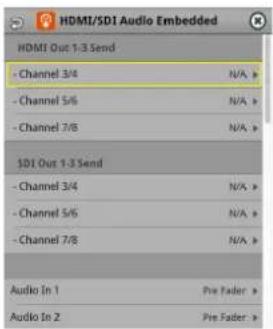
- Use the [VALUE] knob to select the input audio you wish to assign to the channel, and press the [VALUE] knob.
| Input audio Explanation | |
| Audio In 1–9/10 Audio from AUDIO IN 1–9/10 jacks | |
| USB In Audio from USB STREAM port | |
| Bluetooth In Bluetooth In audio | |
| Audio Player Audio from an audio player | |
| HDMI In 1–6 Audio from HDMI IN 1–6 connectors | |
| SDI In 1–6 Audio from SDI IN 1–6 connectors | |
| Video Player Audio from a video player | |
Setting the character of the sound
- Use the [VALUE] knob to select the input audio, and press the [VALUE] knob.

- Use the [VALUE] knob to select "Dry", "Pre Fader", or "Post Fader", and press the [VALUE] knob.
| Value | Explanation |
| Off | Audio is not sent. |
| Dry | Sends the source audio with no effects applied. |
| Pre Fader | Sends the effect-applied audio.The send volume is constant, regardless of the volume (Input Level). |
| Post Fader | Sends the effect-applied audio.The send volume can be changed by adjusting the volume (Input Level). |
- Press the [MENU] button to close the menu.
The audio including channel 3–8 embedded audio is output from the HDMI OUT 1–3 connectors or the SDI OUT 1–3 connectors.
Outputting Video/Audio to a Computer for Streaming
Here's how the video and audio mixed by the VR-120HD can be output to a connected computer. You can also input audio that's played back by the computer.
By using an internet-connected computer with streaming app, you can distribute content as a live internet stream.
In order for the audio and video from the VR-120HD to be correctly viewed on the computer, app that supports the USB video class and USB audio class must be installed on the computer.
* For the latest operating requirements, refer to the Roland website (https://proav.roland.com/).
Outputting Video and Audio to the Computer
- Using a USB 3.0 cable, connect a USB 3.0 port on the computer to the USB STREAM port on the VR-120HD.
- Turn on the power to the VR-120HD.
- Start the computer.
When communication with the computer has been established, the computer recognizes the VR-120HD as a USB video device and USB audio device. The first time that the VR-120HD is connected to the computer, the standard drivers of the operating system are installed automatically.
- Operate the VR-120HD to prepare the video and audio that you want to output to the computer.
- On your computer, verify the input from the VR-120HD.
Start app that supports the USB video class and audio class, and verify the video and audio that are being input from the VR-120HD.
MEMO
If the video is garbled or operation is otherwise unstable
Press the [MENU] button → "Video Output" → USB Out → execute "Connection Reset" to try reconnecting the computer with the VR-120HD.
Video formats
You can change the USB output video format and compression method from the livestreaming app or other app used at the output destination.
The following video formats are supported.
| USB OUT frame rate | Video formats | ||
| 59.94Hz 1080/5 | 9.94p 720/59.94p | 640 × 480/59.94p | |
| 60Hz 1080/60p | 720/60p 640 x 480 | 60p | |
| 29.97Hz 1080/2 | 9.97p 720/29.97p | 640 × 480/29.97p | |
| 30Hz 1080/30p | 720/30p 640 × 480 | 30p | |
| 50Hz 1080/50p | 720/50p 640 × 480 | 50p | |
| 25Hz 1080/25p | 720/25p 640 × 480 | 25p | |
| 23.98Hz 1080/2 | 3.98p 720/23.98p | 640 × 480/23.98p | |
| 24Hz 1080/24p | 720/24p 640 × 480 | 24p | |
* Uncompressed (YUY2) and compressed (Motion JPEG) video are supported.
Using the Loopback Function
Audio from the computer can be input to the VR-120HD via USB, mixed with other audio, and returned to the computer (the loopback function). You can add a narration to music that's played back from your computer and live-stream it, or record it using app on your computer.
Streaming Video from a Computer
Use the dedicated "Roland Live Streamer" app to stream the video and audio from the USB output of the VR-120HD with your computer.
For details on operation, refer to the Owner's Manual of "Roland Live Streamer".

You can download "Roland Live Streamer" from the Roland website.
https://proav.roland.com/
* Compressed (Motion JPEG) video is not supported.
Capturing Video on the Computer
Using dedicated "Roland Live Recorder" app, the video and audio that are output from the VR-120HD via USB can be recorded on your computer.
For details on operation, refer to the Owner's Manual of "Roland Live Recorder".

You can download "Roland Live Recorder" from the Roland website.
https://proav.roland.com/
* Compressed (Motion JPEG) video is not supported.
What to do when an HD video (1920 x 1080) output via USB changes to SD video (640 x 480)
If you are using a USB cable that doesn't conform to USB 3.0 specs or later, the video output resolution is changed to SD (640 x 480). To output video for streaming to your computer in HD (1920 x 1080), be sure to use a cable that meets the USB 3.0 specs (or later).
* If you connect via an extension cable or a USB hub, the computer might not recognize the unit.
You can check the status of the connected USB cable by following these steps.
- [MENU] button → "Video Output" → select "USB Out", and press the [VALUE] knob.
This shows the status of the USB cable that's connected.

| Output Status Status | |
| Connected (3.0) | Connected using USB 3.0. |
| Connected (2.0) | Connected using USB 2.0. |
| Not Connected | No connection. |
Streaming/Capturing Video Directly
Network Requirements

flowchart
graph TD
    A["Router"] --> B["Internet"]
    B --> C["Platform"]
    C --> D["YouTube live"]
    C --> E["Facebook Live"]
    C --> F["Twitch"]
    A --> G["LAN (DIRECT STREAM)"]
    G --> H["User Interface"]
Internet connection, including DNS server settings
- To access the Internet, the IP address, subnet mask and default gateway must be configured.
- To access the server hosting the streaming service, you must connect to the DNS (Domain Name System) server, which converts the server's domain name and IP address.
* The above settings are usually retrieved from the DHCP server and assigned.
Continuous TCP communications
To broadcast the livestream via the RTMP or RTMPS protocol over TCP, continuous communication without interruptions or restrictions between devices is required.
HTTPS connection to an Internet server
To configure the livestream for a Web app, you must have an HTTPS connection to an Internet server.
Points to Be Aware of When Livestreaming
Set the appropriate Video Bitrate (p. 137) to match the speed of your Internet connection.
Press the [MENU] button → "Stream/Record" → "Target Bitrate" → select "Video".
The video bit rate is a target bit rate that's used when compressing (encoding) video.
For complex video sequences and the like, the video may be livestreamed at a bit rate of up to around 1.5 times the value that's set.
We recommend that you test the speed of your Internet connection to ensure that a bandwidth of around twice the Video Bitrate value is available before beginning the livestream.
Starting/Stopping the Livestream, Audio or Video Recording
The livestream, audio recording and video recording on the VR-120HD start and stop all at the same time, and cannot be started or stopped separately.
* You can separately set whether to livestream, record audio or video.
Turning Livestreaming, Audio and Video Recording ON/OFF
MEMO
When the streaming/recording function is assigned to a USER button, you can set this from the setup screen.
* The streaming/recording setup screen function is assigned to the USER [3] button by factory default.
NOTE
If the bitrate setting for Streaming and Recording and the bitrate of the file played on Video Player exceeds 20,000 kbps, Streaming and Recording and Video player cannot be used simultaneously.
Turning the livestream on/off
- Press the USER [SETUP] button.
The User Assign screen appears.
- Touch User 3
.

The Record/Stream setup screen appears.

- Touch the page tab at the top right-hand part of the screen to select page 2.
- Touch either Service 1 or Service 2 to select the platform for streaming.

Select "Off" when you're not streaming.
Turning video and audio recording on/off
- Touch the page tab at the top right-hand part of the screen to select page 3.
- Touch "Video Rec" and "Audio Rec" to turn them on/off.

Livestreaming via YouTube Live
Getting ready
■Create a Google account beforehand.
■Make sure that the VR-120HD is connected to the Internet for livestreaming.
■To record audio/video, set Audio Rec and Video Rec to "On" (p. 64).
Operating this unit
- On the streaming/recording setup screen (page 2), touch either
or and select "YouTube Live".
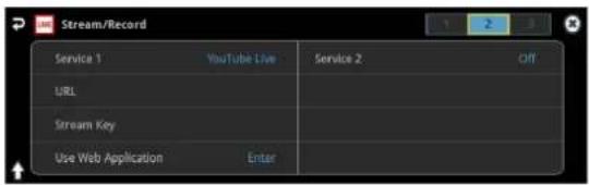
- Touch
The shortened URL and QR code for the Web app are shown.
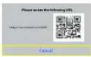
Operating your computer or smartphone
- On the Web browser of your computer or smartphone, open the link that's shown.
- Select your Google account.
- Set the following parameters.
| Item Explanation | ||
| Title | Input the title of the livestream. | |
| Description | Input the description to be shown on YouTube Live for your content. | |
| Select privacy scope | Selects the privacy settings (the scope of release) for the livestream. | |
| Public | Anyone can search for and view the content. | |
| Unlisted | The content can be accessed only via the link. | |
| Private | Only the content creator (publisher) can view the content. | |
| Select latency Preference | Selects the latency setting. | |
| normal Normal latency | ||
| low Low latency | ||
| ultralow Ultra-low latency | ||
- Click "CREATE BROADCAST AND GET STREAM KEY".
- Click "SEND TO DEVICE".
When the data transmission is finished, the message "Success" appears.
The URL and stream key are applied to the VR-120HD.
NOTE
Don't close the QR code screen until the "URL" and "Stream Key" have been applied.
- Click "OK".
- Close the page.
Operating this unit
- Select page 1 on the streaming/recording setup screen.
The parameters for stopping/starting the livestream, audio and video recording are shown in the status area.

- Touch
.
The message "Are you sure you want to start streaming?" is shown.
- Touch
.
Livestreaming starts.
If audio/video recording is turned on, the audio/video starts at the same time as the livestream.
- Touch
once more to stop streaming.
The message "Are you sure you want to stop streaming?" is shown.
- Touch
.
The livestream ends.
NOTE
- Stream keys that are acquired have an expiration date, so they need to be acquired prior to livestreaming.
- When acquiring the stream key, you can select a livestream for which the schedule has already been set by using "SELECT YOUR BROADCAST".
MEMO
You can assign streaming start/stop to the USER buttons.
On the User Assign screen, select the "Stream/Record" Category, and select "Start/Stop" for Value.
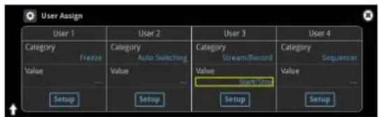
Livestreaming via Facebook Live
Getting ready
■Create a Facebook account beforehand.
■Make sure that the VR-120HD is connected to the Internet for livestreaming.
■To record audio/video, set Audio Rec and Video Rec to "On" (p. 64).
Operating this unit
- On the streaming/recording setup screen (page 2), touch either
or and select "Facebook Live".

- Touch
The shortened URL and QR code for the Web app are shown.
Operating your computer or smartphone
- On the Web browser of your computer or smartphone, open the link that's shown.
- Log in to your Facebook account.
- Set the following parameters.
| Item Explanation | ||
| Title | Input the title of the livestream. | |
| Description | Input the description to be shown on Facebook Live for your content. | |
| Selectdestination forlive-streaming | Sets where to “post” the livestream (meaning who can view the content). | |
| Timeline | The content is streamed to your personal timeline. | |
| Page | The content is streamed to a Facebook page. | |
| Group | The content is streamed to a group. | |
| Select privacy scope | Selects the privacy settings (the scope of release) for the livestream. | |
| SELF | The livestream is only visible to you. | |
| ALL FRIENDS | Only friends can view the livestream. | |
| EVERYONE Anyone can view the livestream. | ||
- Click "SUBMIT TO DEVICE!".
When the data transmission is finished, the message "Success" appears.
The URL and stream key are applied to the VR-120HD.
NOTE
Don't close the QR code screen until the "URL" and "Stream Key" have been applied.
-
Click "OK".
-
Close the page.
Operating this unit
- Select page 1 on the streaming/recording setup screen.
The parameters for stopping/starting the livestream, audio and video recording are shown in the status area.

- Touch
.
The message "Are you sure you want to start streaming?" is shown.
- Touch
.
Livestreaming starts.
If audio/video recording is turned on, the audio/video starts at the same time as the livestream.
- Touch
once more to stop streaming.
The message "Are you sure you want to stop streaming?" is shown.
- Touch
.
The livestream ends.
NOTE
Facebook stream keys that are acquired have an expiration date, so they need to be acquired prior to livestreaming.
MEMO
You can assign streaming start/stop to the USER buttons.
On the User Assign screen, select the "Stream/Record" Category, and select "Start/Stop" for Value.

Livestreaming via Twitch
Getting ready
■Create a Twitch account beforehand.
■Make sure that the VR-120HD is connected to the Internet for livestreaming.
■To record audio/video, set Audio Rec and Video Rec to "On" (p. 64).
Operating this unit
- On the streaming/recording setup screen (page 2), touch either
or and select "Twitch".

- Touch
The shortened URL and QR code for the Web app are shown.

Operating your computer or smartphone
- On the Web browser of your computer or smartphone, open the link that's shown.
- Log in to your Twitch account.
- Select the server to connect to in "Select ingest server location".
To stream your content in a more stable network environment, select a server in a region that's close to you.
* You can still livestream, regardless of which server you choose.
- Click "SUBMIT TO DEVICE!".
When the data transmission is finished, the message "Success" appears.
The URL and stream key are applied to the VR-120HD.
NOTE
Don't close the QR code screen until the "URL" and "Stream Key" have been applied.
- Click "OK".
- Close the page.
Operating this unit
- Select page 1 on the streaming/recording setup screen.
The parameters for stopping/starting the livestream, audio and video recording are shown in the status area.

- Touch
.
The message "Are you sure you want to start streaming?" is shown.
- Touch
.
Livestreaming starts.
If audio/video recording is turned on, the audio/video starts at the same time as the livestream.
- Touch
once more to stop streaming.
The message "Are you sure you want to stop streaming?" is shown.
- Touch
.
The livestream ends.
MEMO
You can assign streaming start/stop to the USER buttons.
On the User Assign screen, select the "Stream/Record" Category, and select "Start/Stop" for Value.

Streaming with Custom Settings
Getting ready
■Make sure that the VR-120HD is connected to the Internet for livestreaming.
■To record audio/video, set Audio Rec and Video Rec to "On" (p. 64).
Operating this unit
- On the streaming/recording setup screen (page 2), touch either
or and select "Custom".
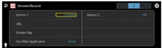
- Touch
The shortened URL and QR code for the Web app are shown.

Operating your computer or smartphone
-
On the Web browser of your computer or smartphone, open the link that's shown.
-
Input the "RTMP URL" and "Stream Key".
MEMO
You can find the "RTMP URL" and "Stream Key" on the website or other resource of the streaming platform you are going to use.
- Click "SUBMIT!".
When the data transmission is finished, the message "Success!" appears.
The URL and stream key are applied to the VR-120HD.
NOTE
Don't close the QR code screen until the "URL" and "Stream Key" have been applied.
-
Click "OK".
-
Close the page.
Operating this unit
- Select page 1 on the streaming/recording setup screen.
The parameters for stopping/starting the livestream, audio and video recording are shown in the status area.
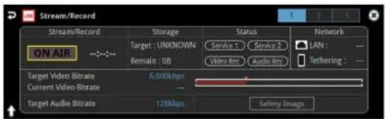
- Touch
.
The message "Are you sure you want to start streaming?" is shown.
- Touch
.
Livestreaming starts.
If audio/video recording is turned on, the audio/video starts at the same time as the livestream.
- Touch
once more to stop streaming.
The message "Are you sure you want to stop streaming?" is shown.
- Touch
.
The livestream ends.
MEMO
You can assign streaming start/stop to the USER buttons.
On the User Assign screen, select the "Stream/Record" Category, and select "Start/Stop" for Value.
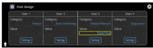
Tethering
You can connect your smartphone to this unit and use it for tethering.

iPhone:
- Use the Lightning to USB-A cable included with your iPhone to connect to the USB HOST port of the VR-120HD.
- On your iPhone, select "Settings" → "Personal Hotspot", and turn "Allow Other to Join" on.
- When you see the message, "Trust this Computer?", tap "Trust".
- If you see the message "Enter Device Passcode to Trust This Computer", enter your passcode.
- Select page 3 on the streaming/recording setup screen.

-
Touch
and select "Tethering" -
Touch
. -
Select page 1 on the streaming/recording setup screen.
Once the Network display in the status area changes from "Tethering: ---" to "Tethering: Up", you can use the mobile network connection of your iPhone.
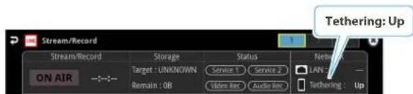
- To stop tethering, return to page 3 and touch
.
Android devices:
NOTE
The method of operation differs depending on the smartphone model. Check the owner's manual for your device for details.
- Connect the USB HOST port of the VR-120HD to your smartphone with a USB cable.
A notification is shown at the top of your smartphone screen. - On your smartphone, select "Settings" → "Network and Internet" → "Hotspot and tethering".
- Activate "USB tethering".
- Select page 3 on the streaming/recording setup screen.

-
Touch "Priority" and select "Tethering"
-
Touch
. -
Select page 1 on the streaming/recording setup screen. Once the Network display in the status area changes from "Tethering: ---" to "Tethering: Up", you can use the mobile network connection of your iPhone.
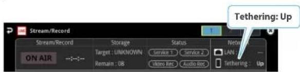
- To stop tethering, return to page 3 and touch
.
MEMO
You can also make the tethering start/stop from the menu. [MENU] button → "Network" → select "Start Tethering" or "Stop Tethering", and then press the [VALUE] knob.
Avoiding Sporadic Issues When Livestreaming (Safety Delay)
The VR-120HD comes with a built-in "safety delay" function that helps you to avoid unexpected troubles during livestreaming.
You can set the video and audio buffer (streaming delay time: "Stream Delay") for the safety delay function.
If an accidental issue occurs within the streaming delay time, you can control the "switch to still image" and "mute audio" functions with the press of a button, which prevents undesirable content from being streamed.
The safety delay function thus helps you to feel more at ease when livestreaming content, especially in situations like live events where there is no script or guide.

flowchart
graph TD
    A["Accident"] --> B["Stream Delay"]
    B --> C["Safety Image"]
- The streaming delay time can be set in five-second intervals, to a maximum of 60 seconds.
- This unit switches to the still image you imported as the "safety image".
- The unit switches to the safety image only during livestreaming. You can only check the switch to the safety image by looking at the livestreamed video. The image shown on this unit's display or the video outputted via the HDMI OUT connector doesn't switch to the safety image.
- Use this function by assigning the USER buttons to switch to the still image and to mute the audio.
Setting the Streaming Delay Time
- Select page 3 on the streaming/recording setup screen.

- Touch
to configure the setting.
Value
Off, 5 sec–60 sec (five-second intervals)
- Press the [MENU] button to close the menu.
Using the safety delay function
- Select page 1 on the streaming/recording setup screen.
- Touch
. - Touch
.
Livestreaming starts.
- Touch
at the lower right corner of the screen.

The streaming video switches to a still image, and the streaming audio is muted.
Assigning safety delay to a USER button
You can assign the safety delay function to a USER button. This example shows how to assign the safety delay function to the USER [3] button.
- Press the USER [SETUP] button.
The User Assign screen appears.
- For User 3, set the Category to "Stream/Record", and the Value to "Safety Image".

| Value Explanation | |
| Safety Image | The safety delay function switches the streaming video to a still image and mutes the streaming audio. |
- Press the [SETUP] button to close the screen.
Saving/Recalling Settings (Scene Memory)
You can save the current settings, including the video/audio settings and the state of the operating panel, in scene memory and recall those settings for use when necessary.
The VR-120HD is provided with 32 scene memories.
* The demo data in this unit includes some scene memories by factory default.
About the Last Memory function
The VR-120HD has a built-in Last Memory feature. Last Memory is a feature that saves the state of the unit that is in effect immediately before power-down, and automatically restores the state at the next startup. The Last Memory feature is enabled by default.
If you want the unit to recall a scene memory when it starts up, press the [MENU] button → "Scene Memory" → "Start Up" to specify the scene memory number.
Saving to a Scene Memory
Only for scene memories 1–8
- Press the [SCENE MEMORY] button.

- Long-press the VIDEO SWITCHER button for the number where you want to save the settings.

All VIDEO SWITCHER buttons briefly light up blue, and the current settings are saved in the selected scene memory.
Scene memory 1–32
- With the [SCENE MEMORY] button lit up, press the MODE [SETUP] button.
The Scene Memory setup screen appears.

- Touch
.
The "Save" text blinks.
- Touch the area of the scene memory number where you want to save.

A confirmation message appears.
- Select "OK" and press the [VALUE] knob.
This saves the current settings to the selected scene memory.
MEMO
- About scene memories 9–32
You can use the buttons to save or recall scene memories 9–32. Press the [MENU] button and select "Scene Memory" → "Button Assign" to set the memory to recall for each VIDEO SWITCHER button.
- You can prohibit settings from being saved or initialized (p. 72) to protect the scene memories.
Use the [MENU] button → "Scene Memory" → and set "Memory Protect" to "ON".
- Since settings related to the system, network and so on are common to the entire unit, they are not saved in a memory.
- About the demo data
Once you perform a factory reset (p. 99), any demo data you have edited or deleted is restored to its factory default settings.
Recalling a Scene Memory
Only for scene memories 1–8
- Press the [SCENE MEMORY] button.

- Press the VIDEO SWITCHER button for the number whose setting you want to recall.

The settings are recalled.
Scene memory 1–32
- With the [SCENE MEMORY] button lit up, press the MODE [SETUP] button.
The Scene Memory setup screen appears.
- Touch the area of the scene memory number whose settings you wish to recall.

The settings are recalled.
MEMO
- You can choose not to recall a certain setting when recalling a scene memory.
For each item selected using the [MENU] button →
"Scene Memory" → "Load Parameter", you can set whether to recall that setting.
- You can apply video transition effects, make an inset screen fade in and so on when you recall a scene memory.
Configure the settings of the following menu items from the [MENU] button → "Scene Memory".
| Menu Item Explanation | |
| Fade Time | Sets how long the transition to the next video takes when recalling a scene memory.* The time you set is used for the parameters below. |
| Mix/Wipe | When this is “ON”, the transition effect is applied when the scene memory is recalled. |
| PinP & Key 1-4 | When this is “ON”, the inset screen fades in when you recall a scene memory that includes a PinP composite. |
| DSK 1, 2 | When this is “ON”, the superimposed caption and video fades in when you recall a scene memory that includes a DSK composite. |
Initializing a Scene Memory
Here's how you can initialize the settings of a specific preset memory.
- With the [SCENE MEMORY] button lit up, press the MODE [SETUP] button.
The Scene Memory setup screen appears.
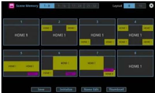
- Touch
.
The "Initialize" text blinks.
- Touch the area of the scene memory number that you want to initialize.
A confirmation message appears.
* If you decide to cancel, press the [EXIT] button.
- Select "OK" and press the [VALUE] knob.
The scene memory is initialized.
Renaming a Scene Memory
Here's how to rename a preset memory.
- With the [SCENE MEMORY] button lit up, press the MODE [SETUP] button.
The Scene Memory setup screen appears.
- Touch
.
The "Name Edit" text blinks.
- Touch the area of the scene memory number whose name you wish to edit.
This brings up the software keyboard for input.
- Input the scene memory name.
* You can input up to 8 characters.
- Touch
in software keyboard.
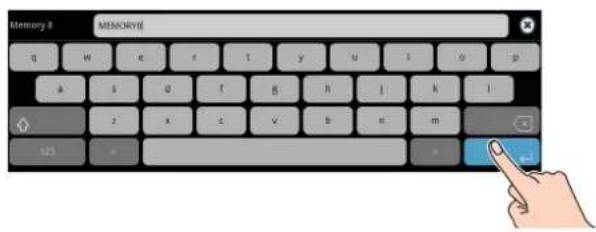
- Touch
.
The "Name Edit" text goes back to being lit up.
Changing the Thumbnail Position
You can change the position of the thumbnail used for checking the video/image content, shown on the scene memory setup screen.
1. With the [SCENE MEMORY] button lit up, press the MODE [SETUP] button.
The Scene Memory setup screen appears.

2. Touch .
The "Thumbnail" text blinks.
3. Touch the area of the scene memory number that you want to change.

This shows the thumbnail layout screen.
4. Touch the screen to access the settings.
5. Press the [EXIT] button.
Saving Scene Memories to an SD Card or USB Flash Drive
You can group together the scene memories (1–32) into a single file (.VR120SCENE) and save it to a storage (SD card, USB flash drive,) connected to the VR-120HD. You can access the saved scene memory file on the storage and load it into the unit for use when needed.
* The scene memory file is saved to and recalled from the "Roland/VR-120HD/scene_memory" folder.
NOTE
- When using a SD card or USB flash drive for the first time, you must format it using the VR-120HD (p. 13).
- Never turn off the power or remove the SD card or USB flash drive while the message "Processing..." is shown.
- Depending on the SD card or USB flash drive, it may take some time to be recognized.
Saving a new file
1. Insert the SD card into the SDXC card slot.
* When using a USB flash drive, connect the USB flash drive to the USB HOST port.
2. [MENU] button → "Scene Memory" → select "Save To Storage", and press the [VALUE] knob.

The scene memory files in the storage are listed.

* Use the "SD Card" or "USB Memory" selector at the top right-hand corner of the screen to switch between the storage media to load from.
3. Select "File Name" and press the [VALUE] knob.
This brings up the software keyboard for input.
4. Input the scene memory file name.
* You can input up to 32 characters.
5. Touch in software keyboard.
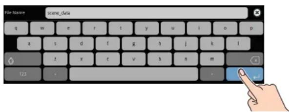
- Use the [VALUE] knob to select "Save", and then press the [VALUE] knob.
A confirmation message appears.
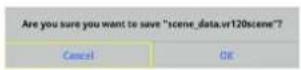
* If you decide to cancel, press the [EXIT] button.
- Use the [VALUE] knob to select "OK", and then press the [VALUE] knob.
The scene memory file (.VR120SCENE) is saved to the storage. When the operation is finished, the message "Completed" appears.
- Press the [MENU] button to close the menu.
Overwrite-saving
- Insert the SD card into the SDXC card slot.
* When using a USB flash drive, connect the USB flash drive to the USB HOST port.
- [MENU] button → "Scene Memory" → select "Save To Storage", and press the [VALUE] knob.

The scene memory files in the storage are listed.
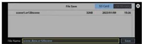
* Use the "SD Card" or "USB Memory" selector at the top right-hand corner of the screen to switch between the storage media to load from.
- Touch the scene memory file that you want to overwrite.
The filename shown in the list of filenames is used.
- Use the [VALUE] knob to select "Save", and then press the [VALUE] knob.
A confirmation message appears.
* If you decide to cancel, press the [EXIT] button.
- Use the [VALUE] knob to select "OK", and then press the [VALUE] knob.
The scene memory file is overwritten. When the operation is finished, the message "Completed" appears.
- Press the [MENU] button to close the menu.
Loading
Here's how to load the scene memory settings that are saved on a storage. Loading the settings overwrites the current settings for the scene memories.
- Insert the SD card into the SDXC card slot.
* When using a USB flash drive, connect the USB flash drive to the USB HOST port.
- [MENU] button → "Scene Memory" → select "Load From Storage", and press the [VALUE] knob.

The scene memory files in the storage are listed.

* Use the "SD Card" or "USB Memory" selector at the top right-hand corner of the screen to switch between the storage media to load from.
- Touch the scene memory file that you want to recall.
A confirmation message appears.

* If you decide to cancel, press the [EXIT] button.
- Use the [VALUE] knob to select "OK", and then press the [VALUE] knob.
The scene memory settings are loaded. When the operation is finished, the message "Completed" appears.
- Press the [MENU] button to close the menu.
Recording Multiple Operations to Automatically Execute (Macros)
This feature lets you record multiple operations and then automatically execute them (as a macro function). You only need to record the macro operation beforehand and then select the macro to perform the series of operations you recorded. This function is useful for executing exactly the same operations, even when a different operator is using the unit.
You can create up to 100 macros.
Recording a Macro
A single macro can contain up to 10 different operations. You can include a macro within another macro, to make a single macro execute a more complicated set of functions.
* The demo macro data in this unit that's available by factory default includes some recorded operations.
1. Press the [MACRO] button.
![ROLAND VR-120HD - Press the [MACRO] button. - 1](/content/2026/05/915095/images/bdd5107364d7b9d7a542c16b9df208b8cf108957409e31cef11e51c877fb60f3.jpg)
2. Press the MODE [SETUP] button.
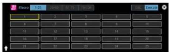
The Macro setup screen appears.
3. Touch .

The Macro edit screen appears.

4. Touch the screen to select a macro to edit.
This shows the list of operations recorded in the macro.
5. Touch .

The function edit menu appears.
6. Touch to select the operation to record to the macro.
* See "Editing a macro" (p. 76) for details on which operations you can record to a macro.
7. Touch the screen to configure the related parameters.
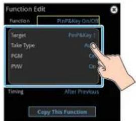
8. Touch to set the timing used to execute the operation.
| Value Explanation | |
| After Previous | The function is executed after the preceding one. The next sequential list number is used. |
| Same As Previous | Executes the operation at the same time as the preceding one. The same list number as the previous operation is used. |
* If you place a function at the beginning of the macro, setting the timing has no effect.
9. Press the [EXIT] button to return to the previous screen.

10. Repeat steps 5–9 to finish making the macro.

11. Press the [EXIT] button to close the screen.
Editing a macro
You can edit the contents of a function, change the order in which it is executed, or copy/delete a function either while creating a macro or after the macro is finished.
Editing the contents of a function
- In step 4 of "Recording a Macro" (p. 75), select the function that you want to edit in the list by pressing
.

The function edit menu appears.
| Menu Value Explanation | |||
| Function | PGM TakePGM/PST SelectAUX SelectInput AssignTransition Time Transition TypePinP&Key On/OffPinP&Key SourcePinP&Key WindowPinP&Key CroppingPinP&Key ViewDSK On/OffDSK SourceSplit Type | Split PositionAudio Input LevelAudio Input MuteAudio Output LevelAudio Output MuteAudio Player ControlScene MemoryMemory Fade TimeMemory Fade On/OffMacroOutput FadeExternal Rec ControlGPO One ShotGPO AlternateCamera Preset RecallWait | Sets the operation to record to the macro.* The related menu is shown according to the operation you set.WAIT:Sets the waiting time before the next operation is executed. |
- Follow steps 5–9 in "Recording a Macro" (p. 75) to edit the operation.

Copying a function
* Copying is disabled if the number of recorded functions have reached the limit (10).
-
In step 4 of "Recording a Macro" (p. 75), press
for the operation you want to copy from the list of operations. The function edit menu appears. -
Touch
.

The copied operation is added to the last line of the list.

Moving a function
-
In step 4 of "Recording a Macro" (p. 75), bring up the operation list.
-
Use the <>(Move) icons shown on the right-hand side to drag the operation line you want to move to the destination, and release it.

This moves the operation line that you dragged.
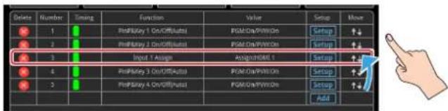
Deleting a function
-
In step 4 of "Recording a Macro" (p. 75), bring up the operation list.
-
Touch the
(Delete) icon to the left of the operation you want to delete.
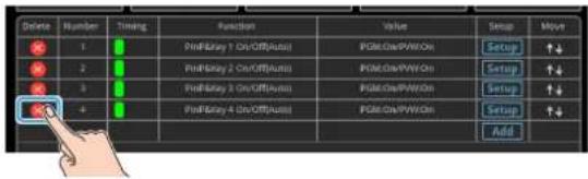
- Touch
.

This deletes the operation line.

MEMO
What's the difference between "Preview" and "Execute"?
When you touch
Directly recording the panel operations to a macro
You can record the panel operations to a macro, just as you did them.

: Panel operations that can't be recorded to a macro
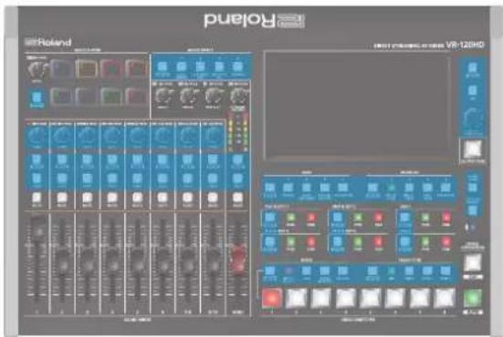
- In step 4 of "Recording a Macro" (p. 75), bring up the operation list.
- Touch
.
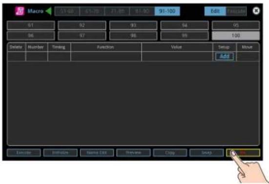
The macro recording screen appears.

- Operate the controls you want to record.
Each time you operate a control, the operation is added to the list.
* To stop recording, touch
* Touch
- Touch
to close the screen.
This confirms the operations you've recorded.
Executing a Macro
Only for macros 1–8
- Press the [MACRO] button.
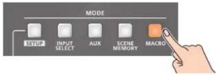
- Press the VIDEO SWITCHER button corresponding to the number of the macro you wish to execute.

Orange: Macros with a recorded function
Unit: Macros without a recorded function
This executes the macro.
Macro 1-100
- Press the [MACRO] button.

- Press the MODE [SETUP] button.
- Touch
.

This shows the macro execution screen.
- Touch the macro (1–100) you want to execute.
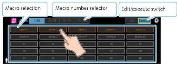
This executes the macro.
MEMO
Assigning macros to the VIDEO SWITCHER buttons
You can change which macros are assigned to each VIDEO SWITCHER button.
Press the [MENU] button and select "Macro" → "Button Assign" and then the menu items listed below to assign macros (1–100) to the respective VIDEO SWITCHER buttons.
Copying Macro Settings
Here's how to copy the settings from one macro to another.
- Follow steps 1–3 in "Recording a Macro" (p. 75) to bring up the macro setup screen.
- Touch
.
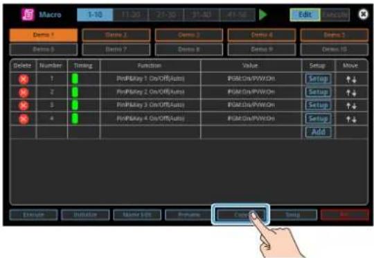
The "Copy" text blinks.
- Touch the macros: first the copy source and then the copy destination.

A confirmation message appears.
* If you decide to cancel, press the [EXIT] button.
- Use the [VALUE] knob to select "OK", and then press the [VALUE] knob.
The macro settings are copied.
Swapping the Macro Settings
Here's how to swap settings between macros.
- Follow steps 1–3 in "Recording a Macro" (p. 75) to bring up the macro setup screen.
- Touch
.
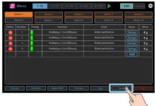
The "Swap" text blinks.
- Touch the two macros to swap.
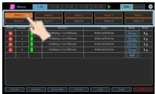
A confirmation message appears.
* If you decide to cancel, press the [EXIT] button.
- Use the [VALUE] knob to select "OK", and then press the [VALUE] knob.
This swaps the settings of the macros.
Initializing a Macro
You can initialize a macro and completely erase its settings.
- Follow steps 1–3 in "Recording a Macro" (p. 75) to bring up the macro setup screen.
- Touch
.

The "Initialize" text blinks.
- Touch the macro to initialize.
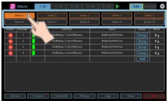
A confirmation message appears.
* If you decide to cancel, press the [EXIT] button.
- Use the [VALUE] knob to select "OK", and then press the [VALUE] knob.
The macro is initialized.
MEMO
About the macro demo data
Once you perform a factory reset (p. 99), any demo data you have edited or deleted is restored to its factory default settings.
Renaming a Macro
Here's how to rename a macro.
- Follow steps 1–3 in "Recording a Macro" (p. 75) to bring up the macro setup screen.
-
Touch the macro to rename.
-
Touch
.
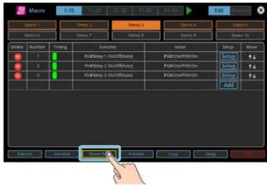
This brings up the software keyboard for input.
- Input the macro name.
* You can input up to 8 characters.
- Touch
in software keyboard.
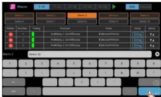
This changes the macro's name.

Saving/Loading the Macro Settings
You can group together the macro settings (1–100) into a single file (.RMC) and save it to a storage (SD card, USB flash drive,) connected to the VR-120HD. You can access the saved macro setting file on the storage and load it into the unit for use when needed.
* The macro setting file is saved to and recalled from the "Roland/VR-120HD/macro" folder.
NOTE
- When using a SD card or USB flash drive for the first time, you must format it using the VR-120HD (p. 13).
- Never turn off the power or remove the SD card or USB flash drive while the message "Processing..." is shown.
- Depending on the SD card or USB flash drive, it may take some time to be recognized.
Saving a new file
1. Insert the SD card into the SDXC card slot.
* When using a USB flash drive, connect the USB flash drive to the USB HOST port.
2. [MENU] button → "Macro" → select "Save To Storage", and press the [VALUE] knob.

The macro setting files in the storage are listed.
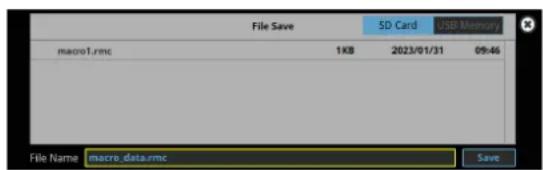
* Use the "SD Card" or "USB Memory" selector at the top right-hand corner of the screen to switch between the storage media to load from.
3. Select "File Name" and press the [VALUE] knob.
This brings up the software keyboard for input.
4. Input the macro setting file name.
* You can input up to 32 characters.
5. Touch in software keyboard.
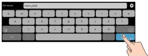
6. Use the [VALUE] knob to select "Save", and then press the [VALUE] knob.
A confirmation message appears.
![ROLAND VR-120HD - Use the [VALUE] knob to select "Save", and then press the [VALUE] knob. - 1](/content/2026/05/915095/images/e76ef8ea32cb7afc1eb1957371e2a4959947eefa4a194fd47969547e5c76685d.jpg)
* If you decide to cancel, press the [EXIT] button.
7. Use the [VALUE] knob to select "OK", and then press the [VALUE] knob.
The macro settings file (.RMC) is saved to the storage. When the operation is finished, the message "Completed" appears.
8. Press the [MENU] button to close the menu.
Overwrite-saving
1. Insert the SD card into the SDXC card slot.
* When using a USB flash drive, connect the USB flash drive to the USB HOST port.
2. [MENU] button → "Macro" → select "Save To Storage", and press the [VALUE] knob.

The macro setting files in the storage are listed.

* Use the "SD Card" or "USB Memory" selector at the top right-hand corner of the screen to switch between the storage media to load from.
3. Touch the macro settings file that you want to overwrite.
The filename shown in the list of filenames is used.
4. Use the [VALUE] knob to select "Save", and then press the [VALUE] knob.
A confirmation message appears.
* If you decide to cancel, press the [EXIT] button.
5. Use the [VALUE] knob to select "OK", and then press the [VALUE] knob.
The macro settings file is overwritten. When the operation is finished, the message "Completed" appears.
6. Press the [MENU] button to close the menu.
Loading
Here's how to load the macro settings that are saved on a storage. Loading the settings overwrites the current settings for the macros (1–100).
1. Insert the SD card into the SDXC card slot.
* When using a USB flash drive, connect the USB flash drive to the USB HOST port.
2. [MENU] button → "Macro" → select "Load From Storage", and press the [VALUE] knob.
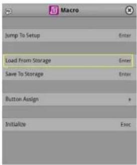
The macro setting files in the storage are listed.

* Use the "SD Card" or "USB Memory" selector at the top right-hand corner of the screen to switch between the storage media to load from.
3. Touch the macro settings file that you want to recall.
A confirmation message appears.

* If you decide to cancel, press the [EXIT] button.
4. Use the [VALUE] knob to select "OK", and then press the [VALUE] knob.
The macro settings are loaded. When the operation is finished, the message "Completed" appears.
5. Press the [MENU] button to close the menu.
Initializing All Macros
Here's how to initialize and erase all the macros.
1. [MENU] button → "Macro" → select "Initialize", and press the [VALUE] knob.
A confirmation message appears.

* If you decide to cancel, press the [EXIT] button.
2. Use the [VALUE] knob to select "OK", and then press the [VALUE] knob.
The macros are initialized.
3. Press the [MENU] button to close the menu.
Combining Scene Memories and Macros for Operations (Sequencer)
The sequencer function lets you record functions such as recalling scene memories or macros, and then execute them in the order you specify.
This lets you recreate the desired functions like editing the screen layout or inserting a title, by preparing the functions in line with how the events progress and then simply pressing the [AUTO] button. This feature is useful for smoothly carrying out operations at the place where you're working.
Recording to the Sequencer
Three types of functions can be recorded in the sequencer, including recalling a scene memory, executing a macro and switching between final output videos. Create a list of the functions you want to execute in order.
A list can contain up to 1,000 functions.
MEMO
- The demo data in this unit that's available by factory default includes a list of recorded functions. You can completely erase the contents of this list by initializing it (p. 87).
- When the sequencer function is assigned to a USER button, you can set this from the setup screen.
* The sequencer function is assigned to the USER [4] button by factory default.
1. Press the USER [SETUP] button.
The User Assign screen appears.
2. Touch User 4 .
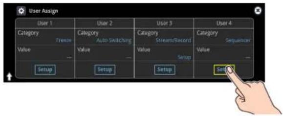
The list of operations recorded in the sequencer is shown.
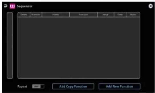
3. Touch .

The operation is added to the first line of the list.
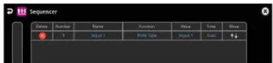
4. Touch the "Function" column of the line you want to add, and select the operation to record to the sequencer.

| Value Explanation | |
| PGM Take | Switches the final output video. |
| Scene Memory | Recalls a scene memory. |
| Macro | Executes a macro. |
5. Configure the related parameters.

6. Repeat steps 3–5 to finish making the list.
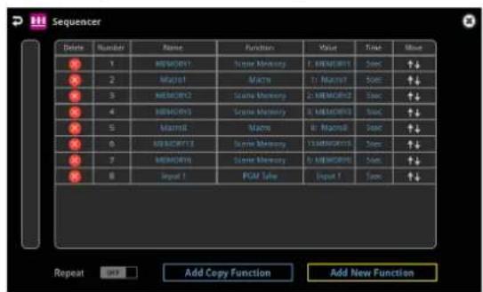
7. Press the [EXIT] button to close the menu.
Editing a list
You can edit the contents of a function, change the order in which it is executed, or copy/delete a function while creating a list or after you've finished the list.
Editing the contents of a function
-
In step 2 of "Recording to the Sequencer" (p. 82), bring up the operation list.
-
Touch the "Function" column of the line you want to edit, and edit the operation to record to the sequencer.
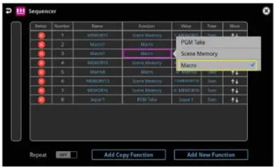
- Configure the related parameters.
| Menu Value | Explanation | |
| Function | Sets the operation to record to the sequencer.* The related menu is shown according to the operation you set. | |
| PGM Take | Switches the final output video. | |
| Scene Memory | Recalls a scene memory. | |
| Macro | Executes a macro (a series of recorded operations). | |
| Name — | Shows the name of the operation. | |
| Time | Sets the operation when auto sequence is on. | |
| Pause | Pauses the auto sequence. | |
| Auto | Executes the next operation in the sequence. | |
| 1-5-120sec | Executes the next operation after delaying for a specified amount of time. | |
Moving a function
-
In step 2 of "Recording to the Sequencer" (p. 82), bring up the operation list.
-
Use the <>(Move) icons shown on the right-hand side to drag the operation line you want to move to the destination, and release it.

This moves the operation line that you dragged.

Copying a function
- In step 2 of "Recording to the Sequencer" (p. 82), bring up the operation list.
- Touch
.

The "Add Copt Function" text blinks.
- Touch the copy source line.
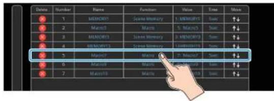
The line is copied and added to the last line of the list.

Deleting a function
- In step 2 of "Recording to the Sequencer" (p. 82), bring up the operation list.
- Touch the
(Delete) icon to the left of the operation you want to delete.

- Touch
.
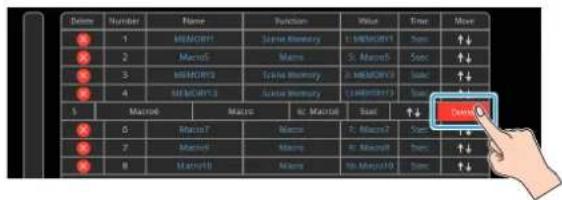
This deletes the operation line.
| Delame | Number | Name | Function | Value | Time | Move |
| 1 | 1 | MEMORY1 | XuXi Memory | L. MEMORY1 | Sun | ↑↓ |
| 2 | 2 | Macr5 | Macro | S. Macr5 | Sun | ↑↓ |
| 3 | 3 | MEMORY3 | Screen Memory | S. MEMORY3 | Sun | ↑↓ |
| 4 | 4 | MEMORY3 | Screen Memory | F. MEMORY3 | Sun | ↑↓ |
| 5 | 5 | Macr7 | Macro | P. Macr7 | Sun | ↑↓ |
| 6 | 6 | Macr8 | Macro | S. Macr8 | Sun | ↑↓ |
| 7 | 7 | Macr8 | Macro | Tg. Macr8 | Sun | ↑↓ |
Running the Sequencer
Press the button to make the functions recorded in the sequencer execute one at a time.
1. Press the USER [4] (SEQUENCER) button to turn the sequencer function on (the button lights up).
The sequencer execution screen is shown, where you can check the list of operations that are recorded to the sequencer.

2. Press the [AUTO] (NEXT) button.

The first function in the list is executed.
The button blinks while the function is executing. When the function ends, the button remains lit.
3. Press the [AUTO] (NEXT) button at the timing when you want the next function to execute.
The function is executed.
[CUT] (PREVIOUS) button
Press the [CUT] button if you want to return to the state at which the previous function was completed.
MEMO
You can also touch
4. Repeat step 3.
5. Press the USER [4] (SEQUENCER) button again to turn the sequencer function off.
MEMO
Repeatedly executing a function in the list
You can repeatedly execute functions that are in a list. Once the last function is finished, press the [AUTO] button to execute the function at the beginning of the list.
Use the [MENU] button → "Sequencer" → and set "Repeat Execute" to "ON".
Executing a function from the middle of the list
When you directly touch the desired operation in the list,
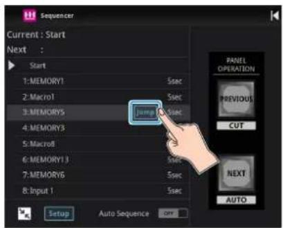
Making the Sequencer Run Automatically (Auto Sequence)
Use the auto sequence feature when you want to make the functions recorded in the sequencer execute automatically.
Configuring the auto sequence settings
Set the action or function that's executed when the sequencer advances to the next function. You can add some delay time before the next function is executed, or pause the execution of a function.
- In step 2 of "Recording to the Sequencer" (p. 82), bring up the operation list.
- To change what happens when moving to the next operation, touch the "Time" column of the line you want to edit.

| Value Explanation | |
| Pause | Pauses the auto sequence. |
| Auto | Executes the next operation in the sequence. |
| 1-120sec | Executes the next operation after delaying for a specified amount of time. |
- Repeat step 2.
Running the auto sequence
- Press the USER [4] (SEQUENCER) button to turn the sequencer function on (the button lights up).
The list of operations recorded in the sequencer is shown.
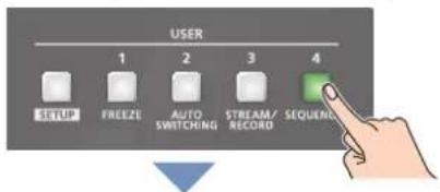

This lets you check which action occurs when the sequencer moves to the next operation.
- Touch
to turn the auto sequencer function on.

The functions in the list are executed, starting at the beginning. The [AUTO] button blinks while a function is executing.
When the last function is finished, the sequence stops automatically.
When a function is set to "PAUSE"
When the function is finished, auto sequence is paused. You can press the [AUTO] (NEXT) button to manually execute the next function.
* When executing a function that's set to a value other than "PAUSE", the auto sequence is resumed.
- Touch
again to turn off the auto sequence. - Press the USER [4] (SEQUENCER) button again to turn the sequencer function off.
MEMO
You can repeatedly execute functions that are in a list. When the last function is finished, the sequencer returns to the beginning.
Use the [MENU] button → "Sequencer" → and set "Repeat Execute" to "ON".
Saving/Loading the Sequencer Settings
You can save the sequencer settings as a single file (.RSQ) to a storage (SD card, USB flash drive) connected to the VR-120HD.
You can access the saved sequence file on the storage and load it into the unit for use when needed.
* The sequence file is saved to and recalled from the "Roland/VR-120HD/sequencer" folder.
NOTE
- When using a SD card or USB flash drive for the first time, you must format it using the VR-120HD (p. 13).
- Never turn off the power or remove the SD card or USB flash drive while the message "Processing..." is shown.
- Depending on the SD card or USB flash drive, it may take some time to be recognized.
Saving a new file
- Insert the SD card into the SDXC card slot.
* When using a USB flash drive, connect the USB flash drive to the USB HOST port.
- [MENU] button → "Sequencer" → select "Save To Storage", and press the [VALUE] knob.

The sequence files in the storage are listed.

* Use the "SD Card" or "USB Memory" selector at the top right-hand corner of the screen to switch between the storage media to load from.
- Select "File Name" and press the [VALUE] knob.
This brings up the software keyboard for input.
- Input the sequence file name.
* You can input up to 32 characters.
- Touch
in software keyboard.

- Use the [VALUE] knob to select "Save", and then press the [VALUE] knob.
A confirmation message appears.

* If you decide to cancel, press the [EXIT] button.
- Use the [VALUE] knob to select "OK", and then press the [VALUE] knob.
The sequence file (.RSQ) is saved to the storage. When the operation is finished, the message "Completed" appears.
- Press the [MENU] button to close the menu.
Overwrite-saving
- Insert the SD card into the SDXC card slot.
* When using a USB flash drive, connect the USB flash drive to the USB HOST port.
- [MENU] button → "Sequencer" → select "Save To Storage", and press the [VALUE] knob.
The sequence files in the storage are listed.

* Use the "SD Card" or "USB Memory" selector at the top right-hand corner of the screen to switch between the storage media to load from.
- Touch the sequence file that you want to overwrite.
The filename shown in the list of filenames is used.
- Use the [VALUE] knob to select "Save", and then press the [VALUE] knob.
A confirmation message appears.
* If you decide to cancel, press the [EXIT] button.
- Use the [VALUE] knob to select "OK", and then press the [VALUE] knob.
The sequence file is overwritten. When the operation is finished, the message "Completed" appears.
- Press the [MENU] button to close the menu.
Loading
Here's how to load the sequencer settings that are saved on a storage. When you load settings, the current sequencer settings are overwritten.
- [MENU] button → "Sequencer" → select "Load From Storage", and press the [VALUE] knob.
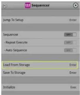
The sequence files in the storage are listed.
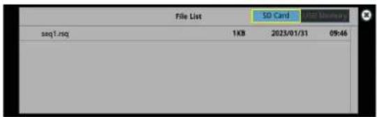
* Use the "SD Card" or "USB Memory" selector at the top right-hand corner of the screen to switch between the storage media to load from.
- Touch the sequence file that you want to load.
A confirmation message appears.
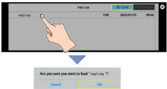
* If you decide to cancel, press the [EXIT] button.
- Use the [VALUE] knob to select "OK", and then press the [VALUE] knob.
The sequencer settings are loaded. When the operation is finished, the message "Completed" appears.
- Press the [MENU] button to close the menu.
Initializing the Sequencer
Here's how to initialize the sequencer and erase all the settings.
- [MENU] button → "Sequencer" → select "Initialize", and press the [VALUE] knob.
A confirmation message appears.
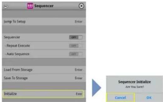
* If you decide to cancel, press the [EXIT] button.
-
Use the [VALUE] knob to select "OK", and then press the [VALUE] knob.
-
Press the [MENU] button to close the menu.
MEMO
About the sequencer demo data
Once you perform a factory reset (p. 99), any demo data you have edited or deleted is restored to its factory default settings.
Backing Up and Restoring the Unit's Settings
You can group together the unit's settings into a single file (.VR120) and back up it to a storage (SD card, USB flash drive) connected to the VR-120HD. You can access the backed up setting file on the storage and restore it into the unit for use when needed.
* The setting file is saved to and recalled from the "Roland/VR-120HD/backup" folder.
NOTE
- When using a SD card or USB flash drive for the first time, you must format it using the VR-120HD (p. 13).
- Never turn off the power or remove the SD card or USB flash drive while the message "Processing..." is shown.
- Depending on the SD card or USB flash drive, it may take some time to be recognized.
Backing Up
Saving a new file
- Insert the SD card into the SDXC card slot.
* When using a USB flash drive, connect the USB flash drive to the USB HOST port. - [MENU] button → "SD Card/USB Memory" → select "Backup All Settings", and press the [VALUE] knob.
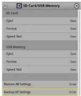
The backup files in the storage are listed.
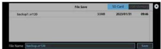
* Use the "SD Card" or "USB Memory" selector at the top right-hand corner of the screen to switch between the storage media to load from.
- Select "File Name" and press the [VALUE] knob.
This brings up the software keyboard for input.
- Input the backup file name.
* You can input up to 32 characters.
- Touch
in software keyboard.

- Use the [VALUE] knob to select "Save", and then press the [VALUE] knob.
A confirmation message appears.

* If you decide to cancel, press the [EXIT] button.
- Use the [VALUE] knob to select "OK", and then press the [VALUE] knob.
The settings file (.VR120) is backed up on the storage. When the operation is finished, the message "Completed" appears.
- Press the [MENU] button to close the menu.
MEMO
Some settings are not saved to the file, such as the "Test Pattern" and "Test Tone" settings in the System menu.
Overwrite-saving
1. Insert the SD card into the SDXC card slot.
* When using a USB flash drive, connect the USB flash drive to the USB HOST port.
2. [MENU] button → "SD Card/USB Memory" → select "Backup All Settings", and press the [VALUE] knob.
The backup files in the storage are listed.

* Use the "SD Card" or "USB Memory" selector at the top right-hand corner of the screen to switch between the storage media to load from.
3. Touch the backup file that you want to overwrite.
The filename shown in the list of filenames is used.
4. Use the [VALUE] knob to select "Save", and then press the [VALUE] knob.
A confirmation message appears.
* If you decide to cancel, press the [EXIT] button.
5. Use the [VALUE] knob to select "OK", and then press the [VALUE] knob.
The settings file is overwrite-saved. When the operation is finished, the message "Completed" appears.
6. Press the [MENU] button to close the menu.
MEMO
Some settings are not saved to the file, such as the "Test Pattern" and "Test Tone" settings in the System menu.
Restoring
Here's how to restore this unit's settings that you saved on a storage. When you restore settings, the current settings are overwritten.
1. [MENU] button → "SD Card/USB Memory" → select "Restore All Settings", and press the [VALUE] knob.
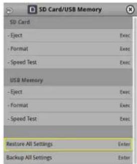
The backup files in the storage are listed.
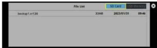
* Use the "SD Card" or "USB Memory" selector at the top right-hand corner of the screen to switch between the storage media to load from.
2. Touch the settings file that you want to restore.
A confirmation message appears.

* If you decide to cancel, press the [EXIT] button.
3. Use the [VALUE] knob to select "OK", and then press the [VALUE] knob.
The settings are restored. When the operation is finished, the message "Completed" appears.
Assigning Functions to the USER Buttons
You can assign the functions you want to the USER [1]–[4] buttons. By doing this, the function you assigned is executed when you press a USER button.
The functions printed on the operation panel are assigned to the USER buttons by factory default.
- Press the USER [SETUP] button.
The User Assign screen appears.
- Select the function by touching the "Category" and "Value" of the USER button you want to reassign.

Category
| Value | Explanation |
| N/A No function is assigned. | |
| Freeze Turns the freeze function on/off. | |
| Auto Switching Turns the auto switching function on/off. | |
| Input Assign | Each time you press a button, the video source assigned to the specified cross-point button switches to the following sources in order: HDMI 1 → 6 → SDI 1 → 6 → STILL 1 → 16 |
| Still Output | Pauses the normal output, and previews or final outputs a cut of the still image. |
| Video Player Output | Pauses the normal output, and cuts to the preview/final output of the video player image. |
| Load Memory Recalls a scene memory. | |
| Input Scan | Each time you press a button, the Input 1-8 video changes in order. |
| Scene Memory Scan | Each time you press a button, scene memories 1-32 are recalled in order. |
| PinP&Key 1-4 Scan | The PinP & KEY 1-4 inset screen videos switch in order each time you press the button. |
| DSK 1, 2 Scan | The DSK 1 and 2 caption video switches in order each time you press the button. |
| External Rec Control | Controls the recorder's video record start/stop if a recorder that supports REC control functionality is connected (p. 90). |
| Macro Execute | Executes a macro (a series of recorded operations). |
| Sequencer Shows the sequencer execution screen. | |
| Stream/Record Assigns a streaming-related function. | |
| Video Player Assigns a video player-related function. | |
| GPO (One Shot) | Outputs a control signal for 0.5 seconds. |
| GPO (Alternate) | The control signal output is switched on/off while the button is pressed. |
| Camera Control | Turns the camera control function on/off. |
| System Assigns a system-related function. | |
Value
Configures the detailed settings related to "Category".
- Press the lit [SETUP] button to close the setup screen.
Controlling an External Recorder's Video Record Start/Stop from the VR-120HD
Connect a recorder that supports REC control functionality via HDMI to control rec start/stop on the recorder from the VR-120HD (REC control function).
For more about recorders that support the REC control function, refer to the Roland website.
https://proav.roland.com/
Setting
Assigning a USER button
To use the external REC control function, you must assign the recorder's video recording start/stop functions to a USER button.
- Assign the "External Rec Control" function to a USER button by following the steps in "Assigning Functions to the USER Buttons" (p. 90).
Turning REC control on/off
- [MENU] button → "Video Output" → "HDMI Out 1-3" → and set "External Rec Control" to "ON".
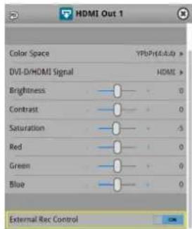
Operation
- Press the USER button to which Rec Start/Stop is assigned.
Each time you press the button, the recorder switches between video record start/stop.

Lit: Now recording Unlit: Stopped
* This example shows the function assigned to the USER [3] button.
NOTE
The lights of the USER buttons show the status of the VR-120HD, and are not linked with the recorder's status.
For instance, if the recorder stops recording for some reason while the USER button are lit, these buttons do not automatically go dark in response.
Remotely Controlling a PTZ Camera
You can connect up to twelve cameras via the DIRECT STREAM port and remotely control them from the VR-120HD.
This allows you to control cameras made by JVC, Panasonic, Canon, PTZOptics, and Avonic, and cameras that support VISCA over IP (such as Sony).
* Refer also to the owner's manual of your camera.
Network Settings on the Camera
In order to control a camera from the VR-120HD, you need to make network settings on the camera. You can register up to twelve cameras.
Assigning a USER button
To use the camera control function, you must assign the camera control function to a USER button.
- Assign the "Camera Control" function to a USER button by following the steps in "Assigning Functions to the USER Buttons" (p. 90).
Network settings for the camera
- Press the USER [SETUP] button.
The User Assign screen appears.
- Touch
for the USER button to which you assigned the camera control function.

The camera control setup screen appears.
- Touch the screen to configure the camera's network settings.

| Menu item Explanation | |
| Camera ID Selects the camera to be controlled. | |
| Protocol Specifies the camera's protocol. | |
| IP Address Input the camera's IP address. | |
| Login Name | When "Protocol" is "JVC"Touchto bring up the software keyboard for input, and enter the log-in name needed to connect with the camera. |
| Password | When "Protocol" is "JVC"Touchto bring up the software keyboard for input, and enter the password needed to connect with the camera. |
- Press the lit [SETUP] button to close the setup screen.
Registering Camera Settings in a Preset
Up to 8 sets of settings such as camera position and focus can be registered as presets.
A registered preset can be recalled when needed.
* Presets are saved in the camera itself.
-
In step 2 of "Network Settings on the Camera", bring up the camera control setup screen.
-
Touch the screen to operate the camera settings.

| Menu item Explanation | ||
| Positioner | Adjusts the horizontal/ vertical position.Drag on the screen to operate the camera. | |
| Pan Tilt Speed | Adjusts the speed at which the camera changes direction. | |
| Zoom Adjusts the zoom position. (*1) | ||
| Focus Adjusts the focal point. (*1) | ||
| Auto Focus | When this is “ON”, the focal point is set automatically. | |
| Exposure Specifies the exposure mode. | ||
| Tally Channel | Specifies the connector from which the camera video is input. When the camera video from the VR-120HD is the final output, the camera’s tally light is lit. | |
(*1) You can operate the camera while touching the screen.
-
Touch
. -
Touch the preset number (Camera Preset 1-8) area where you want to register the settings.

- Press the lit [SETUP] button to close the setup screen.
Recalling a Preset
This shows you how to recall the presets registered in your camera. You can also recall presets from multiple cameras at the same time.
- In step 3 of "Network Settings on the Camera", bring up the camera control setup screen.
Recalling presets from a single camera
| Menu item Explanation | |
| Camera ID | Select the camera from which you want to recall a preset. |
| All Cameras Load Turns | "All Cameras Load" off. |
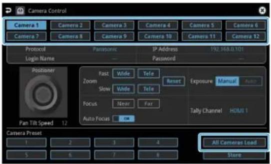
Recalling from all cameras simultaneously
| Menu item Explanation | |
| All Cameras Load Turns | "All Cameras Load" on. |

- Touch the preset number (Camera Preset 1–8) area you want to recall.

- Press the lit [SETUP] button to close the setup screen.
Recalling presets with the buttons
By assigning a USER button to the camera control function, you can recall presets using the button.
To use the camera control function, you must assign the camera control function to a USER button.
Assigning a USER button
- Assign the "Camera Control" function to a USER button by following the steps in "Assigning Functions to the USER Buttons" (p. 90).
- On the camera control setup screen, set "All Cameras Load" to on (all cameras) or off (a single camera).
- Press the USER button to which you've assigned the camera control function to turn camera control on (the button lights up).
Recalling a preset
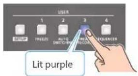
* This example shows the function assigned to the USER [3] button.
- Touch <◀> or <▶> to change the "Camera ID", and select the camera (1–12) for which you want to recall the preset.

- Press the VIDEO SWITCHER button for the preset number whose setting you want to recall.

The settings are recalled from the cameras.
- Press the USER button again to turn the camera control function off.
Using a Footswitch
You can use a footswitch connected to the CTL/EXP 1 and 2 jacks to control the VR-120HD with your foot. You can assign various functions to the footswitch.
- [MENU] button → "Ctl/Exp" → "Ctl/Exp 1" or "Ctl/Exp 2" → select "Ctl/Exp Type", and press the [VALUE] knob.

- Set the connected device to "Ctl A & Ctl B" (the footswitch) using the [VALUE] knob, and press the [VALUE] knob.
- Use the [VALUE] knob to select Ctl A Or Ctl B "Category" and "Value", and press the [VALUE] knob.
- Use the [VALUE] knob to select the function that you want to assign to Ctl A or Ctl B of the footswitch, and press the [VALUE] knob.
Category
| Value Explanation | |
| N/A No function is assigned. | |
| PGM Channel Select | Switches the video sent to the PGM bus. |
| PST Channel Select | Switches the video sent to the PST bus. |
| AUX Channel Select Switches the video sent to the AUX bus. | |
| Input 1–8 Assign Changes the video assigned to Input 1–8. | |
| Still Output | Pauses the normal output, and previews or final outputs a cut of the still image. |
| Video Player Output | Pauses the normal output, and cuts to the preview/final output of the video player image. |
| PinP&Key 1–4 Source | Switches the video source of the inset screen. |
| DSK 1, 2 Source Switches the DSK video source. | |
| Button Control | This works the same as when you press the button selected in “VALUE”. |
| Audio Input Mute | Turns the mute function on/off for the input audio. |
| Audio Output Mute | Turns the mute function on/off for the output audio. |
| Audio Input Solo | Turns the solo function on/off for the input audio. |
| Audio Output Solo | Turns the solo function on/off for the output audio. |
| Voice Changer Turns the voice changer on/off. | |
| Auto Mixing Turns the auto mixing on/off. | |
| Reverb (Momentary) | Reverb turns on only while you press the footswitch. |
| Reverb (Alternate) | Turns reverb on/off. |
| Output Fade | The final output video fades in/out. |
| Load Memory | Recalls a scene memory. |
| Input Scan | Each time you press the footswitch, the Input 1–8 video changes in order. |
| Scene Memory Scan | Each time you press the footswitch, scene memories 1–32 are recalled in order. |
| Value Explanation | |
| PinP&Key 1-4 Scan | The PinP & KEY 1-4 inset screen videos switch in order each time you press the footswitch. |
| DSK 1, 2 Scan | The DSK 1 and 2 caption video switches in order each time you press the footswitch. |
| Macro Execute | Executes a macro (a series of recorded operations). |
| Sequencer | When the sequencer function is on, this works the same as when you press the button selected in “VALUE”. |
| GPO (One Shot) | Outputs a control signal for 0.5 seconds. |
| GPO (Alternate) | The control signal output is switched on/off with each press of the footswitch. |
Value
Configures the detailed settings related to "Category".
- Press the [MENU] button to close the menu.
MEMO
- See "Connecting a Footswitch" (p. 9) for how to connect a footswitch to this unit.
- If a single-pedal type footswitch such as the BOSS FS-5U is connected using a phone cable (mono), the function assigned by "Ctl B" is enabled.
Using an Expression Pedal
You can use an expression pedal connected to the CTL/EXP 1 and 2 jacks to control the VR-120HD with your foot.
Adjusting the Pedal (Pedal Calibration)
The first time you use an expression pedal, you must calibrate (adjust) the pedal so that it will operate optimally.
In some cases, an expression pedal might no longer operate optimally due to the passage of time or changes in the operating conditions. If you notice problems such as slight movements of the pedal causing a major change in volume, or if the video fails to switch when you press the pedal, you should execute calibration.
- [MENU] button → "Ctl/Exp" → "Ctl/Exp 1" Or "Ctl/Exp 2" → select "Ctl/Exp Type", and press the [VALUE] knob.

- Set the connected device to "Exp" (the expression pedal) using the [VALUE] knob, and press the [VALUE] knob.
- Use the [VALUE] knob to select "Exp Calibration", and press the [VALUE] knob.
The Exp Calibration screen appears.
![Exp 1 Calibration Set Exp 1 Lower Position and Press [ENTER] max min 0](/content/2026/05/915095/images/6e16672b9680558c998c8bfbadf33fbd8673e433b98533b2efb69435b88b22e7.jpg)
- As directed by the screen, step on the pedal in the fully heel-down position, and press the [VALUE] knob.
- As directed by the screen, step on the pedal in the fully toedown position, and press the [VALUE] knob.
When the "Completed" indication appears, calibration is completed.
- Press the [MENU] button to close the menu.
MEMO
You should normally use the EV-5 with its minimum volume knob left in the zero position. If you change the position of the minimum volume knob, you must execute pedal calibration.
Assigning a Function to the Pedal
You can assign various functions to the expression pedal.
- [MENU] button → "Ctl/Exp" → "Ctl/Exp 1" Or "Ctl/Exp 2" → select "Ctl/Exp Type", and press the [VALUE] knob.

- Set the connected device to "Exp" (the expression pedal) using the [VALUE] knob, and press the [VALUE] knob.
- Use the [VALUE] knob to select Exp "Category" and "Value", and press the [VALUE] knob.
- Use the [VALUE] knob to select the function that you want to assign to the expression pedal, and press the [VALUE] knob.
Category
| Value Explanation | |
| N/A No function is assigned. | |
| Video Fader | Fade:Operates the video fader. |
| Cut:Cuts between the final output video and the preview video. | |
| Still Output | Pauses the normal output, and previews or final outputs a cut of the still image. |
| Video Player Output | Pauses the normal output, and cuts to the preview/final output of the video player image. |
| Audio Input Level Adjusts the input volume. | |
| Audio Output Level Adjusts the output volume. | |
| Voice Changer | Adjusts the balance between the unprocessed voice (0) and the voice processed by the effect (100). |
| Reverb Level | Adjusts the amount of sound that is returned from the reverb (return level). |
Value
Configures the detailed settings related to "Category".
- Press the [MENU] button to close the menu.
Control Using the TALLY/GPIO Connector
You can use control signals inputted to the TALLY/GPIO connector via GPI to remotely control the VR-120HD from an external device.
Also, you can output tally signals or GPO control signals from the TALLY/GPIO connector.
Specification of the TALLY/GPIO Connector
Pin layout

Tally output
| Trigger method Open collector |
| Maximum input 12 V/120 mA |
Control input
| Trigger method No-voltage contact (make-contact) triggering |
| Contact capacity DC 24 V 0.1 A or higher |
| Input method Photocoupler |
Pin assignments
| Pin no. | Pin name Function (default value) | |
| 1 | TALLY/GPO 1 | PGM HDMI 1 |
| 2 | TALLY/GPO 2 | PST HDMI 1 |
| 3 | TALLY/GPO 3 | PGM HDMI 2 |
| 4 | TALLY/GPO 4 | PST HDMI 2 |
| 5 | TALLY/GPO 5 | PGM HDMI 3 |
| 6 | TALLY/GPO 6 | PST HDMI 3 |
| 7 | TALLY/GPO 7 | PGM HDMI 4 |
| 8 | TALLY/GPO 8 | PST HDMI 4 |
| 9 | TALLY/GPO 9 | PGM HDMI 5 |
| 10 | TALLY/GPO 10 | PST HDMI 5 |
| 11 | TALLY/GPO 11 | PGM HDMI 6 |
| 12 | TALLY/GPO 12 | PST HDMI 6 |
| 13 | TALLY/GPO 13 | GPO 1 |
| 14 | TALLY/GPO 14 | GPO 2 |
| 15 | TALLY/GPO 15 | GPO 3 |
| 16 | TALLY/GPO 16 | GPO 4 |
| 17 | GND | |
| 18 | GPI 1 | Not assigned |
| 19 | GPI 2 | Not assigned |
| 20 | GPI 3 | Not assigned |
| 21 | GPI 4 | Not assigned |
| 22 | GPI 5 | Not assigned |
| 23 | GPI 6 | Not assigned |
| 24 | GPI 7 | Not assigned |
| 25 | GPI 8 | Not assigned |
Inputting a Control Signal
When an external control signal is input, the functions assigned to GPI 1–8 are executed.
- [MENU] button → "RS-232/Tally/GPO/GPI" → "GPI" → select GPI 1–8 "Category" and "Value", and press the [VALUE] knob.
- Use the [VALUE] knob to select the functions assigned to GPI 1-8, and then press [VALUE].
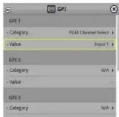
Category
| Value | Explanation |
| N/A | No function is assigned. |
| PGM Channel Select | Switches the video sent to the PGM bus. |
| PST Channel Select | Switches the video sent to the PST bus. |
| AUX Channel Select | Switches the video sent to the AUX bus. |
| Input 1–8 Assign | Changes the video assigned to Input 1–8. |
| Still Output | Pauses the normal output, and previews or final outputs a cut of the still image. |
| Video Player Output | Pauses the normal output, and cuts to the preview/final output of the video player image. |
| PinP&Key 1–4 Source | Switches the video source of the inset screen. |
| DSK 1, 2 Source | Switches the DSK video source. |
| Button Control | This works the same as when you press the button selected in "VALUE". |
| Audio Input Mute | Turns the mute function on/off for the input audio. |
| Audio Output Mute | Turns the mute function on/off for the output audio. |
| Audio Input Solo | Turns the solo function on/off for the input audio. |
| Audio Output Solo | Turns the solo function on/off for the output audio. |
| Voice Changer | Turns the voice changer on/off. |
| Auto Mixing | Turns the auto mixing on/off. |
| Reverb (Momentary) | Reverb turns on only while a control signal is input. |
| Reverb (Alternate) | Turns reverb on/off. |
| Output Fade | The final output video fades in/out. |
| Load Memory Recalls a scene memory. | |
| Input Scan | Each time a control signal is input, the Input 1–8 video changes in order. |
| Scene Memory Scan | Each time a control signal is input scene memories 1–32 are recalled in order. |
| PinP&Key 1–4 Scan | Each time a control signal is input, the PinP&Key 1–4 inset screen videos changes in order. |
| DSK 1, 2 Scan | Each time a control signal is input, the DSK 1 and 2 caption video changes in order. |
| Macro Execute | Executes a macro (a series of recorded operations). |
| Sequencer | When the sequencer function is on, this works the same as when you press the button selected in "Value". |
| GPO (One Shot) | Outputs a control signal for 0.5 seconds. |
| GPO (Alternate) | The control signal output is switched on/off each time a control signal is input. |
Value
Configures the detailed settings related to "Category".
3. Press the [MENU] button to close the menu.
Outputting a Tally Signal
Pins 1–16 of the TALLY/GPIO connector can be used to output a tally. A tally signal is output from the connector pins whenever a VIDEO SWITCHER button is selected.
- [MENU] button → "RS-232/Tally/GPO/GPI" → "Tally/GPO" → select "Tally/GPO 1"-Tally/GPO 16", and press the [VALUE] knob.

- Use the [VALUE] knob to select the tally signal assigned to the connector pins and then press the [VALUE] knob.
| Value | Explanation |
| PGM HDMI 1-6 Video | Video for which the final output is HDMI IN 1-6. |
| PGM SDI 1-6 Video | Video for which the final output is SDI IN 1-6. |
| PGM Still 1-16 The | The final output is still images 1-16. |
| PGM Video Player | The final output is the video from the video player. |
| PGM Input 1-8 | Use the VIDEO SWITCHER [1]-[8] buttons to select the final output video. |
| PST HDMI 1-6 | Video for which the preview output is HDMI IN 1-6. |
| PST SDI 1-6 Video | for which the preview output is SDI IN 1-6. |
| PST Still 1-16 The | preview output is still images 1-16. |
| PST Video Player | The preview output is the video from the video player. |
| PST Input 1-8 | Use the VIDEO SWITCHER [1]-[8] buttons to select the preview output video. |
- Press the [MENU] button to close the menu.
MEMO
Use a settings template to change the assignments for the connector pins all at once.
Select a template from "Template" in the Tally/GPO menu and then press the [VALUE] knob to apply the settings.
Outputting a Control Signal
You can use connector pins 1–16 of the TALLY/GPIO connector as GPOs to output control signals.
Assigning the GPOs
You can assign pins 1–16 of the TALLY/GPIO connector to the GPOs (1–16) in order to output control signals.
- [MENU] button → "RS-232/Tally/GPO/GPI" → "Tally/GPO" → select "Tally/GPO 1"-Tally/GPO 16", and press the [VALUE] knob.

-
Use the [VALUE] knob to select one of "GPO 1"- "GPO 16", and press the [VALUE] knob.
-
Press the [MENU] button to close the menu.
MEMO
Use a settings template to change the assignments for the connector pins all at once.
Select a template from "Template" in the Tally/GPO menu and then press the [VALUE] knob to apply the settings.
Outputting a control signal
Control signals are outputted when you operate a USER button, footswitch or other control to which a GPO output function has been assigned.
Using the USER buttons
The USER buttons light up while control signals are being output.
→"Assigning Functions to the USER Buttons" (p. 90)
Using a footswitch
→"Using a Footswitch" (p. 93)
Inputting an external control signal (GPI)
→"Inputting a Control Signal" (p. 95)
Using Smart Tally
Roland's own Smart Tally system turns your smart device or computer that's connected to the VR-120HD into a tally box. This lets you access your smart device or computer via a wireless LAN access point to display a tally on that device.
Connecting via a Wireless LAN Router
Connect your Wi-Fi enabled smart device or computer to the wireless LAN router via Wi-Fi.
* If you connect multiple smart devices or computers, operation might be slower.
- Use a LAN cable to connect the LAN port on your wireless LAN master device to the DIRECT STREAM port on the VR-120HD.

- Turn on the wireless LAN master device, and connect your smart device or computer via wireless LAN (Wi-Fi).
Enable the DHCP function of the wireless LAN router.
* For details on how to connect the wireless LAN (Wi-Fi), refer to the manual of the device that you're using.
-
Power-on the VR-120HD.
-
[MENU] button → "Network" → "LAN Setup" → set "Configure" to "Using DHCP", and press the [VALUE] knob.
The IP address, subnet mask, and default gateway are obtained automatically.

-
Use the [VALUE] knob to select "Apply", and press the [VALUE] knob.
-
Use the [VALUE] knob to select "Network Information", and press the [VALUE] knob.
* Network Information screen appears.
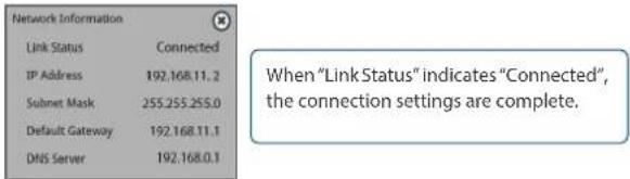
MEMO
If you fix the IP address, you'll always be able to start Smart Tally with the same IP address.
For details on how to specify a fixed IP address, refer to the manual of the wireless LAN router that you're using.
Starting Smart Tally
- From the VR-120HD's [MENU] button→ "Network"→ select "Network Information", and press the [VALUE] knob.
The Network Information screen appears.

-
Start a browser on your smart device or computer.
-
In the URL input field of your browser, enter the IP address that's shown in the Network Information screen to access the website.
The Smart Tally settings screen appears.
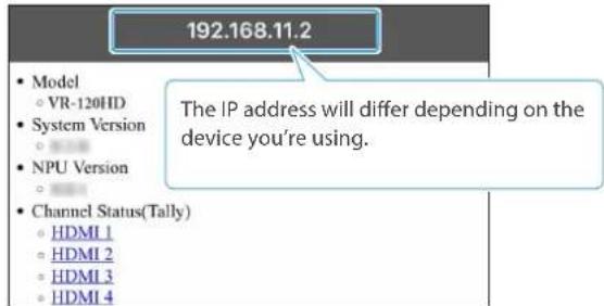
* You can also access the website by scanning a QR code. The QR code is shown when you press "2D Code for Smart Tally" on the screen in step 1.
- In "Channel Status (Tally)", select the video source that you want to assign to the smart device or computer.
The device's display switches to the tally information screen.
This shows the tally information corresponding to the video source output from the VR-120HD.
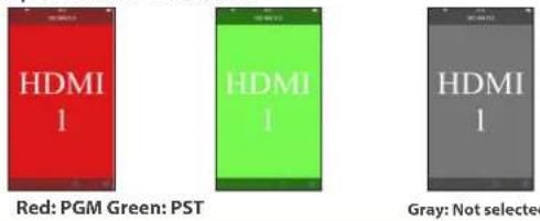
NOTE
- Depending on the network conditions, the wireless LAN (Wi-Fi) communication speed or connection might be unstable, so that the tally indication is not displayed correctly. In this case, reload the page.
- Depending on the version of the browser that you're using, the tally indication might not be displayed correctly. Use the latest version of the browser whenever possible.
Preventing Unintended Operation (Panel Lock)
You can disable operation of the panel's buttons and knobs to prevent unintended operations (Panel Lock function).
1. [MENU] button → "System" → select "Panel Lock", and press the [VALUE] knob.
The Panel Lock menu appears.

2. Use the [VALUE] knob to select a target for panel lock, and press the [VALUE] knob.
| Menu Item Explanation | |
| All | The following settings are turned on/off together. |
| Touch Panel Touch panel operation | |
| VIDEO SWITCHER All Buttons in VIDEO section | |
| VIDEO SWITCHER 1-8 Button | VIDEO SWITCHER [1]-[8] buttons |
| CUT Button [CUT] button | |
| AUTO Button [AUTO] button | |
| MODE All Buttons in MODE section | |
| SETUP Button | MODE [SETUP] button |
| INPUT SELECT Button | [INPUT SELECT] button |
| AUX Button | [AUX] button |
| SCENE MEMORY Button | [SCENE MEMORY] button |
| MACRO Button | [MACRO] button |
| TRANSITION All Buttons in TRANSITION section | |
| SETUP Button | TRANSITION [SETUP] button |
| MIX Button | [MIX] button |
| WIPE Button | [WIPE] button |
| SPLIT 1 Button | [SPLIT 1] button |
| SPLIT 2 Button | [SPLIT 2] button |
| PinP&KEY 1-4 All Buttons in PinP&KEY 1-4 section | |
| SETUP Button | PinP&KEY 1-4 [SETUP] button |
| PVW Button | PinP&KEY 1-4 [PVW] button |
| PGM Button | PinP&KEY 1-4 [PGM] button |
| DSK 1-2 All Buttons in DSK1-2 section | |
| SETUP Button | DSK1-2 [SETUP] button |
| PVW Button | DSK1-2 [PVW] button |
| PGM Button | DSK1-2 [PGM] button |
| USER Button All Buttons in USER section | |
| SETUP Button | USER [SETUP] button |
| USER 1-4 Button | USER [1]-[4] button |
| MONITOR Button All | Buttons in MONITOR section |
| SETUP Button | MONITOR [SETUP] button |
| MONITOR 1-4 Button | MONITOR [1]-[4] button |
| CAPTURE IMAGE Button | [CAPTURE IMAGE] button |
| AUDIO LEVEL Button | [AUDIO LEVEL] button |
| OUTPUT FADE Button | [OUTPUT FADE] button |
| Menu item Explanation | |
| AUDIO MIXER 1-9/10 AII | Buttons and knobs in AUDIO INPUT section |
| GAIN 1-9/10 Knob | GAIN [1]-[9/10] knob |
| SETUP 1-9/10 Button | SETUP [1]-[9/10] buttons |
| SOLO 1-9/10 Button | SOLO [1]-[9/10] buttons |
| MUTE 1-9/10 Button | MUTE [1]-[9/10] buttons |
| Level 1-9/10 Fader | Level [1]-[9/10] fader |
| MAIN AII | Buttons and knobs in AUDIO OUTPUT section |
| SETUP Button | MAIN [SETUP] button |
| SOLO Button | MAIN [SOLO] button |
| MUTE Button | MAIN [MUTE] button |
| Level Fader | MAIN [Level] fader |
| AUX 1 Knob | [AUX 1] knob |
| AUX 2 Knob | [AUX 2] knob |
| USB OUT Knob | [USB OUT] knob |
| STREAM/RECORD Knob | [STREAM/RECORD] knob |
| AUDIO EFFECT AII | Buttons in AUDIO EFFECT section |
| SETUP Button | AUDIO EFFECT [SETUP] button |
| AUDIO EFFECT 1-4 Button | AUDIO EFFECT [1]-[4] button |
| AUDIO PLAYER AII | Buttons in AUDIO PLAYER section |
| SETUP Button | AUDIO PLAYER [SETUP] button |
| AUDIO PLAYER 1-8 Pad | AUDIO PLAYER [1]-[8] pads |
| Level Knob | AUDIO PLAYER [LEVEL] knob |
3. Use the [VALUE] knob to specify whether panel lock is enable (ON) or disable (OFF), and press the [VALUE] knob.
4. Press the [MENU] button to close the menu.
MEMO
The [MENU] button blinks when you try to operate a locked button, knob or other control.
Returning to the Factory Settings (Factory Reset)
Here's how you can return the settings of the VR-120HD to their factory-set state.
If following the procedures described in this manual does not cause the result you expect, try executing a factory reset.
NOTE
- When you execute a factory reset, all the settings you've made as well as the data saved on the VR-120HD (preset memory, macros, sequencer, and still images) is lost.
- Do not turn off the power while the message "Processing..." is shown.
1. [MENU] button → "System" → select "Factory Reset", and press the [VALUE] knob.
A confirmation message appears.
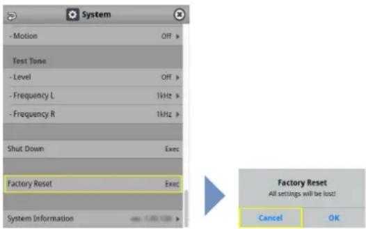
* If you decide to cancel, press the [EXIT] button.
2. Use the [VALUE] knob to select "OK", and then press the [VALUE] knob.
Factory reset is executed. When the operation is finished, the message "Completed" appears.
Remotely Controlling the VR-120HD
To remotely control the VR-120HD, you can use an external device to send control signals to the unit (p. 95), use a dedicated app, or use LAN/RS-232 commands.
MEMO
The dedicated apps "VR-120HD RCS" and "VR-120HD Remote" are planned to be updated for compatibility with this unit.
Using the dedicated apps "VR-120HD RCS" and "VR-120HD Remote"
Dedicated apps are available for computers ("VR-120HD RCS") and for the iPad ("VR-120HD Remote").
These apps can be downloaded from the Roland website.
https://proav.roland.com/
* For details on operation, refer to the Owner's Manual of "VR-120HD RCS" or "VR-120HD Remote".
VR-120HD RCS (Windows/Mac)
Use the dedicated "VR-120HD RCS" app to operate the VR-120HD from your computer.
You can connect either wirelessly or via cable.
Wireless connection
- Connection via wireless LAN master device (Wi-Fi)
Wired connection (via cable)
•USB connection (USB Type-C cable)
• LAN connection (LAN cable)
•RS-232 connection (RS-232 cable)
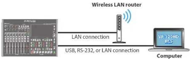
flowchart
graph LR
    A["Computer"] -->|USB, RS-232, or LAN connection| B["Wireless LAN router"]
    B -->|LAN connection| A
    B --> C["VR-120HD RCS"]
VR-120HD Remote
Use the dedicated "VR-120HD Remote" app to operate the VR-120HD from your iPad.
You can connect either wirelessly or via cable.
Wireless connection
- Bluetooth connection
- Connection via wireless LAN master device (Wi-Fi)
Wired connection (via cable)
USB connection (USB Type-C cable, Lightning to USB camera adapter)

flowchart
graph LR
    A["Wireless LAN router"] -->|LAN connection| B["VR-120HD Remote"]
    A -->|USB connection| C["Bluetooth connection"]
    A -->|USB connection| D["iPad"]
LAN/RS-232 command
The VR-120HD support two types of remote-interface communication: LAN and RS-232.
Using the DIRECT STREAM port or RS-232 connector to send specific commands to the VR-120HD from a controlling device lets you operate the VR-120HD.
See "Remote Control Guide" (PDF) for details on each interface and for a list of LAN/RS-232 commands.
https://roland.cm/vr-120hd
MEMO
MIDI implementation
The VR-120HD supports MIDI remote control.
See "MIDI Implementation" in the "Remote Control Guide" (PDF) for details.
1: Video Assign
| Menu item Value (bold text: default value) Explanation | |||
| Jump To Setup Enter Jumps to the setup screen. | |||
| Input 1-8 | HDMI 1-6, SDI 1-6, Still 1-16, V.Player, Stream/Record Status 1-2, Date&Time (Analog/Digital (*)), N/AThe default values are as follows.Input 1:HDMI 1Input 2:HDMI 2Input 3:HDMI 3Input 4:HDMI 4Input 5:HDMI 5Input 6:HDMI 6Input 7:Still 1Input 8:Still 2 | Sets the video source (input video and still images) to assign to the VIDEO SWITCHER [1]-[8] buttons.(*) The analog/digital display changes in the "System→ Date&Time → Clock Display Type" setting. | |
| HDMI Out 1-3 | Specifies the video bus that is assigned to the HDMI OUT 1-3 connectors. | ||
| Program | Final output video. This is the default setting for "HDMI Out 1". | ||
| Sub Program | Sub Program bus video | ||
| Preview | Preview output video. This is the default setting for "HDMI Out 2". | ||
| AUX AUX bus video | |||
| Multi-View Multi-view. This is the default setting for "HDMI Out 3". | |||
| Input-View | The input video from the HDMI IN and SDI IN connectors (shown as 16 separate sections on the screen) | ||
| Still-View Still images loaded into the unit (shown as 16 separate sections on the screen) | |||
| SDI Out 1-3 | Specifies the video bus that is assigned to the SDI OUT 1-3 connectors. | ||
| Program Final output video. This is the default setting for "SDI Out 1". | |||
| Sub Program SUB PROGRAM bus video | |||
| Preview Preview output video. This is the default setting for "SDI Out 2". | |||
| AUX AUX bus video | |||
| Multi-View Multi-view. This is the default setting for "SDI Out 3". | |||
| Input-View | The input video from the HDMI IN and SDI IN connectors (shown as 16 separate sections on the screen) | ||
| Still-View Still images loaded into the unit (shown as 16 separate sections on the screen) | |||
| USB Out | Specifies the video bus that is assigned to the USB STREAM port. | ||
| Program Final output video. | |||
| Sub Program SUB PROGRAM bus video | |||
| Preview Preview output video. | |||
| AUX AUX bus video | |||
| Multi-View | Multi-view. | ||
| Input-View | The input video from the HDMI IN and SDI IN connectors (shown as 16 separate sections on the screen) | ||
| Still-View Still images loaded into the unit (shown as 16 separate sections on the screen) | |||
| Stream/Record | Specifies the video bus that is assigned to the DIRECT STREAM port. | ||
| Program Final output video. | |||
| Sub Program SUB PROGRAM bus video | |||
| Preview Preview output video. | |||
| AUX AUX bus video | |||
| Multi-View | Multi-view. | ||
| Input-View | The input video from the HDMI IN and SDI IN connectors (shown as 16 separate sections on the screen) | ||
| Still-View Still images loaded into this unit (shown as 16 separate sections on the screen) | |||
| LCD Monitor | Specifies the video bus to which this unit's display is assigned. | ||
| Program Final output video. | |||
| Sub Program SUB PROGRAM bus video | |||
| Preview Preview output video. | |||
| AUX AUX bus video | |||
| Multi-View Multi-view. | |||
| Input-View | The input video from the HDMI IN and SDI IN connectors (shown as 16 separate sections on the screen) | ||
| Still-View Still images loaded into the unit (shown as 16 separate sections on the screen) | |||
| AUX Source | HDMI 1–6, SDI 1–6, Still 1–16, V.Player, Input 1–8 | Selects the video that is sent to the AUX bus.When "AUX" is selected on the [MODE] button, you can use the VIDEO SWITCHER [1]–[8] buttons to select the video that is sent to the AUX bus. | |
| Program Layer | Enter Displays the Program Layer menu. | ||
| Menu item Value Explanation | |||
| PinP & KEY 1–4 | Disable, Enable | Sets whether each layer is displayed (Enable) or hidden (Disable) in the final output video. | |
| DSK 1, 2 | Disable, Enable | ||
| Sub Program Layer | Enter Displays the Sub Program Layer menu. | ||
| Menu item Value Explanation | |||
| PinP & KEY 1–4 Disable, Enable | Sets whether each layer is displayed (Enable) or hidden (Disable) in the Sub Program bus video. | ||
| DSK 1, 2 Disable, Enable | |||
| AUX Layer | Enter Displays the AUX Layer menu. | ||
| Menu item Value Explanation | |||
| PinP & KEY 1–4 Off, PGM Sync, On | Sets whether each layer in the AUX bus video is shown (On), synced with PGM (PGM Sync) or hidden (Off). | ||
| DSK 1, 2 Off, PGM Sync, On | |||
2: Video Input
| Menu item Value (bold text: default value) Explanation | ||
| HDMI In 1-6 (SCALER) Adjusts the video that is input from the HDMI IN 1-6 connectors. | ||
| Input Status Enter Displays information about the incoming video (format, size, etc.). | ||
| Flicker Filter OFF, ON When this is "ON", flickering is reduced. | ||
| Flip H | OFF, ON | When this is "ON", the video is input with left and right flipped. |
| Flip V | OFF, ON | When this is "ON", the video is input with top and bottom flipped. |
| EDID (*1) | InternalSVGA (800 x 600)XGA (1024 x 768)WXGA (1280 x 800)FWXGA (1366 x 768)SXGA (1280 x 1024)SXGA+ (1400 x 1050)UXGA (1600 x 1200)WUXGA (1920 x 1200)720p, 1080i, 1080p | Specifies the input format (EDID).When this is "INTERNAL", EDID information for all formats that can be input to the VR-120HD will be transmitted.What is EDID?EDID is data that is transmitted from the VR-120HD to the source device when the VR-120HD is connected to a source device. EDID contains data such as the formats that can be input to the VR-120HD (resolution, color space, color depth) and audio information. Based on the EDID information that the source device receives, it will output the most appropriate video format to the VR-120HD. |
| Zoom 10.0-100.0-1000.0% (*2) Adjusts the zoom ratio. | ||
| Scaling Type | Specifies the scaling type. | |
| Full | Always displays the picture expanded to full screen, irrespective of the aspect ratio of the input video. | |
| Letterbox | Enlarges or reduces the incoming video to a full-screen view while keeping the aspect ratio unchanged. | |
| Crop | Enlarges or reduces the incoming video so that the output picture has no blank margins while keeping the aspect ratio unchanged. Video extending beyond the borders is cut off. | |
| Dot By Dot Performs no scaling. | ||
| Manual | Scale according to the "Manual Size H" and "Manual Size V" settings below. | |
| Manual Size H (*3) | -2000-0-2000 (*2) | Adjusts the horizontal size. |
| Manual Size V (*3) | -2000-0-2000 (*2) | Adjusts the vertical size. |
| Position H | -1920-0-1920 | Adjusts the position in the horizontal direction. |
| Position V | -1200-0-1200 | Adjusts the position in the vertical direction. |
| Brightness | -32-0-31 | Adjusts the brightness. |
| Contrast | -32-0-31 | Adjusts the contrast. |
| Saturation | -32-0-31 | Adjusts the saturation. |
| Red | -64-0-63 | Adjusts the red level. |
| Green | -64-0-63 | Adjusts the green level. |
| Blue | -64-0-63 | Adjusts the blue level. |
| SDI In 1-6 Adjusts the video that is input from the SDI IN 1-6 connectors. | ||
| Input Status Enter Displays information about the incoming video (format, size, etc.). | ||
| Flip H | OFF, ON | When this is "ON", the video is input with left and right flipped. |
| Flip V | OFF, ON | When this is "ON", the video is input with top and bottom flipped. |
| Brightness | -32-0-31 | Adjusts the brightness. |
| Contrast | -32-0-31 | Adjusts the contrast. |
| Saturation | -32-0-31 | Adjusts the saturation. |
| Video Player Adjusts the video that is input from the video player. | ||
| Flip H | OFF, ON | When this is "ON", the video is input with left and right flipped. |
| Flip V | OFF, ON | When this is "ON", the video is input with top and bottom flipped. |
(*1) A change in the setting is not applied until you press the [VALUE] knob to confirm.
(*2) The valid range of setting values depends on conditions such as the input/output format.
(*3) This can be set if "Scaling Type" Is "Manual".
3: Video Output
| Menu item Value (bold text: default value) Explanation | ||
| HDMI Out 1-3 Adjusts the video that is output from the HDMI OUT 1-3 connectors. | ||
| Output Status — | Shows the format and an HDCP signal presence. If there is no connection, "Not Connected" is shown. | |
| Color Space | YPbPr (4: 4: 4), YPbPr (4: 2: 2), RGB (0-255), RGB (16-235) | Specifies the color space. |
| DVI-D/HDMI Signal HDMI, DVI-D Specifies the type of output signal. | ||
| Brightness -64-0-63 Adjusts the brightness. | ||
| Contrast -64-0-63 Adjusts the contrast. | ||
| Saturation -64-0-63 Adjusts the saturation. | ||
| Red -64-0-63 Adjusts the red level. | ||
| Green -64-0-63 Adjusts the green level. | ||
| Blue -64-0-63 Adjusts the blue level. | ||
| External Rec Control | OFF, ON | Turns the External Rec control on/off. When this is "ON", REC START/STOP commands can be sent to a recorder that supports REC control functionality.To use the External Rec control function, the REC START/STOP functions must be assigned to the USER button. From the System menu → "User Assign" → "User 1"- "User 4" set "Category" to "External Rec Control". |
| SDI Out 1-3 | Adjusts the video that is output from the SDI OUT 1-3 connectors. | |
| Output Status — | Shows the format.* When "HDCP" in the SYSTEM menu is "ON", "HDCP MASKED" is displayed, and video/audio is not outputted from the SDI OUT connectors. | |
| 3G-SDI Mapping | Level-A, Level-B | Specifies the mapping structure of the 3G-SDI output. |
| Brightness -64-0-63 Adjusts the brightness. | ||
| Contrast -64-0-63 Adjusts the contrast. | ||
| Saturation -64-0-63 Adjusts the saturation. | ||
| USB Out | Adjusts the video that is output from the USB STREAM port.* You can edit the USB output video format and compression method from the livestreaming app or other app used at the output destination. | |
| Output Status — | Indicates whether the connection uses USB 2.0 (HIGH SPEED) or USB 3.0 (SUPER SPEED). If not connected to a computer, this indicates "Not Connected"* When "HDCP" in the SYSTEM menu is "ON", "HDCP MASKED" is displayed, and video/audio is not outputted from the USB STREAM port. | |
| Output Format | Sets the output destination formats that can be selected from the livestreaming app. | |
| YUY2 & MJPEG | YUY2 and Motion JPEG are selectable. | |
| YUY2 | Only YUY2 is selectable. | |
| Connection Reset | Exec | Reconnects the computer and the VR-120HD when the video is garbled or when operation is otherwise unstable. |
4: Transition
| Menu item Value (bold text: default value) Explanation | ||
| Mix These are the detailed mix settings. | ||
| Jump To Setup Enter Jumps to the setup screen. | ||
| Mix Type | Specifies the transition pattern for mix. | |
| Mix The two videos are mixed as the transition occurs. | ||
| Fam | Video transitions are made with the luminance levels of the two video streams maintained unchanged. This is an abbreviation of "full additive mix". | |
| Nam | The two video streams are compared, and transitions are made with display during transition starting with levels of high luminance. This is an abbreviation of "non-additive mix". | |
| Mix Time 0.0-1.0-4.0sec | Specifies the video transition time. | |
| Wipe These are the detailed wipe settings. | ||
| Jump To Setup Enter Jumps to the setup screen. | ||
| Wipe Type | Specifies the transition pattern for wipe. | |
        | ||
| Wipe Time | 0.0-1.0-4.0sec | Specifies the video transition time. |
| Direction | Normal, Reverse, Round Trip | Specifies the direction of wipe. |
| Border Color | White, Yellow, Cyan, Green, Magenta, Red, Blue, Black, Soft Edge | Specifies the color of the border added to the edge of the wipe area. When this is set to "Soft Edge", the wipe border is blurred. |
| Border Width | 0-3-14 | Specifies the width of the border added to the edge of the wipe area. |
| Split 1, 2 These are the detailed settings for the split composite. | ||
| Jump To Setup Enter Jumps to the setup screen. | ||
| Split Type | These parameters configure the split screen layout. | |
| Split V | This vertically crops the center section of the video (split left/right). This is the default setting for "Split 1".A+BAB | |
| Split H | This horizontally crops the center section of the video (split upper/lower). This is the default setting for "Split 2".A+BAB | |
| PGM Source | HDMI 1-6, SDI 1-6, Still 1-16, V.Player, Input 1-8 | Selects the video source to display on the left or upper side. |
| PST Source | HDMI 1-6, SDI 1-6, Still 1-16, V.Player, Input 1, Input 2-8 | Selects the video source to display on the left or upper side. |
| PGM Center | -50.0-0.0-50.0% | When at SPLIT VAdjusts the horizontal position of the video placed on the left.When at SPLIT HAdjusts the horizontal position of the video placed above.* This positions the PGM bus video to the left or upper side. |
| PST Center | -50.0-0.0-50.0% | When at SPLIT VAdjusts the horizontal position of the video placed on the right.When at SPLIT HAdjusts the horizontal position of the video placed below.* This positions the PST bus video to the right or lower side. |
| Center Position | -50.0-0.0-50.0% | Adjusts the position of the boundary. |
| Border Color | White, Yellow, Cyan, Green, Magenta, Red, Blue, Black | Specifies the color of the border. |
| Border Width | 0-3-14 | Adjusts the width of the border. |
5: PinP & Key
| Menu item Value (bold text: default value) Explanation | ||
| PinP & Key 1-4 These are the detailed settings for PinP and key composition for each PinP and key layer. | ||
| Jump To Setup Enter Jumps to the setup screen. | ||
| Type | Specifies the type of PinP compositing. | |
| PinP | Composites the inset screen on top of the background video. | |
| Luminance-White Key | A combination of PinP and luminance key (white). Makes the white portions of the inset screen transparent, and composites the image with the background. | |
| Luminance-Black Key | A combination of PinP and luminance key (black). Makes the black portions of the inset screen transparent, and composites the image with the background. | |
| Chroma Key | A combination of PinP and chroma key. Makes the specified key color portions of the inset screen transparent, and composites the image with the background. | |
| Source | HDMI 1-6, SDI 1-6, Still 1-16, VPlayer, Input 1-8 | Specifies the video source of the inset screen. |
| Time 0.0-1.0-4.0sec Specifies the video transition time. | ||
| When Type = PinP | ||
| Window Adjusts the inset screen. | ||
| Position H | -50.0--40.0-50.0% | Adjusts the horizontal position of the inset screen. |
| Position V | -50.0--40.0-50.0% | Adjusts the vertical position of the inset screen. |
| Size | 0.0-35.0-100.0% | Adjusts the size of the inset screen. |
| Cropping H | 0.0-100.0% | Adjusts the horizontal size of the inset screen. |
| Cropping V | 0.0-100.0% | Adjusts the vertical size of the inset screen. |
| Shape | Rectangle, Circle, Diamond | Specifies the shape of the inset screen. |
| Border Color | White, Yellow, Cyan, Green, Magenta, Red, Blue, Black, Soft Edge | Specifies the color of the border for the inset screen. When this is set to "Soft Edge", the edge of the inset screen is blurred. |
| Border Width | 0-3-14 | Adjusts the width of the border for the inset screen. |
| View | Adjusts the video that is shown in the inset screen. | |
| Position H | -50.0-0.0-50.0% | Adjusts the horizontal position at which the inset screen is shown. |
| Position V | -50.0-0.0-50.0% | Adjusts the vertical position at which the inset screen is shown. |
| Zoom | 100-400% | Adjusts the zoom of the video shown in the inset screen. |
| When Type = Luminance-White Key or Luminance-Black Key | ||
| Window Adjusts the inset screen. | ||
| Position H | -50.0--40.0-50.0% | Adjusts the horizontal position of the inset screen. |
| Position V | -50.0--40.0-50.0% | Adjusts the vertical position of the inset screen. |
| Size | 0.0-35.0-100.0 % | Adjusts the size of the inset screen. |
| Cropping H | 0.0-100.0% | Adjusts the horizontal size of the inset screen. |
| Cropping V | 0.0-100.0% | Adjusts the vertical size of the inset screen. |
| View | Adjusts the video that is shown in the inset screen. | |
| Position H | -50.0-0.0-50.0% | Adjusts the horizontal position at which the inset screen is shown. |
| Position V | -50.0-0.0-50.0% | Adjusts the vertical position at which the inset screen is shown. |
| Zoom | 10O-400% | Adjusts the zoom of the video shown in the inset screen. |
| Key | Adjusts the key. | |
| Key Level | 0-64-255 | Adjusts the degree of extraction (transparency) for the key. |
| Key Gain | 0-255 | Adjusts the degree of edge blur (semi-transmissive region) for the key. |
| Mix Level | 0-255 | Adjusts the key's overall density (output level). |
| When Type = Chroma Key | ||
| Window Adjusts the inset screen. | ||
| Position H | -50.0--40.0--50.0% Adjusts the horizontal position of the inset screen. | |
| Position V | -50.0--40.0--50.0% Adjusts the vertical position of the inset screen. | |
| Size | 0.0--35.0--100.0% Adjusts the size of the inset screen. | |
| Cropping H | 0.0--100.0% Adjusts the horizontal size of the inset screen. | |
| Cropping V | 0.0--100.0% Adjusts the vertical size of the inset screen. | |
| View Adjusts the video that is shown in the inset screen. | ||
| Position H | -50.0--0.0--50.0% Adjusts the horizontal position at which the inset screen is shown. | |
| Position V | -50.0--0.0--50.0% Adjusts the vertical position at which the inset screen is shown. | |
| Zoom | 100--400% Adjusts the zoom of the video shown in the inset screen. | |
| Key Adjusts the key. | ||
| Key Level | 0--64--255 | Adjusts the degree of extraction (transparency) for the key. |
| Key Gain | 0--255 | Adjusts the degree of edge blur (semi-transmissive region) for the key. |
| Mix Level | 0--255 | Adjusts the key's overall density (output level). |
| Chroma Make detailed settings for chroma key. | ||
| Color | Green, Blue | Specifies green or blue as the key color (the color to be removed). If you want a color other than green or blue to turn transparent, use "Sampling Marker Mode" to specify the key color. |
| Hue Width | -30--0--30 Adjusts the hue width for the key color. | |
| Hue Fine | 0--240--360 Adjusts the center position of the hue for the key color. | |
| Saturation Width | -128--0--127 | Adjusts the saturation width for the key color. |
| Saturation Fine | 0--255 | Adjusts the center position of saturation for the key color. |
6: DSK
| Menu item Value (bold text: default value) Explanation | ||
| DSK 1,2 These settings configure the DSK composite details for each DSK layer. | ||
| Jump To Setup Enter Jumps to the setup screen. | ||
| DSK Mode | Sets the DSK mode. | |
| Self Key | Uses the luminance key (brightness) and chroma key (color) to cut out the video image and create a composite by overlaying the video on a background video. | |
| Alpha Key | Uses alpha channels (areas which contain transparency data) to cut out still images and place them against different background video as a composite. | |
| External Key | Sets the key signal (the shape to be cut out) and the fill video (the video to be composited) separately (external key). This uses the key signal to cut out the fill video and superimpose it on the background video to create the composite. | |
| DSK Source | HDMI 1-6, SDI 1-6, Still 1-2-16, V.Player, Input 1-8* When DSK Mode = Self KeyStill 1-2-16* When DSK Mode = Alpha Key | Specifies the source of the caption or video that is overlaid. |
| Key Source (*4) | HDMI 1-6, SDI 1-6, Still 1-2-16, V.Player, Input 1-8 | Sets the video to use as the key signal (the shape to be cut out).* Sets the default value to "HDMI 5-6" when you long-press the [VALUE] knob while DSK Mode = "External Key". |
| Fill Source (*4) | HDMI 1-6, SDI 1-6, Still 1-2-16, V.Player, Input 1-8 | Specifies the fill video (the video to be composited) source.* Sets the default value to "HDMI 5-6" when you long-press the [VALUE] knob while DSK Mode = "External Key". |
| DSK Time | 0.0-1.0-4.0sec | Specifies the video transition time. |
| DSK Type (*5) | Specifies the DSK type used during DSK composition. | |
| Luminance-White Key | Composite using luminance key.Makes white portions transparent according to brightness. | |
| Luminance-Black Key | Composite using luminance key.Makes black portions transparent according to brightness. | |
| Chroma Key | Composite using chroma key.Makes the specified key color transparent according to hue. | |
| DSK Level (*5) | 0-64-255 | Adjusts the degree of extraction (transparency) for the key. |
| DSK Gain (*5) | 0-255 | Adjusts the degree of edge blur (semi-transmissive region) for the key. |
| Mix Level | 0-255 | Adjusts the key's overall density (output level). |
| Chroma (*6) | Make detailed settings for chroma key. | |
| Color | Green, Blue | Specifies green or blue as the key color. If you want a color other than green or blue to turn transparent, use "Sampling Marker Mode" to specify the key color. |
| Hue Width | -30-0-30 | Adjusts the hue width for the key color. |
| Hue Fine | 0-240-360 | Adjusts the center position of the hue for the key color. |
| Saturation Width | -128-0-127 | Adjusts the saturation width for the key color. |
| Saturation Fine | 0-255 | Adjusts the center position of saturation for the key color. |
| Fill Type | Sets the fill material type (the video used for key compositing). | |
| Bus | Uses the video specified in "DSK Source". | |
| Matte | Uses the internal color matte (a single-color image). The superimposed caption or video is filled in with the matte color. Specify the matte color using the "Matte Color" setting below. | |
| Matte Color (*7) | White, Yellow, Cyan, Green, Magenta, Red, Blue, Black | Specifies the matte color. |
| Edge Type | Off, Border, Drop, Shadow, Outline | Specifies the type of edge applied to the superimposed caption or video. |
| Edge Color | White, Yellow, Cyan, Green, Magenta, Red, Blue, Black | Specifies the color of the edge applied to the superimposed caption or video. |
| Edge Width | 0-3-14 | Specifies the width of the edge applied to the superimposed caption or video. |
(*4) This can be set if "DSK Mode" is "External Key".
(*5) This can be set if "DSK Mode" is "Self Key".
(*6) This can be set if "DSK Type" is "Chroma Key".
(*7) This can be set if "Fill Type" is "Matte".
7: Audio Fader Assign
| Menu item Value (bold text: default value) Explanation | ||
| Jump To Setup Enter Jumps to the setup screen. | ||
| Input Fader 1–9/10 | Audio In 1–9/10, USB In, Bluetooth In, Audio Player, HDMI 1–6, SDI 1–6, V.PlayerThe default values are as follows.Input Fader 1:Audio In 1Input Fader 2:Audio In 2Input Fader 3:Audio In 3Input Fader 4:Audio In 4Input Fader 5:Audio In 5Input Fader 6:Audio In 6Input Fader 7/8:Audio In 7/8Input Fader 9/10:Audio In 9/10 | Selects the audio input to assign to each fader. |
8: Audio Input
| Menu item Value (bold text) | default value) Explanation | |
| Audio In 1,2Audio In 1/2 (Linked) | Adjusts the audio that is input from the AUDIO IN 1 and 2 jacks.* "Audio In 1/2 (Linked)" is shown when "Stereo Link" is "ON". | |
| Jump To Setup Enter Jumps to the setup screen. | ||
| Analog Gain | 0-68dB | Adjusts the input gain (sensitivity) in the analog domain. |
| Digital Gain | -42.0-0.0-42.0dB | Adjusts the input gain (sensitivity) in the digital domain (after conversion from analog to digital). |
| Input Level | -INF-0.0-10.0dB | Adjusts the input volume.This can also be adjusted by the [1] or [2] fader. (*8) |
| Input Mute | OFF, ON | Turns the mute function on/off. When this is "ON", the input audio is temporarily silenced. |
| Phantom +48V | OFF, ON | Turns the phantom power on/off. When this is "ON", phantom power is supplied via the AUDIO IN jacks (XLR).* Changing "Stereo Link" settings automatically turns "Phantom +48V" settings "OFF". |
| Pan (*9) | Left-Center-Right | Adjusts the stereo position (pan). |
| Stereo Link | OFF, ON | Turns the stereo link function on/off. When this is "ON", Audio In 1 and 2 are linked, and operate as a stereo channel.* When stereo link is turned on, the settings of Audio In 1 are applied to Audio In 2. |
| Solo | OFF, ON | Turns the solo function on/off. Only the audio for which this is "ON" is heard in the headphones.* The solo function applies to the headphone output. It does not affect output other than the headphones. |
| Delay | 0.0-500msec(0-25.0/29.9/30.0frame) | Adjusts the delay time of the audio.Effect Outputs audio with a delay. |
| Reverb Send | 0-127 Adjusts the amount of audio sent to reverb. | |
| Main Bus | This configures the Main bus. | |
| Send | OFF, ON When this is "ON", audio is sent to the Main bus. | |
| AUX 1 Bus | This configures the AUX 1 bus. | |
| Send Level | -INF-10.0dB These parameters adjust | the amount of audio sent to the AUX 1 bus. |
| Send Point | Dry | Sends the source audio with no effects applied. |
| Pre Fader | Sends the effect-applied audio.The send volume is constant, regardless of the volume (Input Level). | |
| Post Fader | Sends the effect-applied audio.The send volume can be changed by adjusting the volume (Input Level). | |
| AUX 2 Bus | This configures the AUX 2 bus. | |
| Send Level | -INF-10.0dB These parameters adjust | the amount of audio sent to the AUX 2 bus. |
| Send Point | Dry | Sends the source audio with no effects applied. |
| Pre Fader | Sends the effect-applied audio.The send volume is constant, regardless of the volume (Input Level). | |
| Post Fader | Sends the effect-applied audio.The send volume can be changed by adjusting the volume (Input Level). | |
| High Pass Filter 80Hz | OFF, ON | Turns the high-pass filter on/off.Effect Cuts off unneeded low-band audio. The cutoff frequency is 80 Hz. |
| Echo Canceller | OFF, ON | Turns the echo canceller on/off.Effect Suppresses the voice echo that can occur when using a web conferencing system that includes a speaker and mic. |
| Depth | 1-5-10 Adjusts the depth of the echo canceller. | |
| Anti Feedback | OFF, ON | Turns the anti-feedback on/off.Effect Suppresses audio feedback. |
| Noise Gate | OFF, ON | Turns the noise gate on/off.Effect Eliminates audio that is lower than the specified threshold level. This is effective when the noise that you want to remove is separate from the audio that you want to keep, and can be used to remove hiss or other noise that is heard during periods of silence. |
| Threshold | -80--48-0dB | Specifies the level used as the threshold for removing audio. Audio below the level set here is removed. |
| Release | 30-500-5000msec | Adjusts the length of time until the audio is fully attenuated after audio falls below the threshold. |
| De-Esser | OFF, ON | Turns the de-esser on/off.Effect Reduces sibilant noise (the sounds you hear when pronouncing "s" words and other hissing sounds). |
| Menu item Value (bold text: default value) Explanation | ||
| Sens | 0-80-100 | Adjusts the sensitivity with which sibilants are detected. |
| Depth | 0-64-100 | Adjusts the intensity of the effect. |
| Compressor | OFF, ON | Turns the compressor on/off.EffectAudio that exceeds the specified threshold level is compressed. This reduces the difference between the maximum volume and minimum volume, making the audio more comfortable for listening. |
| Threshold | -50--8-0dB | Specifies the level used as the threshold at which the compressor is applied.Compression is applied to audio that exceeds the threshold. |
| Ratio | 1.00: 1, 1.12: 1, 1.25: 1, 1.40: 1,1.60: 1, 1.80: 1, 2.00: 1,2.50: 1,3.20: 1, 4.00: 1, 5.60: 1, 8.00: 1,16.0: 1, INF: 1 | Specifies the degree of compression applied to the audio. The state in which no compression is applied is defined as "1". |
| Attack | 0.0-30-100msec | Specifies the time until compression starts when audio exceeding the threshold is input. |
| Release | 30-250-5000msec | Adjusts the length of time until compression ends after audio falls below the threshold. |
| Makeup Gain | -40-0-40dB | Adjusts the final output volume level after applying the compressor. |
| Equalizer OFF, ON | Turns the equalizer on/off.EffectThis is a 4-band parametric equalizer. It lets you shape the character of the sound by boosting or cutting four frequency regions. | |
| Hi Gain -12.0-0.0-12.0dB | Boosts or attenuates the high band. | |
| Hi Freq | 1.00-10.0-20.0kHz | Adjusts the center frequency when changing the tone quality in the high band. |
| Hi-Mid Gain | -12.0-0.0-12.0dB | Boosts or attenuates the high-midrange band. |
| Hi-Mid Freq 20.0Hz-2.00kHz-20.0kHz | Adjusts the center frequency when changing the tone quality in the high-midrange band. | |
| Hi-Mid Q 0.5-1.0-16.0 | Adjusts the width of the frequency band when boosting or attenuating high-midrange band. | |
| Lo-Mid Gain | -12.0-0.0-12.0dB | Boosts or attenuates the low-midrange band. |
| Lo-Mid Freq | 20.0Hz-500Hz-20.0kHz | Adjusts the center frequency when changing the tone quality in the low-midrange band. |
| Lo-Mid Q 0.5-1.0-16.0 | Adjusts the width of the frequency band when boosting or attenuating low-midrange band. | |
| Lo Gain | -12.0-0.0-12.0dB | Boosts or attenuates the low band. |
| Lo Freq | 20.0Hz-100Hz-2.00kHz | Adjusts the center frequency when changing the tone quality in the low band. |
| Voice Changer | OFF, ON | Turns the voice changer on/off.EffectTransforms the pitch or character of the voice. |
| Pitch | -12-+12 | Adjusts the pitch of the voice in semitone steps. A setting of "0" is the original pitch. |
| Formant | -10-+4-+10 | Adjusts the character (formant) of the voice. Settings in the negative (-) direction produce a more masculine vocal character, and settings in the positive (+) direction produce a more feminine vocal character. A setting of "0" is the original voice. |
| Robot | OFF, ON | If this is "ON", the voice is held at a fixed pitch, creating a mechanical robot-like impression. |
| Mix 0-100 | Adjusts the balance between the unprocessed voice (0) and the voice processed by the effect (100). | |
(*8) The [2] fader is disabled when "Stereo Link" is "ON".
(*9) This can be set if "Stereo Link" is "OFF".
| Menu item Value (bold text default value) Explanation | ||
| Audio In 3-6Audio In 3/4 (Linked),Audio In 5/6 (Linked) | Adjusts the audio that is input from the AUDIO IN 3-6 jacks.* "Audio In 3/4 (Linked)" "Audio In 5/6 (Linked)" is shown when "Stereo Link" is "ON". | |
| Jump To Setup Enter Jumps to the setup screen. | ||
| Analog Gain | 0-68db | Adjusts the input gain (sensitivity) in the analog domain. |
| Digital Gain | -42.0-0.0-42.0dB | Adjusts the input gain (sensitivity) in the digital domain (after conversion from analog to digital). |
| Input Level | -INF-0.0-10.0dB | Adjusts the input volume.This can also be adjusted by the [3]-[6] fader. (*10) |
| Input Mute | OFF, ON | Turns the mute function on/off. When this is "ON", the input audio is temporarily silenced. |
| Phantom +48V | OFF, ON | Turns the phantom power on/off. When this is "ON", phantom power is supplied via the AUDIO IN jacks (XLR).* Changing "Stereo Link" settings automatically turns "Phantom +48V" settings "OFF". |
| Pan (*11) | Left-Center-Right | Adjusts the stereo position (pan). |
| Stereo Link | OFF, ON | Turns the stereo link function on/off. When this is "ON", Audio In 3 and 4 (5 and 6) are linked, and operate as a stereo channel.* When stereo link is turned on, the settings of Audio In 3 (5) are applied to Audio In 4 (6). |
| Solo | OFF, ON | Turns the solo function on/off. Only the audio for which this is "ON" is heard in the headphones.* The solo function applies to the headphone output. It does not affect output other than the headphones. |
| Delay | 0.0-500msec(0-25.0/29.9/30.0frame) | Adjusts the delay time of the audio.Effect Outputs audio with a delay. |
| Reverb Send | 0-127 Adjusts the amount of audio sent to reverb. | |
| Main Bus | This configures the Main bus. | |
| Send | OFF, ON When this is "ON", audio is sent to the Main bus. | |
| AUX 1 Bus | This configures the AUX 1 bus. | |
| Send Level | -INF-10.0dB These parameters adjust | the amount of audio sent to the AUX 1 bus. |
| Send Point | Dry | Sends the source audio with no effects applied. |
| Pre Fader | Sends the effect-applied audio.The send volume is constant, regardless of the volume (Input Level). | |
| Post Fader | Sends the effect-applied audio.The send volume can be changed by adjusting the volume (Input Level). | |
| AUX 2 Bus | This configures the AUX 2 bus. | |
| Send Level | -INF-10.0dB These parameters adjust | the amount of audio sent to the AUX 2 bus. |
| Send Point | Dry | Sends the source audio with no effects applied. |
| Pre Fader | Sends the effect-applied audio.The send volume is constant, regardless of the volume (Input Level). | |
| Post Fader | Sends the effect-applied audio.The send volume can be changed by adjusting the volume (Input Level). | |
| High Pass Filter 80Hz | OFF, ON | Turns the high-pass filter on/off.Effect Cuts off unneeded low-band audio. The cutoff frequency is 80 Hz. |
| Noise Gate | OFF, ON | Turns the noise gate on/off.Effect Eliminates audio that is lower than the specified threshold level. This is effective when the noise that you want to remove is separate from the audio that you want to keep, and can be used to remove hiss or other noise that is heard during periods of silence. |
| Threshold | -80--48-0dB | Specifies the level used as the threshold for removing audio. Audio below the level set here is removed. |
| Release | 30-500-5000msec | Adjusts the length of time until the audio is fully attenuated after audio falls below the threshold. |
| De-Esser | OFF, ON | Turns the de-esser on/off.Effect Reduces sibilant noise (the sounds you hear when pronouncing "s" words and other hissing sounds). |
| Sens | 0-80-100 | Adjusts the sensitivity with which sibilants are detected. |
| Depth | 0-64-100 | Adjusts the intensity of the effect. |
| Compressor | OFF, ON | Turns the compressor on/off.Effect Audio that exceeds the specified threshold level is compressed. This reduces the difference between the maximum volume and minimum volume, making the audio more comfortable for listening. |
| Threshold | -50--8-0dB | Specifies the level used as the threshold at which the compressor is applied.Compression is applied to audio that exceeds the threshold. |
| Menu item Value (bold text) | default value) Explanation | |
| Ratio | 1.00: 1, 1.12: 1, 1.25: 1, 1.40: 1,1.60: 1, 1.80: 1, 2.00: 1,2.50: 1,3.20: 1, 4.00: 1, 5.60: 1, 8.00: 1,16.0: 1, INF: 1 | Specifies the degree of compression applied to the audio. The state in which no compression is applied is defined as "1". |
| Attack | 0.0–30–100msec | Specifies the time until compression starts when audio exceeding the threshold is input. |
| Release | 30–250–5000msec | Adjusts the length of time until compression ends after audio falls below the threshold. |
| Makeup Gain | -40–0–40dB | Adjusts the final output volume level after applying the compressor. |
| Equalizer OFF, ON | Turns the equalizer on/off.Effect This is a 4-band parametric equalizer. It lets you shape the character of the sound by boosting or cutting four frequency regions. | |
| Hi Gain -12.0–0.0–12.0dB | Boosts or attenuates the high band. | |
| Hi Freq | 1.00–10.0–20.0kHz | Adjusts the center frequency when changing the tone quality in the high band. |
| Hi-Mid Gain | -12.0–0.0–12.0dB | Boosts or attenuates the high-midrange band. |
| Hi-Mid Freq 20.0Hz–2.00kHz–20.0kHz | Adjusts the center frequency when changing the tone quality in the high-midrange band. | |
| Hi-Mid Q 0.5–1.0–16.0 | Adjusts the width of the frequency band when boosting or attenuating high-midrange band. | |
| Lo-Mid Gain | -12.0–0.0–12.0dB | Boosts or attenuates the low-midrange band. |
| Lo-Mid Freq | 20.0Hz–500Hz–20.0kHz | Adjusts the center frequency when changing the tone quality in the low-midrange band. |
| Lo-Mid Q 0.5–1.0–16.0 | Adjusts the width of the frequency band when boosting or attenuating low-midrange band. | |
| Lo Gain | -12.0–0.0–12.0dB | Boosts or attenuates the low band. |
| Lo Freq | 20.0Hz–100Hz–2.00kHz | Adjusts the center frequency when changing the tone quality in the low band. |
(*10) The [4] [6] fader is disabled when "Stereo Link" is "ON".
(*11) This can be set if "Stereo Link" is "OFF".
| Menu item Value (bold text default value) Explanation | ||
| Audio In 7/8, Audio In 9/10 Adjusts the audio that is input from the AUDIO IN 7/8 - 9/10 jacks. | ||
| Jump To Setup Enter Jumps to the setup screen. | ||
| Digital Gain | -42.0-0.0-42.0dB | Adjusts the input gain (sensitivity) in the digital domain (after conversion from analog to digital). |
| Input Level | -INF-0.0-10.0dB | Adjusts the input volume.This can also be adjusted by the [7/8]-[9/10] fader. (*10) |
| Input Mute | OFF, ON | Turns the mute function on/off. When this is "ON", the input audio is temporarily silenced. |
| Mono | Converts the input audio from stereo to mono. | |
| Off Sends the stereo input audio without change. | ||
| L Only The audio of the L channel is sent to both L and R. | ||
| R Only The audio of the R channel is sent to both L and R. | ||
| LR Mix The audio of the L channel and R channel is mixed, and sent to both L and R. | ||
| Solo | OFF, ON | Turns the solo function on/off. Only the audio for which this is "ON" is heard in the headphones.* The solo function applies to the headphone output. It does not affect output other than the headphones. |
| Delay | 0.0-500msec(0-25.0/29.9/30.0frame) | Adjusts the delay time of the audio.Effect Outputs audio with a delay. |
| Reverb Send | 0-127 Adjusts the amount of audio sent to reverb. | |
| Main Bus | This configures the Main bus. | |
| Send | OFF, ON When this is "ON", audio is sent to the Main bus. | |
| AUX 1 Bus | This configures the AUX 1 bus. | |
| Send Level | -INF-10.0dB | These parameters adjust the amount of audio sent to the AUX 1 bus. |
| Send Point | Dry | Sends the source audio with no effects applied. |
| Pre Fader | Sends the effect-applied audio.The send volume is constant, regardless of the volume (Input Level). | |
| Post Fader | Sends the effect-applied audio.The send volume can be changed by adjusting the volume (Input Level). | |
| AUX 2 Bus | This configures the AUX 2 bus. | |
| Send Level | -INF-10.0dB | These parameters adjust the amount of audio sent to the AUX 2 bus. |
| Send Point | Dry | Sends the source audio with no effects applied. |
| Pre Fader | Sends the effect-applied audio.The send volume is constant, regardless of the volume (Input Level). | |
| Post Fader | Sends the effect-applied audio.The send volume can be changed by adjusting the volume (Input Level). | |
| High Pass Filter 80Hz | OFF, ON | Turns the high-pass filter on/off.Effect Cuts off unneeded low-band audio. The cutoff frequency is 80 Hz. |
| Noise Gate | OFF, ON | Turns the noise gate on/off.Effect Eliminates audio that is lower than the specified threshold level. This is effective when the noise that you want to remove is separate from the audio that you want to keep, and can be used to remove hiss or other noise that is heard during periods of silence. |
| Threshold | -80--48-0dB | Specifies the level used as the threshold for removing audio. Audio below the level set here is removed. |
| Release | 30-500-5000msec | Adjusts the length of time until the audio is fully attenuated after audio falls below the threshold. |
| Compressor | OFF, ON | Turns the compressor on/off.Effect Audio that exceeds the specified threshold level is compressed. This reduces the difference between the maximum volume and minimum volume, making the audio more comfortable for listening. |
| Threshold | -50--8-0dB | Specifies the level used as the threshold at which the compressor is applied.Compression is applied to audio that exceeds the threshold. |
| Ratio | 1.00: 1, 1.12: 1, 1.25: 1, 1.40: 1, 1.60: 1, 1.80: 1, 2.00: 1, 2.50: 1, 3.20: 1, 4.00: 1, 5.60: 1, 8.00: 1, 16.0: 1, INF: 1 | Specifies the degree of compression applied to the audio. The state in which no compression is applied is defined as "1". |
| Attack | 0.0-30-100msec | Specifies the time until compression starts when audio exceeding the threshold is input. |
| Release | 30-250-5000msec | Adjusts the length of time until compression ends after audio falls below the threshold. |
| Makeup Gain | -40-0-40dB | Adjusts the final output volume level after applying the compressor. |
| Menu item Value (bold text) | default value) Explanation | |
| Equalizer OFF, ON | Turns the equalizer on/off. Effect This is a 4-band parametric equalizer. It lets you shape the character of the sound by boosting or cutting four frequency regions. | |
| Hi Gain -12.0-0.0-12.0dB | Boosts or attenuates the high band. | |
| Hi Freq | 1.00-10.0-20.0kHz | Adjusts the center frequency when changing the tone quality in the high band. |
| Hi-Mid Gain | -12.0-0.0-12.0dB | Boosts or attenuates the high-midrange band. |
| Hi-Mid Freq 20.0Hz-2.00kHz-20.0kHz | Adjusts the center frequency when changing the tone quality in the high-midrange band. | |
| Hi-Mid Q 0.5-1.0-16.0 | Adjusts the width of the frequency band when boosting or attenuating high-midrange band. | |
| Lo-Mid Gain | -12.0-0.0-12.0dB | Boosts or attenuates the low-midrange band. |
| Lo-Mid Freq | 20.0Hz-500Hz-20.0kHz | Adjusts the center frequency when changing the tone quality in the low-midrange band. |
| Lo-Mid Q 0.5-1.0-16.0 | Adjusts the width of the frequency band when boosting or attenuating low-midrange band. | |
| Lo Gain -12.0-0.0-12.0dB | Boosts or attenuates the low band. | |
| Lo Freq | 20.0Hz-100Hz-2.00kHz | Adjusts the center frequency when changing the tone quality in the low band. |
| USB In Adjusts the audio that is input from the USB STREAM port. | ||
| Jump To Setup Enter Jumps to the setup screen. | ||
| Digital Gain | -42.0-0.0-42.0dB | Adjusts the input gain (sensitivity) in the digital domain (after conversion from analog to digital). |
| Input Level | -INF-0.0-10.0dB | Adjusts the input volume.This can also be adjusted by the [7/8]-[9/10] fader. (*10) |
| Input Mute | OFF, ON | Turns the mute function on/off. When this is "ON", the input audio is temporarily silenced. |
| Mono | Converts the input audio from stereo to mono. | |
| Off Sends the stereo input audio without change. | ||
| L Only The audio of the L channel is sent to both L and R. | ||
| R Only The audio of the R channel is sent to both L and R. | ||
| LR Mix The audio of the L channel and R channel is mixed, and sent to both L and R. | ||
| Solo | OFF, ON | Turns the solo function on/off. Only the audio for which this is "ON" is heard in the headphones.* The solo function applies to the headphone output. It does not affect output other than the headphones. |
| Delay | 0.0-500msec(0-25.0/29.9/30.0frame) | Adjusts the delay time of the audio.Effect Outputs audio with a delay. |
| Reverb Send | 0-127 Adjusts the amount of audio sent to reverb. | |
| Main Bus | This configures the Main bus. | |
| Send | OFF, ON | When this is "ON", audio is sent to the Main bus. |
| AUX 1 Bus | This configures the AUX 1 bus. | |
| Send Level | -INF-10.0dB | These parameters adjust the amount of audio sent to the AUX 1 bus. |
| Send Point | Dry | Sends the source audio with no effects applied. |
| Pre Fader | Sends the effect-applied audio.The send volume is constant, regardless of the volume (Input Level). | |
| Post Fader | Sends the effect-applied audio.The send volume can be changed by adjusting the volume (Input Level). | |
| AUX 2 Bus | This configures the AUX 2 bus. | |
| Send Level | -INF-10.0dB | These parameters adjust the amount of audio sent to the AUX 2 bus. |
| Send Point | Dry | Sends the source audio with no effects applied. |
| Pre Fader | Sends the effect-applied audio.The send volume is constant, regardless of the volume (Input Level). | |
| Post Fader | Sends the effect-applied audio.The send volume can be changed by adjusting the volume (Input Level). | |
| High Pass Filter 80Hz | OFF, ON | Turns the high-pass filter on/off.Effect Cuts off unneeded low-band audio. The cutoff frequency is 80 Hz. |
| Noise Gate | OFF, ON | Turns the noise gate on/off.Effect Eliminates audio that is lower than the specified threshold level. This is effective when the noise that you want to remove is separate from the audio that you want to keep, and can be used to remove hiss or other noise that is heard during periods of silence. |
| Threshold | -80--48-0dB | Specifies the level used as the threshold for removing audio. Audio below the level set here is removed. |
| Release | 30-500-5000msec | Adjusts the length of time until the audio is fully attenuated after audio falls below the threshold. |
| Compressor | OFF, ON | Turns the compressor on/off.Effect Audio that exceeds the specified threshold level is compressed. This reduces the difference between the maximum volume and minimum volume, making the audio more comfortable for listening. |
| Threshold | -50--8-0dB | Specifies the level used as the threshold at which the compressor is applied.Compression is applied to audio that exceeds the threshold. |
| Ratio | 1.00: 1, 1.12: 1, 1.25: 1, 1.40: 1,1.60: 1, 1.80: 1, 2.00: 1,2.50: 1,3.20: 1, 4.00: 1, 5.60: 1, 8.00: 1,16.0: 1, INF: 1 | Specifies the degree of compression applied to the audio. The state in which no compression is applied is defined as "1". |
| Attack | 0.0-30-100msec | Specifies the time until compression starts when audio exceeding the threshold is input. |
| Release | 30-250-5000msec | Adjusts the length of time until compression ends after audio falls below the threshold. |
| Makeup Gain | -40-0-40dB | Adjusts the final output volume level after applying the compressor. |
| Equalizer OFF, ON | Turns the equalizer on/off. Effect This is a 4-band parametric equalizer. It lets you shape the character of the sound by boosting or cutting four frequency regions. | |
| Hi Gain -12.0-0.0-12.0dB | Boosts or attenuates the high band. | |
| Hi Freq | 1.00-10.0-20.0kHz | Adjusts the center frequency when changing the tone quality in the high band. |
| Hi-Mid Gain | -12.0-0.0-12.0dB | Boosts or attenuates the high-midrange band. |
| Hi-Mid Freq 20.0Hz-2.00kHz-20.0kHz | Adjusts the center frequency when changing the tone quality in the high-midrange band. | |
| Hi-Mid Q 0.5-1.0-16.0 | Adjusts the width of the frequency band when boosting or attenuating high-midrange band. | |
| Lo-Mid Gain | -12.0-0.0-12.0dB | Boosts or attenuates the low-midrange band. |
| Lo-Mid Freq | 20.0Hz-500Hz-20.0kHz | Adjusts the center frequency when changing the tone quality in the low-midrange band. |
| Lo-Mid Q 0.5-1.0-16.0 | Adjusts the width of the frequency band when boosting or attenuating low-midrange band. | |
| Lo Gain -12.0-0.0-12.0dB | Boosts or attenuates the low band. | |
| Lo Freq | 20.0Hz-100Hz-2.00kHz | Adjusts the center frequency when changing the tone quality in the low band. |
| Menu item Value (bold text default value) Explanation | ||
| Bluetooth In These parameters adjust the audio input via Bluetooth. | ||
| Jump To Setup Enter Jumps to the setup screen. | ||
| Digital Gain | -42.0-0.0-42.0dB | Adjusts the input gain (sensitivity) in the digital domain (after conversion from analog to digital). |
| Input Level | -INF-0.0-10.0dB | Adjusts the input volume.This can also be adjusted by the [7/8]-[9/10] fader. (*10) |
| Input Mute | OFF, ON | Turns the mute function on/off. When this is "ON", the input audio is temporarily silenced. |
| Mono | Converts the input audio from stereo to mono. | |
| Off Sends the stereo input audio without change. | ||
| L Only The audio of the L channel is sent to both L and R. | ||
| R Only The audio of the R channel is sent to both L and R. | ||
| LR Mix The audio of the L channel and R channel is mixed, and sent to both L and R. | ||
| Solo | OFF, ON | Turns the solo function on/off. Only the audio for which this is "ON" is heard in the headphones.* The solo function applies to the headphone output. It does not affect output other than the headphones. |
| Delay | 0.0-500msec(0-25.0/29.9/30.0frame) | Adjusts the delay time of the audio.Effect Outputs audio with a delay. |
| Reverb Send | 0-127 Adjusts the amount of audio sent to reverb. | |
| Main Bus | This configures the Main bus. | |
| Send | OFF, ON | When this is "ON", audio is sent to the Main bus. |
| AUX 1 Bus | This configures the AUX 1 bus. | |
| Send Level | -INF-10.0dB | These parameters adjust the amount of audio sent to the AUX 1 bus. |
| Send Point | Dry | Sends the source audio with no effects applied. |
| Pre Fader | Sends the effect-applied audio.The send volume is constant, regardless of the volume (Input Level). | |
| Post Fader | Sends the effect-applied audio.The send volume can be changed by adjusting the volume (Input Level). | |
| AUX 2 Bus | This configures the AUX 2 bus. | |
| Send Level | -INF-10.0dB | These parameters adjust the amount of audio sent to the AUX 2 bus. |
| Send Point | Dry | Sends the source audio with no effects applied. |
| Pre Fader | Sends the effect-applied audio.The send volume is constant, regardless of the volume (Input Level). | |
| Post Fader | Sends the effect-applied audio.The send volume can be changed by adjusting the volume (Input Level). | |
| High Pass Filter 80Hz | OFF, ON | Turns the high-pass filter on/off.Effect Cuts off unneeded low-band audio. The cutoff frequency is 80 Hz. |
| Noise Gate | OFF, ON | Turns the noise gate on/off.Effect Eliminates audio that is lower than the specified threshold level. This is effective when the noise that you want to remove is separate from the audio that you want to keep, and can be used to remove hiss or other noise that is heard during periods of silence. |
| Threshold | -80--48-0dB | Specifies the level used as the threshold for removing audio. Audio below the level set here is removed. |
| Release | 30-500-5000msec | Adjusts the length of time until the audio is fully attenuated after audio falls below the threshold. |
| Compressor | OFF, ON | Turns the compressor on/off.Effect Audio that exceeds the specified threshold level is compressed. This reduces the difference between the maximum volume and minimum volume, making the audio more comfortable for listening. |
| Threshold | -50--8-0dB | Specifies the level used as the threshold at which the compressor is applied.Compression is applied to audio that exceeds the threshold. |
| Ratio | 1.00: 1, 1.12: 1, 1.25: 1, 1.40: 1, 1.60: 1, 1.80: 1, 2.00: 1, 2.50: 1, 3.20: 1, 4.00: 1, 5.60: 1, 8.00: 1, 16.0: 1, INF: 1 | Specifies the degree of compression applied to the audio. The state in which no compression is applied is defined as "1". |
| Attack | 0.0-30-100msec | Specifies the time until compression starts when audio exceeding the threshold is input. |
| Release | 30-250-5000msec | Adjusts the length of time until compression ends after audio falls below the threshold. |
| Makeup Gain | -40-0-40dB | Adjusts the final output volume level after applying the compressor. |
| Menu item Value (bold text) | default value) Explanation | |
| Equalizer OFF, ON | Turns the equalizer on/off. Effect This is a 4-band parametric equalizer. It lets you shape the character of the sound by boosting or cutting four frequency regions. | |
| Hi Gain -12.0-0.0-12.0dB | Boosts or attenuates the high band. | |
| Hi Freq | 1.00-10.0-20.0kHz | Adjusts the center frequency when changing the tone quality in the high band. |
| Hi-Mid Gain | -12.0-0.0-12.0dB | Boosts or attenuates the high-midrange band. |
| Hi-Mid Freq 20.0Hz-2.00kHz-20.0kHz | Adjusts the center frequency when changing the tone quality in the high-midrange band. | |
| Hi-Mid Q 0.5-1.0-16.0 | Adjusts the width of the frequency band when boosting or attenuating high-midrange band. | |
| Lo-Mid Gain | -12.0-0.0-12.0dB | Boosts or attenuates the low-midrange band. |
| Lo-Mid Freq | 20.0Hz-500Hz-20.0kHz | Adjusts the center frequency when changing the tone quality in the low-midrange band. |
| Lo-Mid Q 0.5-1.0-16.0 | Adjusts the width of the frequency band when boosting or attenuating low-midrange band. | |
| Lo Gain -12.0-0.0-12.0dB | Boosts or attenuates the low band. | |
| Lo Freq | 20.0Hz-100Hz-2.00kHz | Adjusts the center frequency when changing the tone quality in the low band. |
| Menu item Value (bold text default value) Explanation | ||
| Audio Player These parameters adjust the audio input from the audio player. | ||
| Jump To Setup Enter Jumps to the setup screen. | ||
| Digital Gain | -42.0-0.0-42.0dB | Adjusts the input gain (sensitivity) in the digital domain (after conversion from analog to digital). |
| Input Level | -INF-0.0-10.0dB | Adjusts the input volume.This can also be adjusted by the [7/8]-[9/10] fader. (*10) |
| Input Mute | OFF, ON | Turns the mute function on/off. When this is "ON", the input audio is temporarily silenced. |
| Mono | Converts the input audio from stereo to mono. | |
| Off Sends the stereo input audio without change. | ||
| L Only The audio of the L channel is sent to both L and R. | ||
| R Only The audio of the R channel is sent to both L and R. | ||
| LR Mix The audio of the L channel and R channel is mixed, and sent to both L and R. | ||
| Solo | OFF, ON | Turns the solo function on/off. Only the audio for which this is "ON" is heard in the headphones.* The solo function applies to the headphone output. It does not affect output other than the headphones. |
| Delay | 0.0-500msec(0-25.0/29.9/30.0frame) | Adjusts the delay time of the audio.Effect Outputs audio with a delay. |
| Reverb Send | 0-127 Adjusts the amount of audio sent to reverb. | |
| Main Bus | This configures the Main bus. | |
| Send | OFF, ON | When this is "ON", audio is sent to the Main bus. |
| AUX 1 Bus | This configures the AUX 1 bus. | |
| Send Level | -INF-10.0dB | These parameters adjust the amount of audio sent to the AUX 1 bus. |
| Send Point | Dry | Sends the source audio with no effects applied. |
| Pre Fader | Sends the effect-applied audio.The send volume is constant, regardless of the volume (Input Level). | |
| Post Fader | Sends the effect-applied audio.The send volume can be changed by adjusting the volume (Input Level). | |
| AUX 2 Bus | This configures the AUX 2 bus. | |
| Send Level | -INF-10.0dB | These parameters adjust the amount of audio sent to the AUX 2 bus. |
| Send Point | Dry | Sends the source audio with no effects applied. |
| Pre Fader | Sends the effect-applied audio.The send volume is constant, regardless of the volume (Input Level). | |
| Post Fader | Sends the effect-applied audio.The send volume can be changed by adjusting the volume (Input Level). | |
| High Pass Filter 80Hz | OFF, ON | Turns the high-pass filter on/off.Effect Cuts off unneeded low-band audio. The cutoff frequency is 80 Hz. |
| Noise Gate | OFF, ON | Turns the noise gate on/off.Effect Eliminates audio that is lower than the specified threshold level. This is effective when the noise that you want to remove is separate from the audio that you want to keep, and can be used to remove hiss or other noise that is heard during periods of silence. |
| Threshold | -80--48-0dB | Specifies the level used as the threshold for removing audio. Audio below the level set here is removed. |
| Release | 30-500-5000msec | Adjusts the length of time until the audio is fully attenuated after audio falls below the threshold. |
| Compressor | OFF, ON | Turns the compressor on/off.Effect Audio that exceeds the specified threshold level is compressed. This reduces the difference between the maximum volume and minimum volume, making the audio more comfortable for listening. |
| Threshold | -50--8-0dB | Specifies the level used as the threshold at which the compressor is applied.Compression is applied to audio that exceeds the threshold. |
| Ratio | 1.00: 1, 1.12: 1, 1.25: 1, 1.40: 1, 1.60: 1, 1.80: 1, 2.00: 1, 2.50: 1, 3.20: 1, 4.00: 1, 5.60: 1, 8.00: 1, 16.0: 1, INF: 1 | Specifies the degree of compression applied to the audio. The state in which no compression is applied is defined as "1". |
| Attack | 0.0-30-100msec | Specifies the time until compression starts when audio exceeding the threshold is input. |
| Release | 30-250-5000msec | Adjusts the length of time until compression ends after audio falls below the threshold. |
| Makeup Gain | -40-0-40dB | Adjusts the final output volume level after applying the compressor. |
| Menu item Value (bold text) | default value) Explanation | |
| Equalizer OFF, ON | Turns the equalizer on/off. Effect This is a 4-band parametric equalizer. It lets you shape the character of the sound by boosting or cutting four frequency regions. | |
| Hi Gain -12.0-0.0-12.0dB | Boosts or attenuates the high band. | |
| Hi Freq | 1.00-10.0-20.0kHz | Adjusts the center frequency when changing the tone quality in the high band. |
| Hi-Mid Gain | -12.0-0.0-12.0dB | Boosts or attenuates the high-midrange band. |
| Hi-Mid Freq 20.0Hz-2.00kHz-20.0kHz | Adjusts the center frequency when changing the tone quality in the high-midrange band. | |
| Hi-Mid Q 0.5-1.0-16.0 | Adjusts the width of the frequency band when boosting or attenuating high-midrange band. | |
| Lo-Mid Gain | -12.0-0.0-12.0dB | Boosts or attenuates the low-midrange band. |
| Lo-Mid Freq | 20.0Hz-500Hz-20.0kHz | Adjusts the center frequency when changing the tone quality in the low-midrange band. |
| Lo-Mid Q 0.5-1.0-16.0 | Adjusts the width of the frequency band when boosting or attenuating low-midrange band. | |
| Lo Gain -12.0-0.0-12.0dB | Boosts or attenuates the low band. | |
| Lo Freq | 20.0Hz-100Hz-2.00kHz | Adjusts the center frequency when changing the tone quality in the low band. |
| Menu item Value (bold text default value) Explanation | ||
| HDMI In 1-6 Adjusts the audio that is input from the HDMI IN 1-6 connectors. | ||
| Jump To Setup Enter Jumps to the setup screen. | ||
| Embedded Audio Channel | 1/2, 3/4, 5/6, 7/8 Selects the channel used for embedded audio. | |
| Digital Gain -42.0-0.0-42.0dB Adjusts the digital gain. | ||
| Input Level -INF-0.0-10.0dB Adjusts the input volume. | ||
| Input Mute | OFF, ON | Turns the mute function on/off. When this is "ON", the input audio is temporarily silenced. |
| Mono | Converts the input audio from stereo to mono. | |
| Off Sends the stereo input audio without change. | ||
| L Only | The audio of the L channel is sent to both L and R. | |
| R Only | The audio of the R channel is sent to both L and R. | |
| LR Mix | The audio of the L channel and R channel is mixed, and sent to both L and R. | |
| Solo | OFF, ON | Turns the solo function on/off. Only the audio for which this is "ON" is heard in the headphones.* The solo function applies to the headphone output. It does not affect output other than the headphones. |
| Delay | 0.0-500msec(0-25.0/29.9/30.0frame) | Adjusts the delay time of the audio.Effect Outputs audio with a delay. |
| Reverb Send | 0-127 | Adjusts the amount of audio sent to reverb. |
| Main Bus | This configures the Main bus. | |
| Send | OFF, ON | When this is "ON", audio is sent to the Main bus. |
| AUX 1 Bus | This configures the AUX 1 bus. | |
| Send Level | -INF-10.0dB | These parameters adjust the amount of audio sent to the AUX 1 bus. |
| Send Point | Dry | Sends the source audio with no effects applied. |
| Pre Fader | Sends the effect-applied audio.The send volume is constant, regardless of the volume (Input Level). | |
| Post Fader | Sends the effect-applied audio.The send volume can be changed by adjusting the volume (Input Level). | |
| AUX 2 Bus | This configures the AUX 2 bus. | |
| Send Level | -INF-10.0dB | These parameters adjust the amount of audio sent to the AUX 2 bus. |
| Send Point | Dry | Sends the source audio with no effects applied. |
| Pre Fader | Sends the effect-applied audio.The send volume is constant, regardless of the volume (Input Level). | |
| Post Fader | Sends the effect-applied audio.The send volume can be changed by adjusting the volume (Input Level). | |
| High Pass Filter 80Hz | OFF, ON | Turns the high-pass filter on/off.Effect Cuts off unneeded low-band audio. The cutoff frequency is 80 Hz. |
| Noise Gate | OFF, ON | Turns the noise gate on/off.Effect Eliminates audio that is lower than the specified threshold level. This is effective when the noise that you want to remove is separate from the audio that you want to keep, and can be used to remove hiss or other noise that is heard during periods of silence. |
| Threshold | -80--48-0dB | Specifies the level used as the threshold for removing audio. Audio below the level set here is removed. |
| Release | 30-500-5000msec | Adjusts the length of time until the audio is fully attenuated after audio falls below the threshold. |
| Compressor | OFF, ON | Turns the compressor on/off.Effect Audio that exceeds the specified threshold level is compressed. This reduces the difference between the maximum volume and minimum volume, making the audio more comfortable for listening. |
| Threshold | -50--8-0dB | Specifies the level used as the threshold at which the compressor is applied.Compression is applied to audio that exceeds the threshold. |
| Ratio | 1.00: 1, 1.12: 1, 1.25: 1, 1.40: 1, 1.60: 1, 1.80: 1, 2.00: 1, 2.50: 1, 3.20: 1, 4.00: 1, 5.60: 1, 8.00: 1, 16.0: 1, INF: 1 | Specifies the degree of compression applied to the audio. The state in which no compression is applied is defined as "1". |
| Attack | 0.0-30-100msec | Specifies the time until compression starts when audio exceeding the threshold is input. |
| Release | 30-250-5000msec | Adjusts the length of time until compression ends after audio falls below the threshold. |
| Makeup Gain | -40-0-40dB | Adjusts the final output volume level after applying the compressor. |
| Menu item Value (bold text) | default value) Explanation | |
| Equalizer OFF, ON | Turns the equalizer on/off. Effect This is a 4-band parametric equalizer. It lets you shape the character of the sound by boosting or cutting four frequency regions. | |
| Hi Gain -12.0-0.0-12.0dB | Boosts or attenuates the high band. | |
| Hi Freq | 1.00-10.0-20.0kHz | Adjusts the center frequency when changing the tone quality in the high band. |
| Hi-Mid Gain | -12.0-0.0-12.0dB | Boosts or attenuates the high-midrange band. |
| Hi-Mid Freq 20.0Hz-2.00kHz-20.0kHz | Adjusts the center frequency when changing the tone quality in the high-midrange band. | |
| Hi-Mid Q 0.5-1.0-16.0 | Adjusts the width of the frequency band when boosting or attenuating high-midrange band. | |
| Lo-Mid Gain | -12.0-0.0-12.0dB | Boosts or attenuates the low-midrange band. |
| Lo-Mid Freq | 20.0Hz-500Hz-20.0kHz | Adjusts the center frequency when changing the tone quality in the low-midrange band. |
| Lo-Mid Q 0.5-1.0-16.0 | Adjusts the width of the frequency band when boosting or attenuating low-midrange band. | |
| Lo Gain -12.0-0.0-12.0dB | Boosts or attenuates the low band. | |
| Lo Freq | 20.0Hz-100Hz-2.00kHz | Adjusts the center frequency when changing the tone quality in the low band. |
| Menu item Value (bold text default value) Explanation | ||
| SDI In 1-6 Adjusts the audio that is input from the SDI IN 1-6 connectors. | ||
| Jump To Setup Enter Jumps to the setup screen. | ||
| Embedded Audio Channel | 1/2, 3/4, 5/6, 7/8 Selects the channel used for embedded audio. | |
| Digital Gain -42.0-0.0-42.0dB Adjusts the digital gain. | ||
| Input Level -INF-0.0-10.0dB Adjusts the input volume. | ||
| Input Mute | OFF, ON | Turns the mute function on/off. When this is "ON", the input audio is temporarily silenced. |
| Mono | Converts the input audio from stereo to mono. | |
| Off Sends the stereo input audio without change. | ||
| L Only | The audio of the L channel is sent to both L and R. | |
| R Only | The audio of the R channel is sent to both L and R. | |
| LR Mix | The audio of the L channel and R channel is mixed, and sent to both L and R. | |
| Solo | OFF, ON | Turns the solo function on/off. Only the audio for which this is "ON" is heard in the headphones.* The solo function applies to the headphone output. It does not affect output other than the headphones. |
| Delay | 0.0-500msec(0-25.0/29.9/30.0frame) | Adjusts the delay time of the audio.Effect Outputs audio with a delay. |
| Reverb Send | 0-127 | Adjusts the amount of audio sent to reverb. |
| Main Bus | This configures the Main bus. | |
| Send | OFF, ON | When this is "ON", audio is sent to the Main bus. |
| AUX 1 Bus | This configures the AUX 1 bus. | |
| Send Level | -INF-10.0dB | These parameters adjust the amount of audio sent to the AUX 1 bus. |
| Send Point | Dry | Sends the source audio with no effects applied. |
| Pre Fader | Sends the effect-applied audio.The send volume is constant, regardless of the volume (Input Level). | |
| Post Fader | Sends the effect-applied audio.The send volume can be changed by adjusting the volume (Input Level). | |
| AUX 2 Bus | This configures the AUX 2 bus. | |
| Send Level | -INF-10.0dB | These parameters adjust the amount of audio sent to the AUX 2 bus. |
| Send Point | Dry | Sends the source audio with no effects applied. |
| Pre Fader | Sends the effect-applied audio.The send volume is constant, regardless of the volume (Input Level). | |
| Post Fader | Sends the effect-applied audio.The send volume can be changed by adjusting the volume (Input Level). | |
| High Pass Filter 80Hz | OFF, ON | Turns the high-pass filter on/off.Effect Cuts off unneeded low-band audio. The cutoff frequency is 80 Hz. |
| Noise Gate | OFF, ON | Turns the noise gate on/off.Effect Eliminates audio that is lower than the specified threshold level. This is effective when the noise that you want to remove is separate from the audio that you want to keep, and can be used to remove hiss or other noise that is heard during periods of silence. |
| Threshold | -80--48-0dB | Specifies the level used as the threshold for removing audio. Audio below the level set here is removed. |
| Release | 30-500-5000msec | Adjusts the length of time until the audio is fully attenuated after audio falls below the threshold. |
| Compressor | OFF, ON | Turns the compressor on/off.Effect Audio that exceeds the specified threshold level is compressed. This reduces the difference between the maximum volume and minimum volume, making the audio more comfortable for listening. |
| Threshold | -50--8-0dB | Specifies the level used as the threshold at which the compressor is applied.Compression is applied to audio that exceeds the threshold. |
| Ratio | 1.00: 1, 1.12: 1, 1.25: 1, 1.40: 1, 1.60: 1, 1.80: 1, 2.00: 1, 2.50: 1, 3.20: 1, 4.00: 1, 5.60: 1, 8.00: 1, 16.0: 1, INF: 1 | Specifies the degree of compression applied to the audio. The state in which no compression is applied is defined as "1". |
| Attack | 0.0-30-100msec | Specifies the time until compression starts when audio exceeding the threshold is input. |
| Release | 30-250-5000msec | Adjusts the length of time until compression ends after audio falls below the threshold. |
| Makeup Gain | -40-0-40dB | Adjusts the final output volume level after applying the compressor. |
| Menu item Value (bold text) | default value) Explanation | |
| Equalizer OFF, ON | Turns the equalizer on/off. Effect This is a 4-band parametric equalizer. It lets you shape the character of the sound by boosting or cutting four frequency regions. | |
| Hi Gain -12.0-0.0-12.0dB | Boosts or attenuates the high band. | |
| Hi Freq | 1.00-10.0-20.0kHz | Adjusts the center frequency when changing the tone quality in the high band. |
| Hi-Mid Gain | -12.0-0.0-12.0dB | Boosts or attenuates the high-midrange band. |
| Hi-Mid Freq 20.0Hz-2.00kHz-20.0kHz | Adjusts the center frequency when changing the tone quality in the high-midrange band. | |
| Hi-Mid Q 0.5-1.0-16.0 | Adjusts the width of the frequency band when boosting or attenuating high-midrange band. | |
| Lo-Mid Gain | -12.0-0.0-12.0dB | Boosts or attenuates the low-midrange band. |
| Lo-Mid Freq | 20.0Hz-500Hz-20.0kHz | Adjusts the center frequency when changing the tone quality in the low-midrange band. |
| Lo-Mid Q 0.5-1.0-16.0 | Adjusts the width of the frequency band when boosting or attenuating low-midrange band. | |
| Lo Gain -12.0-0.0-12.0dB | Boosts or attenuates the low band. | |
| Lo Freq | 20.0Hz-100Hz-2.00kHz | Adjusts the center frequency when changing the tone quality in the low band. |
| Menu item Value (bold text default value) Explanation | ||
| Video Player Adjusts the audio input from the video player. | ||
| Jump To Setup Enter Jumps to the setup screen. | ||
| Digital Gain -42.0-0.0-42.0dB Adjusts the digital gain. | ||
| Input Level-INF-0.0-10.0dB Adjusts the input volume. | ||
| Input Mute | OFF, ON | Turns the mute function on/off. When this is "ON", the input audio is temporarily silenced. |
| Mono | Converts the input audio from stereo to mono. | |
| Off Sends the stereo input audio without change. | ||
| L Only The audio of the L channel is sent to both L and R. | ||
| R Only | The audio of the R channel is sent to both L and R. | |
| LR Mix | The audio of the L channel and R channel is mixed, and sent to both L and R. | |
| Solo | OFF, ON | Turns the solo function on/off. Only the audio for which this is "ON" is heard in the headphones.* The solo function applies to the headphone output. It does not affect output other than the headphones. |
| Delay | 0.0-500msec(0-25.0/29.9/30.0frame) | Adjusts the delay time of the audio.Effect Outputs audio with a delay. |
| Reverb Send | 0-127 | Adjusts the amount of audio sent to reverb. |
| Main Bus | This configures the Main bus. | |
| Send | OFF, ON | When this is "ON", audio is sent to the Main bus. |
| AUX 1 Bus | This configures the AUX 1 bus. | |
| Send Level | -INF-10.0dB | These parameters adjust the amount of audio sent to the AUX 1 bus. |
| Send Point | Dry | Sends the source audio with no effects applied. |
| Pre Fader | Sends the effect-applied audio.The send volume is constant, regardless of the volume (Input Level). | |
| Post Fader | Sends the effect-applied audio.The send volume can be changed by adjusting the volume (Input Level). | |
| AUX 2 Bus | This configures the AUX 2 bus. | |
| Send Level | -INF-10.0dB | These parameters adjust the amount of audio sent to the AUX 2 bus. |
| Send Point | Dry | Sends the source audio with no effects applied. |
| Pre Fader | Sends the effect-applied audio.The send volume is constant, regardless of the volume (Input Level). | |
| Post Fader | Sends the effect-applied audio.The send volume can be changed by adjusting the volume (Input Level). | |
| High Pass Filter 80Hz | OFF, ON | Turns the high-pass filter on/off.Effect Cuts off unneeded low-band audio. The cutoff frequency is 80 Hz. |
| Noise Gate | OFF, ON | Turns the noise gate on/off.Effect Eliminates audio that is lower than the specified threshold level. This is effective when the noise that you want to remove is separate from the audio that you want to keep, and can be used to remove hiss or other noise that is heard during periods of silence. |
| Threshold | -80--48-0dB | Specifies the level used as the threshold for removing audio. Audio below the level set here is removed. |
| Release | 30-500-5000msec | Adjusts the length of time until the audio is fully attenuated after audio falls below the threshold. |
| Compressor | OFF, ON | Turns the compressor on/off.Effect Audio that exceeds the specified threshold level is compressed. This reduces the difference between the maximum volume and minimum volume, making the audio more comfortable for listening. |
| Threshold | -50--8-0dB | Specifies the level used as the threshold at which the compressor is applied.Compression is applied to audio that exceeds the threshold. |
| Ratio | 1.00: 1, 1.12: 1, 1.25: 1, 1.40: 1, 1.60: 1, 1.80: 1, 2.00: 1, 2.50: 1, 3.20: 1, 4.00: 1, 5.60: 1, 8.00: 1, 16.0: 1, INF: 1 | Specifies the degree of compression applied to the audio. The state in which no compression is applied is defined as "1". |
| Attack | 0.0-30-100msec | Specifies the time until compression starts when audio exceeding the threshold is input. |
| Release | 30-250-5000msec | Adjusts the length of time until compression ends after audio falls below the threshold. |
| Makeup Gain | -40-0-40dB | Adjusts the final output volume level after applying the compressor. |
| Menu item Value (bold text) | default value) Explanation | |
| Equalizer OFF, ON | Turns the equalizer on/off. Effect This is a 4-band parametric equalizer. It lets you shape the character of the sound by boosting or cutting four frequency regions. | |
| Hi Gain -12.0-0.0-12.0dB | Boosts or attenuates the high band. | |
| Hi Freq | 1.00-10.0-20.0kHz | Adjusts the center frequency when changing the tone quality in the high band. |
| Hi-Mid Gain | -12.0-0.0-12.0dB | Boosts or attenuates the high-midrange band. |
| Hi-Mid Freq 20.0Hz-2.00kHz-20.0kHz | Adjusts the center frequency when changing the tone quality in the high-midrange band. | |
| Hi-Mid Q 0.5-1.0-16.0 | Adjusts the width of the frequency band when boosting or attenuating high-midrange band. | |
| Lo-Mid Gain | -12.0-0.0-12.0dB | Boosts or attenuates the low-midrange band. |
| Lo-Mid Freq | 20.0Hz-500Hz-20.0kHz | Adjusts the center frequency when changing the tone quality in the low-midrange band. |
| Lo-Mid Q 0.5-1.0-16.0 | Adjusts the width of the frequency band when boosting or attenuating low-midrange band. | |
| Lo Gain -12.0-0.0-12.0dB | Boosts or attenuates the low band. | |
| Lo Freq | 20.0Hz-100Hz-2.00kHz | Adjusts the center frequency when changing the tone quality in the low band. |
9: Audio Output
| Menu item Value (bold text: default value) Explanation | ||
| Output Assign Specifies the audio bus that is assigned to each connector. | ||
| Jump To Setup Enter Jumps to the setup screen. | ||
| Audio Out 1/2 (XLR) | Main Bus, AUX 1 Bus, AUX 2 Bus, Monitor | Main Bus:All input audio is mixed and output (master output).AUX 1 Bus, AUX 2 Bus:Only the input audio sent to the AUX bus is mixed and output. This allows you to output audio that is different than the master output.Monitor:This outputs the same audio as what you hear in the headphones. |
| Audio Out 3/4 (XLR) | Main Bus, AUX 1 Bus, AUX 2 Bus, Monitor | |
| Audio Out (RCA) | Main Bus, AUX 1 Bus, AUX 2 Bus, Monitor | |
| Phones Out/Monitor | Main Bus, AUX 1 Bus, AUX 2 Bus | |
| USB Out | Main Bus, AUX 1 Bus, AUX 2 Bus | |
| Stream/Record | Main Bus, AUX 1 Bus, AUX 2 Bus | |
| Audio Record | Main Bus, AUX 1 Bus, AUX 2 Bus | |
| HDMI Out 1-3 | Main Bus, AUX 1 Bus, AUX 2 Bus, Monitor | |
| SDI Out 1-3 | Main Bus, AUX 1 Bus, AUX 2 Bus, Monitor | |
| Main Bus Adjusts the audio of the MAIN bus. | ||
| Jump To Setup Enter Jumps to the setup screen. | ||
| Level | -INF-0.0-10.0dB | Adjusts the output volume.This can also be adjusted by the [MAIN] fader. |
| Mute | OFF, ON | Turns the mute function on/off. When this is "ON", the input audio is temporarily silenced. |
| Solo OFF, ON | Turns the solo function on/off. Only the audio for which this is "ON" is heard in the headphones.* The solo function applies to the headphone output. It does not affect output other than the headphones. | |
| Delay | 0.0-500msec(0-25.0/29.9/30.0frame) | Adjusts the delay time of the audio.Effect Outputs audio with a delay. |
| Reverb | OFF, ON | Turns reverb on/off.Effect Adds reverberation to the sound. |
| Level | 0-127 This adjusts the depth of the overall reverb. | |
| Type | Specifies the reverb type. | |
| Room | Produces the natural-sounding reverberation of a room. | |
| Hall | Produces the reverberation that is typical of a performance in a concert hall. | |
| Size | 1-10-20 | Specifies the size of the room. The larger the value, the longer the reverb time. |
| Return Level | -INF-0.0-10.0dB | Adjusts how much reverb is sent back to the main bus. |
| Equalizer | OFF, ON | Turns the equalizer on/off.Effect This is a 4-band parametric equalizer. It lets you shape the character of the sound by boosting or cutting four frequency regions. |
| Hi Gain | -12.0-0.0-12.0dB | Boosts or attenuates the high band. |
| Hi Freq | 1.00-10.0-20.0kHz | Adjusts the center frequency when changing the tone quality in the high band. |
| Hi-Mid Gain | -12.0-0.0-12.0dB | Boosts or attenuates the high-midrange band. |
| Hi-Mid Freq | 20.0Hz-2.00kHz-20.0kHz | Adjusts the center frequency when changing the tone quality in the high-midrange band. |
| Hi-Mid Q | 0.5-1.0-16.0 | Adjusts the width of the frequency band when boosting or attenuating high-midrange band. |
| Lo-Mid Gain | -12.0-0.0-12.0dB | Boosts or attenuates the low-midrange band. |
| Lo-Mid Freq | 20.0Hz-500Hz-20.0kHz | Adjusts the center frequency when changing the tone quality in the low-midrange band. |
| Lo-Mid Q | 0.5-1.0-16.0 | Adjusts the width of the frequency band when boosting or attenuating low-midrange band. |
| Lo Gain | -12.0-0.0-12.0dB | Boosts or attenuates the low band. |
| Lo Freq | 20.0Hz-100Hz-2.00kHz | Adjusts the center frequency when changing the tone quality in the low band. |
| Compressor/Limiter | OFF, ON Turns the compressor or limiter on/off. | |
| Type | Selects the compressor or limiter. | |
| Compressor | Effect Audio that exceeds the specified threshold level is compressed. This reduces the difference between the maximum volume and minimum volume, making the audio more comfortable for listening | |
| Limiter | Effect Compresses the audio so that the mixed audio does not exceed the specified threshold level.* Distortion will occur if audio that exceeds the allowable range of the limiter is input. | |
| Compressor | ||
| Threshold -50--8-0dB | Specifies the level used as the threshold at which the compressor is applied. Compression is applied to audio that exceeds the threshold. | |
| Ratio | 1.00: 1, 1.12: 1, 1.25: 1, 1.40: 1, 1.60: 1, 1.80: 1, 2.00: 1, 2.50: 1, 3.20: 1, 4.00: 1, 5.60: 1, 8.00: 1, 16.0: 1, INF: 1 | Specifies the degree of compression applied to the audio. The state in which no compression is applied is defined as "1". |
| Attack 0.0-30-100ms | Specifies the time until compression starts when audio exceeding the threshold is input. | |
| Release 30-250-500ms | Adjusts the length of time until compression ends after audio falls below the threshold. | |
| Makeup Gain -40-0-40dB | Adjusts the final output volume level after applying the compressor. | |
| Limiter | ||
| Threshold | -40--6-0dB | Adjusts the level that becomes the threshold at which the limiter is applied. Compression is applied to audio that exceeds the threshold. The volume level of audio that is output is limited so as to stay to below the threshold. |
| Loudness Auto Gain Control | OFF, ON | Turns loudness auto gain control on/off.Effect The long-term average loudness is measured, and the volume is adjusted so that it is appropriate overall. |
| Integrated Gain Control | Disable, Enable | Specifies whether the extended interval auto control is enabled (Enable) or disabled (Disable). |
| Sens | 0-80-127 | Adjusts the speed at which the target level (Target LKFS) is approached. |
| Momentary Gain Control | Disable, Enable | Specifies whether the momentary auto control is enabled (Enable) or disabled (Disable). |
| Sens | 0-80-127 | Adjusts the speed at which the target level (Target LKFS) is approached. |
| Target LKFS | -34--24--10dB | Specifies the target loudness value. |
| Adaptive Noise Reduction | OFF, ON | Turns Adaptive Noise Reduction on/off.Effect By continuously monitoring the input audio to detect noise during periods of silence, this removes only the noise component. |
| Depth | 0-80-127 | Specifies the strength at which noise reduction is applied. |
| Talking Detector | 0-80-127 | Specifies the sensitivity of the talking detector.Higher values raise the sensitivity, so that it will be easier to detect the presence or absence of talking even in a noisy environment. |
| Auto Learn | Disable, Enable | Enables automatic noise detection. |
| Manual Measure | Exec | Performs noise detection manually. |
| Forget Learning | Exec | Resets the learned parameters.Reset applies to the parameters of both adaptive noise reduction and loudness auto gain control. |
| Lo Frequency Cut | OFF, ON Turns Lo Frequency Cut on/off. | |
| GEQ | OFF, ON | These are the settings for the graphic equalizer. Effect It lets you shape the character of the sound by boosting or cutting each of the 15 frequency regions into which the sound is divided. |
| All Flat Exec Sets the equalizer settings to flat (0.0 dB). | ||
| 25Hz | -15.0-0.0-+15.0dB Boost/cut each frequency region. | |
| 40Hz | ||
| 60Hz | ||
| 100Hz | ||
| 160Hz | ||
| 250Hz | ||
| 400Hz | ||
| 630Hz | ||
| 1kHz | ||
| 1.6kHz | ||
| 2.5kHz | ||
| 4kHz | ||
| 6.3kHz | ||
| 10kHz | ||
| 16kHz | ||
| AUX 1 Bus Adjusts the audio of the AUX 1 bus. | ||
| Jump To Setup Enter Jumps to the setup screen. | ||
| Level | -INF-0.0-10.0dB | Adjusts the output volume.This can also be adjusted by the [AUX 1] knob. |
| Mute | OFF, ON | Turns the mute function on/off. When this is "ON", the input audio is temporarily silenced. |
| Solo OFF, ON | Turns the solo function on/off. Only the audio for which this is "ON" is heard in the headphones.* The solo function applies to the headphone output. It does not affect output other than the headphones. | |
| Delay | 0.0-500msec(0-25.0/29.9/30.0frame) | Adjusts the delay time of the audio.Effect Outputs audio with a delay. |
| Reverb Return Level | -INF-0.0-10.0dB Adjusts how much reverb is sent back to the AUX 1 Bus. | |
| AUX 1 Bus Send Level | ||
| Audio In 1-6 | -INF-10.0dB Adjusts the amount of audio sent to the AUX bus for each audio input. | |
| Audio In 7/8-9/10 | ||
| USB In | ||
| Bluetooth In | ||
| Audio Player | ||
| HDMI In 1-6 | ||
| SDI In 1-6 | ||
| Video Player | ||
| AUX 1 Bus Send Point | ||
| Audio In 1-6 | Dry,Pre Fader,Post Fader | Dry: Sends the source audio with no effects applied.Pre Fader: Sends the effect-applied audio.The send volume is constant, regardless of the volume (Input Level).Post Fader: Sends the effect-applied audio.The send volume can be changed by adjusting the volume (Input Level). |
| Audio In 7/8-9/10 | ||
| USB In | ||
| Bluetooth In | ||
| Audio Player | ||
| HDMI In 1-6 | ||
| SDI In 1-6 | ||
| Video Player | ||
| Equalizer | OFF, ON | Turns the equalizer on/off.Effect This is a 4-band parametric equalizer. It lets you shape the character of the sound by boosting or cutting four frequency regions. |
| Hi Gain | -12.0-0.0-12.0dB | Boosts or attenuates the high band. |
| Hi Freq | 1.00-10.0-20.0kHz | Adjusts the center frequency when changing the tone quality in the high band. |
| Hi-Mid Gain | -12.0-0.0-12.0dB | Boosts or attenuates the high-midrange band. |
| Hi-Mid Freq | 20.0Hz-2.00kHz-20.0kHz | Adjusts the center frequency when changing the tone quality in the high-midrange band. |
| Hi-Mid Q | 0.5-1.0-16.0 | Adjusts the width of the frequency band when boosting or attenuating high-midrange band. |
| Lo-Mid Gain | -12.0-0.0-12.0dB | Boosts or attenuates the low-midrange band. |
| Lo-Mid Freq | 20.0Hz-500Hz-20.0kHz | Adjusts the center frequency when changing the tone quality in the low-midrange band. |
| Lo-Mid Q | 0.5-1.0-16.0 | Adjusts the width of the frequency band when boosting or attenuating low-midrange band. |
| Lo Gain | -12.0-0.0-12.0dB | Boosts or attenuates the low band. |
| Lo Freq | 20.0Hz-100Hz-2.00kHz | Adjusts the center frequency when changing the tone quality in the low band. |
| Compressor/Limiter | OFF, ON Turns the compressor or limiter on/off. | |
| Type | Selects the compressor or limiter. | |
| Compressor | Effect Audio that exceeds the specified threshold level is compressed. This reduces the difference between the maximum volume and minimum volume, making the audio more comfortable for listening | |
| Limiter | Effect Compresses the audio so that the mixed audio does not exceed the specified threshold level.* Distortion will occur if audio that exceeds the allowable range of the limiter is input. | |
| Compressor | ||
| Threshold | -50-8-0dB | Specifies the level used as the threshold at which the compressor is applied. Compression is applied to audio that exceeds the threshold. |
| Ratio | 1.00: 1, 1.12: 1, 1.25: 1, 1.40: 1,1.60: 1, 1.80: 1, 2.00: 1, 2.50: 1,3.20: 1, 4.00: 1, 5.60: 1, 8.00: 1,16.0: 1, INF: 1 | Specifies the degree of compression applied to the audio. The state in which no compression is applied is defined as "1". |
| Attack | 0.0-30-100ms | Specifies the time until compression starts when audio exceeding the threshold is input. |
| Release 30-250-500ms | Adjusts the length of time until compression ends after audio falls below the threshold. | |
| Makeup Gain | -40-0-40dB | Adjusts the final output volume level after applying the compressor. |
| Limiter | ||
| Threshold | -40--6-0dB | Adjusts the level that becomes the threshold at which the limiter is applied. Compression is applied to audio that exceeds the threshold. The volume level of audio that is output is limited so as to stay to below the threshold. |
| GEQ | OFF, ON | These are the settings for the graphic equalizer.Effect It lets you shape the character of the sound by boosting or cutting each of the 15 frequency regions into which the sound is divided. |
| All Flat Exec Sets the equalizer settings to flat (0.0 dB). | ||
| 25Hz | -15.0--0.0--+15.0dB Boost/cut each frequency region. | |
| 40Hz | ||
| 60Hz | ||
| 100Hz | ||
| 160Hz | ||
| 250Hz | ||
| 400Hz | ||
| 630Hz | ||
| 1kHz | ||
| 1.6kHz | ||
| 2.5kHz | ||
| 4kHz | ||
| 6.3kHz | ||
| 10kHz | ||
| 16kHz | ||
| AUX 2 Bus Adjusts the audio of the AUX 2 bus. | ||
| Jump To Setup Enter Jumps to the setup screen. | ||
| Level | -INF-0.0-10.0dB | Adjusts the output volume.This can also be adjusted by the [AUX 2] knob. |
| Mute | OFF, ON | Turns the mute function on/off. When this is "ON", the input audio is temporarily silenced. |
| Solo OFF, ON | Turns the solo function on/off. Only the audio for which this is "ON" is heard in the headphones.* The solo function applies to the headphone output. It does not affect output other than the headphones. | |
| Delay | 0.0-500msec(0-25.0/29.9/30.0frame) | Adjusts the delay time of the audio.Effect Outputs audio with a delay. |
| Reverb Return Level | -INF-0.0-10.0dB Adjusts how much reverb is sent back to the AUX 2 Bus. | |
| AUX 1 Bus Send Level | ||
| Audio In 1-6 | -INF-10.0dB Adjusts the amount of audio sent to the AUX bus for each audio input. | |
| Audio In 7/8-9/10 | ||
| USB In | ||
| Bluetooth In | ||
| Audio Player | ||
| HDMI In 1-6 | ||
| SDI In 1-6 | ||
| Video Player | ||
| AUX 1 Bus Send Point | ||
| Audio In 1-6 | Dry,Pre Fader,Post Fader | Dry: Sends the source audio with no effects applied.Pre Fader: Sends the effect-applied audio.The send volume is constant, regardless of the volume (Input Level).Post Fader: Sends the effect-applied audio.The send volume can be changed by adjusting the volume (Input Level). |
| Audio In 7/8-9/10 | ||
| USB In | ||
| Bluetooth In | ||
| Audio Player | ||
| HDMI In 1-6 | ||
| SDI In 1-6 | ||
| Video Player | ||
| Equalizer | OFF, ON | Turns the equalizer on/off.Effect This is a 4-band parametric equalizer. It lets you shape the character of the sound by boosting or cutting four frequency regions. |
| Hi Gain | -12.0-0.0-12.0dB | Boosts or attenuates the high band. |
| Hi Freq | 1.00-10.0-20.0kHz | Adjusts the center frequency when changing the tone quality in the high band. |
| Hi-Mid Gain | -12.0-0.0-12.0dB | Boosts or attenuates the high-midrange band. |
| Hi-Mid Freq | 20.0Hz-2.00kHz-20.0kHz | Adjusts the center frequency when changing the tone quality in the high-midrange band. |
| Hi-Mid Q | 0.5-1.0-16.0 | Adjusts the width of the frequency band when boosting or attenuating high-midrange band. |
| Lo-Mid Gain | -12.0-0.0-12.0dB | Boosts or attenuates the low-midrange band. |
| Lo-Mid Freq | 20.0Hz-500Hz-20.0kHz | Adjusts the center frequency when changing the tone quality in the low-midrange band. |
| Lo-Mid Q | 0.5-1.0-16.0 | Adjusts the width of the frequency band when boosting or attenuating low-midrange band. |
| Lo Gain | -12.0-0.0-12.0dB | Boosts or attenuates the low band. |
| Lo Freq | 20.0Hz-100Hz-2.00kHz | Adjusts the center frequency when changing the tone quality in the low band. |
| Compressor/Limiter | OFF, ON Turns the compressor or limiter on/off. | |
| Type | Selects the compressor or limiter. | |
| Compressor | Effect Audio that exceeds the specified threshold level is compressed. This reduces the difference between the maximum volume and minimum volume, making the audio more comfortable for listening | |
| Limiter | Effect Compresses the audio so that the mixed audio does not exceed the specified threshold level.* Distortion will occur if audio that exceeds the allowable range of the limiter is input. | |
| Compressor | ||
| Threshold | -50-8-0dB | Specifies the level used as the threshold at which the compressor is applied. Compression is applied to audio that exceeds the threshold. |
| Ratio | 1.00: 1, 1.12: 1, 1.25: 1, 1.40: 1, 1.60: 1, 1.80: 1, 2.00: 1, 2.50: 1, 3.20: 1, 4.00: 1, 5.60: 1, 8.00: 1, 16.0: 1, INF: 1 | Specifies the degree of compression applied to the audio. The state in which no compression is applied is defined as "1". |
| Attack | 0.0-30-100ms | Specifies the time until compression starts when audio exceeding the threshold is input. |
| Release 30-250-5000ms | Adjusts the length of time until compression ends after audio falls below the threshold. | |
| Makeup Gain | -40-0-40dB | Adjusts the final output volume level after applying the compressor. |
| Limiter | ||
| Threshold | -40--6-0dB | Adjusts the level that becomes the threshold at which the limiter is applied. Compression is applied to audio that exceeds the threshold. The volume level of audio that is output is limited so as to stay to below the threshold. |
| GEQ | OFF, ON | These are the settings for the graphic equalizer.Effect It lets you shape the character of the sound by boosting or cutting each of the 15 frequency regions into which the sound is divided. |
| All Flat Exec Sets the equalizer settings to flat (0.0 dB). | ||
| 25Hz | -15.0-0.0--+15.0dB Boost/cut each frequency region. | |
| 40Hz | ||
| 60Hz | ||
| 100Hz | ||
| 160Hz | ||
| 250Hz | ||
| 400Hz | ||
| 630Hz | ||
| 1kHz | ||
| 1.6kHz | ||
| 2.5kHz | ||
| 4kHz | ||
| 6.3kHz | ||
| 10kHz | ||
| 16kHz | ||
| Phones Out/Monitor Adjusts the audio that is output from the PHONES jack. | ||
| Phones Level | -INF-10.0dB | Adjusts the output volume.This can also be adjusted by the [PHONES] knob. |
| Monitor Level | -INF-10.0dB Adjust the monitor volume. | |
| USB Out Adjusts the audio that's output from the USB STREAM port. | ||
| Jump To Setup Enter Jumps to the setup screen. | ||
| Level | -INF-0.0-10.0dB | Adjusts the output volume.This can also be adjusted by the [USB OUT] knob. |
| Mute | OFF, ON | Turns the mute function on/off. When this is "ON", the input audio is temporarily silenced. |
| Delay | 0.0-500msec(0-25.0/29.9/30.0frame) | Adjusts the delay time of the audio.Effect Outputs audio with a delay. |
| Equalizer OFF, ON | Turns the equalizer on/off.Effect This is a 4-band parametric equalizer. It lets you shape the character of the sound by boosting or cutting four frequency regions. | |
| Hi Gain -12.0-0.0-12.0dB Boosts or attenuates the high band. | ||
| Hi Freq | 1.00-10.0-20.0kHz | Adjusts the center frequency when changing the tone quality in the high band. |
| Hi-Mid Gain | -12.0-0.0-12.0dB | Boosts or attenuates the high-midrange band. |
| Hi-Mid Freq | 20.0Hz-2.00kHz-20.0kHz | Adjusts the center frequency when changing the tone quality in the high-midrange band. |
| Hi-Mid Q | 0.5-1.0-16.0 | Adjusts the width of the frequency band when boosting or attenuating high-midrange band. |
| Lo-Mid Gain | -12.0-0.0-12.0dB | Boosts or attenuates the low-midrange band. |
| Lo-Mid Freq | 20.0Hz-500Hz-20.0kHz | Adjusts the center frequency when changing the tone quality in the low-midrange band. |
| Lo-Mid Q | 0.5-1.0-16.0 | Adjusts the width of the frequency band when boosting or attenuating low-midrange band. |
| Lo Gain | -12.0-0.0-12.0dB | Boosts or attenuates the low band. |
| Lo Freq | 20.0Hz-100Hz-2.00kHz | Adjusts the center frequency when changing the tone quality in the low band. |
| Stream/Record Adjusts the audio that's output from the DIRECT STREAM port. | ||
| Jump To Setup Enter Jumps to the setup screen. | ||
| Level | -INF-0.0-10.0dB | Adjusts the output volume.This can also be adjusted by the [STREAM/RECORD] knob. |
| Mute | OFF, ON | Turns the mute function on/off. When this is "ON", the input audio is temporarily silenced. |
| Delay | 0.0-500msec(0-25.0/29.9/30.0frame) | Adjusts the delay time of the audio.Effect Outputs audio with a delay. |
| Equalizer OFF, ON | Turns the equalizeron/off.Effect This is a 4-band parametric equalizer. It lets you shape the character of the sound by boosting or cutting four frequency regions. | |
| Hi Gain -12.0-0.0-12.0dB Boosts or attenuates the high band. | ||
| Hi Freq | 1.00-10.0-20.0kHz | Adjusts the center frequency when changing the tone quality in the high band |
| Hi-Mid Gain | -12.0-0.0-12.0dB | Boosts or attenuates the high-midrange band. |
| Hi-Mid Freq | 20.0Hz-2.00kHz-20.0kHz | Adjusts the center frequency when changing the tone quality in the high-midrange band. |
| Hi-Mid Q | 0.5-1.0-16,0 | Adjusts the width of the frequency band when boosting or attenuating high-midrange band. |
| Lo-Mid Gain | -12.0-0.0-12.0dB | Boosts or attenuates the low-midrange band. |
| Lo-Mid Freq | 20.0Hz-500Hz-20.0kHz | Adjusts the center frequency when changing the tone quality in the low-midrange bands. |
| Lo-Mid Q | 0.5-1.0-16.0 | Adjusts the width of the frequency band when boosting or attenuating low-midrange bands. |
| Lo Gain | -12.0-0.0-12.0dB | Boosts or attenuates the low band. |
| Lo Freq | 20.0Hz-100Hz-2.00kHz | Adjusts the center frequency when changing the tone quality in the low band. |
| HDMI/SDI Audio Embedded Settings related to embedded audio for the HDMI/SDI output. | ||
| HDMI Out 1-3 Send These parameters set the input audio to send to HDMI embedded audio channels 3-8. | ||
| Channel 3/4 | N/A, Audio In 1/2-Audio In 9/10,USB In, Bluetooth In, Audio Player,HDMI 1-6, SDI 1-6, Video Player | When this is set to "N/A", no audio is sent.* The following audio buses are assigned for channels 1 and 2.Channel 1: Main Bus (L) or AUX 1 Bus (L)Channel 2: Main Bus (R) or AUX 2 Bus (R) |
| Channel 5/6 | ||
| Channel 7/8 | ||
| SDI Out 1-3 Send These parameters set the input audio to send to SDI embedded audio channels 3-8. | ||
| Channel 3/4 | N/A, Audio In 1/2-Audio In 9/10,USB In, Bluetooth In, Audio Player,HDMI 1-6, SDI 1-6, Video Player | When this is set to "N/A", no audio is sent.* The following audio buses are assigned for channels 1 and 2.Channel 1: Main Bus (L) or AUX 1 Bus (L)Channel 2: Main Bus (R) or AUX 2 Bus (R) |
| Channel 5/6 | ||
| Channel 7/8 | ||
| Audio In 1–9/10USB In | Sets whether to send audio with effects applied, from each input to the HDMI/SDI embedded audio channels (3–8). | |
| Off | Audio is not sent. | |
| Bluetooth InAudio PlayerHDMI In 1–6SDI In 1–6Video Player | Dry | Sends the source audio with no effects applied. |
| Pre Fader | Sends the effect-applied audio.The send volume is constant, regardless of the volume (Input Level). | |
| Post Fader | Sends the effect-applied audio.The send volume can be changed by adjusting the volume (Input Level). | |
10: Audio Follow
| Menu item Value (bold text: default value) Explanation | ||
| All Audio Follow All Off, All | On | Turns on/off the audio follow function for HDMI 1-6, SDI 1-6, and Video Player in a single action. |
| HDMI In 1-6SDI In 1-6Video Player | Turns the audio follow function on/off.Audio follow is a function that automatically switches the audio output in tandem with video switching. | |
| OFF The audio is always output regardless of the video selection. | ||
| ON | The audio is output only when the video is selected. The audio is automatically muted if another video is selected. | |
| Audio in 1-9/10 | Off, HDMI 1-6, SDI 1-6,Still 1-16, V.Player, Input 1-8 | For each audio source, these settings specify the input video (Input 1-8) that will use the audio follow function. Audio is output only when the specified input video is selected.When this is "Off", the audio is always output regardless of the video selection. |
| USB In | ||
| Bluetooth In | ||
| Audio Player | ||
| PinP&Key 1-4 Follow OFF, ON | When PinP&KEY 1-4 is "ON", this sets whether the audio is linked to the source video. | |
| DSK 1, 2 Follow OFF, ON | When DSK 1, 2 is "ON", this sets whether the audio is linked to the source video. | |
11: Audio Auto Mixing
| Menu item Value (bold text; default value) Explanation | ||
| Jump To Setup Enter Jumps to the setup screen. | ||
| Audio Auto Mixing OFF, ON | Turns the auto mixing function on/off.Auto mixing is a function that automatically controls the volume adjustments. | |
| Audio In 1-6 | Disable, Enable | Specifies whether Auto Mixing is applied (Enable) or not applied (Disable). |
| Weight | 0-100% | Specifies the weight level (the priority of volume distribution).* Setting the weight level to "0" results in no audio output. |
| Audio In 7/8-9/10 | Disable, Enable | Specifies whether Auto Mixing is applied (Enable) or not applied (Disable). |
| Weight | 0-100% | Specifies the weight level (the priority of volume distribution).* Setting the weight level to "0" results in no audio output. |
| USB In | Disable, Enable | Specifies whether Auto Mixing is applied (Enable) or not applied (Disable). |
| Weight | 0-100% | Specifies the weight level (the priority of volume distribution).* Setting the weight level to "0" results in no audio output. |
| Bluetooth In | Disable, Enable | Specifies whether Auto Mixing is applied (Enable) or not applied (Disable). |
| Weight | 0-100% | Specifies the weight level (the priority of volume distribution).* Setting the weight level to "0" results in no audio output. |
| Audio Player | Disable, Enable | Specifies whether Auto Mixing is applied (Enable) or not applied (Disable). |
| Weight | 0-100% | Specifies the weight level (the priority of volume distribution).* Setting the weight level to "0" results in no audio output. |
| HDMI In 1-6 | Disable, Enable | Specifies whether Auto Mixing is applied (Enable) or not applied (Disable). |
| Weight | 0-100% | Specifies the weight level (the priority of volume distribution).* Setting the weight level to "0" results in no audio output. |
| SDI In 1-6 | Disable, Enable | Specifies whether Auto Mixing is applied (Enable) or not applied (Disable). |
| Weight | 0-100% | Specifies the weight level (the priority of volume distribution).* Setting the weight level to "0" results in no audio output. |
| Video Player | Disable, Enable | Specifies whether Auto Mixing is applied (Enable) or not applied (Disable). |
| Weight | 0-100% | Specifies the weight level (the priority of volume distribution).* Setting the weight level to "0" results in no audio output. |
12: Audio Player
| Menu item Value (bold text: default value) Explanation | ||
| Jump To Setup Enter Jumps to the setup screen. | ||
| Audio Player Bank Bank A, | Bank B Selects the audio player bank. | |
| Audio Player 1-8 | Specifies the audio player. | |
| Import | Enter Imports the audio. | |
| Name | Enter Sets the name for an audio clip. | |
| Duration | Display only Shows the length of an audio clip. | |
| Offset Time | 0.0-(length of audio clip) Sets the playback start position of the audio clip. | |
| Level | -INF-0.0-10.0dB Sets the volume of the audio clip. | |
| Fade In Time | 0.0-10.0sec Sets the fade-in time. | |
| Fade Out Time | 0.0-10.0sec Sets the fade-out time. | |
| Repeat | OFF, ON When this is set to "ON", the audio clip plays back in a loop. | |
| Pad Mode | Latch | Toggles between playback and stop each time you press the pad. The audio plays back from the beginning. |
| Pause | Toggles between playback and stop each time you press the pad. The audio plays back from where it last stopped. | |
| Replay Plays back from the beginning when you press the pad. | ||
| Momentary | Plays back audio while the pad is pressed. | |
| Pad Color | White, Red, Green, Blue, Yellow, Magenta, Cyan, Dark Orange, Turquoise Green, Purple | Specifies the color of the corresponding pad when it lights up. |
| Playing Mode | BGM | Stops the BGM audio clip that's currently playing, and plays back the new BGM audio clip (only one BGM audio clip can play back at a time). |
| SE | Plays back without stopping the other audio clips. | |
| Solo | Stops all audio clips, and plays back only the soloed audio clip. | |
13: Stream/Record
| Menu item Value (bold text: default value) Explanation | |||
| Jump To Setup Enter Jumps to the setup screen. | |||
| Stream/Record | Stop, On Air | Starts (stops) streaming/recording. | |
| Service 1, 2 Setup | Sets which platform is used for livestreaming. | ||
| Off | Livestreaming is not used. | ||
| Custom | Custom settings are used for streaming. | ||
| YouTube Live | Uses YouTube Live for streaming. | ||
| Facebook Live | Uses Facebook Live for streaming. | ||
| Twitch | Uses Twitch for streaming. | ||
| Menu item | Value (bold text: default value) | Explanation | |
| URL | - | Specifies the URL of the streaming server. | |
| Stream Key | Specifies the stream key. | ||
| Use Web Application | Enter | Uses a Web app to set the streaming server URL and stream key. | |
| Target Bitrate | Specifies the target bitrate of encoding. | ||
| Video | 1,000–5,000, 6,000, 7,000–20,000kbps | Specifies the target bitrate of video encoding. | |
| Audio | 32, 48, 64, 96, 128, 160, 192, 224, 256, 320, 384 | Specifies the target bitrate of audio encoding. | |
| Video Rec | OFF, ON | Sets whether to record an MP4 file (ON) or not (OFF). | |
| Audio Rec | OFF, ON | Sets whether to record a WAV file (ON) or not (OFF). | |
| Safety Delay | Off, 5–60sec | Sets the streaming delay time that's used by the safety delay function. | |
| Import Still Image | Exec | Loads the still image used for safety delay. | |
| File Name | Display only | Shows the filename used for the safety delay's still image. | |
14: Scene Memory
| Menu item | Value (bold text: default value) | Explanation |
| Jump To Setup Enter Jumps to the setup screen. | ||
| Start Up | Specifies the settings loaded at startup. | |
| Last Memory | Restores the state that was in effect immediately before the power was turned off (Last Memory feature).The current settings (Last Memory values) are saved every 4 seconds, and when you exit a menu. | |
| 1: MEMORY 1-32: MEMORY 32 (*12) | Recall the settings at the selected scene memory. | |
| Priority | Memory, Panel | Sets whether to give the scene memory or the panel state priority. |
| Memory Protect OFF, ON | When this is "ON", prohibits settings from being saved or initialized. This protects the scene memories.* Protected scene memories are erased if you perform a factory reset. | |
| Load From Storage | Enter | Shows a list of scene memory setting files (.VR120SCENE) on the storage media.You can select a scene memory setting file to recall a scene memory (1-32) on this unit. |
| Save To Storage | Enter | Shows a list of scene memory setting files (.VR120SCENE) on the storage media.You can select a scene memory setting file to save a scene memory (1-32) to the storage media. |
| Button Assign Enter This shows the Button Assign menu. | ||
| VIDEO SWITCHER Button 1-8 | 1: MEMORY 1-32: MEMORY 32 (*12)The default values are as follows.1: MEMORY 12: MEMORY 23: MEMORY 34: MEMORY 45: MEMORY 56: MEMORY 67: MEMORY 78: MEMORY 8 | Selects the scene memories that are assigned to the VIDEO SWITCHER buttons. |
| Fade Time 0.0-4.0sec | Sets how long the transition to the next video takes when recalling a scene memory.* The time you set is used for the parameters below. | |
| Mix/Wipe | OFF, ON | When this is "ON", the transition effect is applied when the scene memory is recalled. |
| PinP & Key 1-4 OFF, ON | When this is "ON", the inset screen fades in when you recall a scene memory that includes a PinP composite. | |
| DSK 1, 2 OFF, ON | When this is "ON", the superimposed caption and video fades in when you recall a scene memory that includes a DSK composite. | |
| Load Parameters | Specifies whether to recall the following items when recalling a scene memory.Items that are turned off are excluded from the preset memories that are recalled. | |
| Video Assign OFF, ON Video Assign menu | ||
| Video Input | OFF, ON Video Input menu | |
| Video Output | OFF, ON Video Output menu | |
| Transition | Transition settings | |
| Transition Type | OFF, ON | Transition menu |
| Mix | OFF, ON Mix menu | |
| Wipe | OFF, ON Wipe menu | |
| Split 1 | OFF, ON Split 1 menu | |
| Split 2 | OFF, ON Split 2 menu | |
| PinP & Key | PinP & settings | |
| PinP & Key 1 | OFF, ON | PinP & Key 1 menu |
| PinP & Key 2 | OFF, ON | PinP & Key 2 menu |
| PinP & Key 3 | OFF, ON | PinP & Key 3 menu |
| PinP & Key 4 | OFF, ON | PinP & Key 4 menu |
| DSK | DSK settings | |
| DSK 1 | OFF, ON DSK 1 menu | |
| DSK 2 | OFF, ON DSK 2 menu | |
| Video Switcher Button | OFF, ON | VIDEO SWITCHER button state |
| Audio Fader Assign | OFF, ON | Audio Fader Assign menu |
| Audio Input | OFF, ON Audio Input menu | |
| Audio Output | OFF, ON Audio Output menu | |
| Audio Follow | OFF, ON Audio Follow menu | |
| Audio Auto Mixing | OFF, ON | Audio Auto Mixing menu |
(*12) If you edited a scene memory's name using "Name Edit" from the setup screen, the edited name is shown.
15: Macro
| Menu item | Value (bold text: default value) | Explanation |
| Jump To Setup Enter Jumps to | the setup screen. | |
| Load From Storage | Enter | Shows a list of the macro setting files (.RMC) that are on the storage.You can select a macro setting file and load the macro (1–100) into the unit. |
| Save To Storage | Enter | Shows a list of the macro setting files (.RMC) that are on the storage.You can select the macro settings file used to save the macro (1–100) to the storage. |
| Button Assign Enter This shows the Button Assign menu. | ||
| VIDEO SWITCHER Button 1–8 | 1: MACRO 1–100: MACRO 100 (*13)The default values are as follows.1: MACRO 12: MACRO 23: MACRO 34: MACRO 45: MACRO 56: MACRO 67: MACRO 78: MACRO 8 | Selects the scene macro that are assigned to the VIDEO SWITCHER buttons. |
| Initialize Enter Initializes the macro. | ||
(*13) If you edited a macro's name using "Name Edit" from the setup screen, the edited name is shown.
16: Sequencer
| Menu item | Value (bold text: default value) | Explanation |
| Jump To Setup Enter Jumps to the setup screen. | ||
| Sequencer | OFF, ON Turns the sequencer function on/off. | |
| Repeat Execute | OFF, ON When this is “ON”, the recorded operation is repeatedly executed. | |
| Auto Sequence | OFF, ON When this is “ON”, the recorded operation is automatically executed. | |
| Load From Storage | Enter | Shows a list of the sequence files (.RSQ) that are on the storage.You can select a sequence file to load the sequencer settings into this unit. The current sequencer settings are overwritten. |
| Save To Storage | Enter | Shows a list of the sequence files (.RSQ) that are on the USB flash drive.You can select a sequence file to save the current sequencer settings to storage. |
| Initialize | Exec Initializes the sequencer. | |
17: Still Image
| Menu item | Value (bold text: default value) | Explanation | |
| Load From Storage This loads a still image from the storage media. | |||
| Still Image | Still 1-16 | Specifies where to save still images imported from a storage to this unit's internal memory.* A " *" symbol is displayed for internal memory where a still image is already saved. | |
| Load | Enter | Shows a list of still image files on the storage media.Select still images in the list to load them from the storage mediaFormats supported for loading | |
| Format | Bitmap file (.bmp), 24-bit color, uncompressedPNG file (.png), 24-bit color* Alpha channel supportedJPEG file (.jpg), 24-bit color | ||
| Resolution In conformity with system format | |||
| File name | No more than 64 single-byte alphanumeric characters* The extension ".bmp", ".png", .jpg", or ".jpeg" must be added. | ||
| Save To Storage This exports a still image to storage media. | |||
| Still Image | Still 1-16 | Selects the still images to export to the USB flash drive.Press the [VALUE] knob to display a list of still images stored on the storage media (in the "Still" subdirectory).* A " *" symbol is displayed for internal memory where a still image is already saved.* The file formats of the still images that can be saved are the same as in "Formats supported for loading", above.* You can't export still images that were created while "HDCP" in the System menu was "ON".* When "HDCP" in the System menu is "ON", the text ", (HDCP)" is shown for the captured still image. | |
| Save | Enter | Shows a list of still image files on the storage media.Select still images in the list to export them to the storage media. | |
| Save To Internal Storage Enable | Disable | You can set the method of saving still images to "temporarily save". When you turn off the power while the status is "Disable", the captured still image is deleted. | |
| Delete Still Image Deletes the still image. | |||
| Still Image | All, Still 1-16 | Selects the still images to delete.* A " *" symbol is displayed for internal memory where a still image is already saved. | |
| Delete | Exec Deletes the selected | still image(s). | |
18: Video Player
| Menu item Value (bold text: default value) Explanation | ||
| Jump To Setup Enter Jump to the setup screen. | ||
| Import Enter Loads a video from the storage media. | ||
| Name | — | Shows the filename of the video that was loaded. |
| Duration | Display only | Shows the length of the video that was loaded. |
| Skip Forward Time | 0.0–5.0sec | Sets how much the video fast-forwards each time. |
| Skip Backward Time | 0.0–5.0sec | Sets how much the video rewinds each time. |
| Level | -INF-0.0–10.0dB | Adjusts the output volume. |
| Repeat | OFF, ON | When this is “ON”, the video plays back repeatedly. |
19: Freeze
| Menu item | Value (bold text: default value) | Explanation |
| Jump To Setup | Enter | Jumps to the setup screen. |
| Freeze | OFF, ON | Turns the freeze function on/off. When this is “ON”, the input video is temporarily frozen. |
| Type | Specifies the operation mode for freezes. | |
| All | Freezes all video that is being input. | |
| Select | Freezes only the specified input video. | |
| HDMI 1-6 (*14) | Disable, Enable | For each input, specifies whether the freeze function is enabled (Enable) or disabled (Disable). |
| SDI 1-6 (*14) | Disable, Enable | |
(*14) This can be set if "Type" is "Select".
20: Auto Switching
| Menu item Value (bold text: default value) Explanation | ||
| Jump To Setup Enter Jumps to the setup screen. | ||
| Auto Switching OFF, ON | Turns the auto switching function on/off. When this is "ON", the video or scene memory are switched automatically. | |
| Type | Specifies the operation mode for auto switching. | |
| Input Scan Automatically switches to the video of Input 1-8 when the specified interval. | ||
| Scene Memory Scan | Automatically recalls scene memories 1-32 at the specified interval. The video and audio are switched according to the settings that are saved in each scene memory. | |
| Beat Sync The video switches in time with the beat of the song. | ||
| Video Follows Audio The video switches along with the audio from the mic. | ||
| PinP&Key 1-4 Scan Automatically switches to the video of PinP&KEY when the specified interval. | ||
| DSK 1, 2 Scan Automatically switches to the video of DSK when the specified interval. | ||
| When Type = Input Scan | ||
| Scan Sequence | Specifies the order in which video signals are shown.* If there is no video input, this is skipped. | |
| Normal Switches in the order of Input 1 →8. | ||
| Reverse Switches in the order of Input 8 →1. | ||
| Random | Switches randomly. | |
| Scan Transition Time | 0.0-1.0-4.0sec | Specifies the video transition time. |
| Scan Target | Sets the video to which auto switching is applied. | |
| Video Input | Final output video and preview video | |
| PinP & Key 1-4 | PinP and key layer (inset screen) video | |
| DSK 1-2 | DSK and key layer video | |
| Input 1-8 Time | Off, 1-5-120sec | Specifies the time that the video is shown. Turn this "OFF" to skip. |
| When Type =Scene Memory Scan | ||
| Scan Sequence | Specifies the order in which scene memories are switched.* Scene memories in which no settings have been saved are skipped. | |
| Normal Switches in the order of scene memory 1 →32. | ||
| Reverse Switches in the order of scene memory 32 →1. | ||
| Random | Switches randomly. | |
| Memory 1-32 Time | Off, 1-5-120sec | Specifies the time it takes to switch to the next scene memory. Turn this "OFF" to skip. |
| When Type =Beat Sync | ||
| Sync Source | Audio In 1-Audio In 9/10, USB In, Bluetooth In, Audio Player, HDMI 1-6, SDI 1-6, V.Player | Sets the input audio that's synchronized with the video. |
| Scan Sequence | Specifies the order in which video signals are shown.* If there is no video input, this is skipped. | |
| Normal Switches in the order of Input 1 →8. | ||
| Reverse Switches in the order of Input 8 →1. | ||
| Random | Switches randomly. | |
| Scan Transition Time | 0.0-1.0-4.0sec | Specifies the video transition time。 |
| Scan Cycle | 1-4-10 | Sets the beat number on which the video switches to the next one. |
| Scan Target | Video Input, PinP & Key 1-4, DSK 1-2 | Sets the video to which auto switching is applied. |
| When Type =Video Follows Audio | ||
| Audio In 1-9/10 Target,USB In Target,Bluetooth In Target,Audio Player Target,HDMI 1-6 Target,SDI 1-6 Target,Video Player Target | Off, Input 1-8 Specifies the video that is output when audio is detected. | |
| Threshold -50-16-0dB | Specifies the reference level at which the Video Follows Audio function operates. When audio that exceeds this threshold is detected, the video is switched. | |
| Audio Mix Target Off, Input 1-8 | Specifies the video that is output when audio is detected in multiple mics. If this is "Off",video is switched in the order in which audio is detected. | |
| Audio Silent Target Off, Input 1-8 | Specifies the video that is output when there is no audio input from any mic. If this is "Off",the last selected video continues to be output. | |
| Audio Redetection Time | 0.0-4.0-30.0sec | Specifies the time after the video has switched until audio detection resumes. |
| Scan Transition Time | 0.0-1.0-4.0sec | Specifies the video transition time. |
| When Type =PinP&Key 1-4 Scan, DSK 1, 2 Scan | ||
| Scan Sequence | Specifies the order in which video signals are shown. | |
| Normal | Switches in the order of HDMI 1→6, SDI 1→6, Still 1→16. | |
| Reverse | Switches in the order of Still 16→1, SDI 6→1, HDMI 6→1. | |
| Random Switches randomly. | ||
| HDMI 1-6 Time | Off, 1-5-120sec | Specifies the time that the video is shown. Turn this "Off" to skip. |
| SDI 1-6 Time | Off, 1-5-120sec | Specifies the time that the video is shown. Turn this "Off" to skip. |
| Still 1-16 Time | Off, 1-5-120sec | Specifies the time that the still image is shown. Turn this "Off" to skip. |
| V.Player Time | Off, 1-5-120sec | Specifies the time that the video is shown. Turn this "Off" to skip. |
21: Ctl/Exp
| Menu item | Value (bold text: default value) | Explanation | |
| Ctl/Exp 1, 2 These settings for the footswitch or expression pedal connected to the CTL/EXP 1, 2 jacks. | |||
| Ctl/Exp Type | Settings for the devices (footswitch or expression pedal) connected to the CTL/EXP 1, 2 jacks. | ||
| Off | Disables the CTL/EXP jack. | ||
| Ctl A & Ctl B | Choose this if a footswitch is connected. | ||
| Exp | Choose this if an expression pedal is connected. | ||
| When Ctl/Exp Type = Ctl A & Ctl B | |||
| Assign | Specifies the functions that are assigned to Ctl A and Ctl B of the footswitch. | ||
| Ctl A Ctl B | Category | Value | Explanation |
| N/A | -- | No function is assigned. | |
| PGM Channel Select | Input 1-8 | Switches the video sent to the PGM bus. | |
| PST Channel Select | Input 1-8 | Switches the video sent to the PST bus. | |
| AUX Channel Select | HDMI 1-6, SDI 1-6, Still 1-16, V.Player, Input 1-8 | Switches the video sent to the AUX bus. | |
| Input 1-8 Assign | HDMI 1-6, SDI 1-6, Still 1-16, V.Player, Stream/Record Status 1-2, Date&Time(Analog/Digital(*)), N/A | Changes the video assigned to Input 1-8. (*)The analog/digital display changes in the “System → Date&Time → Clock Display Type” setting. | |
| Still Output | Still 1-16 | Pauses the normal output, and previews or final outputs a cut of the still image. Press the footswitch again to return to normal output. | |
| Video Player Output | --- | Pauses the normal output, and cuts to the preview/final output of the video player image. | |
| PinP&Key 1-4 Source | HDMI 1-6, SDI 1-6, Still 1-16, V.Player, Input 1-8 | Switches the video source of the inset screen. | |
| DSK 1, 2 Source | HDMI 1-6, SDI 1-6, Still 1-16, V.Player, Input 1-8 | Switches the DSK video source. | |
| CtI A CtI B | Button Control | CUT Button, AUTO Button MIX Button WIPE Button SPLIT 1 Button SPLIT 2 Button PinP&KEY 1-4 PVW Button PinP&KEY 1-4 PGM Button DSK 1, 2 PVW Button DSK 1, 2 PGM Button USER 1-4 Button AUDIO EFFECT 1-4 Button AUDIO PLAYER 1-8 Button | This works the same as when you press the button selected in "VALUE". |
| Audio Input Mute | Audio In 1-9/10, USB In, Bluetooth In, Audio Player, HDMI 1-6, SDI 1-6, VPlayer | Turns the mute function on/off for the input audio. | |
| Audio Output Mute | Main Bus, AUX 1 Bus, AUX 2 Bus, USB Out, Stream/Record | Turns the mute function on/off for the output audio. | |
| Audio Input Solo | Audio In 1-9/10, USB In, Bluetooth In, Audio Player, HDMI 1-6, SDI 1-6, VPlayer | Turns the solo function on/off for the input audio. | |
| Audio Output Solo | Main Bus, AUX 1 Bus, AUX 2 Bus | Turns the solo function on/off for the output audio. | |
| Voice Changer Audio In 1, 2 Turns the voice changer on/off. | |||
| Auto Mixing --- Turns the auto mixing function on/off. | |||
| Reverb (Momentary) --- Reverb turns on only while you press the footswitch. | |||
| Reverb (Alternate) --- Turns reverb on/off. | |||
| Output Fade --- The final output video fades in/out. | |||
| Load Memory Memory 1-32 Recalls a scene memory. | |||
| Input Scan | Normal | Each time you press the footswitch, the final output switches from Input 1-8 in sequential order. | |
| Reverse | Each time you press the footswitch, the final output switches from Input 1-8 in reverse order. | ||
| Scene Memory Scan | Normal | Each time you press the footswitch, scene memories 1-32 are recalled in sequential order. | |
| Reverse | Each time you press the footswitch, scene memories are recalled in reverse order from 32 through 1. | ||
| PinP&Key 1-4 Scan | Normal | The PinP&Key 1-4 inset screen videos switch between HDMI 1→6, SDI 1→6 and Still 1→16 in order each time you press the footswitch. | |
| Reverse | The PinP&Key 1-4 inset screen videos switch between Still 16→1, SDI 6→1 and HDMI 6→1 in order each time you press the footswitch. | ||
| DSK 1-2 Scan | Normal | The DSK 1 and 2 caption videos switch between HDMI 1→6, SDI 1→6 and Still 1→16 in order each time you press the footswitch. | |
| Reverse | The DSK 1 and 2 caption videos switch between Still 16→1, SDI 6→1 and HDMI 6→1 in order each time you press the footswitch. | ||
| Macro Execute Macro 1-100 Executes a macro (a series of recorded operations). | |||
| Sequencer | Mode On/Off, Next, Previous, Auto Sequence | When the sequencer function is on, this works the same as when you press the button selected in "VALUE". | |
| GPO (One Shot) | GPO 1-16 | Outputs a control signal for 0.5 seconds. | |
| GPO (Alternate) | GPO 1-16 | The control signal output is switched on/off with each press of the footswitch. | |
| When Ctl/Exp Type = Exp | |||
| Assign Specifies the function that is assigned to the expression pedal. | |||
| Exp | Category Value | Explanation | |
| N/A — No function is assigned. | |||
| Video Fader Fade, Cut | Fade:Operates the video fader.Cut:Cuts between the final output video and the preview video. | ||
| Still Output Still 1–16 | Pauses the normal output, and previews or final outputs a cut of the still image. | ||
| Video Player Output --- | Pauses the normal output, and cuts to the preview/final output of the video player image. | ||
| Audio Input Level | Audio In 1–9/10, USB In,Bluetooth In, Audio PlayerHDMI 1–6, SDI 1–6, V.Player | Adjusts the input volume. | |
| Audio Output Level | Main Bus, AUX 1 Bus, AUX 2Bus, USB Out, Stream/Record | Adjusts the output volume. | |
| Voice Changer | Audio In 1 Pitch,Audio In 1 Formant,Audio In 1 Mix,Audio In 2 Pitch,Audio In 2 Formant,Audio In 2 Mix | Adjusts the balance between the unprocessed voice (0) and the voice processed by the effect (100). | |
| Reverb Level — Adjusts the amount of sound that is returned from the reverb (return level). | |||
| Exp Calibration Enter | Displays the Exp Calibrate screen.Following the direction on the screen, calibrate (adjust) the expression pedal.The first time you use the expression pedal, be sure to execute calibration so that the pedal will operate optimally.In some cases, the expression pedal might no longer be operating optimally because of the passage of time or the conditions of use. In such cases you should also execute expression pedal calibration. | ||
22: RS-232/Tally/GPO/GPI
| Menu item Value (bold) | text: default value) Explanation | |
| RS-232 | These are the settings for transmitting/receiving RS-232 commands. | |
| RS-232 | OFF, ON When this is “ON”, RS-232 commands can be transmitted and received. | |
| Baudrate | 9600, 38400, 115200 Specifies the communication speed (bps) of the RS-232 connector. | |
| Tally/GPO | These are settings for tally signals or control signals that are output from the TALLY/GPIO connector. | |
| Template | HDMI Tally, SDI Tally, GPO, HDMI Tally/GPO, SDI Tally/GPO | Selects a TALLY/GPO 1–16 settings template.Press the [VALUE] knob to apply the template settings to “TALLY/GPO 1–16”. |
| TALLY/GPO 1–16 | Assigns the tally signal to TALLY/GPIO connector pins 1–16. | |
| PGM HDMI 1–6PGM SDI 1–6 | A tally signal is output when the video sent from the connector in question is the final output. | |
| PGM Still 1–16 | A tally signal is output when the still image in question is the final output. | |
| PGM Video Player | A tally signal is output when the video sent from the video player in question is the final output. | |
| PGM Input 1–8 | A tally signal is output when the final output video is selected using the VIDEO SWITCHER button in question (the button lights up red). | |
| PST HDMI 1–6PST SDI 1–6 | A tally signal is output when the video sent from the connector in question is the preview output. | |
| PST Still 1–16 | A tally signal is output when the still image in question is the preview output. | |
| PST Video Player | A tally signal is output when the video sent from the video player in question is the preview output. | |
| PST Input 1–8 | A tally signal is output when the preview output video is selected using the VIDEO SWITCHER button in question (the button lights up green). | |
| Assigns the GPO to TALLY/GPIO connector pins 1–16. | ||
| GPO 1–16 | A control signal is output when you press a USER button or the footswitch, or assign a GPO output function to a GPI pin. | |
Menu item Value (bold text: default value) Explanation
| GPI | These settings assign the functions to the GPI. | ||
| When an external control signal is input, the assigned functions are executed. | |||
| Category Value | Explanation | ||
| N/A --- No function is assigned. | |||
| PGM Channel Select Input 1-8 Switches the video sent to the PGM bus. | |||
| PST Channel Select Input 1-8 Switches the video sent to the PST bus. | |||
| AUX Channel Select | HDMI 1-6, SDI 1-6, Still 1-16, V.Player, Input 1-8 | Switches the video sent to the AUX bus. | |
| Input 1-8 Assign | HDMI 1-6, SDI 1-6, Still 1-16, V.Player, Stream/Record Status 1-2, Date&Time(Analog/Digital(*)), N/A | Changes the video assigned to Input 1-8. (*)The analog/digital display changes in the “System → Date&Time → Clock Display Type” setting. | |
| Still Output Still 1-16 | Pauses the normal output, and previews or final outputs a cut of the still image. When a control signal is input again, the signal output returns to normal. | ||
| Video Player Output --- | Pauses the normal output, and cuts to the preview/final output of the video player image. | ||
| PinP&Key 1-4 Source | HDMI 1-6, SDI 1-6, Still 1-16, V.Player, Input 1-8 | Switches the video source of the inset screen. | |
| DSK 1, 2 Source | HDMI 1-6, SDI 1-6, Still 1-16, V.Player, Input 1-8 | Switches the DSK video source. | |
| Button Control | CUT Button, AUTO Button MIX Button WIPE Button SPLIT 1 Button SPLIT 2 Button PinP&KEY 1-4 PVW Button PinP&KEY 1-4 PGM Button DSK 1, 2 PVW Button DSK 1, 2 PGM Button USER 1-4 Button AUDIO EFFECT 1-4 Button AUDIO PLAYER 1-8 Button | This works the same as when you press the button selected in “VALUE”. | |
| Audio Input Mute | Audio In 1-9/10, USB In, Bluetooth In, Audio Player, HDMI 1-6, SDI 1-6, V.Player | Turns the mute function on/off for the input audio. | |
| Audio Output Mute | Main Bus, AUX 1 Bus, AUX 2 Bus, USB Out, Stream/Record | Turns the mute function on/off for the output audio. | |
| Audio Input Solo | Audio In 1-9/10, USB In, Bluetooth In, Audio Player, HDMI 1-6, SDI 1-6, V.Player | Turns the solo function on/off for the input audio. | |
| Audio Output Solo Main Bus, AUX 1 Bus, AUX 2 Bus Turns the solo function on/off for the output audio. | |||
| Voice Changer Audio In 1, 2 | Turns the voice changer on/off. | ||
| Auto Mixing | --- Turns the auto mixing function on/off. | ||
| Reverb (Momentary) | --- Reverb turns on only while a control signal is input. | ||
| Reverb (Alternate) --- Turns reverb on/off. | |||
| Output Fade | --- The final output video fades in/out. | ||
| Load Memory | Memory 1-32 | Recalls a scene memory. | |
| Input Scan | Normal | Each time a control signal is input, the final output switches from Input 1-8 in sequential order. | |
| Reverse | Each time a control signal is input, the final output switches from Input 1-8 in reverse order. | ||
| Scene Memory Scan | Normal | The scene memories 1 through 32 are recalled in order each time a control signal is input. | |
| Reverse | The scene memories are recalled in reverse order from 32 through 1 each time a control signal is input. | ||
| PinP&Key 1-4 Scan | Normal | The PinP&Key 1-4 inset screen videos switch between HDMI 1→6, SDI 1→6 and STILL 1→16 in order each time you input a control signal. | |
| Reverse | The PinP&Key 1-4 inset screen videos switch between STILL 16→1, SDI 6→1 and HDMI 6→1 in order each time you input a control signal. | ||
| DSK 1, 2 Scan | Normal | The DSK 1 and 2 caption videos switch between HDMI 1→6, SDI 1→6 and STILL 1→16 in order each time you input a control signal. | |
| Reverse | The DSK 1 and 2 caption videos switch between STILL 16→1, SDI 6→1 and HDMI 6→1 in order each time you input a control signal. | ||
| Menu item Value (bold text: default value) Explanation | |||
| GPI 1–8 | Macro Execute Macro 1–100 | Executes a macro (a series of recorded operations). | |
| Sequencer | Mode On/Off, Next, Previous, Auto Sequence | When the sequencer function is on, this works the same as when you press the button selected in “VALUE”. | |
| GPO (One Shot) GPO 1–16 Outputs a control signal for 0.5 seconds. | |||
| GPO (Alternate) GPO 1–16 | The control signal output is switched on/off each time a control signal is input. | ||
23: Network
| Menu item Value (bold text: default value) Explanation | |||
| Priority LAN, Tethering | Sets whether to prioritize the LAN connection or your smartphone tethering when streaming. | ||
| LAN Setup Enter Accesses the LAN settings. | |||
| Configure | Selects how settings are made for the IP address, subnet mask, and default gateway. | ||
| Manual This is to be configured | manually. | ||
| Using DHCP | The IP address and other information needed for connecting to the network is obtained automatically from the DHCP server of the LAN. | ||
| IP Address (*15) | ----,----,----,---- Specifies the IP | address as appropriate for the network to which the unit is connected. | |
| Subnet Mask (*15) | ----,----,----,---- Specifies the subnet mask as appropriate for the network to which the unit is connected. | ||
| Default Gateway (*15) | ----,----,----,---- Specifies the default gateway as appropriate for the network to which the unit is connected. | ||
| DNS Server (*15) | ----,----,---- | Specifies the DNS server address as appropriate for the network to which the unit is connected. | |
| Start Tethering Stop Tethering | Exec | Starts/stops tethering with your smartphone. | |
| Network Information | Enter Displays the Network Information screen. | ||
| Displays the following information. | |||
| Item | Explanation | ||
| Link Status | Connection status | ||
| IP Address | IP address | ||
| Subnet Mask | Subnet mask. | ||
| Default Gateway | Default gateway | ||
| DNS Server | DNS server | ||
| 2D Code for Smart Tally | Enter | QR code for accessing the Smart Tally settings screen (Web)* Note that the QR code is not shown if the VR-120HD is disconnected from the network. | |
| Network Password | Enter | Displays the Network Password screen.Set the necessary password for network connection, using four characters.Show password | |
| Password not set | |||
| Password set | **** | ||
| * Input the password that's set here when connecting a computer or other device on the same network to access the VR-120HD. | |||
| MAC Address | ----;---;---;---;--- | Displays the MAC address. | |
(*15) This can be set if "Configure" is "Manual".
24: Camera Control
| Menu item Value (bold text: default value) Explanation | ||
| Jump To Setup Enter Jumps to the setup screen. | ||
| Camera ID Camera 1-12 Selects the camera to be controlled. | ||
| Protocol | N/A, JVC, Panasonic, Canon PTZ, VISCA over IP, PTZOptics, Avonic | Specifies the camera's protocol. |
| IP Address 192.168.0.101 Input the camera's IP address. | ||
| Login Name Enter | Displays the Login Name screen.Enter the log-in name needed to connect with the camera when "Protocol" is "JVC". | |
| Password Enter | Displays the Password screen.Enter the password needed to connect with the camera when "Protocol" is "JVC". | |
| Camera Preset | Preset 1-8 | Selects the preset used when recalling or registering the settings. |
| Recall | Exec | By pressing the [VALUE] knob you can recall a preset from the camera.By assigning a USER button to the camera control function, you can recall presets using the buttons (p. 92). |
| All Cameras Recall | OFF | Recall presets from the camera that is being controlled. |
| ON | Simultaneously recall presets from all cameras (Camera 1-12). | |
| Store | Exec | By pressing the [VALUE] knob you can register the camera settings to a preset.* Presets are saved in the camera itself. |
| Tally Channel | HDMI 1-6, SDI 1-6 | Specifies the connector from which the camera video is input. When the camera video from the VR-120HD is the final output, the camera's tally light is lit. |
25: SD Card/USB Memory
| Menu item | Value (bold text: default value) | Explanation |
| SD Card These are the SD card-related parameters. | ||
| Eject | Exec | Safely ejects and allows you to remove the SD card. |
| Format | Exec | Formats the SD card. |
| Speed Test | Exec | Measures the data write speed to the SD card. |
| USB Memory These are the USB flash drive-related parameters. | ||
| Eject | Exec | Safely ejects and allows you to remove the USB flash drive. |
| Format | Exec | Formats the USB flash drive. |
| Speed Test | Exec | Measures the data write speed to the USB flash drive. |
| Restore All Settings | Enter | Shows a list of the setting files (.VR120) that are on the USB flash drive.You can select a setting file and restore the settings into the unit. The current settings are overwritten. |
| Backup All Settings | Enter | Shows a list of the setting files (.VR120) that are on the USB flash drive.You can select the settings file used to back up the current settings to the USB flash drive.* Some settings are not saved to the file, such as the “Test Pattern” and “Test Tone” settings in the System menu. |
26: System
| Menu item Value (bold text: default value) Explanation | |||
| HDCP | Specifies whether HDCP is enabled (ON) or disabled (OFF). | ||
| OFF Copy-protected (HDCP) video cannot be input. | |||
| ON | Copy-protected (HDCP) video can be input. HDCP is also added to the video that is output.* Video/audio from the SDI OUT connectors and the USB STREAM port are not outputted. | ||
| Output Format Specifies the output format. | |||
| System Format (*16) 1080p, 720p Specifies the system format. | |||
| HDMI Out 1–3 | 1080p, 1080i, 720p | Sets the output format for the HDMI OUT 1–3 connectors. | |
| SDI Out 1–3 | 1080p, 1080i, 720p | Sets the output format for the SDI OUT 1–3 connectors. | |
| USB Out | 1080p, 720p | Specifies the output format of the USB STREAM port. | |
| Stream/Record | 1080p, 720p | Specifies the output format of the DIRECT STREAM port. | |
| Frame Rate (*16) | 60, 59.94, 50, 30, 29.97, 25, 24, 23.98Hz | Specifies the frame rate. | |
| USB Out (*16) | 30, 60Hz | Specifies the frame rate of the USB STREAM port.* The value differs depending on the “Frame Rate” setting. | |
| 29.97, 59.94Hz | |||
| 25, 50Hz | |||
| Stream/Record (*16) | 30, 60Hz | Specifies the frame rate of the DIRECT STREAM port.* The value differs depending on the “Frame Rate” setting. | |
| 29.97, 59.94Hz | |||
| 25, 50Hz | |||
| Reference | Specifies the reference clock of the VR-120HD. | ||
| Internal The VR-120HD’s internal clock is used as the reference clock | |||
| External | A synchronizing signal input via the REFERENCE IN connector is used as the reference clock. Black-burst (frame synchronization), bi-level, and tri-level synchronizing signals are supported. | ||
| SDI 1–6 | A signal input via one of the SDI IN 1–6 connectors is used as the reference clock. The VSYNC (vertical synchronizing) signal output from the VR-120HD is synchronized to the VSYNC signal input via SDI. | ||
| Clock Adjust -1920–0–1920 | This adjusts the phase horizontally.Adjust this when output is horizontally out of sync with the operation of other devices using the same clock. | ||
| Line Adjust | -1200–0–1200 | This adjusts the phase vertically.Adjust this when output is vertically out of sync with or field-shifted from the operation of other devices using the same clock. | |
| Lock Status | -- | Indicate the lock status. | |
| Bluetooth Pairing | |||
| Menu item | Value | Explanation | |
| Bluetooth | OFF, ON | Turns the Bluetooth function on/off. | |
| Pairing | Exec | Begins pairing with a Bluetooth device. | |
| Status | Displays the Bluetooth connection status. | ||
| Off | Bluetooth off | ||
| Pairing Mode | Now pairing | ||
| Not Connected | Waiting for connection | ||
| Connected | Connected | ||
| Date&Time | |||
| Menu item | Value | Explanation | |
| Configure | Selects how the time is set. | ||
| Manual | The time is set manually. | ||
| Using NTP The time is set by retrieving the time from an NTP server. | |||
| Time Zone | - | Sets the time zone. | |
| Date Format | Month/Day/YearDay/Month/YearYear/Month/Day | Sets the format used for displaying the date. | |
| Clock Display Type | Analog, Digital | Sets the type of time display used. | |
| NTP Server | - | Specifies the default NTP server. | |
| Manual | Enter | The time is set manually. | |
| Panel Operation | Specifies the operation mode for video transitions. | ||
| Dissolve | This mode selects the video to output and immediately outputs it to the PGM bus. | ||
| PGM/PST | In this mode, the PST video is displayed in the PVW bus, and you can check the video before outputting it to the PGM bus. | ||
(*16) A change in the setting is not applied until you press the [VALUE] knob to confirm.
| Menu item Value (bold text: default value) Explanation | ||||
| Effects Transition Sync OFF, ON | Sets whether the PinP/DSK composites are switched on and off in tandem with the video transitions.When this is "ON", the PinP/DSK composition turn on/off in tandem with the video transitions.The composited result that is previewed is sent to final output when transitioning to a different video.* Enabled when Panel Operation is "PGM/PST". | |||
| Effects Spot OFF, ON | Specifies whether the spot function for the [PVW] and [PGM] buttons is enabled (Enable) or disabled (Disable).With the spot function, long-pressing the [PVW] or [PGM] button for each layer shows only the layer that is targeted for the operation while the button is pressed. | |||
| Analog Fader/Knob Mode | Catch | When a fader or knob is operated, if the position of the fader or knob does not match the value of the parameter, the operation is ignored until the position matches the parameter's value.* The [SETUP] button or SIG/PEAK indicator blinks while the fader operations are being ignored. The closer the fader or knob position gets to the parameter's value, the faster the button blinks. | ||
| Direct | The value of the parameter in question immediately changes to match the position of the fader or knob when you operate them. | |||
| Panel Lock | Enable (ON) or disable (OFF) the panel lock. | |||
| Menu item Explanation | Menu item Explanation | |||
| All | The following settings are turned on/off together. | MONITOR Button All | Buttons in MONITOR section | |
| SETUP Button | MONITOR [SETUP] button | |||
| Touch Panel Touch panel operation | MONITOR 1-4 Button | MONITOR [1]-[4] button | ||
| VIDEO SWITCHER All Buttons in VIDEO section | CAPTURE IMAGE Button | [CAPTURE IMAGE] button | ||
| VIDEO SWITCHER 1-8 Button | VIDEO SWITCHER [1]-[8] buttons | AUDIO LEVEL Button | [AUDIO LEVEL] button | |
| OUTPUT FADE Button | [OUTPUT FADE] button | |||
| CUT Button [CUT] button | AUDIO MIXER 1-9/10 All | Buttons and knobs in AUDIO INPUT section | ||
| AUTO Button [AUTO] button | ||||
| MODE All | Buttons in MODE section | GAIN 1-9/10 Knob | GAIN [1]-[9/10] knob | |
| SETUP Button | MODE [SETUP] button | SETUP 1-9/10 Button | SETUP [1]-[9/10] buttons | |
| INPUT SELECT Button | [INPUT SELECT] button | SOLO 1-9/10 Button | SOLO [1]-[9/10] buttons | |
| AUX Button | [AUX] button | MUTE 1-9/10 Button | MUTE [1]-[9/10] buttons | |
| SCENE MEMORY Button | [SCENE MEMORY] button | Level 1-9/10 Fader | Level [1]-[9/10] fader | |
| MACRO Button | [MACRO] button | MAIN All | Buttons and knobs in AUDIO OUTPUT section | |
| TRANSITION All | Buttons in TRANSITION section | SETUP Button | MAIN [SETUP] button | |
| SOLO Button | MAIN [SOLO] button | |||
| SETUP Button | TRANSITION [SETUP] button | MUTE Button | MAIN [MUTE] button | |
| MIX Button | [MIX] button | Level Fader | MAIN [Level] fader | |
| WIPE Button | [WIPE] button | AUX 1 Knob | [AUX 1] knob | |
| SPLIT 1 Button | [SPLIT 1] button | AUX 2 Knob | [AUX 2] knob | |
| SPLIT 2 Button | [SPLIT 2] button | USB OUT Knob | [USB OUT] knob | |
| PinP&KEY 1-4 All | Buttons in PinP&KEY 1-4 section | STREAM/RECORD Knob | [STREAM/RECORD] knob | |
| SETUP Button | PinP&KEY 1-4 [SETUP] button | AUDIO EFFECT All | Buttons in AUDIO EFFECT section | |
| PVW Button | PinP&KEY 1-4 [PVW] button | SETUP Button | AUDIO EFFECT [SETUP] button | |
| PGM Button | PinP&KEY 1-4 [PGM] button | AUDIO EFFECT 1-4 Button | AUDIO EFFECT [1]-[4] button | |
| DSK 1-2 All | Buttons in DSK1-2 section | AUDIO PLAYER All | Buttons in AUDIO PLAYER section | |
| SETUP Button | DSK1-2 [SETUP] button | SETUP Button | AUDIO PLAYER [SETUP] button | |
| PVW Button | DSK1-2 [PVW] button | AUDIO PLAYER 1-8 Pad | AUDIO PLAYER [1]-[8] pads | |
| PGM Button | DSK1-2 [PGM] button | Level Knob | AUDIO PLAYER [LEVEL] knob | |
| USER Button All | Buttons in USER section | |||
| SETUP Button | USER [SETUP] button | |||
| USER 1-4 Button | USER [1]-[4] button | |||
| AUX Linked PGM | Specifies whether the same video as the final output is sent to the AUX bus (AUX link). | |||
| Off | Use the VIDEO SWITCHER [1]-[8] buttons to select the video of the AUX bus.When selecting a video that is not assigned to Input 1-8, set this in "AUX Source" under the Video Assign menu. | |||
| Auto LinkManual Link | AUX link is enabled, and the same video as the final output is sent to the AUX bus.Temporarily disabling AUX linkWhen you press a VIDEO SWITCHER [1]-[8] button, the selection of the VIDEO SWITCHER [1]-[8] button is enabled (lit green). You can select the video you want to send to the AUX bus.Re-enabling AUX link | |||
| Auto Link | When you operate the [AUTO] button etc. to switch the final output video, AUX link is automatically enabled. | |||
| Manual Link | When you press the VIDEO SWITCHER [1]-[8] button that is currently selected (lit green), AUX link is enabled. | |||
| Output Fade Assign Specifies the function of the [OUTPUT FADE] button. | ||||
| Time 0.0-1.0-4.0sec Sets the fade-in/out time. | ||||
| Video Fade N/A, Black, White, AUX(*) | The final output video is faded-in/out to the specified video.(*) The "AUX Source" setting is shown. | |||
| Audio Fade | OFF, ON | When this is set to "ON", the output audio also fades in/out along with the video. | ||
| User Assign Specifies the function that is assigned to the USER [1]-[4] button. | ||||
| Jump To Setup Enter Jumps to the setup screen. | ||||
| User 1-4 | Category | Value Explanation | ||
| N/A | -- | No function is assigned. | ||
| Freeze | -- | Turns the freeze function on/off. | ||
| Auto Switching -- | Turns the auto switching function on/off. | |||
| Input Assign | Input 1-8 | Each time you press a button, the video source assigned to the specified VIDEO SWITCHER button switches to the following sources in order: HDMI 1→6→SDI 1→6→STILL 1→16. | ||
| Still Output | Still 1-16 | Pauses the normal output, and previews or final outputs a cut of the still image. | ||
| Video Player Output | --- | Pauses the normal output, and cuts to the preview/final output of the video player image. | ||
| Load Memory | Memory 1-32 | Recalls a scene memory. | ||
| Input Scan | Normal | Each time you press a button, the final output switches from Input 1-8 in sequential order. | ||
| Reverse | Each time you press a button, the final output switches from Input 1-8 in reverse order. | |||
| Scene Memory Scan | Normal | Each time you press a button, scene memories 1-32 are recalled in sequential order. | ||
| Reverse | Each time you press a button, scene memories are recalled in reverse order from 32 through 1. | |||
| PinP&Key 1-4 Scan | Normal | The PinP&Key 1-4 inset screen videos switch between HDMI 1→6, SDI 1→6 and STILL 1→16 in order each time you press the button. | ||
| Reverse | The PinP&Key 1-4 inset screen videos switch between STILL 16→1, SDI 6→1 and HDMI 6→1 in order each time you press the button. | |||
| DSK 1, 2 Scan | Normal | The DSK 1 and 2 caption videos switch between HDMI 1→6, SDI 1→6 and STILL 1→16 in order each time you press the button. | ||
| Reverse | The DSK 1 and 2 caption videos switch between STILL 16→1, SDI 6→1 and HDMI 6→1 in order each time you press the button. | |||
| External Rec Control | -- | Controls the recorder's video record start/stop if a recorder that supports REC control functionality is connected. | ||
| Macro Execute | Macro 1-100 | Executes a macro (a series of recorded operations). | ||
| Sequencer | -- | Turns the sequencer function on/off. | ||
| Stream/Record | Setup | Shows the streaming/recording setup screen. | ||
| Start/Stop | Starts/stops streaming or recording. | |||
| Safety Image | Turns the safety delay function on/off. | |||
| Video Player | Setup | Shows the video player setup screen. | ||
| Start/Pause/Stop | Starts/stops video playback. | |||
| GPO (One Shot) | GPO 1-16 | Outputs a control signal for 0.5 seconds. | ||
| GPO (Alternate) | GPO 1-16 | The control signal output is switched on/off while the button is pressed. | ||
| Camera Control | --- | Turns the camera control function on/off. When this is on, the VIDEO SWITCHER [1]-[8] buttons can be used to recall the presets. | ||
| System | Effects Transition SyncBluetooth Control | Turns the Bluetooth and Effects Transition Sync functions on/off.Long-press the button to pair with a Bluetooth device. | ||
| Audio Effect Assign | Specifies the function that is assigned to the AUDIO EFFECT [1]-[4] button. | |||
| Jump To Setup Enter Jumps to the setup screen. | ||||
| Audio Effect 1-4 | Category | Value Explanation | ||
| N/A — No function is assigned. | ||||
| Audio Input Mute (*) | Turns the mute function on/off for the input audio. | |||
| Audio Output Mute | Main BusAUX 1-2 BusUSB OutStream/Record | Turns the mute function on/off for the output audio. | ||
| Audio Input Solo (*) | Turns the solo function on/off for the input audio. | |||
| Audio Output Solo | Main BusAUX 1-2 Bus | Turns the solo function on/off for the output audio. | ||
| High Pass Filter 80Hz (*) Turns the high pass filter function on/off. | ||||
| Echo Canceller Audio In 1-2 Turns the echo canceller function on/off. | ||||
| Anti-Feedback Audio In 1-2 Turns the anti-feedback function on/off. | ||||
| Noise Gate | (*) Turns the noise gate function on/off. | |||
| De-Esser | Audio In 1-6 Turns the de-esser function on/off. | |||
| Compressor | (*) Turns the compressor function on/off. | |||
| Audio Input Equalizer | (*) Turns the equalizer function on/off for the output audio. | |||
| Audio Output Equalizer | Main BusAUX 1-2 BusUSB OutStream/Record | Turns the equalizer function on/off for the input audio. | ||
| Audio Output GEQ | Main BusAUX 1-2 Bus | Turns the graphic equalizer function on/off. | ||
| Voice Changer Audio In 1-2 Turns the voice changer function on/off. | ||||
| Auto Mixing | -- Turns the auto mixing function on/off. | |||
| Reverb(Momentary) | -- | Reverb turns on only while you press the button. | ||
| Reverb(Alternate) -- | Turns reverb on/off. | |||
| Compressor/Limiter | Main BusAUX 1-2 Bus | Turns the compressor/limiter function on/off. | ||
| Loudness AGC -- | Turns | Loudness AGC on/off. | ||
| Adaptive NR | -- | Turns Adaptive NR on/off. | ||
| (*)Audio In 1-9/10, USB In, Bluetooth In, Audio Player, HDMI 1-6, SDI 1-6, V.Player | ||||
| Monitor Assign | Specifies the function that is assigned to the MONITOR [1]-[4] button. | |||
| Jump To Setup Enter Jumps to the setup screen. | ||||
| Monitor 1-4 | Value | Explanation | ||
| N/A | No video is assigned. | |||
| Multi-View | The final output video, preview output video and the videos allocated to the VIDEO SWITCHER [1]-[8] buttons are shown in sections of the display (multi-view). | |||
| Input-View | The input video from the HDMI IN connectors and the SDI IN connectors are shown as 16 separate sections on the screen | |||
| Still-View | Shows the loaded still images in 16 separate sections on the screen. | |||
| Program | Shows the final output video. | |||
| Sub Program Shows the Sub Program bus video. | ||||
| Preview | Shows the preview output video. | |||
| AUX | Shows the AUX bus video. | |||
| LED Dimmer | 1-8 | Adjusts the brightness when the buttons or indicators are lit. | ||
| LCD Dimmer | 1-8 | Adjusts the brightness of this unit's monitor. | ||
| LCD Menu | Left, Right | This sets where the menu is displayed. | ||
| Tally Frame Sets whether to display the tally frame or not in the monitor. | ||||
| Multi-View | OFF, ON | Turns the tally frame on/off in the Multi-view. | ||
| Input-View | OFF, ON | Turns the tally frame on/off in the Input-view. | ||
| Still-View | OFF, ON | Turns the tally frame on/off in the Still-view. | ||
| Menu item Value (bold text: default value) Explanation | ||
| AUX/Source Indicator | Sets whether to display the AUX/Source indicators in the monitor. | |
 | Color Explanation | |
| Yellow Shows that this has been selected as an inset screen for the PinP & KEY. | ||
| Magenta Shows that this has been selected as a DSK video source. | ||
| Green Shows that this has been selected as an AUX bus video source. | ||
| Multi-View OFF,ONTurns the indicator on/off for multi-view. | ||
| Input-View OFF,ONTurns the indicator on/off for Input-view. | ||
| Still-View OFF,ONTurns the indicator on/off for Still-view. | ||
| External Rec Indicator Sets whether to display the External Rec indicator in the monitor. | ||
| Multi-View OFF,ONTurns the indicator on/off for multi-view. | ||
| Input-View OFF,ONTurns the indicator on/off for Input-view. | ||
| Audio Level Meter Specifies whether to display the audio level meter in the monitor. | ||
| Multi-View OFF,ONTurns the indicator on/off for multi-view. | ||
| Input-View OFF,ONTurns the indicator on/off for Input-view. | ||
| Level Meter Position | ||
| HDMI In 1-6 | Pre Fader(PFL)Post Fader(AFL) | Sets the display position of the audio level meter. |
| SDI In 1-6 | ||
| Video Player | ||
| Audio In 1-9/10 | ||
| USB In | ||
| Bluetooth In | ||
| Audio Player | ||
| Main Bus | ||
| AUX 1-2 Bus | ||
| USB Out | ||
| Stream/Record | ||
| Preview Label Specifies whether to display the label in the monitor. | ||
| Jump To Setup | Enter | Jumps to the setup screen. |
| Multi-View OFF,ONTurns the label view on/off in the Multi-view. | ||
| Input-View OFF,ONTurns the label view on/off in the Input-view. | ||
| Still-View OFF,ONTurns the label view on/off in the Still-view. | ||
| Label Edit | HDMI 1-6, SDI 1-6, Still 1-16,V.Player, PGM, SUB PGM,PVW, AUX | Edit the label name shown in the monitor.Press the [VALUE] knob to access the Label Edit screen. |
| Label Size | Small, Normal | Specifies the text size of the label shown in the monitor. |
| Multi-View Layout | Specifies the videos to be shown in the PVW section (Left) and PGM section (Right) in the multi-view. | |
| LeftRight | Program | Final output video. This is the default setting for "Right". |
| Sub Program Sub Program bus video | ||
| Preview | Preview output video. This is the default setting for "Left". | |
| AUX | AUX bus video | |
| Black | Black screen | |
| Input-View Layout | Configures the layout in input-view. | |
| Jump To Setup | Enter | Jumps to the setup screen. |
| Input 1-16 | HDMI 1-6SDI 1-6Still 1-16V.PlayerInput 1-8Stream/Record Status 1-2Date&Time(Analog/Digital(*)N/A | Sets the video to display for Input 1-16.(*)The analog/digital display changes in the "System → Date&Time → Clock Display Type" setting. |
| Auto Input Detect | OFF, ON | Turns the auto input detect function on/off.When this is "ON", input is automatically detected, and the video is switched when input from the final output video is interrupted. |
| Auto Fan Control | OFF, ON | Turns the auto fan control function on/off.When this is "ON", this function controls the fan according to the internal temperature of this unit. |
| Test Pattern Specifies the test pattern. | ||
| Pattern | Off, Color Bars 75%,Color Bars100%, Ramp, Step,Hatch, Diamond,Circle, Color Bars 75%-SP,Color Bars100%-SP, Ramp-SP,Step-SP, Hatch-SP | Selects the test pattern to display. |
| Motion | Off, Slow, Fast | Specifies the scroll speed of the test pattern. |
| Test Tone Specifies the test tone. | ||
| Level | Off, -20, -10, 0dB | Adjusts the test tone volume. |
| Frequency L | 500Hz, 1kHz, 2kHz | Specifies the frequency of the test tone for the L-channel. |
| Frequency R | 500Hz, 1kHz, 2kHz | Specifies the frequency of the test tone for the R-channel. |
| Shut Down Exec | Shuts down this unit. | |
| Factory Reset | Exec | Returns the unit to its factory defaults. |
| System Information | — | Displays the version of the system program. |
About Rack Mounting
Attaching the included rack-mount angles lets you install the VR-120HD in a 19-inch rack.
Attaching the Rack-Mount Angles
- Turn off the power to the VR-120HD and disconnect the power cord and all connection cables.
- Use the included mounting screws (three per side) to attach the rack-mount angles.

natural_image
Technical line drawing of a computer audio workstation with control panel and drive unit (no text or labels)* Both of the rack-mount angles have the same shape; there is no difference between left and right.
NOTE
When uninstalling the rack-mount angles
Before uninstalling the rack-mount angles, turn off the power to the VR-120HD and disconnect the power cord and all connector cables.
Important Notes on Rack Mounting
- Before mounting, turn off the power to the VR-120HD and detach the power cord and all connection cables.
- When mounting the unit, take care not to pinch your fingers etc.
• To prevent incorrect operation or malfunction, take care not to subject areas protruding beyond the rack to accidental impact. - To ensure room for connectors and cables, leave 2U of clearance above the unit.
- Use all threaded holes (at 2 locations on each side, for a total of 4) to secure the unit to the rack using screws. Screws for rack mounting are not included.
- Never transport the rack with the unit installed in it. The impact of shaking or vibration might deform the rack-mount angles.
- When mounting the VR-120HD in a rack, pay attention to the following points to ensure efficient cooling.
- Install in a well-ventilated location.
- Avoid blocking the cooling-fan intake and exhaust ports on the side panels of the VR-120HD.
- Avoid mounting the unit in a sealed-type rack. Warm air within the rack cannot escape, making efficient cooling impossible.
- If the back of the rack cannot be opened, install an exhaust port or ventilation fan at the top back surface of the rack where warm air collects.
- Also read the "Placement" (the leaflet "USING THE UNIT SAFELY" and the "Startup Guide") under "IMPORTANT NOTES".
Main Specifications
| Video | ||||
| Video Processing 4:2:2 (Y/Pb/Pr), 8-bit | ||||
| Number of Video Channels | 12 channels | |||
| Input Connectors | HDMI IN 1-6 | HDMI type A x 6* HDCP Supported, Multi-format Supported | ||
| SDI IN 1-6 | BNC type x 6* Conforms to SMPTE 424M (SMPTE 425M-AB), 292M | |||
| Output Connectors | HDMI OUT 1-3 | HDMI type A x 3* HDCP Supported | ||
| SDI OUT 1-3 | BNC type x 3* Conforms to SMPTE 424M (SMPTE 425M-AB), 292M | |||
| USB STREAM USB Type-C | ||||
| Video Input Formats | HDMI IN 1-6 | Frame Rate | ||
| 59.94 Hz, 60 Hz 50 Hz | ||||
| 480/59.94i 480/59.94p 576/50i 576/50p | ||||
| 720/59.94p 720/50p | ||||
| 1080/59.94i 1080/59.94p 1080/50i 1080/50p | ||||
| 1080/60p 1080/25p | ||||
| 1080/29.97p 1080/30p 1080/23.98p 1080/24p | ||||
| 1080/23.98p 1080/24p VGA (640×480/60 Hz) | ||||
| VGA (640×480/60 Hz) | SVGA (800×600/60 Hz) | |||
| SVGA (800×600/60 Hz) | XGA (1024×768/60 Hz) | |||
| XGA (1024×768/60 Hz) | WXGA (1280×800/60 Hz) | |||
| WXGA (1280×800/60 Hz) | SXGA (1280×1024/60 Hz) | |||
| SXGA (1280×1024/60 Hz) | FWXGA (1366×768/60 Hz) | |||
| FWXGA (1366×768/60 Hz) | SXGA+ (1400×1050/60 Hz) | |||
| SXGA+ (1400×1050/60 Hz) | UXGA (1600×1200/60 Hz) | |||
| UXGA (1600×1200/60 Hz) | WUXGA (1920×1200/60 Hz) | |||
| WUXGA (1920×1200/60 Hz) | ||||
| * The refresh rate is the maximum value of each resolution.* Conforms to CEA-861-E,VESA DMT Version 1.0 Revision 11.* 1920 x 1200/60 Hz: Reduced blanking* The input interlaced video signal is converted to progressive video signal by internal processing. | ||||
| SDI IN 1-6 | Output Format : 720p | Output Format : 1080i or 1080p | ||
| Frame Rate | Frame Rate | |||
| 59.94 Hz, 60 Hz | 50 Hz | 59.94 Hz, 60 Hz | ||
| 720/59.94p | 720/50p | 1080/59.94i | ||
| 1080/60p | ||||
| 1080/29.97p | ||||
| 1080/23.98p | ||||
| 1080/24p | ||||
| 1080/24p | ||||
| * The input interlaced video signal is converted to progressive video signal by internal processing. | ||||
| Video Output Formats | HDMI OUT 1-3SDI OUT 1-3 | Output Format | Frame Rate | ||||
| 59.94 Hz 60 Hz 50 Hz | |||||||
| 720p 720/59.94p 720/60p 720/50p | |||||||
| 1080i 1080/59.94i 1080/60i 1080/50i | |||||||
| 1080p 1080/59.94p 1080/60p 1080/50p | |||||||
| Output Format | Frame Rate | ||||||
| 29.97 Hz 30 Hz 25 Hz 23.98 Hz 24 Hz | |||||||
| 1080p 1080/29.97p 1080/30p 1080/25p 1080/23.98p 1080/24p | |||||||
| USB STREAM | Frame Rate (USB OUT) | ||||||
| 59.94 Hz | 60 Hz | 29.97 Hz | 30 Hz | ||||
| 1080/59.94p | 1080/60p | 1080/29.97p | 1080/30p | ||||
| 720/59.94p 720/60p 720/29.97p 720/30p | |||||||
| 640×480/59.94p | 640×480/60p | 640×480/29.97p | 640×480/30p | ||||
| Frame Rate (USB OUT) | |||||||
| 50 Hz | 25 Hz | 23.98 Hz | 24 Hz | ||||
| 1080/50p | 1080/25p | 1080/23.98p | 1080/24p | ||||
| 720/50p 720/25p 720/23.98p 720/24p | |||||||
| 640×480/50p | 640×480/25p | 640×480/23.98p | 640×480/24p | ||||
| * Uncompressed format (YUY2) and Compressed format (Motion JPEG) supported. | |||||||
| Stream and Record formats | Output Format | Frame Rate (Stream/Record) | |||||
| 59.94 Hz 60 Hz | 29.97 Hz | 30 Hz | |||||
| 720p | 720/59.94p | 720/60p | 720/29.97p | 720/30p | |||
| 1080p | 1080/59.94p | 1080/60p | 1080/29.97p | 1080/30p | |||
| Output Format | Frame Rate (Stream/Record) | ||||||
| 50 Hz | 25 Hz | 23.98 Hz | 24 Hz | ||||
| 720p | 720/50p | 720/25p | |||||
| 1080p | 1080/50p | 1080/25p | 1080/23.98p | 1080/24p | |||
| File Format | MP4 | Codec: H.264, target bitrate up to 20,000 kbpsAAC-LC, 16 bits, 48 kHz, stereo, target bitrate up to 384 kbps | |||||
| WAV | Codec: Linear PCM, 16 bits, 48 kHz, stereo | ||||||
| * If either the streaming and recording format or the file played by the video player exceeds 1080/30p, the streaming and recording and video player functions cannot be used simultaneously.* If the bitrate setting for Streaming and Recording and the bitrate of the file played on Video Player exceeds 20,000 kbps, Streaming and Recording and Video player cannot be used simultaneously | |||||||
| Video Player | File Format | MP4 | Codec: H.264, Average bit rate of 20,000 kbps or less, Maximum 1080/60pAAC-LC, 16 bits, 48 kHz, stereo | ||||
| * If either the streaming and recording format or the file played by the video player exceeds 1080/30p, the streaming and recording and video player functions cannot be used simultaneously.* If the bitrate setting for Streaming and Recording and the bitrate of the file played on Video Player exceeds 20,000 kbps, Streaming and Recording and Video player cannot be used simultaneously. | |||||||
| Still Image | File Format | Bitmap File (.bmp) Maximum 1920 x 1080 pixels, 24-bit color, uncompressed.PNG File (.png) Maximum 1920 x 1080 pixels, 24-bit colorJPEG File (.jpg, .jpeg) Maximum 1920 x 1080 pixels, 24-bit color* It can be stored up to 16 files in the internal memory.* It can be exported in the SD Card and USB flash drive.* PNG alpha channel supported. | |||||
| Video Effects | Transition | Cut, Mix (Dissolve/Fam/Nam), WIPE (8 types), SPLIT (2 types) | |||||
| Composition | PinP x 4 (Square, Circle, Diamond), Keyer x 4 (Luminance Key, Chroma Key),DSK x 2 (Luminance Key, Chroma Key, Alpha Key, External Key) | ||||||
| Others | Multi-View (3 types), Flip horizontal, Flip vertical, Still Image capture, Still Image playback,Output fade (Audio, Video: White or Black), Test pattern output, Stream Delay | ||||||
| Audio | |||
| Audio Processing | Sample rate 24 bits, 48 kHz | ||
| Number of Audio Channels | 42 channels | ||
| Audio Formats | USB STREAM (input/output): | Linear PCM, 24 bits, 48 kHz, 2 ch | |
| Bluetooth In (input): Linear PC | PCM, 24 bits, 48 kHz, 2 ch | ||
| HDMI IN Linear PCM, 24 bits | 48 kHz, 2 ch | ||
| HDMI OUT Linear PCM, 24 bits | 48 kHz, 8 ch | ||
| SDI IN Linear PCM, 24 bits, 48 kHz, 2 ch (Conforms to SMPTE 299M) | |||
| SDI OUT Linear PCM, 24 bits | 48 kHz, 8 ch (Conforms to SMPTE 299M) | ||
| Audio Player | File Format | WAV (Linear PCM, 16 bits, 48 kHz/44.1 kHz, stereo)* It can be stored up to 16 tracks in the internal memory. | |
| Audio Effects | Channel Effects | High pass filter, Echo canceller, Anti-feedback, Noise gate, De-esser, Compressor, 4-Band equalizer, Voice changer, Delay, Auto mixing | |
| Master Effects | Reverb, 4-Band equalizer, Compressor/Limiter, Loudness Auto Gain Control, Adaptive Noise Reduction, Low Frequency Cut, 15-Band GEQ, Delay | ||
| Others Output fade, Test tone output | |||
| Input Connectors | Analog | AUDIO IN 1-6 | Combo type (XLR, 1/4-inch TRS phone), phantom power DC 48 V (unloaded maximum), 14 mA (maximum load) |
| AUDIO IN 7/L, 8/R | RCA phono type | ||
| AUDIO IN 9/L, 10/R | |||
| Digital | USB STREAM USB Type-C | ||
| Bluetooth In | |||
| HDMI IN 1-6 HDMI type A x 6 | |||
| SDI IN 1-6 BNC type x 6 | |||
| Output Connectors | Analog | AUDIO OUT 1/L, 2/R | XLR type |
| AUDIO OUT 3/L, 4/R | |||
| AUDIO OUT 5/L, 6/R RCA phono type | |||
| PHONES Stereo 1/4-inch phone type, Stereo miniature phone type | |||
| Digital | USB STREAM USB Type-C | ||
| HDMI OUT 1-3 | HDMI type A x 3 | ||
| SDI OUT 1-3 BNC type x 3 | |||
| Nominal Input Level | AUDIO IN 1-6 | -64-+4 dBu (Maximum: +24 dBu) | |
| AUDIO IN 7/L, 8/R | -10 dBu (Maximum: +10 dBu) | ||
| AUDIO IN 9/L, 10/R | |||
| Input Impedance | AUDIO IN 1-6 | 30 kΩ | |
| AUDIO IN 7/L, 8/R | 7 kΩ | ||
| AUDIO IN 9/L, 10/R | |||
| Nominal Output Level | AUDIO OUT 1/L, 2/R (XLR) | +4 dBu (Maximum: +24 dBu) | |
| AUDIO OUT 3/L, 4/R (XLR) | |||
| AUDIO OUT 5, 6 (RCA) | -10 dBu (Maximum: +10 dBu) | ||
| PHONES 92 mW + 92 mW (32 Ω) | |||
| Output Impedance | AUDIO OUT 1/L, 2/R (XLR) | 600 Ω | |
| AUDIO OUT 3/L, 4/R (XLR) | |||
| AUDIO OUT 5, 6 (RCA) | 1 kΩ | ||
| PHONES 56Ω | |||
| Residual Noise Level (IHF-A, typ.) | AUDIO OUT 1/L, 2/R (XLR)AUDIO OUT 3/L, 4/R (XLR)* Input 150 Ω terminate | -92 dBu (All faders: Min)-89 dBu ([MAIN] Fader: Unity, Input faders: Unity only one AUDIO IN 1 Connector, Analog gain: Min)-62 dBu ([MAIN] Fader: Unity, Input faders: Unity only one AUDIO IN 1 Connector, Analog gain: Max) | |
| AUDIO OUT 5, 6 (RCA)* Input 150 Ω terminate | -101 dBu (All faders: Min)-100 dBu ([MAIN] Fader: Unity, Input faders: Unity only one AUDIO IN 1 jack, Analog gain: Min)-75 dBu ([MAIN] Fader: Unity, Input faders: Unity only one AUDIO IN 1 jack, Analog gain: Max) | ||
| Recording Media | SDHC/SDXC card (commercially available) | * SDXC card is required for video recording. | |
| USB flash drive (commercially available) | |||
| Other Connectors | USB HOST USB A type (for USB flash drive) | ||
| USB STREAM USB Type-C | *(for remote control from PC and iPad) | ||
| Bluetooth connection for remote control from iPad | |||
| CTL/EXP 1, 2 1/4-inch TRS phone type (for remote control from footswitch and expression pedal) | |||
| TALLY/GPIO DB-25 type (Female)(Tally/GPO: 16, GPI: 8) | |||
| RS-232 DB-9 type (Male) (for Remote Control) | |||
| DIRECT STREAM RJ45, 1000BASE-TX (for Live Streaming and Remote Control) | |||
| REFERENCE IN/THRU | BNC type* Black Burst (Sync to frames), Bi-Level, Tri-Level | ||
| Other Functions | Scene Memory (32 types), Macro Control (100 types), Sequencer Control (1,000 steps), Panel lock function, EDID Emulator, Auto Switching, Auto Input Detect, Smart Tally, Remote Camera Control (Up to 12 units), External Rec Control | ||
| Bluetooth Function | Ver 5.0 | ||
| Profile Support A2DP (Audio), GATT (MIDI over Bluetooth Low Energy) | |||
| Codec SBC (Support to the content protection of the SCMS-T method) | |||
| Display | Graphic Type, 7", Wide VGA (800 x 480 dots), backlite LCD (Color/Touch screen) | ||
| Power Supply | AC adaptor | ||
| Current Draw | 3.0 A | ||
| Power Consumption | 69 W | ||
| Operation Temperature | +0 to +40 degrees Celsius+32 to +104 degrees Fahrenheit | ||
| Dimensions | 437 (W) x 304 (D) x 109 (H) mm17-1/4 (W) x 12 (D) x 4-5/16 (H) inches482 (W) x 304 (D) x 109 (H) mm19 (W) x 10 (D) x 4-1/16 (H) inches* When rack mount angles are fitted. | ||
| Weight | 5.3 kg, 11 lbs 11 oz(excluding AC adaptor) | ||
| Accessories | Startup Guide, Leaflet "USING THE UNIT SAFELY", AC adaptor, Power cord, Rack-mount angle x 2Rack-mount angle mounting screw x 6 | ||
| Options | Footswitch: BOSS FS-5U, FS-6, FS-7Expression Pedal: EV-5, EV-30, BOSS FV-500L, FV-500H | ||
* 0 dBu = 0.775 Vrms
* This product is a Class A digital device under FCC part 15.
* This document explains the specifications of the product at the time that the document was issued. For the latest information, refer to the Roland website.
Dimensions

natural_image
Front view of a computer rack with multiple ports and connectors (no text or labels visible)Unit: mm

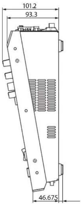
When rack-mount angles are attached
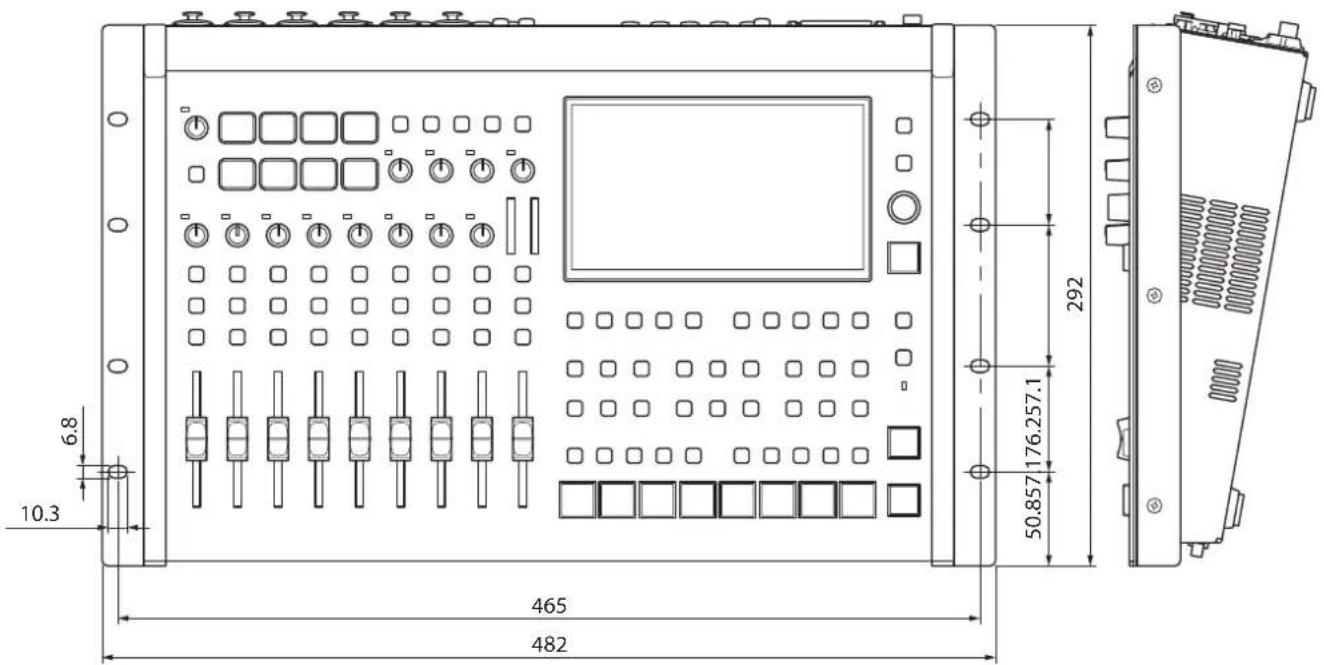
Appendix
Video Block Diagram
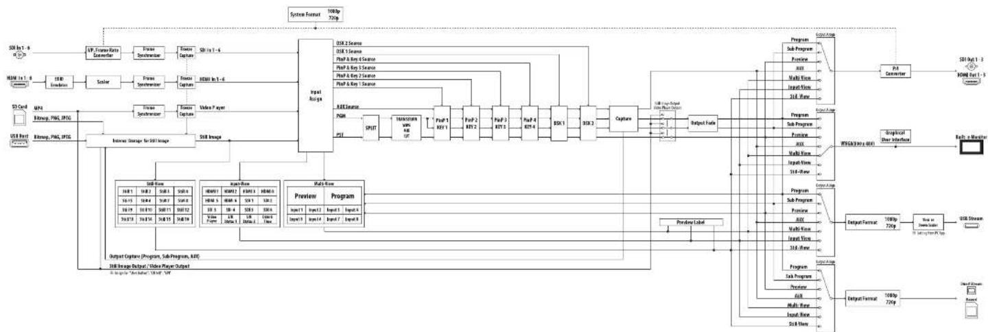
flowchart
```mermaid
graph TD
    A["Input Image"] --> B["Input Capture"]
    B --> C["Main Room"]
    C --> D["Preview Program"]
    D --> E["Output Format"]

    subgraph Inputs
        F["Input Image"] --> G["Input Capture"]
        H["Input Capture"] --> I["Input Capture"]
        J["Input Capture"] --> K["Input Capture"]
        L["Input Capture"] --> M["Input Capture"]
        N["Input Capture"] --> O["Input Capture"]
        P["Input Capture"] --> Q["Input Capture"]
        R["Input Capture"] --> S["Input Capture"]
        T["Input Capture"] --> U["Input Capture"]
        V["Input Capture"] --> W["Input Capture"]
        X["Input Capture"] --> Y["Input Capture"]
        Z["Input Capture"] --> AA["Input Capture"]
        AB["Input Capture"] --> AC["Input Capture"]
        AD["Input Capture"] --> AE["Input Capture"]
        AF["Input Capture"] --> AG["Input Capture"]
        AH["Input Capture"] --> AI["Input Capture"]
        AJ["Input Capture"] --> AK["Input Capture"]
        AL["Input Capture"] --> AM["Input Capture"]
        AN["Input Capture"] --> AO["Input Capture"]
        AP["Input Capture"] --> AQ["Input Capture"]
        AR["Input Capture"] --> AS["Input Capture"]
        AT["Input Capture"] --> AU["Input Capture"]
        AV["Input Capture"] --> AW["Input Capture"]
        AX["Input Capture"] --> AY["Input Capture"]
        AZ["Input Capture"] --> BA["Input Capture"]
        BB["Input Capture"] --> BC["Input Capture"]
        BD["Input Capture"] --> BE["Input Capture"]
        BF["Input Capture"] --> BG["Input Capture"]
        BH["Input Capture"] --> BI["Input Capture"]
        BJ["Input Capture"] --> BK["Input Capture"]
        BL["Input Capture"] --> BM["Input Capture"]
        BN["Input Capture"] --> BO["Input Capture"]
        BP["Input Capture"] --> BP1["Multi-Box"]
        BP1 --> BP2["Multi-Box"]
        BP2 --> BP3["Multi-Box"]
        BP3 --> BP4["Multi-Box"]
        BP4 --> BP5["Multi-Box"]
        BP5 --> BP6["Multi-Box"]
        BP6 --> BP7["Multi-Box"]
        BP7 --> BP8["Multi-Box"]
        BP8 --> BP9["Multi-Box"]
        BP9 --> BP10["Multi-Box"]
        BP10 --> BP11["Multi-Box"]
        BP11 --> BP12["Multi-Box"]
        BP12 --> BP13["Multi-Box"]
        BP13 --> BP14["Multi-Box"]
        BP14 --> BP15["Multi-Box"]
        BP15 --> BP16["Multi-Box"]
        BP16 --> BP17["Multi-Box"]
        BP17 --> BP18["Multi-Box"]
        BP18 --> BP19["Multi-Box"]
        BP19 --> BP20["Multi-Box"]
    end

    subgraph Outputs
        G1["Output Image"] --> H1["PMT Scan"]
        H1 --> H2["PMT Scan"]
        H2 --> H3["PMT Scan"]
        H3 --> H4["PMT Scan"]
        H4 --> H5["PMT Scan"]
        H5 --> H6["PMT Scan"]
    end

    subgraph Outputs
        H1 --> I1["PMT Scan"]
        I1 --> H4
        H4 --> H5
        H5 --> H6
    end

    subgraph Outputs
        H2 --> I2["PMT Scan"]
        I2 --> H5
        H5 --> H6
    end

    subgraph Outputs
        I3["PMT Scan"]
        I3 --> H7["PMT Scan"]
        I7["PMT Scan"]
    end

    subgraph Outputs
        I4["PMT Scan"]
        I4 --> H8["PMT Scan"]
        I8["PMT Scan"]
    end

    subgraph Outputs
        I5["PMT Scan"]
        I5 --> H9["PMT Scan"]
        I10["PMT Scan"]
    end

    subgraph Outputs
        I6["PMT Scan"]
        I6 --> H10["PMT Scan"]
    end

    subgraph Outputs
        I7["PMT Scan"]
        I7 --> H11["PMT Scan"]
    end

    subgraph Outputs
        I8["PMT Scan"]
        I8 --> H12["PMT Scan"]
    end

    subgraph Outputs
        I9["PMT Scan"]
        I9 --> H13["PMT Scan"]
    end

    subgraph Outputs
        I10["PMT Scan"]
        I10 --> H14["PMT Scan"]
    end

    subgraph Outputs
        I11["PMT Scan"]
        I11 --> H15["PMT Scan"]
    end

    subgraph Outputs
        I12["PMT Scan"]
        I12 --> H16["PMT Scan"]
    end

    subgraph Outputs
        I13["PMT Scan"]
        I13 --> H17["PMT Scan"]
    end

    subgraph Outputs
        I14["PMT Scan"]
        I14 --> H18["PMT Scan"]
    end

    subgraph Outputs
        I15["PMT Scan"]
        I15 --> H19["PMT Scan"]
    end

    subgraph Outputs
        I16["PMT Scan"]
        I16 --> H20["PMT Scan"]
    end

    subgraph Outputs
        I17["PMT Scan"]
        I17 --> H21["PMT Scan"]
    end

    subgraph Outputs
        I18["PMT Scan"]
        I18 --> H22["PMT Scan"]
    end

    subgraph Outputs
        I19["PMT Scan"]
        I19 --> H23["PMT Scan"]
    end

    subgraph Outputs
        I20["PMT Scan"]
        I20 --> H24["PMT Scan"]
    end

    subgraph Outputs
        I21["PMT Scan"]
        I21 --> H25["PMT Scan"]
    end

    subgraph Outputs
        I22["PMT Scan"]
        I22 --> H26["PMT Scan"]
    end

    subgraph Outputs
        I23["PMT Scan"]
        I23 --> H27["PMT Scan"]
    end

    subgraph Outputs
        I24["PMT Scan"]
        I24 --> H28["PMT Scan"]
    end

    subgraph Outputs
        I25["PMT Scan"]
        I25 --> H29["PMT Scan"]
    end

    subgraph Outputs
        I26["PMT Scan"]
        I26 --> H30["PMT Scan"]
    end

    subgraph Outputs
        I27["PMT Scan"]
        I27 --> H31["PMT Scan"]
    end

    subgraph Outputs
        I28["PMT Scan"]
        I28 --> H32["PMT Scan"]
    end

    subgraph Outputs
        I29["PMT Scan"]
        I29 --> H33["PMT Scan"]
    end

    subgraph Outputs
        I30["PMT Scan"]
        I30 --> H34["PMT Scan"]
    end

    subgraph Outputs
        I31["PMT Scan"]
        I31 --> H35["PMT Scan"]
    end

    subgraph Outputs
        I32["PMT Scan"]
        I32 --> H36["PMT Scan"]
    end

    subgraph Outputs
        I33["PMT Scan"]
        I33 --> H37["PMT Scan"]
    end

    subgraph Outputs
        I34["PMT Scan"]
        I34 --> H38["PMT Scan"]
    end

    subgraph Outputs
        I35["PMT Scan"]
        I35 --> H39["PMT Scan"]
    end

    subgraph Outputs
        I36["PMT Scan"]
        I36 --> H40["PMT Scan"]
    end

    subgraph Outputs
        I37["PMT Scan"]
        I37 --> H41["PMT Scan"]
    end

    subgraph Outputs
        I38["PMT Scan"]
        I38 --> H42["PMT Scan"]
    end

    subgraph Outputs
        I39["PMT Scan"]
        I39 --> H43["PMT Scan"]
    end

    subgraph Outputs
        I40["PMT Scan"]
        I40 --> H44["PMT Scan"]
    end

    subgraph Outputs
        I41["PMT Scan"]
        I41 --> H45["PMT Scan"]
    end

    subgraph Outputs
        I42["PMT Scan"]
        I42 --> H46["PMT Scan"]
    end

    subgraph Outputs
        I43["PMT Scan"]
        I43 --> H47["PMT Scan"]
    end

    subgraph Outputs
        I44["PMT Scan"]
        I44 --> H48["PMT Scan"]
    end

    subgraph Outputs
        I45["PMT Scan"]
        I45 --> H49["PMT Scan"]
    end

    subgraph Outputs
        I46["PMT Scan"]
        I46 --> H50["PMT Scan"]
    end

    subgraph Outputs
        I47["PMT Scan"]
        I47 --> H51["PMT Scan"]
    end

    subgraph Outputs
        I48["PMT Scan"]
        I48 --> H52["PMT Scan"]
    end

    subgraph Outputs
        I49["PMT Scan"]
        I49 --> H53["PMT Scan"]
    end

    subgraph Outputs
        I50["PMT Scan"]
        I50 --> H54["PMT Scan"]
    end

    subgraph Outputs
        I51["PMT Scan"]
        I51 --> H55["PMT Scan"]
    end

    subgraph Outputs
        I52["PMT Scan"]
        I52 --> H56["PMT Scan"]
    end

    subgraph Outputs
        I53["PMT Scan"]
        I53 --> H57["PMT Scan"]
    end

    subgraph Outputs
        I54["PMT Scan"]
        I54 --> H58["PMT Scan"]
    end

    subgraph Outputs
        I55["PMT Scan"]
        I55 --> H59["PMT Scan"]
    end

    subgraph Outputs
        I56["PMT Scan"]
        I56 --> H60["PMT Scan"]
    end

    subgraph Outputs
        I57["PMT Scan"]
        I57 --> H61["PMT Scan"]
    end

    subgraph Outputs
        I58["PMT Scan"]
        I58 --> H62["PMT Scan"]
    end

    subgraph Outputs
        I59["PMT Scan"]
        I59 --> H63["PMT Scan"]
    end

    subgraph Outputs
        I60["PMT Scan"]
        I60 --> H64["PMT Scan"]
    end

    subgraph Outputs
        I61["PMT Scan"]
        I61 --> H65["PMT Scan"]
    end

    subgraph Outputs
        I62["PMT Scan"]
        I62 --> H66["PMT Scan"]
    end

    subgraph Outputs
        I63["PMT Scan"]
        I63 --> H67["PMT Scan"]
    end

    subgraph Outputs
        I64["PMT Scan"]
        I64 --> H68["PMT Scan"]
    end

    subgraph Outputs
        I65["PMT Scan"]
        I65 --> H69["PMT Scan"]
    end

    subgraph Outputs
        I66["PMT Scan"]
        I66 --> H70["PMT Scan"]
    end

    subgraph Outputs
        I67["PMT Scan"]
        I67 --> H71["PMT Scan"]
    end

    subgraph Outputs
        I68["PMT Scan"]
        I68 --> H72["PMT Scan"]
    end

    subgraph Outputs
        I69["PMT Scan"]
        I69 --> H73["PMT Scan"]
    end

    subgraph Outputs
        I70["PMT Scan"]
        I70 --> H74["PMT Scan"]
Appendix
Audio Block Diagram

flowchart
graph TD
    A["Power Input"] --> B["Current Regulation"]
    B --> C{Control Path}
    C -->|Yes| D["Output 1"]
    C -->|No| E["Output 2"]
    D --> F["Current Control"]
    E --> G["Current Control"]
    F --> H["Output 3"]
    G --> I["Output 4"]
    H --> J["Output 5"]
    I --> K["Output 6"]
    J --> L["Output 7"]
    K --> M["Output 8"]
    L --> N["Output 9"]
    M --> O["Output 10"]
    N --> P["Output 11"]
    O --> Q["Output 12"]
    P --> R["Output 13"]
    Q --> S["Output 14"]
    R --> T["Output 15"]
    S --> U["Output 16"]
    T --> V["Output 17"]
    U --> W["Output 18"]
    V --> X["Output 19"]
    W --> Y["Output 20"]
    X --> Z["Output 21"]
    Y --> AA["Output 22"]
    Z --> AB["Output 23"]
    AA --> AC["Output 24"]
    AB --> AD["Output 25"]
    AC --> AE["Output 26"]
    AD --> AF["Output 27"]
    AE --> AG["Output 28"]
    AF --> AH["Output 29"]
    AG --> AI["Output 30"]
    AH --> AJ["Output 31"]
    AI --> AK["Output 32"]
    AJ --> AL["Output 33"]
    AK --> AM["Output 34"]
    AL --> AN["Output 35"]
    AM --> AO["Output 36"]
    AN --> AP["Output 37"]
    AO --> AQ["Output 38"]
    AP --> AR["Output 39"]
    AQ --> AS["Output 40"]
    AR --> AT["Output 41"]
    AS --> AU["Output 42"]
    AT --> AV["Output 43"]
    AU --> AW["Output 44"]
    AV --> AX["Output 45"]
    AW --> AY["Output 46"]
    AX --> AZ["Output 47"]
    AY --> BA["Output 48"]
    AZ --> BB["Output 49"]


- Panel Descriptions....4
- Video Input/Output Settings.... 14
- Video Operations 20
- Video Composition Operations 35
- Audio Operations 45
- Live Streaming 63
- Top Panel
- AUDIO PLAYER
- [LEVEL] knob
- SIG/PEAK indicator
- [SETUP] button
- AUDIO EFFECT
- [USB OUT] knob
- [STREAM/RECORD] knob
- SIG/PEAK indicators
- [GAIN] knobs
- [SETUP] buttons
- [SOLO] buttons
- [MUTE] buttons
- Level meters
- [SETUP] button, [SOLO] button, [MUTE] button
- [1]–[9/10] faders
- [MAIN] fader
- Display (Touch Panel)
- [MENU] button
- [EXIT] button
- [VALUE] knob
- [OUTPUT FADE] button
- USER
- [1]–[4] buttons
- MONITOR
- [AUDIO LEVEL] button
- PinP & KEY 1-4
- [SETUP] buttons
- [PVW] buttons
- [PGM] buttons
- DSK 1,2
- [CAPTURE IMAGE] button
- (Bluetooth®)indicator
- MODE
- [INPUT SELECT] button
- [AUX] button
- [SCENE MEMORY] button
- [MACRO] button
- TRANSITION
- [MIX] button
- [WIPE] button
- [SPLIT 1] button, [SPLIT 2] button
- VIDEO SWITCHER [1]–[8] buttons
- PANEL OPERATION
- [CUT] button, [AUTO] button
- Front Panel
- PHONES jack
- [PHONES] knob
- USB HOST port
- SDXC card slot
- Rear Panel
- DC IN jack
- [POWER] switch
- USB STREAM connector (USB Type-C®)
- DIRECT STREAM port
- NOTE
- REFERENCE THRU jack
- REFERENCE IN jack
- HDMI OUT 1-3 and SDI OUT 1-3 connectors
- HDMI IN 1–6 connectors, SDI IN 1–6 connectors
- Ground terminal
- RS-232 connector
- CTL/EXP 1, 2 jacks
- TALLY/GPIO connector
- AUDIO OUT (XLR, RCA) jacks
- AUDIO IN 1-6 (XLR/TRS) jacks
- \* About phantom power
- AUDIO IN 7/L, 8/R (LINE IN) jacks
- AUDIO IN 9/L, 10/R (LINE IN) jacks
- Connecting Bluetooth ® Devices
- Registering a Bluetooth Audio Device (Pairing)
- Connecting an Already-Paired Bluetooth Device
- MEMO
- Turning the Power On/Off
- Turning the Power On
- Turning the power off
- Operating the Menu
- Operating the Setup Screen
- Switching the Monitor View
- Press one of the MONITOR [1], [2], [3] or [4] buttons.
- MONITOR [1] (MULTI-VIEW) button
- PVW (preview) section
- PGM (program) section
- VIDEO SWITCHER [1]–[8] button video
- External Rec indicator
- AUX/Source indicator
- Setup screen
- MONITOR [2] (INPUT-VIEW) button
- MONITOR [3] (STILL-VIEW) button
- MONITOR [4] (PROGRAM) button
- Audio level meter indication
- - Items shown on the monitor
- About SD Card
- SD cards that can be used on the VR-120HD
- Inserting the SD Card
- Formatting an SD Card
- Removing an SD Card
- About USB Flash Drive
- USB Flash Drives that can be used on the VR-120HD
- Formatting a USB Flash Drive
- Removing a USB Flash Drive
- Setting the Video Input/Output Format
- Setting the System Format
- Internal processing
- About frame rate
- Setting the Input Format for the HDMI IN 1–6 Connectors
- What is EDID?
- Assigning Video Sources
- Adjusting Output Video
- HDMI Out 1-3
- Adjusting Input Video
- Assigning Video Buses to Output Connectors
- Assigning the video buses and audio outputs
- Selecting the Video Sent to the AUX Bus
- Press the [AUX] button.
- Press the VIDEO SWITCHER [1]–[8] buttons to select the video signal to send to the AUX bus.
- Configuring on the setup screen
- With the [AUX] button lit up, press the MODE [SETUP] button.
- Touch the screen to select the video signal to send to the AUX bus.
- Inputting Copy-Protected (HDCP) Video
- What's HDCP?
- [MENU] button → "System" → select "HDCP", and press the [VALUE] knob.
- Press the [MENU] button to close the menu.
- Checking for HDCP-capable devices
- Source devices
- Output devices
- Specifying a Reference Clock
- When set to "External" or "SDI 1-6"
- Switching the Video
- Setting the Operation Mode
- Dissolve mode (factory setting)
- PGM/PST mode
- Switching in the Dissolve Mode
- Switching in the PGM/PST Mode
- Changing the Mix Pattern
- Changing the Wipe Pattern
- Splitting the Video
- Positioning a video
- Configuring the Screen Layout
- Displaying the Split
- Switching the Video Automatically (Auto Switching)
- About the Operation Mode
- Switching at a specified interval (input scan)
- Switching scene memories (scene memory scan)
- Switching in sync with the beat of the music (beat sync)
- Switching according to the mic volume (video follows audio)
- Switching between picture-in-picture (PinP) content (PinP & Key scan)
- Switching between downstream keyer (DSK) content (DSK scan)
- Turning the Auto Switching Function On/Off
- Input scan
- Scene memory scan
- Beat sync
- Video follows audio
- PinP&KEY scan
- DSK scan
- Loading a Still Image
- Loading a Still Image from a Storage
- Formats supported for loading
- Capturing a Still Image from Input/Output Video
- Outputting a Loaded Still Image
- Assigning a Still Image to the VIDEO SWITCHER Buttons
- Inserting a Still Image in the Final Output
- Using the USER buttons
- Using a footswitch
- Using an expression pedal
- Inputting an external control signal (GPI)
- Outputting a still image with a fade-in effect
- Deleting a Still Image
- Saving a Still Image to a SD Card or USB Flash Drive
- Insert the SD card into the SDXC card slot.
- [MENU] button → "Still Image" → "Save To Storage" → select "Still Image", and press the [VALUE] knob.
- 3.
- Use the [VALUE] knob to select the still image (Still 1–16) you want to save, and press the [VALUE] knob.
- Press the [EXIT] button to return to the previous screen.
- Use the [VALUE] knob to select "Save", and press the [VALUE] knob.
- Select "File Name" and press the [VALUE] knob.
- Enter a file name.
- Touch in software keyboard.
- Select the file type
- Use the [VALUE] knob to select "Save", and press the [VALUE] knob.
- Use the [VALUE] knob to select "OK", and press the [VALUE] knob.
- Press the [MENU] button to close the menu.
- Overwriting a still image
- Importing a Video
- Outputting a Loaded Video
- Playing Back a Video (with the Video Player)
- Assigning a USER button
- Video player settings
- Assigning Videos to the VIDEO SWITCHER Buttons
- Inserting a Video in the Final Output
- Freezing the Input Video (Freeze)
- Press the USER [SETUP] button.
- Touch User 1 .
- Touch to select the operating mode.
- Value Explanation
- If "Select" is selected
- Touch the screen to specify a source from "HDMI 1" to "SDI 6".
- Press the [SETUP] button to close the screen.
- Freezing the Input Video
- Press the USER [1] (FREEZE) button to turn freeze on (the button lights up).
- To turn freeze off, press the USER [1] (FREEZE) button again.
- Fading-In/Out the Final Output Video
- Press the [OUTPUT FADE] button.
- To fade-in, press the [OUTPUT FADE] button once again.
- Compositing Video with Picture-in-Picture (PinP)
- Making adjustments by touching the inset screen
- Turning PinP/DSK composition on/off in tandem with video transitions
- Making Detailed Settings for the Inset Screen
- Swapping and copying settings
- Key Compositing the Inset Screen
- Luminance key
- Chroma key
- Compositing Video with Downstream Keyer (DSK)
- About DSK Mode
- Self key Luminance key (p. 39)
- Chroma key (p. 40)
- Alpha key (p. 42)
- External key (p. 43)
- Compositing a Caption or Image (Luminance Key)
- Compositing using DSK
- Press the DSK 1 [SETUP] button to turn on (lit).
- Touch the setup screen to make the following settings.
- Press a VIDEO SWITCHER [1]–[8] button to select the DSK video source.
- Press the DSK 1 [PVW] button to turn on the preview output (lit).
- Touch the setup screen to adjust the intensity of the effect.
- Press the DSK 1 [PGM] button to turn on DSK compositing (lit).
- To turn off DSK compositing, press the DSK 1 [PGM] button once again.
- Turning DSK/PinP composition on/off in tandem with video transitions
- Modifying the caption or image
- Compositing a Subject and Background (Chroma Key)
- Finely adjusting the key color
- Modifying the superimposed video
- Specifying a desired color as the key color (sampling marker)
- Compositing a Still Image with Alpha Channel
- Using an External Key
- Press a VIDEO SWITCHER [1]–[8] button to select the fill source.
- Assigning Audio Sources to Audio Channels
- Adjusting the Input Gain (Sensitivity)
- Stereo link function
- Adjusting the mic position (pan)
- Adjusting the digital gain
- Adjusting the Volume Balance
- Move the [MAIN] fader to a position near the "0 dB".
- While monitoring the audio via speakers or headphones, adjust the volume balance for the respective inputs.
- Use the [MAIN] fader to adjust the volume of the output.
- Adjusting the Volume Balance from the Mixer Screen
- Press the [AUDIO LEVEL] button.
- Drag the faders on the screen to adjust the volumes.
- Press the [AUDIO LEVEL] button to close the screen.
- Applying Effects to Input Audio
- Using an Effect Preset
- Touch the page tab at the top right-hand corner of the channel setup screen to select page 2.
- Select an effect preset by touching the screen.
- Use the [VALUE] knob to select "OK", and press the [VALUE] knob.
- Configure the settings for each effect as necessary.
- Suppressing Echo in a Web Conference System (Echo Canceller)
- Reducing Acoustic Feedback (Anti-Feedback)
- Parameter Explanation
- Changing the Character of a Voice (Voice Changer)
- Correcting a Time Difference Between Video and Audio (Delay)
- Applying Reverb
- Adjusting how much reverb is returned
- Applying Effects to Output Audio
- Press the MAIN [SETUP] button.
- Touch for each bus.
- Touch the screen to access the settings.
- Press the lit [SETUP] button to close the setup screen.
- Equalizer
- Delay
- Compressor/Limiter
- Graphic Equalizer
- ●Adaptive Noise Reduction (p. 53)
- ● Loudness Auto Gain Control (p. 54)
- Interlinking Audio Output to Video Switching (Audio Follow)
- Adding an Object for Audio Follow
- Removing Noise from the Audio (Adaptive Noise Reduction / Low Frequency Cut)
- ● Adaptive Noise Reduction
- Low Frequency Cut
- Adaptive Noise Reduction
- Automatically Setting a Comfortable Volume (Auto Mastering Effect)
- ● Loudness Auto Gain Control (Loudness AGC)
- Loudness Auto Gain Control (Loudness AGC)
- Press the AUDIO EFFECT [SETUP] button to turn on (lit).
- Touch Audio Effect 2 .
- Touch to set the target level for the output audio.
- Press the AUDIO EFFECT [LOUDNESS AGC] button to turn on (lit).
- Touch and then use the [VALUE] knob to adjust the sensitivity, adjusting the speed at which the target level (Target LKFS) is approached.
- To reset the adjusted value and return to the original state, touch .
- Controlling the Volume Automatically (Auto Mixing)
- Silencing Only Specific Audio (Mute)
- Muting Input Audio
- Setting on the audio level screen
- Muting the Output Audio
- Checking a Specific Audio Input (Solo)
- Soloing the Input Audio
- Soloing the Output Audio
- Playing Back Audio Files (Audio Player)
- Importing an Audio File
- Playing Back Audio Clips
- Setting an Audio Clip
- Swapping, copying and deleting clips
- Inputting the name of an audio clip
- w r r ! y w i o p
- Mixer Settings for the Audio Player
- Press the AUDIO PLAYER [SETUP] button.
- Touch Mixer Input .
- Touch the screen to configure the send amount for each bus.
- Outputting AUX-bus Audio
- Assigning the AUX Bus
- Sending Audio to the AUX Bus
- Setting the character of the sound
- Adding Input Audio to an HDMI or SDI Video for Output
- Assigning HDMI/SDI embedded audio and sound
- As a backup for visual or sound recording...
- For multilingual support...
- Assigning the audio
- Outputting Video/Audio to a Computer for Streaming
- Outputting Video and Audio to the Computer
- Video formats
- Using the Loopback Function
- Streaming Video from a Computer
- https://proav.roland.com/
- Capturing Video on the Computer
- What to do when an HD video (1920 x 1080) output via USB changes to SD video (640 x 480)
- Streaming/Capturing Video Directly
- Internet connection, including DNS server settings
- Continuous TCP communications
- HTTPS connection to an Internet server
- Points to Be Aware of When Livestreaming
- Starting/Stopping the Livestream, Audio or Video Recording
- Turning Livestreaming, Audio and Video Recording ON/OFF
- Turning the livestream on/off
- Turning video and audio recording on/off
- Livestreaming via YouTube Live
- Getting ready
- Operating this unit
- Operating your computer or smartphone
- Livestreaming via Facebook Live
- Livestreaming via Twitch
- Streaming with Custom Settings
- Tethering
- iPhone:
- Android devices:
- Avoiding Sporadic Issues When Livestreaming (Safety Delay)
- Setting the Streaming Delay Time
- Using the safety delay function
- Assigning safety delay to a USER button
- Saving/Recalling Settings (Scene Memory)
- About the Last Memory function
- Saving to a Scene Memory
- Only for scene memories 1–8
- Scene memory 1–32
- Recalling a Scene Memory
- Initializing a Scene Memory
- Renaming a Scene Memory
- Changing the Thumbnail Position
- With the [SCENE MEMORY] button lit up, press the MODE [SETUP] button.
- Touch .
- Touch the area of the scene memory number that you want to change.
- Touch the screen to access the settings.
- Press the [EXIT] button.
- Saving Scene Memories to an SD Card or USB Flash Drive
- Saving a new file
- [MENU] button → "Scene Memory" → select "Save To Storage", and press the [VALUE] knob.
- Select "File Name" and press the [VALUE] knob.
- Input the scene memory file name.
- Touch in software keyboard.
- Overwrite-saving
- Loading
- Recording Multiple Operations to Automatically Execute (Macros)
- Recording a Macro
- Press the [MACRO] button.
- Press the MODE [SETUP] button.
- Touch .
- Touch the screen to select a macro to edit.
- Touch .
- Touch to select the operation to record to the macro.
- Touch the screen to configure the related parameters.
- Touch to set the timing used to execute the operation.
- Press the [EXIT] button to return to the previous screen.
- Repeat steps 5–9 to finish making the macro.
- Press the [EXIT] button to close the screen.
- Editing a macro
- Editing the contents of a function
- Copying a function
- Moving a function
- Deleting a function
- Directly recording the panel operations to a macro
- Executing a Macro
- Only for macros 1–8
- Macro 1-100
- Assigning macros to the VIDEO SWITCHER buttons
- Copying Macro Settings
- Swapping the Macro Settings
- Initializing a Macro
- Renaming a Macro
- Saving/Loading the Macro Settings
- [MENU] button → "Macro" → select "Save To Storage", and press the [VALUE] knob.
- Input the macro setting file name.
- Use the [VALUE] knob to select "Save", and then press the [VALUE] knob.
- Use the [VALUE] knob to select "OK", and then press the [VALUE] knob.
- Press the [MENU] button to close the menu.
- Touch the macro settings file that you want to overwrite.
- Use the [VALUE] knob to select "Save", and then press the [VALUE] knob.
- Use the [VALUE] knob to select "OK", and then press the [VALUE] knob.
- Press the [MENU] button to close the menu.
- [MENU] button → "Macro" → select "Load From Storage", and press the [VALUE] knob.
- Touch the macro settings file that you want to recall.
- Use the [VALUE] knob to select "OK", and then press the [VALUE] knob.
- Press the [MENU] button to close the menu.
- Initializing All Macros
- [MENU] button → "Macro" → select "Initialize", and press the [VALUE] knob.
- Use the [VALUE] knob to select "OK", and then press the [VALUE] knob.
- Press the [MENU] button to close the menu.
- Combining Scene Memories and Macros for Operations (Sequencer)
- Recording to the Sequencer
- Touch User 4 .
- Touch the "Function" column of the line you want to add, and select the operation to record to the sequencer.
- Configure the related parameters.
- Repeat steps 3–5 to finish making the list.
- Press the [EXIT] button to close the menu.
- Editing a list
- Running the Sequencer
- Press the USER [4] (SEQUENCER) button to turn the sequencer function on (the button lights up).
- Press the [AUTO] (NEXT) button.
- Press the [AUTO] (NEXT) button at the timing when you want the next function to execute.
- Repeat step 3.
- Press the USER [4] (SEQUENCER) button again to turn the sequencer function off.
- Repeatedly executing a function in the list
- Executing a function from the middle of the list
- Making the Sequencer Run Automatically (Auto Sequence)
- Configuring the auto sequence settings
- Running the auto sequence
- When a function is set to "PAUSE"
- Saving/Loading the Sequencer Settings
- Initializing the Sequencer
- About the sequencer demo data
- Backing Up and Restoring the Unit's Settings
- Backing Up
- [MENU] button → "SD Card/USB Memory" → select "Backup All Settings", and press the [VALUE] knob.
- Touch the backup file that you want to overwrite.
- Restoring
- [MENU] button → "SD Card/USB Memory" → select "Restore All Settings", and press the [VALUE] knob.
- Touch the settings file that you want to restore.
- Use the [VALUE] knob to select "OK", and then press the [VALUE] knob.
- Assigning Functions to the USER Buttons
- Value
- Controlling an External Recorder's Video Record Start/Stop from the VR-120HD
- Setting
- Turning REC control on/off
- Operation
- Remotely Controlling a PTZ Camera
- Network Settings on the Camera
- Network settings for the camera
- Registering Camera Settings in a Preset
- Recalling a Preset
- Recalling presets with the buttons
- Adjusting the Pedal (Pedal Calibration)
- Assigning a Function to the Pedal
- Control Using the TALLY/GPIO Connector
- Specification of the TALLY/GPIO Connector
- Inputting a Control Signal
- Outputting a Tally Signal
- Outputting a Control Signal
- Assigning the GPOs
- Using Smart Tally
- Connecting via a Wireless LAN Router
- Starting Smart Tally
- Preventing Unintended Operation (Panel Lock)
- [MENU] button → "System" → select "Panel Lock", and press the [VALUE] knob.
- Use the [VALUE] knob to select a target for panel lock, and press the [VALUE] knob.
- Use the [VALUE] knob to specify whether panel lock is enable (ON) or disable (OFF), and press the [VALUE] knob.
- Press the [MENU] button to close the menu.
- Returning to the Factory Settings (Factory Reset)
- [MENU] button → "System" → select "Factory Reset", and press the [VALUE] knob.
- Remotely Controlling the VR-120HD
- Using the dedicated apps "VR-120HD RCS" and "VR-120HD Remote"
- VR-120HD RCS (Windows/Mac)
- Wireless connection
- Wired connection (via cable)
- VR-120HD Remote
- LAN/RS-232 command
- MIDI implementation
- About Rack Mounting
- Attaching the Rack-Mount Angles
- When uninstalling the rack-mount angles
- Important Notes on Rack Mounting
- Dimensions
- Video Block Diagram
Brand : ROLAND
Model : VR-120HD
Category : Table de mixage audio-vidéo