RE22T - Regulator PCE Instruments - Free user manual and instructions
Find the device manual for free RE22T PCE Instruments in PDF.


| Product Type | Temperature / Process Controller (Régulateur) |
| Model | PCE Instruments RE22T |
| Dimensions (W x H x D) | 48 x 48 x 70 mm (front panel), depth behind panel: 93 mm max |
| Panel Cutout | 45 x 45 mm (with tolerance +0.6 mm) |
| Weight | < 0.25 kg |
| Supply Voltage | 230 V AC ±10% (also 110 V AC or 24 V AC options) |
| Power Consumption | < 3 VA |
| Input Type | Universal: RTD (Pt100, Pt1000), Thermocouples (J, K, T, S, R, B, E, N, L), Linear current (0/4-20 mA), Linear voltage (0-5/10 V) |
| Output | Relay (SPDT, 5 A / 250 V AC) or Binary voltage 0/5 V (for SSR), configurable as heating or cooling |
| Control Modes | ON/OFF with hysteresis, P, PI, PD, PID, Auto-tune |
| Display | LED, 4 digits, red, shows measured value, set point, and parameters |
| Front Panel Protection | IP40 (front), IP20 (rear) |
| Operating Temperature | 0 to 50 °C |
| Storage Temperature | -20 to +70 °C |
| Relative Humidity | < 85% non-condensing |
| Basic Accuracy | 0.2% for RTD, 0.3% for TC (0.5% for B/R/S), 0.2% ±1 digit for linear inputs |
| Measurement Time | 0.33 s for sensor inputs, 0.16 s for linear inputs |
| Safety Standards | EN 61010-1, Installation Category III, Pollution Degree 2 |
| EMC Compliance | Immunity: EN 61000-6-2, Emission: EN 61000-6-4 |
| Additional Functions | Manual control, Soft-start (set point ramp), Password protection, Sensor error output configuration |
| Mounting | Panel mount, 2 screw holders, panel thickness max 15 mm |
| Accessories Included | Controller, 6-pin and 8-pin screw terminal plugs, 2 panel holders, user manual |
Frequently Asked Questions - RE22T PCE Instruments
User questions about RE22T PCE Instruments
0 question about this device. Answer the ones you know or ask your own.
Ask a new question about this device
Download the instructions for your Regulator in PDF format for free! Find your manual RE22T - PCE Instruments and take your electronic device back in hand. On this page are published all the documents necessary for the use of your device. RE22T by PCE Instruments.
USER MANUAL RE22T PCE Instruments
Southpoint Business Park
Ensign way
Hampshire / Southampton
United Kingdom, SO31 4RF
From outside UK: +44
Tel: (0) 2380 98703
Fax: (0) 2380 98703 9
info@pce-instruments.co.uk
www.pce-instruments.com/english
www.pce-instruments.com
CONTROLLER WITH UNIVERSAL INPUT AND 1 OUTPUT PCE- SERIES RE22

natural_image
Two industrial control modules: one with green terminal connectors and one displaying a digital display showing red LED, no visible text or symbols.USER'S MANUAL
CE
CONTENTS
1' APPLICATION 5
2' CONTROLLER SET 6
3' CONTROLLER PREPARATION TO WORK 6
3'1 Safety 6
3'2' Controller installation in the panel 7
3'3' Electrical connection 8
3.4 Installation recommendations 9
4' STARTING TO WORK 10
5' PROGRAMMING OF CONTROLLER PARAMETERS 11
5'1' Scheme of the controller menu 11
5'2 Setting change 13
5'3' List of parameters 14
6' INPUTS AND OUTPUTS OF THE CONTROLLER 17
6'1' Measuring input 17
6'2 Output 18
7' CONTROL 19
7'1' ON 'OFF control 19
7'2 PID control 19
8' ADDITIONAL FUNCTIONS 20
8'1' Display of the control signal 20
8'2 Manual control 20
8'3' Controller reaction after sensor damage 20
8'4' Rate of the set point change 21
8'5' Manufacturer's settings 21
9' SELECTION OF PID PARAMETER SETTINGS 21
9'1 Auto-tune function 21
9'2' Manual selection of PID parameter settings 23
10' SIGNALLING OF ERRORS 25
11' TECHNICAL DATA 26
12' ORDER CODES 29
1' APPLICATION
PCE-
The ^1 RE22 controller co-operates directly with resistance thermometers (RTD) and thermocouples (TC) or quantity converters into a standard signal.
It is destined for temperature control in plastics' food' glass' ceramics' dehydration industries and everywhere when it is necessary to stabilize temperature changes.
The measuring input is universal for resistance thermometers and thermocouple sensors or for linear standard signals.
The relay output with a make-brake configuration (with NOC or NCC contacts) allows to the direct control of low power objects.
The manual control and soft-start are also possible.
One can protect the controller against the undesirable change of parameters by means of a password:
The auto-tuning function permits to select the PID setting in order to a quick output signal adaptation to object parameters:
2' CONTROLLER SET


natural_image
Isometric line drawing of a connector with multiple slots and circular pins (no text or symbols)
natural_image
Isometric line drawing of a 3D rectangular block with internal grid pattern and a circled number 3 (no text or symbols on the block itself)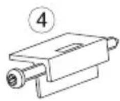
natural_image
Simple line drawing of a mechanical component with a numbered label (4) and no text or symbols on the body.The controller set is composed of.
1 controller 1 pc
2' plug with 6 screw terminals 1 pc
3' plug with 8 screw terminals 1 pc
4' holder to fix in the panel 2 pcs
5' user's manual 1 pc
When unpacking the controller' please check whether the type and option code on the data plate correspond to the order
3' CONTROLLER PREPARATION TO WORK
3'1' Safety
The PCE-RE22 controller fulfils requirements concerning the safety of automation measuring instruments acc to the EN 61010-1 standard' requirements concerning the fastness against electromagnetic interference acc to EN 61000-6-2 standard and emission of electromagnetic interference occurring in the industrial environment' acc to the EN 61000-6-4 standard
3'2' Controller installation in the panel
Fix the controller in the panel by means of two screw holders acc to the fig'1. The hole in the panel should have 45^+0.6 × 45^+0.6 mm dimensions. The material thickness what the panel is made of cannot exceed 15 mm.

Fig 1. Controller fixing
Controller overall dimensions are presented on the fig' 2'

Fig 2 View of controller connection strips
3'3' Electrical connections
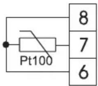
Carry out electrical connections to terminal strips and next insert strips into controller sockets'

Fig 3 View of controller connection strips

Pt100 resistance thermometer in 2-wire system
Pt100 resistance thermometer in 3-wire system

Pt1000 resistance thermometer

flowchart
graph TD
    A["•"] --> B["-"]
    A --> C["+"]
    B --> D["5"]
    B --> E["4"]
Thermocouple

Current input 0/4\~20mA
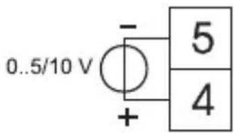
Voltage input
0.5/10V
Fig 4 Connection of input signals

flowchart
graph TD
    A["13"] --> B["~"]
    C["14"] --> B
    B --> D["9"]
    D --> E["Load"]
    D --> F["10"]
    F --> G["Supply"]
    F --> H["11"]
Supply Output - relay

flowchart
graph LR
    A["10"] --> B["SSR"]
    C["11"] --> B
    B --> D["Load"]
    D --> E["Supply"]
    style A fill:#f9f,stroke:#333
    style C fill:#f9f,stroke:#333
    style B fill:#ccf,stroke:#333
    style D fill:#cfc,stroke:#333
    style E fill:#fcc,stroke:#333
Output - binary voltage to control SSR
Fig 5: Connection of the supply and load circuit
When connecting the supply' one must remember that an automatic cut-off should be installed near the device' easily accessible for the operator and suitably marked.
3'4' Installation recommendations
The "PULREZZ" controller fulfils requirements concerning the fastness against electromagnetic interference occurring in the industrial environment acc' to obligatory standards.
In order to obtain a full immunity of the controller against electromagnetic interference in an unknown environment interference level it is recommended to observe following principles:
- do not supply the controller from the network near devices generating high impulse interference and do not use common earthing circuits with them'
- apply network filters'
- apply metallic shields in the shape of tubes or braided screens to conduct supplying wires'
- wires supplying the measuring signal should be twisted in pairs' and for resistance thermometers in a 3-wire connection' twisted from wires with the same length' cross-section and resistance, and led in a shield as above'
- all screens should be one side earthed' and led the nearest possible to the controller'
- apply the general principle that wires leading different signals should be led the farthest possible between them (not less than 30 cm)' and their crossing executed at a right angle.
4' STARTING TO WORK

Fig 6 View of the controller frontal plate
After connecting to the power, the controller carries out the display test and displays the 'ε22 inscription' the program version, and next displays the measured value.
A character message can appear on the display' informing about abnormalities' (table 4).
The algorithm of ON-OFF control with a 2^ C hysteresis is set by the manufacturer.
Change of the set point
The way to change the set point during the normal work is shown on the fig. 7. The change limitation is set by SPL and SPH parameters.

Fig 7 Change of the set point during the normal work
5' PROGRAMMING OF CONTROL PARAMETERS
5'1' Scheme of the controller menu
After pressing and holding the push-button during at least 2 sec' it is possible to program parameters: The transition between parameters is carried out by means of and push-buttons.
The return to the normal working mode follows after the simultaneous pressure of and push buttons' or automatically' after
30 sec from the last push-button pressure
Some parameters can be invisible - it depends on the current controller configuration:

flowchart
graph TD
    A["Monitoring of control signal"] --> B["Manual work"]
    B --> C["Auto-tuning start"]
    C --> D["Measured value"]
    D --> E{active access code}
    E -->|T| F["CodeE"]
    E -->|N| G{correct code?}
    G -->|3sec| H["Err"]
    I["Next parameter"] --> J["Previous parameter"]
    J --> K["1-pb t-l r-l CuC CuCt dp nlo nhi Sh,F SPrr rRnP SPL SPH Pb t- to hy out FA,L 8tFn SEcu"]
    K --> L["Start of changes or acceptance of change"]
    L --> M["Decrease of value or previous accounted parameter"]
    M --> N["1-dp OUT SP MAN AT"]
    N --> O["Decrease of value or next accounted parameter"]
    style A fill:#f9f,stroke:#333
    style B fill:#ccf,stroke:#333
    style C fill:#cfc,stroke:#333
    style D fill:#fcc,stroke:#333
    style E fill:#cff,stroke:#333
    style F fill:#ffc,stroke:#333
    style G fill:#cfc,stroke:#333
    style H fill:#fcc,stroke:#333
    style I fill:#fff,stroke:#333
    style J fill:#fff,stroke:#333
    style K fill:#fff,stroke:#333
    style L fill:#fff,stroke:#333
    style M fill:#fff,stroke:#333
    style N fill:#fff,stroke:#333
    style O fill:#fff,stroke:#333
The access to parameters can be protected by a code. If the safety code is set (parameter SECU is higher than zero), one must give it. If the value will not be given or will be erroneous, the inscription ERR appears on displays' and the user will be only able to monitor parameter values:
5'2' Setting change
The change of parameter setting begins after pressing the push-button. By means of and push-buttons we make the choice of the setting and by the push-button we accept it. The cancellation of the change follows after the simultaneous pressure of and push-buttons or automatically after 30 sec from the last push-button pressure. The way of setting change is presented on the fig'9.

flowchart
graph TD
    A["Start of change"] --> B["1234"]
    B --> C{decrease the value}
    B --> D{increase the value}
    C --> E["cancellation of change"]
    D --> F["acceptation of change"]
    G["Start of change"] --> H["onOF"]
    H --> I{previous parameter}
    H --> J["next parameter}<br>    I --> K[cancellation of change"]
    J --> L["acceptation of change"]
Fig 9 Setting change of numerical and textual parameters
5'3' List of parameters
The list of controller parameters is presented in the table 1.
Table 1
| parameter symbol | parameter description | range of parameter changes | |
| sensor linear signal | |||
| ' nPt | kind of input (description in table 2) | [Pt1]: Pt100Pt10: Pt1000 ^- : thermocouple of J type ^- : thermocouple of T type ^- : thermocouple of K type ^- : thermocouple of S type ^- : thermocouple of R type ^- : thermocouple of B type ^- : thermocouple of E type ^- : thermocouple of N type ^- : thermocouple of L type | 0-20:lin current 0-20 mA[4-20]:lin current 4-20 mA0-5:lin voltage 0-5 V0-10:lin voltage 0-10 V |
| ^- :L' | line type (2-wire or 3-wire line) ^1) | [2-P]: 2-wire line3-P: 3-wire line | —— |
| ^- :L' | resistance of 2-wire line' for Pt100 sensor | 0·0···20·0 Ω[0·0] | —— |
| CUC | way of cold ends compensation for thermocouples ^2) | [RUTO]: automatic compensationHand: manual compensation | —— |
| CUCt | temperature of cold ends during the manual compensation[°C×10] ^2) | 0·0···50·0°C[0·0] | —— |
| dP'ɔːo | position of the decimal pointindication for the lower threshold of analog input | 0-dP: without decimal place1-dP: 1 decimal place—— | 0-dP: without decimal place1-dP: 1 decimal place2-dP: 2 decimal place ^-1999 *** 9999^3) [0.0] |
| 'ɔːh' | indication for the upper threshold of analog input | —— | ^-1999 *** 9999^3) [100.0] |
| SHF | shift of the measurement value | -99.9***99.9°C[0.0] | ^-999 *** 999^3) [0.0] |
| SPrr | accretion rate of the set point | 0***999.9 / unit[0.0] | 0***999.9 / jedn·[0.0] |
| rRnP | time unit for the accretion rate of the set point | [n' n]: minutehour: hour | [n' n]: minutehour: hour |
| SPL | lower setting limitation of the set point | acc to table 2^3) [-199.0] | INLO***INHI ^3) [0.0] |
| SPH | upper setting limitation of the set point | acc to table 2^3) [850.0] | INLO***INHI ^3) [100.0] |
| Pb | proportional band | 0***999.9 °C[0.0] | 0***9999 ^3) [0.0] |
| paramet^er symbol | paramet^er description | range of parameter changes | |
| sensor | linear signal | ||
| t' | integration time-constant^4) | 0···9999 s[0] | 0···9999 s[0] |
| t o | differentiation time-constant^4) | 0···999.9 s[0.0] | 0···999.9 s[0.0] |
| t o | pulse repetition period of the output^4) | 0.5···99.9 s[20.0] | 0.5···99.9 s[20.0] |
| HY | histeresis^5) | 0.2···99.9[2.0] | 0.2···999 ^3) [2.0] |
| out | output configuration | d' r : cooling signal['ou]: heating signal | |
| F\&'L | control signal of the output for proportional control in case of sensor damage^4) | 0···100.0%[0.0] | 0···100.0%[0.0] |
| Rt.F | auto-tuning function | off: locked[on]: unlocked | |
| SECU | safety code^6) | 0···9999[0] | 0···9999[0] |
1) The parameter is visible only for Pt100 resistance thermometer
2) The parameter is visible only for the execution with thermocouple inputs:
^3) Resolution what the given parameter is shown with' depends on the dP parameter - position of the decimal point:
4) The parameter is invisible at ON-OFF control
5) The parameter is visible at ON-OFF control
^6) The parameter is hidden in the parameter review mode only for readout (for readout only)
Measuring ranges for inputs
Table 2
| Symbol | Input / sensor Minimum Maximum | ||
| Pt1 | Resistance thermometer Pt100~199°C 850°C | ||
| Pt10 | Resistance thermometer Pt1000~199°C 850°C | ||
| t-1 | Thermocouple J type | ~100°C | 1200°C |
| t-2 | Thermocouple T type | ~100°C | 400°C |
| t-3 | Thermocouple K type | ~100°C | 1372°C |
| t-5 | Thermocouple S type | 0°C | 1767°C |
| t-7 | Thermocouple R type | 0°C | 1767°C |
| t-8 | Thermocouple B type | 0°C | 1820°C |
| t-9 | Thermocouple E type | ~100°C | 999°C |
| t-10 | Thermocouple N type | ~100°C | 1300°C |
| t-11 | Thermocouple L type | ~100°C | 800°C |
| 0~20 | Linear current 0~20 mA | ~1999 | 9999 |
| 4~20 | Linear current 4~20 mA | ~1999 | 9999 |
| 0~5 | Linear voltage 0~5 V | ~1999 | 9999 |
| 0~10 | Linear voltage 0~10 V | ~1999 | 9999 |
6' INPUTS AND OUTPUTS OF THE CONTROLLER
6'1' Measuring input
The controller has one measuring input' which on can connect different types of sensors or standard signals to
The choice of the input signal is performed by the 'opt' parameter. For different types of inputs' depending on the option code, one must give additional parameters:
For the Pt100 resistance thermometer' one must choose the kind of connection. In a three-wire connection' the line resistance compensation goes on automatically
In a two-wire connection' one can give additionally the line resistance' for thermocouples' one must give the way of temperature compensation of cold ends - automatic or manual' and at manual compensation - the temperature of cold ends.
For linear inputs' one must give indications for the lower and upper threshold of the analog input. The position of the decimal point is an additional parameter, the parameter dP .
For temperature sensors' it defines whether the measured temperature and the set point temperature is to be shown with a place after the decimal point
For linear inputs' it defines the resolution which the measured value and values of some parameters are shown with
The correction of measured value indications is carried out by the 5x' F parameter
6'2' Output
The controller has one measuring input with a switch over contact. It is possible to select the ON-OFF control or proportional (PID) control at the output. For the proportional control, one must additionally set the pulse repetition period. The pulse repetition period is the time which expires between successive switches of the output during the proportional control. The length of the pulse repetition period must be chosen depending on dynamic properties of the object and suitably to the output device for quick-acting processes, it is recommended to apply SSR relays. The relay output is used to control contactors in slow-acting processes.
The use of a high pulse repetition period to control quick-acting processes can give unwanted effects in the shape of oscillations. Theoretically' smaller the pulse repetition period better the control is but for the relay output it should be as high as possible in order to extend the relay life:
Recommendations concerning the pulse repetition period Table 3
| Output Pulse repetition period is Load | ||
| electromagnetic recommended >20 s 2 A/230 V a·c·relay min·10 s or contactor | ||
| min·5 s 1 A/230 V a·c· | ||
| transistor output 1··· | 3 s Semi-conductor | relay (SSR) |
7° CONTROL
7'1' ON-OFF control
To select the ON-OFF control' one must set the parameter p_b = 0 . Next' set the hysteresis value - y . The action of the output on heating (fig. 10') is set by the parameter out = 'n' and on cooling by the parameter out = d' .

line
| output | measured value | | ------ | -------------- | | enabled | 0 | | disabled | SP |Fig 10' Operation way of the heating type output
7'2' PID control
The choice of PID control' or also PI' PD or P control' consists on a suitable setting of parameter values - proportional band (Pb)' integrating element (t') and differentiating element(t d). The switching of the giving element off consists on setting the parameter on zero. The operation way of the heating type output is chosen by setting the parameter out! = 'ou' and the cooling type by setting the parameter out=d'. The successive parameter to set is the pulse repetition period of the output (t0).
8' ADDITIONAL FUNCTIONS
8'1' Display of the control signal
After pressing the push-button' the value of the control signal (0…100%) appears on the display. On the first digit' the mark h is displayed. The return to the normal operation follows after the simultaneous pressure of and push-buttons.
8'2' Manual control
The manual control gives the possibility' among other things' to identify and test the object or control it after the sensor damage.
The entry into the manual control mode follows after holding down the push-button when displaying the control signal. The manual
control is signaled by the diode pulsation' marked as MAN. The controller breaks the automatic control and begins the manual control of the output. The value of the control signal is displayed on the lower display' preceded by the symbol.
and push-buttons serve to change the control signal'
which is displayed on the lower display. The exit to the normal working mode follows after the simultaneous pressure of and
push-buttons
After setting the ON-OFF control on the output 1 (parameter PB = 0)' one can set the control signal on 0% or 100% of power' however when the PB parameter is greater than zero' the control signal can be set on any value from the 0…100% range
8'3' Controller reaction (response) after the sensor damage
It is possible to configure the output state after the sensor damage. - at output configuration for proportional control(PB>0) the control signal value is defined by the FR' L parameter - at output configuration for the ON-OFF control' the output will be disabled - at output operation as heating' or enabled - at output operation as cooling.
8'4' Rate of the set point change - soft-start
The limitation of the temperature accretion rate is performed through the gradually change of the set point. This function is activated after switching the controller supply on and during the change of the set point. This function allows to reach in a gentle way the achievement from the current temperature to the set point. One should write the accretion value to the SPR parameter and the time unit to the RP parameter.
An accretion value equal to zero means' that the soft-start is disabled
8'5' Manufacturer's settings
One can restore manufacturer's settings during the supply switching on by holding down and push buttons till the moment when the inscription FAB appears on the upper display
9' SELECTION OF PID PARAMETER SETTINGS
9'1' Auto-tuning
The controller has the function of the automatic PID setting choice. These settings ensure the optimal control in the majority of cases.
To start the auto-tuning' one must transit to the tune parameter (acc' to the fig'8) and hold down the push-button during
at least 2 sec. If the proportional band is equal zero or the REFO parameter is set on OFF' there will not be possible to start the auto-tuning.
The flickering upper display informs about the activity of the auto-tuning function. The duration of the auto-tuning function depends on object dynamic properties and can last maximally 10 hours. During the auto-tuning' or directly after' overshoots can occur and therefore one must set a smaller set point' if it is possible.
The auto-tuning is composed of following stages:
- switching the control signal off and stabilization of the object temperature (from 2 minutes till 3 hours)
- switching the control signal (100%) on' and determination of the object characteristic (maximally 10 hours)'
- calculation of PID settings and their storage in the non-volatile memory
- switching the PID control on with new settings
The auto-tuning process may not start or be interrupted without the PID control if.
- the set point is too near to the measured value' i'e' the control deviation is smaller than 6.25% of the range'
- the time of the preliminary object stabilization or the admissible auto-tuning duration time will be overrun'
- a controller supply decay will occur
- the push-button has been pressed'
- calculated parameter values are beyond the range. In such cases' the control with previous user's settings will start
9'2' Manual selection of PID parameter settings Method of response to a unitary jump

line
| t [s] | measured value | ΔPV | |-------|----------------|---------| | 0 | 0 | 0 | | T₀ | 0 | 0 | | >T₀ | ~0.85 | ~0.85 |Fig 11. Selection of settings by the method of response to a unitary jump
One must read out the delay time To and the maximal temperature accretion rate from the object characteristic presenting the controlled value in the function of time' from the dependence:
$$ V _ {\max} = \frac {\Delta P V _ {\max}}{\Delta t} $$
Calculate PID settings acc to following formulas:
$$ P b = 1 \cdot 1 V ^ {\max} T _ {0} - \text { proportional band } $$
$$ t ^ {i} = 2 \cdot 4 T ^ {0 -} \text { integration time constant } $$
$$ t ^ {d} = 0. 4 T ^ {0} \quad - d i f f e r e n t i a t i o n t i m e c o n s t a n t $$
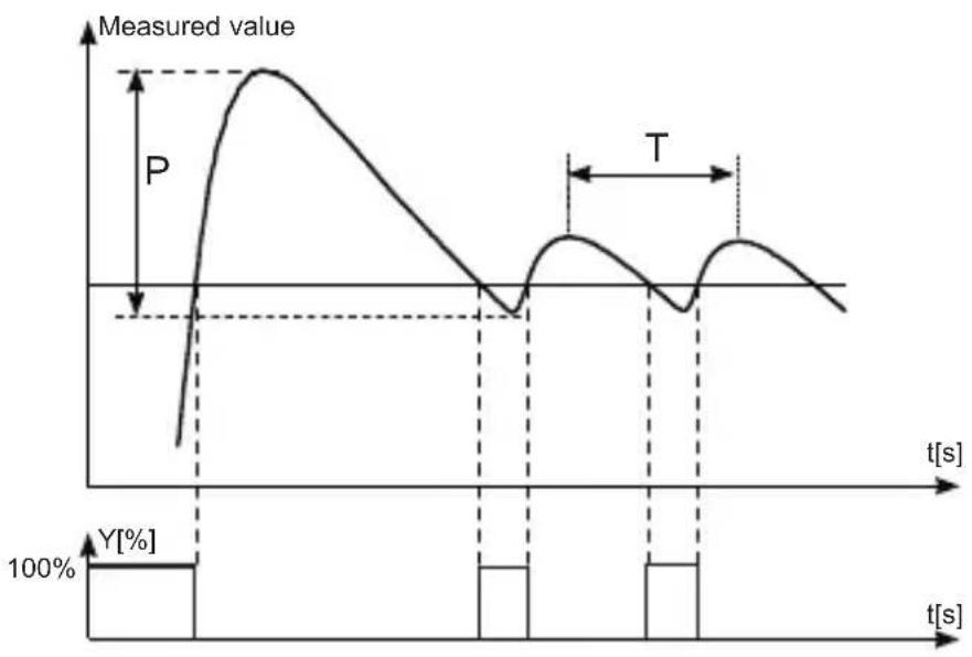
Oscillation method around the set point
Set the ON-OFF control with a minimal hysteresis' Set the set point on a normal work level (or on a lower one' if overshoots would cause damages) and normal load conditions:
line
| t[s] | Measured value | |------|----------------| | 0 | Low | | Peak | High | | T | Medium | | Low | Low | | High | Decreasing |Fig 12 Selection of settings by the oscillation method Calculate controller settings acc to given formulas:
$$ \begin{array}{l} P b = P \ \mathrm{ti} = \mathrm{T} \ \mathrm{td} = 0. 2 5 * \mathrm{T} \ \end{array} $$
Correction of PID settings
Since PID parameters interact between them' one must introduce changes only of one parameter
The best is to choose parameters changing the value into a twice greater or twice smaller one:
During changes' one should be guided by following principles:
a) Slow jump answer:
- decrease the proportional band
- decrease the integration and differentiation time
b) Over-regulations:
- increase the proportional band'
- increase the differentiation time
c) Oscillations:
- increase the proportional band'
- increase the integration time'
- decrease the differentiation time
d) Instability:
- increase the integration time
10' SIGNALLING OF ERRORS
Character messages Table 4
| Error code(upper display) | Reason | Procedure |
| L_Err | Exceeding of the measuring range downwards or short-circuit occurring in the sensor circuit | Check if the type of chosen sensor is in compliance with the connected one:Check if values of input signals are situated in the appropriate rangeIf so' check whether there is no short-circuit in the sensor circuit |
| H_Err | Exceeding of the measuring range upwards or break in the sensor circuit | Check if the type of chosen sensor is in compliance with the connected one:Check if values of input signals are situated in the appropriate rangeIf so' check whether there is no short-circuit in the sensor circuit |
| R_E^r | The auto-tuning has not been finished successfully | Check reasons of breaking the tuning processin auto-tuning point |
| E^rR_d | Discalibrated input | Connect again the controller supply and if it cannot help' contact the nearest authorized service shop |
11' TECHNICAL DATA
Input signals and measuring ranges for sensor inputs
| Sensor type | Standard Notation Range | Symbol | Table 5on the display | |
| Pt100 | EN 60751+A2 Pt100-1 | 99***850°C Pt1 | ||
| Pt1000 | EN 60751+A2 Pt1000-1 | 199***850°C Pt10 | ||
| Fe-CuNi | EN 60584-1 J-100***1 | 200°C t-j | ||
| Cu-CuNi | EN 60584-1 T-1 | 100***400°C t-t | ||
| NiCr-NiAl | EN 60584-1 K-1 | 100***1372°C t-t | ||
| PtRh10-Pt | EN 60584-1 | S | 0***1767°C | t-s |
| PtRh13-Pt | EN 60584-1 | R | 0***1767°C | t-r |
| PtRh30-PtRh6 | EN 60584-1 | B | 0***1820°C* | t-b |
| NiCr-CuNi | EN 60584-1 | E | -100***999°C | t-f |
| NiCrSi-NiSi | EN 60584-1 | N | -100***1300°C | t-p |
| chrome-kopei | GOST R 8'585 | L-100***800°C t-l |
* The measurement error is defined for the range 0…1820°C
Input signals and measuring ranges for
| linear inputs | |||
| Sensor type | Notation | Range | Symbol on the display |
| Linear current input | I | 0 ·s 20 mA | 0-20 |
| Linear current input | I | 4 ·s 20 mA | 4-20 |
| Linear voltage input | U | 0 ·s 5 V 0-5 | |
| Linear voltage input | U | 0 ·s 10 V | 0-10 |
Input signals:
- for sensor inputs
acc to table 5
- for linear inputs
acc to table 6
Basic error of true value measurement:
0.2%' for RTD inputs'
0'3%' for TC inputs (0'5% - for B' R' S)'
0'2% ± 1 digit' for linear inputs
Measurement time:
- for sensor inputs 0.33 s
- for linear inputs 0.16 s
Input resistance:
- for voltage input 150 kΩ
- for current input 4 Ω
Detection of error in the measuring circuit:
- thermocouple' Pt100' PT1000 overrunning of the measuring range
- 0…10 V over 11 V
- 0…5 V over 5'25 V
- 0…20 mA over 22 mA
- 4…20 mA under 1 mA and over 22 mA
Control algorithm: P' PD' PI' PID'
too-state with hysteresis
Range of controller
parameter settings: see table 1
Kind of outputs:
- relay switch over contact
maximal load-carrying capacity:
voltage: 250 V a'c' 150 V d'c'
current: 5 A 250 V a'c' 5 A 30 V d'c
resistance load: 1250 VA' 150 W
- binary voltage (without isolation from the sensor side)
voltage 5 V
resistance limiting the current 66 Ω;
Way of output action:
- reverse for heating
- direct for cooling
Signalling:
- output switching on
- display of set point
- manual control mode
- auto-tuning mode
Rated service conditions:
- supply voltage 230 V a·c· ± 10 %
$$ 110 \mathrm{V} a^{\cdot}c^{\cdot}\pm 10\% $$
$$ 24 \mathrm{V} a^{\cdot}c^{\cdot}\pm 10\% $$
- supply voltage frequency 50/60 Hz
- ambient temperature 0…23…50 °C
- storage temperature -20…+70 °C
- relative air humidity < 85 % (without
一
condensation)
- external magnetic field < 400 A/m
- preheating time 30 min
- work position any
- resistance of wires connecting the resistance thermometer with the controller < 20 Ω
Power consumption < 3 VA
Weight < 0.25 kg
IP protection ensured through the housing: acc' to EN 60529
- from the frontal side IP40
- from terminal side IP20
Additional errors in rated working conditions caused by:
- compensation of the thermocouple cold junction ≤ 2
- ambient temperature change
^o C'
≤ 100% of the basic error value/10 K
Safety requirements acc' to EN 61010-1
- installation category III
- level of pollution 2
- maximal working voltage in relation to ground:
- for supply circuit' outputs
300 V
- for input circuits
50 V
Electromagnetic compatibility:
- immunity acc' to EN 61000-6-2
- emission acc to EN 61000-6-4
12' ORDER CODES
Coding way is given on the table 7. Controller PCE- RE22 - Table 7 X X X XX X
Input
universal for thermocouples and RTD 1
universal linear current 0/4"20 mA'
and linear voltage 0…5/10 V …… 2
on order X
Output
relay 1
binary 0/5 V to SSR control 2
on order X
supply
230 V 50/60 Hz 1
110 V 50/60 Hz 2
24 V 50/60 Hz 3
on order X
Kind of option
standard 00
custom-made* XX
Additional
without a quality inspection certificate 8
with a quality inspection certificate 7
acc to customer's agreement ** X
* The option code is established by the manufacturer
** After agreement with the manufacturer*
Ordering example:
The code: RE22-1-2-3-00-7 means:
RE22 - controller with universal input + 1 output
1 - universal input for RTD and TE
2 - binary output 0/5 V to SSR control
3 - supply: 24 V a·c
00 - standard option
7 - with an extra quality inspection certificate

- CONTROLLER WITH UNIVERSAL INPUT AND 1 OUTPUT PCE- SERIES RE22
- CONTENTS
- 1' APPLICATION
- 2' CONTROLLER SET
- 3' CONTROLLER PREPARATION TO WORK
- 3'1' Safety
- 3'2' Controller installation in the panel
- 3'3' Electrical connections
- 3'4' Installation recommendations
- 4' STARTING TO WORK
- Change of the set point
- 5' PROGRAMMING OF CONTROL PARAMETERS
- 5'1' Scheme of the controller menu
- 5'2' Setting change
- 5'3' List of parameters
- 6' INPUTS AND OUTPUTS OF THE CONTROLLER
- 6'1' Measuring input
- 6'2' Output
- 7° CONTROL
- 7'1' ON-OFF control
- 7'2' PID control
- 8' ADDITIONAL FUNCTIONS
- 8'1' Display of the control signal
- 8'2' Manual control
- 8'3' Controller reaction (response) after the sensor damage
- 8'4' Rate of the set point change - soft-start
- 8'5' Manufacturer's settings
- 9' SELECTION OF PID PARAMETER SETTINGS
- 9'1' Auto-tuning
- 9'2' Manual selection of PID parameter settings Method of response to a unitary jump
- Oscillation method around the set point
- Correction of PID settings
- 10' SIGNALLING OF ERRORS
- 11' TECHNICAL DATA
- Input signals:
- Basic error of true value measurement:
- Measurement time:
- Input resistance:
- Detection of error in the measuring circuit:
- Range of controller
- Kind of outputs:
- Way of output action:
- Signalling:
- Rated service conditions:
- IP protection ensured through the housing: acc' to EN 60529
- Additional errors in rated working conditions caused by:
- Safety requirements acc' to EN 61010-1
- Electromagnetic compatibility:
- 12' ORDER CODES
- Input
- Output
- supply
- Kind of option
- Additional
- Ordering example:
Brand : PCE Instruments
Model : RE22T
Category : Regulator