
SI Series S210 - Audio HK AUDIO - Free user manual and instructions
Find the device manual for free SI Series S210 HK AUDIO in PDF.


| Product Type | 2x10" Subwoofer (S210 V and S210 P variants) |
| Model Variants | S210 V: Bass reflex port, IP44; S210 P: Passive radiators, IP66 |
| Protection Class (S210 V) | IP44 according to EN 60529 (dust and splash water protection) |
| Protection Class (S210 P) | IP66 according to EN 60529 (dust-tight and heavy water jet protection) |
| Ball Impact Proof | Certified per DIN 18032-3 for sports facilities |
| Impedance | Switchable: 4 Ω or 16 Ω per speaker |
| Connectors | Two 4-pole connectors, wired in parallel |
| Mounting Options | Wall (perpendicular/parallel), ceiling, flown using U-bracket; extension plate for dual S210 |
| Included Accessories | Cover plate with PG glands, sealing material (Isozell), M8 rosettes |
| Recommended Satellite Speakers | SI SERIES P10 (recommended ratio: S210 V:P10 = 1:2, S210 P:P10 = 1:1) |
| Built-in Filters | Low-pass at 140 Hz (for P10), low-pass at 100 Hz (universal), No DSP preset |
| Application Areas | S210 V: indoor and covered outdoor; S210 P: indoor and unprotected outdoor, sports facilities |
| Safety Compliance | WARNING: hearing protection required above 95 dBA SPL; annual inspection of rigging |
| Max Torque (Cover Plate Screws) | Outer screws: 2.6 Nm, inner screws: 1 Nm |
| Threadlocking Recommendation | Use threadlocking adhesive on all screw connections for long-term stability |
| Cable Requirements | Only round-sheathed speaker cables; use gas-tight crimped wire ends |
| Environmental Conditions | S210 V: light dust/dirt and splash water; S210 P: strong dust/dirt and water jets |
| U-Bracket Usage | Attach to outer holes only; central hole for cable feed-through only |
| Flown Installation | Limited to fixed installation in wind-protected areas; use M12 ring bolts (DIN 580) |
Frequently Asked Questions - SI Series S210 HK AUDIO
User questions about SI Series S210 HK AUDIO
0 question about this device. Answer the ones you know or ask your own.
Ask a new question about this device
Download the instructions for your Audio in PDF format for free! Find your manual SI Series S210 - HK AUDIO and take your electronic device back in hand. On this page are published all the documents necessary for the use of your device. SI Series S210 by HK AUDIO.
USER MANUAL SI Series S210 HK AUDIO


- Operating and Installation Instructions 1.0
General Notes on Safety for Loudspeaker Systems

Mounting systems may only be used for those loudspeaker systems authorized by the manufacturer and only with the mounting accessories specified by the manufacturer in the installation instructions. Read and heed the manufacturer's installation instructions. The indicated load-bearing capacity cannot be guaranteed and the manufacturer will not be liable for damages in the event of improper installation or the use of unauthorized mounting accessories.
The system's load-bearing capacity cannot be guaranteed and the manufacturer will not be liable for damages in the event that loudspeakers, mounting accessories, and connecting and attaching components are modified in any way.
Components affecting safety may only be repaired by the manufacturer or authorized agents, otherwise the operating permit will be voided.

Installation may be performed by qualified personnel only, and then only at pick-points with sufficient load-carrying capacity and in compliance with local building regulations. Use only the mounting hardware specified by the manufacturer in the installation instructions (screws, anchors, etc.). Take all the precautions necessary to ensure bolted connections and other threaded locking devices will not loosen.

Fixed and portable installations (in this case, speakers and mounting accessories) must be secured by two independent safeties to prevent them from falling. Safeties must be able to catch accessories or parts that are loose or may become loose. Ensure compliance with the given national regulations when using connecting, attaching, and rigging devices. Factor potential dynamic forces (jerk) into the equation when determining the proper size and load-bearing capacity of safeties.

Be sure to observe speaker stands' maximum load-bearing capacity. Note that for reasons of design and construction, most speaker stands are approved to bear centric loads only; that is, the speakers' mass has to be precisely centered and balanced. Ensure speaker stands are set up stably and securely. Take appropriate added measures to secure speaker stands, for example when:
- the flour or ground surface does not provide a stable, secure base.
- they are extended to heights that impede stability.
- high wind pressure may be expected.
- there is the risk that they may be knocked over by people.
Special measures may become necessary as precautions against unsafe audience behavior. Do not set up speaker stands in evacuation routes and emergency exits. Ensure corridors are wide enough and put proper barriers and markings in place when settling speaker stands up in passageways. Mounting and dismounting are especially hazardous tasks. Use aids suitable for this purpose. Observe the given national regulations when doing so.


Wear proper protection (in particular, a helmet, gloves, and safety suitable means of ascent (ladders, scaffolds, etc.) during installation. requirement is the sole responsibility of the company performing the

WARNING: After installation, inspect the system comprised of the mounting fixtures and loudspeakers to ensure it is properly secured. The operator of loudspeaker systems (fixed or portable) must regularly inspect or task a third party to regularly inspect all system components in accordance with the given country's regulations and have possible defects repaired immediately. The inspection interval of the recurring inspection must not exceed an annual period. We also strongly recommend maintaining a logbook or the like to document all inspections.
Also be sure to provide sufficient safety margins for the rigging points used for flown systems. Observe the given national regulations when doing so.

Professional loudspeaker systems can produce harmful volume levels. Even prolonged exposure to seemingly harmless levels (starting at about 95 dBA SPL) can cause permanent hearing damage! Therefore we recommend that everyone who is exposed to high volume levels produced by loudspeaker systems wears professional hearing protection (earplugs or earmuffs).
Manufacturer: Stamer Musikanlagen GmbH, Magdeburger Str. B, 66606 St. Wendel, Germany
Version 2.9b 03/2021

- Please keep these instructions for later use during installation or make them available to the specialist company carrying out the installation!
- The use of threadlocking adhesives is recommended for all screw connections in order to guarantee a stable connection in the long term.
- In principle, a sufficiently load-bearing surface and a suitable connection method must be ensured for all installations. This is the responsibility of the specialist company carrying out the installation. In case of doubt, qualified advice (e.g. from engineering consultants/staticians) must be sought.
- All loudspeakers must be inspected for damage and signs of wear at regular intervals appropriate to the respective installation site and its environmental conditions. This applies especially to installations outside protected premises and in particular under demanding environmental conditions.
• Examples of possible damage or signs of wear include the ingress of water or dust into critical areas of the enclosure such as the electrical connections or the mechanically sensitive areas of the transducers, rust or mechanical damage to the metal surfaces/ grids/screws, and cracks or other damage to the paint finish. - If damage of this or similar nature is found, the speaker must be dismantled and repaired.

Contents
1 Loudspeaker Types 4
2 Mechanical Accessories 7
2.1 U-Bracket....7
2.2 Extension Plates for U-Bracket....7
3 Application Guide 8
3.1 Basic Use of S210 Subwoofers 8
3.2 Permitted Areas of Use and Environmental Conditions 8
3.3 Basic Filters for various Loudspeaker Combinations....9
4 Electrical Connections....10
4.1 Electrical Connections for S210 V und S210 P 10
4.2 Mounting the Cover Plate 10
4.3 Service and Disassembly of the Cover Plate 11
4.4 Connecting multiple S210 V or S210 P
to one Power Amplifier Channel 12
5 Mounting Instructions for Mechanical Accessories 13
5.1 Mounting Points in S210....13
5.2 U-Bracket for S210 14
5.3 Extension Plates for U-Bracket....15
5.4 U-Bracket - Mounting perpendicular to a Wall....15
5.5 U-Bracket - Mounting parallel to a Wall 18
5.6 U-Bracket - Mounting on a Ceiling 19
5.7 U-Bracket - Assembly for flown fixed Installation 21
5.8 Using the Extension Plates in Combination with U-bracket....22

1 Loudspeaker Types
Two variants of the S210 loudspeaker are available within the SI SERIES:

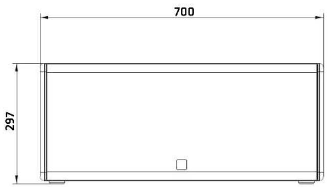
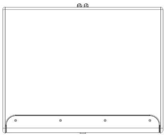
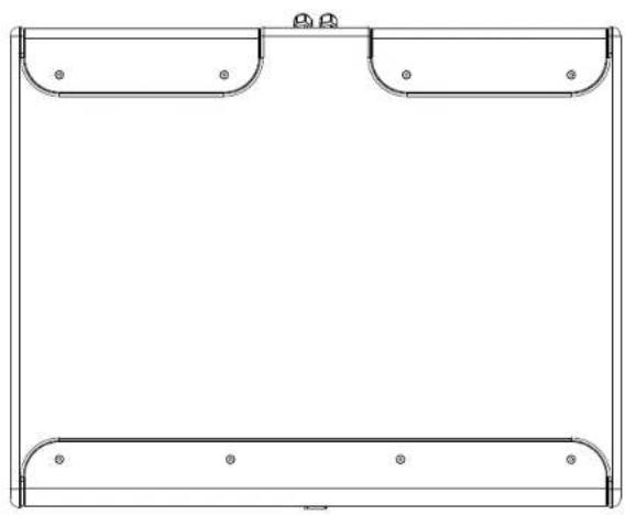
• S210 V
a 2x10 1 subwoofer with large bass reflex port. IP 44 protection class, numerous mounting options and accessories as well as switchable electrical impedance

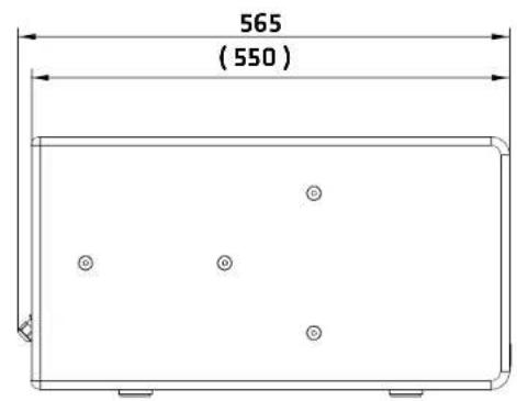
• S210 P
a 2x10" subwoofer with two additional 10" passive radiators, very high protection class IP 66, numerous mounting options and accessories as well as switchable electrical impedance

• S210 V


-5-
• S210 P


-6-
2 Mechanical Accessories
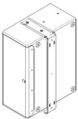
The mounting accessories available for SI SERIES S210 are applicable for both S210 V and S210 P (see 1). It is shown below in the component overview.

Caution: Only original HK Audio mountingories may be used to install the speakers.
2.1 U-Bracket
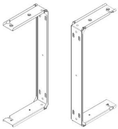
Using the U-bracket, 5210 subwoofers can be mounted on walls and ceilings as well as flown.
2.2 Extension Plates for U-Bracket

If two 5210 subwoofers are to be mounted on the U-bracket, these extension plates are required for mounting the second subwoofer. This set consists of two extension plates and two shim plates.

3 Application Guide
3.1 Basic Use of S210 Subwoofers
The S210 V and S210 P subwoofers are suitable for a wide range of sound reinforcement applications. In particular, they are suitable for combination with the modular extendable SI SERIES P10 loudspeakers for installations under acoustically or with regard to their environmental conditions demanding conditions.
Basically, we recommend the following quantity ratio:
- S210 V: P10 = 1:2
- S210 P : P10 = 1 : 1
However, this ratio does not have to apply in every individual case, but depends significantly on the room acoustics. the required maximum sound pressure levels, the user requirements and many other aspects.
As a matter of principle, we recommend performing acoustic simulations during the planning phase using suitable software (EASE 4.4, EASE Focus 3). This is the only way to plan the necessary quantities and the optimal positioning/alignment of the S210 loudspeakers with good certainty.

3.2 Permitted Areas of Use and Environmental Conditions
The S210 V subwoofer is specified with protection class IP 44 according to EN 60529. Thus, the range of application includes all indoor areas, but also covered and roofed outdoor areas. The S210 V may be exposed to light dust/dirt loads and splash water.
The S210 P subwoofer, on the other hand, is specified with protection class IP 66 according to EN 60529. The conformity was confirmed by a test of an independent institute (TÜV SÜD Product Service GmbH). This results in an extended area of application, which allows installation in unroofed and unprotected outdoor areas in addition to all indoor areas. The S210 P may be exposed to strong dust/dirt loads as well as heavy loads from water.
In combination with the SI SERIES P10, the S210 P allows the composition of a complete system with the very high protection class IP 66.
Thus, installation projects can be realised even under the most difficult environmental conditions without having to compromise on the attainable audio quality.
All S210 subwoofers are also certified as ball impact proof according to DIN 18032-3. This was confirmed by testing of an independent institute (Materialprüfungsanstalt Universität Stuttgart). Therefore, the S210s may be installed in sports facilities with the loads typically encountered there.

3.3 Basic Filters for various Loudspeaker Combinations
Basically, the S210 are designed as neutral sound reinforcement tools and can be used with many different satellite speakers. However, they are particularly suitable for combination with the modular extendable SI SERIES P10 loudspeakers. These possibilities are taken into account by a range of preset basic filters on the acoustic side.
The filters are available both as ready-made preset files based on Lab.gruppen IPD and Lake, Powersoft Armonia+ and as an open table format (the latter based on Lab.gruppen IPD).
Basic filters with the following nomenclature are offered:
| S210 System S210 100 Hz S210 No DSP | ||
| Low pass at 140 Hzfor combinationwith SI SERIES P10 | Low-pass filter at 100 Hzfor universal usewith any satellite speakers | Without any filtering,for application-specificadjustments |
All the above-mentioned basic filters are also included in the simulation data in GLL format and can be used for the acoustic simulations recommended in 3.2.
In addition, a "No DSP" preset can be set in the simulation data, with which the expert user can also define application-specific filters.
This option is intended exclusively for professional users with in-depth knowledge of loudspeaker technology. In case of doubt, it is essential to seek the assistance of the manufacturer and/or a professional acoustician with practical sound reinforcement experience.
Caution: Incorrect operation, such as improper filtering, can lead to irreparable mechanical damage to the transducers!
![SI SERIES S210 P Show: Reading Type: Direct GPs (Z) Frequency: 10 Hz Bandwidth: 3 Octenna Adjusted: Avg. A3-91 Object Properties System Parameters Model: S210 P Label: S210 P Position & Orientation X [Hz]: 33.24 Var. (°): 0.00 Y [Hz]: 8.66 Var. (°): 0.00 Z [Hz]: 0.30 Var. (°): 0.00 Height Unit Filte…](/content/2026/05/913596/images/29c94fc7f3ec38a040155852978aebd999db09976b174f7ed5aedb97e7c42df5.jpg)

4 Electrical Connections
The following section describes how to make the electrical connections and how to mount the cover plate.

Caution! The manufacturer's specification of protection classes IP 44 resp. IP 66 (529) for the overall construction only applies if the instructions in this section are ed during installation.
4.1 Electrical Connections for S210 V und S210 P
Two 4-pole connectors are available for wiring the S210 V or S210 P. These always have two poles and are electrically connected in parallel.
Before starting the cabling, the speaker cable (not yet stripped) must be pushed through the opened PG gland of the enclosed cover plate. Further notes on mounting the cover plate in 4.2.

Only one conductor may be connected to each clamping point. It is not permissible to insert several conductors into the same clamping point, as these are not designed for this and could become loose in the long term.

As a general rule, we recommend that all connection cables be provided with (gas-tight) crimped wire and sleeves to prevent the oxidation of the conductors in the long term. Non-crimped (bare) conductors form an oxide layer in the long term, which worsens the contact resistance at the terminals. In practice, it has proven useful to connect one connection cable per connector, because this makes the actual assembly more convenient in confined spaces or when the cables are pulled in different directions. However, all conductors can also be inserted to only one connector, as they are electrically connected in parallel (as described above).
4.2 Mounting the Cover Plate
As described in 4.1, the connecting cable must be pushed through the opened PG gland(s) before making the electrical connections. The sealing material (Isazell) enclosed with the cover plate must be glued all around in the areas provided for this purpose on the back before installation. Make sure that it is glued neatly. Under no circumstances may the sealing material protrude to the side and/or be visible from the outside.

Note: It is not permissible to apply the sealing material (Isozell) directly to the enclosure. This will result in a lack of tightness.

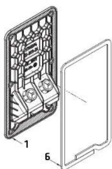


pos. description qty.
| 1 cover plate 1 | |
| 2 4-pole connectors 2 | |
| 3 outer MS countersunk screws 4 | |
| 4 connection cable - x | |
| 5 inner MS countersunk screws 2 | |
| 6 sealing material (Isozell) 1 |
* Not included in delivery
As standard, the cover plate is provided with a sealing plug in one of the two PG glands. If the S210 loudspeaker is to be connected with only one cable, the sealing plug must remain in the PG gland. If a second cable is to be used (e.g. to connect another loudspeaker connected in parallel), the sealing plug must be removed accordingly for the cable feed-through.
Basically, only speaker cables with a round sheathing may be used. Individually insulated speaker cables would create a gap in the PG gland through which dust or water could penetrate.
The cover plate must be screwed crosswise and with gradually increasing torque. Under no circumstances may the cover plate lift at a corner or form a bulge along one side, as otherwise sufficient tightness cannot be guaranteed.
Caution! The maximum torque for tightening the outer screw connections of the cover plate is 2.6 Nm, for the inner screw connections the maximum torque is 1 Nm.
4.3 Service and Disassembly of the Cover Plate
If the cover plate has been removed for service purposes, it is essential to renew the sealing material (Isozell), as it will no longer seal properly after being compressed once. Care must be taken to ensure that the renewed Isozell is bonded to a clean surface, as its tightness could otherwise be impaired. We generally advise against the use of silicone/acrylic or similar substances instead of the Isozell, as it may be impossible to dismantle the cover plate for service purposes using such sealants.

4.4 Connecting multiple S210 V or S210 P to one Power Amplifier Channel
The electrical impedance of the S210 can be switched between 4 ohms or 16 ohms. The switch integrated into the connection panel is recessed. It is best operated with a small tool.
With the help of this adjustable electrical impedance, individual or several S210s can be combined in such a way that the amplifier used in each case can be optimally utilised.
The manufacturer's specifications of the respective amplifier manufacturer or the project-specific planning documents incl. the respective wiring system apply.
The following equations apply to determine the connected total load:
- Equation for parallel connection:
R _ total = 1( 1R _ 1) + ( 1R _ 2) + ( 1R _ 3) + ... ( 1R _ n)
Example #1:
Connecting two S210s in parallel with the switch set to "4 ohms" results in a connected load of 2 ohms.
R _ total = 1/(1/4 Ω) + (1/4 Ω) = 2 Ω

Example #2:
Connecting two 5210 in parallel with the switch set to "16 ohms" results in a connected load of 8 ohms.
R _ total = 1/(1/1 6 Ω) + (1/1 6 Ω) = 8 Ω

Note: In principle, we recommend that all 5210s operated on the same power amplifier channel use the same switch setting (either 4 ohms or 16 ohms). Mixing different switch positions is not recommended, as this leads to an undesired shift of the level ratios.
For justified exceptions, it is essential to seek the assistance of the manufacturer and/or a professional acoustician with practical experience in sound reinforcement.

5 Mounting Instructions for Mechanical Accessories

Caution: The following installation instructions for the mechanical accessories apply only to use with the 5210 speakers. Only original HK Audio accessories may be used. Care must be taken to use suitable tools to carry out the installation. The general safety instructions apply.
5.1 Mounting Points in S210
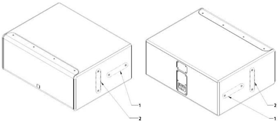
1.) All S210s have mounting points inside the enclosure as standard. These are exclusively for mounting the optional U-bracket (see 5.7).
2.) The two mounting points parallel to the front (see position 2) are located in the centre of gravity of the enclosure, which facilitates the mounting of the optional U-bracket and many subsequent mounting steps.
3.) The M8 countersunk screws located in the enclosure are basically available for operation. Further details are explained in the following sections.
| pos. description qty. | |
| 1 Mounting points for:mounting perpendicular to the wall, for max. 1x S210 | 2 |
| 2 Mounting points for:mounting parallel to the wall, for max. 1x S210ceiling mounting, for max. 2x S210flown installation for max. 2x S210 | 2 |

5.2 U-Bracket for S210


1.) The U-bracket for S210 can be attached vertically or horizontally to the speaker enclosure.
2.) Basically, the U-bracket is mounted with the M8 countersunk screws in the speaker enclosure. Suitable M8 rosettes are included in the delivery.
Intended use
The U-bracket is intended exclusively for the fixed installation of SI SERIES S210 speakers and not for the installation of other (HK Audio) products.
Before each use, all mechanical components must be checked by an instructed person for visible damage, wear, functionality, apparent operational safety and legibility of markings. Only flawless and undamaged components may be used for installation. Damaged components or components that are not in perfect condition for other reasons must be dismantled and repaired professionally.
When moving, e.g. lifting or lowering as part of assembly or dismantling, staying under the speakers is prohibited. To avoid overloading the components, lifting must be implemented without jerks and with a travel speed of <0.2 m/s.
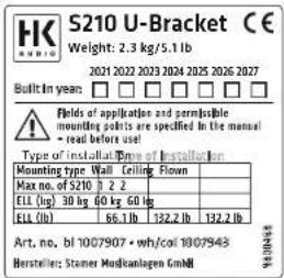

Non-observance of the specifications can lead to
uncontrolled movements or to system components or the entire loudspeaker system falling down.
The consequences can be serious or even fatal injuries.

Caution: It is important to remember that all screw connections on subwoofers are subject to considerable mechanical vibration forces during operation and can loosen without suitable safety measures.
A possible loosening of the screw connections not only leads to possible rattling noises during operation, but can also be a safety-critical aspect due to the decreasing pretensioning force.
The choice of the appropriate assembly method (e.g. with the aid of thread locking adhesive, RIPP LOCK washers, etc.) depends on the environmental conditions of the respective installation and is the responsibility of the specialist company carrying out the work.
Note: If the screw connections are insufficiently executed, the ball impact safety certificate according to DIN 18032-3 is invalid. Therefore, please always ensure correct assembly based on these instructions.

Caution: There are a total of four M5 screws with self-locking cap nuts in the joints of the U-bracket. Do not remove these screws under any circumstances! The screws must be checked for presence and tightness during the inspection.

5.3 Extension Plates for U-Bracket S210

1.) If two 5210 subwoofers are to be mounted or flown together on a ceiling, the extension plates are used.
2.) There are always two extension plates and two shim plates in a set.
| pos. description qty. | ||
| 1 Extension plate 2 | ||
| 2 Shim plate 2 | ||
5.4 U-Bracket - Mounting perpendicular to a Wall

1.) Mount the U-bracket on a suitable surface, e.g. a wall.
2.) The choice of a suitable mounting method depends on the conditions of the respective installation and is the responsibility of the specialist company carrying out the installation.
3.) Remove the M8 countersunk screws from the speaker enclosure.
4.) First, the two front screws must be fitted with the rosettes that are included with the delivery of the U-bracket. These rosettes adhere to the screw thread and do not slip during the following assembly steps.
5.) The screws fitted with the rosettes must now be pre-assembled in the enclosure. To do this, they should only be screwed a few millimetres into the speaker enclosure.

6.) The subwoofer can now be pushed onto the U-bracket.
7.) The pre-mounted screws are caught by the hook-shaped openings in the bracket and the subwoofer is immediately secured against slipping off during this mounting phase.


Detail

8.) It is recommended to hand tighten the two pre-assembled screws immediately after inserting them into the hook openings.
9.) In the next step the two rear screws, which are also to be fitted with the rosettes, can be inserted into the rear openings of the bracket and screwed to the speaker enclosure.
10.) Afterwards, all screws must be tightened crosswise with gradually increasing torque until the bracket is firmly connected to the speaker.
pos. description qty.
| 1 U-bracket 1 | |
| 2 M8 countersunk screw 4 | |
| 3 M8 rosette 4 |


5.5 U-bracket - Mounting parallel to a Wall
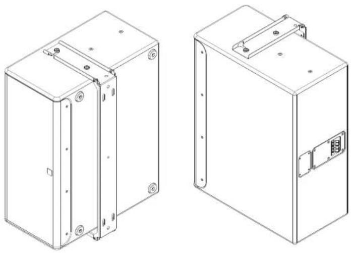
1.) The assembly of the U-bracket parallel to a wall does not differ in principle from the assembly perpendicular to a wall, which is why the same assembly steps as in 5.4 are to be used for this.
2.) However, instead of the two rear mounting points, the two front mounting points (see 5.1) of the speaker enclosure must be used.
3.) It is recommended to position the loudspeaker enclosure so that the rubber feet are not facing towards the audience area.
| pos. description qty. | ||
| 1 U-bracket 1 | ||
| 2 M8 countersunk screw 4 | ||
| 3 M8 ripsette 4 | ||
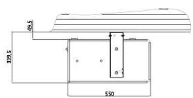
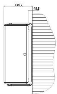

5.6 U-Bracket - Mounting on a Ceiling
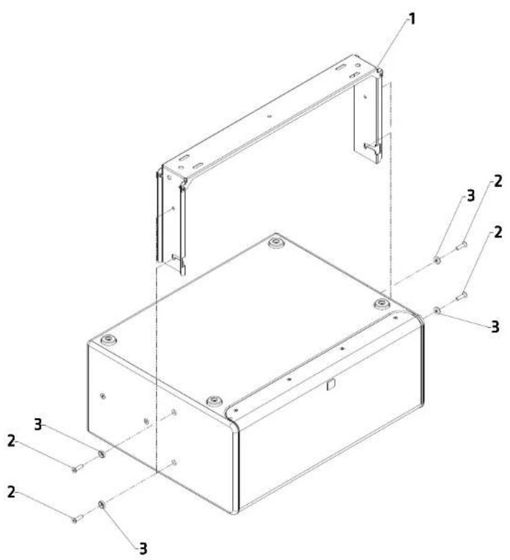
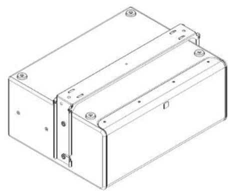
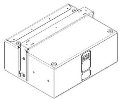

1.) Mount the U-bracket on a ceiling or another surface with sufficient load-bearing capacity for overhead mounting (e.g. a steel beam or truss system).
2.) The choice of the appropriate mounting method depends on the conditions of the respective installation and is the responsibility of the specialist company carrying out the installation.
3.) Remove the M8 countersunk screws from the speaker enclosure.
4.) First, the two front screws must be fitted with the rosettes that are included with the delivery of the U-bracket. These rosettes adhere to the screw thread and do not slip during the following assembly steps.
5.) The screws fitted with the rosettes must now be pre-assembled in the enclosure. To do this, they should be screwed a few millimetres into the speaker enclosure.
6.) The subwoofer can now be hooked into the U-bracket.
7.) The pre-mounted screws are caught by the hook-shaped openings in the bracket and the subwoofer is immediately secured against slipping off during this mounting phase.

Detail
8.) It is recommended to hand-tighten the two pre-assembled screws immediately after inserting them into the hook openings.
9.) In the next step the two rear screws, which are also to be fitted with the rosettes, can be inserted into the rear openings of the bracket and screwed to the speaker enclosure.
10.) Afterwards, all screws must be tightened crosswise with gradually increasing torque until the bracket is firmly connected to the speaker.

pos. description qty.
| 1 U-bracket 1 | |
| 2 M8 countersunk screw | 4 |
| 3 M8 rosette | 4 |


Caution: All mounting materials may only be
attached to the two outer holes of the U-bracket. The hole in the middle is used e.g. for a cable feed-through or securing, but must not be used for carrying the speakers.

5.7 U-Bracket - Assembly for flown fixed Installation


-21-
1.) The procedure for mounting the U-bracket to the speaker enclosure is no different from previous instructions, see 5.6.
2.) We recommend the use of M12 ring bolts (DIN 580 or equivalent), which can be fastened to the U-bracket with self-locking cap nuts and, if necessary, an additional RIPP LOCK washer. Depending on the mounting situation, it may be practical to first mount these to the U-bracket before connecting it to the loudspeaker.
3.) The range of use of flown S210 subwoofers is limited to fixed installation in wind protected areas. Other areas and purposes of use are not permitted.

Caution: All mounting materials may only be attached to the two outer holes of the U-bracket. The central hole is used, for example, for a cable feed-through or securing, but must not be used to support the speakers.

Caution: Diagonal pull on the two outer attachment points by bridles or Y-shaped slings is not permitted for flown installations.
| pos. description qty. | ||
| 1 U bracket 1 | ||
| 2 M8 countersunk screw 4 | ||
| 3 M8 rosette 4 | ||
| 4 M12 ring bolt (DIN 580:2018, WLL = 340 kg or equivalent) | -* | |
| 5 M12 gap nut, self-locking | -* | |
* Not included in delivery
5.8 Using the Extension Plates in Combination with U-bracket

1.) The extension plates are basically supplied as a set consisting of four parts (see 5.3). They are used whenever two S210s are to be installed on the ceiling or for a flown installation.
2.) The shim plates serve as height compensation. To do this, they must be placed on the lower speaker, with the U-bracket placed on the upper speaker.
3.) The extension plates must then be placed over the resulting surface with the same height.
4) The following screw connections must be made through both the U-bracket and the two plates.
5.) As with all other previous assembly instructions (see 5.4), the M8 screws with the M8 rosettes located in the loudspeaker enclosure must be used for this.
6.) The described mounting of the extension plates is applicable to both ceiling mounting with max. two S210 and flown installation with max. two S210.

Caution: All mounting materials may only be attached to the two outer holes of the U-bracket. The central hole is used, for example, for a cable feed-through or securing, but must not be used to support the speakers.

Caution: Diagonal pull on the two outer attachment holes by bridles or Y-shaped slings is not permitted for flown installations.


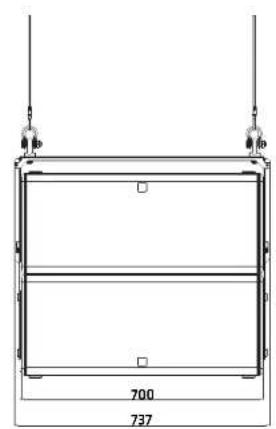


| pos. description qty. | ||
| 1 U-bracket 1 | ||
| 2 Extension plate 2 | ||
| 3 Shim plate 2 | ||
| 4 M8 rosette 4 | ||
| 5 M8 countersunk screw 4 | ||
| 6 M12 ring bolt (DIN 580:2018,WLL = 340 kg or equivalent) | - * | |
| 7 M12 lap nut, self-locking - * | ||
* Not included in delivery

SI SERIES S210

HK Audio ® • Postfach 1509 • 66595 St. Wendel • Germany • info@hkaudio.com • www.hkaudio.com
International Inquiries: fax +49-68 51-905 215 • international@hkaudio.com

- GENERAL NOTES ON SAFETY FOR LOUDSPEAKER SYSTEMS
- CONTENTS
- 1 LOUDSPEAKER TYPES
- S210 V
- S210 P
- 2 MECHANICAL ACCESSORIES
- 3 APPLICATION GUIDE
- 3.1 BASIC USE OF S210 SUBWOOFERS
- 3.2 PERMITTED AREAS OF USE AND ENVIRONMENTAL CONDITIONS
- 3.3 BASIC FILTERS FOR VARIOUS LOUDSPEAKER COMBINATIONS
- 4 ELECTRICAL CONNECTIONS
- 4.1 ELECTRICAL CONNECTIONS FOR S210 V UND S210 P
- 4.2 MOUNTING THE COVER PLATE
- 4.3 SERVICE AND DISASSEMBLY OF THE COVER PLATE
- 4.4 CONNECTING MULTIPLE S210 V OR S210 P TO ONE POWER AMPLIFIER CHANNEL
- EXAMPLE #1
- EXAMPLE #2
- 5 MOUNTING INSTRUCTIONS FOR MECHANICAL ACCESSORIES
- 5.1 MOUNTING POINTS IN S210
- 5.2 U-BRACKET FOR S210
- INTENDED USE
- 5.3 EXTENSION PLATES FOR U-BRACKET S210
- 5.4 U-BRACKET - MOUNTING PERPENDICULAR TO A WALL
- 5.5 U-BRACKET - MOUNTING PARALLEL TO A WALL
- SI SERIES S210
Brand : HK AUDIO
Model : SI Series S210
Category : Audio