V-Joy+ - Uncategorized Telycam - Free user manual and instructions
Find the device manual for free V-Joy+ Telycam in PDF.


| Product Type | Joystick Controller |
| Brand | Telycam |
| Model | V-Joy+ |
| Dimensions (W x D x H) | 180 x 150 x 90 mm |
| Weight | 0.85 kg |
| Power Supply | 12V DC, 1A (adapter included) |
| Communication Ports | RS-232, RS-485, USB 2.0 |
| Supported Protocols | VISCA, Pelco-D, Pelco-P |
| Control Functions | Pan, Tilt, Zoom, Focus, Iris, Preset Recall |
| Joystick Type | 3-axis with variable speed |
| Display | 2.8-inch TFT LCD |
| Programmable Keys | 12 (customizable) |
| Preset Memory | Up to 255 presets |
| Camera Addresses | Supports up to 7 cameras |
| Mounting | Desktop or rack mount (kit optional) |
| Operating Temperature | 0°C to 40°C |
| Included Items | Joystick, power adapter, USB cable, user manual |
| Certifications | CE, FCC |
| Material | ABS plastic |
| Color | Black |
| Warranty | 1 year limited |
| Compatibility | PTZ cameras with VISCA/Pelco protocols |
Frequently Asked Questions - V-Joy+ Telycam
User questions about V-Joy+ Telycam
0 question about this device. Answer the ones you know or ask your own.
Ask a new question about this device
Download the instructions for your Uncategorized in PDF format for free! Find your manual V-Joy+ - Telycam and take your electronic device back in hand. On this page are published all the documents necessary for the use of your device. V-Joy+ by Telycam.
USER MANUAL V-Joy+ Telycam
IP&Serial Joystick Remote Control Keyboard
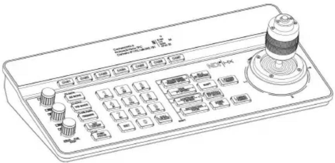
User Manual
V2.0
1. Security Guidance....2
1.1 Cautions....2
1.2 Notice....2
2. Check Before Using....3
2.1 Packing List....3
2.2 The Wiring....3
2.3 Bottom Dialing Switch....3
3. Keyboard Description....4
3.1 Functional Features....4
3.2 Technical Specifications....5
3.3 Product Size....5
3.4 Interface Description....6
3.5 Display Screen Content....6
3.6 Button Function....7
4. Menu Setting....11
4.1 Operating Instructions....11
4.2 Menu options....11
5. Wiring diagram....13
5.1 Connection in network mode....13
5.2 Connection in RS232 mode....14
5.3 Connection in RS422 mode....15
5.4 Connection in RS485 mode....15
5.5 Cascade in RS232, RS422, RS485 mode....16
6. WEB Configuration....18
6.1 Login WEB....18
6.2 Device Control....18
6.3 Network Paramete....19
6.4 Firmware Upgrade....19
6.5 Reset Options....19
6.6 Account....20
7. Frequently Asked Questions....21
1.1 Cautions:
● Before using the product, please read this safety instruction carefully, operate strictly in accordance with the instruction manual, and keep this manual properly for future reference.
- The standard power supply voltage is DC 12V and the rated current is 1A. recommended to use with the power adapter that comes with the product.
- Please place the power cable and control cable in a place where they will not trampled on, and protect the cable, especially the connection part must be firm.
- Please use this product within the allowable temperature and humidity range. Operating temperature: -10^ 50^ , humidity ≤ 80% .
- Do not spill liquids, especially corrosive liquids, on this product to prevent danger.
- Please don't put heavy pressure, violent vibration and immersion during transportation, storage and installation to avoid damaging the product.
- Please do not disassemble this product without permission, there are no parts inside the machine that can be repaired by the user, please leave the work to qual maintenance personnel.
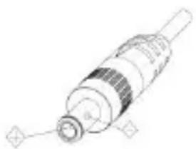
● Power supply polarity
natural_image
Technical line drawing of a mechanical component with no visible text or symbols1.2 Notice:
Please refer to the actual product, the user manual is for reference only.
■ Please contact our Customer Service Department for the latest procedures and additional documentation.
In case of doubt or dispute in the user manual, the final interpretation of the company shall prevail.
2. Check Before Using
2.1 Packing List
When opening the package, please check and confirm all the accessories that should be provided.
Control keyboard 1PCS
Power Adapter 1PCS
Power Cord 1PCS
RS232 Cord 1PCS
User Manual 1PCS
Certificate of Conformity 1PCS
Warranty Card 1PCS
Quick Guide 1PCS
2.2 The Wiring
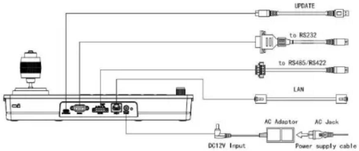
flowchart
graph TD
    A["Power supply cable"] --> B["DC12V Input"]
    B --> C["AC Adaptor"]
    C --> D["LAN"]
    D --> E["to RS485/RS422"]
    E --> F["to RS232"]
    F --> G["UPDATE"]
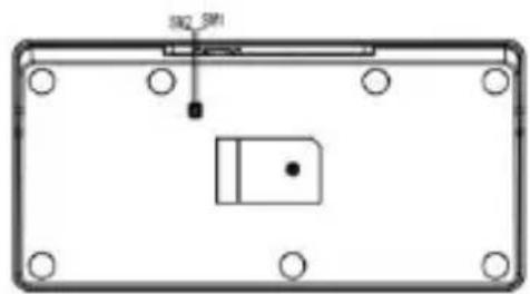
2.3 Bottom Dialing Switch
natural_image
Pure electrical circuit lines without any symbols| Bottom dial control | |||
| Mode | SW-1 | SW-2 | Description |
| 1 | * | OFF | ARM Upgrade Mode |
| 2 | * | ON | Normal Working Mode |
| SW-1 is reserved, no function defined | |||
3.1 Functional Features:
★ Support network interface, RS232 interface, RS422 interface and RS485 interface for control.
★ Supports VISCA Serial, Pelco-P, Pelco-D, VISCA over IP, VISCA TCP, VISCA UDP, ONVIF, and NDI protocols for control. (NDI protocol is optional.)
★ With seven camera shortcut control buttons, to improve the speed of multiple cameras control switching, convenient and fast.
★ Support setting different protocols to control multiple cameras with different protocols.
★ Support one keyboard to control multiple cameras, also support multiple keyboards to control a camera through the network interface.
★ Adapts four-dimensional joystick to enable the control of the video camera PTZ movement smoothly and flexibly.
★ Support to set different levels of operation permission via OSD menu.
★ Support button keys backlight, enable users to choose automatic backlight in low light or dark environment.
★ Support set, call and clear presets.
★ Support camera PT speed and zoom speed adjustment, while supporting preset position PT speed and zoom speed adjustment.
★ Support daisy chain function. (Max 7 cameras are available)
★ Support camera OSD menu setting.
★ Supports standard POE (Power Over Ethe).
★ Support 10M, 100M adaptive network RJ45 connection.
★ Support both Chinese and English menu interface.
4. Menu Setting
3.2 Technical Specifications:
| Parameters | Indicators |
| Control Interface | RJ45,RS232,RS422,RS485 |
| RJ45 | Ethernet port, POE (IEEE802.3af) |
| RS232 | DB9 male connector |
| RS422 | 3.81 spacing terminal, T+, T-, R+, R- |
| RS485 | 3.81 spacing terminal, T+, T- |
| Support Protocols | VISCA Serial, Pelco-P, Pelco-D, VISCA over VISCA TCP, VISCA UDP, ONVIF, NDI(optio |
| Upgrade Interface | Type-C |
| Display Screen | 3.12" OLED screen, blue light, 256×64 pix |
| Working power | 12V= 1A |
| Working Temperature | -10°C~50°C |
| Working Humidity | ≤80% |
| Storage Temperature | -20°C~60°C |
| Storage Humidity | ≤90% |
| Size | 320.5mm×156.5mm×118mm |
| Weight | 1.05kg |
3.3 Product Size:
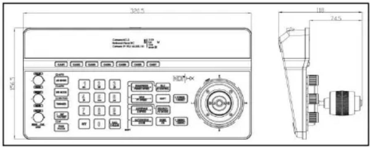
4. Menu Setting
3.4 Interface Description:
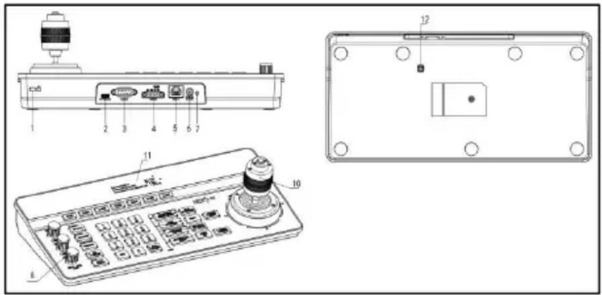
- Lock hole
- Network interface
- Button
- Upgrade interface
- Power interface
- Joystick
- RS232 interface
- Indicator light
- Display screen
- RS485 interface
- Adjusting knob
- Dial switch
3.5 Display Screen Content:
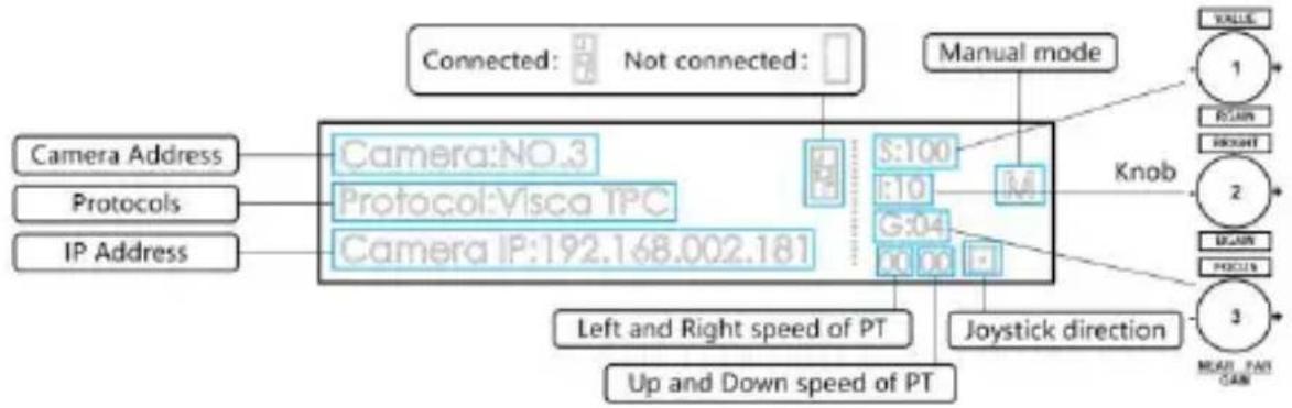
flowchart
graph LR
    A["Camera Address"] --> B["Camera:NO.3"]
    C["Protocols"] --> D["Protocol:Visca TPC"]
    E["IP Address"] --> F["Camera IP:192.168.002.181"]
    B --> G["S:100"]
    D --> H["S:10"]
    F --> I["G:04"]
    G --> J["M"]
    H --> J
    I --> J
    J --> K["Manual mode"]
    K --> L["Knob"]
    L --> M["JOYSTICK direction"]
    M --> N["Up and Down speed of PT"]
    N --> O["Left and Right speed of PT"]
    O --> P["UP and Down speed of PT"]
    P --> Q["UP and Down speed of PT"]
    Q --> R["UP and Down speed of PT"]
    R --> S["UP and Down speed of PT"]
    S --> T["UP and Down speed of PT"]
    T --> U["UP and Down speed of PT"]
    U --> V["UP and Down speed of PT"]
    V --> W["UP and Down speed of PT"]
    W --> X["UP and Down speed of PT"]
    X --> Y["UP and Down speed of PT"]
    Y --> Z["UP and Down speed of PT"]
    Z --> AA["UP and Down speed of PT"]
    AA --> AB["UP and Down speed of PT"]
    AB --> AC["UP and Down speed of PT"]
    AC --> AD["UP and Down speed of PT"]
    AD --> AE["UP and Down speed of PT"]
    AE --> AF["UP and Down speed of PT"]
    AF --> AG["UP and Down speed of PT"]
    AG --> AH["UP and Down speed of PT"]
    AH --> AI["UP and Down speed of PT"]
    AI --> AJ["UP and Down speed of PT"]
    AJ --> AK["UP and Down speed of PT"]
    AK --> AL["UP and Down speed of PT"]
    AL --> AM["UP and Down speed of PT"]
    AM --> AN["UP and Down speed of PT"]
    AN --> AO["UP and Down speed of PT"]
    AO --> AP["UP and Down speed of PT"]
    AP --> AQ["UP and Down speed of PT"]
    AQ --> AR["UP and Down speed of PT"]
    AR --> AS["UP and Down speed of PT"]
    AS --> AT["UP and Down speed of PT"]
    AT --> AU["UP and Down speed of PT"]
    AU --> AV["UP and Down speed of PT"]
    AV --> AW["UP and Down speed of PT"]
    AW --> AX["UP and Down speed of PT"]
    AX --> AY["UP and Down speed of PT"]
    AY --> AZ["UP and Down speed of PT"]
    AZ --> BA["UP and Down speed of PT"]
    BA --> BB["UP and Down speed of PT"]
    BB --> BC["UP and Down speed of PT"]
    BC --> BD["UP and Down speed of PT"]
    BD --> BE["UP and Down speed of PT"]
    BE --> BF["UP and Down speed of PT"]
    BF --> BG["UP and Down speed of PT"]
    BG --> BH["UP and Down speed of PT"]
    BH --> BI["UP and Down speed of PT"]
    BI --> BJ["UP and Down speed of PT"]
    BJ --> BK["UP and Down speed of PT"]
    BK --> BL["UP and Down speed of PT"]
    BL --> BM["UP and Down speed of PT"]
    BM --> BN["UP and Down speed of PT"]
    BN --> BO["UP and Down speed of PT"]
    BO --> BP["UP and Down speed of PT"]
    BP --> BQ["UP and Down speed of PT"]
    BQ --> BR["UP and Down speed of PT"]
    BR --> BS["UP and Down speed of PT"]
    BS --> BT["UP and Down speed of PT"]
    BT --> BU["UP and Down speed of PT"]
    BU --> BV["UP and Down speed of PT"]
    BV --> BW["UP and Down speed of PT"]
    BW --> BX["UP and Down speed of PT"]
    BX --> BY["UP and Down speed of PT"]
    BY --> BZ["UP and Down speed of PT"]
    BZ --> CA["UP and Down speed of PT"]
    CA --> CB["UP and Down speed of PT"]
    CB --> CC["UP and Down speed of PT"]
    CC --> CD["UP and Down speed of PT"]
    CD --> CE["UP and Down speed of PT"]
    CE --> CF["UP and Down speed of PT"]
    CF --> CG["UP and Down speed of PT"]
    CG --> CH["UP and Down speed of PT"]
    CH --> CI["UP and Down speed of PT"]
    CI --> CJ["UP and Down speed of PT"]
    CJ --> CK["UP and Down speed of PT"]
    CK --> CL["UP and Down speed of PT"]
    CL --> CM["UP and Down speed of PT"]
    CM --> CN["UP and Down speed of PT"]
    CN --> CO["UP and Down speed of PT"]
    CO --> CP["UP and Down speed of PT"]
    CP --> CQ["UP and Down speed of PT"]
    CQ --> CR["UP and Down speed of PT"]
    CR --> CS["UP and Down speed of PT"]
    CS --> CT["UP and Down speed of PT"]
    CT --> CU["UP and Down speed of PT"]
    CU --> CV["UP and Down speed of PT"]
    CV --> CW["UP and Down speed of PT"]
    CW --> CX["UP and Down speed of PT"]
    CX --> CY["UP and Down speed of PT"]
    CY --> CZ["UP and Down speed of PT"]
    CZ --> DA["UP and Down speed of PT"]
    DA --> DB["UP and Down speed of PT"]
    DB --> DC["UP and Down speed of PT"]
    DC --> DD["UP and Down speed of PT"]
    DD --> DE["UP and Down speed of PT"]
    DE --> DF["UP and Down speed of PT"]
    DF --> DG["UP and Down speed of PT"]
    DG --> DH["UP and Down speed of PT"]
    DH --> DI["UP and Down speed of PT"]
    DI --> DJ["UP and Down speed of PT"]
    DJ --> DK["UP and Down speed of PT"]
4. Menu Setting
3.6 Button Function
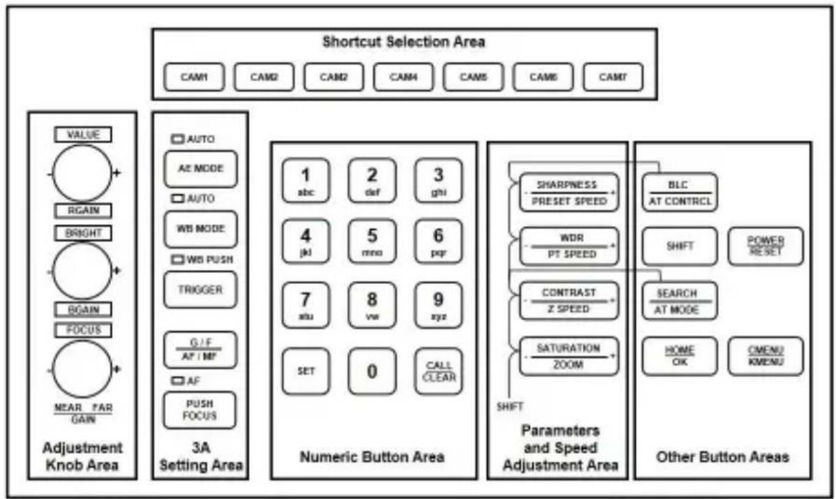
flowchart
graph TD
    A["Shortcut Selection Area"] --> B["VALU"]
    A --> C["AUTO"]
    A --> D["MODI"]
    A --> E["WBI MODE"]
    A --> F["WBI PUSH"]
    A --> G["TRIGGER"]
    A --> H["G/F AF / MF"]
    A --> I["AF PUSH FOCUS"]
    A --> J["Adjustment Knob Area"]
    K["Numeric Button Area"] --> L["1 abc"]
    K --> M["2 def"]
    K --> N["3 ghi"]
    K --> O["4 jkl"]
    K --> P["5 mno"]
    K --> Q["6 pcp"]
    K --> R["7 xu"]
    K --> S["8 vw"]
    K --> T["9 xyz"]
    K --> U["SET"]
    K --> V["0"]
    K --> W["CALL CLEAR"]
    X["Parameters and Speed Adjustment Area"] --> Y["SHARPNESS PRESET SPEED"]
    X --> Z["WDR PT SPEED"]
    X --> AA["CONTRAST Z SPEED"]
    X --> AB["SATURATION ZOOM"]
    X --> AC["SHIFT"]
    AD["Other Button Areas"] --> AE["BLC AT CONTRCL"]
    AD --> AF["SHIFT"]
    AD --> AG["POWER RESET"]
    AD --> AH["SEARCH AT MODE"]
    AD --> AI["HOME OK"]
    AD --> AJ["CMENU KMENU"]
3.6.1 Shortcut Selection Area
【CAM1】\~【CAM7】 Select the corresponding camera.
Note: Camera IP address can be quickly switched. In IP control mode, directly enter the last set of digits of the camera IP address on the keyboard, and then press CAM1\~CAM7 keys, you can quickly switch the current number of camera IP address to the number IP entered, so that you can support 1\~254 camera IP address fast switching.
【0\~9】+【CAM1】\~【CAM7】 Enter the camera IP address (last three digits), and then select one of the CAM1\~CAM7 keys to quickly connect to this camera.
3.6.2 Adjustment Knob Area, 3A Setting Area
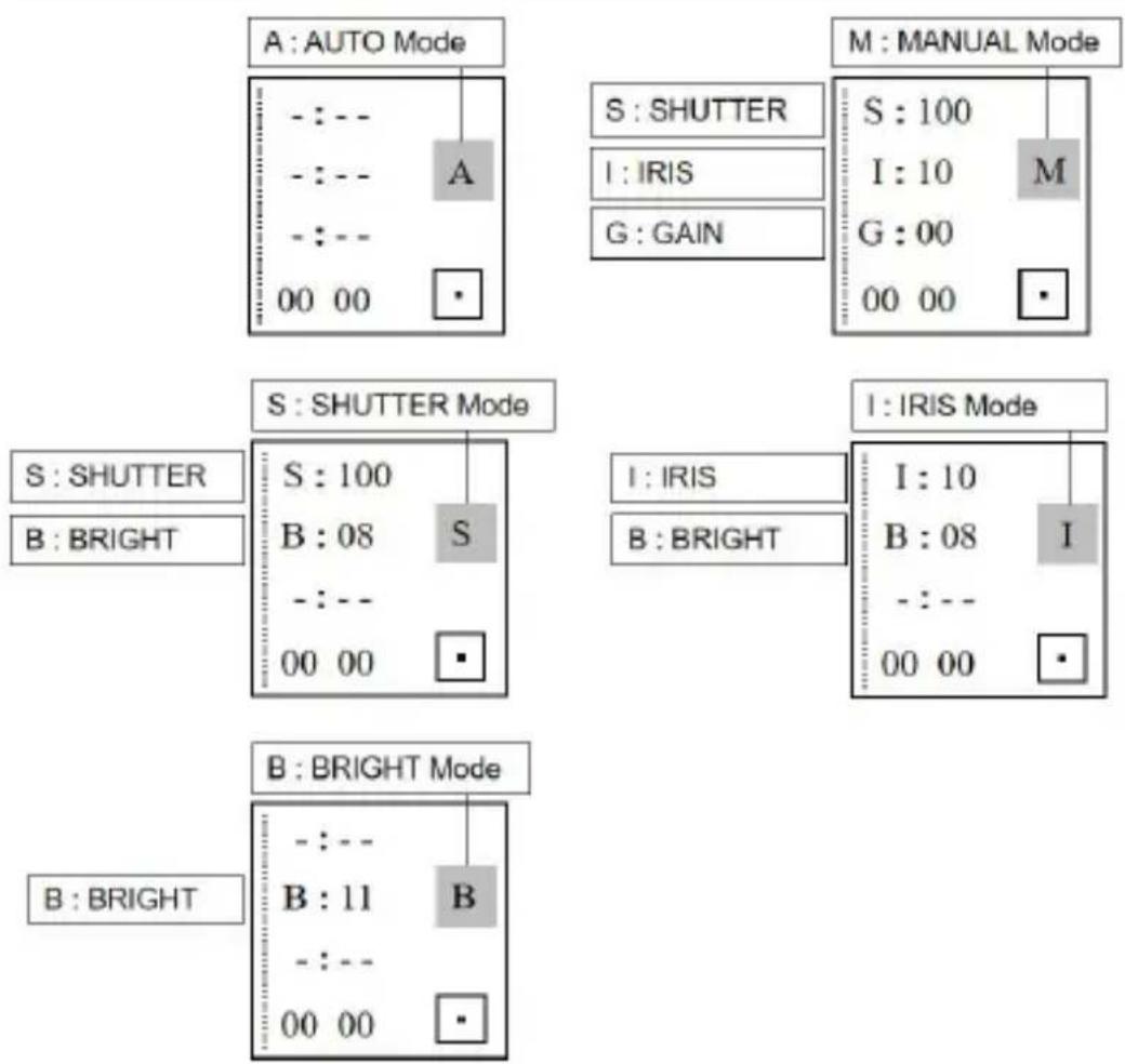
【AE MODE】 There is the word "AUTO" next to the button AE MODE. When the "AUTO"
light is on, automatic exposure mode is triggered; when the "AUTO" light is OFF, the other mode manual exposure, shutter priority, iris priority, bright priority can be selected, and at this time, the three knobs on the left side of the keyboard can adjust the shutter, iris, gain, bright and other parameters.
4. Menu Setting
flowchart
graph TD
    subgraph AUTO_Mode_A
        A1["---:---"] --> A2["A"]
        A3["---:---"] --> A4["00 00"]
    end
    subgraph MANUAL_Mode_M
        M1["S: 100"] --> M2["I: 10"] --> M3["G: 00"]
        M4["00 00"] --> M5["•"]
    end
    subgraph SHUTTER_MODE_S
        S1["S: 100"] --> S2["B: 08"] --> S3["00 00"]
    end
    subgraph SHUTTER_MODE_I
        I1["I: IRIS"] --> I2["B: BRIGHT"]
    end
    subgraph MANUAL_MODE_I
        I3["I: IRIS"] --> I4["B: 08"] --> I5["00 00"]
    end
    subgraph SHUTTER_MODE_B
        B1["B: BRIGHT"] --> B2["B: 11"] --> B3["00 00"]
    end
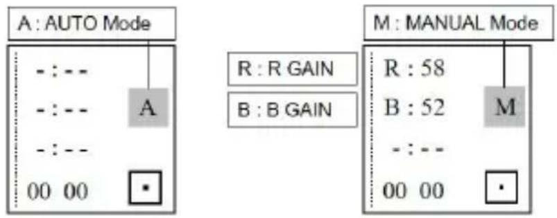
【WB MODE】 There is the word "AUTO" next to the button WB MODE. when the "AUTO"
light is on, it is AUTO and ATW mode; when the "AUTO" light is off, the manual, indoor and Sodium lamps, fluorescent lamps mode can be selected, then the camera red gain and blue gain ca adjusted through the first two knobs on the left side of the keyboard.
flowchart
graph TD
    A["A: AUTO Mode"] --> B["---"]
    B --> C["00 00"]
    D["R: R GAIN"] --> E["---"]
    E --> F["00 00"]
    G["B: B GAIN"] --> H["---"]
    H --> I["00 00"]
    J["M: MANUAL Mode"] --> K["---"]
    K --> L["00 00"]
    M["R: 58"] --> N["---"]
    N --> O["00 00"]
    P["M: MANUAL Mode"] --> Q["---"]
    Q --> R["00 00"]
    S["A"] --> T["---"]
    T --> U["00 00"]
    V["A"] --> W["---"]
    W --> X["00 00"]
【TRIGGER】 In Onepush mode ("WB PUSH" light is on), the automatic white balance is triggered once.
4. Menu Setting
【G/F / AF/M】F The word "AF" is next to the key G/F / AF/MF. When the "AF" light is on the automatic focus mode; when the "AF" light is not on, it is the manual focus mode, which can be adjusted by the third knob on the left side of the keyboard.
Short press [G/F / AF/MF] Switch the control gain and control focus mode. When in focus mode, the "FOCUS" light above the third knob on the left will be on.
Long press【G/F / AF/MF】 Switch between auto focus mode and manual focus mode.
【PUSH FOCUS】 Triggers autofocus once.
3.6.3 Numeric Button Area
【0\~9】+【SET】 Set the presets.
【0\~9】+ Short press 【CALL/CLEAR】 Call the presets.
【0\~9】+ Long press 【CALL/CLEAR】 Clear the Presets.
Note: Up to 128 presets can be set and recalled.
3.6.4 Parameters and Speed Adjustment Area
【-SHARPNESS + / - PRESET SPEED+】 Adjust the sharpness. / Adjust the preset speed.
【-WDR+/-PT SPEED+】 Adjust the WDR. / Adjust the camera PT speed.
【-CONTRAST+/-Z SPEED+】 Adjust the contrast. / Adjust the camera zoom speed.
【-SATURATION+/-ZOOM+】 Adjust the saturation. / Adjust the camera lens zoom.
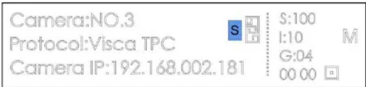
Note: Press the SHIFT button to switch between parameter setting mode and speed setting mod and the display will show "S".
When "S" is shown on the display, these 4 buttons can be used for parameter setting.
When the display does not show "S", these 4 keys can be used for speed setting and zoom.
3.6.5 Other Button Areas
【BLC / AT CONTRDL Backlight compensation switch, Auto-tracking switch. (Press the
4. Menu Setting
SHIFT button to switch.)
【SHIFT】 Switch between parameter adjustment mode and speed adjustment mode.
【SEARCH / AT MODE】 Search for IP address, Auto-tracking mode toggle in the menu. (Press the SHIFT button to switch.)
【HOME/OK】 Return to the original position of the camera.
【POWER/RESET】 Short press to control the camera power, long press to reset the camera.
【CMENU/KMENU】 Short press to open the camera menu, long press to open the keyboard menu.
3.6.6 Joystick Control
【Up】【Down】【Left】【Right】 Offset the joystick to control the camera to 4 directions.
【Zoom+】 Turn the joystick clockwise to zoom in.
【Zoom—】Turn the joystick counterclockwise to zoom out.
【Lock】 When controlling the camera, press the "lock" button, the camera keeps rotating in the previous control direction until the set lock time is exceeded or the camera rotates to the limit position.
4. Menu Setting
4.1 Operating Instructions:
- Long press CMENU/KMENU to open the keyboard menu; Adjust the joystick Up and Down to view the menu options; Right to enter the next option; Left to 1 to the previous option, short press CMENU/KMENU can also return to the previous option; numeric keys 0\~9 can set the corresponding parameters in some options.
- In the keyboard menu, you need to set the corresponding protocol, address in order to control the camera properly.
4.2 Menu options:
| System setting | Language | Chinese/English |
| Brightness | 1~15 | |
| BackLight | AUTO/ON/OFF | |
| Screen Prt | 10s~180s | |
| DHCP | OFF/ON | |
| Locol IP | 192.168.001.180 (Can be set) | |
| Mask | 255.255.255.000 | |
| Gateway | 192.168.001.001 | |
| Run Link | OFF/ON | |
| Reset | NO/YES |
| Camera setting | Camera | The keyboard can be set with 7 addresses: CAM1~CAM |
| Protocol | VISCA Serial, Pelco-P, Pelco-D, VISCA over IP, VISCA VISCA UDP, ONVIF, NDI(optional) | |
| IP Addr / Addres | Set the camera IP address or camera address. | |
| Port / Baundrate | Set the port or baud rate.Default port numbers for each IP protocol:ONVIF: 8000, NDI: 5961, VISCA: 52381 | |
| Username | Username setting, default: admin | |
| Password | Password setting, default: admin |
| PTZ setting | Pan Reverse | The left and right direction of the keyboard control can be |
4. Menu Setting
| Tilt Reverse | The up and down direction of the keyboard control can be | |
| Preset PT Spd | Set preset PT speed: 5~24 | |
| Preset Z Spd | Set preset Zoom speed: 1~7 | |
| Foucs Speed | Set focus sensitivity: 0~7 | |
| Lock Time | Set of lock time: 2~20(s) |
| Password setting | New PSD | Set a new password to access the keyboard menu |
| Confirm | Reconfirm the new password to access the keyboard | |
| Enable | Password switch to access the keyboard menu | |
| Version | Keyboard program version number and update date |
5. Wiring diagram
5.1 Connection in network mode:
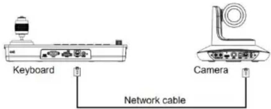
5.1.1 The keyboard is on the same LAN as the camera: The keyboard connects to the switch through the network cable, and the camera connects to the switch through the network cable. In the same LAN, set the same network segment, and set the corresponding protocol, IP address and port number, you can control the camera through the keyboard.
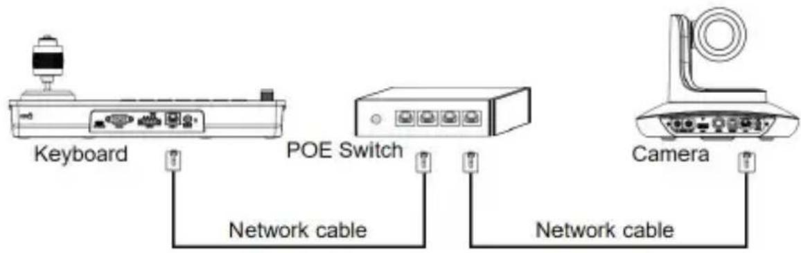
5.1.2 The keyboard is directly connected to the camera: The keyboard is connected to the camera through the network cable, set the same network segment, and set the corresponding protocol, IP address and port number, you can control the camera through the keyboard.
5. Wiring diagram
5.2 Connection in RS232 mode:
The keyboard connects to the camera via RS232 cable, set the corresponding protocol, address and baud rate, and you can control the camera via the keyboard.
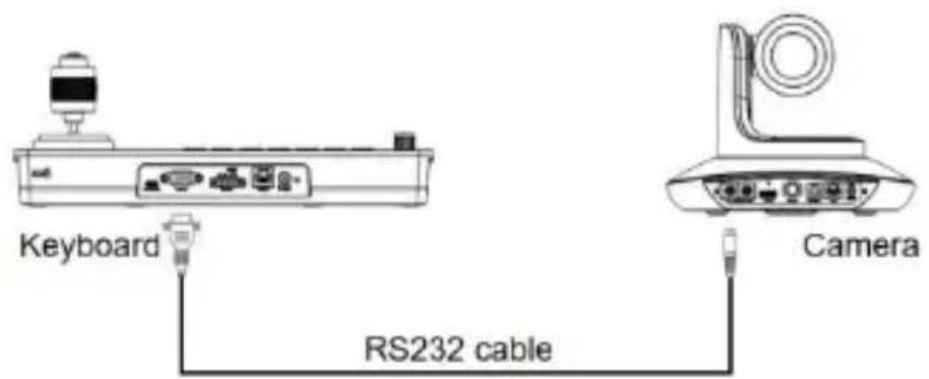
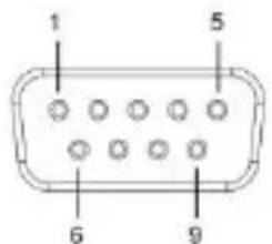
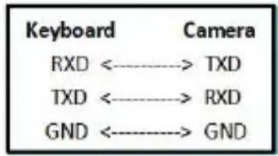
Line Sequence: Using the RS232 connection, pin 1 RXD of the keypad is
connected to the camera input interface TXD, pin 2 TXD of the keypad is connected to the camera RXD and pin 3 of the keypad is connected to the camera GND. (I also possible to use the standard RS232 interface of the control keypad to connect the camera.
flowchart
graph LR
    A["Keyboard"] --> B["Camera"]
    C["RXD"] <----> D["TXD"]
    E["TXD"] <----> F["RXD"]
    G["GND"] <----> H["GND"]
| DB9 Male (Pin type) | Pin Number | 2 | 3 | 5 | 1,4,6 | 7,8 |
| Signal Definition | RXD | TXD | GND | Internal connection | Internal connection |
5. Wiring diagram
5.3 Connection in RS422 mode:
The keyboard connects to the camera via RS422 cable, set the corresponding protocol, address and baud rate, and you can control the camera via the keyboard.
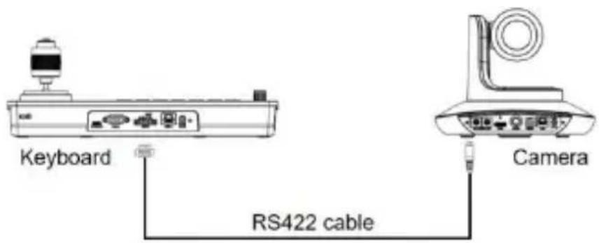
Line Sequence: Using the RS422 bus connection, the keyboard pin 1 TXD + connects to the camera's RXD-, the keyboard pin 2 TXD - connects to the camera's RXD +, the keyboard pin 3 RXD + connects to the camera's TXD -, the keyboard 4 RXD - connects to the camera's TXD+.
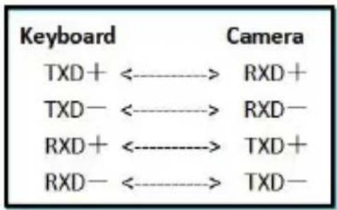
Note: Some cameras do not support RS422 control.
5.4 Connection in RS485 mode:
The keyboard connects to the camera via RS485 cable, set the corresponding protocol, address and baud rate, and you can control the camera via the keyboard.
5. Wiring diagram
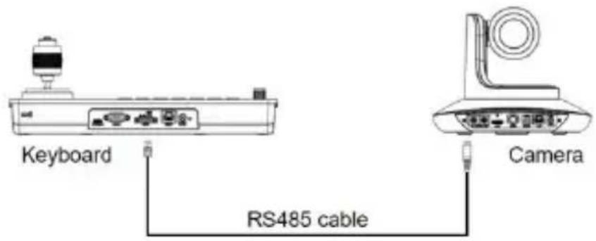
Line Sequence: Using the RS485 bus connection, the keyboard pin 1 TXD + connected to the camera RXD-, the keyboard pin 2 TXD- connected to the camera RXD +.
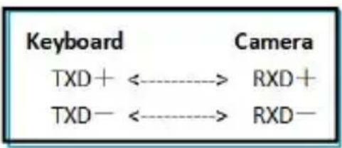
flowchart
graph LR
    A["Keyboard"] --> B["TXD+"]
    B --> C["RXD+"]
    D["TXD-"] --> E["RXD-"]
5.5 Cascade in RS232, RS422, RS485 mode:
The keyboard connects the RS232-IN port of camera No. 1 through RS232, RS422, RS485 lines, and then connects the RS232-IN port of camera No. 2 through the RS232-OUT port of camera No. 1 with a cascade line, and finally sets the corresponding protocol, address and baud rate on the keyboard to control camera No. 1 or camera No. 2 through the keyboard.
5. Wiring diagram
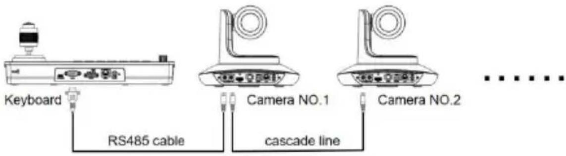
Line Sequence: Using RS232 cascade connection, the output of the keyboard is connected to the input of camera No. 1, the output of camera No. 1 is connected input of camera No. 2, and so on.
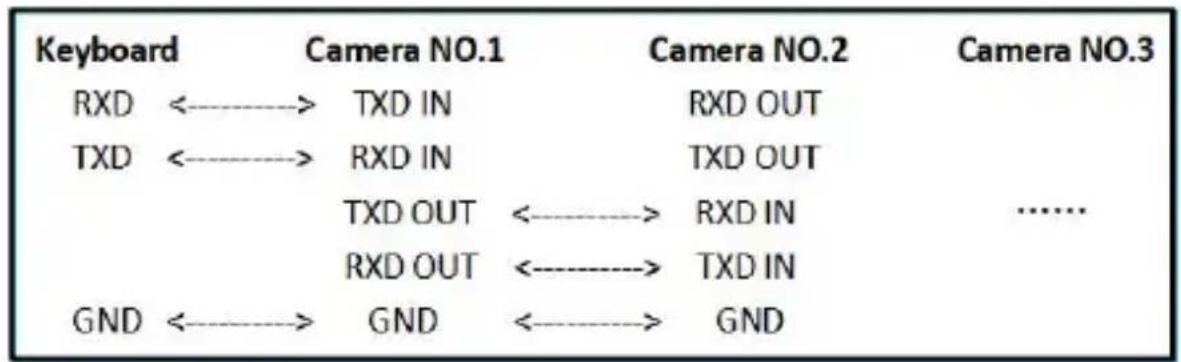
The connection method using RS422 and RS485 cascade is roughly the same as that of RS232.
6. WEB Configuration
6.1 Login WEB
The keyboard and computer connected to the same LAN, open to browser, enter the IP address (default address is 192.168.1.180), enter the interface, you can choose the language (Chinese or English), enter the user and password to login, as shown or right.
Keyboard Control
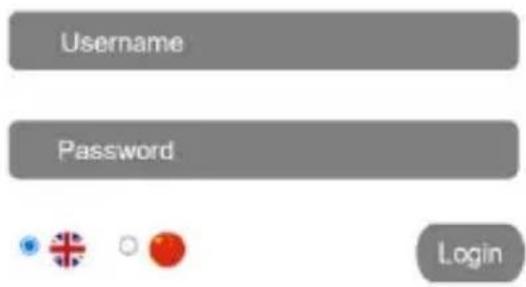
(Default username: admin Default password: admin)
After successful login, you will be taken directly to the system configuration screen as shown below.
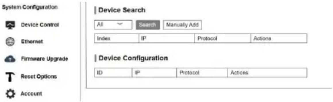
6.2 Device Control
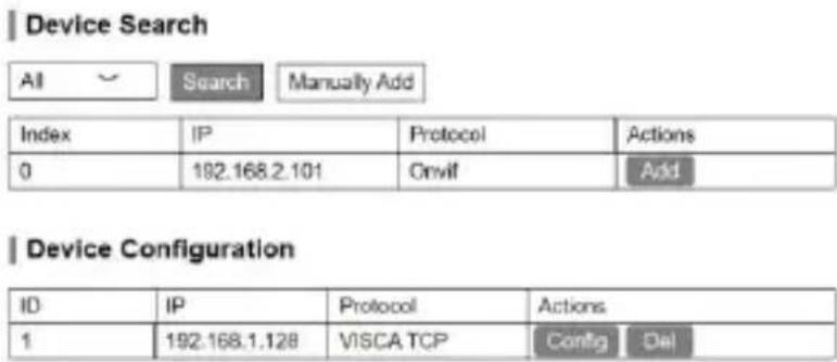
6.2.1 Device Search
Search for IP addresses and protocols of cameras on the same LAN and add to the keyboard configuration; you can also add camera IP addresses and protocols manually.
6.2.2 Device Configuration
Modify and delete the IP address, protocol and port number of the already configured camera.
6. WEB Configuration
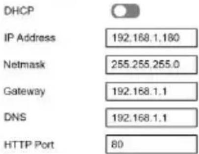
6.3 Ethernet Parameter
Set the network parameters of keyboard, including DHCP switch, Address, Netmask, Gateway, DNS, HTTP Port.
Ethernet
Save
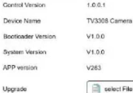
6.4 Firmware Upgrade
Check the keyboard device name and version information, and also, you can use files to upgrade the keyboard system. Please not power off during the upgrade process.
| Firmware Upgrade
6.5 Reset Options
Perform a complete reset or reboo the keyboard.
Reset/Reboot: Resets all parameters reboots the device.
| Reset Options
ResetReboot
Reset all camera setting to their default values and reboot
Robost
Reboot: Reboot the device.
6. WEB Configuration
6.6 Account
Set the login and password of keyboard.
First enter the Account number needs to be set, then enter the pa that needs to be set twice (Passwc Confirm Password), and then click "Save".
| Account Settings
Account
Password
Confirm Password
Save
After setting the account number and password, please remember the account number and password, otherwise you will not be able to log in the WEB side inte
7. Frequently Asked Questions
| Frequently Asked Questions | |
| Adverse Description | Solution Ideas |
| The keyboard cannot control the camera in network mo | Check if the network cable is connected properly. |
| Check whether the camera supports the set protocol. | |
| Check if the keyboard screen shows connected. The display indicates a successful connection. | |
| Check whether the IP address, protocol and port number set keyboard are consistent with those of the camera. | |
| Check if the keyboard and the camera are on the same LA | |
| Check whether the keyboard's local IP address and the cam address are in the same network segment. | |
| The keyboard cannot control the camera in RS232, RS422, RS485 mode. | Check whether the RS232, RS422, RS485 cables are good a whether the interface is loose. |
| Check whether T+, T-, R+, R- of RS422 are connected wr check whether T+, T- of RS485 are connected backwards. | |
| Check that the address, protocol and baud rate set on the are consistent with those of the camera. | |
| Some cameras can be controlled, some cameras cannot be controlled. | Check if the wiring of each part is normal. |
| Check that the parameters of each address code of the key consistent with those of the respective camera. | |
| When controlled with the keyboard, multiple cameras are controlled together. | Check that the protocols and addresses of the cameras being controlled together are consistent. |

Telecam Technology Co., Ltd
Add.: 6F, Building A, Shuanghuan Information Technology Industrial Park, No.8, Baoqing Rd, Longgang District, Shenzhen, 518116, China Tel: +86-755-33275155
Https://www.telycam.com
- IP&Serial Joystick Remote Control Keyboard
- Security Guidance....2
- Check Before Using....3
- Keyboard Description....4
- Menu Setting....11
- Wiring diagram....13
- WEB Configuration....18
- Frequently Asked Questions....21
- Cautions:
- Notice:
- Check Before Using
- Packing List
- The Wiring
- Bottom Dialing Switch
- Functional Features:
- Menu Setting
- Interface Description:
- Display Screen Content:
- Button Function
- Shortcut Selection Area
- Adjustment Knob Area, 3A Setting Area
- Numeric Button Area
- Parameters and Speed Adjustment Area
- Other Button Areas
- Joystick Control
- Operating Instructions:
- Menu options:
- Wiring diagram
- Connection in network mode:
- Connection in RS232 mode:
- Connection in RS422 mode:
- Connection in RS485 mode:
- Cascade in RS232, RS422, RS485 mode:
- WEB Configuration
- Login WEB
- Device Control
- Device Search
- Device Configuration
- Ethernet Parameter
- Ethernet
- Firmware Upgrade
- | Firmware Upgrade
- Reset Options
- | Reset Options
- Account
- | Account Settings
- Frequently Asked Questions
- Telecam Technology Co., Ltd
Brand : Telycam
Model : V-Joy+
Category : Uncategorized