
Greentherm T9800 SE 199 - Instant water heater and boiler BOSCH - Free user manual and instructions
Find the device manual for free Greentherm T9800 SE 199 BOSCH in PDF.
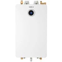


| Product Type | Tankless Water Heater |
| Model | Greentherm T9800 SE 199 |
| Brand | Bosch |
| Energy Source | Natural Gas or Propane |
| Power Input | 199,000 BTU/hr |
| Maximum Flow Rate (77°F inlet) | 14.2 GPM |
| Minimum Activation Flow | 0.45 GPM |
| Recirculation Capability | External pump required; pump control cable accessory available |
| Cascading | Up to 24 units with Intelligent Cascading Kit |
| Tank Loading Compatibility | Yes, with external pump and NTC sensor |
| Space Heating Integration | Combined DHW and space heating with air handler |
| Water Connections | 3/4" NPT (typical) |
| Gas Connection | 3/4" NPT (typical) |
| Dimensions (H x W x D) | 29.5" x 18.5" x 9.5" (approx.) |
| Weight | 60 lbs (approx.) |
| Safety Features | Pressure relief valve, check valves, condensate neutralizer compatible |
| Maintenance | Clean inlet water filter regularly; condensate neutralizer may require service |
| Installation Requirements | Must be installed by certified professional; follow local codes |
Frequently Asked Questions - Greentherm T9800 SE 199 BOSCH
User questions about Greentherm T9800 SE 199 BOSCH
0 question about this device. Answer the ones you know or ask your own.
Ask a new question about this device
Download the instructions for your Instant water heater and boiler in PDF format for free! Find your manual Greentherm T9800 SE 199 - BOSCH and take your electronic device back in hand. On this page are published all the documents necessary for the use of your device. Greentherm T9800 SE 199 by BOSCH.
USER MANUAL Greentherm T9800 SE 199 BOSCH
WARNING:
Follow each appliance's instructions precisely.
Installation and service must be performed by a trained and certified installer, service agency or the gas supplier.
Application drawings in this manual are conceptual only and do not purport to address all design, installation, code, or safety considerations.
The diagrams in this manual are for reference use by code officials, designers and licensed installers. It is expected that installers have adequate knowledge of national and local codes, as well as accepted industry practices, and are trained on equipment, procedures, and applications involved. Drawings are not to scale.
Refer to the appliance and accessory installation manuals for additional detailed information!
Greentherm T9800/9900 SE/SEO/SEi 160/199
RESIDENTIAL TANKLESS WATER HEATERS

BOSCH
Applications Manual
Table of Contents
1 Key to Symbols and Safety Instructions 4
1.1 Key to Symbols 4
1.2 Safety 4
2 Introduction 5
3 Water Heater Sizing 6
3.1 Sizing Tankless Water Heaters 6
4 Applications 8
4.1 Single Installation 8
4.2 Domestic Hot Water Recirculation 9
4.2.1 Recirculation system types 9 4.2.2 Recirculation with the Greentherm T9900 models 11 4.2.3 Recirculation with the Greentherm T9800 models 12
4.3 Tank Loading 13
4.3.1 Single tank loading installation 14 4.3.2 Single tank loading with recirculation installation 15 4.3.3 Multiple tank loading installation 16 4.3.4 Multiple T9800 tank loading with recirculation installation 17
4.4 Combined Domestic Hot Water and Space Heating with Air Handler 18
4.5 Multi-Unit Cascading 19
1 Key to Symbols and Safety Instructions
1.1 Key to Symbols
Warnings

Warnings in this document are identified by a warning triangle printed against a grey background.
Keywords at the start of a warning indicate the type and seriousness of the ensuing risk if measures to prevent the risk are not taken.
The following keywords are defined and can be used in this document:
▶ DANGER indicates a hazardous situation which, if not avoided, will result in death or serious injury. ▶ WARNING indicates a hazardous situation which, if not avoided, could result in death or serious injury. ▶ CAUTION indicates a hazardous situation which, if not avoided, could result in minor to moderate injury. ▶ NOTICE is used to address practices not related to personal injury.
Important information

The symbol indicates important information where there is no risk to people or property.
1.2 Safety
Please read safety precautions before installation

WARNING: READ INSTRUCTIONS
This Applications Manual is intended to present some of the most common applications of the Bosch Greentherm tankless water heaters, and must be used in combination with the appliance installation and operation manual. Failure to follow these instructions may result in improper installation, adjustment, service or maintenance and possibly resulting in fire, electrical shock, property damage, personal injury or death.
2 Introduction
This Applications Manual is intended to present some of the most common applications of the Bosch Greentherm tankless water heaters. Application drawings are shown with both piping and corresponding electrical schematics where applicable. Auxiliary equipment depicted does not necessarily represent a specific manufacturer or model number. There are a wide variety of techniques, practices and piping strategies possible when installing water heating appliances. It is the responsibility of the installing contractor to determine the best solution for the application.

WARNING: SAFETY RULES
All drawings are conceptual in nature and do not address all design, installation or safety considerations. Additional safety and/or auxiliary equipment may be needed. Drawings are for reference use by officials, designers and licensed installers. It is expected that installers have adequate knowledge of accepted industry practices for the equipment, procedures, and applications involved. It is the responsibility of the installer to ensure that the installation is in accordance with local building codes.
Although this manual covers many common applications for our products, system possibilities are virtually endless. Should you encounter an application that is not covered in this manual or have any questions regarding any of its content, we encourage you to contact your local sales representative or us directly at Bosch Thermotechnology Corp.
This manual is not a substitute for any of the appliance installation manuals. All specifications are subject to change.
3 Water Heater Sizing
This section describes guidelines on how to select the right tankless water heater size for a particular application. More detailed information is contained in the installation manuals. Download manuals at www.boschheatingandcooling.com.
3.1 Sizing Tankless Water Heaters
Rule of thumb sizing
Table 1 provides a general rule of thumb when sizing for most residential applications. For multi-unit applications or for a more detailed sizing method, use the Maximum Power Demand Calculation below in conjunction with the charts on the next page.
Maximum Power Demand Calculation
Step 1: Measure the maximum flow rate.
Measure the flow rates at each fixture that will be used simultaneously and add them together. If only one application will be used at a time, measure each fixture and use the maximum flow rate observed.
Possible measuring technique: using a known volume container, record the fill time. Perform the calculation below to determine the flow rate. For example, a 3.5 gallon fill time of 30 seconds is equivalent to 7 gallons per minute (GPM).
Flow rate (GPM) = Volume (gallons) / Fill time (sec) × 60 sec/min
Step 2: Calculate the desired temperature raise.
Identify the ground water temperature for the installation location, figure 1. Subtract this temperature from the desired hot water temperature to get the degree rise.
For example, if the desired hot water temperature is 110°F and the ground water temperature is 55°F, the desired degree rise is 55°F.
Step 3: Calculate maximum power required
Power (kBTU/hr) = Flow rate (GPM) × Temp Raise (°F) × 0.501
Step 4: Determine the models and number of appliances required to fulfill required power, by selecting a combination of appliances that meets or exceeds maximum required power.
Example 1: Maximum required power calculated in step 3 is 150kBTU/hr. Select one T9800/9900 160 model, since this model is able to supply up to 160kBTU/hr, which is more than the maximum required for the application.
Example 2: Maximum required power calculated in step 3 is 370kBTU/hr. Select two T9800/9900 199 models, since this model is able to supply up to 199kBTU/hr, so two units will be able to supply 398kBTU/hr, which is more than the maximum required for the application.

Figure 1 Average Ground Water Temperatures
| Model Power | Inlet temperature (°F) | |||||||||
| 77° 72° | 67° 62° | 57° 52° | 47° 42° | 37° | ||||||
| 9800/9900 SE/SEO/SEi | 199 kBTU/hr |  |  |  |  |  |  |  |  |  |
| 14.2 GPM | 12.1 GPM | 10.5 GPM | 9.3 GPM | 8.3GPM | 7.5 GPM | 6.9 GPM | 6.3 GPM | 5.9 GPM | ||
| 9800/9900 SE/SEO/SEi | 160 kBTU/hr | |||||||||
| 11.4 GPM | 9.6 GPM | 8.4 GPM | 7.4 GPM | 6.6 GPM | 6.0 GPM | 5.5 GPM | 5.0 GPM | 4.7 GPM | ||
Table 1 Maximum hot water flow for multiple inlet water temperatures.
Simultaneous shower use was rounded to the nearest whole number based on the following: Tankless set temperature of 120°F, shower temperature of 105°F, ground water temperature as shown in the table, and shower head flow rates of 2gpm.

Showerhead - 2 GPM
4 Applications
4.1 Single Installation
![graph TD A["Domestic Hot Water"] --> B["Condenser"] C["Domestic Cold Water"] --> B D["NBT-23 Condensate Neutralizer 1) (part# 7 738 005 514) --> E[To drain or pump"] E --> F["Valve"] G["Pressure relief valve"] --> H["Potable expansion tank 1)"] H --> I["Drip leg / Sediment trap"]](/content/2026/05/913442/images/b79243c38b037aaae39ac6196957062c13e506c4e74a31cd237171e98dad15c5.jpg)
Figure 2 1) as required by local code.
DISCLAIMER: This drawing is conceptual in nature, not to scale and for reference only. Additional functional, installation, and safety devices may be needed or required. All work pertaining to the installation shall be in full compliance with all legal requirements, including national and local codes. Best installation practices should be followed.
4.2 Domestic Hot Water Recirculation
Hot water recirculation is a technology that provides hot water virtually instantly at the point of use by circulating hot water through the home's domestic hot water pipes.
The benefits of hot water recirculation are the reduction in the amount of water wasted and wait time for hot water to arrive at the point of use.
The Greentherm 9000 models have been designed for hot water recirculation. All Greentherm 9000 models have the capability of controlling an externally powered pump by switching power ON and OFF.
The T9900 models have an integrated pump, which is controlled and powered by the tankless.
The Greentherm 9000 models offer multiple recirculation settings, such as recirculation scheduling, comfort levels, and on-demand recirculation via app. For information on how to change these settings, refer to the installation and operations manual.

The flow rate through the recirculation system must be larger than the activation flow rate of the water heater, 0.45 GPM.

For direct domestic hot water recirculation and tank loading applications:
Run the system for 30 minutes to remove debris from the plumbing. Then remove the unit's inlet water filter to decrease pressure drop through the system. If the inlet water filter, when removed, contains debris, it is recommended to install a 40 mesh Y-strainer (installer supplied) on the cold water inlet.

Domestic hot water recirculation will increase appliance operation time, and consequently increase maintenance requirements.
4.2.1 Recirculation system types
There are two basic types of recirculation systems.
▶ Dedicated return line making a complete hot water loop from the water heater to each water point of use and back to the water heater (Figure 3). ▶ Cross-over valve that connects the hot water line to the cold water line at the farthest fixture (Figure 4).
4.2.1.1 Recirculation system with dedicated return line
The preferred recirculation system uses a dedicated return line. See figure 3.
![graph TD A["1"] --> B["2"] B --> C["3"] C --> D["4"] D --> E["5"] E --> F["6"] F --> G["7"] G --> H["8"] H --> I["9"] I --> J["10"] style A fill:#f9f,stroke:#333 style B fill:#f9f,stroke:#333 style C fill:#f9f,stroke:#333 style D fill:#f9f,stroke:#333 style E fill:#f9f,stroke:#333 style F fill:#f9f,…](/content/2026/05/913442/images/5808f3fd494bb31c3ce9b06e4828e5a812790d099b724c6b9ebbadc37e8267ad.jpg)
Figure 3 Recirculation application with dedicated return line
[1] Cold water supply [2] Check valve, field supplied [3] Circulator pump, field supplied [4] Expansion tank, field supplied [5] Circulator cable accessory [6] Greentherm T9800 SE / SEC [7] PRV [8] Shutoff valves, field supplied
4.2.1.2 Recirculation system using a cross-over valve
Homes built without a dedicated return line can have a cross-over valve installed under the sink located farthest from the water heater allowing for recirculation as shown in Figure 4.
![graph TD A["Top Section"] --> B["Component 10"] A --> C["Component 11"] B --> D["Flow Path ③"] C --> E["Flow Path ④"] D --> F["Valve ②"] E --> G["Valve ⑤"] F --> H["Valve ①"] G --> I["Valve ②"] H --> J["Valve ③"] I --> K["Valve ④"] J --> L["Valve ⑤"] K --> M["Valve ⑥"] L --> N["Valve ⑦"] M --> O["Va…](/content/2026/05/913442/images/648a982209cc118b9c57a4f26fe985996bcb53a6efe01c5797137c1d31768ab1.jpg)
Figure 4 Recirculation application with cross-over valve. Double cross-over valve used to reduce system pressure drop, and ensure proper recirculation performance.
[1] Cold inlet supply [2] Check valve, field supplied [3] Expansion tank, field supplied [4] Shutoff valves, field supplied [5] Cold water inlet [6] Gas supply [7] Shutoff gas valve [8] Hot water outlet [9] Pressure relief valve [10] Grundfos cross-over valve (X2) [10] SS flexible hoses

Cross-over valves are not allowed in some states and localities. Verify with your local codes if cross-over valves are allowed.

The pressure drop through the cross-over valve can be very high, resulting in a flow rate below the minimum activation flow rate required by the water heater.
4.2.2 Recirculation with the Greentherm T9900 models
The T9900 models have an integrated pump which removes the need to use an external pump, and simplifies the installation.
It is recommended that the recirculation system is designed to allow a recirculation flow rate greater than 1 GPM. Refer to Figure 5 and Figure 6 for the hydraulic curve of the T9900 models' integrated pump and the tankless pressure drop curve for proper system dimensioning.
Recirculation internal pump![| Q [GPM] | H [ft] | | ------- | ------ | | 83210 | 2.5 |](/content/2026/05/913442/images/87571d15bd85e5c4f67e3c27117692f50a32e40c64d7799132602f97242cd3bd.jpg)
Figure 5 Hydraulic Curve
7 6
Pressure drop curve
Figure 6 Pressure drop curves for Greentherm 9000 models
4.2.3 Recirculation with the Greentherm T9800 models
Recirculation with the T9800 models requires the installation of an external pump.
The T9800 models have the capability of controlling an externally powered pump by switching power ON and OFF using the accessory pump cable kit 7736504585. See Figure 7.

Use only bronze or stainless steel pumps. Do not use pumps of iron construction as they will oxidize and pose health risks.
Refer to pump manufacturer's specifications to select a pump that will provide adequate flow through the recirculation system.
A flow rate through the recirculation system greater than 1 GPM is recommended.

The flow rate through the recirculation system must be larger than the activation flow rate of the water heater, 0.45 GPM.

Figure 7
4.3 Tank Loading
Tank loading pairs tankless water heaters with storage tanks to maximize peak flow for high demand applications. A tank load system, because of the added storage, can provide a high peak flow with fewer tankless units and lower installed cost.
Tank loading is recommended for high cycle applications such as commercial kitchens with hand sprayers.
These guidelines should be followed to maximize system output:
▶ Ensure flow through each water heater is between 3.5-5.0 gpm. Use an external pump to achieve the target flow rate. For best performance, plumb the system or configure the tank to draw cold supply water into the water heater during hot water use. Maintain a 15 degree temperature difference between tankless set-point and desired tank temperature. ▶ Do not use a cascading kit in a tank loading application. When multiple tankless water heaters are used, the total equivalent length of piping to each unit should be kept roughly equal. A reverse return piping scheme is recommended to equalize flow through each water heater.
Wiring Detail for Tank Loading Application
Figure 8
4.3.1 Single Tank Loading Installation
![graph TD A["Hot Water Supply"] --> B["Storage Tank"] B --> C["External NTC sensor (part# 7 736 504 583)"] C --> D["NBT-23 Condensate Neutralizer 1) (part# 7 738 005 514)"] D --> E["To drain or pump"] E --> F["Cold Water Supply"] B --> G["Local code requirements may require installation of a thermost…](/content/2026/05/913442/images/c9f06dae732538e93054d07b9605e001fbcfb881cc5d407a40a8519754195d12.jpg)
Legend
 | Full-port ball valve | [2ZD3] | Thermostatic mixing valve | [2Z7G] | Y-type strainer |
 | Union | [SCT5] | Check valve |  | Aquastat or Thermistor |
| [DOYO] | Potable expansion tank | [87DV] | Pressure relief valve |  | Circulator |
1) as required by local code.
DISCLAIMER: This drawing is conceptual in nature, not to scale and for reference only. Additional functional, installation, and safety devices may be needed or required. All work pertaining to the installation shall be in full compliance with all legal requirements, including national and local codes. Best installation practices should be followed.
4.3.2 Single tank loading with recirculation installation
![graph TD A["Hot Water Supply"] --> B["Storage Tank"] B --> C["External NTC sensor (part# 7 736 504 583)"] C --> D["Recirc Return"] D --> E["Cold Water Supply"] F["NBT-23 Condensate Neutralizer 1) (part# 7 738 005 514) --> G[Gas"] G --> H["see wiring detail Section 4.3, page 13"] H --> I["Local code…](/content/2026/05/913442/images/9ef21b3f3ad100918dc298fa794f93e53676b2c2eb315d760130ee07db56dc0b.jpg)
Legend
| [7706] | Full-port ball valve |  | Thermostatic mixing valve |  | Y-type strainer |
 | Union |  | Check valve | [STC8] | Aquastat or Thermistor |
| [DA2X] | Potable expansion tank |  | Pressure relief valve |  | Circulator |
1) as required by local code.
DISCLAIMER: This drawing is conceptual in nature, not to scale and for reference only. Additional functional, installation, and safety devices may be needed or required. All work pertaining to the installation shall be in full compliance with all legal requirements, including national and local codes. Best installation practices should be followed.
4.3.3 Multiple tank loading installation
![graph TD A["Hot Water Supply"] --> B["Storage Tank"] B --> C["Pump Relay"] C --> D["Cold Water Supply"] D --> E["NBT-23 Condensate Neutralizer 1"] E --> F["To drain or pump"] F --> G["Gas"] G --> H["Local code requirements may require installation of a thermostatic mixing valve in some installations…](/content/2026/05/913442/images/151585a11352fc9457f6a2e292fa6ec8498f4a231dd765fdebba0b8130b74fb6.jpg)
Legend
 | Full-port ball valve | [HTTO] | Thermostatic mixing valve | [ZYWO] | Y-type strainer |
 | Union | [OS78] | Check valve | [WEDW] | Aquastat |
| [TWSX] | Potable expansion tank |  | Pressure relief valve | 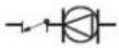 | Circulator |
1) as required by local code.
DISCLAIMER: This drawing is conceptual in nature, not to scale and for reference only. Additional functional, installation, and safety devices may be needed or required. All work pertaining to the installation shall be in full compliance with all legal requirements, including national and local codes. Best installation practices should be followed.
4.3.4 Multiple T9800 tank loading with recirculation installation
![graph TD A["Pump Relay"] --> B["Storage Tank"] B --> C["Hot Water Supply"] C --> D["Local code requirements may require installation of a thermostatic mixing valve in some installations."] D --> E["Recirc Return"] E --> F["Cold Water Supply"] F --> G["To drain or pump"] G --> H["NBT-23 Condensate Ne…](/content/2026/05/913442/images/e660b4b9dc0fd49dbd0b462aea3cce470a4cb051ca231749631c4707681e478e.jpg)
Legend
| [3X48] | Full-port ball valve | [228Y] | Thermostatic mixing valve |  | Y-type strainer |
 | Union |  | Check valve | [<366] | Aquastat |
 | Potable expansion tank | [HHWHT] | Pressure relief valve |  | Circulator |
1) as required by local code.
DISCLAIMER: This drawing is conceptual in nature, not to scale and for reference only. Additional functional, installation, and safety devices may be needed or required. All work pertaining to the installation shall be in full compliance with all legal requirements, including national and local codes. Best installation practices should be followed.
4.4 Combined Domestic Hot Water and Space Heating with Air Handler
Combined domestic hot water and space heating using air handler is possible with the Greentherm 9000 models.
![graph TD A["See table 9, page 19 for pairing Bosch Air Handlers with Bosch Cased Coils"] --> B["Hot Water Supply"] B --> C["Hot Water Return"] C --> D["Room Thermostat"] D --> E["Domestic Hot Water"] E --> F["Local code requirements may require installation of a thermostatic mixing valve in some ins…](/content/2026/05/913442/images/a459d6e0bd2e88030990c8c7603a59f9f2b433c76a405873b1aa77078ff65aff.jpg)
Legend
| [HETX] | Full-port ball valve | [2X40] | Thermostatic mixing valve |  | Automatic Air Separator |
| [STCC] | Union | [2W2W] | Check valve |  | Hose bib |
| [8C30] | Potable expansion tank | [6A2H] | Pressure relief valve | [ST42] | Circulator with flow check |
1) as required by local code.

Applications of combined domestic hot water and space heating in an open loop configuration, when combined with recirculation, are not recommended and desired performance is not guaranteed. These applications will require special configurations to ensure proper interaction between the different sub-systems (e.g. Air Handler, Mixing valve, etc.).
DISCLAIMER: This drawing is conceptual in nature, not to scale and for reference only. Additional functional, installation, and safety devices may be needed or required. All work pertaining to the installation shall be in full compliance with all legal requirements, including national and local codes. Best installation practices should be followed.
4.5 Multi-Unit Cascading
Cascading up to 24 appliances is possible with the Greentherm 9000 models, using the accessory Intelligent Cascading Kit 7709003962.
![graph TD A["Hot Water Supply"] --> B["Cold Water Supply"] B --> C["Gas"] C --> D["NBT-23 Condensate Neutralizer 1"] D --> E["Intelligent Cascading Kit (part# 7 709 003 962)"] D --> F["To drain or pump"] D --> G["End"] style A fill:#f9f,stroke:#333 style B fill:#ccf,stroke:#333 style C fill:#cfc,stro…](/content/2026/05/913442/images/45f62c268188ba7502727293681b5f6680356221da1c932070878cc39d9c2cd3.jpg)
Legend
| Full port ball valve | Pressure relief valve | ||
| Union | Check valve | ||
| Potable expansion tank | |||

Appliance controlled recirculation cannot be activated simultaneously with cascading. If cascading mode is activated and you activate recirculation, the cascading mode will turn off, and vice-versa.

Both direct return and reverse return piping are acceptable plumbing design options.
DISCLAIMER: This drawing is conceptual in nature, not to scale and for reference only. Additional functional, installation, and safety devices may be needed or required. All work pertaining to the installation shall be in full compliance with all legal requirements, including national and local codes. Best installation practices should be followed.
United States and Canada
Bosch Thermotechnology Corp.
65 Grove Street
Watertown, MA 02472
Tel: 866-642-3198
Fax: 603-965-7581

- WARNING
- GREENTHERM T9800/9900 SE/SEO/SEI
- RESIDENTIAL TANKLESS WATER HEATERS
- BOSCH
- TABLE OF CONTENTS
- KEY TO SYMBOLS AND SAFETY INSTRUCTIONS
- INTRODUCTION
- WATER HEATER SIZING
- APPLICATIONS
- KEY TO SYMBOLS
- WARNINGS
- IMPORTANT INFORMATION
- SAFETY
- PLEASE READ SAFETY PRECAUTIONS BEFORE INSTALLATION
- WARNING: READ INSTRUCTIONS
- WARNING: SAFETY RULES
- SIZING TANKLESS WATER HEATERS
- RULE OF THUMB SIZING
- MAXIMUM POWER DEMAND CALCULATION
- SINGLE INSTALLATION
- DOMESTIC HOT WATER RECIRCULATION
- RECIRCULATION SYSTEM TYPES
- RECIRCULATION SYSTEM WITH DEDICATED RETURN LINE
- RECIRCULATION SYSTEM USING A CROSS-OVER VALVE
- RECIRCULATION WITH THE GREENTHERM T9900 MODELS
- RECIRCULATION WITH THE GREENTHERM T9800 MODELS
- TANK LOADING
- SINGLE TANK LOADING INSTALLATION
- SINGLE TANK LOADING WITH RECIRCULATION INSTALLATION
- MULTIPLE TANK LOADING INSTALLATION
- MULTIPLE T9800 TANK LOADING WITH RECIRCULATION INSTALLATION
- COMBINED DOMESTIC HOT WATER AND SPACE HEATING WITH AIR HANDLER
- MULTI-UNIT CASCADING
Brand : BOSCH
Model : Greentherm T9800 SE 199
Category : Instant water heater and boiler