impression Laser - Printer GLP - Free user manual and instructions
Find the device manual for free impression Laser GLP in PDF.


| Product Type | Moving head laser projector |
| Brand | GLP (German Light Products) |
| Model | impression Laser |
| Dimensions (base) | Width: 340 mm, Length: 145 mm |
| Height (head vertical) | 370 mm |
| Weight (net) | 7.5 kg (17 lbs) |
| Power Supply | ~100-240 V AC, 50-60 Hz (auto sensing) |
| Power Consumption | 170 VA (W) |
| Fuse | Micro-fuse 5x20 mm, T2.5A |
| Laser Source | Diode laser |
| Laser Lifetime | 10,000 hours |
| Laser Class | Class 4 |
| Beam Angle | 40° horizontal / 40° vertical |
| Pan Movement | 660° (16-bit), min. 3.2 seconds |
| Tilt Movement | 300° (16-bit), min. 1.5 seconds |
| DMX Control | USITT DMX-512, 3-pole XLR, 20 channels (Full mode) |
| Control Modes | DMX, ILDA, PC software, Stand alone autostart |
| Max Ambient Temperature | 45°C (113°F) |
| Mounting Positions | Floor, hanging, sideways |
| Safety Distance | At least 1.5 m from flammable material |
| Cleaning | Exit window weekly, fan/air channel monthly; use soft lint-free cloth and glass cleaner |
| Warranty | Void if opened or modified |
Frequently Asked Questions - impression Laser GLP
User questions about impression Laser GLP
0 question about this device. Answer the ones you know or ask your own.
Ask a new question about this device
Download the instructions for your Printer in PDF format for free! Find your manual impression Laser - GLP and take your electronic device back in hand. On this page are published all the documents necessary for the use of your device. impression Laser by GLP.
USER MANUAL impression Laser GLP
from software version 1.00 (Instruction version 1.2)
impression Laser
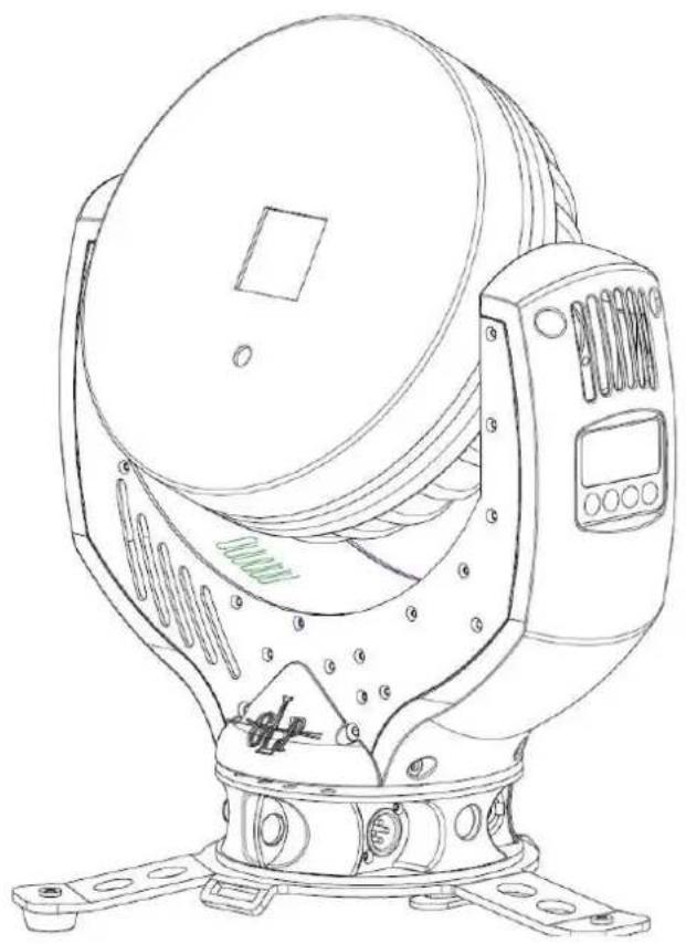
natural_image
Line drawing of a mechanical radar or surveying instrument with mounting base and control panel (no text or symbols)—GLP—
GERMAN LIGHT
PRODUCTS
e-mail: service@glp.de Internet: http://www.glp.de
Notes:
Table of content
1 Description of Device....4
1.1 Safety Instructions 5
2 Preparation and Installation 6
2.1 Mounting 6
2.1.1 Mounting on the floor (upright) 7
2.1.1 Mounting in hanging position (head down) 8
2.1.1 Mounting in a sideway position 8
2.2 Securing the Device 9
2.3 Connections 9
2.3.1 Power Supply....9
2.3.2 DMX 9
3 The Menu Field 10
4 DMX Channel Selection (DMX Protocol) 11
5 Maintaining and Cleaning the GLP iLaser 14
5.1 Safety regulations 14
5.2 Maintenance Intervals (rule-of-thumb) 14
6 Technical Specifications 15
7 Index....16
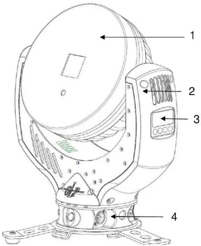
1 Description of Device
- Moving head (actively and passively cooled)
- Arm with various cooling vents
- LCD-Display/Menu (data entry)
- Base with various connectors and Camlock mounting system
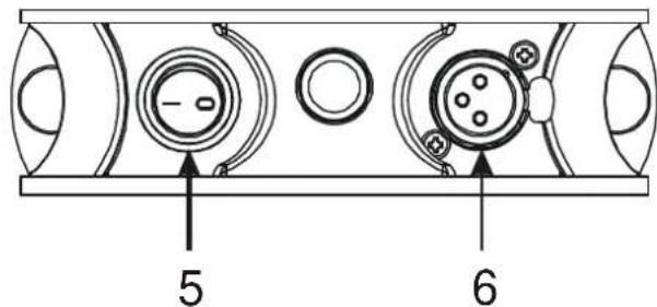
base side 1
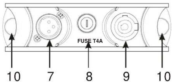
base side 2
- Power On/Off
- DMX- Output (3 pole)
- DMX- Input (3 pole)
- Micro-fuse 5x20mm, T2,5A
- Mains supply (Powercon)
- 2x Safety eyes
1.1 Safety Instructions

The GLP iLaser is an advanced technology product. To guarantee smooth operation, it is necessary to follow the following instructions.
The manufacturer of this device will not take responsibility of damages through any disregard of the information in this user manual. Warranty claims will also be cancelled in the event of the system casing being opened.
-
Make sure that before powering up the fixture, the fans and air inlets are clean and not blocked by anything.
-
Before powering up the fixture, ensure that the moving head part of the fixture can rotate unhindered through its full range of movement.
-
A safety distance of at least 1.5 m to any easily flammable material (e.g. decoration material) must be adhered to.
-
Attention! Don't touch the device during operation. Parts of the fixture can become hot and can cause injuries and / or damages.
-
The system doesn't contain any user serviceable parts. Opening the fixture will void the manufacturers warranty.
-
Danger of burning. Wait at least 15 minutes after disconnecting the AC power before changing the optical carrier on the fixture. Pay attention to possible hot parts of the system.
-
Never look directly into the Laser. Never use optical apertures with a distance less than 1.5 ~m to observe the beam of light. Laser Class 4. Not following these precautions can result in serious injury to your eyes and in particular, your retina.

Attention: Laser Class 4 can cause injuries of your eyes even without optical instruments in front of them or within a distance of less than 1.5m and short exposure time.
Avoid direct radiation to your eyes!
-
To allow a secure operation, follow also the Installation guide described in chapter 2. Operating the GLP iLaser without suitable safety aids like Safety cables or clamps/hooks can increase the risk of an accident.
-
Repair-, maintenance- and installation work shall be done by qualified or GLP iLaser certified staff only. You need to pay attention to the common rules of technology that are not explicit mentioned in this manual.
-
Use only original spare parts. Any structural modification on the system will terminate all warranty claims.
2 Preparation and Installation
2.1 Mounting
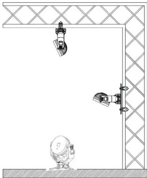
The GLP iLaser is fully operational whether it hangs or is mounted to a wall. It can also be operated while standing on the floor. Keep a safety distance of 0.5 m from any easily inflammable materials (decoration etc.).
natural_image
Technical line drawing of a mechanical assembly with a spherical component and two vertical components mounted on a grid-patterned frame (no text or symbols)
Pay attention to the regulations of: BGV C1 (former VBG 70), DIN VDE 0711-217 and EN 60825.
The installation shall be done by qualified personal only.
For the various mounting positions of the GLP iLaser (standing on the floor, sideways or hanging) different accessories kits are available. Using any required kits, along with the standard mounting connectors on the base of the fixture, will ensure a safe and firm installation.
2.1.1 Mounting on the floor (upright)
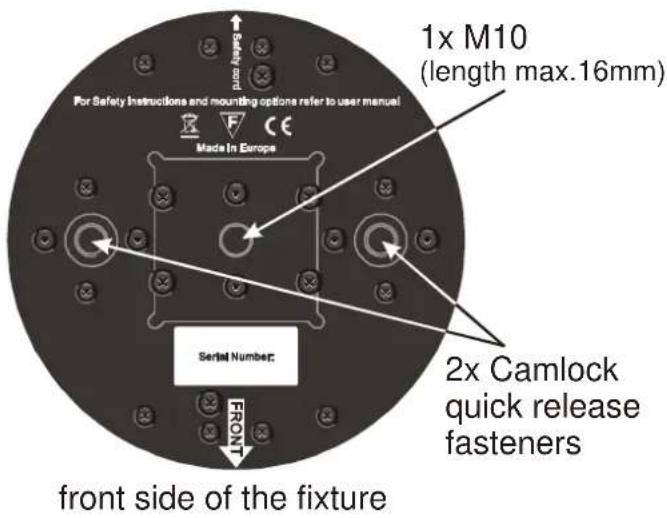
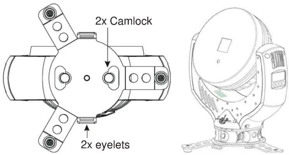
To operate the GLP iLaser in an upright position, please use the dedicated floor-stand which ships with all original fixtures. The floor stand is mounted to the base of the fixture using the two Camlock quarter turn fasteners. Line up and engage the camlock connectors from the floor stand into the base of the fixture and turn the two fasteners 90° to lock them. Do the opposite to release them again. On both sides you'll find eyelets to pull though a fixing strap. This allows additional bracing of the floor-stand during the upright operation.
2.1.1 Mounting in hanging position (head down)
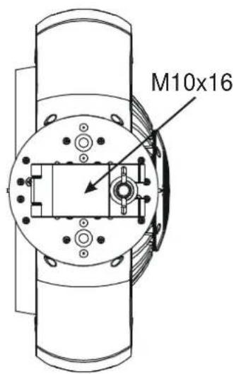
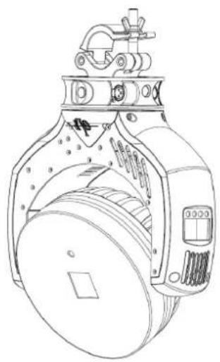
To operate the GLP iLaser in a hanging position, a half-coupler or similar clamp can be mounted directly to the bottom of the base using the M10x16 mm threaded socket.
natural_image
Technical line drawing of a mechanical device with no visible text or symbols2.1.1 Mounting in a sideway position
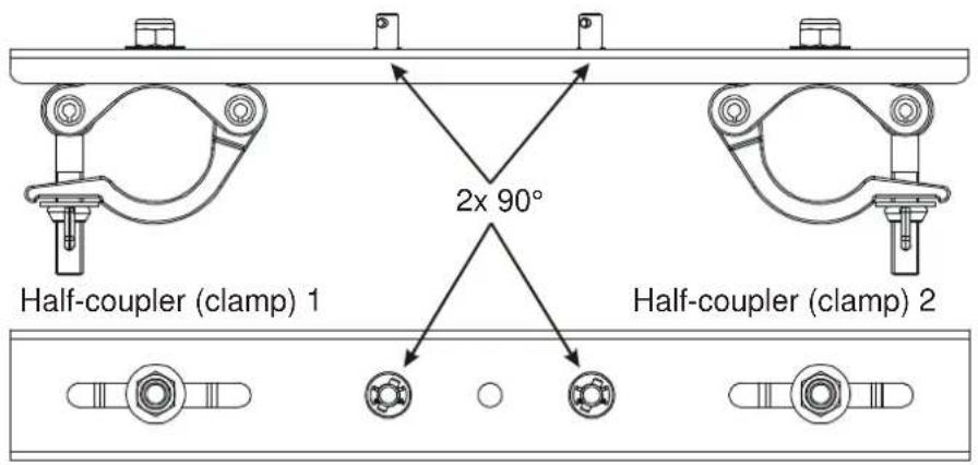
To operate the GLP iLaser in a sideways position, please use an additional mounting bar, available from GLP or one of their agents.. This mounting bar is fixed via the two camlock quick-release connectors. Two half-couplers or clamps are then used to hang the mounting bar. This technique is necessary to cope with the additional torque in this mounting position. Never use the "Mounting in hanging position" technique described above to secure the fixture in a sideway position, as the fixtures base can become damaged, and a secure installation cannot be assured.
2.2 Securing the Device
Regardless of the mounting method of the GLP iLaser you'll have to use a secondary safety wire. This safety wire can be attached to the fixture by threading it through one of the two holes provided on the base of the fixture. Ensure that the safety wire is securely fastened through the fixture and the fixtures mounting support. Install a safety wire that can hold at least 10 times the weight of the fixture.
2.3 Connections
2.3.1 Power Supply
\~90-240 Volt AC, 50-60 Hz, earth contact type plug - Powercon
Connected load 170VA (W) <=> 2,5 AT (micro-fuse 5x20mm)
Please see printing on the case for the right electronic supply!
Disconnect from the mains supply for changing the fuse and use only the above described micro-fuse type.
2.3.2 DMX
USITT DMX-512 Standard input/output in 3 pole connectors.
3 pole: Pin 1 = [Ground] / Pin 2 = [-] / Pin 3 = [+]
The DMX- Addressing starts at the DMX- Address [001].
3 The Menu Field
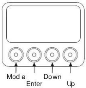
You'll find the control board on the side of the arm. It allows you to make all necessary adjustments of the GLP iLaser. With the Mode-key you get into the main menu. Afterwards you can navigate through the menu with the Up/Down-keys. Push the Enter-key to get to the next menu level or to confirm your settings. Select ON/OFF function settings with the Up/Down-keys. Confirm and save with the Enter-key (the display shows OK). Push the Mode-key to cancel the entry and go back to the main menu.
← MODE - ENTER →
| Level1 | Level 2 | Level 3 | Level 4 | Remark |
| DMX Start Address 001 | Define the DMX start address | |||
| Special Manual DMX | Manual control of all system functions | |||
| Pan | Manual control for Pan (X-movement) | |||
| Tilt | Manual control for Tilt (Y-movement) | |||
| Default Set | Display Contrast | Adjustment for the Display contrast | ||
| Resetting all functions to original values | ||||
| Impression Version | Reads out the current CPU software version | |||
| Adjust | Key code xxxx | Use the code for entering the calibration menu (for authorized persons only) | ||
| Pan Offset | Calibration for Pan-Offset | |||
| Tilt Offset | Calibration for Tilt-Offset | |||
| Diagnose | Clear EEPROM | Erase EEPROM memory | ||
| Diagnose functions | ||||
| Pos Feed Pan Delta | Internal data and function diagnose | |||
| Anz Ti0-Int-Err | Internal data and function diagnose | |||
| PFC Voltage | Show the present PFC voltage | |||
| Pos Feed Tilt Delta | Internal data and function diagnose | |||
| DMX Hold | Temperature Arm | Indicates the Reduces max | Indicates the arm temperature | |
| Temperature Head | ||||
| PAN/TILT Motor Power | Switches power for Pan/Tilt ON or OFF (disconnected from power) | |||
| PAN/TILT Silent Mode | ||||
| Defines whether the last DMX signal is stored or the lamp is switched OFF in case of signal interruption | ||||
| Position Feedback | Automatically position feedback (correction) for Pan/Tilt movement | |||
| Set DMX Image | Stores the Scene currently sent to the unit | ||
| DMX Input Monitor | Indicates the presently received DMX signal per DMX channel | ||
| Pan | Instantaneous value for Pan | ||
| Tilt | Instantaneous value for Tilt movement | ||
| Live time | Indicates the overall operation time of the system | ||
| Display | Adjust the display | ||
| Blackout | ON/OFF: Display OFF | ||
| Reverse Pan | Selects Inverse Pan, on or off | ||
| Reverse Tilt | Selects Inverse Tilt on or off | ||
| Reset | RESET all functions |
4 DMX Channel Selection (DMX Protocol)
Normal-Mode 20 DMX channels
We do not show Hexadecimal or Percentage values in here because the steps between each function are too small to be set properly.
| Channel Function | Should Default DMX | ||
| 1) Pan Coarse | 128 0..255 | ||
| 0 .. 660° | 0..255 | ||
| 2) Pan Fine | High- Pos ... High- Pos + 2,6° (16 Bit) | 0..255 | |
| 3) Tilt Coarse | 128 0..255 | ||
| 0 .. 300° | 0..255 | ||
| 4) Tilt Fine | High- Pos ... High- Pos + 1,2° (16 Bit) | ||
| 5) Access | 255 | ||
| Blackout | 0..31 | ||
| Basic Range | 35..95 | ||
| Standard Range | 97..159 | ||
| Extended Range | 161..223 | ||
| Full Range | 225..255 | ||
| 6) Folder | 0 | ||
| Page 1 | 0..15 | ||
| Page 2 | 17..31 | ||
| Page 3 | 33..47 | ||
| Page 4 | 49..63 | ||
| Page 5 | 65..79 | ||
| Page 6 | 81..95 | ||
| Page 7 | 97..111 | ||
| Page 8 | 113..127 | ||
| Page 9 | 129..255 | ||
| (7) File | 0 | ||
| Blackout | 0..32 | ||
| Cue 1 | 33..35 | ||
| Cue 2 | 37..39 | ||
| Cue 3 | 41..43 | ||
| Cue 4 | 45..47 | ||
| Channel Function Should Default DMX | |||
| Cue 5 49..51 | |||
| Cue 6 53..55 | |||
| Cue 7 57..59 | |||
| Cue 8 61..63 | |||
| Cue 9 65..67 | |||
| Cue 10 69..71 | |||
| Cue 11 73..75 | |||
| Cue 12 77..79 | |||
| Cue 13 81..83 | |||
| Cue 14 85..87 | |||
| Cue 15 89..91 | |||
| Cue 16 93..95 | |||
| Cue 17 97..99 | |||
| Cue 18 101..103 | |||
| Cue 19 105..107 | |||
| Cue 20 109..111 | |||
| Cue 21 113..115 | |||
| Cue 22 117..119 | |||
| Cue 23 121..123 | |||
| Cue 24 125..127 | |||
| Cue 25 129..131 | |||
| Cue 26 133..135 | |||
| Cue 27 137..139 | |||
| Cue 28 141..143 | |||
| Cue 29 145..147 | |||
| Cue 30 149..151 | |||
| Cue 31 153..155 | |||
| Cue 32 157..159 | |||
| Cue 33 161..163 | |||
| Cue 34 165..167 | |||
| Cue 35 169..171 | |||
| Cue 36 173..175 | |||
| Cue 37 177..179 | |||
| Cue 38 181..183 | |||
| Cue 39 185..187 | |||
| Cue 40 189..191 | |||
| Cue 41 193..195 | |||
| Cue 42 197..199 | |||
| Cue 43 201..203 | |||
| Cue 44 205..207 | |||
| Cue 45 209..211 | |||
| Cue 46 213..215 | |||
| Cue 47 217..219 | |||
| Cue 48 221..255 | |||
| (8) Playback Speed 128 | |||
| Normal Playspeed 0..15 | |||
| Pause 17..31 | |||
| 25 % Playback Speed to 99 % 33..127 | |||
| 100 % Playback Speed 128 | |||
| 101 % Playback Speed to 200 % | 129..255 | ||
| (9) Intensity 0 | |||
| 0 % to 100 % | 0..255 | ||
| (10) Z Position (Zoom) 128 | |||
| 0 % to 100 % | 0..255 | ||
| Channel Function | Should Default DMX | ||
| (11) X Size | 0 | ||
| 0 % to 100 % 0..255 | |||
| (12) Y Size | 0 | ||
| 0 % to 100 % 0..255 | |||
| (13) Rotation | 128 | ||
| 0° to 360° 0..255 | |||
| (14) X Position | 128 | ||
| Left to Right 0..255 | |||
| (15) Y Position | 128 | ||
| Down to Up 0.255 | |||
| (16) Visible Points | 255 | ||
| None to All | 0.255 | ||
| (17) Scan Rate | 255 | ||
| Default (30k) | 0..31 | ||
| 6k to 30k | 33..255 | ||
| (18) Release | 0 | ||
| Default | 0..31 | ||
| Hold | 33..95 | ||
| Loop | 97..159 | ||
| Next | 161..223 | ||
| Stop | 225..255 | ||
| (19) Color | 0 | ||
| No Colorization | 0..31 | ||
| Red | 33 | ||
| Orange | 44 | ||
| Yellow | 55 | ||
| Lime | 77 | ||
| Green | 88 | ||
| Cyan | 111 | ||
| Blue | 165 | ||
| Purple | 170 | ||
| Pink | 191 | ||
| Red | 221 | ||
| White | 230 | ||
| (20) Reserved | Reserved | ||
The access channel does de- or increase the overall channel-count of the fixture:
Basic Channel 1 to Channel 8
Standard Channel 1 to Channel 12
Extended Channel 1 to Channel 16
Full Channel 1 to Channel 20
Locking and unlocking the Control Panel
Please lock and unlock the control panel by pressing the menu keys MODE & ENTER & UP at the same time.
5 Maintaining and Cleaning the GLP iLaser
The GLP iLaser is a system of very low maintenance. It is only necessary to clean the air in- and outlets as well as the exit window from time to time. For a safe operation it is absolutely essential that the fixture is kept clean and that dust, dirt and smoke-fluid residues must not built up on or within the fixture. Otherwise the fixture's light-output will be significantly reduced or damages can occur. Regular cleaning will not only ensure the maximum light-output, but will also allow the fixture to operate reliably throughout its life.
A soft lint-free cloth moistened with any good glass cleaning fluid is recommended, under no circumstances should alcohol or solvents be used!
5.1 Safety regulations
- Pull out the main plug!
- Wait min. 15 minutes after the last operation to cool down the fixture.
5.2 Maintenance Intervals (rule-of-thumb)
The maintenance schedule of any given fixture depends on the installation environment. Hence no specific guidelines can be given. The cleaning intervals given below are suggestions, based on practical experience. We suggest that you start with these and develop your own maintenance schedule as you see the fixtures performance in your specific environment.
| Maintenance Task Interval How | ||
| Exit window weekly soft brush /lint-free cloth | ||
| Fan and air channel monthly | vacuum cleaner, airbrush, etc. | |
Attention:
- Never let optical parts come into contact with oil or fat.
- Before running the fixture wait until all parts are dried up.
6 Technical Specifications
| Power supply | |
| Power consumption | 170 VA (Watt) |
| Power Input | ~100-240 V AC, 50-60 Hz (auto sensing input) |
| Fuse protection | Micro-fuse 5x20 mm, T 2,5A |
| Operational Parameters | |
| Max. Ambient Temperature | 45°C / 113°F (integrated overheating switch) |
| Mounting Position | Any (see chapter mounting) |
| Laser - Additive Color mixing | |
| Laser | Diode |
| Lifetime | 10.000 h |
| Projector | |
| Horizontal beam angle 40° | |
| Vertical beam angle 40° | |
| SASRT (step response time) 0.3msec | |
| Controller | |
| DMX, ILDA, PC software, Stand alone autostart mode | |
| Resolution x and y - 16-bit | |
| Resolution RGB intensity - 8-bit | |
| DMX Control | |
| Standard USITT DMX-512, 3 pole XLR; [+] = Pin 3 [-] = Pin 2 [Ground] = Pin 1.Die DMX- Addressing starts at the DMX channel [001]. | |
| Pan / Tilt (8/16 Bit) | |
| Pan- movement 660° in min. 3,2 seconds (Position Feedback) | |
| Tilt- movement 300° in min. 1,5 seconds (Position Feedback) | |
| Weights and Measures | |
| Width of the base | 340 mm / 13.4 inches |
| Length of the base | 145 mm / 5.7 inches |
| height (head vertical) | 370 mm / 14.6 inches |
| Weight (net) | 7,5 kg / 17 lbs. |
7 Index
B
BGV C1....6
C
Circumference 14
Cleaning.... 14
D
Description of Device 4
DIN VDE 0711-217 6
DMX 9
DMX Protocol 11
E
e-mail 1
Enter-key 10
Eyelets 7
H
Half-couplers (clamps) 8
1
Instruction Version ...... 1
Internet....1
L
LED Class 2M 5
M
Maintenance 14
Menu Field 10
Micro-fuse 9
Mode-key....10
Mounting....6
Mounting in hanging Position 8
Mounting in sidewise Position 8
Mounting on the Floor 7
N
Normal-Mode 11
0
Optical parts 14
P
Pan-Movement 15
Power Supply 9
Powercon 4
s
Safety distance 6
Safety Instructions .... 5
Secure the Device 9
Software Version 1
T
Technical Specifications 15
Tilt- Movement 15
U
Up/Down-keys 10
v
VBG 70 6
W
Warranty claims 6
Weights and Measures 15

natural_image
Abstract black-and-white graphic with intertwined curved lines and a central circular shape (no text or symbols)
- impression Laser
- Table of content
- Description of Device....4
- Preparation and Installation 6
- Description of Device
- Safety Instructions
- Preparation and Installation
- Mounting
- Mounting on the floor (upright)
- Mounting in hanging position (head down)
- Mounting in a sideway position
- Securing the Device
- Connections
- Power Supply
- DMX
- The Menu Field
- DMX Channel Selection (DMX Protocol)
- Normal-Mode 20 DMX channels
- Locking and unlocking the Control Panel
- Maintaining and Cleaning the GLP iLaser
- Safety regulations
- Maintenance Intervals (rule-of-thumb)
- Attention:
- Index
- B
- C
- D
- E
- H
- 1
- L
- M
- N
- 0
- P
- s
- T
- U
- v
- W
Brand : GLP
Model : impression Laser
Category : Printer