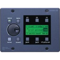
ICP1 - Panneau de contrôle électronique YAMAHA - Free user manual and instructions
Find the device manual for free ICP1 YAMAHA in PDF.


| Product Name | Yamaha ICP1 Intelligent Control Panel |
| Product Type | Intelligent Control Panel for DME series |
| Brand | Yamaha |
| Model | ICP1 |
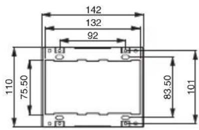
| Dimensions (Control Panel Unit) | 162 mm x 92 mm x 101 mm |
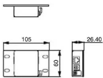
| Dimensions (Adaptor Box) | 105 mm x 60 mm x 26.4 mm |
| Net Weight | 1 kg |
| Power Supply | AC adaptor PA-300 (or equivalent) |
| Ethernet Interface | 100Base-TX/10Base-T, RJ45 connector |
| Operating Temperature Range | 10 to 35 °C |
| Storage Temperature Range | -20 to 60 °C |
| Maximum Cable Length | 100 meters total (Ethernet) |
| Recommended Cable Type | STP (Shielded Twisted Pair) Ethernet cable |
| Mounting Requirement | 3-gang wall box (US type), depth ≥ 44 mm |
| Package Contents | Control panel unit, ICP1 adaptor box, frame plate, AC adaptor (PA-300), owner's manual |
| Safety Compliance | FCC Part 15 Class B, EN55103-1/2 (E1, E2, E3, E4) for European models |
| Inrush Current (European models) | 70 A |
| Compatible Devices | DME64N/24N, DME Designer software |
| Cleaning Instructions | Use a soft dry cloth. Do not use solvents. |
| Repair and Service | No user-serviceable parts. Contact qualified Yamaha service personnel. |
Frequently Asked Questions - ICP1 YAMAHA
User questions about ICP1 YAMAHA
0 question about this device. Answer the ones you know or ask your own.
Ask a new question about this device
Download the instructions for your Panneau de contrôle électronique in PDF format for free! Find your manual ICP1 - YAMAHA and take your electronic device back in hand. On this page are published all the documents necessary for the use of your device. ICP1 by YAMAHA.
USER MANUAL ICP1 YAMAHA
Thank you for choosing the Yamaha ICP1 Intelligent Control Panel. Please refer to the DME64N/24N Owner's Manual or the DME Designer Owner's Manual for operational details.

Please read the "Precautions" section of this document thoroughly before installation.
For ICP1 installation refer to your Yamaha dealer, or the nearest Yamaha representative or authorized distributor listed in this document.
This product, when installed as indicated in the instructions contained in this manual, meets FCC requirements. Modifications not expressly approved by Yamaha may void your authority, granted by the FCC, to use the product.
-
IMPORTANT: When connecting this product to accessories and/or another product use only high quality shielded cables. Cable/s supplied with this product MUST be used. Follow all installation instructions. Failure to follow instructions could void your FCC authorization to use this product in the USA.
-
NOTE: This product has been tested and found to comply with the requirements listed in FCC Regulations, Part 15 for Class "B" digital devices. Compliance with these requirements provides a reasonable level of assurance that your use of this product in a residential environment will not result in harmful interference with other electronic devices. This equipment generates/uses radio frequencies and, if not installed and used according to the instructions found in the users manual, may cause interference harmful to the operation of other electronic devices. Compliance with FCC regulations does not guarantee that interference will not occur in all installations. If this product is found to be the source of interference, which can be determined by turning the unit "OFF" and "ON", please try to eliminate the problem by using one of the following measures:
Relocate either this product or the device that is being affected by the interference.
Utilize power outlets that are on different branch (circuit breaker or fuse) circuits or install AC line filter/s. In the case of radio or TV interference, relocate/reorient the antenna. If the antenna lead-in is 300 ohm ribbon lead, change the lead-in to co-axial type cable.
If these corrective measures do not produce satisfactory results, please contact the local retailer authorized to distribute this type of product. If you can not locate the appropriate retailer, please contact Yamaha Corporation of America, Electronic Service Division, 6600 Orangethorpe Ave, Buena Park, CA90620 The above statements apply ONLY to those products distributed by Yamaha Corporation of America or its subsidiaries.
* This applies only to products distributed by YAMAHA CORPORATION OF AMERICA.
(class B)
IMPORTANT NOTICE FOR THE UNITED KINGDOM Connecting the Plug and Cord
IMPORTANT. The wires in this mains lead are coloured in accordance with the following code:
BLUE : NEUTRAL
BROWN : LIVE
As the colours of the wires in the mains lead of this apparatus may not correspond with the coloured makings identifying the terminals in your plug proceed as follows:
The wire which is coloured BLUE must be connected to the terminal which is marked with the letter N or coloured BLACK.
The wire which is coloured BROWN must be connected to the terminal which is marked with the letter L or coloured RED.
Making sure that neither core is connected to the earth terminal of the three pin plug.
- This applies only to products distributed by Yamaha-Kemble Music (U.K.) Ltd.
(2 wires)
European models
Purchaser/User Information specified in EN55103-1 and EN55103-2.
Inrush Current: 70A
Conforms to Environments: E1, E2, E3 and E4
Europäische Modelle
■ Package Contents (Please check before using)
- ICP1 Owner's Manual (this document)
-
Control panel unit
• Frame plate for ICP1 -
AC adaptor (PA-300, or an equivalent recommended by Yamaha)
- ICP1 adaptor box
The illustrations in this document are for instructional purposes, and may appear somewhat different from the actual equipment.
Ethernet is a trademark of Xerox Corporation.
The bitmap fonts used in this device have been provided by and are the property of Ricoh Co., Ltd. All other trademarks are the property of their respective holders and are hereby acknowledged.
* Please keep this manual in a safe place for future reference.

WARNING
Always follow the basic precautions listed below to avoid the possibility of serious injury or even death from electrical shock, short-circuiting, damages, fire or other hazards. These precautions include, but are not limited to, the following:
Power supply/Power cord
- Only use the voltage specified as correct for the device. The required voltage is printed on the name plate of the device.
- Use only the specified AC power adaptor(PA-300, or an equivalent recommended by Yamaha). If you intend to use the device in an area other than in the one you purchased, the included power cord may not be compatible. Please check with your Yamaha dealer.
- Do not place the power cord near heat sources such as heaters or radiators, and do not excessively bend or otherwise damage the cord, place heavy objects on it, or place it in a position where anyone could walk on, trip over, or roll anything over it.
Do not open
- Do not open the device or attempt to disassemble the internal parts or modify them in any way. The device contains no user-serviceable parts. If it should appear to be malfunctioning, discontinue use immediately and have it inspected by qualified Yamaha service personnel.
Water warning
- Do not expose the device to rain, use it near water or in damp or wet conditions, or place containers on it containing liquids which might spill into any openings. If any liquid such as water seeps into the device, turn off the power immediately and unplug the power cord from the AC outlet. Then have the device inspected by qualified Yamaha service personnel.
- Never insert or remove an electric plug with wet hands.
If you notice any abnormality
- If the power cord or plug becomes frayed or damaged, or if you notice any unusual smells or smoke, immediately disconnect the electric plug from the outlet and have the device inspected by qualified Yamaha service personnel.
- If this device, the AC power adaptor, or the adaptor box should be dropped or damaged, immediately disconnect the electric plug from the outlet and have the device inspected by qualified Yamaha service personnel.
Always follow the basic precautions listed below to avoid the possibility of physical injury to you or others, or damage to the device or other property. These precautions include, but are not limited to, the following:
Power supply/Power cord
- Remove the electric plug from the outlet when the device is not to be used for extended periods of time, or during electrical storms.
- When removing the electric plug from the device or an outlet, always hold the plug itself and not the cord. Pulling by the cord can damage it.
- Do not cover or wrap the AC power adaptor with a cloth or blanket.
Location
- Always consult qualified Yamaha service personnel if the device installation requires construction work, and make sure to observe the following precautions.
- Choose mounting hardware and an installation location that can support the weight of the device.
- Avoid locations that are exposed to constant vibration.
- Inspect the device periodically.
- Before moving the device, remove all connected cables.
- Do not expose the device to excessive dust or vibrations, or extreme cold or heat (such as in direct sunlight, near a heater, or in a car during the day) to prevent the possibility of panel disfiguration or damage to the internal components.
- Do not use the device in the vicinity of a TV, radio, stereo equipment, mobile phone, or other electric devices. Otherwise, the device, TV, or radio may generate noise.
Connections
- Before connecting the device to other devices, turn off the power for all devices. Before turning the power on or off for all devices, set all volume levels to minimum.
Handling caution
- Avoid inserting or dropping foreign objects (paper, plastic, metal, etc.) into any gaps or openings on the device If this happens, turn off the power immediately and unplug the power cord from the AC outlet. Then have the device inspected by qualified Yamaha service personnel.
- Do not rest your weight on the device or place heavy objects on it, and avoid use excessive force on the buttons, switches or connectors.
Yamaha cannot be held responsible for damage caused by improper use or modifications to the device, or data that is lost or destroyed.
The performance of components with moving contacts, such as switches, volume controls, and connectors, deteriorates over time. Consult qualified Yamaha service personnel about replacing defective components.
■ Installation Procedure
Connection

①Connect the control panel unit and the ICP1 adaptor box.
Use an Ethernet "straight" cable.

WARNING
- Do not use a "cross" cable to connect the control panel unit and adaptor box. Also do not use joint connectors, cross cable converters, or other extension adaptors.

CAUTION
- Connect the control panel unit and adaptor box directly, not via a network switch.
- For maximum safety be sure to securely connect the ICP1 earth screw to an earth connection.

②Connect the adaptor box to a network switch or the DME series.
Use a "straight" cable for connection to a network switch, or a "cross" cable for direct connection to the DME series.
NOTE
- Use a 100Base-TX/10Base-T network switch.
- The total length of the cables connecting the control panel unit to the network switch or DME series can be up to 100 meters. Due to differences in cable and network switch performance, however, proper operation at the maximum length cannot be guaranteed in some cases. The maximum usable cable length will also be reduced if joint connectors, cross cable converters, or other extension adaptors are used.
- Use STP (Shielded Twisted Pair) cable to prevent electromagnetic interference.
③Connect the AC adaptor to the adaptor box.
④Plug the AC adaptor into an appropriate AC mains outlet.
Frame Plate and Control Panel Installation
NOTE Make sure that the AC adaptor is unplugged from the AC mains during installation.
①Screw the frame plate to the terminal box.
NOTE - Terminal box not included. Use a standard (US-type) wall box: 3-gang with a depth of 44 milimeters or more.
- The screw heads should extend from the frame plate by no more than 3 millimeters.
②Screw the control panel to the frame plate.
NOTE Tighten the screws used to attach the control panel to the frame plate with a torque of less than 1.5 Nm.

Operation
For details on ICP1 operation, refer to the DME64N/24N Owner's Manual or the DME Designer Owner's Manual.
■ Specifications
(Unit: mm)
Control panel unit

ICP1 adaptor box
Frame plate for ICP1
Ethernet Terminals
(100Base-TX/10Base-T Ethernet, RJ-45)
Adaptor box to network
| Pin Connection | ||
| 1 TxD+ | ||
| 2 TxD- | ||
| 3 RxD+ | ||
| 4 | U | n |
| 5 | U | n |
| 6 RxD- | ||
| 7 | U | n |
| 8 | U | n |
Control panel
to adaptor box connection
| Pin Connection | ||
| 1 TxD+ | ||
| 2 TxD- | ||
| 3 RxD+ | ||
| u 4 +16V e | ||
| u 5 +16V e | ||
| 6 RxD- | ||
| u 7 GND e | ||
| u 8 GND e |
Straight/Cross Cable Wiring Details
All pins are used on the straight cable connecting the control panel unit and adaptor box.
Straight Cables Cross Cables
Control I/O Characteristics
| Terminal Format Connector | |
| Ethernet 100Base-TX/10Base-TX RJ45 |
Net Weight: 1kg
Temperature Range
| Conditions Range | |
| Operating temperature range | 10 – 35°C |
| Storage temperature range | -20 – 60°C |
Specifications and descriptions in this owner's manual are for information purposes only. Yamaha Corp. reserves the right to change or modify products or specifications at any time without prior notice. Since specifications, equipment or options may not be the same in every locale, please check with your Yamaha dealer.
For details of products, please contact your nearest Yamaha representative or the authorized distributor listed below.
Yamaha Canada Music Ltd.
135 Milner Avenue, Scarborough, Ontario,
M1S 3R1, Canada
Tel: 416-298-1311
U.S.A.
Yamaha Corporation of America
6600 Orangethorpe Ave., Buena Park, Calif. 90620, U.S.A.
Tel: 714-522-9011
CENTRAL & SOUTH AMERICA
MEXICO
PANAMA AND OTHER LATIN
AMERICAN COUNTRIES/
CARIBBEAN COUNTRIES
Yamaha Music Latin America, S.A.
Sherbourne Drive, Tilbrook, Milton Keynes,
MK7 8BL, England
Tel: 01908-366700
Branch Switzerland in Zürich
Seefeldstrasse 94, 8008 Zürich, Switzerland
Tel: 01-383 3990
AUSTRIA
Yamaha Music Europe GmbH Branch Austria
Schleiergasse 20, A-1100 Wien, Austria
Tel: 01-60203900
CZECH REPUBLIC/SLOVAKIA/
HUNGARY/SLOVENIA
Yamaha Music Europe GmbH Branch Austria
Schleiergasse 20, A-1100 Wien, Austria
Tel: 01-602039025
POLAND
Yamaha Music Europe GmbH
YS Copenhagen Liaison Office
Generatorvej 6A, DK-2730 Herlev, Denmark
Tel: 44 92 49 00
NORWAY
Yamaha Music (Russia)
Room 37, bld. 7, Kievskaya street, Moscow,
121059, Russia
Tel: 495 626 5005
OTHER EUROPEAN COUNTRIES
Yamaha Music Europe GmbH
Siemensstraße 22-34, 25462 Rellingen, Germany
Tel: +49-4101-3030
AFRICA
Yamaha Corporation,
Asia-Pacific Sales & Marketing Group
Nakazawa-cho 10-1, Naka-ku, Hamamatsu,
Japan 430-8650
Tel: +81-53-460-2303
MIDDLE EAST
TURKEY/CYPRUS
Yamaha Music Europe GmbH
Siemensstraße 22-34, 25462 Rellingen, Germany
Tel: 04101-3030
OTHER COUNTRIES
Yamaha Music Gulf FZE
LOB 16-513, P.O.Box 17328, Jubel Ali,
Dubai, United Arab Emirates
Tel: +971-4-881-5868
ASIA
THE PEOPLE'S REPUBLIC OF CHINA
Yamaha Music & Electronics (China) Co., Ltd.
2F, Yunhedasha, 1818 Xinzha-lu, Jingan-qu,
Shanghai, China
Tel: 021-6247-2211
INDIA
Yamaha Music India Pvt. Ltd.
5F Ambience Corporate Tower Ambience Mall Complex
Ambience Island, NH-8, Gurgaon-122001, Haryana, India
Tel: 0124-466-5551
INDONESIA
PT. Yamaha Musik Indonesia (Distributor)
PT. Nusantik
Gedung Yamaha Music Center, Jalan Jend. Gatot
Subroto Kav. 4, Jakarta 12930, Indonesia
Tel: 021-520-2577
KOREA
Yamaha Music Korea Ltd.
8F, 9F, Dongsung Bldg. 158-9 Samsung-Dong,
Kangnam-Gu, Seoul, Korea
Tel: 02-3467-3300
MALAYSIA
Yamaha Music (Malaysia) Sdn., Bhd.
Lot 8, Jalan Perbandaran, 47301 Kelana Jaya,
Petaling Jaya, Selangor, Malaysia
Tel: 03-78030900
SINGAPORE
Yamaha Music (Asia) Pte., Ltd.
03-11 A-Z Building
140 Paya Lebor Road, Singapore 409015
Tel: 6747-4374
TAIWAN
Yamaha KHS Music Co., Ltd.
3F, #6, Sec.2, Nan Jing E. Rd. Taipei.
Taiwan 104, R.O.C.
Tel: 02-2511-8688
THAILAND
Siam Music Yamaha Co., Ltd.
4, 6, 15 and 16th floor, Siam Motors Building,
891/1 Rama 1 Road, Wangmai,
Pathumwan, Bangkok 10330, Thailand
Tel: 02-215-2622
OTHER ASIAN COUNTRIES
Yamaha Corporation,
Asia-Pacific Sales & Marketing Group
Nakazawa-cho 10-1, Naka-ku, Hamamatsu,
Japan 430-8650
Tel: +81-53-460-2303
OCEANIA
AUSTRALIA
Yamaha Music Australia Pty. Ltd.
Level 1, 99 Queensbridge Street, Southbank,
Victoria 3006, Australia
Tel: 3-9693-5111
COUNTRIES AND TRUST
TERRITORIES IN PACIFIC OCEAN
Yamaha Corporation,
Asia-Pacific Sales & Marketing Group
Nakazawa-cho 10-1, Naka-ku, Hamamatsu,
Japan 430-8650
Tel: +81-53-460-2303

YAMAHA
Yamaha Pro Audio global web site: http://www.yamahaproaudio.com/
Yamaha Manual Library http://www.yamaha.co.jp/manual/
C.S.G., Pro Audio Division © 2004-2011 Yamaha Corporation
102MWTO-C0 Printed in Japan
WC33060
- IMPORTANT NOTICE FOR THE UNITED KINGDOM Connecting the Plug and Cord
- ■ Package Contents (Please check before using)
- WARNING
- Power supply/Power cord
- Do not open
- Water warning
- If you notice any abnormality
- Location
- Connections
- Handling caution
- ■ Installation Procedure
- Connection
- ①Connect the control panel unit and the ICP1 adaptor box.
- ②Connect the adaptor box to a network switch or the DME series.
- NOTE
- ③Connect the AC adaptor to the adaptor box.
- ④Plug the AC adaptor into an appropriate AC mains outlet.
- Frame Plate and Control Panel Installation
- Operation
- ■ Specifications
- Ethernet Terminals
- (100Base-TX/10Base-T Ethernet, RJ-45)
- Control panel
- Straight/Cross Cable Wiring Details
- U.S.A.
- CENTRAL & SOUTH AMERICA
- MEXICO
- PANAMA AND OTHER LATIN
- AUSTRIA
- CZECH REPUBLIC/SLOVAKIA/
- HUNGARY/SLOVENIA
- POLAND
- NORWAY
- OTHER EUROPEAN COUNTRIES
- AFRICA
- MIDDLE EAST
- TURKEY/CYPRUS
- OTHER COUNTRIES
- ASIA
- THE PEOPLE'S REPUBLIC OF CHINA
- INDIA
- INDONESIA
- KOREA
- MALAYSIA
- SINGAPORE
- 03-11 A-Z Building
- TAIWAN
- THAILAND
- OTHER ASIAN COUNTRIES
- OCEANIA
- AUSTRALIA
- COUNTRIES AND TRUST
- YAMAHA
Brand : YAMAHA
Model : ICP1
Category : Panneau de contrôle électronique