
WS49-90B - Range hood Wolkenstein - Free user manual and instructions
Find the device manual for free WS49-90B Wolkenstein in PDF.


| Product Type | Range Hood |
| Brand | Wolkenstein |
| Model | WS49-90B |
| Installation Type | Wall-mounted |
| Installation Width | 89.6 cm |
| Minimum Distance to Electric Hob | 45.0 cm |
| Minimum Distance to Gas Hob | 55.0 cm |
| Control Type | Touch Control |
| Modes | Extraction / Recirculation |
| Number of Power Levels | 4 |
| Maximum Airflow | 513.6 m³/h |
| Noise Level (Max) | 66 dB(A) |
| Energy Efficiency Class | A+ |
| Annual Energy Consumption | 16.80 kWh/year |
| Lighting Type | LED |
| Lighting Power | 2 x 3.0 W |
| Grease Filter Type | Aluminium, dishwasher-safe |
| Number of Grease Filters | 2 (MF90) |
| Carbon Filter Compatibility | Yes (CF190, optional) |
| Chimney Height (Telescopic) | 40.0 – 78.0 cm |
| Total Height (max) | 132.7 cm |
| Product Dimensions (H x W x D) | 94.7–132.7 x 89.6 x 29.5 cm |
| Net Weight | 18.9 kg |
| Voltage / Frequency | 220-240 V ~ 50 Hz |
| Connected Load | 101 W |
Frequently Asked Questions - WS49-90B Wolkenstein
User questions about WS49-90B Wolkenstein
0 question about this device. Answer the ones you know or ask your own.
Ask a new question about this device
Download the instructions for your Range hood in PDF format for free! Find your manual WS49-90B - Wolkenstein and take your electronic device back in hand. On this page are published all the documents necessary for the use of your device. WS49-90B by Wolkenstein.
USER MANUAL WS49-90B Wolkenstein
natural_image
3D rendering of a black industrial chimney with open lid and ventilation grilles (no text or symbols visible)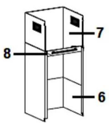
natural_image
Technical line drawing of a mechanical assembly with directional arrows indicating motion (no text or symbols)natural_image
Line drawing of a hand holding a box with a tool, placed on a metal shelf (no text or symbols)X
KAMINHALTEBÜGEL
natural_image
Pure geometric diagram of a symmetrical mechanical or architectural component with no text, numbers, or symbolsRICHTIG
natural_image
Simple line drawing of three stacked rectangles with a vertical centerline (no text or symbols)FALSCH
natural_image
Diagram of a mechanical or fluid system with directional arrows and a central component (no text or symbols)3.3 Aluminium-Fettfilter
Dear customer! We would like to thank you for purchasing a product from our wide range of domestic appliances. Read the complete instruction manual before you operate the appliance for the first time. Retain this instruction manual in a safe place for future reference. If you transfer the appliance to a third party, also hand over this instruction manual.
Index
- Safety instructions....49
1.1 Signal words....50
1.2 Safety instructions....50
- Installation 54
2.1 General installation instructions....54
2.1.1 Scope of delivery....55
2.2 Important installation instructions: extraction mode.... 56
2.3 Minimum distances....56
2.4 View of the appliance 58
2.5 Installation: one way valve / extractor hood.... 58
2.5.1 Installation of the one-way valve.... 59
2.5.2 Installation of the extractor hood 61
2.6 Electrical connection....69
- Recirculation mode / Extraction mode....69
3.1 Extraction mode 69
3.2 Recirculation mode....69
3.2.1 Carbon filters....70
3.3 Aluminium grease filters....72
- Control panel and operation 73
4.1 Control panel....73
4.2 Operation....74
4.2.1 Power levels....76
- Environmental protection .... 77
5.1 Environmental protection: disposal 77
5.2 Environmental protection: energy saving....77
- Cleaning and maintenance....78
6.1 Cleaning of aluminium grease filters....79
6.2 Carbon filters....80
6.3 Replacing of the LED illuminants 81
- Troubleshooting....82
- Technical data.... 84
- Waste management....85
- Guarantee conditions....86
A. Technische Zeichnung / Technical drawing....88

Do not dispose of this appliance together with your domestic waste. The appliance must be disposed of at a collecting centre for recyclable electric and electronic appliances. Do not remove the symbol from the appliance.
The figures in this instruction manual may differ in some details from the current design of your appliance. Nevertheless, follow the instructions in such a case.
i Any modifications, which do not influence the functions of the appliance. shall remain reserved by the manufacturer.
i Please dispose of the packing with respect to your current local and municipal regulations.
The appliance you have purchased may be an enhanced version of the unit this manual was printed for. Nevertheless, the functions and operating conditions are identical. This manual is therefore still valid.
i Technical modifications as well as misprints shall remain reserved.
EU - DECLARATION OF CONFORMITY
★ The products, which are described in this instruction manual, comply with the harmonised regulations.
★ The relevant documents can be requested from the final retailer by the competent authorities.
MAKE SURE THAT THIS MANUAL IS AVAILABLE TO ANYONE USING THE APPLIANCE AND MAKE SURE THAT IT HAS BEEN READ AND UNDERSTOOD PRIOR TO USING THE DEVICE.
WOLKENSTEIN
READ THE SAFETY INFORMATION AND THE SAFETY INSTRUCTIONS CAREFULLY BEFORE YOU OPERATE THE APPLIANCE FOR THE FIRST TIME.
All information included in those pages serve for the protection of the operator. If you ignore the safety instructions, you will endanger your health and life.
Store this manual in a safe place so you can use it whenever it is needed. Strictly observe the instructions to avoid damage to persons and property.
Check the technical periphery of the appliance! Do all wires and connections to the appliance work properly? Or are they time-worn and do not match the technical requirements of the appliance? A check-up of existing and new made connections must be done by an authorised professional. All connections and energy-leading components (incl. wires inside a wall) must be checked by a qualified professional. All modifications to the electrical mains to enable the installation of the appliance must be performed by a qualified professional.
i The appliance is intended for private use only.
i The appliance is intended for extracting/recirculating cooking vapours in private household only.
i The appliance is intended for indoor-use only.
i The appliance is not intended to be operated for commercial purposes, during camping and in public transport.
i Operate the appliance in accordance with its intended use only.
Do not allow anybody who is not familiar with this instruction manual to operate the appliance.
This appliance may be operated by children aged from 8 years and above as well as by persons with reduced physical, sensory and mental capabilities or lack of experience and knowledge if they are supervised or have been instructed concerning the safe use of the appliance and do comprehend the hazard involved. Children must not play with the appliance. Cleaning and user-maintenance must not be carried out by children unless they are supervised.
1.1 Signal words
⚠️ DANGER! indicates a hazardous situation which, if ignored, will result in death or serious injury.
⚠ WARNING! indicates a hazardous situation which, if ignored, could result in death or serious injury.
CAUTION! indicates a hazardous situation which, if not avoided, may result in minor or moderate injury.
NOTICE! indicates possible damage to the appliance.
1.2 Safety instructions
DANGER!
To reduce the risk of electrocution.
- Non-compliance of the orders of this instruction manual will endanger the life and health of the operator and/or can result in damages to the appliance.
- Do not operate the appliance when it does not work properly, is visibly damaged, has dropped down or the power cord/plug are damaged.
- When the power cord is damaged, it must be replaced by the manufacturer or an authorised aftersales service or a qualified professional (electrical engineer) only.
- All electrical work that may be necessary to connect the appliance to the mains must be carried out by a qualified professional (electrical engineer). Do not modify the energy supply. The connection must be carried out in accordance with the current local and legal regulations.
- The technical data of your energy supplier must meet the data on the rating plate of the appliance.
- The appliance contains a gas pressure spring. The gas pressure spring is pressurised and must not be opened. If the gas pressure spring is damaged, it must be replaced by the manufacturer or an authorised aftersales service or a qualified professional (electrical engineer) only. If the gas pressure spring does not operate properly, please contact the aftersales service or the shop you purchased the appliance at. ^14 Original spare parts should be used only.
- Never try to repair the appliance yourself. Repairs carried out by unauthorised persons can cause serious damage. If the appliance
does not operate properly, please contact the aftersales service or the shop you purchased the appliance at. ^15 Original spare parts should be used only.
- In case of an event caused by a technical malfunction, disconnect the appliance from the mains (fuse box of your household power supply). Contact the aftersales service or the shop you purchased the appliance at. ^16 RISK OF ELECTRIC SHOCK!
- Do not operate any room-air dependent fireplaces while operating the appliance; otherwise, harmful gases will get from the fireplace into your home. Whenever the hood is operated together with chimney-vented fireplaces (e.g., coal furnace), ensure there is sufficient air supply in the room where the appliance is installed in. Always consult your local chimney-sweep master. When you operate the appliance in recirculation mode, you can simultaneously run room-air dependent fireplaces.
- If gas is set free in your home:
a) open all windows.
b) do not unplug the appliance and do not use the control panel.
c) do not touch the appliance until the gas has gone.
d) otherwise, sparks can be generated which will ignite the gas.
-
Never pull the power supply cable to unplug the appliance. Always use the power plug itself to unplug the appliance. RISK OF ELECTRIC SHOCK!
-
Never touch the power plug, the power switch or other electrical components with wet or damp hands. RISK OF ELECTRIC SHOCK!
⚠ WARNING!
To reduce the risk of burns, electrocution, fire or injury to persons.
- Whenever you use extractor hoods in combination with non-electrically operated appliances (gas and oil-fired appliances), the negative pressure of the corresponding room must not be more than 4 Pa ( 4 × 10^-5 bar).
- An electrical supply of 220\~240V AC/50Hz is required. Do not use a socket board or a multi socket or an extension cord when operating the appliance with 220\~240V AC/50Hz. All electrical connections which may be damaged must be repaired by a qualified professional.
-
Only connect the appliance to a properly grounded and dedicated socket.
-
The appliance must be grounded. Only use a proper safety socket to minimise risk of electric shock.
-
The technical data of your energy supply must meet the data on the rating label.
-
Your domestic circuit must be equipped with an automatic circuit breaker.
-
Strictly observe the minimum distance between hood and hob. It is also absolutely necessary to observe the individual minimum distances to extractor hoods which are specified in the instruction manual of your hob/oven / etc.
| MINIMUM DISTANCE HOOD TO | |
| ceramic-glass rings / hotplates | min. 45.00 cm |
| gas cookers | min. 55.00 cm |
| coal / oil / stove wood firing | min. 85.00 cm |
-
Never install the appliance below the required minimum distance. If you ignore the required minimum distance, the accumulated fat in the filters can catch fire due to the heat emission of the hob. RISK OF FIRE!
-
The load-bearing capacity of the wall/ceiling ^17 of the installation room must be checked before you install the appliance. The appliance must be installed at a suitable position only.
-
Before you install the appliance, check that there are not any electrical or other cables in the installation area; this prevents these cables from being drilled unintentionally. RISK OF ELECTIC SHOCK!
-
We recommend carrying out the installation of the extractor hood by qualified personnel. Any damage caused by improper installation of the appliance are not subject to the guarantee or warranty!
-
Do not cook a la flambé dishes below the extractor hood. The flames may damage your appliance and/or cause fire.
-
Do not operate the gas jets of a gas hob without cookware. The flames may damage your appliance and/or cause fire.
-
If you fry, permanently keep an eye on the oil as it can catch fire. The risk of auto-ignition rises when using the oil many times.
-
Do not carry out any procedures on the hob using naked light or fire. The flames may damage your appliance and/or cause fire.
-
The exhaust hose (depending on model) must not be made of flammable materials or contain any flammable materials.
-
Operate the appliance with inserted grease filters only. Otherwise,
recirculating-transported fat will deposit in the appliance and the exhaust system. RISK OF FIRE! Clean or replace the filters regularly.
- Disconnect the appliance from the mains before you clean or maintain it.
- Failure to follow the cleaning instructions will increase the RISK OF FIRE due to fat deposits.
- While unpacking, the packaging materials (polythene bags, polystyrene pieces, etc.) should be kept away from children. CHOKING HAZARD! RISK OF INJURY!
- Always supervise children when they are near the appliance.
- Children must not play with the appliance.
- Only allow children to use the appliance without supervision when adequate instructions have been given before so that the child is able to use the appliance in a safe way and understands the risks of improper use.
CAUTION!
- Accessible parts of the hood may become hot while cooking.
- Any potential user must be careful not to hit their head on the corners and edges of the appliance. RISK OF BRUISES! RISK OF INJURIES IN THE OCULAR AREA!
- Carry out the installation of the appliance with at least two persons. Risk of damage. RISK OF INJURY!
NOTICE!
- The appliance must be transported and installed by at least two persons.
- Unpack the parts of the chimney very carefully; otherwise, you will damage the chimney.
- Remove the complete packaging materials before initial operation. The appliance may be equipped with a transportation lock. Remove the transportation lock completely. When removing be very careful. Do not use any aggressive detergents to remove residues of the transportation lock.
- Take the enclosed parts from the packaging and its polystyrene-components.
- Do not use any aggressive, abrasive and acrid detergents or sharpedged items to clean the appliance. Otherwise, you may scratch the surface. RISK OF DAMAGE!
- Clean and maintain the appliance regularly to enable its proper operation and optimal performance.
WOLKENSTEIN
- Check that the power cord and the appliance are not damaged before electrical connection.
- The rating plate must not be removed or made illegible, otherwise all terms of the warranty become invalid!
SAVE THESE INSTRUCTIONS.
★ The manufacturer and distributor are not responsible for any damage or injury in the event of failure to comply with these instructions.
2. Installation
NOTICE! Any damage caused by an appliance that is improperly installed and improperly connected to the mains is not covered by the warranty or guarantee.
We recommend carrying out the installation of the extractor hood by qualified personnel. Damages caused by improper installation of the appliance are not subject to the guarantee or warranty!
2.1 General installation instructions
The load-bearing capacity of the wall/ceiling of the installation room must be checked before you install the appliance.
The appliance must be installed at a suitable position only.
Before you install the appliance, check that there are not any electrical or other cables in the installation area; this prevents these cables from being drilled unintentionally.
Clean the environment thoroughly before installation. This prevents dust or rubble from being sucked in during initial operation of the appliance.
➢ DURING INSTALLATION: ensure that the extractor hood is in horizontal position in order to avoid accumulations of fat in one corner of the appliance.
2.1.1 Scope of delivery
- Ensure that all components listed below (see table) are included in the scope of delivery and are in a proper condition.
| Extractor hood | 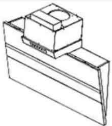 | 1x |
| Inner chimney | 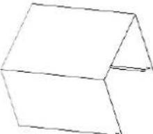 | 1x |
| Outer chimney | 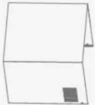 | 1x |
| Exhaust hose (for extraction mode only) | 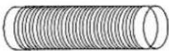 | 1x |
| Inner chimney bracket | 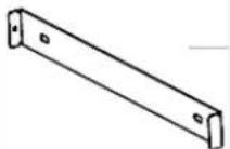 | 1x |
| Wall bracket | 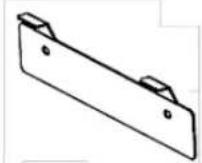 | 1x |
| Chimney bracket | 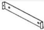 | 1x |
| Dowels | 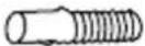 | 6x |
| Screws: ST 4*25 mm | 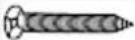 | 6x |
| Screws: ST 4*10 mm |  | 6x |
INSTALLATION OF THE CHIMNEY / RECIRCULATION MODE
The air vents (M) of the upper chimney (K) must face upwards and not be covered by the lower chimney (L). S. fig. below. The air vents in the inner chimney are not available on all appliance models. If your appliance model does not have air vents in the inner chimney, you can skip this poin
2.2 Important installation instructions: extraction mode
⚠ WARNING! Do not lead the exhaust air into a chimney which is used for extracting exhaust air of appliances operated by gas or other combustibles.
For extracting the exhaust air always observe the current legal regulations.
The diameter of the exhaust hose must meet the diameter of the connecting ring.
If your appliance is equipped with a carbon filter, remove the carbon filter before you operate the appliance in the extraction mode. The carbon filter should be used in the recirculating mode only.
The exhaust duct should be as short and straight as possible. The diameter of the exhaust hose should be at least 120/150 mm (look at chapter TECHNICAL DATA). Otherwise, you have to expect increased noise and decreased performance of your appliance.
The proper maximum bending angle outwards is 120^ .
➢ Use smooth tubes or flexible, non-inflammable exhaust hoses only.
When the exhaust duct is connected horizontally, a minimum falling gradient of 1 cm/m or an inclination of 2^ is required. Otherwise, condensate will get into the motor of the hood.
When an exhaust duct is used, the ending of the exhaust hose must be adjusted into the direction of flow.
If the exhaust duct passes through cool areas (e.g., an attic), a temperature gradient may occur in the different parts of the exhaust duct so condensate will be generated. Proper insulation of the corresponding parts of the exhaust duct will then be needed. Equip such an exhaust duct with a condensate trap if need be.
➢ Depending on the appliance model the hood is equipped with one (top) or two (top, back) outlets. The idle outlet is covered by a plastic cap. You can remove this cap by turning it anticlockwise. Use the cap to cover the idle outlet.
2.3 Minimum distances
The minimum distance between the extractor hood and an electric hob must be at least 45.00 cm.
i Strictly observe the minimum distance between the extractor hood and the hob.
i It is also absolutely necessary to observe the individual minimum distances between hobs and extractor hoods; these are specified in the instruction manual of your hob/oven/etc.
REQUIRED MINIMUM DISTANCE HOOD TO
| ceramic-glass rings / hotplates | min. 45.00 cm |
| gas cookers | min. 55.00 cm |
| coal / oil / stove wood firing | min. 85.00 cm |
- The minimum distances do not represent the required total height, but a minimum value generated by adding the height of the hob (floor hob) and the required minimum distance of the hob to the extractor hood (hob extractor hood)
$$ (\text { floor } \leftrightarrow \text { hob }) $$
$$ + \quad (\text { h o b } \leftrightarrow \text { e x t r a c t o r h o o d }) $$
$$ = \text { MINIMUM INSTALLATION HEIGHT } $$
- Adapt the total installation height to the height of the user. Please note that the extraction capacity of the appliance can decrease if installed at a large distance to the hob.
⚠ WARNING! Never install the appliance below the required minimum distance. If you ignore the required minimum distance, the accumulated fat in the filters can catch fire due to the heat emission of the hob. RISK OF FIRE!
⚠️ CAUTION! Any potential user must be careful not to hit their head on the corners and edges of the extractor hood. RISK OF BRUISES! RISK OF INJURIES IN THE OCULAR AREA!
2.4 View of the appliance
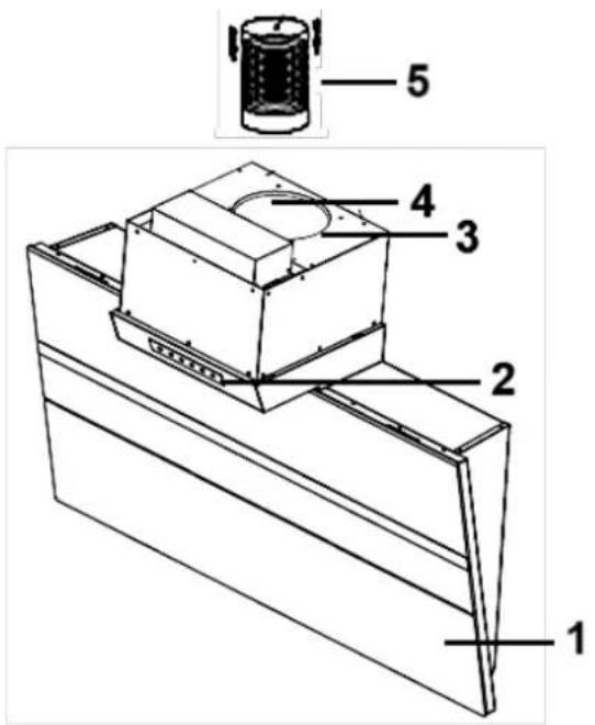
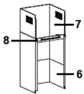
Fig similar: figures serve as examples only.
| 1 | HOUSING OF THE EXTRACTOR HOOD |
| 2 | CONTROL PANEL |
| 3 | EXHAUST AIR OUTLET |
| 4 | ONE-WAY VALVE |
| 5 | EXHAUST HOSE (for extraction mode only) |
| 6 | OUTER CHIMNEY |
| 7 | INNER CHIMNEY |
| 8 | CHIMNEY BRACKET |
2.5 Installation: one way valve/extractor hood
⚠ WARNING! For safety reasons, use only fastening or installation screws of the sizes specified in this instruction manual. Failure to follow the size and installation instructions for screws or mounting devices may result in electrical hazards. RISK OF ELECTRIC SHOCK!
⚠ WARNING! Do not damage the wiring in the wall while drilling. RISK OF ELECTRIC SHOCK!
NOTICE! Two assistants are required for installation.
NOTICE! Any damage caused by an appliance that is improperly installed and improperly connected to the mains is not covered by the warranty or guarantee.
We recommend carrying out the installation of the extractor hood by qualified personnel. Damages caused by improper installation of the appliance are not subject to the guarantee or warranty!
| YOU CAN LAY THE EXHAUST HOSE AS FOLLOWS(FOR EXTRACTION MODE ONLY) | |
| VERTICALLY: lay the exhaust hose to a roof cap*. | 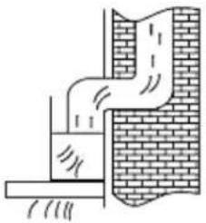 Fig. similar. Fig. similar. |
| HORIZONTALLY: lay the exhaust hose to an exhaust outlet equipped with an air grille*. | 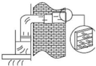 Fig. similar. Fig. similar. |
| * | Article not included in the scope of delivery. |
2.5.1 Installation of the one-way valve
If your appliance does not have the one-way valve installed at the factory, you still need to install it. The following figures only show an example of the standard installation of an one-way valve, as the exhaust air outlet may vary depending on the model and configuration of the appliance.
The one-way valve consists of two flap parts (a / b). You must install both flap parts individually in the housing of the exhaust air outlet (c / s. fig. below).
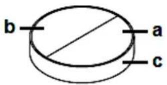
| a | ONE-WAY VALVE: flap part «a» |
| b | ONE-WAY VALVE: flap part «b» |
| c | HOUSING OF THE EXHAUST AIR OUTLET |
INSTALLATION STEPS
- Each of the two individual flap parts (a / b) consist of a semicircle including an axle (d). In the centre of the axle (d) of a flap part is an axle pin (e / s. fig. below).
- Insert the axle (d) of a flap part carefully into the corresponding openings (f / on both sides) in the housing of the exhaust air outlet (c); the axle pin (e) must point upwards (s. fig. below).
- Repeat step 2 for the other flap part.
- Ensure that both parts of the one-way valve are installed properly. The flap parts must not jam or get caught.
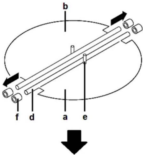
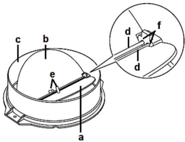
| a | ONE-WAY VALVE: flap part «a» |
| b | ONE-WAY VALVE: flap part «b» |
| c | HOUSING OF THE EXHAUST AIR OUTLET |
| d | AXLES |
| e | AXLE PINS |
| f | OPENINGS in the housing of the exhaust air outlet (on both sides) |
2.5.2 Installation of the extractor hood
INSTALLATION STEPS
The minimum distance between the extractor hood and an electric hob must be at least 45.00 cm.
- Find a suitable position for the extractor hood.
- Measure and mark the positions of the six drill holes required (two for the inner chimney bracket, two for the chimney bracket and two for installing the housing of the extractor hood on the wall). Ensure that the minimum distances are observed.
Note that the position of the screw holes for the fixing of the inner chimney bracket, also represents the highest point of the entire chimney. Screw the inner chimney bracket to the wall using the screws (ST 4*25 mm) and plugs supplied.
WOLKENSTEIN
- Drill two 8 mm ∅ holes to fix the wall bracket (s. fig. below). The wall bracket must be levelled. Check the horizontal alignment with a spirit level. Tighten the suspending bracket using the supplied screws and dowels on the wall.
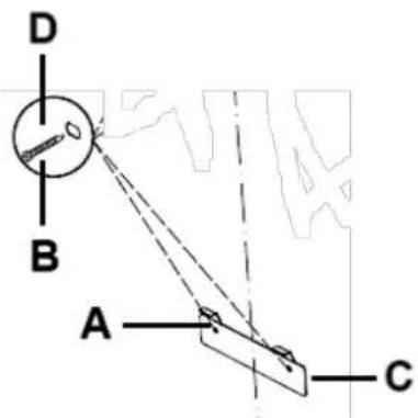
| A | SCREW HOLES (2 pcs. in total) |
| B | EXPANSION DOWELS (2 pcs. in total) |
| C | WALL BRACKET |
| D | SCREWS: ST 4*25 mm (2 pcs. in total) |
- EXTRACTION MODE: connect the exhaust hose (H) to the exhaust air outlet (F) of the extractor hood (E / s. fig. below on the left). Fix the exhaust hose (H) using a cable tie (J / s. fig. below on the right).
RECIRCULATION MODE: please ignore step 4. « EXTRACTION MODE », step 7a. and step 9.; please observe the instructions given in chapter 3.2 RECIRCULATION MODE.
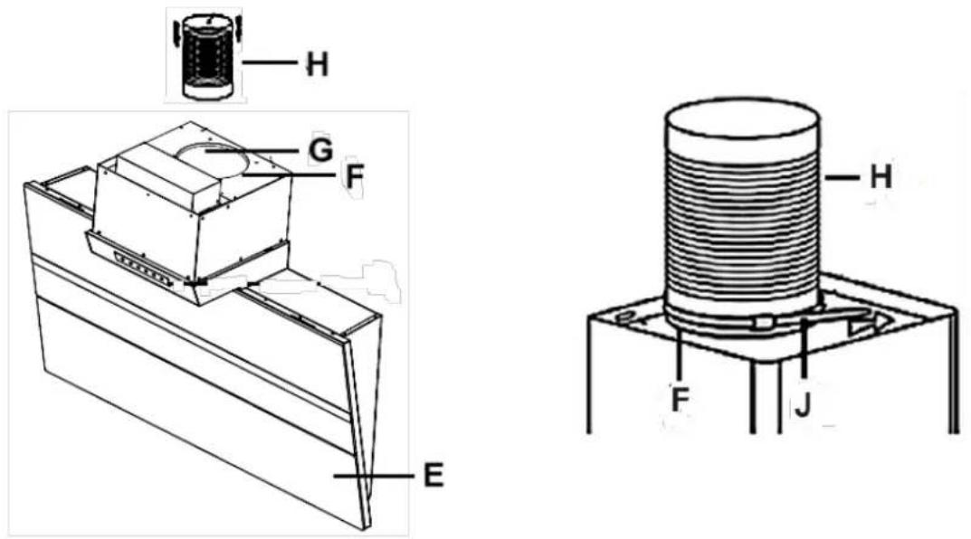
Fig similar: figures serve as examples only.
| E | HOUSING OF THE EXTRACTOR HOOD |
| F | EXHAUST AIR OUTLET |
| G | ONE-WAY VALVE |
| H | EXHAUST HOSE (for extraction mode only) |
| J | CABLE TIE ^18 |
- Install the extractor hood on the wall bracket (s. fig. below). Ensure that the extractor hood is aligned horizontally.
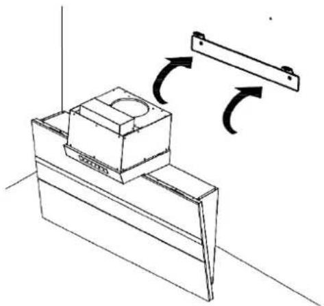
natural_image
Technical line drawing of a mechanical assembly with directional arrows indicating motion (no text or symbols)Fig similar: figure serves as an example only.
- Screw two screws (ST 4*10 mm) into the two safety openings (E1) next to the exhaust air outlet (s. fig. below).
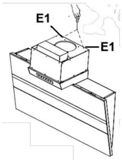
E1
SAFETY OPENINGS (Screws ST 4+10 mm)
- Insert the inner chimney (K) into the outer chimney (L). S. fig. below. Fix the chimney bracket (X) on the outer chimney using the corresponding screws (ST 4*10 mm). Do not tighten the screws too firmly so that the inner chimney (K) remains extendable after installation.
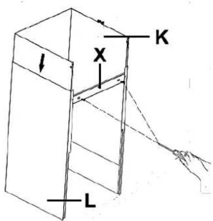
| K | INNER CHIMNEY |
| L | OUTER CHIMNEY |
| X | CHIMNEY BRACKET |
a. INSTALLATION OF THE CHIMNEY / EXTRACTION MODE
The air vents ^19 (M) of the upper chimney (K) must face downwards and be covered by the lower chimney (L). S. fig. below. The air vents in the inner chimney are not available on all appliance models. If your appliance model does not have air vents in the inner chimney, you can skip this point.
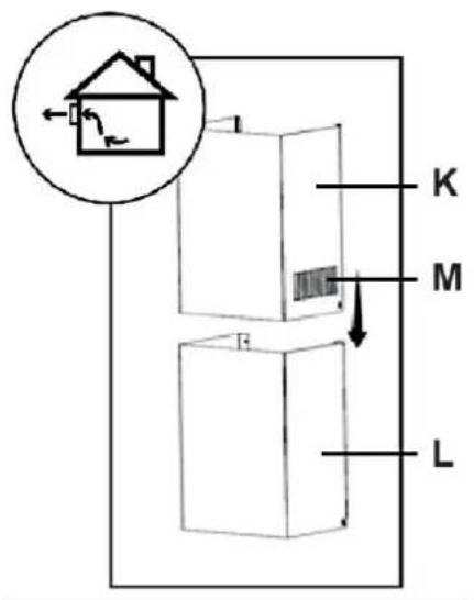
| K | INNER CHIMNEY |
| L | OUTER CHIMNEY |
| M | AIR VENTS |
b. INSTALLATION OF THE CHIMNEY / RECIRCULATION MODE
The air vents (M) of the upper chimney (K) must face upwards and not be covered by the lower chimney (L). S. fig. below. The air vents in the inner chimney are not available on all appliance models. If your appliance model does not have air vents in the inner chimney, you can skip this point.
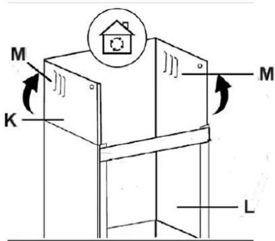
| K | UPPER CHIMNEY |
| L | LOWER CHIMNEY |
| M | AIR VENTS |
- Place the whole chimney (K + L) on the extractor hood (s. fig. below). Fix the chimney bracket (X) on the wall using two screws (ST 4*25 mm / prepared drill holes / s. fig. below).
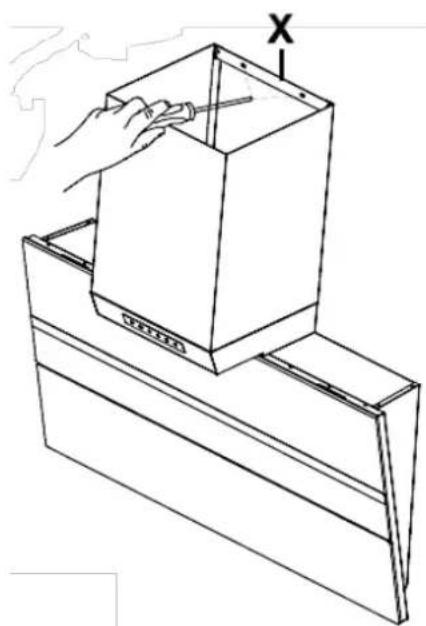
natural_image
Line drawing of a hand holding a box with a tool, placed on a metal shelf (no text or symbols)| X | CHIMNEY BRACKET |
- Guide the exhaust hose (H / for extraction mode only) to the outside (s. fig. below and s. step 8.).
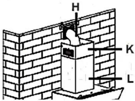
Fig similar: figure serves as an example only.
| H | EXHAUST HOSE (for extraction mode only) |
| K | INNER CHIMNEY |
| L | OUTER CHIMNEY |
- You can lay the exhaust hose as follows (for EXTRACTION MODE ONLY).
| VERTICALLY: lay the exhaust hose to a roof cap*. | 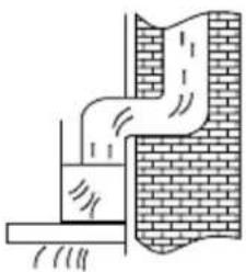 Fig. similar. Fig. similar. |
| HORIZONTALLY: lay the exhaust hose to an exhaust outlet equipped with an air grille*. | 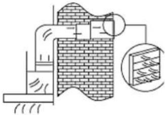 Fig. similar. Fig. similar. |
*
Article not included in the scope of delivery.
- Pull out the upper chimney. Align the chimney according to the installed inner chimney bracket (O / s. fig. below). Fix the inner chimney to the inner chimney bracket (O / s. fig below) using two screws (N = ST 4*10 mm).
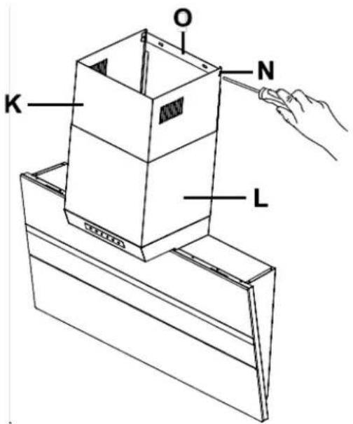
| K | INNER CHIMNEY |
| L | OUTER CHIMNEY |
| N | SCREWS (ST 4*10 mm) |
| O | INNER CHIMNEY BRACKET |
- Install the aluminium grease filter (if not yet installed) and connect the appliance to the mains ^20 . The installation of the aluminium grease filter is described in chapter 6.1 CLEANING OF THE GREASE FILTERS.
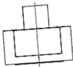
- Check the correct position of the extractor hood from front and side perspective (s. fig below). Otherwise, the appliance will not work properly.
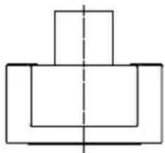
natural_image
Pure geometric diagram of nested rectangles with a dashed centerline (no text or symbols)RIGHT
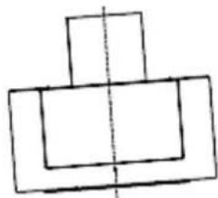
natural_image
Simple line drawing of three stacked rectangles with a vertical centerline (no text or symbols)WRONG
⚠ WARNING! Operate the appliance with inserted grease filters only. Otherwise, recirculating-transported fat will deposit in the appliance and the exhaust system. RISK OF FIRE!
2.6 Electrical connection
Check that the voltage indicated on the rating plate matches the mains voltage of your home before you connect the extractor hood to the mains.
Check that the extractor hood is installed properly before you connect the appliance to the mains.
NOTICE! Any damage caused by an appliance that is improperly connected to the mains is not covered by the warranty or guarantee.
3. Recirculation mode/Extraction mode
3.1 Extraction mode
⚠ WARNING! Do not lead the exhaust air into a chimney which is used for extracting exhaust air of appliances operated by gas or other combustibles.
The extractor hood is usually ready for the use in extraction mode (modifications are possible).
In extraction mode, the intake air is led through an exhaust hose to the outside. For this purpose, an exhaust shaft or an outwardly leading exhaust pipe must be available in your home.
If your appliance is equipped with a carbon filter, you must remove the carbon filter before you operate the appliance in extraction mode!
i If you want to use the extractor hood in extraction mode, please always observe the instructions given in chapter 2. INSTALLATION et seq. and in chapter 2.5.2 INSTALLATION OF THE EXTRACTOR HOOD: step 4. « EXTRACTION MODE », step 7a. and step 9.
3.2 Recirculation mode
You can also use the appliance in recirculation mode.
If you do not use an exhaust air pipe to the outside for the installation of the extractor hood, the exhaust hose is not required.
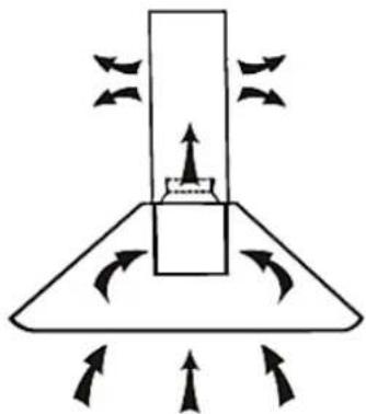
In recirculation mode, the exhaust air is led back into the kitchen (s. fig. below).
If you want to use the extractor hood in recirculation mode, you can install carbon filters (s. chapter 3.2.1 CARBON FILTERS).
In addition to the grease filters (must always be installed), carbon filters also neutralise odours and absorb fine dust particles, etc. In this way, carbon filters additionally improve the exhaust air that is returned to the kitchen. We always recommend the use of carbon filters in recirculation mode.
The installation of the extractor hood is the same as described in chapter 2.5.2 INSTALLATION OF THE EXTRACTOR HOOD (please ignore step 4. «EXTRACTION MODE», step 7a. and step 9).
i Only in recirculation mode you can use CARBON FILTERS to eliminate cooking vapours and odours.
natural_image
Diagram of a mechanical or fluidic component with directional arrows indicating flow or movement (no text or symbols)Fig. similar: fig. serves as an example only.
3.2.1 Carbon filters
Product code: CF190
⚠ WARNING! Carbon filters must be used in recirculation mode only!
NOTICE! Carbon filters are not included in the scope of delivery ^21 .
i Replace the CARBON FILTERS regularly (see also chapter CLEANING AND MAINTENANCE).
i CARBON FILTERS for your extractor hood are optionally available.
You can order the CARBON FILTERS at
www.pkm-online.de
➢ Type name of the CARBON FILTERS: see chapter TECHNICAL DATA
WARNING! Switch off the appliance and disconnect it from the mains before you install any carbon filters (use the relevant fuse in your household fuse box).
HOW TO INSTALL THE CARBON FILTERS
This chapter only describes a common installation of carbon filters in a standard extractor hood. Modifications for different appliance models are possible.
The number of aluminium grease filters depends on the model of the extractor hood. The number of grease filters for your appliance model is indicated in the chapter «TECHNICAL DATA». A standard appliance model with only one grease filter is used here as an example.
- Open the appliance.
- Remove the aluminium grease filter: press the locking button on the handle (C) of the aluminium grease filter to release the grease filter from its lock. Then remove the aluminium grease filter.
Behind the aluminium grease filter is the motor of the appliance. The carbon filters are installed on the motor.
- The CARBON FILTERS are intended to be installed on both sides of the motor.
- Place the CARBON FILTER on the motor and turn it clockwise until it is firmly tightened (s. fig. below).
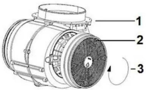
Fig. similar: modifications are possible.
WOLKENSTEIN
| 1 | MOTOR |
| 2 | CARBON FILTER |
| 3 | CLOCKWISE ROTATIONPlace the CARBON FILTER on the motor and turn the filter clockwise until it is installed properly. |
-
Repeat the procedure on the other side of the motor.
-
If you want to uninstall the CARBON FILTERS, turn the filters anti-clockwise and remove them.
-
Reinstall the aluminium grease filter: insert the aluminium grease filter properly into the corresponding slots on the extractor hood. Press and hold the locking button on the grease filter handle while pushing the aluminium grease filter into its proper position. Once the aluminium grease filter is properly in position, release the locking button to lock the grease filter in place.
-
Close the appliance.
⚠ WARNING! Install the carbon filters safely and properly; otherwise, the carbon filters can loosen and cause hazardous situations.
⚠ WARNING! Operate the appliance with inserted aluminium grease filters only. Otherwise, recirculating-transported fat will deposit in the appliance and the exhaust system. RISK OF FIRE!
NOTICE! The suction capacity is decreased by installed carbon filters.
NOTICE! Depending on frequency of use, replace the carbon filters every three to six months. Clean the aluminium grease filter(s) regularly for proper operation of the motor (s. chapter CLEANING AND MAINTENANCE).
3.3 Aluminium grease filters
i Always ensure that the aluminium grease filters ^22 are inserted properly.
i Clean the aluminium grease filters regularly (s. chapter CLEANING AND MAINTENANCE).
⚠ WARNING! Operate the appliance with inserted aluminium grease filters only. Otherwise, recirculating-transported fat will deposit in the appliance and the exhaust system. RISK OF FIRE!
4. Control panel and operation
4.1 Control panel
⚠ WARNING! The LED illuminant must not be covered by thermal insulation or other materials. RISK OF FIRE!
⚠️ CAUTION! Do not touch the LED illuminant within 30 minutes after using the appliance. RISK OF BURNS!
NOTICE! Only switch on the LED illumination while the appliance is operating. Do not switch on the illumination to illuminate the room.
NOTICE! Never press two buttons simultaneously.
CONTROL PANEL
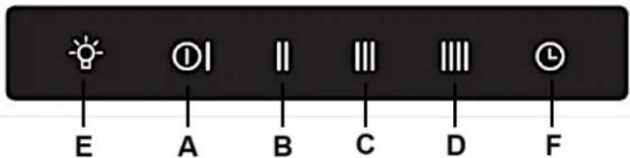
| A |  | «ON/OFF»-SENSOR➢ Sensor to switch on / off the extractor hood.➢ The appliance starts at the lowest level: power level «1». |
| B |  | «POWER LEVEL»-SENSOR➢ Sensor for the activation of power level «2». |
| C |  | «POWER LEVEL»-SENSOR➢ Sensor for the activation of power level «3». |
| D |  | «POWER LEVEL»-SENSOR➢ Sensor for the activation of power level «4». |
| E |  | «ILLUMINATION»-SENSOR➢ Sensor to switch on / off the LED illumination. |
| F |  | «TIMER»-SENSOR➢ Sensor for the activation of the timer. |
4.2 Operation

«ON/OFF»-SENSOR
Use the «ON/OFF»-SENSOR to switch on/off the extractor hood.
HOW TO SWITCH ON THE EXTRACTOR HOOD
- Touch the «ON/OFF Ⓞ»-SENSOR to switch on the extractor hood. If the extractor hood running at the power level «1».
- The appliance starts at the lowest level: power level: «1».
- The extractor hood now is in OPERATION MODE.
i After the extractor hood switched on using the «ON/OFF»-SENSOR, it is always in OPERATION MODE. - Use the «POWER LEVEL»-SENSORS to set the desired power level of the extractor hood (power level 1 - 4).
- The set power level can be changed at any time using the «POWER LEVEL»-SENSORS.
HOW TO SWITCH OFF THE EXTRACTOR HOOD
- Touch the «ON/OFF ①»-SENSOR TWICE to switch off the extractor hood.
- The appliance is now switched off.

«ILLUMINATION»-SENSOR
Use the «ILLUMINATION»-SENSOR to switch on/off the LED ILLUMINATION of the extractor hood.
HOW TO SWITCH ON THE LED ILLUMINATION
- Touch the «ILLUMINATION»-SENSOR once briefly to switch on the LED illumination of the extractor hood.
- The LED illumination is switched on.
How to switch off the LED illumination
- Briefly touch the «ILLUMINATION 📋»-SENSOR once again to switch off the LED illumination of the extractor hood.
- The LED illumination is switched off.
⚠ WARNING! The LED illuminant/illuminants must not be covered by thermal insulation or other materials. RISK OF FIRE!
⚠️ CAUTION! Do not touch the LED illuminant/illuminants within 30 minutes after using the appliance. RISK OF BURNS!
NOTICE! Only switch on the LED illumination while the appliance is operating. Do not switch on the LED illumination to illuminate the room.

TIMER
The extractor hood is equipped with a timer. The countdown time of the timer is set to 5 minutes at the factory and cannot be changed. After the 5 minutes have elapsed, the appliance switches off automatically.
HOW TO ACTIVATE THE TIMER
- Touch the «ON/OFF Ⓞ»-SENSOR to switch on the extractor hood.
- The extractor hood now is in OPERATION MODE.
- Choose the power levels, Touch the «TIMER»-SENSOR.
- The timer is activated.
- The appliance switches off automatically after 5 minutes.
HOW TO DEACTIVATE THE TIMER PREMATURELY
To deactivate the timer prematurely, touch the «TIMER 🔒»-SENSOR again.
4.2.1 Power levels
❖ The extractor hood is equipped with 4 power levels (= 4 motor speeds).
Use the «POWER LEVEL»-SENSORS to set the desired power level (motor speed) of the extractor hood (power level 1 - 4).
The indicator of the currently set power level (1/2/3 or 4) goes on.
1-4
HOW TO SET THE POWER LEVELS «1 - 4»
To set a power level (motor speed), touch the desired «POWER LEVEL»-SENSOR. The indicator of the currently set power level (1/2/3 or 4) goes on.
POWER LEVEL 1 AND 2 = LOW POWER LEVELS
The power levels «1 and 2» are the low power levels (motor speed) of the extractor hood.
These power levels are suitable for slow cooking / simmering and roasting with the lid of the cookware closed.
Use these power levels when very low or low steam generation occurs (very low or low concentration of cooking fumes).
Power level «3» is the medium power level (motor speed) of the extractor hood.
This power level is suitable for standard cooking.
Use this power level for an ideal air circulation in the kitchen when medium steam generation occurs (medium concentration of cooking fumes).
POWER LEVEL 4 = HIGHEST POWER LEVEL
Power level «4» is the highest/maximum power level (motor speed) of the extractor hood.
Use this power level when lots of steam occurs (strong concentration of cooking fumes).
WOLKENSTEIN
5.1 Environmental protection: disposal
Appliances bearing this symbol « 📄 » must not be disposed of together with household waste throughout the EU. To prevent potential damage to the environment or human health from uncontrolled waste disposal and to promote the sustainable reuse of material resources, responsibly supply the appliance to a recycling centre.
5.2 Environmental protection: energy saving
❖ Cover your cookware (cooking pot / pan) with lids during cooking.
The diameter of the cooking pot / pan should meet the diameter of the cooking zone or the size of the flame of the burner (gas appliances).
- Switch off the extractor hood after cooking or use the delayed switch-off function (equipment depends on model).
Only switch on the illuminant while the appliance is in operation. Do not switch on the illuminant to illuminate the room.
❖ Switch off the illuminant(s) of the appliance after cooking.
The power level should always meet the intensity of the generated cooking fumes. Use the highest motor speed of the appliance (highest/maximum power level/booster level) to extract strong concentration of cooking fumes only. A lower power level always means a lower energy consumption.
Make sure there is sufficient supply air to allow the extractor hood to operate efficiently and with low operating noise.
In the case of a strong concentration of cooking fumes select a higher power level early. Cooking fumes which are already distributed in the kitchen may require a longer operation of the extractor hood.
- Clean the aluminium grease filter(s) regularly as clean filters will increase the efficiency of the appliance.
❖ Replace the carbon filters (for recirculation mode only) regularly. Observe the information given on the packaging of the carbon filters.
⚠ WARNING! Disconnect the appliance from the mains before you clean or maintain it. RISK OF ELECTRIC SHOCK!
⚠ WARNING! Ignoring the cleaning and maintenance instructions will cause an increased RISK OF FIRE!
NOTICE! Take off all rings and bracelets before cleaning or maintaining the appliance; otherwise, you will damage the surface of the appliance.
NOTICE! Any damage that is caused to the appliance by a cleaning product will not be fixed free of charge, even if the guarantee period of the appliance is still valid.
- Clean the housing of the appliance with a suitable detergent. Use such a product carefully and economically.
- Do not clean the control panel with a detergent. Use a damp cloth. Otherwise, you may damage the electronic components of the controls.
- Never use any alcohol-containing detergents to clean matt black painted appliances as these detergents cause colour-changes.
- Clean the glass panels ^23 with a suitable detergent only.
- When you clean or replace the grease filters or the carbon filters, also clean all visible components on the bottom of the appliance with a mild, non-acrid and fat-dissolving detergent.
- Do not damage the grid of metal-made grease filters. The colour of the metal surface may change due to frequent cleaning as well as the use of aggressive detergents. Such changes do not influence the capacity of the appliance and are no reason for complaint.
- Do not use any abrasive detergents or vinegar cleaners.
- Do not use a steam cleaner. RISK OF ELECTRIC SHOCK!
SPECIAL INSTRUCTIONS FOR APPLIANCES WITH A STAINLESS-STEEL CASING ^4
To clean stainless-steel surfaces, use a non-abrasive stainless-steel cleaning agent only.
NOTICE! Never use stainless steel cleaner for the direct environment of the control panel or the control panel itself.
NOTICE! Aggressive detergents such as abrasive detergents, vinegar cleaners, etc. damage the surface of the extractor hood.
6.1 Cleaning of aluminium grease filters
⚠ WARNING! Failure to follow the cleaning instructions will increase the RISK OF FIRE due to fat deposits.
NOTICE! The colour of the metal surface may change due to frequent cleaning as well as the use of aggressive detergents. Such changes do not influence the capacity of the appliance and are no reason for complaint.
NOTICE! Do not damage the grid of metal-made (aluminium) grease filters.
i You do not need to replace aluminium grease filters ^25 .
- Clean the aluminium grease filters by hand or in a dishwasher regularly (up to 65 °C).
Do not use any acrid or corrosive detergents.
Do not use any abrasive detergents!
Do not use any alkaline dishwasher-detergents! (pH more than 7).
CLEANING INTERVAL FOR ALUMINIUM GREASE FILTERS
➢ Every 2 - 3 weeks according to the frequency of use of the extractor hood.
HOW TO DEINSTALL / INSTALL THE ALUMINIUM GREASE FILTERS
This section only describes a standard example of uninstalling/installing an aluminium grease filter. Modifications are possible. A standard appliance model with only one grease filter is used here as an example.
- Open the appliance. Behind the cover is the aluminium grease filter.
-
Press the locking button on the handle of the aluminium grease filter to release the grease filter from its lock. Then remove the aluminium grease filter and clean it as described in this chapter.
-
To reinstall the cleaned aluminium grease filter, insert the grease filter properly into the corresponding slots on the extractor hood. Press and hold the locking button on the grease filter handle while pushing the aluminium grease filter into its proper position. Once the aluminium grease filter is properly in position, release the locking button to lock the grease filter in place.
- Close the appliance.
⚠ WARNING! Operate the appliance with inserted aluminium grease filters only. Otherwise, recirculating-transported fat will deposit in the appliance and the exhaust system. RISK OF FIRE!
NOTICE! Any damage caused by an uninstalled or improperly installed aluminium grease filter is not subject to the guarantee
HOW TO CLEAN THE ALUMINIUM GREASE FILTERS MANUALLY
- Soak the aluminium grease filters in warm rinse water (up to 65 °C)
- Then clean the aluminium grease filters with a soft brush. Be careful not to damage the grid of the grease filters.
- AFTER CLEANING: rinse the aluminium grease filters thoroughly using hot water.
- Repeat this process in case of stubborn soilings or deposits.
- Dry the aluminium grease filters properly before you reinstall them.
HOW TO CLEAN THE ALUMINIUM GREASE FILTERS IN THE DISHWASHER
The aluminium grease filters can also be cleaned in the dishwasher: normal programme (up to 65 °C).
Do not put the aluminium grease filters in the dishwasher together with tableware. Dry the aluminium grease filters properly before you reinstall them.
NOTICE! Aluminium grease filters which are blocked with food leftovers are not covered by the guarantee.
6.2 Carbon filters
WARNING! Switch off the appliance and disconnect it from the mains before you install any carbon filters (use the relevant fuse in your household fuse box).
i CARBON FILTERS for your extractor hood are optionally available.
◆ Conventional carbon filters cannot be cleaned.
The capacity of these filters is limited. You can use such filters for about 3 - 6 months approx.
❖ Replace used filters immediately. Find further information on the filter packaging.
REPLACEMENT INTERVAL FOR CARBON FILTERS
➢ At least every 3-6 months according to the frequency of use of the extractor hood.
You can order the CARBON FILTERS at
www.pkm-online.de
➢ Type name of the CARBON FILTERS: see chapter TECHNICAL DATA
6.3 Replacing of the LED illuminants
⚠ WARNING! LED illuminants must be replaced by a competent person only. Do not carry out the replacement of an LED illuminant yourself. If the LED illuminants are damaged, please contact a qualified professional (electrical engineer): not covered by the guarantee!
⚠ WARNING! Switch off the appliance and disconnect it from the mains before you replace LED illuminants (use the relevant fuse in your household fuse box).
NOTICE! Do not touch the LED illuminant with your hands. The sweat on your fingers will reduce the operating time of your new LED illuminant. Use a thin cloth or a thin glove.
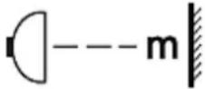 | Required minimum distance to surfaces such as pot lids, oven cloths etc. to avoid any hot parts and risk of fire. |
| --- m = 0.45 m | |
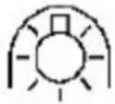 | Only use self-shielded illuminants to avoid hot parts, risk of fire and exposure to UV-radiation. |
NOTICE! Any damage caused by improper and incorrect replacement of the LED illuminants is not subject to the guarantee!
7. Troubleshooting
| MALFUNCTION | |
| POSSIBLE CAUSE | MEASURE |
| THE APPLIANCE DOES NOT WORK AT ALL. | |
| 1. The plug of the appliance is not connected to the socket.2. The plug has become loose.3. The socket is not supplied with energy.4. The fuse is switched off.5. The voltage is too low. | 1. Connect the appliance to the mains properly.2. Check the plug.3. Check the corresponding socket by connecting it with another appliance.4. Check the fuse box.5. Compare the data on the model plate with the data of your energy supplier. |
| THE ILLUMINANT IS ON BUT THE MOTOR DOES NOT WORK. | |
| 1. Ventilation damper blocked.2. Motor mounting defective. | 1. Remove blockage.2. Replace motor. |
| ABNORMAL MOTOR-SMELLS. | |
| 1. Motor defective. | 1. Replace motor. |
| SMEAR OF OIL. | |
| 1. One-way valve is leaky. | 1. Seal the valve. |
| THE APPLIANCE VIBRATES. | |
| 1. Motor not properly fixed.2. Hood not properly fixed. | 1. Fix motor properly.2. Fix hood properly. |
| INSUFFICIENT EXTRACTING CAPACITY. | |
| 1. Too much distance hood-hob.2. Too much draught because of open doors and/or windows. | 1. Lower position of hood.2. Close the doors / windows. |
| THE APPLIANCE IS UNSTABLE. | |
| 1. Screws are not firmly tightened.2. The mounting bracket/mounting plate is not fixed firmly. | 1. Tighten the screws.2. Fix the mounting bracket/mounting plate properly. |
| THE ILLUMINANTS DO NOT WORK. | |
| 1. The extractor hood is not switched on.2. One or all illuminants are defective. | 1. Switch on the extractor hood.2. Replace the defective illuminants. See chapter «REPLACING OF THE LED ILLUMINANTS».PLEASE NOTE:LED illuminantsmustbe replaced by a qualified professional (electrical engineer) only. |
If the appliance shows a malfunction not noted on the schedule above or if you have checked all items on the schedule but the problem still exists, please contact the aftersales service.
IF THE HOOD DOES NOT WORK PROPERLY AND/OR YOU CAN HEAR INCREASED OPERATING NOISE, CHECK THE SCHEDULE BELOW.
IN EXTRACTION MODE
▶ Incorrect dimension of the air duct.
Obstruction in the air duct.
The diameter of the air duct from hood to wall-box inclusive should be 120/150 mm (see chapter «TECHNICAL DATA»); otherwise, the capacity of the motor may be decreased.
If you have installed a fly screen on the wall-box, the air vent may be obstructed. Check by removing the fly screen.
If the cover panel of the wall box is equipped with firm and slanted slats, the air vent may be obstructed. Check by removing the cover panel.
➢ Install a cover panel with moveable slats, which do not obstruct the air vent.
➢ Check condition and cleanliness of the filters.
➢ Check if the air which is extracted by the hood is replaced to avoid negative pressure.
IN RECIRCULATION MODE
➢ Check condition and cleanliness of the filters.
When you run your appliance in recirculation mode, check if the carbon filter has been replaced on time (min. every 3 - 6 months).
If the appliance shows a malfunction not noted on the schedule above or if you have checked all items on the schedule but the problem still exists, please contact the aftersales service.
8. Technical data
TECHNICAL DATA*
| Type | Extractor hood | |
| Material | Black glass, stainless steel | |
| Installation-width in cm | 89,60 | |
| Distance to the hob (minimum) in cm | min. 45.00 | |
| Wall installation | yes | |
| Touch Control / gesture control | yes | no |
| Recirculation / extraction mode** | yes | yes |
| Annual energy consumption (AEC _hood ) | 16.80 kWh/year | |
| Energy efficiency category*** | A+ | |
| Fluid dynamical efficiency (FDE _hood ) | 30.90 | |
| Fluid dynamical efficiency category | A | |
| Lighting efficiency (LE _hood ) | 15 lux/W | |
| Lighting efficiency category | D | |
| Grease separation | 53,3 % | |
| Grease separation category | E | |
| Air flow **** | 321,30 m ^3 /h | 513.60 m ^3 /h |
| Air flow during operation at intensive a intensive or rapid operation setting | - | |
| A-rated noise emission **** | 56 dB | 66 dB |
| A-rated noise emission during operation at intensive or rapid operation setting | - | |
| Connected load | 101W | |
| Lighting system | LED | |
| Power consumption per illuminant | 2*3,00 W | |
| Voltage / frequency | AC 220 – 240 V / 50 Hz | |
| Grease filter / material / dishwasher-proof | 2*MF90 aluminium yes | |
| Carbon filter **** | 2*CF190 / optionally available | |
| Display | no | |
| Supplied accessory: exhaust hose | yes | |
| Supplied accessory: one-way valve | yes | |
| Supplied accessory: installation material | yes | |
| Supplied accessory: instruction manual | yes | |
| Telescopic chimney extractable from-to | 40.00 - 78.00 cm | |
| Total height incl. telescopic chimney | 132.70 cm | |
| Dimensions: appliance H*W*D in cm | 94,70 - 132.70*89.60*29.50 | |
| Weight net / gross in kg | 18.90 / 21.70 | |
◆ Technical modifications reserved.
| * | According to Regulation (EU) No. 65/2014 |
| ** | Extraction mode: installation with ventilation stack or air duct outwards only, wall penetration = 150 mm ∅, drilling approx. 160 mm ∅. |
| *** | On a scale from A+++ (highest) to D (lowest). |
| **** | Measured values at minimum / maximum motor speed. |
| ***** | Optional equipment. |
9. Waste management
- While unpacking, the packaging materials (polythene bags, polystyrene pieces, etc.) should be kept away from children and pets. CHOKING HAZARD! RISK OF INJURY!
- Old and unused appliances must be sent for disposal to the responsible recycling centre. Never expose to open flames.
- Before you dispose of an old appliance, render it inoperative. Unplug the appliance and cut off the entire power cord. Dispose of the power cord and the plug immediately.
- Dispose of any paper and cardboard into the corresponding containers.
- Dispose of any plastics into the corresponding containers.
- If suitable containers are not available at your residential area, dispose of these materials at a suitable municipal collection point for waste-recycling.
- Receive more detailed information from your retailer or your municipal facilities.

Materials marked with this recyclable.
symbol are
Please contact your local authorities to receive further information.
WOLKENSTEIN

This appliance includes a 24-month guarantee for the consumer given by the manufacturer, dated from the day of purchase, referring to its flawless material-components and its faultless fabrication. The consumer is accredited with both the dues of the guarantee given by the manufacturer and the vendor's guarantees. These are not restricted to the manufacturer's guarantee.
Any guarantee claim has to be made immediately after the detection and within 24 months after the delivery to the first ultimate vendee. The guarantee claim has to be verified by the vendee by submitting a proof of purchase including the date of purchase and/or the date of delivery. The guarantee does not establish any entitlement to withdraw from the purchase contract or for a price reduction. Replaced components or exchanged appliances demise to us as our property.
The guarantee claim does not cover:
- fragile components as plastic, glass or bulbs;
- minor modifications of the WOLKENSTEIN-products concerning their authorised condition if they do not influence the utility value of the product;
- damage caused by handling errors or false operation;
- damage caused by aggressive environmental conditions, chemicals, detergents;
- damage caused by non-professional installation and haulage;
- damage caused by non-common household use;
- damages which have been caused outside the appliance by a WOLKENSTEIN-product unless a liability is forced by legal regulations.
The validity of the guarantee will be terminated if:
- the prescriptions of the installation and operation of the appliance are not observed.
- the appliance is repaired by a non-professional.
- the appliance is damaged by the vendor, the installer or a third party.
- the installation or the start-up is performed inappropriately.
- the maintenance is inadequately or incorrectly performed.
- the appliance is not used for its intended purpose.
- the appliance is damaged by force majeure or natural disasters, including, but with not being limited to fires or explosions.
Please provide the following information for the registration of your guarantee claim:
- the complete address of the location of the appliance.
- phone number(s) and e-mail contact.
- model name.
-
serial number/photo of the rating plate.
-
type of malfunction.
i If you do not provide the above data, your guarantee claim cannot be handled immediately.
SPECIAL NOTE
Please photograph the rating plate of the appliance before installation and save the photo for possible later use.
You find the rating plate on the following locations.
- Fridges/freezer: inside or on the back side.
- Dishwasher/washer/dryer: on the door area or the back side.
- Hobs: on the bottom side.
- Ovens: on the door area.
- Hob/oven combinations have 2 rating plates (oven and hob).
- Extractor hoods: inside near the motor.
The guarantee claims neither extend the guarantee period nor initiate a new guarantee period. The geographical scope of the guarantee is limited with respect to appliances, which are purchased and used in Germany, Austria, Belgium, Luxembourg and the Netherlands.
WOLKENSTEIN
August 2014
i All dimensions are given in millimetres.
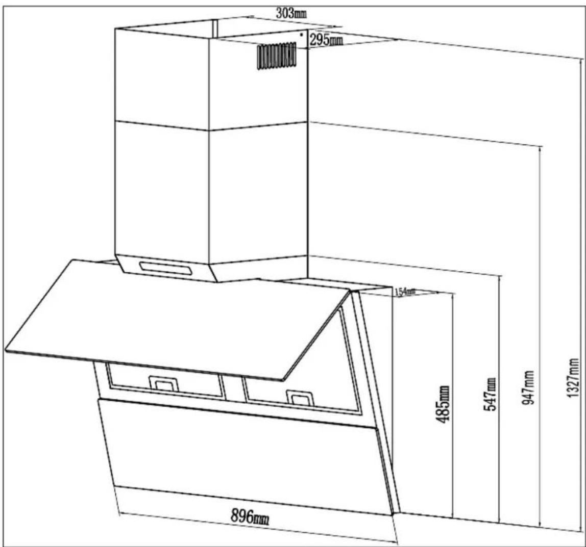
WOLKENSTEIN
SERVICE INFORMATION
Aftersales service information on the leaflet inside this instruction manual.


- Aluminium-Fettfilter
- Index
- EU - DECLARATION OF CONFORMITY
- READ THE SAFETY INFORMATION AND THE SAFETY INSTRUCTIONS CAREFULLY BEFORE YOU OPERATE THE APPLIANCE FOR THE FIRST TIME.
- Signal words
- Safety instructions
- DANGER!
- To reduce the risk of electrocution.
- ⚠ WARNING!
- To reduce the risk of burns, electrocution, fire or injury to persons.
- CAUTION!
- NOTICE!
- WOLKENSTEIN
- SAVE THESE INSTRUCTIONS.
- Installation
- General installation instructions
- Scope of delivery
- INSTALLATION OF THE CHIMNEY / RECIRCULATION MODE
- Important installation instructions: extraction mode
- Minimum distances
- View of the appliance
- Installation: one way valve/extractor hood
- ⚠ WARNING! Do not damage the wiring in the wall while drilling. RISK OF ELECTRIC SHOCK!
- Installation of the one-way valve
- INSTALLATION STEPS
- Installation of the extractor hood
- a. INSTALLATION OF THE CHIMNEY / EXTRACTION MODE
- b. INSTALLATION OF THE CHIMNEY / RECIRCULATION MODE
- Electrical connection
- Recirculation mode/Extraction mode
- Extraction mode
- Recirculation mode
- Carbon filters
- HOW TO INSTALL THE CARBON FILTERS
- Aluminium grease filters
- Control panel and operation
- Control panel
- Operation
- HOW TO SWITCH ON THE EXTRACTOR HOOD
- HOW TO SWITCH OFF THE EXTRACTOR HOOD
- HOW TO SWITCH ON THE LED ILLUMINATION
- How to switch off the LED illumination
- TIMER
- HOW TO ACTIVATE THE TIMER
- HOW TO DEACTIVATE THE TIMER PREMATURELY
- Power levels
- 1-4
- HOW TO SET THE POWER LEVELS «1 - 4»
- POWER LEVEL 1 AND 2 = LOW POWER LEVELS
- POWER LEVEL 4 = HIGHEST POWER LEVEL
- Environmental protection: disposal
- Environmental protection: energy saving
- Cleaning of aluminium grease filters
- CLEANING INTERVAL FOR ALUMINIUM GREASE FILTERS
- HOW TO DEINSTALL / INSTALL THE ALUMINIUM GREASE FILTERS
- HOW TO CLEAN THE ALUMINIUM GREASE FILTERS MANUALLY
- HOW TO CLEAN THE ALUMINIUM GREASE FILTERS IN THE DISHWASHER
- Carbon filters
- REPLACEMENT INTERVAL FOR CARBON FILTERS
- Replacing of the LED illuminants
- Troubleshooting
- IF THE HOOD DOES NOT WORK PROPERLY AND/OR YOU CAN HEAR INCREASED OPERATING NOISE, CHECK THE SCHEDULE BELOW.
- IN EXTRACTION MODE
- IN RECIRCULATION MODE
- Technical data
- Waste management
- The guarantee claim does not cover:
- The validity of the guarantee will be terminated if:
- Please provide the following information for the registration of your guarantee claim:
- SPECIAL NOTE
Brand : Wolkenstein
Model : WS49-90B
Category : Range hood