
EVOLVE-WMK-NB - Uncategorized ELECTRO-VOICE - Free user manual and instructions
Find the device manual for free EVOLVE-WMK-NB ELECTRO-VOICE in PDF.


| Product Type | Wall mount kit for EVOLVE column speakers |
| Model | EVOLVE-WMK-NB |
| Color | Black |
| Connector Type | NL4 |
| Dimensions (H x W x D) | 80 mm x 400 mm x 400 mm (3.1 in x 15.75 in x 15.75 in) |
| Net Weight | 1.35 kg (3.0 lbs) |
| Shipping Weight | 1.8 kg (4.0 lbs) |
| Working Load Limit (WLL) | 5 kg (11 lbs) |
| Environmental Rating | Indoor use only |
| Compatible Loudspeakers | EVOLVE 30M, EVOLVE 50, EVOLVE 50M |
| Adjustment Range (Tilt) | 15° downward |
| Adjustment Range (Pan) | 45° left and right |
| Recommended Cable Gauge | 1.5 mm² – 2.5 mm² (AWG16 – AWG14) |
| Secondary Safety Attachment | Includes secondary auxiliary support cable |
| Subwoofer Adapter Provided | Yes, with NL4 connector |
| Column Speaker Adapter Provided | Yes, with NL4 connector |
| Included Components | Wall bracket, covers, adapters, support cable, rubber grommets, manual |
| Maintenance | Inspect annually for signs of weakness or damage; clean with dry cloth |
| Safety Standard | Designed for overhead suspension; follow local regulations |
| Warranty | Refer to Electro-Voice warranty policy |
Frequently Asked Questions - EVOLVE-WMK-NB ELECTRO-VOICE
User questions about EVOLVE-WMK-NB ELECTRO-VOICE
0 question about this device. Answer the ones you know or ask your own.
Ask a new question about this device
Download the instructions for your Uncategorized in PDF format for free! Find your manual EVOLVE-WMK-NB - ELECTRO-VOICE and take your electronic device back in hand. On this page are published all the documents necessary for the use of your device. EVOLVE-WMK-NB by ELECTRO-VOICE.
USER MANUAL EVOLVE-WMK-NB ELECTRO-VOICE
EVOLVE Wall mount kit
EVOLVE-WMK-PB, EVOLVE-WMK-PW, EVOLVE-WMK-NB, EVOLVE-WMK-NW, EVOLVE-TM-B
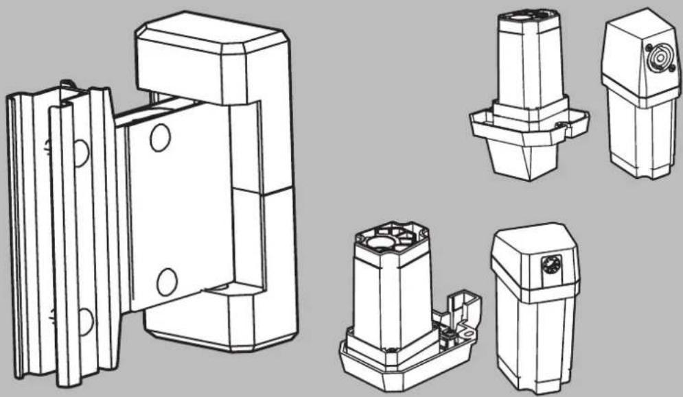
Table of contents
| 1 | Safety 4 | |
| 1.1 Suspension 4 | ||
| 1.2 Notices 4 | ||
| 2 | Short information 6 | |
| 3 | Introduction 7 | |
| 3.1 System features 7 | ||
| 3.2 Packing list 9 | ||
| 4 | Wiring and installation 11 | |
| 4.1 Wiring the EVOLVE column 12 | ||
| 4.2 Attaching the column speaker adapter to the EVOLVE column 15 | ||
| 4.3 Attaching the EVOLVE column to the wall bracket 15 | ||
| 4.3.1 Installing the wall part 16 | ||
| 4.3.2 Attaching the handle part to the EVOLVE column | 17 | |
| 4.3.3 Mounting the wall bracket | 18 | |
| 4.3.4 Attaching the cosmetic cover set | 19 | |
| 4.4 Attaching the EVOLVE column to the truss mount bracket | 20 | |
| 4.5 Wiring the subwoofer | 23 | |
| 4.6 Installing the subwoofer amplifier input cover | 25 | |
| 5 | Troubleshooting | 27 |
| 6 | Technical data 28 | |
| 6.1 Additional pin-out tables | 28 | |
| 6.2 Dimensions | 29 | |
1 Safety
1.1 Suspension

Warning!
Read and fully understand this manual and all safety instructions before attempting to suspend the loudspeaker.

Warning!
Suspending any object is potentially dangerous and should only be attempted by individuals who have a thorough knowledge of the techniques and regulations of suspending objects overhead. Electro-Voice strongly recommends that loudspeakers be suspended taking into account all current national, federal, state, and local laws and regulations. It is the responsibility of the installer to ensure all loudspeakers are safely installed in accordance with all such requirements. When loudspeakers are suspended, Electro-Voice strongly recommends the system be inspected at least once per year or as laws and regulations require. If any sign of weakness or damage is detected, remedial action should be taken immediately. The user is responsible for making sure the wall, ceiling, or structure is capable of supporting all objects suspended overhead. Any hardware used to suspend a loudspeaker not associated with Electro-Voice is the responsibility of others.
Safety point
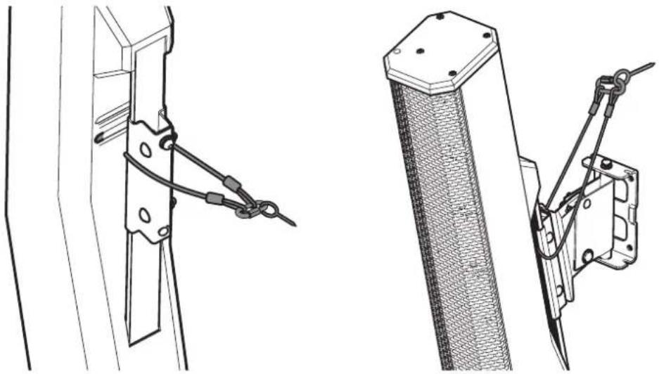
As an added safety measure, Electro-Voice recommends the user install and secure the secondary auxiliary support cable to a different structural support point. This safety point should have as little slack as possible (less than 25 mm/1 in. is preferable).
natural_image
Technical line drawings of mechanical clamping components (no text or symbols)1.2 Notices

Old electrical and electronic appliances
Electrical or electronic devices that are no longer serviceable must be collected separately and sent for environmentally compatible recycling (in accordance with the European Waste Electrical and Electronic Equipment Directive).
To dispose of old electrical or electronic devices, you should use the return and collection systems put in place in the country concerned.
Copyright and disclaimer
All rights reserved. No part of this document may be reproduced or transmitted in any form by any means, electronic, mechanical, photocopying, recording, or otherwise, without the prior written permission of the publisher. For information on getting permission for reprints and excerpts, contact Electro-Voice.
All content including specifications, data, and illustrations in this manual are subject to change without prior notice.
For China only
SJ/T 11364-2014
| (Pb) | (Hg) | (Cd) | (Cr 6+) | (PBB) | (PBDE) | |
| (PCB) | o | o | o | o | o | o |
| x | o | x | o | o | o | |
| x | o | o | o | o | o | |
| x | o | o | o | o | o | |
| o | o | o | o | o | o | |
| o | o | o | o | o | o | |
| x | o | o | o | o | o | |
| SJ/T 11364GB/T 26572GB/T 26572, : | ||||||
QA PASS
合格证
2 Short information
The following table lists products in a family, with CTN (Commercial Type Number) and identifying product name DESCRIPTION.
| Part number CTN Description | ||
| F.01U.392.641 | EVOLVE-WMK-PB EV | OLVE Wall mount kit, Phoenix, black |
| F.01U.392.642 | EVOLVE-WMK-PW EV | OLVE Wall mount kit, Phoenix, white |
| F.01U.392.643 | EVOLVE-WMK-NB EV | OLVE Wall mount kit, NL4, black |
| F.01U.392.644 | EVOLVE-WMK-NW EV | OLVE Wall mount kit, NL4, white |
| F.01U.395.777 | EVOLVE-TM-B Truss | mount, EVOLVE, black |
3 Introduction
Thank you for choosing an Electro-Voice wall mount kit for your EVOLVE column speaker system. Please take time to consult this manual to understand all the features and requirements of the EVOLVE Wall Mount Kit. This is necessary to ensure proper use of the wall mount kit and to provide the highest level of acoustic performance, reliability and safety. Electro-Voice strongly recommends that loudspeakers be suspended taking into account all current national, federal, state and local laws and regulations. Suspending any object is potentially dangerous. Only individuals who have thorough knowledge of the techniques and regulations of suspending objects overhead should attempt to suspend loudspeakers. The Electro-Voice EVOLVE Wall Mount Kit provides users the flexibility to mount the EVOLVE column speaker remotely from the subwoofer and without the distance pole. This provides a safe method for mounting the column speakers higher than the distance pole allows and remote locating the subwoofer for aesthetic or acoustic purposes. The installation can be permanent with the wall mount bracket, or temporary to a truss with the truss mount kit. The wall mount kit is available in both black and white colors to match the EVOLVE columns speaker system and the venue. Both permanent installation friendly Phoenix-style connectors internal to the adapters and easy to use NL4 adapters are available in each color. The truss mount kit allows the EVOLVE column to be clamped to trusses when needed and is available with NL4 adapters.
3.1 System features
EVOLVE-WMK-PB / EVOLVE-WMK-PW
– Innovative mount system is included for quick, simple, and reliable installations of EVOLVE column speakers.
- Sturdy wall mount bracket with 15 degrees of downward tilt, and 45 degrees, each way, of left and right adjustment.
- Subwoofer and column adapters with internally secured PCB screw terminal blocks.
- Compatible with EVOLVE 30M, EVOLVE 50 and EVOLVE 50M column speakers, available in black or white.
- Suggested to use correctly rated speaker cable for installation: wire gauges 1.5 ~mm^2 - 2.5 ~mm^2 (AWG16-AWG14).
EVOLVE-WMK-NB / EVOLVE-WMK-NW
- Innovative mount system is included for quick, simple, and reliable installations of EVOLVE column speakers.
- Sturdy wall mount bracket with 15 degrees of downward tilt, and 45 degrees, each way, of left and right adjustment.
- Subwoofer and column adapters with NL4 connections.
- Compatible with EVOLVE 30M, EVOLVE 50 and EVOLVE 50M column speakers, available in black or white.
- Suggested to use correctly rated speaker cable for installation: wire gauges 1.5 ~mm^2 - 2.5 ~mm^2 (AWG16-AWG14).
EVOLVE-TM-B
- Innovative mount system is included for quick, simple, and reliable installations of EVOLVE column speakers to trusses.
- Sturdy truss mount bracket works with M10 threaded studs found on common truss clamps.
-
Subwoofer and column adapters with NL4 connections.
-
Compatible with EVOLVE 30M, EVOLVE 50 and EVOLVE 50M column speakers, available in black.
- Suggested to use correctly rated speaker cable for installation: wire gauges 1.5 mm ^2 - 2.5 mm ^2 (AWG16-AWG14).
- For use with truss clamps rated for WLL= 20 kg (44 lb) SF = 5:1.
3.2 Packing list
EVOLVE-WMK-PB / EVOLVE-WMK-PW
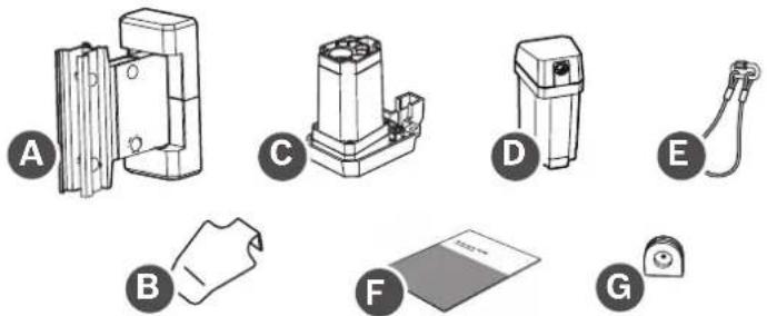
natural_image
Illustration of various electronic components and devices labeled A through G, including a connector and paper sheet (no text or symbols on parts)| Item Quantity | Component | |
| A 1 Wall mount | bracket | |
| B 1 Subwoofer | amplifier input | cover |
| C 1 Column speaker adapter | ||
| D 1 Subwoofer | adapter | |
| E 1 Secondary | auxiliary support cable | |
| F 1 Installation | manual | |
| G 2 Rubber grommets | ||
Table 3.1: Components list for EVOLVE-WMK with Phoenix-style connector
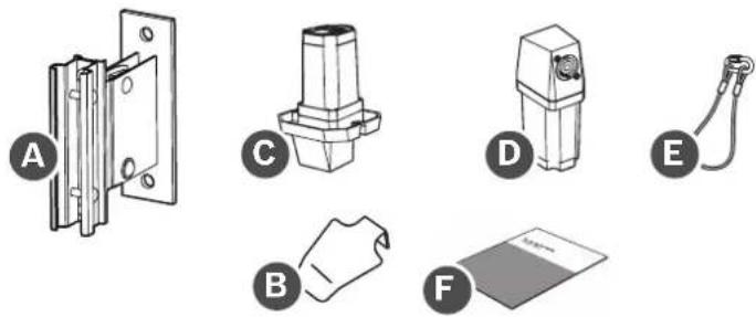
EVOLVE-WMK-NB / EVOLVE-WMK-NW
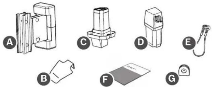
natural_image
Illustration of six different mechanical or electronic components labeled A through G, with no visible text or symbols.| Item Quantity | Component | |
| A 1 Wall mount | bracket | |
| B 1 Subwoofer | amplifier input | cover |
| C 1 Column speaker adapter | ||
| D 1 Subwoofer | adapter | |
| E 1 Secondary | auxiliary support cable | |
| F 1 Installation | manual | |
| G 2 Rubber grommets | ||
Table 3.2: Components list for EVOLVE-WMK with NL4 connector
EVOLVE-TM-B
natural_image
Illustration of six different electronic components or connectors, labeled A through F, with no visible text or symbols.| Item Quantity | Component | |
| A 1 Truss mount, EVOLVE, black | ||
| B 1 Subwoofer | amplifier input | cover |
| C 1 Column speaker adapter | ||
| D 1 Subwoofer | adapter | |
| E 1 Secondary | auxiliary support | cable |
| F 1 Installation | manual | |
Table 3.3: Components list for EVOLVE-TM-B
4 Wiring and installation
| The EVOLVE-WMK is used to suspend EVOLVE 30M, EVOLVE 50 and EVOLVE 50M column speakers remotely from the subwoofer and without the distance pole. | |
 | Warning!The EVOLVE-WMK is designed to only suspend EVOLVE 30M, EVOLVE 50 and EVOLVE 50M column speakers (maximum 11 lbs/5 kg load weight). Do not use to suspend any other loudspeakers or additional equipment. |
| For safety, ensure the mounting surface supports more than the weight of the speaker. Use only industry-accepted fasteners and mounting methods when mounting the wall bracket. Consult an expert if you are unsure. | |
 | Caution!It is the installer's responsibility to determine and use the proper mounting hardware for the wall construction type.Disregarding this caution could result in damage to the product and personal injuries may occur. |
 | Caution!It is the installer's responsibility to determine and use properly rated truss clamps with truss system.Disregarding this caution could result in damage to the product and personal injuries may occur. |
 | Notice!If the loudspeaker installation will be delayed, cover it with the paint shield/dust shield. |
4.1 Wiring the EVOLVE column
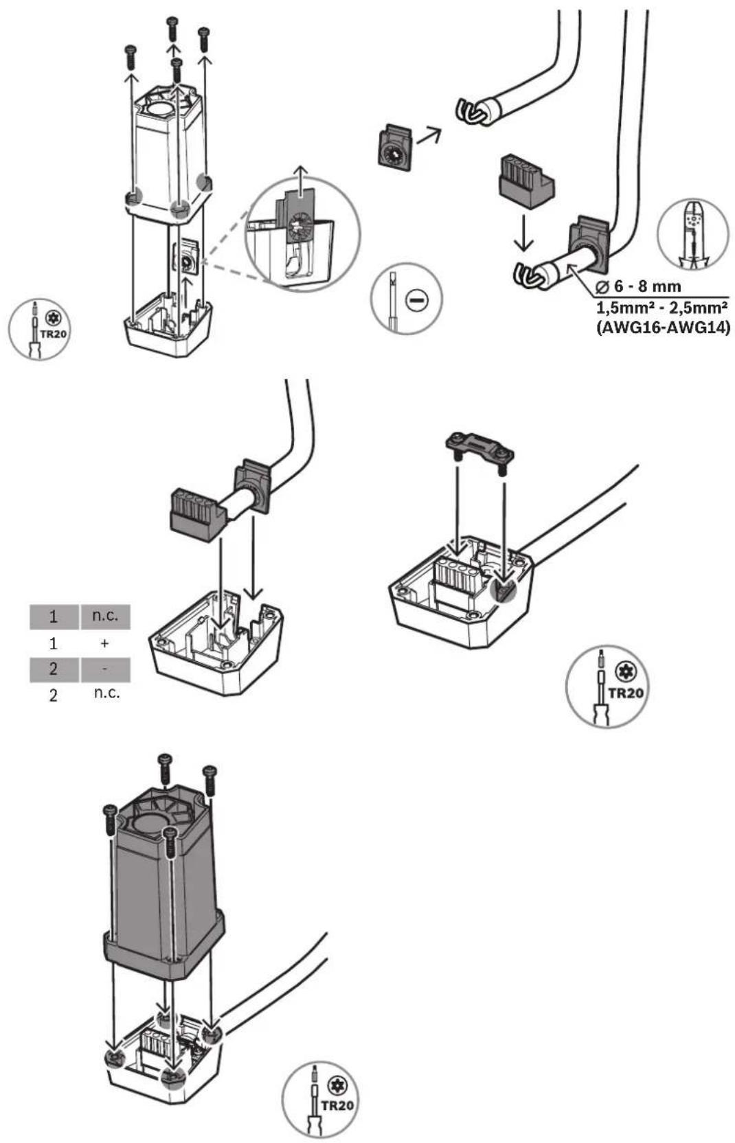
The process of wiring the EVOLVE column is different depending on the connection type of the wall mount kit, as described in this section.
To wire the EVOLVE column to the column speaker adapter:
EVOLVE-WMK-NB / EVOLVE-WMK-NW / EVOLVE-TM-B
- Connect the cable using an NL4 connector to the corresponding NL4 connector on the column speaker adapter.
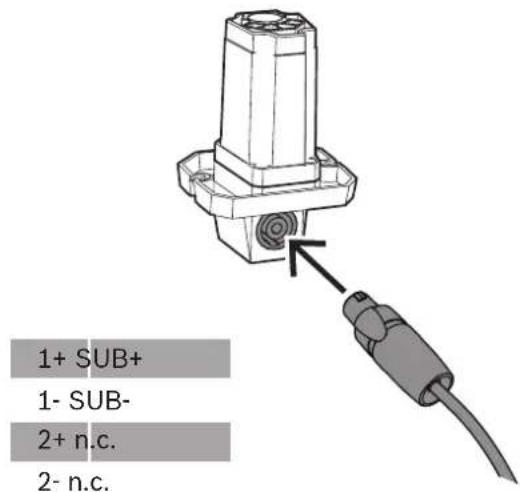
EVOLVE-WMK-PB / EVOLVE-WMK-PW
- Remove the four screws that attach the upper housing of the column speaker adapter to the lower housing.
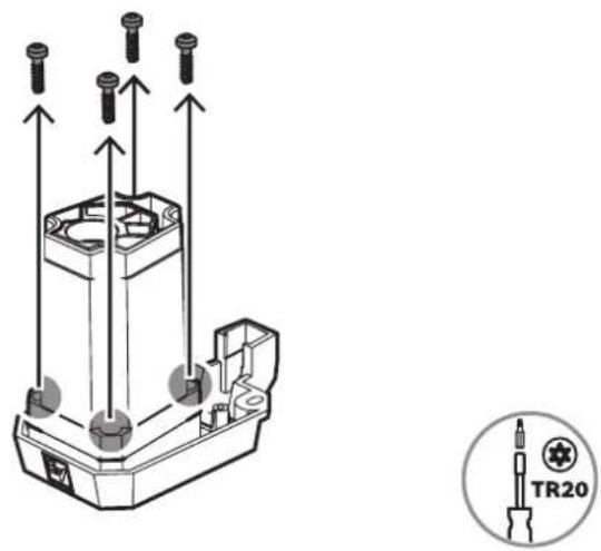
- Strip back each individual wire's insulation to leave approximately 6 mm of bare wire exposed.
- Twist the wire ends to prevent individual strands from separating.
- Insert the bare wire into the input terminal connector.
Make sure no excess bare wire is exposed beyond the terminal connector. The connector must clamp down on the bare wire, not the wire insulation.
- Install the rubber grommet on the cable and attach the Phoenix-style connector to the wire. Connect the positive wire to the pin marked with a "+" +, and the negative wire to the pin marked with a "-" -
- Plug the connector into the lower housing of the column speaker adapter.
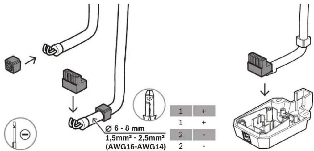
- Attach the strain relief clamp using TR20 screws.
- Replace the upper housing of the column speaker adapter onto the set.
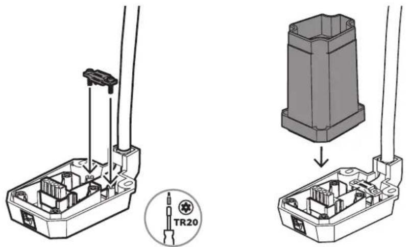
- Attach the upper housing of the column speaker adapter to the lower housing with the supplied screws.
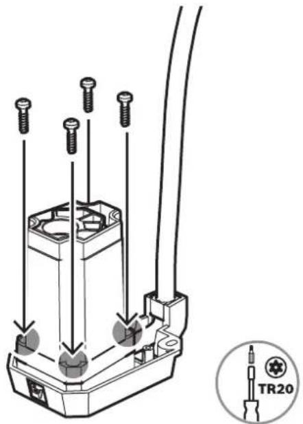
If you're connecting a Phoenix to an NL4, refer to Additional pin-out tables, page 28.
Refer to
- Additional pin-out tables, page 28
4.2 Attaching the column speaker adapter to the EVOLVE column
To attach the column speaker adapter to the EVOLVE column:
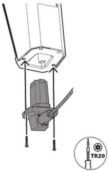
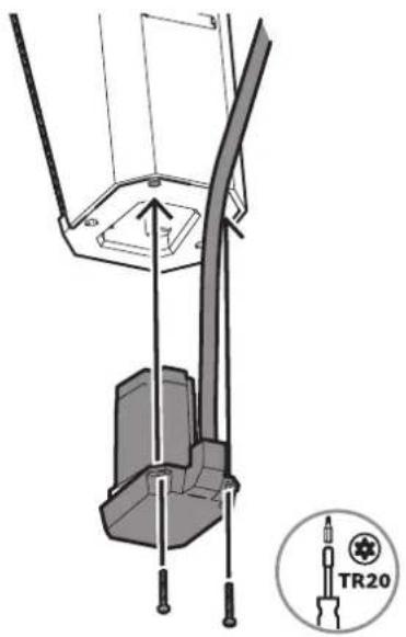
- Remove the two screws on the bottom of the EVOLVE column.
- Insert the column speaker adapter in the opening at the bottom of the EVOLVE column.
- Attach the column speaker adapter to the EVOLVE column with the supplied TR20 screws.
EVOLVE-WMK-NB / EVOLVE-WMK-NW / EVOLVE-TM-B
EVOLVE-WMK-PB / EVOLVE-WMK-PW
4.3 Attaching the EVOLVE column to the wall bracket
The wall bracket is composed of two pieces: the wall part and the handle part. The installation of the wall bracket comprises:
- Installing the wall part, page 16
- Attaching the handle part to the EVOLVE column, page 17
- Mounting the wall bracket, page 18
- Attaching the cosmetic cover set, page 19
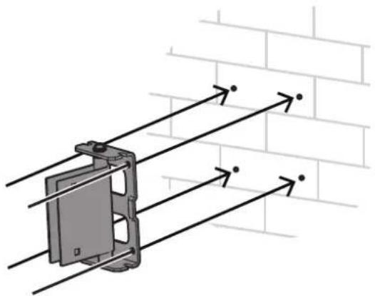
4.3.1 Installing the wall part
To install the wall part of the bracket:
- Separate the two pieces of the wall bracket by unscrewing the two bolts on the side.
- Use a bubble level to align the wall part on the wall.
- Mark the position of the screw holes with a pen.
- Attach the wall part to the wall with the mounting screws.
natural_image
Diagram of a device mounted on a wall with directional arrows indicating alignment or force (no text or symbols present)
Notice!
Consult an engineer and install fasteners according to the hardware manufacturer.

Caution!
It is the installer's responsibility to determine and use the proper mounting hardware for the wall construction type.
Disregarding this caution could result in damage to the product and personal injuries may occur.
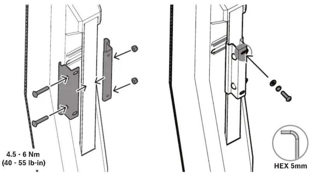
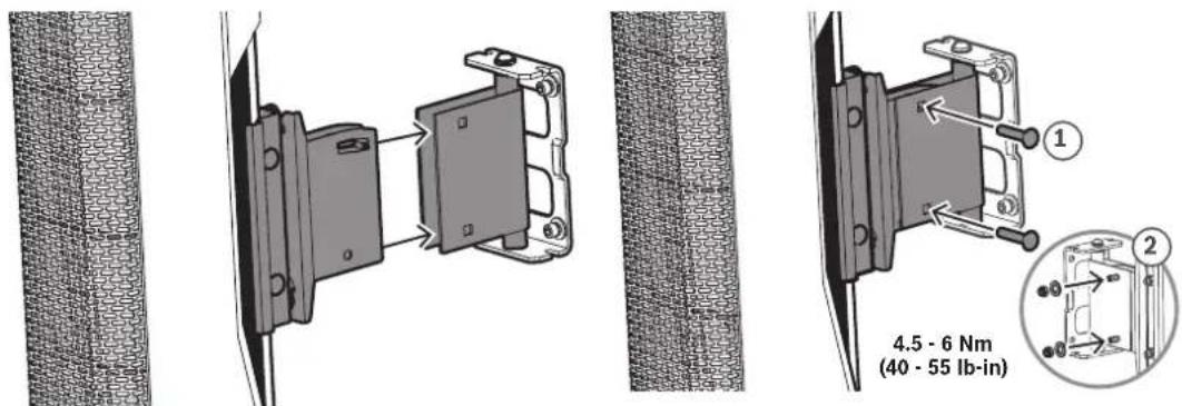
4.3.2 Attaching the handle part to the EVOLVE column
To attach the handle part of the bracket to the EVOLVE column:
- Attach and secure the clips to the back of the EVOLVE column with two screws and nuts.
- Install the screw at the top of the clips. Do not fully insert the screw until the handle part is in place.

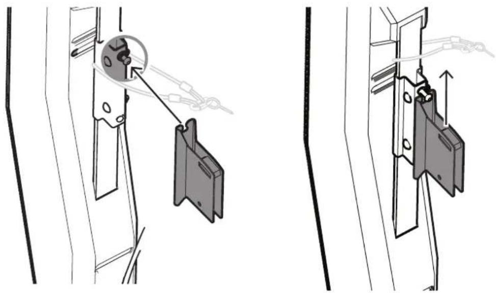
Notice!
Safety point
As an added safety measure, Electro-Voice recommends the user install and secure the secondary auxiliary support cable to a different structural support point. This safety point should have as little slack as possible (less than 25 mm/1 in. is preferable).
- Slide the top screw of the clips down the slit of the handle part.
natural_image
Technical illustration showing two mechanical assembly steps with a magnified inset of a component (no text or symbols)- Install the screw at the bottom of the clips.
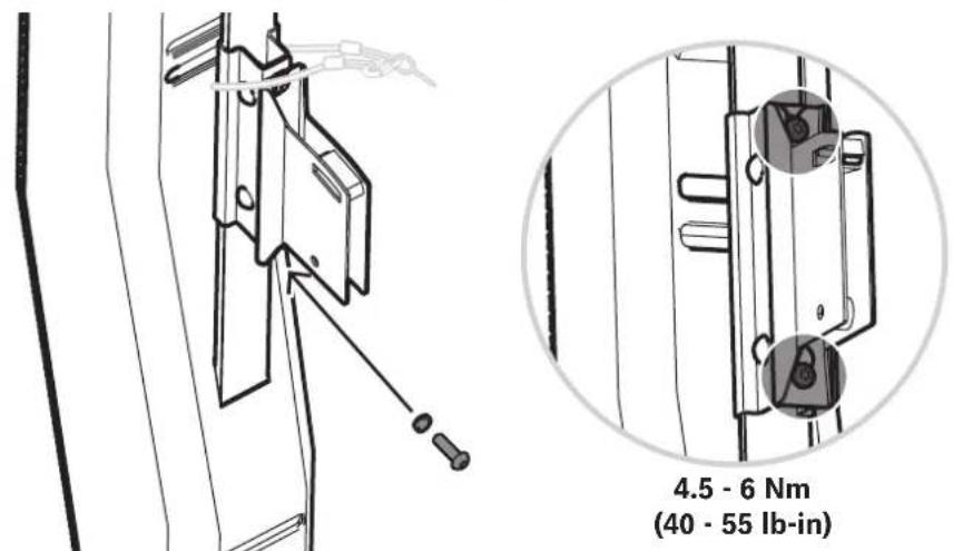
4.3.3 Mounting the wall bracket
To mount the wall bracket:
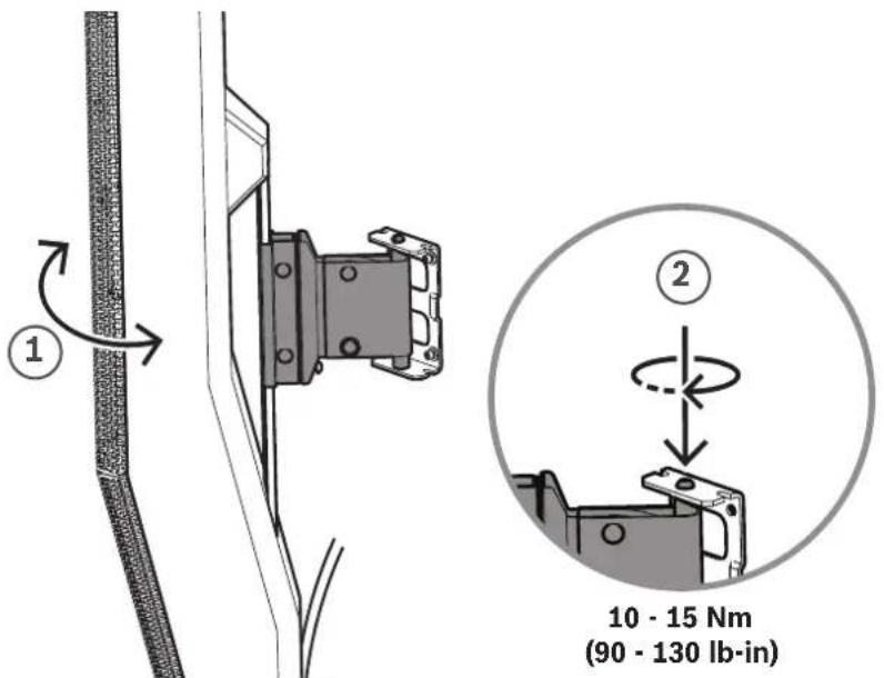
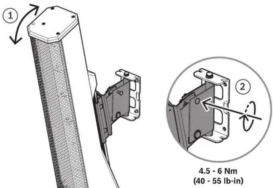
- Attach the handle part to the wall bracket and join both pieces by reinstalling the two bolts.
- When the speaker is in the proper pan angle (1) position, tighten the wall mount screw (2) to lock it in place.
- When the speaker is in the proper tilt angle (1) position, tighten the wall mount screw (2) to lock it in place.
4.3.4 Attaching the cosmetic cover set
To attach the cosmetic cover set onto the bracket:
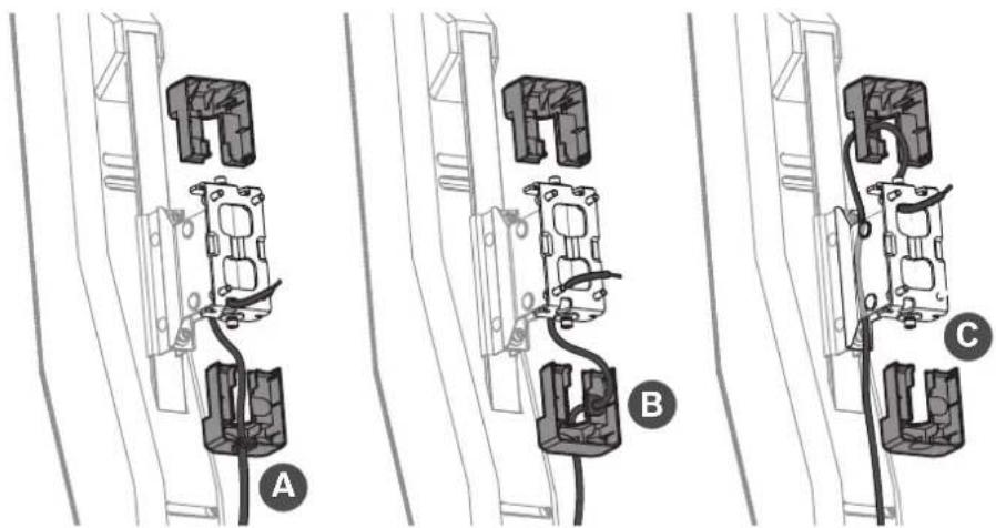
- Cut out one or two slots on the cosmetic cover set to route the cable, as needed.
The area to be cut out will be of a thinner material.
- Install the supplied rubber grommets.
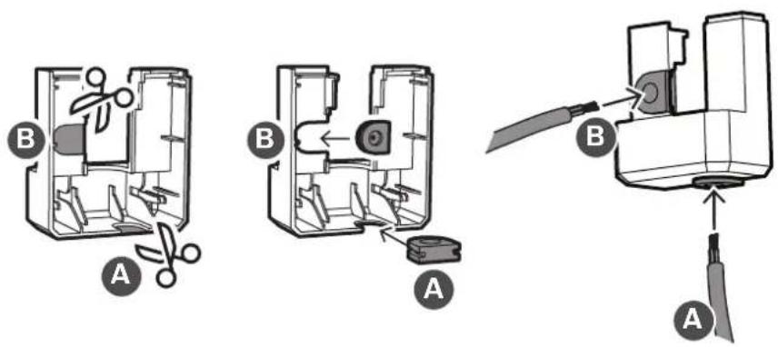
- Route the cable and attach the cosmetic cover set onto the bracket. There are at least three options to route the cable.
4.4 Attaching the EVOLVE column to the truss mount bracket
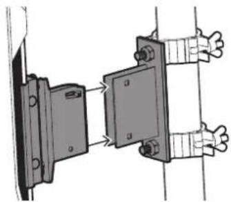
The truss mount bracket is composed of two pieces: the truss part and the handle part. 1. Screw the truss mount bracket to the truss mount clamps using the top and bottom screw holes.
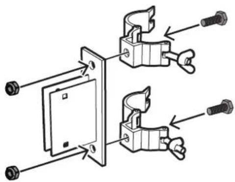

Notice! Use two truss mount clamps with M10 threaded studs rated for 20 kg (44 lb) working load limit (WLL) or greater and 5:1 safety factor (SF).
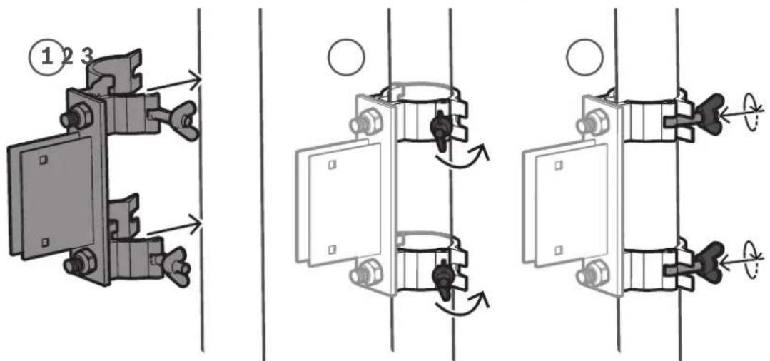
- Attach the truss mount bracket with clamps to the desired support point.
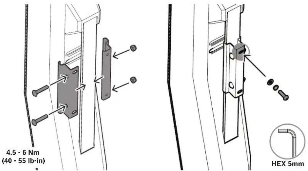
- Attach and secure the clips to the back of the EVOLVE column with two screws and nuts.
- Install the screw at the top of the clips. Do not fully insert the screw until the handle part of the truss mount bracket is in place.

Notice!
Safety point
As an added safety measure, Electro-Voice recommends the user install and secure the secondary auxiliary support cable to a different structural support point. This safety point should have as little slack as possible (less than 25 mm/1 in. is preferable).
- Slide the top screw of the clips down the slit of the handle part of the truss mount bracket.
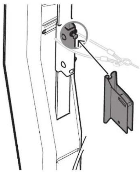
natural_image
Diagram showing a mechanical assembly with a pulley and hanging weights (no text or symbols)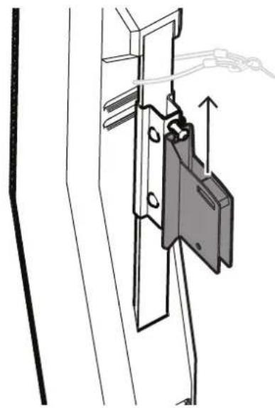
natural_image
Technical line drawing of a mechanical assembly with a clamping mechanism (no text or symbols)- Install the screw at the bottom of the clips.

natural_image
Technical line drawing of a mechanical assembly with no visible text or symbols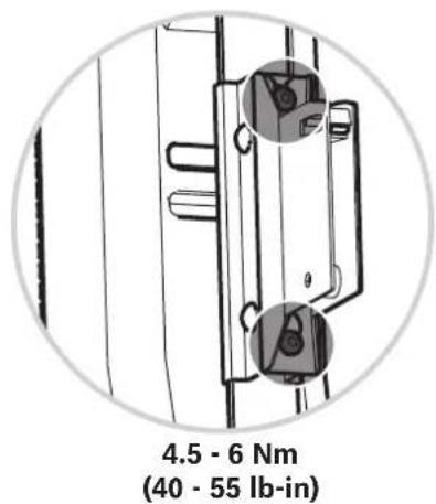
- Attach the EVOLVE column to the truss mount bracket and join both pieces by reinstalling the two bolts.
natural_image
Diagram of two mechanical components connected by a rod, showing alignment and assembly (no text or symbols)
natural_image
Close-up of a woven textile or mesh structure with no visible text or symbols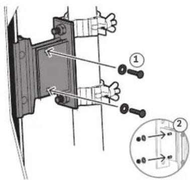
4.5 Wiring the subwoofer
The process of wiring the subwoofer is different depending on the connection type of the wall mount kit, as described in this section.
To wire the subwoofer to the subwoofer adapter:
EVOLVE-WMK-NB / EVOLVE-WMK-NW / EVOLVE-TM-B
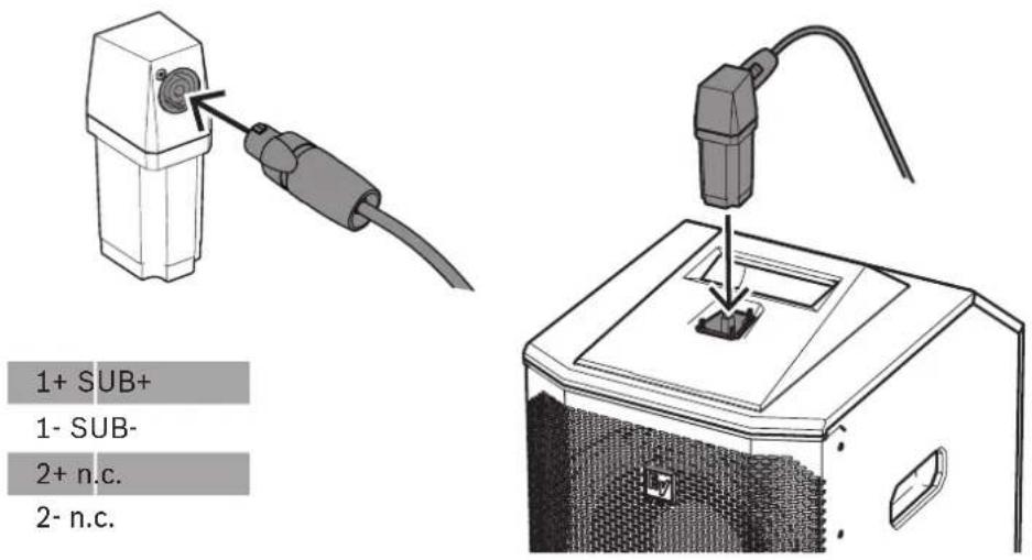
- Connect the cable using an NL4 connector to the corresponding NL4 connector on the subwoofer adapter.
- Plug the subwoofer adapter by inserting it in the slot on the upper part of the subwoofer.
EVOLVE-WMK-PB / EVOLVE-WMK-PW
- Follow the steps described in Wiring the EVOLVE column, page 12.
- Plug the subwoofer adapter by inserting it in the slot on the upper part of the subwoofer.
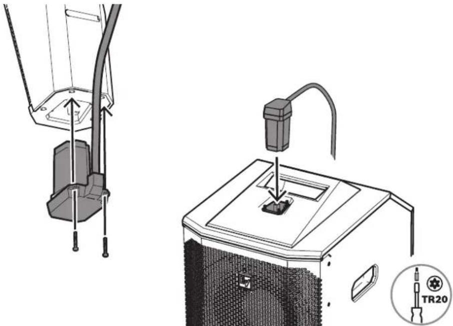
natural_image
Technical illustration of a device with cable and plug assembly, showing internal components and a close-up view of the base (no text or symbols)If you're connecting a Phoenix to an NL4, refer to Additional pin-out tables, page 28.
Refer to
- Wiring the EVOLVE column, page 12
4.6 Installing the subwoofer amplifier input cover
The subwoofer amplifier input cover is included with the EVOLVE-WMK to provide protection from dust and occasional light moisture, such as splashes. The cover will also block the light from the LCD display when needed.

Warning!
Do not use the subwoofer amplifier input cover outdoors in wet or damp environments. The cover does not protect the amplifier from rain.
To install the subwoofer amplifier input cover:
- Wrap the cloth around the handle of the subwoofer.
- Attach the hook and loop.
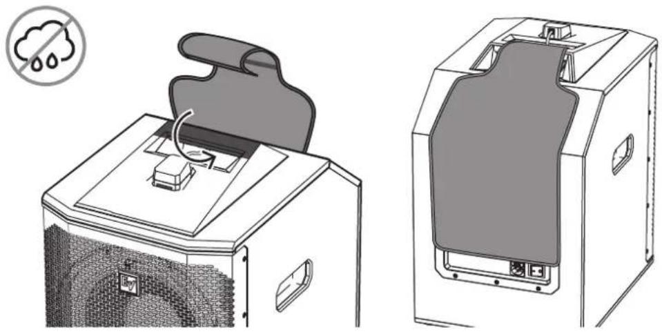
5 Troubleshooting
| Problem Possible Causes Action | ||
| No Sound Amplifier | Connect a known working test speaker to the amplifier outputs. If there is no sound, check all electronics are on, the signal routing is correct, the source is active; the volume is turned up, and so on. Correct/Repair/Replace as necessary. If there is sound, the problem is in the wiring. | |
| Wiring Verify you have connected the correct wire pairs to the amplifier. Play something at low level through the amplifier (for example, from a CD player or tuner). Connect the test speaker in parallel with the malfunctioning line. If the sound has gone or is very weak, the line has a short in it (possibly a severe scrape, pinch, or staple puncture). If the sound level is normal the wire is open (possibly a cut wire or missed connection). Using the test speaker, move down the line and test each connection/junction until you find the problem and correct it. Observe proper polarity. | ||
| Poor Low-Frequency Response | Speakers Wired Out-of-Polarity | When two speakers are connected out of polarity (out of phase), the low frequencies will cancel each other acoustically. Carefully observe the wire markings or tracers on your speaker wires. Verify the amplifier (+) terminal is connected to the red speaker terminals and the amplifier (-) terminal is connected to the black speaker terminals. |
| Improperly Wired Subwoofer Panel | Using a test speaker as described above, verify all amplifier and speaker wires are connected to their proper terminals with the correct polarity. Reversing just one set of amplifier wires can cut out all bass output from the subwoofer. | |
| Intermittent Output such as, Crackling or Distortion | Faulty Connection Check all connections at amplifier and speakers to ensure they are clean and tight. If the problem persists, it may be in the amplifier or wiring. See other actions above. | |
| Constant Noise such as Buzzing, Hissing, Humming | Defective Amplifier or other Electronic Device | If the noise is present but no program material is playing, the likely cause is the signal chain in the electronics. Evaluate each component as necessary to isolate the problem. |
| Poor System Grounding or Ground Loop | Check and correct the system grounding, as required. | |
If these suggestions do not solve your problem, contact your nearest Electro-Voice dealer or Electro-Voice distributor.
6 Technical data
| EVOLVE-WMK-PB/PW | EVOLVE-WMK-NB/NW | EVOLVE-TM-B | |
| Connectors: Phoenix style NL4 | |||
| Environmental: Indoor | |||
| Color: Black or white Black | |||
| Dimensions(H x W x D): | 80 mm x 400 mm x 400 mm (3.1 in. x 15.75 in. x 15.75 in) | ||
| WLL: 5 kg (11.0 lbs) | |||
| Net weight: 1.35 kg (3.0 lbs) | |||
| Shipping weight: 1.8 kg (4.0 lbs) | |||
6.1 Additional pin-out tables
| Column Phoenix NL4 | ||
| Positive connection | 1 n.c. | |
| 1 | +1 | |
| Negative connection | 2 | -1 |
| 2 n.c. | ||
| Subwoofer | Phoenix NL4 | |
| Positive connection | n.c. | n.c. |
| 1 | +1 | |
| Negative connection | 2 | -1 |
| n.c | n.c. |
6.2 Dimensions
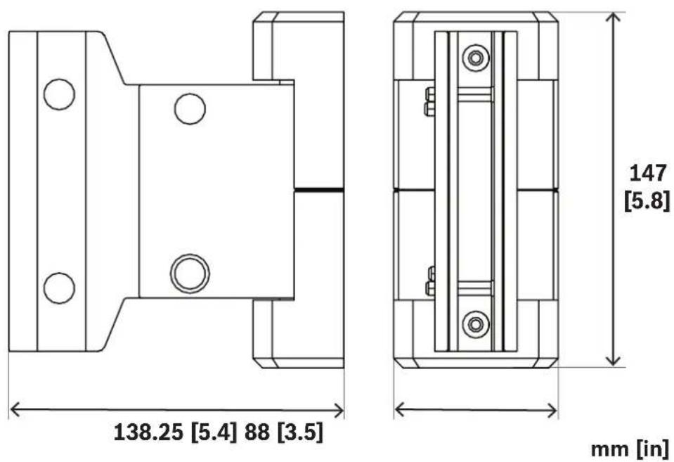
Figure 6.1: Wall mount bracket
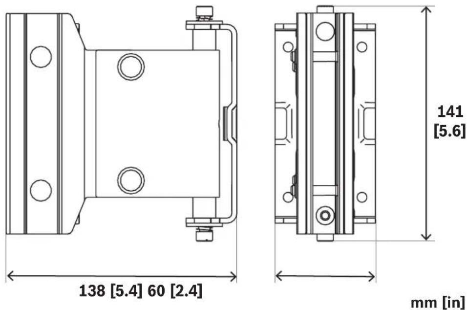
Figure 6.2: Wall mount bracket without covers
![108.7 [42.8]](/content/2026/05/912350/images/15a2110212648a9a142ae1da674d9bcd4981e93fd5fa9493d7b6cf75f2759e55.jpg)
![99 [39] 64 [25.2] mm [in]](/content/2026/05/912350/images/23f9297c462eb1d10c5adf0de741e40f55e56ac588bf7d45236fab17a58ab148.jpg)
Figure 6.3: Column speaker adapter for EVOLVE-WMK with Phoenix-style connector
![55 [2.2] 48.4 [1.9] mm [in] 103 [4]](/content/2026/05/912350/images/18512de7bfb09cb7f31c3dc3f74480349c7568f7845d80b95f8eadc93ba1b376.jpg)
Figure 6.4: Subwoofer adapter for EVOLVE-WMK with Phoenix-style connector
![129 [5.08] 77 [3.03] 85 [3.34] EY](/content/2026/05/912350/images/60359f82e7a0d3e25b9fe3fee40090a287aaed753b19a4a337dc0b1d41289168.jpg)
Figure 6.5: Column speaker adapter for EVOLVE-WMK with NL4 connector
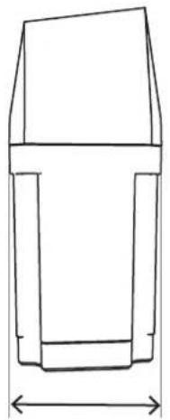
natural_image
Simple line drawing of a mechanical part with no text or symbols![130 [5.1]](/content/2026/05/912350/images/6c373052cf9cf927fa1be2976810d17ff6d11bcf4c53621f52a1197f057b746e.jpg)
48.4 [1.9]
mm [in]!
Figure 6.6: Subwoofer adapter for EVOLVE-WMK with NL4 connector
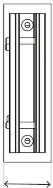
natural_image
Technical line drawing of a door frame with internal compartments and mounting holes (no text or symbols)72 [28]
![150 [109]](/content/2026/05/912350/images/e60cb647aedb2eac1521426cb85b48c683cfc277b192a61858deb2dfcd551d30.jpg)
45 [17.7]
mm [in]
Figure 6.7: Truss mount bracket
![90 [3.5] 44 [1.7] mm [in] 7 [0.28]](/content/2026/05/912350/images/fa1cba1d2ca730ed8e2c1fbf9f521e475eee3fbefd68531ed15c073f39ea65b5.jpg)
Figure 6.8: 1:1 template for drilling holes
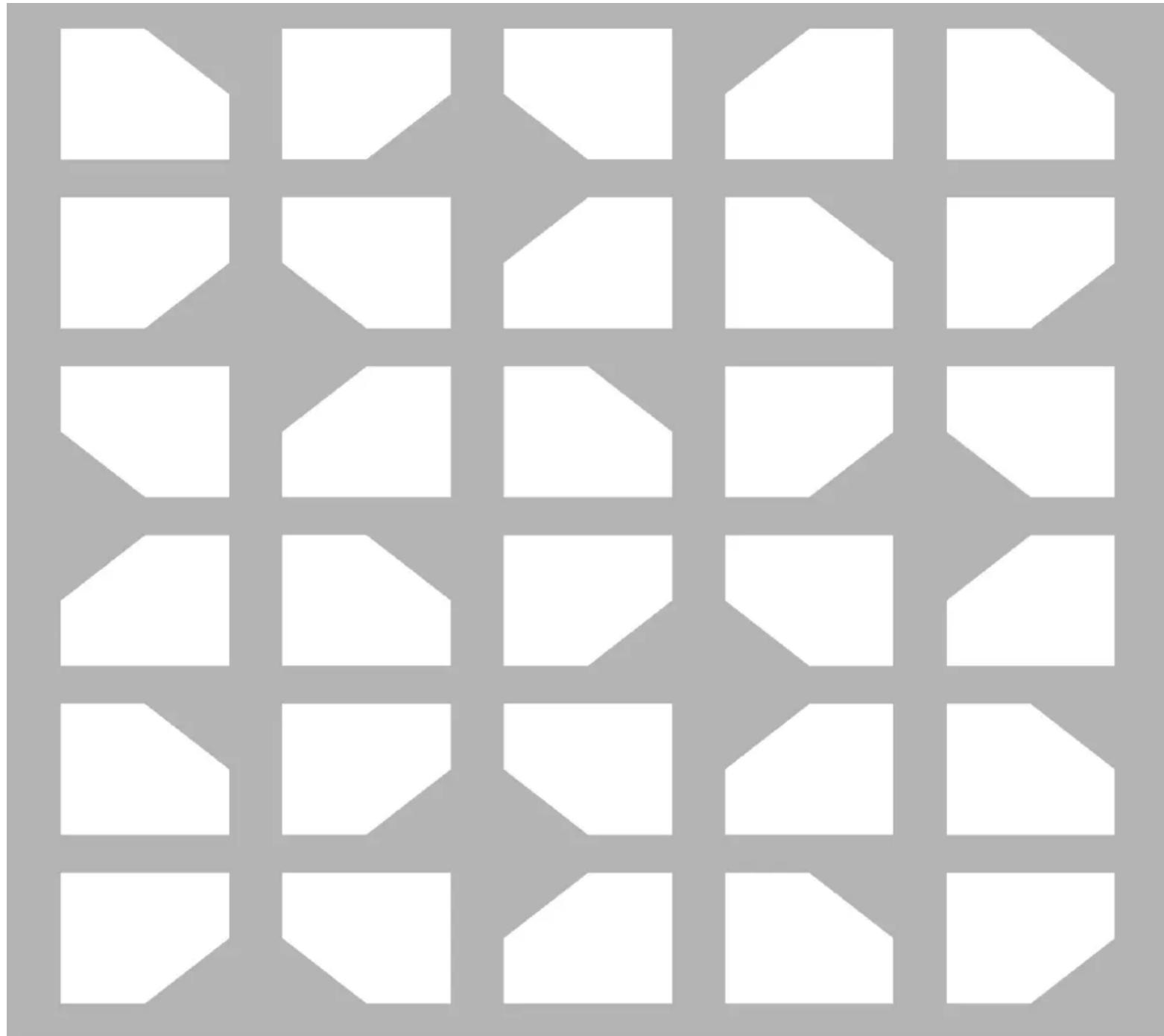
natural_image
Abstract geometric pattern composed of white polygons on a gray background (no text or symbols)
F01U401529
Bosch Sicherheitssysteme GmbH Bosch Security Systems, LLC
Robert-Bosch-Ring 5
85630 Grasbrunn
Germany
www.boschsecurity.com
12000 Portland Avenue South
Burnsville MN 55337
USA
www.electrovoice.com
© Bosch Security Systems,
LLC, 2022
- EVOLVE Wall mount kit
- Safety
- Suspension
- Warning!
- Safety point
- Notices
- Old electrical and electronic appliances
- Copyright and disclaimer
- Short information
- Introduction
- System features
- EVOLVE-WMK-PB / EVOLVE-WMK-PW
- EVOLVE-WMK-NB / EVOLVE-WMK-NW
- EVOLVE-TM-B
- Packing list
- Wiring and installation
- Wiring the EVOLVE column
- EVOLVE-WMK-NB / EVOLVE-WMK-NW / EVOLVE-TM-B
- Refer to
- Attaching the column speaker adapter to the EVOLVE column
- Attaching the EVOLVE column to the wall bracket
- Installing the wall part
- Notice!
- Caution!
- Attaching the handle part to the EVOLVE column
- Mounting the wall bracket
- Attaching the cosmetic cover set
- Attaching the EVOLVE column to the truss mount bracket
- Wiring the subwoofer
- Installing the subwoofer amplifier input cover
- Technical data
- Additional pin-out tables
- Dimensions
- Bosch Sicherheitssysteme GmbH Bosch Security Systems, LLC
Brand : ELECTRO-VOICE
Model : EVOLVE-WMK-NB
Category : Uncategorized