
GLA-PWS50 - Power Supply Crestron - Free user manual and instructions
Find the device manual for free GLA-PWS50 Crestron in PDF.


| Product Type | 50 Watt Cresnet Power Supply |
| Brand | Crestron |
| Model | GLA-PWS50 |
| Dimensions (H x W x D) | 4.00 in x 5.55 in x 2.27 in (10.16 cm x 14.09 cm x 5.76 cm) |
| Weight | 1.2 lbs (0.54 kg) |
| Input Voltage | 100-240 VAC, 50/60 Hz |
| Input Current | 1.0 A |
| Output Voltage | 24 VDC |
| Output Current | 2.1 A |
| Output Power | 50 Watts |
| Ripple/Noise | < 1% |
| Mounting | Over 4" square or 2-gang electrical box |
| Enclosure Material | Metal |
| Operating Temperature | 32° to 104°F (0° to 40°C) |
| Humidity | 10% to 90% RH (non-condensing) |
| Heat Dissipation | 26 BTU/Hr |
| Fuse Type | 5 x 20 mm, 3.15 A, Time Lag, Ceramic Cartridge |
| Indicators | Green LED for 24 VDC output |
| Wiring | Flying leads: Line (black, white, green/yellow), Output (red, black/white) |
| Compliance | UL Listed, CE, FCC Class B |
| Safety Note | Use 75°C copper wire; overcurrent protection 15-20 A |
Frequently Asked Questions - GLA-PWS50 Crestron
User questions about GLA-PWS50 Crestron
0 question about this device. Answer the ones you know or ask your own.
Ask a new question about this device
Download the instructions for your Power Supply in PDF format for free! Find your manual GLA-PWS50 - Crestron and take your electronic device back in hand. On this page are published all the documents necessary for the use of your device. GLA-PWS50 by Crestron.
USER MANUAL GLA-PWS50 Crestron
The GLA-PWS50 is a 50 Watt Cresnet ^® Power Supply designed for use with a Crestron ^® Green Light ^™ system, or anywhere a wall-mountable Cresnet power supply is needed. The GLA-PWS50 mounts conveniently over a 4" square or 2-gang electrical box. All connections are made inside the electrical box via flying leads using twist-on wire connectors. A partition is included to isolate high voltage from Class 2 wiring within the box.
• 50 Watt Cresnet power supply
- Powers the IPAC and other Cresnet devices
- Provides backup power for Crestron Green Light cabinets
- Mounts to a 4" square or 2-gang electrical box
GLA-PWS50 Physical View
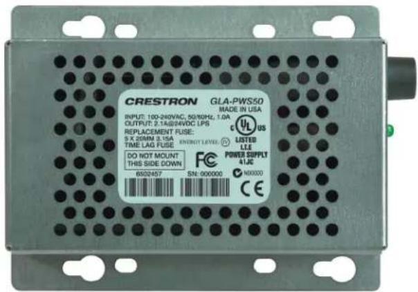
Specifications
GLA-PWS50 Specifications
| SPECIFICATION | DETAILS |
| Output PowerOutput PowerRipple/Noise | 50 Watts (2.1 Amps) @ 24 Volts DC, regulated, limited power source<1% |
| Power RequirementsInput | 1.0 Amp @ 100-240 Volts AC, 50/60 Hz |
| Enclosure Metal construction, mounts to a 4-inch square or 2-gang electrical box, includes low-voltage partition | |
| EnvironmentalTemperatureHumidityHeat Dissipation | 32° to 104°F (0° to 40°C)10% to 90% RH(non-condensing)26 BTU/Hr |
| DimensionsHeightWidthDepth | 4.00 in (10.16 cm)5.55 in (14.09 cm)2.27 in (5.76 cm) |
| Weight 1.2 lbs (0.54 kg) | |
Industry Compliance
This product is Listed to applicable UL Standards and requirements by Underwriters Laboratories Inc.

(E324810)
As of the date of manufacture, the GLA-PWS50 has been tested and found to comply with specifications for CE marking.

NOTE: This device complies with part 15 of the FCC rules. Operation is subject to the following two conditions: (1) this device may not cause harmful interference and (2) this device must accept any interference received, including interference that may cause undesired operation.
This equipment has been tested and found to comply with the limits for a Class B digital device, pursuant to part 15 of the FCC Rules. These limits are designed to provide reasonable protection against harmful interference in a residential installation. This equipment generates, uses and can radiate radio frequency energy and if not installed and used in accordance with the instructions, may cause harmful interference to radio communications. However, there is no guarantee that interference will not occur in a particular installation. If this equipment does cause harmful interference to radio or television reception, which can be determined by turning the equipment off and on, the user is encouraged to try to correct the interference by one or more of the following measures:
■ Reorient or relocate the receiving antenna.
- Increase the separation between the equipment and receiver.
- Connect the equipment into an outlet on a circuit different from that to which the receiver is connected.
- Consult the dealer or an experienced radio/TV technician for help.
Application
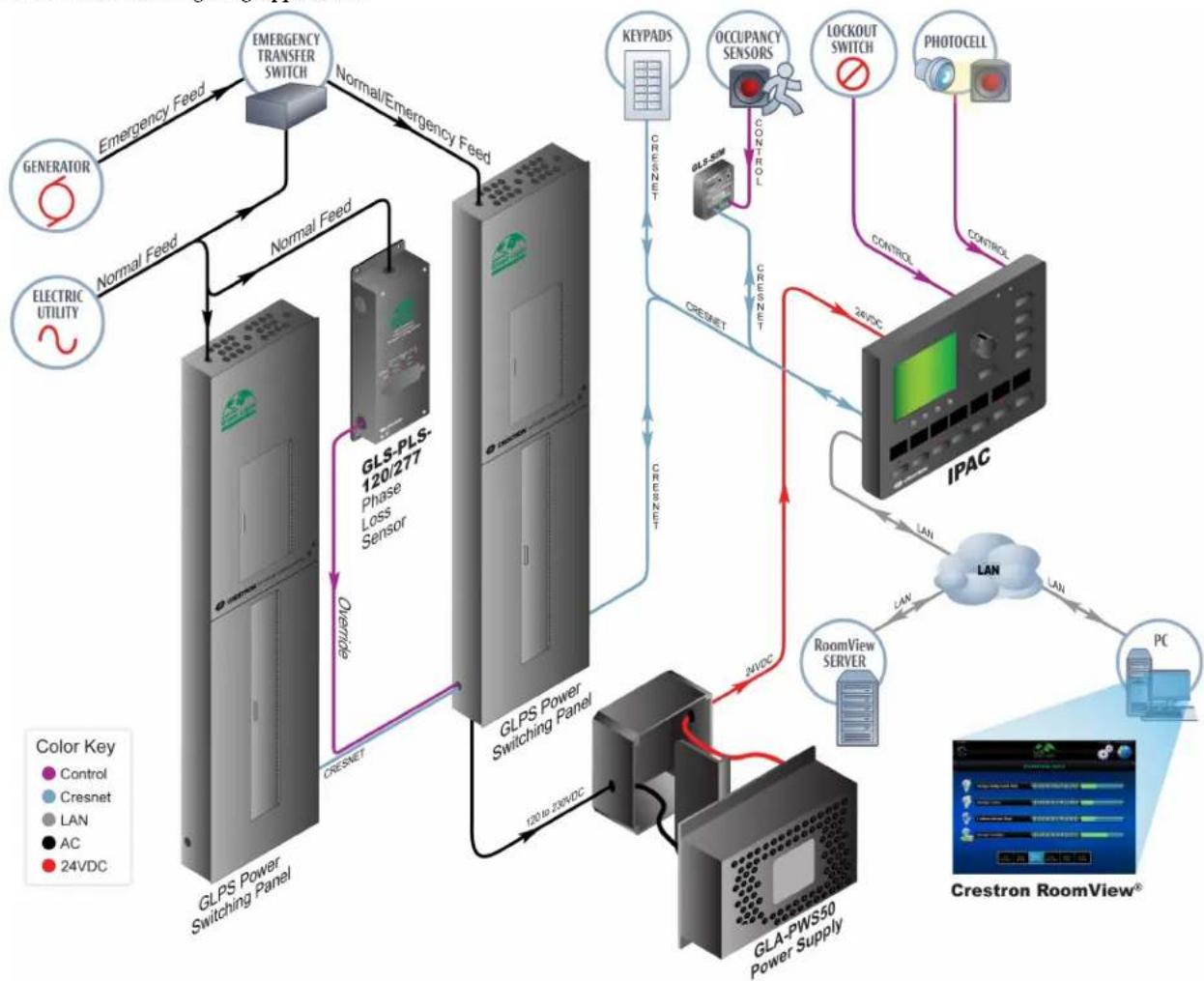
The following diagram shows a GLA-PWS50 module in a typical application.
GLA-PWS50 in a Lighting Application
flowchart
graph TD
    A["GENERATOR"] -->|Emergency Feed| B["EMERGENCY TRANSFER SWITCH"]
    B -->|Normal/Emergency Feed| C["GLPS Power Switching Panel"]
    C -->|Normal Feed| D["GLS-PLS-120/277 Phase Loss Sensor"]
    D -->|Overwrite| E["GLPS Power Switching Panel"]
    E -->|CRESNET| F["CREST"]
    F -->|CRESNET| G["IPAC"]
    G -->|CONTROL| H["CHAFT"]
    H --> I["LAN"]
    I --> J["PC"]
    J --> K["Crestron RoomView®"]
    style A fill:#f9f,stroke:#333
    style B fill:#ccf,stroke:#333
    style C fill:#cfc,stroke:#333
    style D fill:#fcc,stroke:#333
    style E fill:#cff,stroke:#333
    style F fill:#ffc,stroke:#333
    style G fill:#fcf,stroke:#333
    style H fill:#cff,stroke:#333
    style I fill:#ffc,stroke:#333
    style J fill:#cfc,stroke:#333
    style K fill:#fcc,stroke:#333
Physical Description
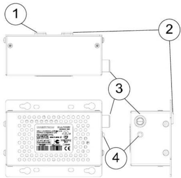
This section provides information on the connections, controls and indicators available on the GLA-PWS50.
GLA-PWS50 Overall Dimensions

GLA-PWS50
Connectors, Controls & Indicators
| # | CONNECTORS, CONTROLS & INDICATORS | DESCRIPTION |
| 1 | LINE POWER (3) 6" flying leads, 18 AWG, line power inputHot (black), neutral (white), and ground (green/yellow) connections | |
| 2 | OUTPUT (2) 6" flying leads, 18 AWG,Cresnet power output+24 VDC (red), G (black/white) connectionsConnects to "24" and "G"connections of the Cresnet control network, or directly to a 24 Volt DC powered Crestron device | |
| 3 | FUSE DC output fuse, T3.15AH(5x20mm, 250V, 3.15A, time-lag, ceramic cartridge). | |
| 4 | 24VDC LED | (1) green LED, indicates 24 Volts DC output, extinguishes when fuse is blown |
Setup
Important Notes
Read before installation.
- Permits: An electrical permit shall be obtained prior to each installation.
- Codes: Install in accordance with all local and national electrical codes.
- Wiring: Use 75^ copper wire only.
- Disconnect device: An appropriate and readily accessible disconnect device shall be provided as part of the building installation wiring.
- To ensure adequate branch circuit protection, use an overcurrent protective device rated 15 or 20 amps.
• Not suitable for Hazardous/Classified areas.
Supplied Hardware
The hardware supplied with the GLA-PWS50 is listed in the following table.
Supplied Hardware for the GLA-PWS50
| DESCRIPTION | PART | NUMBER |
| Partition | 2022663 | |
| Plastic Rivet 2005423 3 | ||
| Twist-On Wire Connector 2005432 5 |
QUANTITY 1
Assembly
The GLA-PWS50 comes with a partition to isolate high voltage from Class 2 wiring when installed in an electrical box. Refer to the following diagram when mounting the partition on the GLA-PWS50.
Install the Partition

Hardware Hookup
WARNING: RISK OF SERIOUS PERSONAL
INJURY. Turn off power at the circuit breaker(s) prior to installation. Installing with power on can result in serious personal injury and damage to the device.
- Use two twist-on wire connectors to secure the Class 2 wiring to the Cresnet network as shown in the following diagram.
Connect Class 2 Wiring (Partition and High Voltage Wiring Removed for Clarity)

- Use three twist-on wire connectors on the line input wires to connect to the line power as shown in the following diagram.
Connect High Voltage Wiring (Partition and Class 2 Wiring Removed for Clarity)

Installation
The GLA-PWS50 mounts over a 4" square or 2-gang electrical box. Refer to the following diagram when installing the GLA-PWS50.
NOTE: Ensure that the wires will not be pinched during the installation process by pushing the wires into the electrical box.
Install GLA-PWS50 (Wires Removed for Clarity)

NOTE: The GLA-PWS50 should never be installed with the label facing down.
- To ensure proper ventilation, do not cover the ventilation holes on the front of the unit.
- Turn on the circuit breaker after completing installation. The green LED will illuminate
Fuse Replacement
If the GLA-PWS50 does not power up when it is connected to line power, the fuse may need to be replaced. The fuse holder is located on the right side of the power supply (next to the LED). To replace the fuse:
- Disconnect power to the GLA-PWS50.
- Use a flat-head screwdriver to push in the fuse holder.
- While pushing in the fuse holder, turn screwdriver counterclockwise until the fuse holder pops out.
- Remove the fuse from the fuse holder and insert a new fuse.
FUSE TYPE: 5 x 20mm 3.15A Time Lag
CAUTION: Only use the specified type of fuse when replacing a blown fuse. Failure to do so may cause damage to the GLA-PWS50.
- Insert the fuse holder into the GLA-PWS50.
- Push in the fuse holder with a flat head screwdriver. While pushing in the fuse holder, turn the screwdriver clockwise until the fuse holder sinks in.
- Push in the fuse holder a little further and turn the screwdriver clockwise until the fuse holder locks in place.
- Connect power to the GLA-PWS50.
Problem Solving
Troubleshooting
The following table provides corrective action for possible trouble situations. If further assistance is required, please contact a Crestron customer service representative.
GLA-PWS50 Troubleshooting
| TROUBLE POSSIBLE CAUSE(S) | CORRECTIVE ACTION | |
| LED does not turn on. | Circuit breaker is off. | Verify that circuit breaker is on. |
| Fuse is blown. Check fuse and replace if necessary. | ||
| GLA-PWS50 is not properly connected. | Verify wiring. | |
Further Inquiries
If you cannot locate specific information or have questions after reviewing this guide, please take advantage of Crestron's award winning customer service team by calling Crestron at 1-888-CRESTRON [1-888-273-7876].
You can also log onto the online help section of the Crestron website (www.crestron.com/onlinehelp) to ask questions about Crestron products. First-time users will need to establish a user account to fully benefit from all available features.
Return and Warranty Policies
Merchandise Returns / Repair Service
- No merchandise may be returned for credit, exchange or service without prior authorization from CRESTRON. To obtain warranty service for CRESTRON products, contact an authorized CRESTRON dealer. Only authorized CRESTRON dealers may contact the factory and request an RMA (Return Merchandise Authorization) number. Enclose a note specifying the nature of the problem, name and phone number of contact person, RMA number and return address.
- Products may be returned for credit, exchange or service with a CRESTRON Return Merchandise Authorization (RMA) number. Authorized returns must be shipped freight prepaid to CRESTRON, 6 Volvo Drive, Rockleigh, N.J. or its authorized subsidiaries, with RMA number clearly marked on the outside of all cartons. Shipments arriving freight collect or without an RMA number shall be subject to refusal. CRESTRON reserves the right in its sole and absolute discretion to charge a 15% restocking fee plus shipping costs on any products returned with an RMA.
- Return freight charges following repair of items under warranty shall be paid by CRESTRON, shipping by standard ground carrier. In the event repairs are found to be non-warranty, return freight costs shall be paid by the purchaser.
CRESTRON Limited Warranty
CRESTRON ELECTRONICS, Inc. warrants its products to be free from manufacturing defects in materials and workmanship under normal use for a period of three (3) years from the date of purchase from CRESTRON, with the following exceptions: disk drives and any other moving or rotating mechanical parts, pan/tilt heads and power supplies are covered for a period of one (1) year; touchscreen display and overlay components are covered for 90 days; batteries and incandescent lamps are not covered.
This warranty extends to products purchased directly from CRESTRON or an authorized CRESTRON dealer. Purchasers should inquire of the dealer regarding the nature and extent of the dealer's warranty, if any.
CRESTRON shall not be liable to honor the terms of this warranty if the product has been used in any application other than that for which it was intended or if it has been subjected to misuse, accidental damage, modification or improper installation procedures. Furthermore, this warranty does not cover any product that has had the serial number altered, defaced or removed.
This warranty shall be the sole and exclusive remedy to the original purchaser. In no event shall CRESTRON be liable for incidental or consequential damages of any kind (property or economic damages inclusive) arising from the sale or use of this equipment. CRESTRON is not liable for any claim made by a third party or made by the purchaser for a third party.
CRESTRON shall, at its option, repair or replace any product found defective, without charge for parts or labor. Repaired or replaced equipment and parts supplied under this warranty shall be covered only by the unexpired portion of the warranty.
Except as expressly set forth in this warranty, CRESTRON makes no other warranties, expressed or implied, nor authorizes any other party to offer any warranty, including any implied warranties of merchantability or fitness for a particular purpose. Any implied warranties that may be imposed by law are limited to the terms of this limited warranty. This warranty statement supersedes all previous warranties.
Trademark Information
All brand names, product names and trademarks are the sole property of their respective
owners. Windows is a registered trademark of Microsoft Corporation.
Windows95/98/Me/XP/Vista and WindowsNT/2000 are trademarks of Microsoft Corporation.



- Specifications
- Industry Compliance
- Application
- Physical Description
- Setup
- Important Notes
- Supplied Hardware
- Assembly
- Hardware Hookup
- WARNING: RISK OF SERIOUS PERSONAL
- Installation
- Fuse Replacement
- Problem Solving
- Troubleshooting
- Further Inquiries
- Return and Warranty Policies
- Merchandise Returns / Repair Service
- CRESTRON Limited Warranty
- Trademark Information
Brand : Crestron
Model : GLA-PWS50
Category : Power Supply