Cloudplate T7 - Uncategorized AC Infinity - Free user manual and instructions
Find the device manual for free Cloudplate T7 AC Infinity in PDF.


| Brand | AC Infinity |
| Model | Cloudplate T7 (AI-CP2L) |
| Product Type | Rack Mount Cooling System (Fan Unit) |
| Frame Material | Aluminum with brushed black finish |
| Motor Type | PWM-controlled, quiet, energy-efficient DC motor |
| Bearing Type | Dual ball bearings (rated 67,000 hours) |
| Controller | Built-in LCD display with temperature monitoring, thermal control, speed control, alarms, and SMART energy mode |
| Operating Modes | AUTO, SMART, SPEED, ALARM, BUFFER |
| Fan Speed Levels | 6 levels |
| Temperature Sensor | Corded precision stainless steel thermal probe |
| Temperature Scale | Fahrenheit or Celsius (toggle via leaf button) |
| Alarm | Adjustable temperature alarm with audible beep; can be disabled |
| Expansion Port | DC connector port for daisy-chaining additional fans or rack roof fan kit |
| Display Features | Adjustable brightness, eco-display (turn off display), lock function |
| Mounting | Fits standard 19-inch racks; includes mounting screws; cage nuts may be required for some rails |
| Power Supply | AC/DC power adapter (input: 100-240V AC; output: 12V DC, 1A typical) |
| Warranty | 2 years from date of purchase |
| Included Accessories | Cooling fan system, thermal probe, mounting screws (4), zip ties, power adapter |
| Alert Icons | Fan failure, alarm, and display lock indicators on LCD |
| Maintenance | Clean with a dry cloth; do not use liquid cleaners or immerse in water |
| Repairability | Contact AC Infinity for fan replacement or other service; warranty covers defects |
Frequently Asked Questions - Cloudplate T7 AC Infinity
User questions about Cloudplate T7 AC Infinity
0 question about this device. Answer the ones you know or ask your own.
Ask a new question about this device
Download the instructions for your Uncategorized in PDF format for free! Find your manual Cloudplate T7 - AC Infinity and take your electronic device back in hand. On this page are published all the documents necessary for the use of your device. Cloudplate T7 by AC Infinity.
USER MANUAL Cloudplate T7 AC Infinity
RACK MOUNT COOLING SYSTEM
USER MANUAL
WELCOME
Thank you for choosing AC Infinity. We are committed to product quality and friendly customer service. If you have any questions or suggestions, please don't hesitate to contact us. Visit www.acinfinity.com and click contact for our contact information.
support@acinfinity.com
WEB
www.acinfinity.com
LOCATION
Los Angeles, CA
MANUAL CODE CP1704X1
PRODUCT
CONTROLLER 12
CLOUDPLATE T1
CLOUDPLATE T1-N
CLOUDPLATE T2
CLOUDPLATE T5
CLOUDPLATE T6
CLOUDPLATE T7
CLOUDPLATE T7-N
CLOUDPLATE T9
CLOUDPLATE T9-N
CLOUDPLATE T12
RACK ROOF FAN
MODEL
AI-CTB12
AI-CPT1
AI-CPT1-N
AI-CPT2
AI-CPT5
AI-CPT6
AI-CP2L
AI-CP2H
AI-CPT9
AI-CPT9-N
AI-CPT12
AI-RRF7
UPC-A
819137020047
854759004976
854759004983
854759004990
819137020009
819137020016
854759004501
854759004518
819137020023
819137020030
819137020054
819137020061
MANUAL INDEX
Company Contact Page 3
Manual Index Page 5
Rack Cooling Guide Page 6
Key Features Page 7
Product Contents ...... Page 8
Installation Page 9
Programming Page 12
Connecting More Fans Page 19
Other AC Infinity Products Page 20
Warranty Page 21
RACK COOLING GUIDE
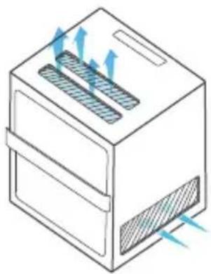
ACCESS TO OUTSIDE AIRFLOW
For the fan system to work properly, the rack fan must have access to outside air. It can be ventilation holes on the rack or on the cabinet if it's holding an open frame rack. The holes allow the rack fan to exhaust warm air and intake cool air.
natural_image
Diagram of a rectangular device with heat exchanger and ventilation slots, showing airflow direction (no text or symbols)INTAKE AND EXHAUST
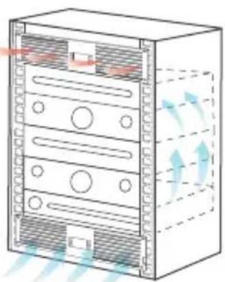
All rack fan systems should contain an intake and exhaust variable. To assist with natural convection, position fans near the top of the rack configured to exhaust out the warm air and fans near the bottom to push in cool air.
natural_image
Diagram of a server rack with heat exchanger and ventilation arrows (no text or labels)OPTIMIZING AIRFLOW
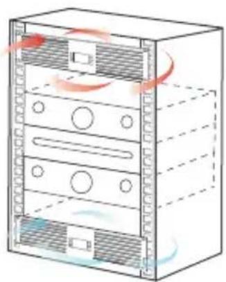
To optimize airflow circulation, we recommend using blank panels to fill the empty spaces on the rack. This increases the efficiency of the fan systems by preventing warm air from escaping midway and being recycled back into the rack.
natural_image
Diagram of a server rack with ventilation ducts and fan slots (no text or symbols)KEY FEATURES
ALUMINIUM FRAME
Features an aluminium frame with a brushed black finish and CNC machined corners give cabinets a clean look.
QUIET PWM MOTOR
PWM-controlled motor features precise speed control, reduced rotor noise, and runs on energy efficient DC voltage.
SMART CONTROLLER
LCD display enables temp monitoring, thermal control, speed control, alarms, and SMART energy mode.


natural_image
Front view of a four-framed industrial fan with heat sinks and mounting holes (no text or symbols visible)DUAL BALL BEARINGS
Fans contain long-life ball bearings rated at 67,000 hours. Also enables fans to be mounted in any direction.
THERMAL PROBE
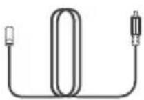
The corded precision sensor probe constructed of stainless steel ensures an accurate temperature reading.
EXPANSION PORTS
Each unit contains a DC connector port which can be used to control another rack fan unit or rack roof fan kit.
PRODUCT CONTENTS
CLOUDPLATE T1 AI-CPT1
CLOUDPLATE T1-N AI-CPT1-N
CLOUDPLATE T2 AI-CPT2
CLOUDPLATE T5 AI-CPT5
CLOUDPLATE T6 AI-CPT6
CLOUDPLATE T7 AI-CP2L
CLOUDPLATE T7-N AI-CP2H
CLOUDPLATE T9 AI-CPT9
CLOUDPLATE T9-N AI-CPT9-N

natural_image
Front panel of a server rack with ventilation grilles and AC INFINITY indicator (no text or symbols on the diagram itself)Cooling Fan System (1)
THERMAL PROBE (1)
natural_image
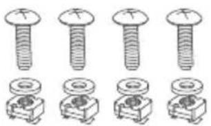
Illustration of five different types of bolts and nuts, including screws, bolts, and bolts (no text or symbols present)MOUNTING SCREWS (4)
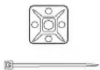
ZIP TIES (1)
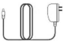
POWER ADAPTER (1)
RACK ROOF FANS AI-RRF7 Roof Fans + Screws + Power Adapter
CONTROLLER 12 AI-CTB12 Controller + Probe + Screws + Power Adapter
CLOUDPLATE T12 AI-CPT12 Controller + Probe + Roof Fans + Screws + Adapter
INSTALLATION
STEP 1
Determine the position you wish to mount the rack fan unit onto your rack. Please refer to page 6 for a guide on the best fan placement to optimize cooling.
STEP 2
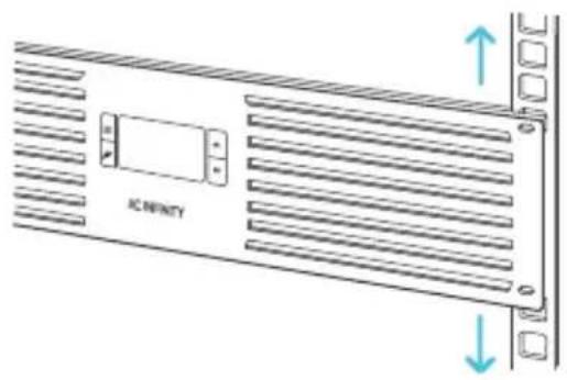
Use a screwdriver and the included screws to secure the fan unit onto your rack. Depending on the rack rail type, you may need to install cage nuts first. Please note that some rack rails may come pre-threaded with another screw size.
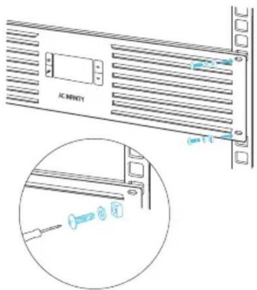
INSTALLATION
STEP 3
Check the included AC power adapter to make sure the power rating is compatible with your outlet. Plug the DC connector of the AC power adapter into the port labeled "POWER" on the backside of the rack fan unit.
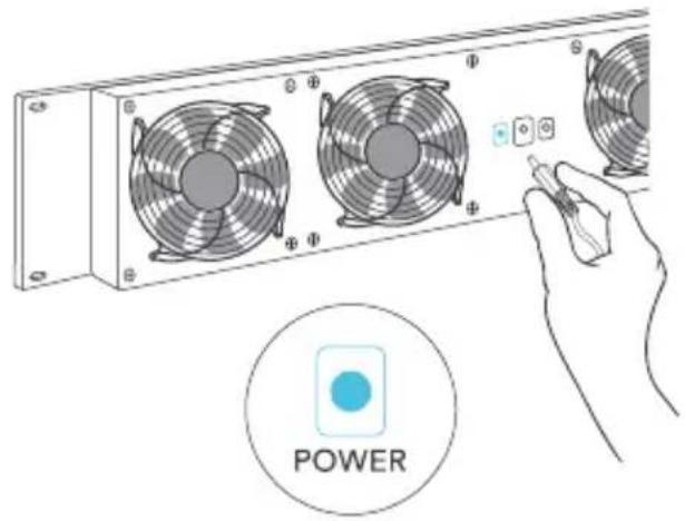
natural_image
Illustration of a server rack with multiple fans and a hand adjusting a button, labeled 'POWER' (no text on fan or button)STEP 4
Plug the AC power adapter into a standard power outlet. Please check that the LCD screen is now displaying all contents and that the settings can be changed. The probe's temperature readings will not yet be visible.

natural_image
Hand holding a small electronic device with a cartoon face on top, no visible text or symbolsINSTALLATION
STEP 5
Plug the male connector of the thermal probe into the port labeled "PROBE" on the backside of the rack fan unit. Please check that the LCD screen now displays the probe's temperature readings.
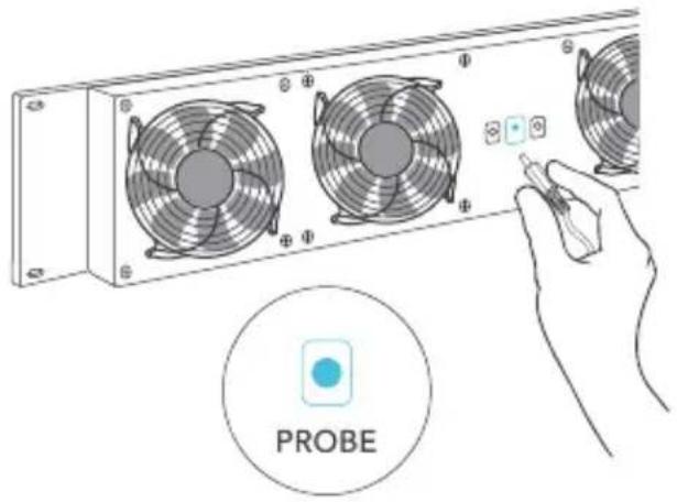
STEP 6
Secure the head of the probe onto the rack using the included cable ties. We recommend positioning the probe near your hottest equipment and away from any fans that can distort the probe's temperature readings.
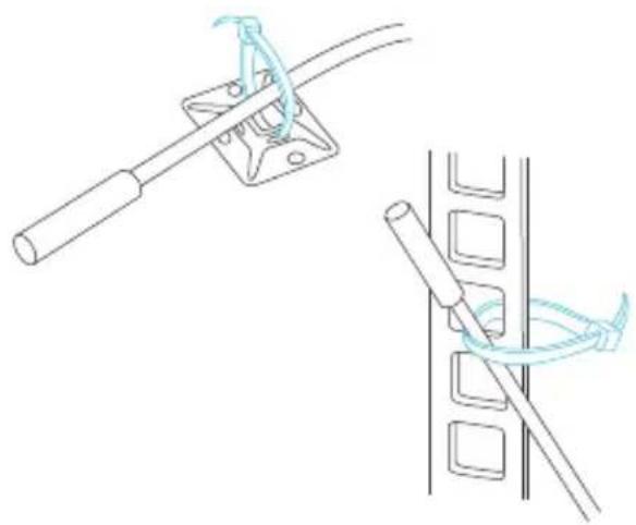
natural_image
Technical line drawing showing two mechanical assembly steps: one with a lever and cable, the other with a coiled rod (no text or symbols)PROGRAMMING
CONTROLLER 12, CLOUDPLATE T1, CLOUDPLATE T1-N CLOUDPLATE T2, CLOUDPLATE T5, CLOUDPLATE T6 CLOUDPLATE T12
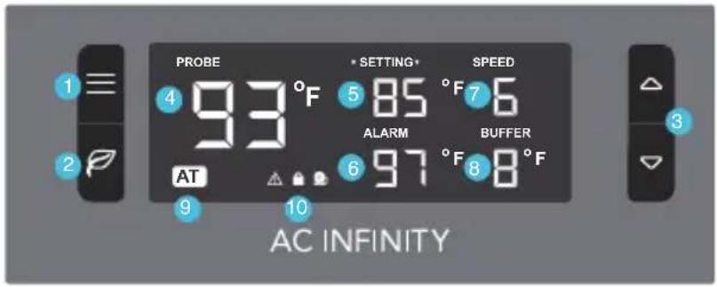
CLOUDPLATE T7, CLOUDPLATE T7-N
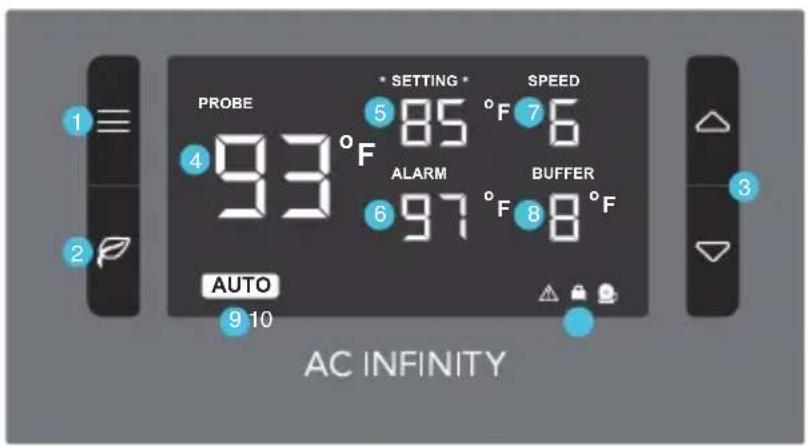
CLOUDPLATE T9, CLOUDPLATE T9-N
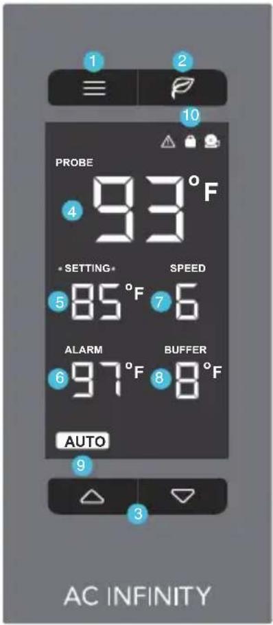
PROGRAMMING
1. MODE BUTTON
Cycles through the modes: AUTO, SMART, SPEED, ALARM, BUFFER. Holding for three seconds will lock or unlock the display.
2. LEAF BUTTON
This turns the display off while programs run in the background. Holding will change degrees to Fahrenheit or Celsius.
3. UP / DOWN BUTTON
The up and down buttons adjusts the settings of the mode that you are in. Up button increases and down button decreases.
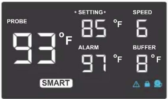
4. PROBE TEMP.
Actively shows the current temperature that the corded thermal probe is measuring. Will show “- -” if no probe is plugged in.
5. SETTING TEMP.
Shows the temperature you have set for the fan system to trigger in AUTO and SMART Mode, which share the same set temp.
6. ALARM TEMP.
Shows the temperature that you set the fan's alarm system to trigger. Please see page 16 for more information.
7. FAN SPEED
The settings for the max speed the fans can reach. Shows what speed the fans are currently running at. Six speeds are available.
8. BUFFER
The buffer range settings of AUTO and SMART Mode programming. Please see pages 15 for more information.
9. MODE
Shows what Mode the controller is in: AUTO, SMART, SPEED, ALARM, or BUFFER. Please see pages 14 -16 for more info.
10. ALERT ICONS
The icons on the display represents fan failure, alarm, and display lock. The icons will flash and may emit an audible beep when triggered.
PROGRAMMING
QUICK START
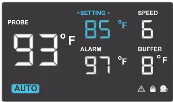
Press the MODE button until you are on AUTO mode. This mode works like a thermostat. Press the up and down triangle buttons to change the SETTING temperature on the screen. The PROBE temperature is what the thermal probe is measuring. When the PROBE temperature exceeds the SETTING temperature, the fans will start running.
SPEED SETTING
In this mode, the fans will run non-stop regardless of temperature. Pressing the up and down buttons in this mode will change the speed of the fan. Which ever speed is designated in this mode will also be the speed used in AUTO Mode and the max speed of the fans in SMART Mode.
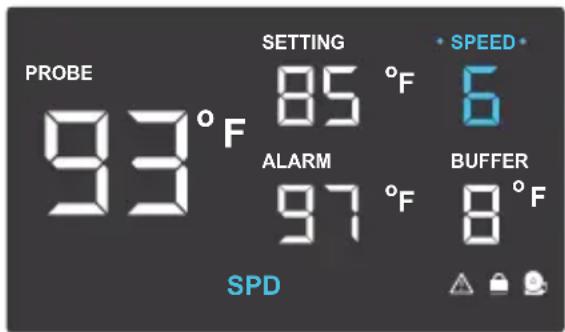
AUTO MODE
This is the thermostat setting where the fans will start running when the PROBE temperature reaches or surpasses the SETTING temperature. The SETTING temperature can be designated by pressing the up and down buttons while in this mode. Once the fans start running, the PROBE temperature will need to fall at least 2^ F below the SETTING temp for the fans to stop running. This variation buffer can be changed. Please see page 15 for more information.
PROGRAMMING
BUFFER SETTING
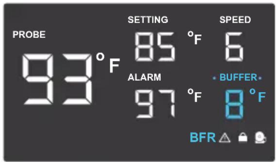
In AUTO mode, a buffer is built in to prevent your fan from turning on and off too quickly due to small variations in the environment. In SMART mode, there is a range of temperatures between each speed. You can increase or decrease this buffer or range by pressing the up and down buttons.
SMART MODE
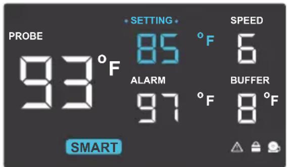
This is the energy saving mode where the fans will change speed depending on the temperature. The SETTING temperature can be designated by pressing the up and down triangle buttons while in this mode.
For every 2^ F increment that the PROBE temperature is below the SETTING temperature, the speed of the fans will decrease by one level. This increment can be changed to 4^ F, 6^ F, or 8^ F by adjusting the Buffer Setting instructed above.
The fan speed you designated in ON Mode will also be the max speed the fan's can reach. This occurs when the PROBE temperature reaches or exceeds the SETTING temperature.
PROGRAMMING
ALARM SETTING
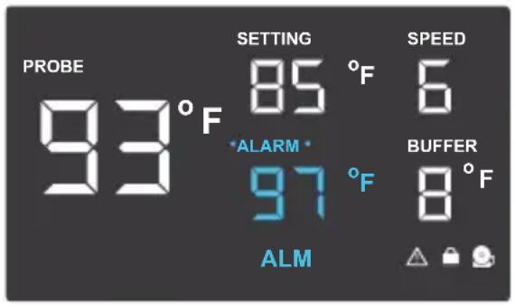
In this mode, you can set what temperature the system's alarm will trigger by pressing the up and down triangle buttons. When the PROBE temperature reaches or exceeds the ALARM temperature, the alarm will activate. The alarm will only activate while the controller is in ON, AUTO, or SMART Mode so please remember to exit ALARM Mode once the alarm has been set. When the alarm is triggered, the fan's will run at max speed regardless of the setting and will make an audible beep every three seconds. This will keep occurring until the temperature drops below the ALARM temp. or if any buttons are pressed. The alarm can be disabled by pressing the up triangle button until the temperature is at 140° F, then pressing the up button once more to show "OF".
PROGRAMMING
The temperatures displayed can be set to Fahrenheit or Celsius scale by holding the LEAF button until °F or °C is shown after the digits. All digits displayed will be automatically converted to the designated scale.
DISPLAY BRIGHTNESS
To adjust the brightness of the display, hold down the MODE button while pressing the up button repeatedly to increase the brightness. Hold down the MODE button while pressing the down button repeatedly to decrease the brightness. There are three brightness settings available.
CONTROLLER LOCK
Holding the MODE button for three or more seconds will lock the controller. The controller will still work as programmed; however, pressing any buttons will not have an effect and will cause the screen lock icon to flash and will make an audible beep three times a second. This option was designed to prevent your controller settings from being changed by accident. Holding the MODE button again for three or more seconds will unlock the controller.
ECO-DISPLAY
To conserve energy, you can choose to set the display into Eco Mode by pressing the button with a leaf on it to turn the display off. All programs will be operating in the background and fans will still be triggered to run according to the settings. Press any button will turn the display back on.
PROGRAMMING
ALERT ICONS
On the bottom right of the display there are three alert icons. They are visible to show that the system's functions are being monitored. They will flash when the controller wishes to alert you that a particular function is being triggered.
FAN FAILURE ALERT
The fan failure icon will flash when one or more fans in the CLOUDPLATE cooling system fails. Please see page 21 for contact information regarding fan replacement and exchanges.
DISPLAY LOCK ALERT
This icon is not visible when the controller is unlocked. The icon will flash when any buttons are pressed while the controller is locked. Please see page 17 for more information.
ALARM ALERT
The alarm alert icon will flash when the probe temperature reaches or exceeds the alarm temperature you have set. Please see page 16 for more information on setting up the alarm.

natural_image
Three blue circular icons with warning symbols: triangle, lock, and megaphone (no text or labels)EXTENSION FAN UNITS
CLOUDPLATE SERIES
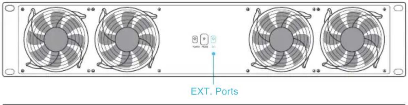
To add more cooling and ventilation to your rack, you can plug in additional fans such as the RACK ROOF FAN into a CLOUDPLATE Series unit. There is a port on the backside marked "EXT." which allows the unit to support additional fans. You can also connect one CLOUDPLATE unit to another to share the same settings; a daisy chain cord is required. The connected CLOUDPLATE unit must be set to SPEED Settings Mode, it's speed set to max, and the alarm turned off. Connected fans will share the same temperature control settings.
CONTROLLER 12
The Controller 12 can also control CLOUDPLATE Series fan units and RACK ROOF FANS in the exact same way as described above. In addition, it can also control AIRPLATE Series cabinet fans and MULTIFAN Series component USB fans. On the backside, plug USB fans into ports marked "5V DC" to share the same temperature settings. Connected USB fans must have their speed set to max if they feature an inline speed controller.

AC INFINITY PRODUCTS
AIRCOM SERIES
The AIRCOM component fan system cools receivers, amplifiers, and other AV components. S-Series models features a thermal trigger and speed control. T-Series features a LCD digital display with thermal and speed control, alarm alerts, failure triggers, and backup memory.

PRODUCT
| AIRCOM S6 | AI-ACS6 | 11.6 x 6.3 x 1.5 in. |
| AIRCOM S7 | AI-ACS7 | 11.6 x 6.3 x 1.5 in. |
| AIRCOM S8 | AI-ACS8 | 17 x 13.5 x 1.5 in. |
| AIRCOM S9 | AI-ACS9 | 17 x 13.5 x 1.5 in. |
| AIRCOM T8 | AI-ACT8 | 17 x 13.5 x 1.5 in. |
| AIRCOM T9 | AI-ACT9 | 17 x 13.5 x 1.5 in. |
AIRPLATE SERIES
The AIRPLATE series is designed to cool home theater and audio video cabinets. The fans can be powered by USB port or power outlet. Includes an inline speed controller and Boost Speed Adapter. The fans can also be temperature controlled with an Advance Thermal Controller (sold separately).
PRODUCT
| AIRPLATE S1 | AI-CFS80BA | 4.6 x 4.6 x 1.3 in. |
| AIRPLATE S3 | AI-CFS120BA | 6.3 x 6.3 x 1.3 in. |
| AIRPLATE S5 | AI-CFD80BA | 8.4 x 4.4 x 1.3 in. |
| AIRPLATE S7 | AI-CFD120BA | 11.7 x 6.1 x 1.3 in. |
| AIRPLATE S9 | AI-APS9 | 17.5 x 6.1 x 1.3 in |
natural_image
Circular perforated panel with four corner holes, no text or symbols presentWARRANTY
This warranty program is our commitment to you, the original purchaser, that each product sold by AC Infinity will be free from defects in manufacturing for a period of two years from the date of purchase. If a product is found to have a defect in material or workmanship, we will take the appropriate actions defined in this warranty to resolve any issues.
The warranty program applies to any order, purchase, receipt, or use of any products from AC Infinity. The program covers products that have become defective, malfunctioned, or expressively if the product becomes unusable. The warranty program goes into effect on the date of purchase. The program will expire two years from the date of purchase. If your product becomes defective during that period, AC Infinity will replace your product with a new one or issue you a full refund.
The warranty program does not cover abuse or misuse. This includes physical damage, submersion of the product in water, incorrect installation such as wrong voltage input and misuse for any reason other than intended purposes. AC Infinity is not responsible for consequential loss or incidental damages of any nature caused by the product. We will not warrant damage from normal wear such as scratches and dings.

If you are not 100% satisfied with this product, we will be happy to replace it or issue you a full refund. Please contact us!
COPYRIGHT © 2017 AC INFINITY INC. ALL RIGHTS RESERVED
No part of the materials including graphics or logos available in this booklet may be copied, photocopied, reproduced, translated or reduced to any electronic medium or machine readable form, in whole or in part, without specific permission from AC Infinity Inc.
www.acinfinity.com
- RACK MOUNT COOLING SYSTEM
- WELCOME
- MANUAL CODE CP1704X1
- PRODUCT
- MODEL
- UPC-A
- MANUAL INDEX
- RACK COOLING GUIDE
- ACCESS TO OUTSIDE AIRFLOW
- INTAKE AND EXHAUST
- OPTIMIZING AIRFLOW
- KEY FEATURES
- ALUMINIUM FRAME
- QUIET PWM MOTOR
- SMART CONTROLLER
- DUAL BALL BEARINGS
- THERMAL PROBE
- EXPANSION PORTS
- PRODUCT CONTENTS
- INSTALLATION
- STEP 1
- STEP 2
- STEP 3
- STEP 4
- STEP 5
- STEP 6
- PROGRAMMING
- MODE BUTTON
- LEAF BUTTON
- UP / DOWN BUTTON
- PROBE TEMP.
- SETTING TEMP.
- ALARM TEMP.
- FAN SPEED
- BUFFER
- MODE
- ALERT ICONS
- QUICK START
- SPEED SETTING
- AUTO MODE
- BUFFER SETTING
- SMART MODE
- ALARM SETTING
- DISPLAY BRIGHTNESS
- CONTROLLER LOCK
- ECO-DISPLAY
- ALERT ICONS
- FAN FAILURE ALERT
- DISPLAY LOCK ALERT
- ALARM ALERT
- EXTENSION FAN UNITS
- CLOUDPLATE SERIES
- CONTROLLER 12
- AC INFINITY PRODUCTS
- AIRCOM SERIES
- AIRPLATE SERIES
- WARRANTY
- COPYRIGHT © 2017 AC INFINITY INC. ALL RIGHTS RESERVED
Brand : AC Infinity
Model : Cloudplate T7
Category : Uncategorized