
VT-12040-1 - Uncategorized V-TAC - Free user manual and instructions
Find the device manual for free VT-12040-1 V-TAC in PDF.


| Product Type | Lithium Ion Battery (LiFePO4) for Energy Storage |
| Model | VT-12040-1 |
| Brand | V-TAC |
| Nominal Voltage | 51.2 V |
| Capacity | 200 Ah (Total Capacity) |
| Recommended Charge Current | 90 A |
| Max Charge/Discharge Current | 100 A |
| Charge Temperature Range | 0°C to +55°C (recommended +15°C to +35°C) |
| Discharge Temperature Range | -20°C to +60°C (recommended +15°C to +35°C) |
| Storage Temperature Range | 15°C to 35°C |
| Communication Interfaces | CAN, RS485 (via RJ45 ports), Bluetooth (IOE APP) |
| Max Parallel Units | 15 units |
| BMS Protection | Over-voltage, under-voltage, over-current, short circuit, high/low temperature, battery failure |
| Cycle Life | 3 times longer than standard lead-acid batteries |
| Maintenance | Maintenance-free under normal use; routine visual inspection every 3 months |
| Installation | Indoor use only (IP20); wall-mountable with included brackets; requires qualified personnel |
| Dimensions (H x W x D) | Refer to manual for exact dimensions (Fig. 5-1) |
| Weight | Not specified in manual |
| Safety Certifications | CE, UKCA, RoHS |
| Warranty | 10 years* (conditions apply) |
| Discharge Cut-off Voltage | 43.2 V |
| Float Charge Voltage | 58.4 V |
Frequently Asked Questions - VT-12040-1 V-TAC
User questions about VT-12040-1 V-TAC
0 question about this device. Answer the ones you know or ask your own.
Ask a new question about this device
Download the instructions for your Uncategorized in PDF format for free! Find your manual VT-12040-1 - V-TAC and take your electronic device back in hand. On this page are published all the documents necessary for the use of your device. VT-12040-1 by V-TAC.
USER MANUAL VT-12040-1 V-TAC
WEEE Number: 80133970
INSTRUCTION MANUAL
LITHIUM ION BATTERIES
MODEL SKU
VT-12040-1 11447-1

10 YEAR
WARRANTY*
(as per conditions met
INTRODUCTION
Thank you for selecting and buying V-TAC Product. V-TAC will serve you the best. read these instructions carefully & keep this user manual handy for future reference. have any another query, please contact our dealer or local vendor from whom you purchased the product. They are trained and ready to serve you at the best.

MULTI-LANGUAGE MANUAL QR CODE
Please scan the QR code to access the manual in multiple languages.
2.1 Safety Precautions....3
2.2 Abuse Operation. 3
3 Overview 4
3.1 Product Description. 4
3.1.1 Features. 4
3.1.2 Basic Functions. 3
3.2 Application Scenario....5
4 Application Description. 6
4.1 Parallel Connection Application. 6
4.2 Low-temperature Application. 6
4.3 Low Battery-capacity Storage (SOC≤5%). 6
4.4 Application of Nearing the Ocean. 6
5 Product Introduction. 7
5.1 Dimensions. 7
5.2 Panel Introduction. 8
5.3 Meaning of buzzer and LED light....11
6 Installation. 16
6.1 Precautions for Installation. 16
6.2 Installation Preparation. 16
6.2.1 Tools Preparation. 16
6.3 Packing List....18
6.4 Unpacking and Inspection. 18
6.5 Installation. 19
6.6 Cable Connection. 21
6.6.1 Power Cable Connection. 21
6.6.2 Communication Cable Connection. 22
6.6.3 120Ω Resistor Connection. 23
6.6.4 Grounding Cable Connection. 23
7 Parallel Connection. 24
8 Make Your System Run. 28
9 Shipment & Maintenance & Storage. 30
9.1 Shipment....30
9.2 Maintenance....30
9.2.1 Battery Maintenance Considerations....30
9.2.2 Routine Maintenance....31
9.3 Battery Storage....32
10 Trouble Shooting. 33
11 Warranty 34
12 Abbreviations. 35
13 Screen instructions....36
14 Wireless module (APP)....39
Overview
This user manual mainly introduces product introduction, application
description, installation instructions, power-on instructions, maintenance instructions and provides instructions the VT-12040-1 ESS Series LFP battery pack for technical support engineers, maintenance engineers and users.
Reader
This document is mainly applicable to the following engineers
• Technical Support Engineer
• Installation Personnel
- Maintenance Engineer
Signs
The following signs may appear in this article, and their meanings are as follows.
| Sign | Meaning | Description |
 | Danger | Indicates a hazard with a high level of risk that will cause death or serious injury if not avoided. |
 | Warning | Indicates a hazard with a moderate risk that may cause death or serious injury if not avoided. |
 | Notice | Indicates a hazard with a low level of risk that may cause minor or moderate harm if not avoided. |
 | Explanation | Supplementary explanation of key information in the main text."Explanation" is not safety warning information, and does not involve personal, equipment and environmental damage information. |
 | Warning | This device has an IP20 protection rating, which means it is designed for indoor use only. Do not expose this device to moisture or outdoor conditions, as it may cause damage or pose safety risks. |
Symbol Description
 | Potential risks exist. Wear proper personnel protects before any operations. |  | Read through the user manual before any operations. |
 | HIGH VOLTAGE HAZARD. High voltage exists during the equipment's running.Ensure the equipment is power off before any operations. |  | No extinguishing with water. |
 | Batteries contain flammable materials.Beware of fire. |  | Put the battery in the right place and recycle it in compliance with local environmental regulations. |
 | Install the equipment away from fire sources. |  | Product compliant with the requirements of European Union directives. |
 | This marking indicates that this product should not be disposed of with other household wastes. |  | Designation of the packaging material – corrugated cardboard |
 | Symbol indicating that the manufacturer has contributed financially to the construction and operation of packaging material recovery and recycling system. |
2.1 Safety Precautions
Before carrying out battery work, you must read carefully the safety precautions and master the correct installation and connection methods of the battery.
• Prohibit to turn it upside down, tilt, or collide.
- Prohibit to short-circuit the positive and negative poles of the battery, otherwise it will cause the battery to be damaged.
• Prohibit to throw the battery pack into a fire source.
- Prohibit to modify the battery, and it is strictly prohibited to immerse the battery in water or other liquids.
• DO NOT place installation tools on the battery during battery installation.
- DO NOT disassemble, squeeze, bend, deform, puncture, or shred the battery without the authorization of authorized dealers.
- DO NOT exceed the temperature range, otherwise it will affect the battery performance and safety.
- The battery circuit must be kept disconnecting status during installation and maintenance operations.
- Check the battery connection end bolts regularly to confirm that the bolts are tight.
2.2 Abuse Operation
The battery pack needs to avoid abuse operations under the following
(including but not limited to) conditions:
| Abuse Operation | Protection Description |
| Reverse connection of positive and negative poles | If the positive and negative poles are connected reversely, the battery will be directly damaged. |
| External short circuit | If the battery pack is short circuited externally, the battery will be directly damaged. |
| Series connection application | The battery pack does not support the application of battery packs in series. If the battery packs are forced to be connected in series, the batteries may be directly damaged, and may even cause fire, explosion and other dangers. |
3.1 Product Description
The VT-12040-1 product use lithium iron phosphate (LFP) as the positive electrode material. It can be widely used in energy storage systems such as residential energy storage, back-up power, and PV self-consumption optimization.
The battery pack is composed of 16 cells of LFP batteries in series connection, with low self-discharge, high energy density, and no memory effect. This type of battery also has excellent performance in high rate, long cycle life, wide temperature range, and high safety.
3.1.1 Features
•High energy density
Higher volume ratio energy and weight ratio energy.
- Maintenance-free
The battery pack is maintenance-free in the process of using, which can save customers' battery operation, maintenance testing costs and reduce the frequency of on-site replacement.
- Long cycle life
The battery pack life is 3 times long than the ordinary lead-acid batteries.
•Excellent temperature characteristics
When charging, the battery working temperature can reach 0^ +55^ . (recommended using temperature: +15^ +35^ ). When discharging, the battery working temperature can reach -20^ +60^ . (recommended using temperature: +15^ +35^ ).
3.1.2 Basic Functions
- Monitor
- The battery system uses a high-performance BMS, it has protection functions such as current, voltage.
• Alarm
• Support abnormal alarms such as over voltage, under-voltage, over current, short circuit, high and low temperature, battery failure, hardware failure, etc.
- Communication
• Provide 2*RJ45 interfaces, upload alarming and data of batteries through the RS485/CAN communication protocol.
• Parallel connection application
Max. support 15pcs batteries in parallel connection. (Recommendation: for better performance, when the number of batteries exceeds 2pcs, please connect all batteries to the bus-bar.)
• Balance function
Support the cells balance function.
3.2 Application Scenario
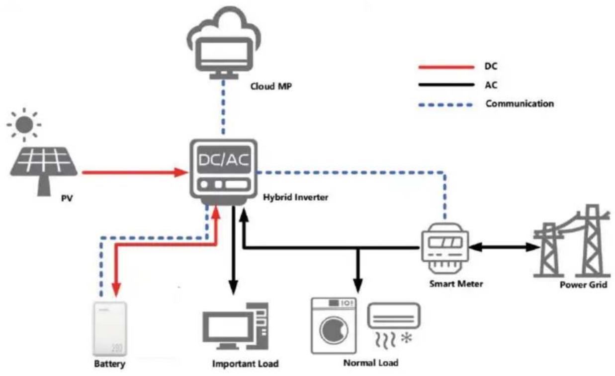
The battery pack is used to provide backup power, load shifting, peaking shaving and can be used for residential energy storage, solar energy storage and other application scenarios.
The normal working operation diagram of the battery pack can be as shown in the figure below.
flowchart
graph TD
    PV["Power Source PV"] --> DC["DC/AC"]
    DC --> CloudMP["Cloud MP"]
    CloudMP --> HybridInverter["Hybrid Inverter"]
    HybridInverter --> SmartMeter["Smart Meter"]
    SmartMeter --> PowerGrid["Power Grid"]
    DC --> Battery["Battery"]
    DC --> ImportantLoad["Important Load"]
    DC --> NormalLoad["Normal Load"]
    AC["AC"] --> SmartMeter
    AC --> Battery
    AC --> NormalLoad
    AC --> Battery
    AC --> NormalLoad
    AC --> Battery
    AC --> CloudMP
    CloudMP --> HybridInverter
    HybridInverter --> SmartMeter
    CloudMP -.-> CloudMP
    CloudMP -.-> HybridInverter
    CloudMP -.-> SmartMeter
    CloudMP -.-> PowerGrid
Fig. 3-1 Working Diagram of the Battery Pack
4.1 Parallel Connection Application
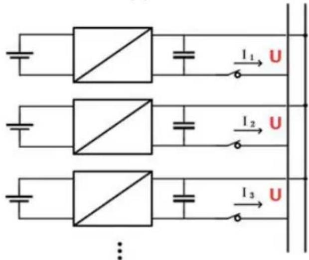
The battery packs support parallel connection, and synchronously increases the backup time or backup power.
Confirm the consistency between the battery packs, check the SOC and voltage and turn off the batteries before connecting them in parallel.
4.2 Low-temperature Application
• Low-temperature Charging
The battery pack does not support direct charging of the battery below 0^ C. When the minimum temperature of the battery is below 0^ C, the BMS will cut-off the charging circuit and cannot be charged.
- Low-temperature Discharging
The battery pack does not support discharge below -20^ . When the minimum temperature of battery is below -20^ , the BMS will cut-off the discharge circuit and cannot discharge.
4.3 Low Battery-capacity Storage (SOC≤5%)
After the battery pack is power off, there will be BMS static power consumption and self-discharge loss. In actual scenarios, it is necessary to avoid low-battery-power state (SOC≤5%) storage. If it is unavoidable, the longest storage period is 30 days @25°C, 15 days@45°C. The battery needs to be recharged in time after storage, otherwise the battery may be damaged due to over-discharge, and the entire battery pack needs to be replaced.
The following conditions may cause the battery pack to be stored in a discharged state:
- After the utility power failure, the line/fault cannot be eliminated in time, and the power supply cannot be restored for a long time.
• After the installation and commissioning work is completed, the utility power is turned off directly, but the battery pack is not powered off, which will cause the battery to enter the low power consumption mode. - Other reasons cause the battery pack to fail to enter low power consumption normally.
5 Product Introduction
5.1 Dimensions
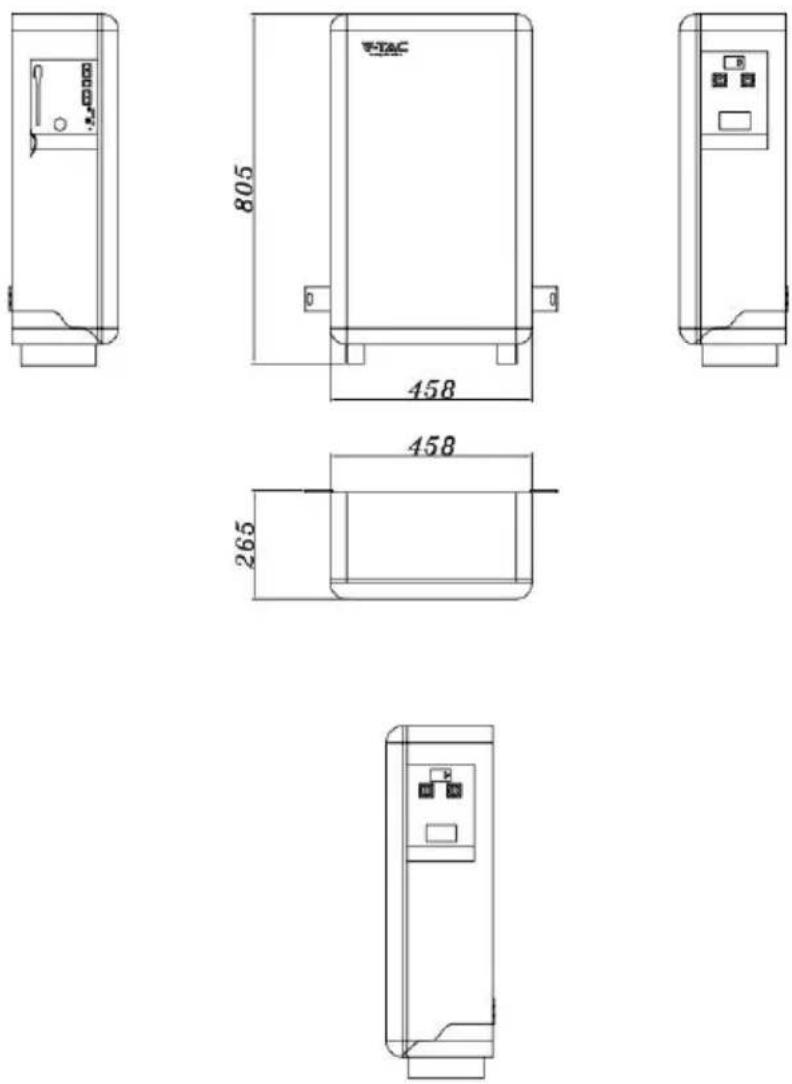
Fig. 5-1 Product Dimensions
5.2 Panel Introduction
The panel is shown as follows.
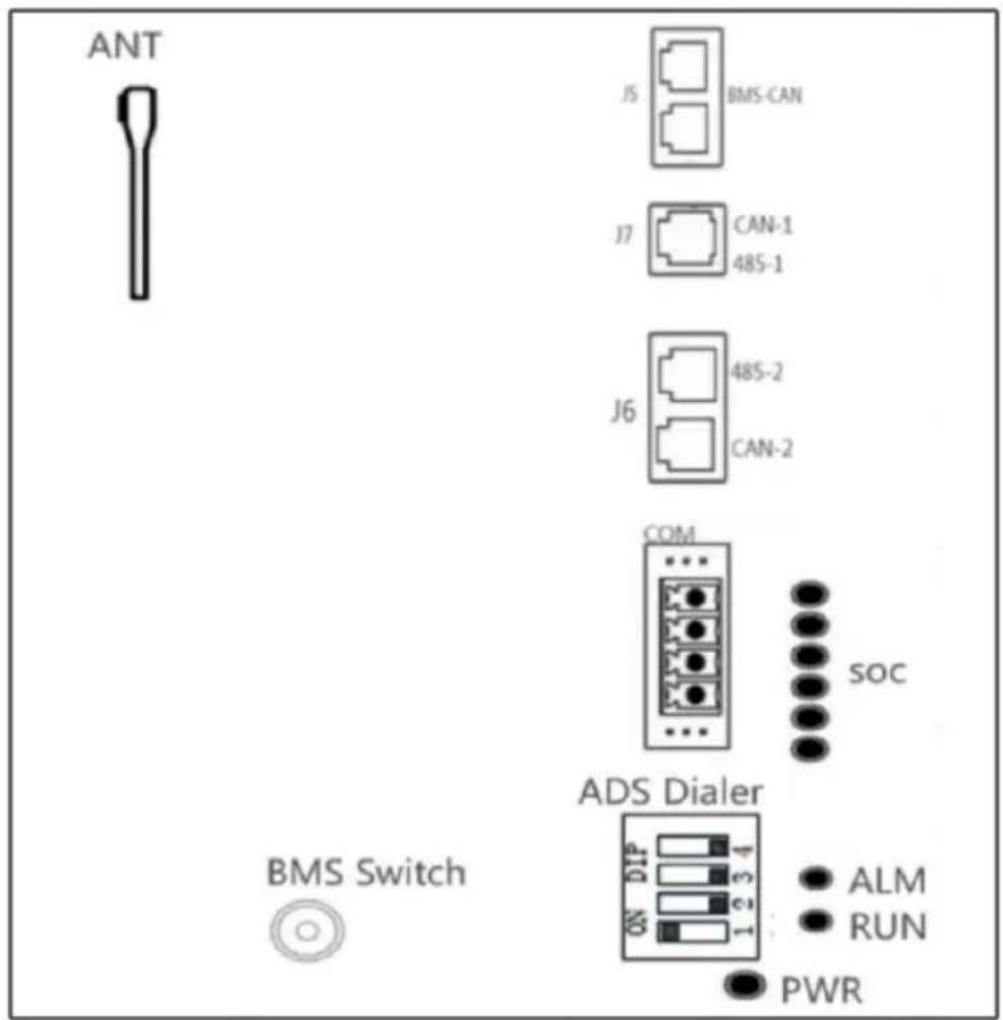
Fig. 5-2 Peration Panel
The definition of the VT-12040-1 operation panel is shown as follows.
Table 5-1 Operation Panel Interface Definition
| Items | Remark |
| SOC | State of charge |
| RUN/ALM | To indicate the running or alarm status of battery |
| J5 | J5 is used for communication between batteries. |
| J7 | J7 is used for debugging BMS. |
| J6 | J6 is used for communication with inverter . |
| PWR | Indicates the switching status of battery and prompts whether the battery device is on or off |
| COM | When alarms and protection occur, a closed loop is formed here |
| BMS SWITCH | Short time contact boot , Prolonged contact shutdown |
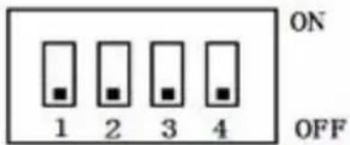
| ADS Dialer | Parallel address dip switch |
| ANT | Receive blue tooth signal |
The SOC indicator used to identify the current capacity status of the battery. The number of blinking indicators corresponds to different remaining capacity. The specific meaning is shown as follows.
Table 5-2 The SOC Indicator Definition
| No. | Indicator Light | Remark |
| 1 |  | 0% ≤ SOC ≤ 16% |
| 2 | 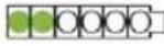 | 17% ≤ SOC ≤ 32% |
| 3 |  | 33% ≤ SOC ≤ 49% |
| 4 | 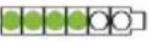 | 50% ≤ SOC ≤ 65% |
| 5 |  | 66%≤ SOC ≤ 83% |
| 6 | 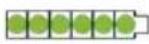 | 84%≤ SOC ≤ 100% |
Table 5-4 The Alarm Indicator Definition
| Indication Status | ON | OFF | Battery Status |
| Keep On | - | Fault ( Charge/Discharge MOS、NTC、ADC Fault、Reverse Connection Fault ) | |
| Keep Off | - | Standby/Sleep/No issue | |
Line specification:
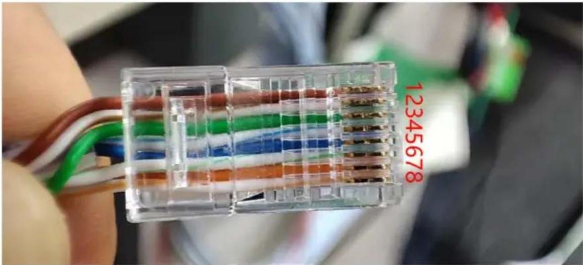
As shown in the figure: no buckle face up, from the top down, the line sequence is 12345678
Table 5-5 The Communication Port Definition
| J5/J6 | Pin | Description |
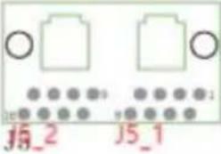 | (J5_1 / J5_2) 4 | CAN1-H(communicate with next battery) |
| (J5_1 / J5_2) 5 | CAN1-L (communicate with next battery) | |
| (J5_1 / J5_2) | VCC-12V (IOE Power ) | |
| (J5_1 / J5_2) | GND (IOE GND ) | |
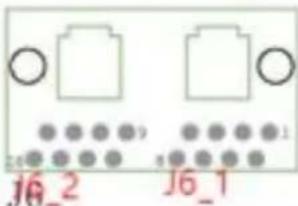 | (J6_1 / J6_2) 1/8 | 485-2B (communicate with the inverter) |
| (J6_1 / J6_2) 2/7 | 485-2A (communicate with the inverter) | |
| (J6_1 / J6_2) 4 | CAN2-H (communicate with the inverter) | |
| (J6_1 / J6_2) 5 | CAN2-L (communicate with the inverter) | |
| / | ||
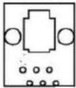 | J7 1 | reserve |
| J7 2 | reserve | |
| J7 4 | CAN-1H(communicate with the Upper computer) | |
| J7 5 | CAN-1L(communicate with the Upper computer) |
5.3Meaning of buzzer and LED light
When the battery is normal
| System State | RUN Light | SOC Light | Buzzer | ALM Light | ||||||
| SOC | LED1 | LED2 | LED3 | LED4 | LED5 | LED6 | ||||
| Charge | LED Light ON | 100% | ON | ON | ON | ON | ON | ON | / | OFF |
| 83%~99% | ON | ON | ON | ON | ON | Flash1 | ||||
| 67%~82% | ON | ON | ON | ON | Flash1 | OFF | ||||
| 51%~66% | ON | ON | ON | Flash1 | OFF | OFF | ||||
| 33%~50% | ON | ON | Flash1 | OFF | OFF | OFF | ||||
| 17%~32% | ON | Flash1 | OFF | OFF | OFF | OFF | ||||
| 0%~16% | Flash1 | OFF | OFF | OFF | OFF | OFF | ||||
| Discharge | Flash1 | 100%~84% | ON | ON | ON | ON | ON | ON | ||
| 83%~66% | ON | ON | ON | ON | ON | OFF | ||||
| 65%~50% | ON | ON | ON | ON | OFF | OFF | ||||
5 Product Introduction
| Discharge | Flash1 | 49%~33% | ON | ON | ON | OFF | OFF | OFF | |
| 32%~17% | ON | ON | OFF | OFF | OFF | OFF | |||
| 16%~8% | ON | OFF | OFF | OFF | OFF | OFF | Loud 4 | ||
| 7%~0% | Flash1 | OFF | OFF | OFF | OFF | OFF | Loud 1 | ||
| Standing | ON | 100%~84% | ON | ON | ON | ON | ON | ON | / |
| 83%~66% | ON | ON | ON | ON | ON | OFF | |||
| 65%~50% | ON | ON | ON | ON | OFF | OFF | |||
| 49%~33% | ON | ON | ON | OFF | OFF | OFF | |||
| 32%~17% | ON | ON | OFF | OFF | OFF | OFF | |||
| 0%~16% | ON | OFF | OFF | OFF | OFF | OFF | Loud 4 |
When the battery is fault
| Faults | RUN | ALR | LED1 | LED2 | LED3 | LED4 | LED5 | LED6 | Buzzer | Number |
| ID faults | OFF | ON | OFF | OFF | OFF | Flash1 | OFF | OFF | Loud | 04 |
| Cell Faults | OFF | ON | OFF | OFF | Flash1 | Flash1 | Flash1 | OFF | Loud | 14 |
| Precharge Faults | OFF | ON | OFF | Flash1 | OFF | OFF | OFF | OFF | Loud | 16 |
| D-Low temp Faults | OFF | ON | OFF | Flash1 | OFF | OFF | Flash1 | OFF | Loud1 | 18 |
| C-Low temp Faults | OFF | ON | OFF | Flash1 | OFF | Flash1 | OFF | OFF | Loud1 | 20 |
| Ultra high voltage | OFF | ON | OFF | Flash1 | OFF | Flash1 | Flash1 | OFF | loud | 22 |
| high voltage | OFF | ON | OFF | ON | ON | ON | ON | ON | NO-Loud | / |
| low voltage/Ultra Low Voltage | OFF | ON | OFF | Flash1 | Flash1 | OFF | OFF | OFF | Loud1 | 24 |
| D-High temp Faults | OFF | ON | OFF | Flash1 | Flash1 | OFF | Flash1 | OFF | Loud1 | 26 |
| Discharge over current | OFF | ON | OFF | Flash1 | Flash1 | Flash1 | Extinct | OFF | Loud | 28 |
| Discharge High temp Faults | OFF | ON | OFF | Flash1 | Flash1 | Flash1 | Flash1 | OFF | Loud1 | 30 |
| Charge Over current | OFF | ON | Flash1 | OFF | OFF | OFF | OFF | OFF | Loud | 32 |
| MOS High temp | OFF | ON | Flash1 | OFF | OFF | OFF | Flash1 | OFF | Loud1 | 34 |
| short out | OFF | ON | Flash1 | OFF | OFF | Flash1 | OFF | OFF | Loud | 36 |
| Environment H-T | OFF | ON | Flash1 | OFF | OFF | Flash1 | Flash1 | OFF | Loud | 38 |
| Environment L-T | OFF | ON | Flash1 | OFF | Flash1 | OFF | OFF | OFF | Loud | 40 |
| D-Low temp Faults | OFF | ON | OFF | Flash1 | OFF | OFF | Flash1 | OFF | Loud1 | 18 |
| Normal | ON | OFF | According to the SOC display | No-loud | / | |||||
5 Product Introduction
Annotation :
| Normal | Always | Extinct | According to the SOC display | No-loud | / | |
| explainNoun | Led | Buzzer | ||||
| Flash1 | One second at a time | / | ||||
| Loud | / | Always on | ||||
| Loud1 | / | One second at a time | ||||
| Loud4 | / | Sounds every four seconds | ||||
ADS Dialer instructions
When the battery PACK is used, different packs can be distinguished by the hardware address, and the hardware location of each PACK in the whole battery stack.
The address is unique, and the hardware address can be set sequentially by means of a dip switch on the board, which is defined in the table below.
Precautions for Installation
• Light intensity is required near the installation location.
- Comply with the safety operation technical regulations when lifting and handling heavy objects.
- Equipment and tools must be complete, intact, and reliable. It is strictly prohibited to use tools with cracks, burrs, loose handles, etc., that do not meet the safety standards.
• Installation operations must be guided by qualified engineers.
- During installation, two people must work together, one operating and the other inspecting.
- The original cable connection and operation process shall not change without the authorization of the company's consent.
6.1 Installation Preparation
• Light intensity is required near the installation location.
- Comply with the safety operation technical regulations when lifting and handling heavy objects.
- Equipment and tools must be complete, intact, and reliable. It is strictly prohibited to use tools with cracks, burrs, loose handles, etc., that do not meet the safety standards.
• Installation operations must be guided by qualified engineers.
- During installation, two people must work together, one operating and the other inspecting.
- The original cable connection and operation process shall not change without the authorization of the company's consent.
6.2 Installation Preparation
6.2.1 Tools Preparation
ATTENTION
Use insulated tools to avoid electric shock. If you use tools without insulation protection, you need to wrap the exposed metal parts with insulation tape for insulation treatment.
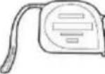
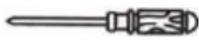
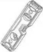
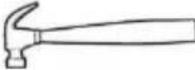
The following table describes the tools and meters that may be used before installation.
Table 6-1 Installation
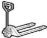
| Manual forklift | Electric forklift | Tape measure | Adjustable wrench |
 |  |  |  |
| Phillips screwdriver | Ladder | Levelling Instrument | Claw Hammer |
 |  |  |  |
| Socket wrench | Multimeter | Insulated torque wrench | Helmet |
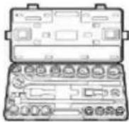 | 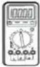 | 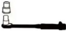 |  |
| Insulated shoes | Anti-static gloves | Goggles | Insulating tape |
 |  | 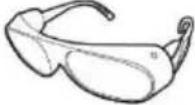 |  |

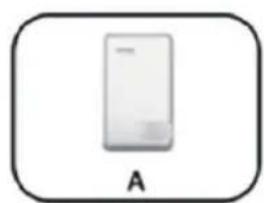
6.3 Packing List
natural_image
Simple icon of a rectangular device labeled 'A' (no text or symbols on the device itself)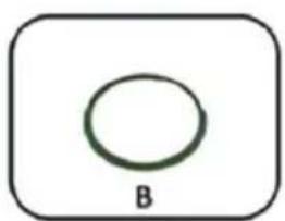
natural_image
Simple diagram with a circle inside a rounded rectangle labeled 'B' (no text or symbols within the shape)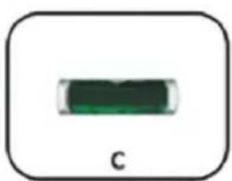
natural_image
Simple green rectangular object with label 'C' below, no visible text or symbols on the object itself.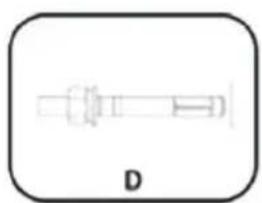
natural_image
Simple line drawing of a syringe with a label 'D' below it (no text or symbols on the diagram itself)
natural_image
Simple black irregular shape inside a rounded square frame, labeled 'I' below (no other text or symbols)
natural_image
Pure diagram of two symmetrical mechanical or architectural components with no text or symbols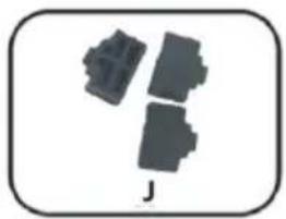
natural_image
Three gray plastic components arranged in a staggered layout, enclosed in a rounded square frame (no text or symbols)| Item | Description | Quantity |
| A | VT-12040-1 battery | 1 |
| B | GND cable | 1 |
| C | Spirit Level | 1 |
| D | Fixing Screws ( Expansion Bolt ) | 2 |
| E | User Manual | 1 |
| F | Warranty Card | 1 |
| G | Packing List | 1 |
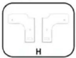
| H | Bracket | 2 |
| I | J7 Dust-proof plug | 1 |
| J | J5 J6 Dust-proof plug | 3 |

6.4 Unpacking and Inspection
After receiving the goods on-site, please check whether the packing box is intact and inspect the goods in time. If the packing box is slightly damaged, please sign the cargo list to confirm receipt and indicate the extent of the damage. If the damage of the packing box is serious, please refuse to sign.
Please carry out an unpacking inspection after receiving all the goods. If users find that the received goods do not match the packing list, please contact Vtac as soon as possible.
6.5 Installation
Step 1. Place the battery to a flat surface.

NOTE
- Please place the VT-12040-1 battery on a flat surface, ensuring there is adequate space on both sides of the battery (recommended to be greater than 200mm).
- If possible, the installation site should be as spacious and ventilated as possible. If the site is small and confined, please configure auxiliary heat dissipation equipment.
To ensure more stable installation, please mount the battery to the wall before use.
Step 2. Take out the 2pcs brackets from the battery package.
Step 2.1. Remove the screws from the back of the battery.
Step 2.2. Use the removed screws (Step 2.1) to fix the brackets to the back of the battery.
Step 2.3 Fix the 2pcs brackets to the battery.
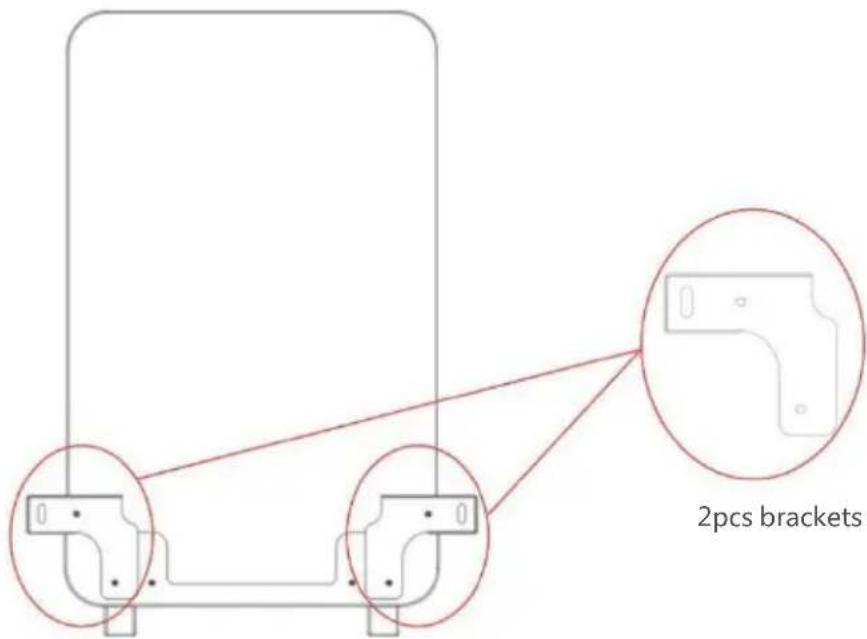
Fig.6-1 Fix the Brackets to the Battery
Step 3. Fix the 2pcs* 'Fixing screws' on the wall.
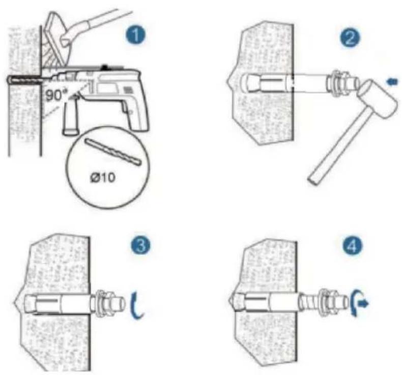
Fig.6-2 Fix the Battery to the Wall
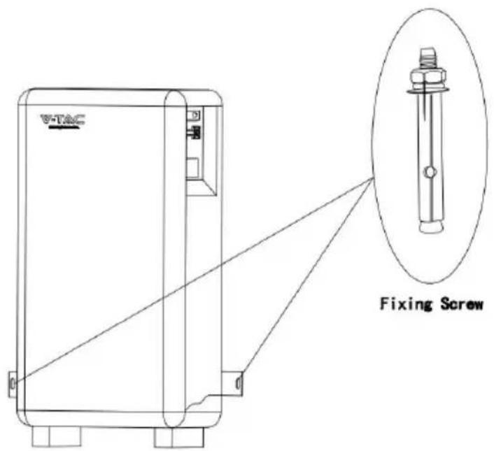
Fig.6-3 Fix the Battery to the Wall
6.6 Cable Connection
6.6.1 Power Cable Connection

NOTE
- Please contact Vtac or the supplier to purchase the following cables. They are maybe not included in the battery box and can be obtained in the Master/Slave Cable Kit provided by Vtac or the suppliers.
• How to use the touch-safe power cable connectors
Press the unlock on the power cable while inserting the power cable into the socket.
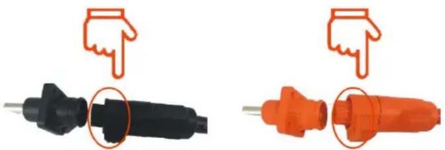
natural_image
Two types of electrical plug connectors shown in black and orange, each with a downward arrow indicating downward force (no text or symbols present)Press to unlock Press to unlock
The following is the power cables connection display of the battery to the inverter.
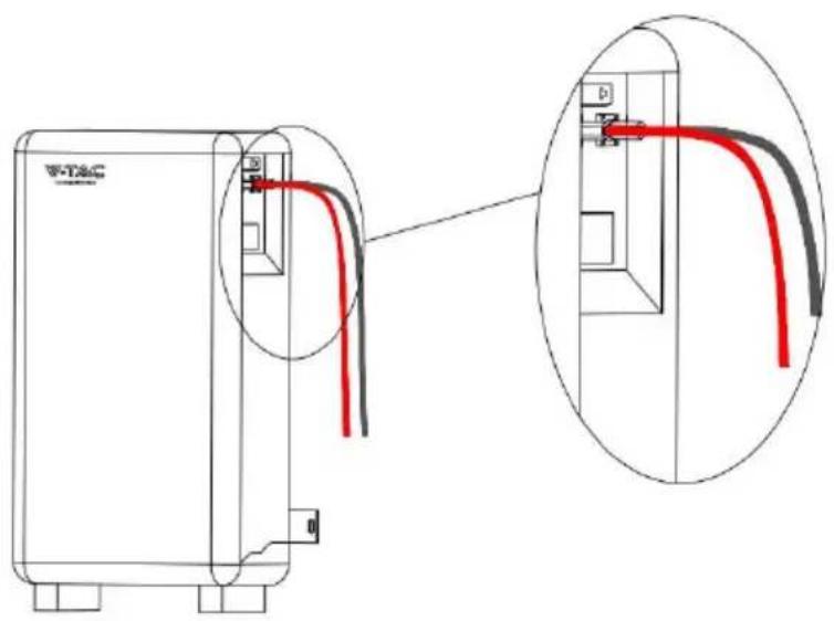
Fig.6-4 Power Cable Connection Diagram
6.6.2 Communication Cable Connection
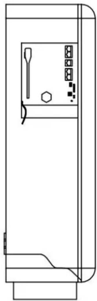
Locate the direction of the communication cable with the socket and then insert the communication cable to the socket.

NOTE
• How to use the communication cable connectors
Open the communication port cover, align it with the corresponding socket, and insert it.
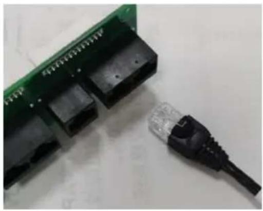
natural_image
Close-up of a green circuit board with black connectors and a black USB cable attached (no visible text or symbols)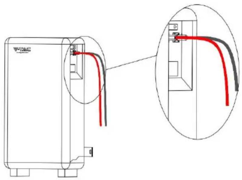
Fig.6-5 Communication Cable Connection Diagram
6.6.3 120Ω Resistor Connection
To ensure stable communication with the inverter when using more than two batteries in parallel, follow these steps:
Step 1. Take out a 120Ω resistor from the 'Slave Battery Kit'.
Step 2. Insert the 120Ω resistor into the 'COM 2' port of the last VT-12040-1.
6.6.4 Grounding Cable Connection
Connect the grounding cable to the ground.
natural_image
Technical line drawing of a cabinet or enclosure with internal components and no visible text or symbolsFig.6-6 GND Cable Connection Diagram
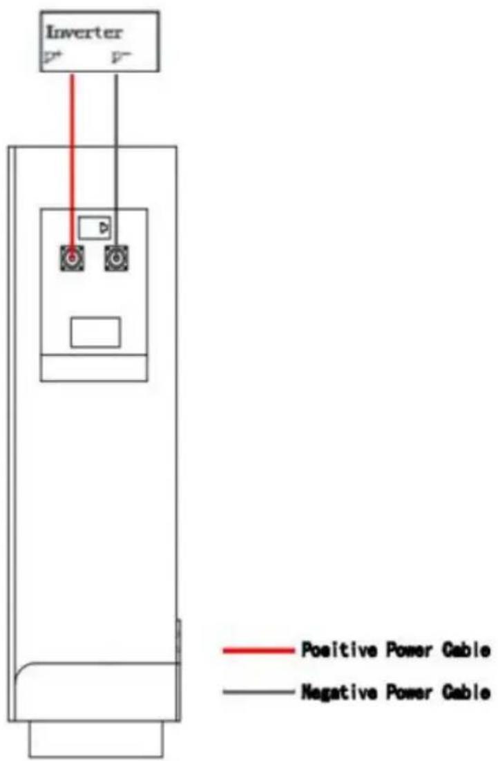
If you will install less than 2pcs batteries (Battery quantity≤2), please refer to the following wiring configuration.
| Battery Quantity of Parallel | Cable Kit |
| 1 PC | Master Cable Kit * 1 set |
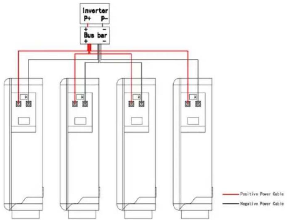
If you will install more than 2pcs batteries (No more than 15pcs), you will have the following two system wiring options.
Option 1. Connect all batteries to the bus bar.

NOTE
- For this wiring solution, you will need to prepare bus bars and power cables to connect the bus bars to the inverter in addition. You can either purchase them independently or obtain them from Vtac or the supplier.
- In this wiring solution, the Max. output current of the system will be 100A^* the quantity of batteries in parallel.
| Battery Quantity of Parallel | Cable Kit |
| 3 PCS | Master Cable Kit * 3 set |
| ⋮ | ⋮ |
| N PCS (4≤N<15) | Master Cable Kit * N set (4≤N<15) |
| ⋮ | ⋮ |
| 15 PCS | Master Cable Kit * 15 set |
flowchart
graph TD
    A["Inverter P+ P-"] --> B["Bus bar +"]
    B --> C1["Cell 1: P"]
    B --> C2["Cell 2: P"]
    B --> C3["Cell 3: P"]
    B --> C4["Cell 4: P"]
    C1 --> D1["Positive Power Cable"]
    C2 --> D2["Positive Power Cable"]
    C3 --> D3["Positive Power Cable"]
    C4 --> D4["Positive Power Cable"]
    D1 --> E1["Negative Power Cable"]
    D2 --> E2["Negative Power Cable"]
    D3 --> E3["Negative Power Cable"]
    D4 --> E4["Negative Power Cable"]

ATTENTION
- If you will install more than 2pcs batteries (Contains 2, no more than 15pcs), you need to pay attention to the connection of the parallel interface(J5).
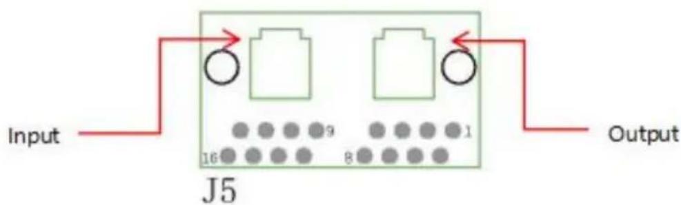
Fig 7-1 J5 Port Diagram
If you will install more than 2pcs batteries, be sure to connect from the output of the last J5 to the input of the next J5. To avoid damaging to the BMS.
The connection diagram is as follows.
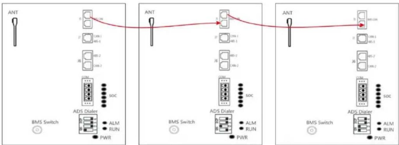
flowchart
graph LR
    subgraph Left_Switch
        ANT1["ANT"] -->|5| CAN1["CAN-1"]
        CAN1 -->|6| ANS1["AN-1"]
        ANS1 -->|7| CAN2["AN-2"]
        CAN2 -->|8| COM["COM"]
        COM -->|9| ADS_Dialer["ADS Dialer"]
        ADM["ALM"] -->|10| CAN3["CAN-1"]
        RUN["RUN"] -->|11| CAN4["AN-1"]
        PWR["PWR"] -->|12| CAN5["AN-2"]
        SOC["SOC"] -->|13| COM
    end
    subgraph Right_Switch
        ANT2["ANT"] -->|5| CAN5["CAN-1"]
        CAN5 -->|6| ANS2["AN-2"]
        ANS2 -->|7| CAN6["AN-2"]
        CAN6 -->|8| COM
        COM -->|9| ADS_Dialer["ADS Dialer"]
        ALM["ALM"] -->|10| CAN7["CAN-1"]
        RUN["RUN"] -->|11| CAN8["AN-1"]
        PWR["PWR"] -->|12| CAN9["AN-2"]
        SOC["SOC"] -->|13| COM
    end
    subgraph Right_Switch
        ANT3["ANT"] -->|5| BMS-LAN["AMS-LAN"]
        BMS-LAN -->|6| CAN10["CAN-1"]
        CAN10 -->|7| ANS3["AN-1"]
        ANS3 -->|8| CAN11["AN-1"]
        ANS11 -->|9| COM
        COM -->|10| ADS_Dialer["ADS Dialer"]
        ALM["ALM"] -->|11| CAN12["AN-2"]
        RUN["RUN"] -->|12| CAN13["AN-2"]
        PWR["PWR"] -->|13| COM
    end
Master Slaves 1 Slaves 2
ATTENTION
- Please strictly follow the steps below for check and operation. Vtac will not be responsible for any issues caused by improper operation.
Parameter Setting
Table 8-1 Parameter Setting
| No. | Description | Unit | Value |
| 1 | Nominal Voltage | V | 51.2 |
| 2 | Float Charge Voltage | V | 58.4 |
| 3 | Recommended Charge Current | A | 90 |
| 4 | Max. Charge/Discharge Current | A | 100 |
| 5 | Discharge Cut-off Voltage | V | 43.2 |
| 6 | Charge Temperature Range | °C | 0~55 |
| 7 | Discharge Temperature Range | °C | -20~60 |
| 8 | Storage Temperature Range | °C | 15~35 |

NOTE
- The setting of different inverters will be different.
- Make sure the inverter/charger is powered on before powering on the battery.
- Must not change the parameters casually in the site.
Check before Running
Step 1. Check whether the cables are connected correctly.
Step 2. Check whether the batteries are grounded.
Step 3. Check these following status of switch.
The power switch of the battery should be off.
The DC switch of the inverter should be off.
The circuit breaker from the inverter to the grid should be off.
Power-on
Step 4. Turn on the DC switch of inverter.
Turn on the switch between the inverter and grid.
Turn on the circuit breaker between the inverter and battery (if any).
Step 5. Turn on the power switch of battery. And waiting for the Run/Alarm indicator lights from green blinking into green, means power on successfully!

NOTE
• If you want to Power off your system
If you need to shut down the system for some reason, please refer to the following steps.
Step 1. Turn off the inverter first.
Step 2. Turn off the battery then.
9.1 Shipment
It is suitable for the transportation of vehicles, ships and airplanes. During transportation, shading, sun protection and civilized loading and unloading should be performed. The box containing the product is allowed to be transported by any means of transportation. In the process of loading and unloading, the battery should be handled with care to prevent falling, rolling, and heavy pressure. Avoid direct rain and snow and mechanical impact during transportation.
And here is the suggestion for the initial SOC before shipment by different transportation:
- Airplane:30%\~40%
- Sea:40%\~50%
• Vehicle:50%\~60%

NOTE
- Whether the loading SOC status of the battery is allowed, you need to consult the relevant government transportation department.
9.2 Maintenance
9.2.1 Battery Maintenance Considerations
When maintaining the battery, it is required to use insulated tools or wrap the tools in insulation.
• DO NOT place any debris on the top of the battery.
DO NOT use any organic solvents to clean the battery.
DO NOT smoke or use naked flames near the battery.
• After the battery is discharged, the battery should be charged in time to avoid
• affecting the battery life.
- When not using the battery for a long time, please charge the battery to 40%\~50% charged state. Long-term storage with low battery may
• damage the battery.
All maintenance work must be carried out by professionals.
9.2.2 Routine Maintenance
The staff should perform visual inspection on VT-12040-1 battery according to the inspection plan, please refer to the following table for maintenance.
Table 9-1 Routine Maintenance ( Every three-month )
| Items | Standard | Dealing |
| Battery Appearance | The surface is neat and clean without stains.The terminals are in good condition.The battery pack shell is intact, and there is no bumps, breaks, or leakage.The appearance of the battery pack does not leak.No deformation or swelling of the shell. | If the surface is dirty, clean the appearance of the battery pack with a cotton cloth.The battery pack terminal is damaged, replace the cable.If the appearance is damaged, leaking or deformed, take a photo and replace the defective battery pack.Please contact supplier or the authorized dealers in time for other abnormal situations. |
| Alarm | No Alarm. | Find the solution as per alarm information. |

NOTE
- Suggested routine maintenance for every three-month.
Table 9-2 Routine Maintenance ( Every six-month )
| Items | Standard | Action |
| ( Suggested ) Complete Cycle | Have a complete charge & discharge cycle under the equipment no lack of power. | Check whether happens alarm action, and please check with the alarm list.Please contact with supplier or the authorized dealers if the alarm still exists. |
| Cables | There is no aging of the connecting wire and no cracking of the insulation layer.The bolts at the cable connection are not loose. | Replace the faulty connection.Fastening bolts. |

9.3 Battery Storage
- The recommended storage temperature is 15°C\~35°C.
- Battery performance degradation after long-term storage, please shorten shelf time as possible as you can.
- Recharge charge before using to recover capacity loss of self-discharge during storage and transport.
- Storage battery should be at 40%-50% SOC when the battery is not used for a long time.
• Storage battery over 40^ C or under 0^ C will reduce battery life.
• Storage battery in dry and low temperature, well ventilated place.
If the battery is not used for a long time, the battery must be charged at regular intervals. The charging requirements are as follows :
Table 9-3 Battery Charge Requirement in Storage Status
| Storage Temp. | Charge Period | Charge Process |
| 20°C~30°C | Each 6 months | 1. Charge by 0.2C to 100% SOC2. Discharge by 0.2C to 0% SOC3. Charge by 0.2C to 40%~50% SOC |
| 0°C~20°C or 30°C~40°C | Each 3 months |
Please refer to the table below to deal with common faults :
Table 10-1 FAQ
| Phenomenon | Possible cause | Solution |
| The indicator does not flash | The power cable of the battery pack is not properly connected.The power switch is off.The BMS is in a sleep state.BMS is damaged. | Reconnect the power cable of the battery pack.Turn on the power switch.Charge the battery pack.Replace BMS. |
| Unable to discharge | The terminal of the battery pack is damaged.BMS communication failure.The power switch is off. | Replace the battery pack wiring terminals.Reconnect the communication line between the BMS and the battery pack. If the communication cable is damaged, replace the communication cable.Turn on the power switch. |
| Unable to charge | The charger is malfunctioning.The terminal of the battery pack is damaged.BMS communication failure.The power switch is off. | Replace the charger.Replace the battery pack wiring terminals.Reconnect the communication line between the BMS and the battery pack. If the communication cable is damaged, replace the communication cable.Turn on the power switch. |
| Communication fail | The power switch is off.The BMS is in a sleep status.The communication cable is damage. | Turn on the power switch.Charge the battery pack.Replace the network cable. |
| Inaccurate voltage display | The voltage sampling line is damaged.BMS is damaged. | Replace the voltage sampling line.Replace BMS. |
| Low capacity | The battery pack has not been maintained for a long time.The single battery is damaged.Inaccurate voltage sampling. | Use an equalizer to maintain the battery pack.Replace the damaged single battery.Replace the electrical sampling line or replace the BMS. |
| Low cell voltage | The battery pack has not been maintained for a long time.The single battery is damaged.Inaccurate voltage sampling. | Use an equalizer to maintain the battery pack.Replace the damaged single battery.Replace the electrical sampling line or replace the BMS. |
Except for the following and the conditions specified in the contract, you can go to the supplier or the authorized dealers for reasonable warranty and maintenance.
- Failure of equipment caused by unauthorized disassembly and maintenance operations without the supplier or the authorized dealers is not within the scope of the warranty.
- Equipment damage caused by negligence during storage and transportation is not covered by the warranty.
- The damage to the equipment caused by continuous overload work outside the electrical parameters of the equipment is not covered by the warranty.
- Unauthorized testing of the equipment without the supplier and the authorized dealers will not be covered by the warranty.
- Non-equipment problems, adverse consequences caused by operation and matching problems are not covered by the warranty.
- Equipment damage caused by natural forces, force majeure, and out of control factors, such as earthquakes, typhoons, tornadoes, volcanic eruptions, floods, lightning, heavy snow, and wars, is not covered by the warranty.
- If the product serial number is changed, blurred, or torn, it is not covered by the warranty.
IMPORTANT NOTES
- This product contains battery type "Secondary" (rechargeable).
- Electrical and electronic equipment that has become waste is known as old equipment/device. Old devices must not be disposed of with other household waste.
- Owners of old devices at the end of its service life must return the device by taking them to the collection points set up by public waste disposal authorities or distributors. This return does not entail any costs for you.
- Owners of old devices have an obligation to remove accessible batteries / rechargeable batteries as well as non-destructively removable lamps from the old device prior to return. This does not apply if old devices are being prepared for reuse with the participation of a public law firm.
- Battery removal warning: The battery contained in this product must be removed only by professional personnel only. The battery must never be removed by the end user, if not removed correctly it could damage the battery which could cause fire.
- Batteries removed from an old electronic device should be disposed of separately. This return of battery does not entail any costs for you and the user is obliged to return the battery.
- Please make sure that this product is not powered on when removing the battery. Fire hazard! Avoid short-circuiting the contacts of a detached battery. Do not incinerate the battery. Please handle the battery with Caution!
- If electrical appliances or batteries are disposed of in landfills or dumps, hazardous substances can leak into the groundwater and get into the food chain, damaging your health and well-being
- The symbol of "Crossed rubbish bins" indicates that this product should not be disposed of with other household wastes and must be collected separately from unsorted municipal waste at the end of its service life.
- Please use the link below to view the online directory of the collection and return points:https://www.ear-system.de/ear-verzeichnis/sammel-und-ruecknahmestellen
12 Abbreviations
BMS Battery Management System
D Depth
H Height
W Width
LCD Liquid Crystal Display
LFP LiFePO4
MOSFET Metal-Oxide-Semiconductor Field-Effect Transistor
NTC Negative Temperature Coefficient
PC Personal Computer
PCB Printed Circuit Board
PCS Power Conversion System
RTU Remote Terminal Unit
SOC State of charge
RoHS
CE
UKCA



13.Screen instructions
- After the battery is turned on, enter the Home main interface, the displayed contents include V,I,SOC, and SOH.
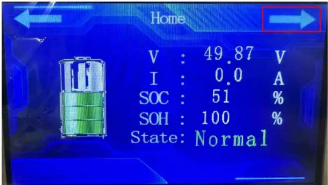
| Interface | Abbreviation of name | Full name |
| Home | V | Voltage |
| I | Current | |
| SOC | State Of Charge | |
| SOH | State Of Health |
Click → as shown in the picture to enter the second interface.
- The contents displayed on the second page include Address, Rem Cap, Tot Cap, TEMP1-4, Env Temp, MOS Temp, and CELLS1-16.
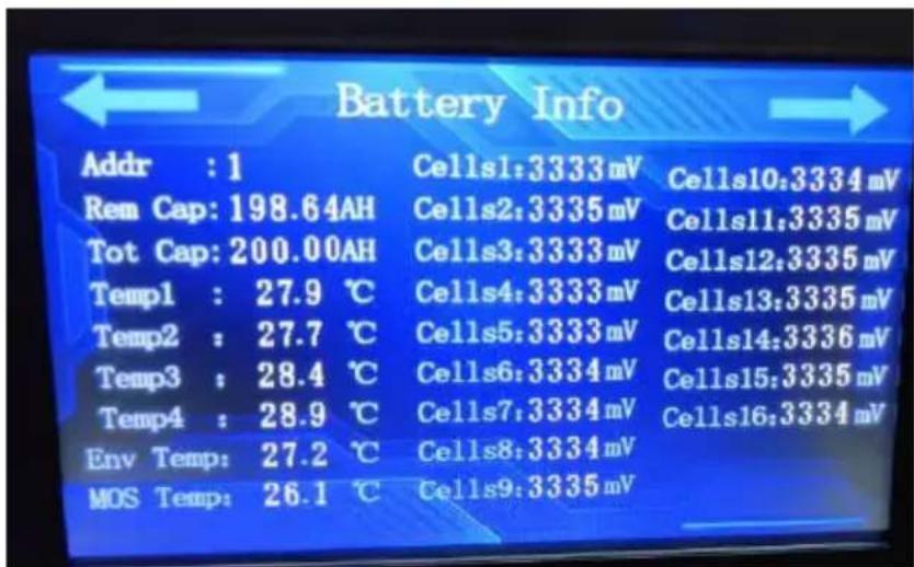
13.Screen instructions
| Battery Info | Abbreviation of name | Full name |
| Addr | Address | |
| Rem Cap | Remnant capacity | |
| Tot Cap | Total capacity | |
| Temp1~4 | Temperature1~4 | |
| Env Temp | Environment temperature | |
| MOS Temp | MOS temperature | |
| Cells1~16 | Cells1~16 |
Click → as shown in the picture to enter the third interface.
- The contents displayed on the third page include TV_L, TV_H, SV_L, SV_H, D_C, C_C, S_C, D_T_H, and C_T_H
, D_T_L, C_T_L, MOS_H, SV_H_H, SV_L_L, E_H, TV_H_H, PRE_CHA, ID_OVER, BAT_FAULT
E_L and other protection and alarm, when triggered from green to red
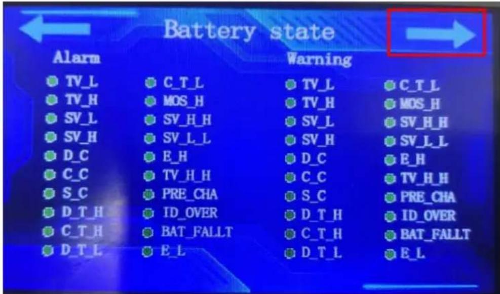
| Battery State | TV_L | Total voltage_low |
| TV_H | Total voltage_high | |
| SV_L | Single voltage_low | |
| SV_H | Single voltage_high | |
| D_C | Discharge_current | |
| C_C | Charge_current | |
| S_C | Short_current | |
| D_T_H | Discharge temperature_high (auto cut off) | |
| C_T_H | Charge temperature_high | |
| D_T_L | Discharge temperature_low | |
| C_T_L | Charge temperature_low |
13.Screen instructions
| MOS_H | MOS temperature_high | |
| SV_H_H | Single voltage high_high | |
| SV_L_L | Single voltage low_low | |
| E_H | Environment temperature_high | |
| TV_H_H | Total voltage is high_high | |
| PRE_CHA | Pre_charge fault | |
| ID_OVER | ID_Overtime | |
| BAT_FAULT | Battery_Fault | |
| E_L | Environment temperature_low |
Click → as shown in the picture to enter the fourth interface.
4、The Inverter, language, and Version are displayed.
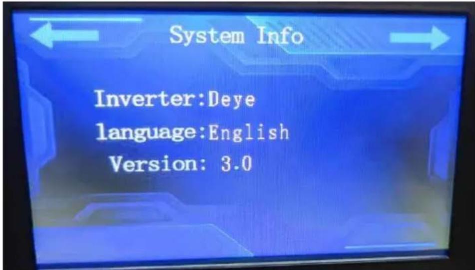
| System Info | Inverter | Inverter |
| language | language | |
| Version | Version |
Click ← as shown in the picture to return to the third interface.
1. Overview
IOE APP allows users to connect to devices by turning on Bluetooth, and has rich device information synchronization functions, allowing users to easily obtain detailed device data and grasp device status in real time. At the same time, its remote control function can keep the equipment in optimal operating condition anytime and anywhere.
When users open the APP and connect to the battery, they can see various detailed data, such as voltage, current, temperature, power, SOC and other information. It also supports battery parameter modification and synchronizes data updates for users in real time, allowing users to quickly make immediate adjustments to the battery. Visual query management and intelligent monitoring of battery status.
2. Software Features
2.1 Language Settings
The international common language English is used as the default language. In order to facilitate more users to use it, the APP provides Chinese and English bilingual versions, which can be freely switched according to user needs.
2.2 Visual Query Management
Users can use the query function in the APP to conduct visual information query on the battery, making it convenient for users to view real-time battery information anytime and anywhere, and helping users intuitively understand the system operation.
2.3 Interface Design
The interface is simple and refreshing, mainly using blue and white as the background color, giving a fresh and transparent feeling and bringing a comfortable experience to users.
2.4 Information Collection
The APP can capture battery information in real time, including voltage, current, temperature, battery capacity, SOC and other information. The latest battery data information can be collected in the shortest time, and the information can be released through the APP as soon as possible, thereby improving the timeliness and visualization of the information.
2.5 Intelligent Monitoring
The APP can intelligently monitor the battery status, realize instant alarm, notify relevant personnel to deal with it as soon as possible, and protect the battery status.
3.APP Installation Process
Scan the QR code below to enter the APP download page. After entering the download page,
14. Wireless module instructions(APP)
click the three... buttons in the upper right corner and click to open it with a browser and download it to install the APP.
4. 4.Instructions for use
(1) Installation via QR code.
Stp1. Scan the QR code on the right.
Stp2. If you use the scan function through wechat or other
software, you need to open it in the browser and enter Download
interface, Figure 2, Figure 3. If you use the mobile phone to
scan, go directly to Figure 3 to Download Screen.
Figure 1: Download QR
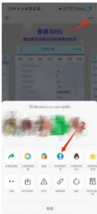
Figure 2: Go to the browser
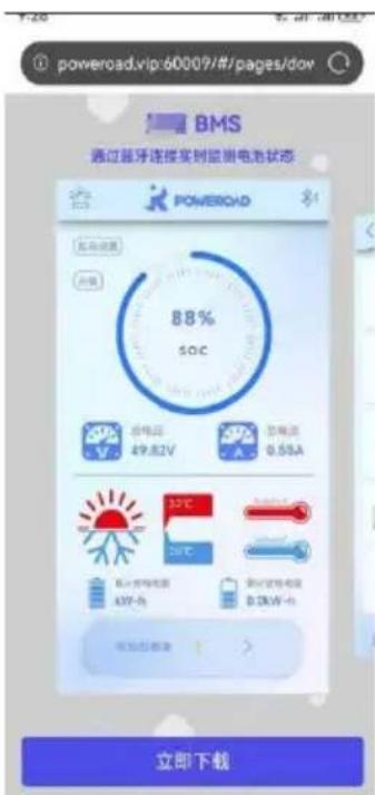
Figure 3: Go to the browser

Stp3. Click Figure 3 to download immediately, and the APK installation package will appear on the Android terminal, as shown in Figure 4. After downloading, install it, as shown in Figure 5. IOS directly enters the APP Store for download and installation, as shown in Figure 6.
14. Wireless module instructions(APP)
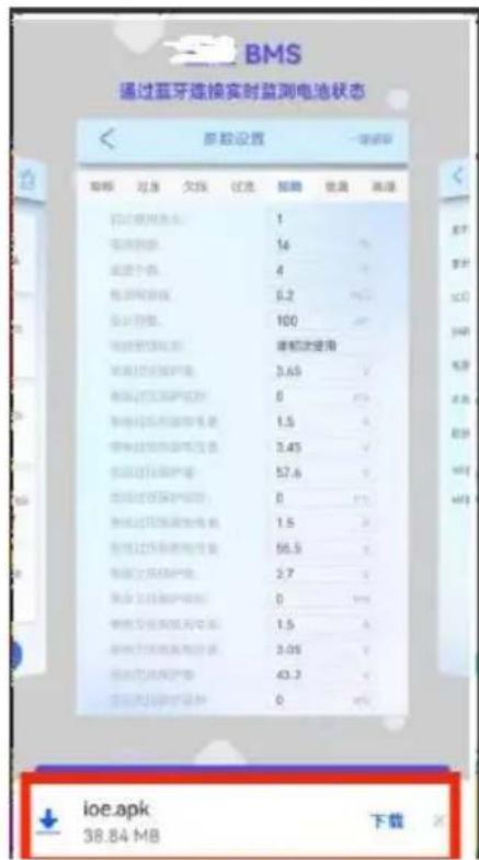
Figure 4: Browser download
Figure 5:Android installation
Figure 6: IOS installation
You can also search for IOE green energy through Google Play or IOS APP store to download and install it, as shown in the figure below.
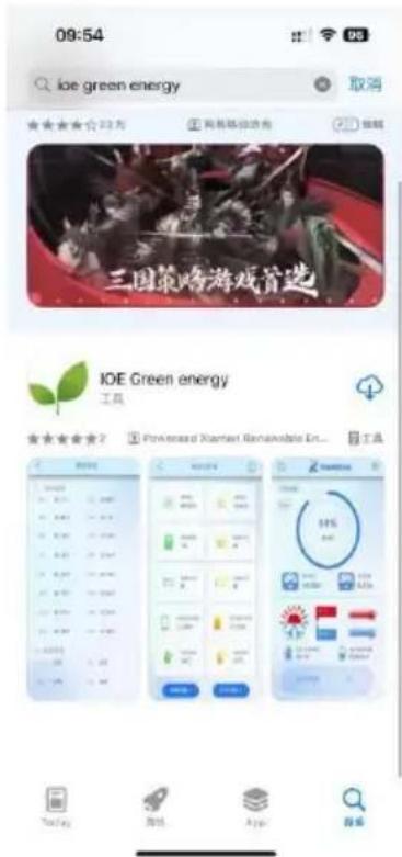
Figure 7: Search for downloads
14. Wireless module instructions(APP)
4.1 Log in
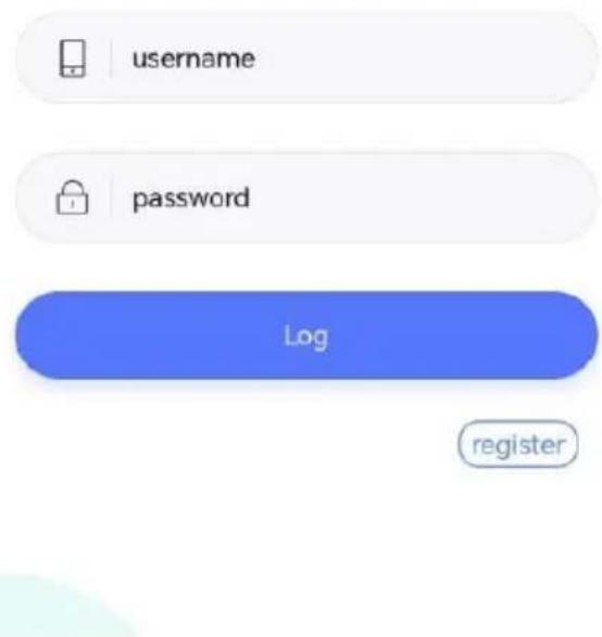
Figure: Log in
Page description: This picture is the APP login page. You can enter the user's account (email) and password to log in.
Click "EN" to enter the Chinese login interface.
Click "register" to jump to the registration page.
4.2 Register
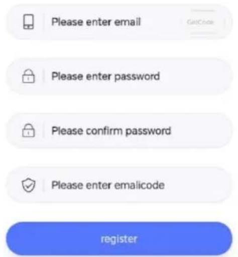
Figure: register
14. Wireless module instructions(APP)
Page description: This picture shows the APP registration page. You can enter your email (login account), password, confirmation password, and email verification code to complete the registration operation. Email verification code is valid for 2 hours
4.3 APP Homepage
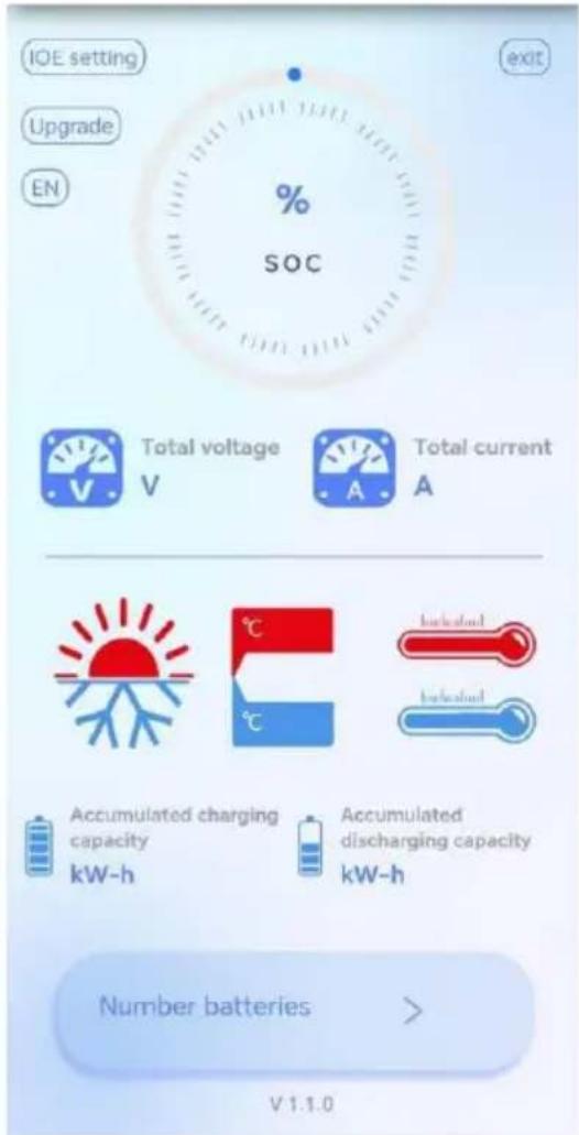
Figure 1 : APP home page
14. Wireless module instructions(APP)
Page description: This picture is the homepage of the APP. The instrument panel shows the SOC value. Under the dashboard is the total voltage, total current, maximum temperature, minimum temperature, cumulative charging capacity, and cumulative discharge capacity.
Click "Number batteries" to jump to the battery pack list page.
Click the "Bluetooth icon" in the upper right corner to jump to the Bluetooth connection page.
Click the "alarm icon " in the upper left corner to jump to the system alarm viewing page.
Click "IOE setting" to reach the system settings page.
Click "Upgrade" to choose to upgrade CM100 or BMS.
Click "EN" to switch to the Chinese version.
4.4 Bluetooth Connection
Click the Bluetooth icon to jump to the Bluetooth connection interface, as shown in Figure 2:
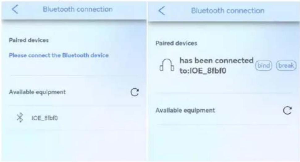
Figure 2 : Bluetooth connection interface
Page description: This picture is the Bluetooth connection page. Initialize the page or click the refresh button to open the nearby Bluetooth search function. Click the device you want to connect to in the obtained device list. After clicking Connect, it will prompt that the connection is successful and it will show that it has been connected to he device you want (Bluetooth name)
The default naming rule of Bluetooth is: IOE_XXXXX
Click to bind Bluetooth. After binding, the battery cloud data will be obtained by default every time you enter the APP. (WiFi information needs to be configured)
Click to disconnect the Bluetooth connection.
4.5 IOE Setting
Click "IOE setting" on the homepage to enter the setting interface, as shown in Figure 4
14. Wireless module instructions(APP)
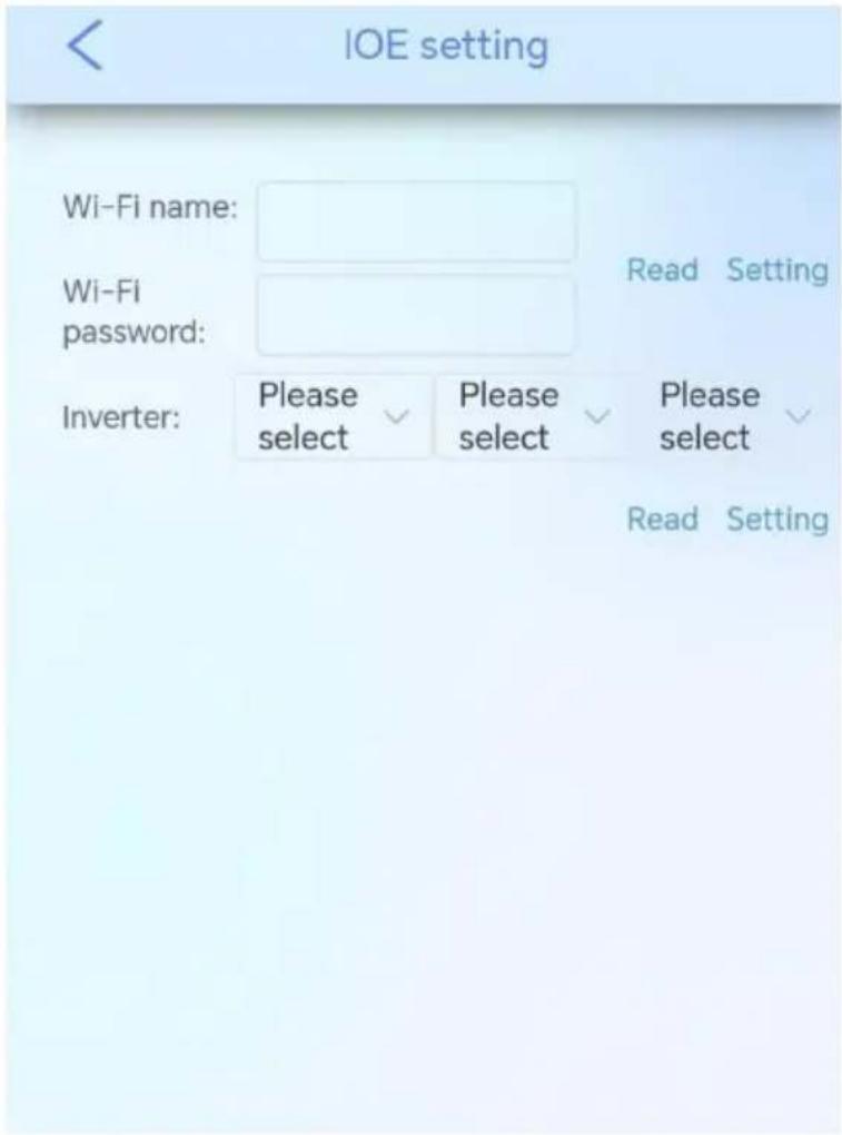
Figure 4 : IOE setting
Page description: This picture is the IOE setting page, which can read and set the Wi-Fi name& password and select inverter.
14. Wireless module instructions(APP)
4.5.1 Inverter Selection
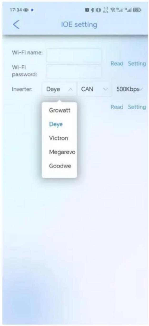
Figure 5 : Inverter selection
The inverter selection currently supports ten models, two communication methods (CAN/RS485), and multiple frequency options.
4.5.2 WIFI Setting
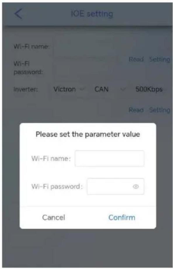
Figure 6: WIFI setting
Click WiFi Setting, then a setting box will pop up. After entering the WiFi information and clicking Confirm, the WiFi information of the communication box will be set.
4.6 Battery Pack Information
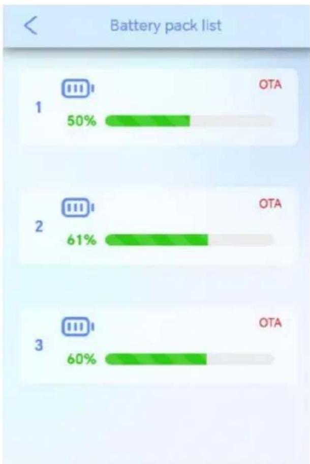
Click "Number batteries" on the homepage to jump to the battery pack list page, as shown in Figure 7
bar
Battery pack list | Category | Value (%) | |---|---| | 1 | 50 | | 2 | 61 | | 3 | 60 | OTAFigure 7 : Battery pack list
Page description: This picture is the battery pack list page, which can display the SOC of multiple battery packs. Click on a single pack to jump to the corresponding battery pack details page, as shown in Figure 8
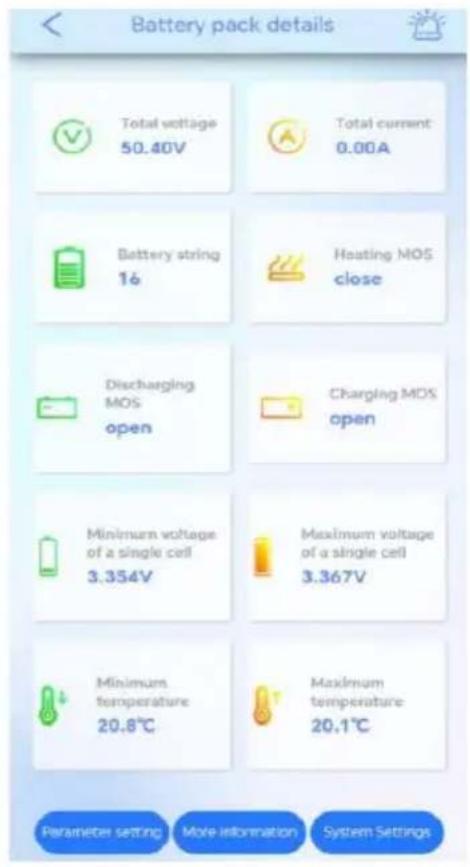
Figure 8: Battery pack details
Page description: This picture is the battery pack information page, which can display the total voltage, total current, battery string number, heating MOS, discharge MOS, charging MOS, minimum voltage of a single cell, maximum voltage of a single cell, maximum temperature, and minimum of the battery pack. Temperature.
4.7 More Information
Click on more information about the battery pack details to jump to the more information page, as shown below:
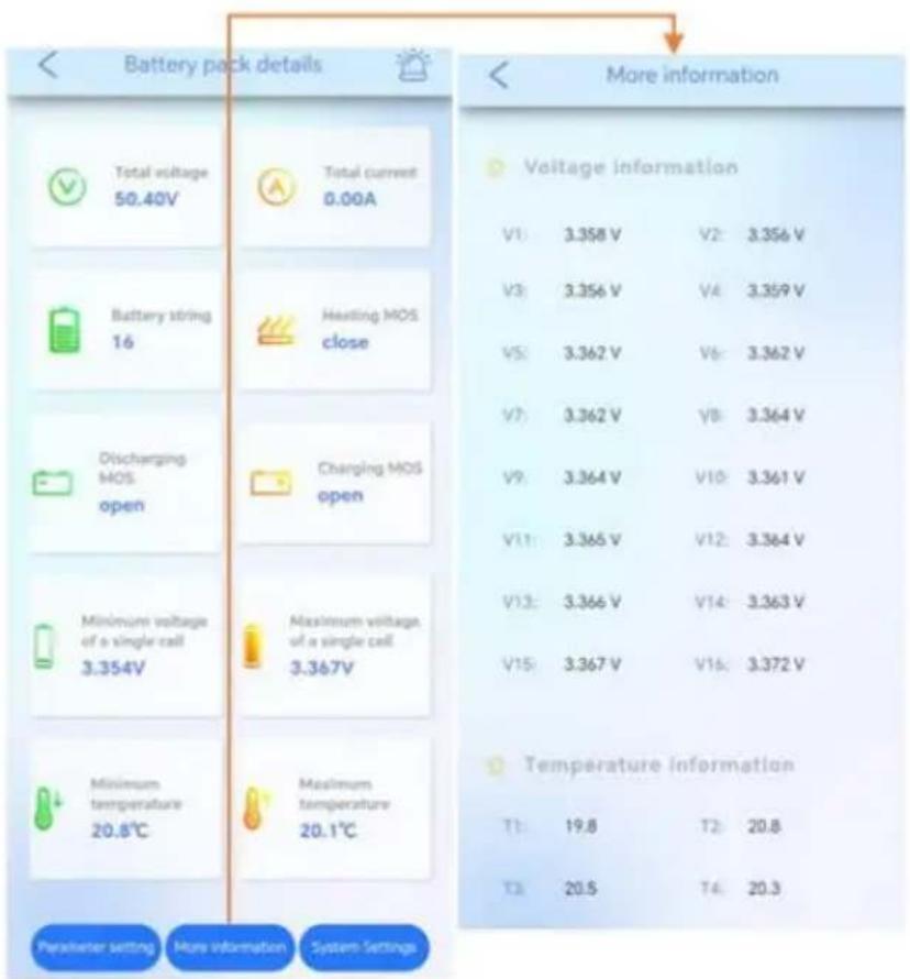
Figure 9: More Information
This page can display the voltage information from V1 to V16 and the temperature information from T1 to T4 to facilitate users to check the battery status.
4.8 System Alarm
Click the alarm icon in the upper right corner of the battery pack details to view system alarm information, allowing users to immediately understand the problem, as shown below:
14. Wireless module instructions(APP)
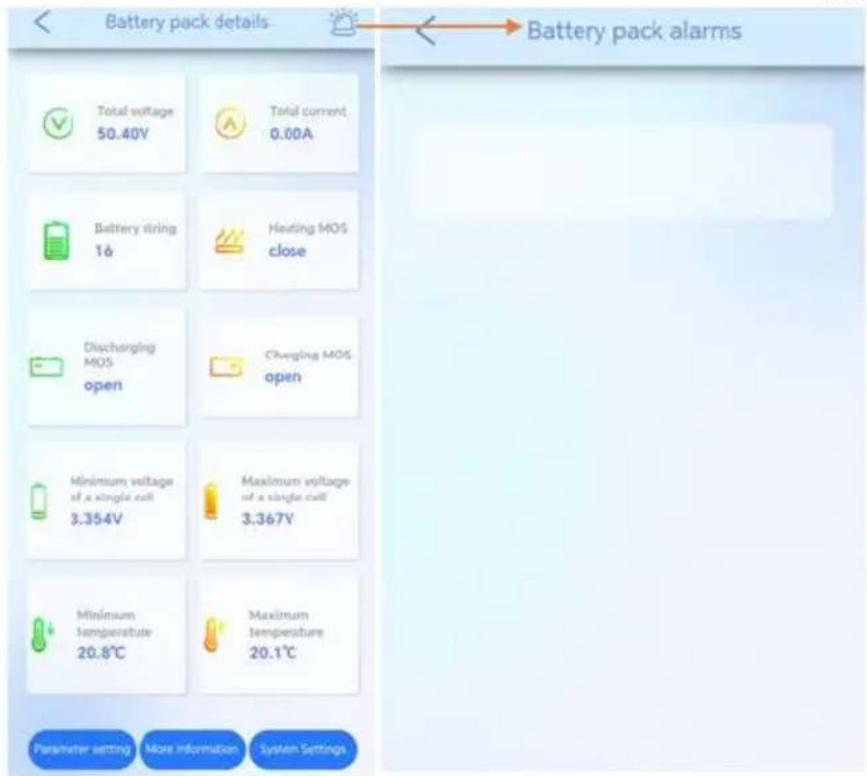
Figure 10:System alarm
Recommend charging method declared by the manufacturer :
Charge the battery at constant current 90A until voltage reaches 58.4V, then charge at constant voltage 58.4V till charge current is 10.3A.
Manufacturer's Name: LEDXPRESS LIGHTING TECHNOLOGY CO.,LTD
Product name: Lithium Ion Batteries
Model : VT-12040-1
Operating Temperature: -20°C to 60°C
This device was tested for operations. To comply with RF exposure requirements, a minimum separation distance of 20 cm must be maintained between the user's body and the handset, including the antenna. Third-party belt-clips, holsters, and similar accessories used by this device should not contain any metallic components. Body-worn accessories that do not meet these requirements may not comply with RF exposure requirements and should be avoided. Use only the supplied or an approved antenna.
This device in compliance with the essential requirements and other relevant provisions of Directive 2014/53/EU. All essential radio test suites have been carried out.
- Use careful with the earphone maybe possible excessive sound pressure from earphones and
headphones can
cause hearing loss.

- CAUTION : RISK OF EXPLOSION IF BATTERY IS REPLACED BY AN INCORRECT TYPE. DISPOSE OF USED BATTERIES
ACCORDING TO THE INSTRUCTIONS
-
The product shall only be connected to a USB interface of version USB 2.0
-
Adapter shall be installed near the equipment and shall be easily accessible.
-
The plug considered as disconnect device of adapter
-
The device complies with RF specifications when the device used at 20 cm form your body
-
This product can be used across EU member states.

V-TAC
Meaningful Innovation.
VTAC EUROPE LTD
Bulgaria, Plovdiv 4000, bul.L.Karavelow 9B
- INSTRUCTION MANUAL
- INTRODUCTION
- MULTI-LANGUAGE MANUAL QR CODE
- Overview
- Reader
- Signs
- Symbol Description
- Safety Precautions
- Abuse Operation
- Product Description
- Features
- •High energy density
- - Maintenance-free
- - Long cycle life
- •Excellent temperature characteristics
- Basic Functions
- - Monitor
- • Alarm
- - Communication
- • Parallel connection application
- • Balance function
- Application Scenario
- Parallel Connection Application
- Low-temperature Application
- • Low-temperature Charging
- - Low-temperature Discharging
- Low Battery-capacity Storage (SOC≤5%)
- Product Introduction
- Dimensions
- Panel Introduction
- 5.3Meaning of buzzer and LED light
- Precautions for Installation
- Installation Preparation
- Installation Preparation
- Tools Preparation
- ATTENTION
- Packing List
- Unpacking and Inspection
- Installation
- NOTE
- Cable Connection
- Power Cable Connection
- Communication Cable Connection
- • How to use the communication cable connectors
- 120Ω Resistor Connection
- Grounding Cable Connection
- Parameter Setting
- Check before Running
- Power-on
- • If you want to Power off your system
- Shipment
- Maintenance
- Battery Maintenance Considerations
- Routine Maintenance
- Battery Storage
- IMPORTANT NOTES
- Abbreviations
- 13.Screen instructions
- Overview
- Software Features
- Language Settings
- Visual Query Management
- Interface Design
- Information Collection
- Intelligent Monitoring
- 3.APP Installation Process
- Wireless module instructions(APP)
- 4.Instructions for use
- Log in
- Register
- APP Homepage
- Bluetooth Connection
- IOE Setting
- Inverter Selection
- WIFI Setting
- Battery Pack Information
- More Information
- System Alarm
- V-TAC
Brand : V-TAC
Model : VT-12040-1
Category : Uncategorized