
ETVX16S18DA9W - PC Fan DAIKIN - Free user manual and instructions
Find the device manual for free ETVX16S18DA9W DAIKIN in PDF.


| Product Type | Heat pump indoor unit (floor-standing) |
| Model | ETVX16S18DA9W |
| Brand | Daikin |
| Refrigerant | R32 |
| Capacity Class | 16 (heating/cooling) |
| Integrated DHW Tank | Yes, 23 L, stainless steel |
| Backup Heater Model | 9W (230 V 3~, 4 steps) |
| Power Supply | 230 V 3~ |
| Operation Modes | Heating, cooling, domestic hot water |
| Control Interface | User interface with room thermostat functionality |
| Weather-Dependent Control | Yes, with 2-point or slope-offset curve |
| Multi-Zone Support | Up to 2 water temperature zones |
| External Thermometer | Optional remote indoor/outdoor sensor |
| Energy Metering | Produced heat and consumed energy |
| Smart Grid Ready | Yes, via optional LAN adapter |
| WLAN Adapter | Optional for smartphone control |
| Safety Features | Overheat protection, frost protection, safety thermostat |
| Maintenance | Yearly inspection, water filter cleaning |
| Warranty | Check local Daikin warranty terms |
Frequently Asked Questions - ETVX16S18DA9W DAIKIN
User questions about ETVX16S18DA9W DAIKIN
0 question about this device. Answer the ones you know or ask your own.
Ask a new question about this device
Download the instructions for your PC Fan in PDF format for free! Find your manual ETVX16S18DA9W - DAIKIN and take your electronic device back in hand. On this page are published all the documents necessary for the use of your device. ETVX16S18DA9W by DAIKIN.
USER MANUAL ETVX16S18DA9W DAIKIN
Installer reference guide
Daikin Altherma 3 H HT F
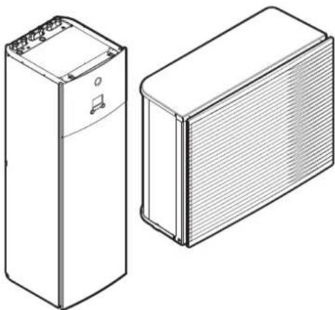
natural_image
Technical line drawing of two rectangular electronic devices, one cylindrical and one rectangular, with no visible text or symbols.https://daikintechnicaldatahub.eu
EPRA14DAV3
EPRA16DAV3
EPRA18DAV3
EPRA14DAW1
EPRA16DAW1
EPRA18DAW1
ETVH16S18DA6V(G)
ETVH16S23DA6V(G)
ETVH16S18DA9W(G)
ETVH16S23DA9W(G)
ETVX16S18DA6V(G)
ETVX16S23DA6V(G)
ETVX16S18DA9W(G)
ETVX16S23DA9W(G)
Table of contents
1 General safety precautions 6
1.1 About the documentation.... 6
1.1.1 Meaning of warnings and symbols 6
1.2 For the installer 7
1.2.1 General 7
1.2.2 Installation site 8
1.2.3 Refrigerant 9
1.2.4 Brine 10
1.2.5 Water 11
1.2.6 Electrical 11
2 About the documentation 14
2.1 About this document 14
2.2 Installer reference guide at a glance 15
3 About the box 17
3.1 Overview: About the box.... 17
3.2 Outdoor unit 17
3.2.1 To handle the outdoor unit 17
3.2.2 To unpack the outdoor unit 19
3.2.3 To remove the accessories from the outdoor unit 20
3.3 Indoor unit 21
3.3.1 To unpack the indoor unit 21
3.3.2 To remove the accessories from the indoor unit 21
3.3.3 To handle the indoor unit.... 21
4 About the units and options 22
4.1 Overview: About the units and options.... 22
4.2 Identification 22
4.2.1 Identification label: Outdoor unit 22
4.2.2 Identification label: Indoor unit 23
4.3 Combining units and options.... 23
4.3.1 Possible combinations of indoor unit and outdoor unit 23
4.3.2 Possible options for the outdoor unit 24
4.3.3 Possible options for the indoor unit 24
5 Application guidelines 27
5.1 Overview: Application guidelines 27
5.2 Setting up the space heating/cooling system 28
5.2.1 Single room.... 29
5.2.2 Multiple rooms – One LWT zone 33
5.2.3 Multiple rooms – Two LWT zones.... 37
5.3 Setting up an auxiliary heat source for space heating.... 40
5.4 Setting up the domestic hot water tank 43
5.4.1 System layout – Integrated DHW tank 43
5.4.2 Selecting the volume and desired temperature for the DHW tank 43
5.4.3 Setup and configuration – DHW tank 45
5.4.4 DHW pump for instant hot water 45
5.5 Setting up the energy metering.... 46
5.5.1 Produced heat 47
5.5.2 Consumed energy 47
5.5.3 Normal kWh rate power supply 47
5.5.4 Preferential kWh rate power supply 49
5.6 Setting up the power consumption control.... 50
5.6.1 Permanent power limitation 50
5.6.2 Power limitation activated by digital inputs 51
5.6.3 Power limitation process.... 52
5.6.4 BBR16 power limitation.... 53
5.7 Setting up an external temperature sensor 53
6 Unit Installation 55
6.1 Preparing the installation site.... 55
6.1.1 Installation site requirements of the outdoor unit 55
6.1.2 Additional installation site requirements of the outdoor unit in cold climates.... 58
6.1.3 Installation site requirements of the indoor unit 58
6.2 Opening and closing the units 59
6.2.1 About opening the units.... 59
6.2.2 To open the outdoor unit 59
6.2.3 To remove the transportation stay 60
6.2.4 To close the outdoor unit 60
6.2.5 To open the indoor unit 61
6.2.6 To lower the switch box on the indoor unit 63
6.2.7 To close the indoor unit 64
6.3 Mounting the outdoor unit 64
6.3.1 About mounting the outdoor unit 64
6.3.2 Precautions when mounting the outdoor unit 64
6.3.3 To provide the installation structure 64
6.3.4 To install the outdoor unit 65
6.3.5 To provide drainage.... 66
6.3.6 To install the discharge grille.... 68
6.3.7 To remove the discharge grille, and put the grille in safety position.... 69
6.4 Mounting the indoor unit 71
6.4.1 About mounting the indoor unit.... 71
6.4.2 Precautions when mounting the indoor unit.... 71
6.4.3 To install the indoor unit 71
6.4.4 To connect the drain hose to the drain 72
7 Piping installation 74
7.1 Preparing water piping 74
7.1.1 Water circuit requirements.... 74
7.1.2 Formula to calculate the expansion vessel pre-pressure 76
7.1.3 To check the water volume and flow rate 76
7.1.4 Changing the pre-pressure of the expansion vessel.... 79
7.1.5 To check the water volume: Examples 79
7.2 Connecting water piping.... 80
7.2.1 About connecting the water piping 80
7.2.2 Precautions when connecting the water piping.... 80
7.2.3 To connect the water piping 80
7.2.4 To connect the recirculation piping.... 82
7.2.5 To fill the water circuit 83
7.2.6 To protect the water circuit against freezing 83
7.2.7 To fill the domestic hot water tank 86
7.2.8 To insulate the water piping 86
8 Electrical installation 88
8.1 About connecting the electrical wiring 88
8.1.1 Precautions when connecting the electrical wiring.... 88
8.1.2 Guidelines when connecting the electrical wiring.... 89
8.1.3 About electrical compliance.... 90
8.1.4 About preferential kWh rate power supply 90
8.1.5 Overview of electrical connections except external actuators 91
8.2 Connections to the outdoor unit 92
8.2.1 To connect the electrical wiring to the outdoor unit 92
8.2.2 To reposition the air thermistor on the outdoor unit 98
8.3 Connections to the indoor unit 99
8.3.1 To connect the main power supply.... 102
8.3.2 To connect the backup heater power supply 104
8.3.3 To connect the shut-off valve 106
8.3.4 To connect the electricity meters.... 107
8.3.5 To connect the domestic hot water pump 108
8.3.6 To connect the alarm output 109
8.3.7 To connect the space cooling/heating ON/OFF output.... 110
8.3.8 To connect the changeover to external heat source.... 111
8.3.9 To connect the power consumption digital inputs 112
8.3.10 To connect the safety thermostat (normally closed contact).... 113
8.4 After connecting the electrical wiring to the indoor unit 114
9 Configuration 116
9.1 Overview: Configuration.... 116
9.1.1 To access the most used commands 117
9.2 Configuration wizard.... 119
9.3 Possible screens.... 120
9.3.1 Possible screens: Overview 120
9.3.2 Home screen.... 121
9.3.3 Main menu screen.... 124
9.3.4 Menu screen 125
9.3.5 Setpoint screen 125
9.3.6 Detailed screen with values 126
9.3.7 Schedule screen: Example 126
9.4 Weather-dependent curve 130
9.4.1 What is a weather-dependent curve? 130
9.4.2 2-points curve....131
9.4.3 Slope-offset curve.... 132
9.4.4 Using weather-dependent curves.... 133
9.5 Settings menu 135
9.5.1 Malfunctioning 135
9.5.2 Room 136
9.5.3 Main zone 140
9.5.4 Additional zone 149
9.5.5 Space heating/cooling 155
9.5.6 Tank 163
9.5.7 User settings 170
9.5.8 Information 175
9.5.9 Installer settings 176
9.5.10 Commissioning 194
9.5.11 Operation.... 194
9.5.12 WLAN adapter 195
9.6 Menu structure: Overview user settings.... 197
9.7 Menu structure: Overview installer settings.... 198
10 Commissioning 199
10.1 Overview: Commissioning 199
10.2 Precautions when commissioning.... 200
10.3 Checklist before commissioning.... 200
10.4 Checklist during commissioning 201
10.4.1 Minimum flow rate 201
10.4.2 Air purge function.... 201
10.4.3 Operation test run 203
10.4.4 Actuator test run 204
10.4.5 Underfloor heating screed dryout 205
11 Hand-over to the user 209
12 Maintenance and service 210
12.1 Overview: Maintenance and service 210
12.2 Maintenance safety precautions 210
12.3 Yearly maintenance 211
12.3.1 Yearly maintenance outdoor unit: overview 211
12.3.2 Yearly maintenance outdoor unit: instructions.... 211
12.3.3 Yearly maintenance indoor unit: overview 211
12.3.4 Yearly maintenance indoor unit: instructions 211
12.4 To drain the domestic hot water tank 214
12.5 About cleaning the water filter in case of trouble 214
12.5.1 To remove the water filter 215
12.5.2 To clean the water filter in case of trouble.... 215
12.5.3 To install the water filter 216
13 Troubleshooting 218
13.1 Overview: Troubleshooting 218
13.2 Precautions when troubleshooting 218
13.3 Solving problems based on symptoms 219
13.3.1 Symptom: The unit is NOT heating or cooling as expected.... 219
13.3.2 Symptom: Hot water does NOT reach the desired temperature.... 220
13.3.3 Symptom: The compressor does NOT start (space heating or domestic water heating) 220
13.3.4 Symptom: The system is making gurgling noises after commissioning.... 220
13.3.5 Symptom: The pump is blocked.... 221
13.3.6 Symptom: The pump is making noise (cavitation).... 221
13.3.7 Symptom: The pressure relief valve opens 222
13.3.8 Symptom: The water pressure relief valve leaks 222
13.3.9 Symptom: The space is NOT sufficiently heated at low outdoor temperatures.... 223
13.3.10 Symptom: The pressure at the tapping point is temporarily unusually high.... 224
13.3.11 Symptom: Tank disinfection function is NOT completed correctly (AH-error) 224
13.4 Solving problems based on error codes 224
13.4.1 To display the help text in case of a malfunction 224
13.4.2 Error codes: Overview 225
14 Disposal 229
14.1 To recover refrigerant.... 229
15 Technical data 231
15.1 Service space: Outdoor unit 232
15.2 Piping diagram: Outdoor unit 233
15.3 Piping diagram: Indoor unit 234
15.4 Wiring diagram: Outdoor unit 235
15.5 Wiring diagram: Indoor unit 240
16 Glossary 246
17 Field settings table 247
1 General safety precautions
In this chapter
1.1 About the documentation.... 6
1.1.1 Meaning of warnings and symbols 6
1.2 For the installer 7
1.2.1 General 7
1.2.2 Installation site 8
1.2.3 Refrigerant 9
1.2.4 Brine 10
1.2.5 Water 11
1.2.6 Electrical 11
1.1 About the documentation
- The original documentation is written in English. All other languages are translations.
- The precautions described in this document cover very important topics, follow them carefully.
- The installation of the system, and all activities described in the installation manual and in the installer reference guide MUST be performed by an authorised installer.
1.1.1 Meaning of warnings and symbols

DANGER
Indicates a situation that results in death or serious injury.

DANGER: RISK OF ELECTROCUTION
Indicates a situation that could result in electrocution.

DANGER: RISK OF BURNING
Indicates a situation that could result in burning because of extreme hot or cold temperatures.

DANGER: RISK OF EXPLOSION
Indicates a situation that could result in explosion.

WARNING
Indicates a situation that could result in death or serious injury.

WARNING: FLAMMABLE MATERIAL

CAUTION
Indicates a situation that could result in minor or moderate injury.

NOTICE
Indicates a situation that could result in equipment or property damage.

INFORMATION
Indicates useful tips or additional information.
Symbols used on the unit:
| Symbol Explanation | |
 | Before installation, read the installation and operation manual, and the wiring instruction sheet. |
 | Before performing maintenance and service tasks, read the service manual. |
 | For more information, see the installer and user reference guide. |
 | The unit contains rotating parts. Be careful when servicing or inspecting the unit. |
Symbols used in the documentation:
| Symbol Explanation | |
| Indicates a figure title or a reference to it.Example: "1-3 Figure title" means "Figure 3 in chapter 1". | |
| Indicates a table title or a reference to it.Example: "1-3 Table title" means "Table 3 in chapter 1". | |
1.2 For the installer
1.2.1 General
If you are NOT sure how to install or operate the unit, contact your dealer.

DANGER: RISK OF BURNING
- Do NOT touch the refrigerant piping, water piping or internal parts during and immediately after operation. It could be too hot or too cold. Give it time to return to normal temperature. If you must touch it, wear protective gloves.
- Do NOT touch any accidental leaking refrigerant.

WARNING
Improper installation or attachment of equipment or accessories could result in electrical shock, short-circuit, leaks, fire or other damage to the equipment. Only use accessories, optional equipment and spare parts made or approved by Daikin.

WARNING
Make sure installation, testing and applied materials comply with applicable legislation (on top of the instructions described in the Daikin documentation).

CAUTION
Wear adequate personal protective equipment (protective gloves, safety glasses,...) when installing, maintaining or servicing the system.

WARNING
Tear apart and throw away plastic packaging bags so that nobody, especially children, can play with them. Possible risk: suffocation.

WARNING
Provide adequate measures to prevent that the unit can be used as a shelter by small animals. Small animals that make contact with electrical parts can cause malfunctions, smoke or fire.

CAUTION
Do NOT touch the air inlet or aluminium fins of the unit.

CAUTION
Do NOT place any objects or equipment on top of the unit.
Do NOT sit, climb or stand on the unit.

NOTICE
Works executed on the outdoor unit are best done under dry weather conditions to avoid water ingress.
In accordance with the applicable legislation, it might be necessary to provide a logbook with the product containing at least: information on maintenance, repair work, results of tests, stand-by periods,...
Also, at least, following information MUST be provided at an accessible place at the product:
- Instructions for shutting down the system in case of an emergency
■ Name and address of fire department, police and hospital - Name, address and day and night telephone numbers for obtaining service
In Europe, EN378 provides the necessary guidance for this logbook.
1.2.2 Installation site
- Provide sufficient space around the unit for servicing and air circulation.
- Make sure the installation site withstands the weight and vibration of the unit.
- Make sure the area is well ventilated. Do NOT block any ventilation openings.
■ Make sure the unit is level.
Do NOT install the unit in the following places: - In potentially explosive atmospheres.
- In places where there is machinery that emits electromagnetic waves. Electromagnetic waves may disturb the control system, and cause malfunction of the equipment.
- In places where there is a risk of fire due to the leakage of flammable gases (example: thinner or gasoline), carbon fibre, ignitable dust.
- In places where corrosive gas (example: sulphurous acid gas) is produced. Corrosion of copper pipes or soldered parts may cause the refrigerant to leak.
1.2.3 Refrigerant
If applicable. See the installation manual or installer reference guide of your application for more information.

NOTICE
Make sure refrigerant piping installation complies with applicable legislation. In Europe, EN378 is the applicable standard.

NOTICE
Make sure the field piping and connections are NOT subjected to stress.

WARNING
During tests, NEVER pressurize the product with a pressure higher than the maximum allowable pressure (as indicated on the nameplate of the unit).

WARNING
Take sufficient precautions in case of refrigerant leakage. If refrigerant gas leaks, ventilate the area immediately. Possible risks:
- Excessive refrigerant concentrations in a closed room can lead to oxygen deficiency.
In case of R410A or R32 refrigerant: Toxic gas might be produced if refrigerant gas comes into contact with fire.
In case of CO_2 refrigerant: Refrigerant gas is toxic in high concentrations.

DANGER: RISK OF EXPLOSION
Pump down – Refrigerant leakage. If you want to pump down the system, and there is a leak in the refrigerant circuit:
- Do NOT use the unit's automatic pump down function, with which you can collect all refrigerant from the system into the outdoor unit. Possible consequence: Self-combustion and explosion of the compressor because of air going into the operating compressor.
- Use a separate recovery system so that the unit's compressor does NOT have to operate.

WARNING
ALWAYS recover the refrigerant. Do NOT release them directly into the environment. Use a vacuum pump to evacuate the installation.

NOTICE
After all the piping has been connected, make sure there is no gas leak. Use nitrogen to perform a gas leak detection.

NOTICE
- To avoid compressor breakdown, do NOT charge more than the specified amount of refrigerant.
- When the refrigerant system is to be opened, refrigerant MUST be treated according to the applicable legislation.

WARNING
Make sure there is no oxygen in the system. Refrigerant may only be charged after performing the leak test and the vacuum drying.
Possible consequence: Self-combustion and explosion of the compressor because of oxygen going into the operating compressor.
- In case recharge is required, see the nameplate of the unit. It states the type of refrigerant and necessary amount.
- The unit is factory charged with refrigerant and depending on pipe sizes and pipe lengths some systems require additional charging of refrigerant.
- Only use tools exclusively for the refrigerant type used in the system, this to ensure pressure resistance and prevent foreign materials from entering into the system.
- Charge the liquid refrigerant as follows:
| If Then | |
| A siphon tube is present(i.e., the cylinder is marked with "Liquid filling siphon attached") | Charge with the cylinder upright.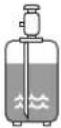 |
| A siphon tube is NOT present Charge with | the cylinder upside down. |
- Open refrigerant cylinders slowly.
- Charge the refrigerant in liquid form. Adding it in gas form may prevent normal operation.

CAUTION
When the refrigerant charging procedure is done or when pausing, close the valve of the refrigerant tank immediately. If the valve is NOT closed immediately, remaining pressure might charge additional refrigerant. Possible consequence: Incorrect refrigerant amount.
1.2.4 Brine
If applicable. See the installation manual or installer reference guide of your application for more information.

WARNING
The selection of the brine MUST be in accordance with the applicable legislation.

WARNING
Take sufficient precautions in case of brine leakage. If brine leaks, ventilate the area immediately and contact your local dealer.

WARNING
The ambient temperature inside the unit can get much higher than that of the room, e.g. 70°C. In case of a brine leak, hot parts inside the unit can create a hazardous situation.

WARNING
The use and installation of the application MUST comply with the safety and environmental precautions specified in the applicable legislation.
1.2.5 Water
If applicable. See the installation manual or installer reference guide of your application for more information.

NOTICE
Make sure water quality complies with EU directive 98/83 EC.
1.2.6 Electrical

DANGER: RISK OF ELECTROCUTION
- Turn OFF all power supply before removing the switch box cover, connecting electrical wiring or touching electrical parts.
- Disconnect the power supply for more than 1 minute, and measure the voltage at the terminals of main circuit capacitors or electrical components before servicing. The voltage MUST be less than 50 V DC before you can touch electrical components. For the location of the terminals, see the wiring diagram.
- Do NOT touch electrical components with wet hands.
- Do NOT leave the unit unattended when the service cover is removed.

WARNING
If NOT factory installed, a main switch or other means for disconnection, having a contact separation in all poles providing full disconnection under overvoltage category III condition, MUST be installed in the fixed wiring.

WARNING
ONLY use copper wires.
- Make sure the field wiring complies with the applicable legislation.
- All field wiring MUST be performed in accordance with the wiring diagram supplied with the product.
- NEVER squeeze bundled cables and make sure they do NOT come in contact with the piping and sharp edges. Make sure no external pressure is applied to the terminal connections.
■ Make sure to install earth wiring. Do NOT earth the unit to a utility pipe, surge absorber, or telephone earth. Incomplete earth may cause electrical shock.
- Make sure to use a dedicated power circuit. NEVER use a power supply shared by another appliance.
■ Make sure to install the required fuses or circuit breakers.
- Make sure to install an earth leakage protector. Failure to do so may cause electrical shock or fire.
- When installing the earth leakage protector, make sure it is compatible with the inverter (resistant to high frequency electric noise) to avoid unnecessary opening of the earth leakage protector.

CAUTION
- When connecting the power supply: connect the earth cable first, before making the current-carrying connections.
- When disconnecting the power supply: disconnect the current-carrying cables first, before separating the earth connection.
- The length of the conductors between the power supply stress relief and the terminal block itself must be as such that the current-carrying wires are tautened before the earth wire is in case the power supply is pulled loose from the stress relief.

NOTICE
Precautions when laying power wiring:
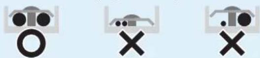
- Do NOT connect wiring of different thicknesses to the power terminal block (slack in the power wiring may cause abnormal heat).
- When connecting wiring which is the same thickness, do as shown in the figure above.
- For wiring, use the designated power wire and connect firmly, then secure to prevent outside pressure being exerted on the terminal board.
- Use an appropriate screwdriver for tightening the terminal screws. A screwdriver with a small head will damage the head and make proper tightening impossible.
- Over-tightening the terminal screws may break them.
Install power cables at least 1 m away from televisions or radios to prevent interference. Depending on the radio waves, a distance of 1 m may not be sufficient.

WARNING
- After finishing the electrical work, confirm that each electrical component and terminal inside the electrical components box is connected securely.
■ Make sure all covers are closed before starting up the unit.

NOTICE
Only applicable if the power supply is three-phase, and the compressor has an ON/OFF starting method.
If there exists the possibility of reversed phase after a momentary black out and the power goes on and off while the product is operating, attach a reversed phase protection circuit locally. Running the product in reversed phase can break the compressor and other parts.
2 About the documentation
In this chapter
2.1 About this document.... 14
2.2 Installer reference guide at a glance 15
2.1 About this document
Target audience
Authorised installers
Documentation set
This document is part of a documentation set. The complete set consists of:
■ General safety precautions:
- Safety instructions that you must read before installing
- Format: Paper (in the box of the indoor unit)
- Operation manual:
- Quick guide for basic usage
- Format: Paper (in the box of the indoor unit)
- User reference guide:
- Detailed step-by-step instructions and background information for basic and advanced usage
- Format: Digital files on http://www.daikineurope.com/support-and-manuals/product-information/
- Installation manual – Outdoor unit:
- Installation instructions
- Format: Paper (in the box of the outdoor unit)
- Installation manual – Indoor unit:
- Installation instructions
- Format: Paper (in the box of the indoor unit)
- Installer reference guide:
- Preparation of the installation, good practices, reference data, ...
- Format: Digital files on http://www.daikineurope.com/support-and-manuals/product-information/
- Addendum book for optional equipment:
- Additional info about how to install optional equipment
- Format: Paper (in the box of the indoor unit) + Digital files on http://www.daikineurope.com/support-and-manuals/product-information/
Latest revisions of the supplied documentation may be available on the regional Daikin website or via your dealer.
The original documentation is written in English. All other languages are translations.
Technical engineering data
- A subset of the latest technical data is available on the regional Daikin website (publicly accessible).
- The full set of latest technical data is available on the Daikin Business Portal (authentication required).
Online tools
In addition to the documentation set, some online tools are available for installers:
- Daikin Technical Data Hub
- Central hub for technical specifications of the unit, useful tools, digital resources, and more.
- Publicly accessible via https://daikintechnicaldatahub.eu.
■ Heating Solutions Navigator
- Digital toolbox that offers a variety of tools to facilitate the installation and configuration of heating systems.
- To access Heating Solutions Navigator, registration to the Stand By Me platform is required. For more information, see https://professional.standbyme.daikin.eu.
- Daikin e-Care
- Mobile app for installers and service technicians that allows you to register, configure and troubleshoot heating systems.
- The mobile app can be downloaded for iOS and Android devices using the QR codes below. Registration to the Stand By Me platform is required to access the app.
App Store Google Play

2.2 Installer reference guide at a glance
| Chapter Description | |
| General safety precautions Safety | instructions that you must read before installing |
| About the documentation What | documentation exists for the installer |
| About the box How to unpack the | units and remove their accessories |
| About the units and options | How to identify the unitsPossible combinations of units and options |
| Application guidelines | Various installation setups of the system |
| Unit installation | What to do and know to install the system, including information on how to prepare for an installation |
2 | About the documentation
| Chapter Description | |
| Piping installation What to do and | know to install the piping of the system, including information on how to prepare for an installation |
| Electrical installation What to do | and know to install the electrical components of the system, including information on how to prepare for an installation |
| Configuration What to do and know to configure the system after it is installed | |
| Commissioning What to do and know to commission the system after it is configured | |
| Hand-over to the user What to give and explain to the user | |
| Maintenance and service How to maintain and service the units | |
| Troubleshooting What to do in case of problems | |
| Disposal How to dispose of the system | |
| Technical data Specifications of the system | |
| Glossary Definition of terms | |
| Field settings table Table to be filled in by the installer, and kept for future referenceNote: There is also an installer settings table in the user reference guide. This table has to be filled in by the installer and handed over to the user. | |
3 About the box
In this chapter
3.1 Overview: About the box.... 17
3.2 Outdoor unit 17
3.2.1 To handle the outdoor unit 17
3.2.2 To unpack the outdoor unit 19
3.2.3 To remove the accessories from the outdoor unit 20
3.3 Indoor unit 21
3.3.1 To unpack the indoor unit 21
3.3.2 To remove the accessories from the indoor unit 21
3.3.3 To handle the indoor unit 21
3.1 Overview: About the box
This chapter describes what you have to do after the boxes with the outdoor and indoor unit are delivered on-site.
Keep the following in mind:
- At delivery, the unit MUST be checked for damage. Any damage MUST be reported immediately to the claims agent of the carrier.
- Bring the packed unit as close as possible to its final installation position to prevent damage during transport.
- Prepare the path along which you want to bring the unit inside in advance.
3.2 Outdoor unit
3.2.1 To handle the outdoor unit

CAUTION
To avoid injury, do NOT touch the air inlet or aluminium fins of the unit.
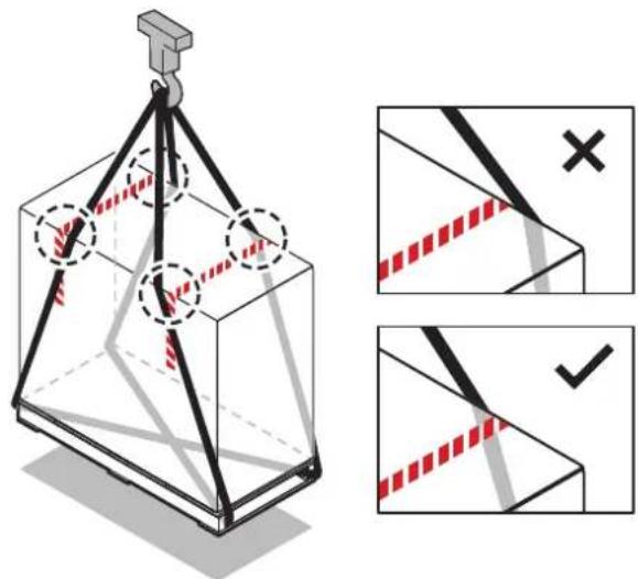
Crane
Keep the slings within the marked area to not damage the unit.
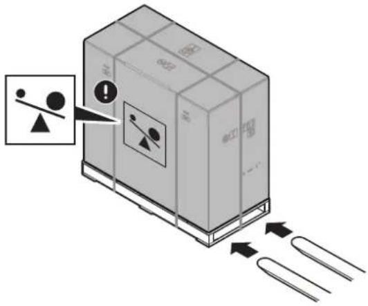
Forklift or pallet truck
Enter the pallet from the heavy side.
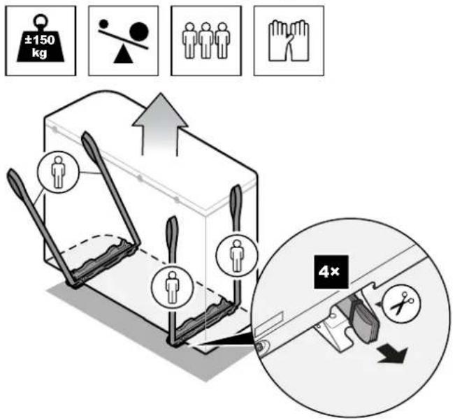
3 persons
After unpacking, carry the unit using the slings attached to the unit.
See also:
- "3.2.2 To unpack the outdoor unit" [▶ 19]
- "6.3.4 To install the outdoor unit" [▶ 65]
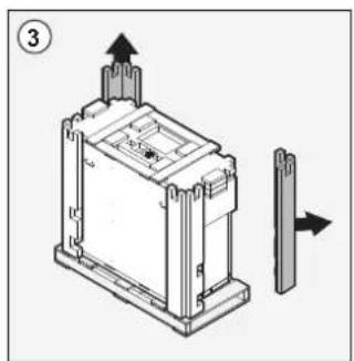
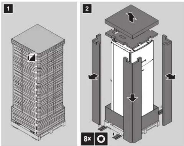
3.2.2 To unpack the outdoor unit
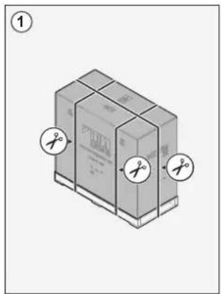
natural_image
Isometric illustration of a box with scissors cutting through it, no text or symbols present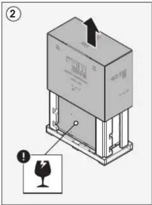
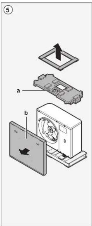
a, b Accessories
3.2.3 To remove the accessories from the outdoor unit
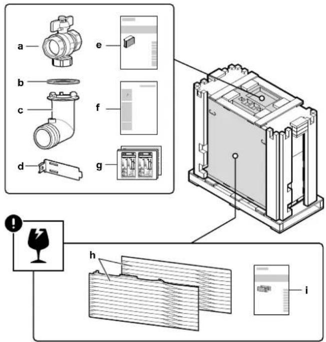
a Shut-off valve (with integrated filter)
b O-ring for drain socket
c Drain socket
d Thermistor fixture (for installations in areas with low ambient temperatures)
e Installation manual – Outdoor unit
f Disposal manual – Recovering refrigerant
g Energy label
h Discharge grille (upper + lower part)
i Installation manual – Discharge grille

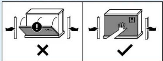
NOTICE
Unpacking – Front corners. When you remove the front packaging corners, hold the box containing the discharge grille to prevent it from falling.
3.3 Indoor unit
3.3.1 To unpack the indoor unit
3.3.2 To remove the accessories from the indoor unit
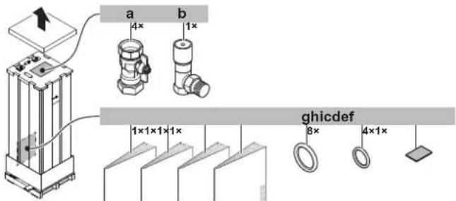
a Shut-off valves for water circuit
b Overpressure bypass valve
c General safety precautions
d Addendum book for optional equipment
e Indoor unit installation manual
f Operation manual
g Sealing rings for shut-off valves (space heating water circuit)
h Sealing rings for field-supplied shut-off valves (domestic hot water circuit)
Sealing tape for low voltage wiring intake
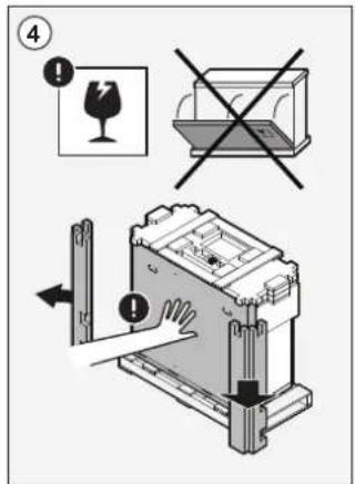
3.3.3 To handle the indoor unit
Use the handles at the back and at the bottom to carry the unit.
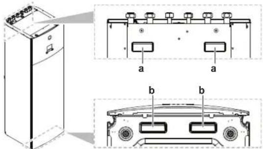
a Handles at the back of the unit
b Handles at the bottom of the unit. Carefully tilt the unit to the back so that the handles become visible.
4 About the units and options
In this chapter
4.1 Overview: About the units and options 22
4.2 Identification.... 22
4.2.1 Identification label: Outdoor unit 22
4.2.2 Identification label: Indoor unit 23
4.3 Combining units and options.... 23
4.3.1 Possible combinations of indoor unit and outdoor unit 23
4.3.2 Possible options for the outdoor unit.... 24
4.3.3 Possible options for the indoor unit 24
4.1 Overview: About the units and options
This chapter contains information about:
■ Identifying the outdoor unit
■ Identifying the indoor unit
- Combining the outdoor unit with options
- Combining the indoor unit with options
4.2 Identification

NOTICE
When installing or servicing several units at the same time, make sure NOT to switch the service panels between different models.
4.2.1 Identification label: Outdoor unit
Location
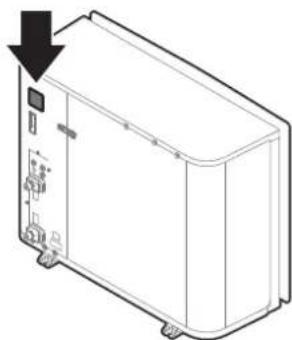
natural_image
Line drawing of a rectangular electronic device with a black arrow pointing to its top panel (no text or symbols present)Model identification
Example: EP R A 14 DA V3
| Code Explanation | |
| EP European hydro-split outdoor pair heat pump | |
| R High water temperature – ambient zone 2 (see operation range) | |
| A Refrigerant R32 | |
| 14 Capacity class | |
| DA Model series | |
| V3 Power supply | |
4.2.2 Identification label: Indoor unit
Location
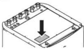
natural_image
Diagram of a mechanical component with a downward arrow indicating a specific part (no text or symbols present)Model identification
Example: E TV H 16 S 23 DA 6V G
| Code Description | |
| E European model | |
| TV Floor-standing hydro-split unit with integrated tank | |
| H H=Heating only | X=Heating/cooling |
| 16 Capacity class | |
| S Integrated tank material: Stainless steel | |
| 23 Integrated tank volume | |
| DA Model series | |
| 6V Backup heater model | |
| G G=Grey model | [—]=White model |
4.3 Combining units and options

INFORMATION
Certain options might not be available in your country.
4.3.1 Possible combinations of indoor unit and outdoor unit
| Indoor unit Outdoor unit | |||
| EPRA14 EPRA16 EPRA18 | |||
| ETVH/X16 O O O | |||
4.3.2 Possible options for the outdoor unit
Mounting stand (EKMST1, EKMST2)
In colder regions where heavy snowfall can occur, it is recommended to install the outdoor unit on a mounting frame. Use one of the following models:
- EKMST1 with flange feet: to install the outdoor unit on a concrete foundation where drilling is allowed.
- EKMST2 with rubber feet: to install the outdoor unit on foundations where drilling is not allowed or possible, such as flat roofs or pavements.
For installation instructions, see the installation manual of the mounting stand.
4.3.3 Possible options for the indoor unit
Multi-zoning wired controls
You can connect the following multi-zoning wired controls:
■ Multi-zoning base unit 230 V (EKWUFHTA1V3)
■ Digital thermostat 230 V (EKWCTRDI1V3)
- Analogue thermostat 230 V (EKWCTRAN1V3)
- Actuator 230 V (EKWCVATR1V3)
For installation instructions, see the installation manual of the control, and the addendum book for optional equipment.
Wireless room thermostat (EKRTR1)
You can connect an optional wireless room thermostat to the indoor unit.
For installation instructions, see the installation manual of the room thermostat and addendum book for optional equipment.
Remote sensor for wireless thermostat (EKRTETS)
You can use a wireless indoor temperature sensor (EKRTETS) only in combination with the wireless thermostat (EKRTR1).
For installation instructions, see the installation manual of the room thermostat and addendum book for optional equipment.
Digital I/O PCB (EKRP1HBAA)
The digital I/O PCB is required to provide following signals:
- Alarm output
■ Space heating/cooling On/OFF output - Changeover to external heat source
For installation instructions, see the installation manual of the digital I/O PCB and addendum book for optional equipment.
Demand PCB (EKRP1AHTA)
To enable the power saving consumption control by digital inputs you must install the demand PCB.
For installation instructions, see the installation manual of the demand PCB and addendum book for optional equipment.
Remote indoor sensor (KRCS01-1)
By default the internal sensor of the dedicated Human Comfort Interface (BRC1HHDA used as room thermostat) will be used as room temperature sensor.
As an option the remote indoor sensor can be installed to measure the room temperature on another location.
For installation instructions, see the installation manual of the remote indoor sensor and addendum book for optional equipment.

INFORMATION
- The remote indoor sensor can only be used in case the user interface is configured with room thermostat functionality.
- You can only connect either the remote indoor sensor or the remote outdoor sensor.
Remote outdoor sensor (EKRSCA1)
By default the sensor inside the outdoor unit will be used to measure the outdoor temperature.
As an option the remote outdoor sensor can be installed to measure the outdoor temperature on another location (e.g. to avoid direct sunlight) to have an improved system behaviour.
For installation instructions, see the installation manual of the remote outdoor sensor and the addendum book for optional equipment.

INFORMATION
You can only connect either the remote indoor sensor or the remote outdoor sensor.
PC cable (EKPCCAB4)
The PC cable makes a connection between the switch box of the indoor unit and a PC. It gives the possibility to update the software of the indoor unit.
For installation instructions, see the installation manual of the PC cable.
Heat pump convector (FWXV, FWXT, FWXM)
For providing space heating/cooling, it is possible to use the following heat pump convectors:
■ FWXV: floor-standing model
■ FWXT: wall-mounted model
- FWXM: concealed model
For installation instructions, see:
- The installation manual of the heat pump convectors
- The installation manual of the heat pump convector options
- The addendum book for optional equipment
LAN adapter for smartphone control + Smart Grid applications (BRP069A61)
You can install this LAN adapter to:
■ Control the system via a smartphone app.
- Use the system in various Smart Grid applications.
For installation instructions, see the installation manual of the LAN adapter and the addendum book for optional equipment.
LAN adapter for smartphone control (BRP069A62)
You can install this LAN adapter to control the system via a smartphone app.
For installation instructions, see the installation manual of the LAN adapter and the addendum book for optional equipment.
WLAN adapter (BRP069A71)
You can install the wireless LAN adapter to control the system via a smartphone app.
For installation instructions, see the installation manual of the WLAN adapter and the addendum book for optional equipment.
Universal centralised controller (EKCC8-W)
Controller for cascade control.
Bizone kit (BZKA7V3)
You can install an optional bizone kit.
For installation instructions, see the installation manual of the bizone kit.
Conversion kit (EKHVCONV2)
Use the connection kit to convert a heating only model to a reversible model.
For installation instructions, see the installation manual of the conversion kit.
Human Comfort Interface (BRC1HHDA) used as room thermostat
- The Human Comfort Interface (HCI) used as room thermostat can only be used in combination with the user interface connected to the indoor unit.
- The Human Comfort Interface (HCI) used as room thermostat needs to be installed in the room that you want to control.
For installation instructions, see the installation and operation manual of the Human Comfort Interface (HCI) as room thermostat.
5 Application guidelines

INFORMATION
Cooling is only applicable in case of:
■ Reversible models
Heating only models + conversion kit (EKHVCONV2)
In this chapter
5.1 Overview: Application guidelines.... 27
5.2 Setting up the space heating/cooling system 28
5.2.1 Single room.... 29
5.2.2 Multiple rooms – One LWT zone 33
5.2.3 Multiple rooms – Two LWT zones 37
5.3 Setting up an auxiliary heat source for space heating.... 40
5.4 Setting up the domestic hot water tank 43
5.4.1 System layout – Integrated DHW tank 43
5.4.2 Selecting the volume and desired temperature for the DHW tank 43
5.4.3 Setup and configuration – DHW tank 45
5.4.4 DHW pump for instant hot water 45
5.4.5 DHW pump for disinfection 46
5.5 Setting up the energy metering 46
5.5.1 Produced heat 47
5.5.2 Consumed energy 47
5.5.3 Normal kWh rate power supply 47
5.5.4 Preferential kWh rate power supply 49
5.6 Setting up the power consumption control 50
5.6.1 Permanent power limitation 50
5.6.2 Power limitation activated by digital inputs 51
5.6.3 Power limitation process 52
5.6.4 BBR16 power limitation 53
5.7 Setting up an external temperature sensor.... 53
5.1 Overview: Application guidelines
The purpose of the application guidelines is to give a glance of the possibilities of the heat pump system.

NOTICE
- The illustrations in the application guidelines are meant for reference only, and are NOT to be used as detailed hydraulic diagrams. The detailed hydraulic dimensioning and balancing are NOT shown, and are the responsibility of the installer.
- For more information about the configuration settings to optimize heat pump operation, see "9 Configuration" [▶ 116].
This chapter contains application guidelines for:
- Setting up the space heating/cooling system
- Setting up an auxiliary heat source for space heating
- Setting up the domestic hot water tank
- Setting up the energy metering
- Setting up the power consumption control
- Setting up an external temperature sensor

NOTICE
Certain types of fan coil units – in this document referred to as "heat pump convectors"-, are able to receive input of the indoor unit operation mode (cooling or heating X2M/3 and X2M/4) and/or to send output of the heat pump convector thermostatic condition (main zone: X2M/30 and X2M/35; additional zone: X2M/30 and X2M/35a).
The application guidelines illustrate the possibility of receiving or sending digital input/output. This functionality can only be used in case the heat pump convector has such features and the signals meet following requirements:
- Output of indoor unit (input to heat pump convector): cooling/heating signal=230 V (cooling=230 V, heating=0 V).
- Input to indoor unit (output of heat pump convector): thermostat ON/OFF signal=voltage-free contact (closed contact=thermo ON, open contact=thermo OFF).
5.2 Setting up the space heating/cooling system
The heat pump system supplies leaving water to heat emitters in one or more rooms.
Because the system offers a wide flexibility to control the temperature in each room, you need to answer the following questions first:
How many rooms are heated or cooled by the heat pump system?
- Which heat emitter types are used in each room and what is their design leaving water temperature?
Once the space heating/cooling requirements are clear, we recommend to follow the setup guidelines below.

NOTICE
If an external room thermostat is used, the external room thermostat will control the room frost protection. However, the room frost protection is only possible if [C.2] Space heating/cooling=On.

INFORMATION
In case an external room thermostat is used and room frost protection needs to be guaranteed in all conditions, then you have to set Emergency [9.5] to Automatic.

NOTICE
An overpressure bypass valve can be integrated in the system. Keep in mind that this valve might not be shown on the illustrations.
5.2.1 Single room
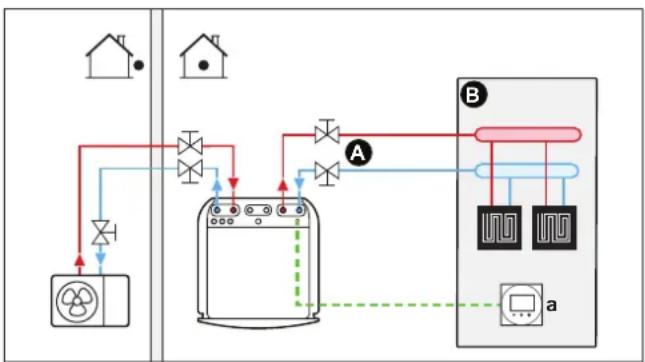
Underfloor heating or radiators – Wired room thermostat
Setup
flowchart
graph TD
    A["Fan"] --> B["Reactor"]
    B --> C["Reactor"]
    C --> D["Control Panel"]
    D --> E["Sensor 1"]
    D --> F["Sensor 2"]
    style A fill:#f9f,stroke:#333
    style B fill:#ccf,stroke:#333
    style C fill:#cfc,stroke:#333
    style D fill:#fcc,stroke:#333
    style E fill:#ffc,stroke:#333
    style F fill:#fcc,stroke:#333
A Main leaving water temperature zone
B One single room
a Dedicated Human Comfort Interface (BRC1HHDA used as room thermostat)
- For more information about connecting the electrical wiring to the unit, see:
- "8.2 Connections to the outdoor unit" [▶ 92]
-
"8.3 Connections to the indoor unit" [▶ 99]
-
The underfloor heating or radiators are directly connected to the indoor unit.
- The room temperature is controlled by the dedicated Human Comfort Interface (BRC1HHDA used as room thermostat).
Configuration
| Setting Value | |
| Unit temperature control:• #: [2.9]• Code: [C-07] | 2 (Room thermostat): Unit operation is decided based on the ambient temperature of the dedicated Human Comfort Interface. |
| Number of water temperature zones:• #: [4.4]• Code: [7-02] | 0 (Single zone): Main |
Benefits
- Highest comfort and efficiency. The smart room thermostat functionality can decrease or increase the desired leaving water temperature based on the actual room temperature (modulation). This results in:
- Stable room temperature matching the desired temperature (higher comfort)
- Less ON/OFF cycles (more quiet, higher comfort and higher efficiency)
- Lowest possible leaving water temperature (higher efficiency)
- Easy. You can easily set the desired room temperature via the user interface:
- For your daily needs, you can use preset values and schedules.
- To deviate from your daily needs, you can temporarily overrule the preset values and schedules, or use the holiday mode.
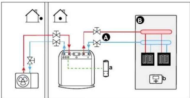
Underfloor heating or radiators – Wireless room thermostat
Setup
flowchart
graph TD
    A["House"] --> B["HVAC"]
    B --> C["Reactor"]
    C --> D["Control Panel"]
    D --> E["Display"]
    D --> F["Control Panel"]
    style A fill:#f9f,stroke:#333
    style B fill:#ccf,stroke:#333
    style C fill:#cfc,stroke:#333
    style D fill:#fcc,stroke:#333
    style E fill:#ffc,stroke:#333
    style F fill:#fcc,stroke:#333
A Main leaving water temperature zone
B One single room
a Receiver for wireless external room thermostat
b Wireless external room thermostat
- For more information about connecting the electrical wiring to the unit, see:
- "8.2 Connections to the outdoor unit" [▶ 92]
-
"8.3 Connections to the indoor unit" [▶ 99]
-
The underfloor heating or radiators are directly connected to the indoor unit.
- The room temperature is controlled by the wireless external room thermostat (optional equipment EKRTR1).
Configuration
| Setting Value | |
| Unit temperature control:• #: [2.9]• Code: [C-07] | 1 (External room thermostat): Unit operation is decided by the external thermostat. |
| Number of water temperature zones:• #: [4.4]• Code: [7-02] | 0 (Single zone): Main |
| External room thermostat for themainzone:• #: [2.A]• Code: [C-05] | 1 (1 contact): When the used external room thermostat or heat pump convector can only send a thermo ON/OFF condition. No separation between heating or cooling demand. |
Benefits
- Wireless. The Daikin external room thermostat is available in a wireless version.
- Efficiency. Although the external room thermostat only sends ON/OFF signals, it is specifically designed for the heat pump system.
- Comfort. In case of underfloor heating, the wireless external room thermostat prevents condensation on the floor during cooling operation by measuring the room humidity.
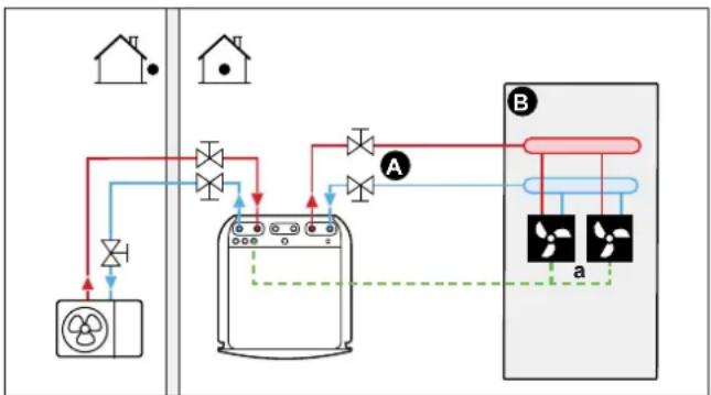
Heat pump convectors
Setup
flowchart
graph TD
    A["Fan"] --> B["Reactor"]
    B --> C["Valve 1"]
    B --> D["Valve 2"]
    C --> E["Air"]
    D --> F["Air"]
    E --> G["Air Inlet"]
    F --> H["Air Inlet"]
    G --> I["Bump"]
    H --> J["Bump"]
    style A fill:#f9f,stroke:#333
    style B fill:#ccf,stroke:#333
    style C fill:#cfc,stroke:#333
    style D fill:#fcc,stroke:#333
    style E fill:#ffc,stroke:#333
    style F fill:#cfc,stroke:#333
    style G fill:#fcc,stroke:#333
    style H fill:#cfc,stroke:#333
    style I fill:#fcc,stroke:#333
A Main leaving water temperature zone
B One single room
a Heat pump convectors (+ controllers)
- For more information about connecting the electrical wiring to the unit, see:
- "8.2 Connections to the outdoor unit" [▶ 92]
- "8.3 Connections to the indoor unit" [▶ 99]
- The heat pump convectors are directly connected to the indoor unit.
- The desired room temperature is set via the controller of the heat pump convectors. There are different controllers and setups possible for the heat pump convectors. For more information, see:
- The installation manual of the heat pump convectors
- The installation manual of the heat pump convector options
- The addendum book for optional equipment
- The space heating/cooling demand signal is sent to one digital input on the indoor unit (X2M/35 and X2M/30).
- The space operation mode is sent to the heat pump convectors by one digital output on the indoor unit (X2M/4 and X2M/3).
Configuration
| Setting Value | |
| Unit temperature control:• #: [2.9]• Code: [C-07] | 1 (External room thermostat): Unit operation is decided by the external thermostat. |
| Number of water temperature zones:• #: [4.4]• Code: [7-02] | 0 (Single zone): Main |
| External room thermostat for the main zone:• #: [2.A]• Code: [C-05] | 1 (1 contact): When the used external room thermostat or heat pump convector can only send a thermo ON/OFF condition. No separation between heating or cooling demand. |
Benefits
- Cooling. The heat pump convector offers, besides heating capacity, also excellent cooling capacity.
- Efficiency. Optimal energy efficiency because of the interlink function.
- Stylish.
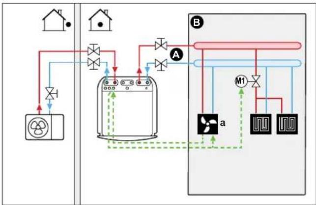
Combination: Underfloor heating + Heat pump convectors
■ Space heating is provided by:
- The underfloor heating
- The heat pump convectors
- Space cooling is provided by the heat pump convectors only. The underfloor heating is shut off by the shut-off valve.
Setup
flowchart
graph TD
    subgraph Left
        A["House Unit"] --> B["Control Unit"]
        B --> C["A"]
        C --> D["B"]
        D --> E["M1"]
        E --> F["a"]
        F --> G["Ground"]
    end
    subgraph Right
        H["House Unit"] --> I["Control Unit"]
        I --> J["A"]
        J --> K["B"]
        K --> L["M1"]
        L --> M["a"]
        M --> N["Ground"]
    end
A Main leaving water temperature zone
B One single room
a Heat pump convectors (+ controllers)
- For more information about connecting the electrical wiring to the unit, see:
- "8.2 Connections to the outdoor unit" [▶ 92]
- "8.3 Connections to the indoor unit" [▶ 99]
- The heat pump convectors are directly connected to the indoor unit.
- A shut-off valve (field supply) is installed before the underfloor heating to prevent condensation on the floor during cooling operation.
- The desired room temperature is set via the controller of the heat pump convectors. There are different controllers and setups possible for the heat pump convectors. For more information, see:
- The installation manual of the heat pump convectors
- The installation manual of the heat pump convector options
- The addendum book for optional equipment
- The space heating/cooling demand signal is sent to one digital input on the indoor unit (X2M/35 and X2M/30).
- The space operation mode is sent by one digital output (X2M/4 and X2M/3) on the indoor unit to:
- The heat pump convectors
- The shut-off valve
Configuration
| Setting Value | |
| Unit temperature control:• #: [2.9]• Code: [C-07] | 1 (External room thermostat): Unit operation is decided by the external thermostat. |
| Number of water temperature zones:▪ #: [4.4]▪ Code: [7-02] | 0 (Single zone): Main |
| External room thermostat for the main zone:▪ #: [2.A]▪ Code: [C-05] | 1 (1 contact): When the used external room thermostat or heat pump convector can only send a thermo ON/OFF condition. No separation between heating or cooling demand. |
Benefits
- Cooling. Heat pump convectors provide, besides heating capacity, also excellent cooling capacity.
- Efficiency. Underfloor heating has the best performance with the heat pump system.
- Comfort. The combination of the two heat emitter types provides:
- The excellent heating comfort of the underfloor heating
- The excellent cooling comfort of the heat pump convectors
5.2.2 Multiple rooms – One LWT zone
If only one leaving water temperature zone is needed because the design leaving water temperature of all heat emitters is the same, you do NOT need a mixing valve station (cost effective).
Example: If the heat pump system is used to heat up one floor where all the rooms have the same heat emitters.
Underfloor heating or radiators – Thermostatic valves
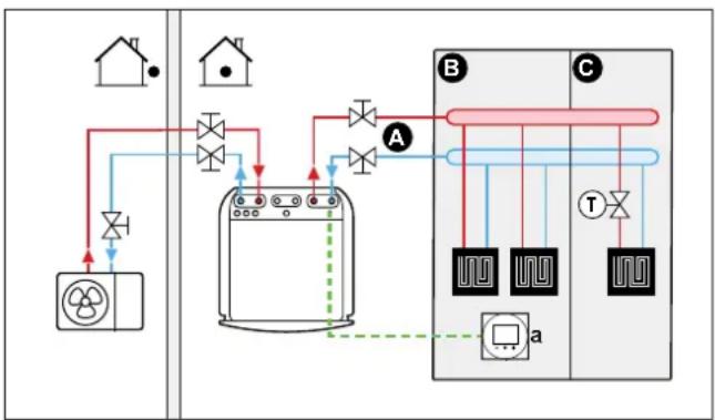
If you are heating up rooms with underfloor heating or radiators, a very common way is to control the temperature of the main room by using a thermostat (this can either be the dedicated Human Comfort Interface (BRC1HHDA) or an external room thermostat), while the other rooms are controlled by so-called thermostatic valves, which open or close depending on the room temperature.
Setup
flowchart
graph TD
    A["House"] --> B["Refrigerator"]
    B --> C["Refrigerator with Valve A"]
    C --> D["Control Panel"]
    D --> E["Refrigerator with Sensor a"]
    D --> F["Control Panel with Sensor T"]
    style A fill:#f9f,stroke:#333
    style B fill:#ccf,stroke:#333
    style C fill:#cfc,stroke:#333
    style D fill:#fcc,stroke:#333
    style E fill:#ffc,stroke:#333
    style F fill:#fcc,stroke:#333
A Main leaving water temperature zone
B Room 1
C Room 2
a Dedicated Human Comfort Interface (BRC1HHDA used as room thermostat)
- For more information about connecting the electrical wiring to the unit, see:
- "8.2 Connections to the outdoor unit" [▶ 92]
- "8.3 Connections to the indoor unit" [▶ 99]
- The underfloor heating of the main room is directly connected to the indoor unit.
- The room temperature of the main room is controlled by the dedicated Human Comfort Interface (BRC1HHDA used as room thermostat).
- A thermostatic valve is installed before the underfloor heating in each of the other rooms.

INFORMATION
Mind situations where the main room can be heated by another heating source. Example: Fireplaces.
Configuration
| Setting Value | |
| Unit temperature control:• #: [2.9]• Code: [C-07] | 2 (Room thermostat): Unit operation is decided based on the ambient temperature of the dedicated Human Comfort Interface. |
| Number of water temperature zones:• #: [4.4]• Code: [7-02] | 0 (Single zone): Main |
Benefits
- Easy. Same installation as for one room, but with thermostatic valves.
Underfloor heating or radiators – Multiple external room thermostats
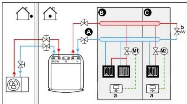
Setup
flowchart
graph TD
    subgraph_House_A["House"]
        direction LR
        A1["Light Bulb"] --> A2["Air Heater"]
        A2 --> A3["Refrigerator"]
        A3 --> A4["Refrigerator"]
        A4 --> A5["Air Heater"]
        A5 --> A6["Air Heater"]
        A6 --> A7["Air Heater"]
        A7 --> A8["Air Heater"]
        A8 --> A9["Air Heater"]
        A9 --> A10["Air Heater"]
        A10 --> A11["Air Heater"]
        A11 --> A12["Air Heater"]
        A12 --> A13["Air Heater"]
        A13 --> A14["Air Heater"]
        A14 --> A15["Air Heater"]
        A15 --> A16["Air Heater"]
        A16 --> A17["Air Heater"]
        A17 --> A18["Air Heater"]
        A18 --> A19["Air Heater"]
        A19 --> A20["Air Heater"]
        A20 --> A21["Air Heater"]
        A21 --> A22["Air Heater"]
        A22 --> A23["Air Heater"]
        A23 --> A24["Air Heater"]
        A24 --> A25["Air Heater"]
        A25 --> A26["Air Heater"]
        A26 --> A27["Air Heater"]
        A27 --> A28["Air Heater"]
        A28 --> A29["Air Heater"]
        A29 --> A30["Air Heater"]
        A30 --> A31["Air Heater"]
        A31 --> A32["Air Heater"]
        A32 --> A33["Air Heater"]
        A33 --> A34["Air Heater"]
        A34 --> A35["Air Heater"]
        A35 --> A36["Air Heater"]
        A36 --> A37["Air Heater"]
        A37 --> A38["Air Heater"]
        A38 --> A39["Air Heater"]
        A39 --> A40["Air Heater"]
        A40 --> A41["Air Heater"]
        A41 --> A42["Air Heater"]
        A42 --> A43["Air Heater"]
        A43 --> A44["Air Heater"]
        A44 --> A45["Air Heater"]
        A45 --> A46["Air Heater"]
        A46 --> A47["Air Heater"]
        A47 --> A48["Air Heater"]
        A48 --> A49["Air Heater"]
        A49 --> A50["Air Heater"]
        A50 --> A51["Air Heater"]
        A51 --> A52["Air Heater"]
        A52 --> A53["Air Heater"]
        A53 --> A54["Air Heater"]
        A54 --> A55["Air Heater"]
        A55 --> A56["Air Heater"]
        A56 --> A57["Air Heater"]
        A57 --> A58["Air Heater"]
        A58 --> A59["Air Heater"]
        A59 --> A60["Air Heater"]
        A60 --> B["B"]
    end
    subgraph Control Panel_Circuit_Circuit_Circuit_Circuit_Circuit_Circuit_Circuit_Circuit_Circuit_Circuit_Circuit_Circuit_Circuit_Circuit_Circuit_Circuit_Circuit_Circuit_Circuit_Circuit_Circuit_Circuit_Circuit_Circuit_Circuit_Circuit_Circuit_Circuit_Circuit_Circuit_Circuit_Circuit_Circuit_Circuit_Circuit_Circuit_Circuit_Circuit_Circuit_Circuit_Circuit_Circuit_Circuit_Circuit_Circuit_Circuit_Circuit_Circuit_Circuit_Circuit_C Circuit
    end
    subgraph_Control_Panel_B["Control Panel_B"]
        direction LR
        B1["Red Line"] --> B2["M1"]
        B2 --> B3["M2"]
    end
    subgraph Control Panel_Circuit_B
            direction LR
            C1["Blue Line"] --> C2["M1"]
            C2 --> C3["M2"]
    end
    subgraph_Control_Panel_Circuit_Circuit_Circuit_Circuit_Circuit_Circuit_Circuit_Circuit_Circuit_Circuit_Circuit_Circuit_Circuit_Circuit_Circuit_Circuit_Circuit_Circuit_Circuit_Circuit_Circuit_Circuit_Circuit_Circuit_Circuit_Circuit_Circuit_Circuit_Circuit_Circuit_Circuit_Circuit_Circuit_Circuit_Circuit_Circuit_Circuit_Circuit_Circuit_Circuit_Circuit_Circuit_Circuit_Circuit_Circuit_Power_1["Power Supply"] --> B1
    end
    subgraph Control Panel_B
            direction LR
            C2["M1"] --> C3["M2"] --> C4["M2"] --> C5["M2"] --> C6["M2"] --> C7["M2"] --> C8["M2"] --> C9["M2"] --> C10["M2"] --> C11["M2"] --> C12["M2"] --> C13["M2"] --> C14["M2"] --> C15["M2"] --> C16["M2"] --> C17["M2"] --> C18["M2"] --> C19["M2"] --> C20["M2"] --> C21["M2"] --> C22["M2"] --> C23["M2"] --> C24["M2"] --> C25["M2"] --> C26["M2"] --> C27["M2"] --> C28["M2"] --> C29["M2"] --> C30["M2"] --> C31["M2"] --> C32["M2"] --> C33["M2"] --> C34["M2"] --> C35["M2"] --> C36["M2"] --> C37["M2"] --> C38["M2"] --> C39["M2"] --> C40["M2"] --> C41["M2"] --> C42["M2"] --> C43["M2"] --> C44["M2"] --> C45["M2"] --> C46["M2"] --> C47["M2"] --> C48["M2"] --> C49["M2"] --> C50["M2"] --> C51["M2"] --> C52["M2"] --> C53["M2"] --> C54["M2"] --> C55["M2"] --> C56["M2"] --> C57["M2"] --> C58["M2"] --> C59["M2"] --> C60["M2"] --> C61["M2"] --> C62["M2"] --> C63["M2"] --> C64["M2"] --> C65["M2"] --> C66["M2"] --> C67["M2"] --> C68["M2"] --> C69["M2"] --> C70["M2"] --> C71["M2"] --> C72["M2"] --> C73["M2"] --> C74["M2"] --> C75["M2"] --> C76["M2"] --> C77["M2"] --> C78["M2"] --> C79["M2"] --> C80["M2"] --> C81["M2"] --> C82["M2"] --> C83["M2"] --> C84["M2"] --> C85["M2"] --> C86["M2"] --> C87["M2"] --> C88["M2"] --> C89["M2"] --> C90["M2"]
A Main leaving water temperature zone
B Room 1
C Room 2
a External room thermostat
b Bypass valve
- For more information about connecting the electrical wiring to the unit, see:
- "8.2 Connections to the outdoor unit" [▶ 92]
- "8.3 Connections to the indoor unit" [▶ 99]
- For each room, a shut-off valve (field supplied) is installed to avoid leaving water supply when there is no heating or cooling demand.
- A bypass valve must be installed to make water recirculation possible when all shut-off valves are closed. To guarantee reliable operation, provide a minimum water flow as described in table "To check the water volume and flow rate" in "7.1 Preparing water piping" [▶ 74].
- The user interface integrated in the indoor unit decides the space operation mode. Mind that the operation mode on each room thermostat must be set to match the indoor unit.
- The room thermostats are connected to the shut-off valves, but do NOT have to be connected to the indoor unit. The indoor unit will supply leaving water all the time, with the possibility to program a leaving water schedule.
Configuration
| Setting Value | |
| Unit temperature control:• #: [2.9]• Code: [C-07] | 0 (Leaving water): Unit operation is decided based on the leaving water temperature. |
| Number of water temperature zones:• #: [4.4]• Code: [7-02] | 0 (Single zone): Main |
Benefits
Compared with underfloor heating or radiators for one room:
- Comfort. You can set the desired room temperature, including schedules, for each room via the room thermostats.
Heat pump convectors – Multiple rooms
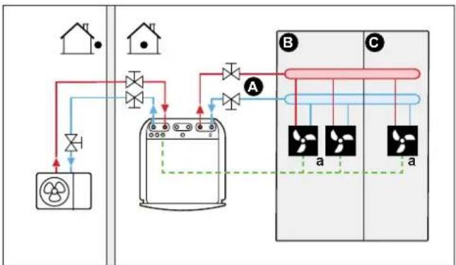
Setup
flowchart
graph TD
    A["HVAC Input"] --> B["Reactor"]
    B --> C["Air Fan"]
    C --> D["Component A"]
    D --> E["Output"]
    style A fill:#f9f,stroke:#333
    style B fill:#ccf,stroke:#333
    style C fill:#cfc,stroke:#333
    style D fill:#fcc,stroke:#333
    style E fill:#ffc,stroke:#333
A Main leaving water temperature zone
B Room 1
C Room 2
a Heat pump convectors (+ controllers)
- For more information about connecting the electrical wiring to the unit, see:
- "8.2 Connections to the outdoor unit" [▶ 92]
- "8.3 Connections to the indoor unit" [▶ 99]
- The desired room temperature is set via the controller of the heat pump convectors. There are different controllers and setups possible for the heat pump convectors. For more information, see:
- The installation manual of the heat pump convectors
- The installation manual of the heat pump convector options
- The addendum book for optional equipment
- The user interface integrated in the indoor unit decides the space operation mode.
- The heating or cooling demand signals of each heat pump convector are connected in parallel to the digital input on the indoor unit (X2M/35 and X2M/30). The indoor unit will only supply leaving water temperature when there is an actual demand.

INFORMATION
To increase comfort and performance, we recommend to install the valve kit option EKVKHPC on each heat pump convector.
Configuration
| Setting Value | |
| Unit temperature control:• #: [2.9]• Code: [C-07] | 1 (External room thermostat): Unit operation is decided by the external thermostat. |
| Number of water temperature zones:• #: [4.4]• Code: [7-02] | 0 (Single zone): Main |
Benefits
Compared with heat pump convectors for one room:
- Comfort. You can set the desired room temperature, including schedules, for each room via the remote controller of the heat pump convectors.
Combination: Underfloor heating + Heat pump convectors – Multiple rooms
Setup
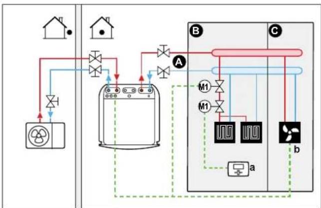
A Main leaving water temperature zone
B Room 1
C Room 2
a External room thermostat
b Heat pump convectors (+ controllers)
- For more information about connecting the electrical wiring to the unit, see:
- "8.2 Connections to the outdoor unit" [▶ 92]
- "8.3 Connections to the indoor unit" [▶ 99]
- For each room with heat pump convectors: The heat pump convectors are directly connected to the indoor unit.
- For each room with underfloor heating: Two shut-off valves (field supply) are installed before the underfloor heating:
- A shut-off valve to prevent hot water supply when the room has no heating demand
- A shut-off valve to prevent condensation on the floor during cooling operation of the rooms with heat pump convectors.
- For each room with heat pump convectors: The desired room temperature is set via the controller of the heat pump convectors. There are different controllers and setups possible for the heat pump convectors. For more information, see:
- The installation manual of the heat pump convectors
- The installation manual of the heat pump convector options
- The addendum book for optional equipment
- For each room with underfloor heating: The desired room temperature is set via the external room thermostat (wired or wireless).
- The user interface integrated in the indoor unit decides the space operation mode. Mind that the operation mode on each external room thermostat and controller of the heat pump convectors must be set to match the indoor unit.

INFORMATION
To increase comfort and performance, we recommend to install the valve kit option EKVKHPC on each heat pump convector.
Configuration
| Setting Value | |
| Unit temperature control:#: [2.9]Code: [C-07] | 0 (Leaving water): Unit operation is decided based on the leaving water temperature. |
| Number of water temperature zones:#: [4.4]Code: [7-02] | 0 (Single zone): Main |
5.2.3 Multiple rooms – Two LWT zones
In this document:
- Main zone = Zone with the lowest design temperature in heating, and the highest design temperature in cooling
- Additional zone = Zone with the highest design temperature in heating, and the lowest design temperature in cooling

CAUTION
If there is more than one leaving water zone, ALWAYS install a mixing valve station in the main zone to decrease (in heating)/increase (in cooling) the leaving water temperature when the additional zone has demand.
Typical example:
| Room (zone) Heat emitters: Design temperature | |
| Living room (main zone) Underfloor heating:In heating: 35°CIn cooling: 20°C (only refreshment, no real cooling allowed) | |
| Bed rooms (additional zone) Heat pump convectors:In heating: 45°CIn cooling: 12°C |
Setup
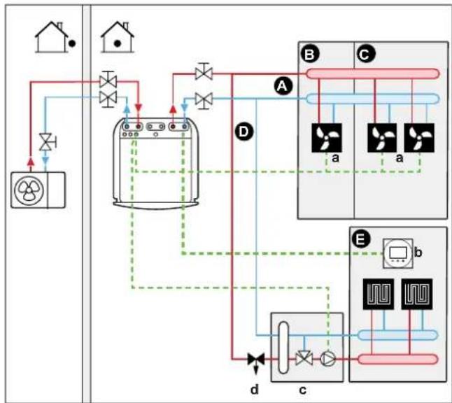
flowchart
graph TD
    A["House Unit"] --> B["HVAC"]
    B --> C["Reactor Unit"]
    C --> D["A"]
    C --> E["B"]
    C --> F["C"]
    C --> G["E"]
    G --> H["Control Panel"]
    H --> I["Output"]
    style A fill:#f9f,stroke:#333
    style B fill:#ccf,stroke:#333
    style C fill:#cfc,stroke:#333
    style D fill:#fcc,stroke:#333
    style E fill:#cff,stroke:#333
    style F fill:#ffc,stroke:#333
    style G fill:#cfc,stroke:#333
    style H fill:#fcc,stroke:#333
    style I fill:#ffc,stroke:#333
A Additional leaving water temperature zone
B Room 1
C Room 2
D Main leaving water temperature zone
E Room 3
a Heat pump convectors (+ controllers)
b Dedicated Human Comfort Interface (BRC1HHDA used as room thermostat)
c Mixing valve station
d Pressure regulating valve

INFORMATION
A pressure regulating valve should be implemented before the mixing valve station. This is to guarantee the correct water flow balance between the main leaving water temperature zone and the additional leaving water temperature zone in relation to the required capacity of both water temperature zones.
- For more information about connecting the electrical wiring to the unit, see:
- "8.2 Connections to the outdoor unit" [▶ 92]
- "8.3 Connections to the indoor unit" [▶ 99]
- For the main zone:
- A mixing valve station is installed before the underfloor heating.
- The pump of the mixing valve station is controlled by the ON/OFF signal on the indoor unit (X2M/29 and X2M/21; normally closed shut-off valve output).
- The room temperature is controlled by the dedicated Human Comfort Interface (BRC1HHDA used as room thermostat).
- For the additional zone:
- The heat pump convectors are directly connected to the indoor unit.
- The desired room temperature is set via the controller of the heat pump convectors. There are different controllers and setups possible for the heat pump convectors. For more information, see:
The installation manual of the heat pump convectors
The installation manual of the heat pump convector options
The addendum book for optional equipment
- The heating or cooling demand signals of each heat pump convector are connected in parallel to the digital input on the indoor unit (X2M/35a and X2M/30). The indoor unit will only supply the desired additional leaving water temperature when there is an actual demand.
- The user interface integrated in the indoor unit decides the space operation mode. Mind that the operation mode on each controller of the heat pump convectors must be set to match the indoor unit.
Configuration
| Setting Value | |
| Unit temperature control:• #: [2.9]• Code: [C-07] | 2 (Room thermostat): Unit operation is decided based on the ambient temperature of the dedicated Human Comfort Interface.Note:• Main room = dedicated Human Comfort Interface used as room thermostat functionality• Other rooms = external room thermostat functionality |
| Number of water temperature zones:• #: [4.4]• Code: [7-02] | 1 (Dual zone): Main + additional |
| In case of heat pump convectors:External room thermostat for theadditionalzone:• #: [3.A]• Code: [C-06] | 1 (1 contact): When the used external room thermostat or heat pump convector can only send a thermo ON/OFF condition. No separation between heating or cooling demand. |
| Shut-off valve output Set to follow the thermo demand of the main zone. | |
| Shut-off valve If the main zone must be shut off during cooling mode to prevent condensation on the floor, set it accordingly. | |
| At the mixing valve station Set the desired | main leaving water temperature for heating and/or cooling. |
Benefits
Comfort.
- The smart room thermostat functionality can decrease or increase the desired leaving water temperature based on the actual room temperature (modulation).
- The combination of the two heat emitter systems provides the excellent heating comfort of the underfloor heating, and the excellent cooling comfort of the heat pump convectors.
Efficiency.
- Depending on the demand, the indoor unit supplies different leaving water temperature matching the design temperature of the different heat emitters.
- Underfloor heating has the best performance with the heat pump system.
5.3 Setting up an auxiliary heat source for space heating
■ Space heating can be done by:
- The indoor unit
- An auxiliary boiler (field supply) connected to the system
- When the room thermostat requests heating, the indoor unit or the auxiliary boiler starts operating depending on the outdoor temperature (status of the changeover to external heat source). When the permission is given to the auxiliary boiler, the space heating by the indoor unit is turned OFF.
- Bivalent operation is only possible for space heating, NOT for domestic hot water production. Domestic hot water is always produced by the DHW tank connected to the indoor unit.

INFORMATION
- During heating operation of the heat pump, the heat pump operates to achieve the desired temperature set via the user interface. When weather-dependent operation is active, the water temperature is determined automatically depending on the outdoor temperature.
During heating operation of the auxiliary boiler, the auxiliary boiler operates to achieve the desired water temperature set via the auxiliary boiler controller.
Setup
- Integrate the auxiliary boiler as follows:
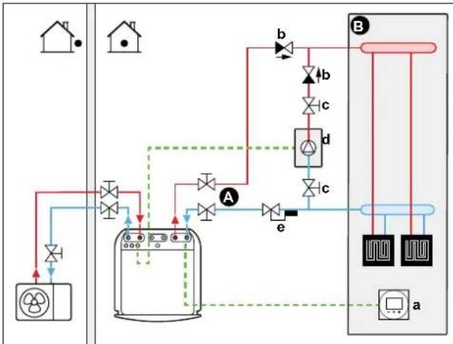
A Main leaving water temperature zone
B One single room
a Dedicated Human Comfort Interface (BRC1HHDA used as room thermostat)
b Non-return valve (field supply)
c Shut-off valve (field supply)
d Auxiliary boiler (field supply)
e Aquastat valve (field supply)

NOTICE
- Make sure the auxiliary boiler and its integration in the system complies with applicable legislation.
-
Daikin is NOT responsible for incorrect or unsafe situations in the auxiliary boiler system.
-
Make sure the return water to the heat pump does NOT exceed 60°C. To do so:
- Set the desired water temperature via the auxiliary boiler controller to maximum 60°C.
- Install an aquastat valve in the return water flow of the heat pump. Set the aquastat valve to close above 60°C and to open below 60°C.
- Install non-return valves.
- Make sure to only have one expansion vessel in the water circuit. An expansion vessel is already pre-mounted in the indoor unit.
- Install the digital I/O PCB (option EKRP1HBAA).
- Connect X1 and X2 (changeover to external heat source) on the digital I/O PCB to the auxiliary boiler. See "8.3.8 To connect the changeover to external heat source" [▶ 111].
- To setup the heat emitters, see "5.2 Setting up the space heating/cooling system" [▶ 28].
Configuration
Via the user interface (configuration wizard):
- Set the use of a bivalent system as external heat source.
- Set the bivalent temperature and hysteresis.
Changeover to external heat source decided by an auxiliary contact
- Only possible in external room thermostat control AND one leaving water temperature zone (see "5.2 Setting up the space heating/cooling system" [▶ 28]).
■ The auxiliary contact can be:
- An outdoor temperature thermostat
- An electricity tariff contact
- A manually operated contact
-
- Setup: Connect the following field wiring:
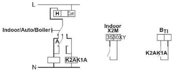
B_ Boiler thermostat input
A Auxiliary contact (normally closed)
H Heating demand room thermostat (optional)
K1A Auxiliary relay for activation of indoor unit (field supply)
K2A Auxiliary relay for activation of boiler (field supply)
Indoor Indoor unit
Auto Automatic
Boiler Boiler

NOTICE
■ Make sure the auxiliary contact has enough differential or time delay to prevent frequent changeover between indoor unit and auxiliary boiler.
- If the auxiliary contact is an outdoor temperature thermostat, install the thermostat in the shadow so that it is NOT influenced or turned ON/OFF by direct sunlight.
- Frequent changeover may cause corrosion of the auxiliary boiler. Contact the manufacturer of the auxiliary boiler for more information.
Setpoint of the auxiliary gas boiler
To prevent freeze-up of the water piping, the auxiliary gas boiler must have a fixed setpoint ≥ 55^ , or a weather-dependent setpoint ≥ T_min .
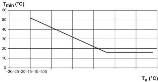
line
| Ta (°C) | Tmin (°C) | | ------- | --------- | | -30 | 52 | | 0 | 40 | | 25 | 20 | | 50 | 15 | | 75 | 15 |T_a Outdoor temperature
T_min Minimum weather-dependent setpoint for auxiliary gas boiler
5.4 Setting up the domestic hot water tank
5.4.1 System layout – Integrated DHW tank
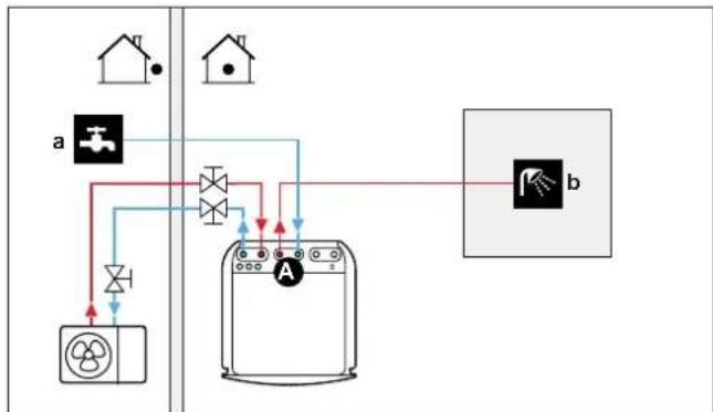
A Domestic hot water
a Cold water IN
b Hot water OUT
5.4.2 Selecting the volume and desired temperature for the DHW tank
People experience water as hot when its temperature is 40^ C. Therefore, the DHW consumption is always expressed as equivalent hot water volume at 40^ C. However, you can set the DHW tank temperature at a higher temperature (example: 53^ C), which is then mixed with cold water (example: 15^ C).
Selecting the volume and desired temperature for the DHW tank consists of:
1 Determining the DHW consumption (equivalent hot water volume at 40°C).
2 Determining the volume and desired temperature for the DHW tank.
Determining the DHW consumption
Answer the following questions and calculate the DHW consumption (equivalent hot water volume at 40^ C) using typical water volumes:
| Question Typical water volume | |
| How many showers are needed per day? | 1 shower = 10 min×10 l/min = 100 l |
| How many baths are needed per day? 1 bath = 150 l | |
| How much water is needed at the kitchen sink per day? | 1 sink = 2 min×5 l/min = 10 l |
| Are there any other domestic hot water needs? | — |
Example: If the DHW consumption of a family (4 persons) per day is as follows:
3 showers
1 bath
- 3 sink volumes
Then the DHW consumption = (3×100 l)+(1×150 l)+(3×10 l)=480 l
Determining the volume and desired temperature for the DHW tank
| Formula Example | |
| V_1 = V_2 + V_2 × (T_2 - 40) / (40 - T_1) If: | V_2 = 180 T_2 = 54°C T_1 = 15°C Then V_1 = 280 I |
| V_2 = V_1 × (40 - T_1) / (T_2 - T_1) If: | V_1 = 480 T_2 = 54°C T_1 = 15°C Then V_2 = 307 I |
V_1 DHW consumption (equivalent hot water volume at 40^ C)
V_2 Required DHW tank volume if only heated once
T_2 DHW tank temperature
T_1 Cold water temperature
- If the DHW consumption differs from day to day, you can program a weekly schedule with different desired DHW tank temperatures for each day.
- The lower the desired DHW tank temperature, the more cost effective. By selecting a larger DHW tank, you can lower the desired DHW tank temperature.
- The heat pump itself can produce domestic hot water of maximum 55°C (50°C if outdoor temperature is low). The electrical resistance integrated in the heat pump can increase this temperature. However, this consumes more energy. We recommend to set the desired DHW tank temperature below 55°C to avoid using the electrical resistance.
- The higher the outdoor temperature, the better the performance of the heat pump.
- If energy prices are the same during the day and the night, we recommend to heat up the DHW tank during the day.
- If energy prices are lower during the night, we recommend to heat up the DHW tank during the night.
- When the heat pump produces domestic hot water, it cannot heat up a space. In case you need domestic hot water and space heating at the same, we recommend to produce the domestic hot water during the night when there is lower space heating demand.
5.4.3 Setup and configuration – DHW tank
- For large DHW consumptions, you can heat up the DHW tank several times during the day.
- To heat up the DHW tank to the desired DHW tank temperature, you can use the following energy sources:
- Thermodynamic cycle of the heat pump
- Electrical backup heater
- For more information about optimizing the energy consumption for producing domestic hot water, see "9 Configuration" [▶ 116].
5.4.4 DHW pump for instant hot water
Setup
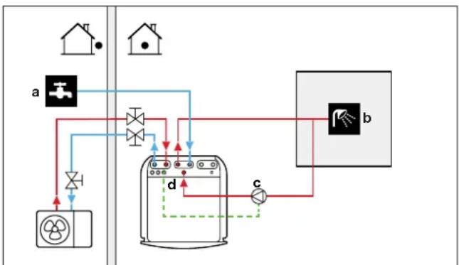
flowchart
graph TD
    A["House Unit"] --> B["Refrigerator"]
    B --> C["Refrigerator unit"]
    C --> D["Control Valve"]
    D --> E["Refrigerator unit"]
    E --> F["Refrigerator unit"]
    F --> G["Refrigerator unit"]
    G --> H["Refrigerator unit"]
    H --> I["Refrigerator unit"]
    I --> J["Refrigerator unit"]
    J --> K["Refrigerator unit"]
    K --> L["Refrigerator unit"]
    L --> M["Refrigerator unit"]
    M --> N["Refrigerator unit"]
    N --> O["Refrigerator unit"]
    O --> P["Refrigerator unit"]
    P --> Q["Refrigerator unit"]
    Q --> R["Refrigerator unit"]
    R --> S["Refrigerator unit"]
    S --> T["Refrigerator unit"]
    T --> U["Refrigerator unit"]
    U --> V["Refrigerator unit"]
    V --> W["Refrigerator unit"]
    W --> X["Refrigerator unit"]
    X --> Y["Refrigerator unit"]
    Y --> Z["Refrigerator unit"]
a Cold water IN
b Hot water OUT (shower (field supply))
c DHW pump (field supply)
d Recirculation connection
- By connecting a DHW pump, instant hot water can be available at the tap.
- The DHW pump and the installation are field supply and the responsibility of the installer. For the electrical wiring, see "8.3.5 To connect the domestic hot water pump" [▶ 108].
For more information about connecting the recirculation connection, see "7.2.4 To connect the recirculation piping" [▶ 82].
Configuration
- For more information, see "9 Configuration" [▶ 116].
- You can program a schedule to control the DHW pump via the user interface. For more information, see the user reference guide.
a Cold water IN
b Hot water OUT (shower (field supply))
c DHW pump (field supply)
d Heater element (field supply)
e Non-return valve (field supply)
- The DHW pump is field-supplied and its installation is the responsibility of the installer. For the electrical wiring, see "8.3.5 To connect the domestic hot water pump" [▶ 108].
- If the applicable legislation requires a higher temperature than the maximum tank setpoint during disinfection (see [2-03] in the field settings table), you can connect a DHW pump and heater element as shown above.
- If applicable legislation requires disinfection of the water piping until the tapping point, you can connect a DHW pump and heater element (if needed) as shown above.
Configuration
The indoor unit can control DHW pump operation. For more information, see "9 Configuration" [▶ 116].
5.5 Setting up the energy metering
- Via the user interface, you can read out the following energy data:
- Produced heat
- Consumed energy
- You can read out the energy data:
- For space heating
- For space cooling
- For domestic hot water production
- You can read out the energy data:
- Per month
- Per year

INFORMATION
The calculated produced heat and consumed energy are an estimation, the accuracy cannot be guaranteed.
5.5.1 Produced heat

INFORMATION
The sensors used to calculate the produced heat are calibrated automatically.

INFORMATION
If glycol is present in the system ([E-0D]=1]), then the produced heat will NOT be calculated, nor will it be displayed on the user interface.
- The produced heat is calculated internally based on:
- The leaving and entering water temperature
- The flow rate
- Setup and configuration: No additional equipment needed.
5.5.2 Consumed energy
You can use the following methods to determine the consumed energy:
- Calculating
- Measuring

INFORMATION
You cannot combine calculating the consumed energy (example: for backup heater) and measuring the consumed energy (example: for outdoor unit). If you do so, the energy data will be invalid.
Calculating the consumed energy
- The consumed energy is calculated internally based on:
- The actual power input of the outdoor unit
- The set capacity of the backup heater
- The voltage
- Setup and configuration: To get accurate energy data, measure the capacity (resistance measurement) and set the capacity via the user interface for the backup heater (step 1).
Measuring the consumed energy
- Preferred method because of higher accuracy.
- Requires external power meters.
- Setup and configuration: When using electrical power meters, set the number of pulses/kWh for each power meter via the user interface.

INFORMATION
When measuring the electrical power consumption, make sure ALL power input of the system is covered by the electrical power meters.
5.5.3 Normal kWh rate power supply
General rule
One power meter that covers the entire system is sufficient.
Setup
Connect the power meter to X5M/5 and X5M/6. See "8.3.4 To connect the electricity meters" [▶ 107].
Power meter type
| In case of... Use a... power meter | |
| Single-phase outdoor unitBackup heater supplied from a single-phase grid (i.e. the backup heater model is *3V or *6V connected to a single-phase grid) | Single-phase(*3V, *6V (6V): 1N~230 V) |
| Three-phase outdoor unitBackup heater supplied from a three-phase grid (i.e. the backup heater model is *9W or *6V connected to a three-phase grid) | Three-phase(*6V (6T1): 3~230 V)(*9W: 3N~400 V) |
Example
| Single-phase power meter Three-phase power meter | ||
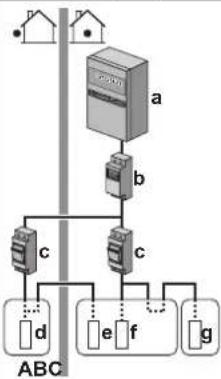 | 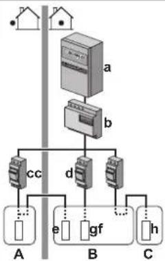 | |
| A Outdoor unitB Indoor unitC DHW tanka Electrical cabinet (L1/N)b Power meter (L1/N)c Fuse (L1/N)d Outdoor unit (L1/N)e Indoor unit (L1/N)f Backup heater (L1/N)g Booster heater (L1/N) | A Outdoor unitB Indoor unitC DHW tanka Electrical cabinet (L1/L2/L3/N)b Power meter (L1/L2/L3/N)c Fuse (L1/L2/L3/N)d Fuse (L1/N)e Outdoor unit (L1/L2/L3/N)f Indoor unit (L1/L2/L3/N)g Backup heater (L1/L2/L3/N)h Booster heater (L1/N) | |
Exception
- You can use a second power meter if:
- The power range of one meter is insufficient.
- The electrical meter cannot easily be installed in the electrical cabinet.
- 230 V and 400 V three-phase grids are combined (very uncommon), because of technical limitations of power meters.
■ Connection and setup:
- Connect the second power meter to X5M/3 and X5M/4. See "8.3.4 To connect the electricity meters" [▶ 107].
- In the software the power consumption data of both meters is added so you do NOT have to set which meter covers which power consumption. You only need to set the number of pulses of each power meter.
- See "5.5.4 Preferential kWh rate power supply" [▶ 49] for an example with two power meters.
5.5.4 Preferential kWh rate power supply
General rule
■ Power meter 1: Measures the outdoor unit.
- Power meter 2: Measures the rest (i.e. indoor unit and backup heater).
Setup
- Connect power meter 1 to X5M/5 and X5M/6.
- Connect power meter 2 to X5M/3 and X5M/4.
See "8.3.4 To connect the electricity meters" [▶ 107].
Power meter types
- Power meter 1: Single- or three-phase power meter according to the power supply of the outdoor unit.
Power meter 2:
- In case of a single-phase backup heater configuration, use a single-phase power meter.
- In other cases, use a three-phase power meter.
Example
Single-phase outdoor unit with a three-phase backup heater:
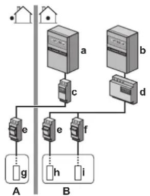
5.6 Setting up the power consumption control
You can use the following power consumption controls. For more information about the corresponding settings, see "Power consumption control" [▶ 184].
| # Power consumption control | |
| 1 | "5.6.1 Permanent power limitation" [▶ 50]Allows you to limit the power consumption of the entire heat pump system (sum of indoor unit and backup heater) with one permanent setting.Limitation of power in kW or current in A. |
| 2 | "5.6.2 Power limitation activated by digital inputs" [▶ 51]Allows you to limit the power consumption of the entire heat pump system (sum of indoor unit and backup heater) via 4 digital inputs.Limitation of power in kW or current in A. |
| 3 | "5.6.4 BBR16 power limitation" [▶ 53]Restriction: Only available in Swedish language.Allows you to comply with BBR16 regulations (Swedish energy regulations).Limitation of power in kW.Can be combined with the other power consumption controls. If you do so, the unit uses the most restrictive control. |

NOTICE
It is possible to install a field fuse with lower than recommended rating over the heat pump. For this you must modify field setting [2-0E] according to the maximum allowed current over the heat pump.
Note that field setting [2-0E] overrules all power consumption control settings. Power limiting the heat pump will reduce performance.
5.6.1 Permanent power limitation
Permanent power limitation is useful to assure a maximum power or current input of the system. In some countries, legislation limits the maximum power consumption for space heating and DHW production.
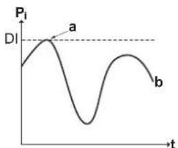
line
| t | P1 | | ---- | ------ | | 0 | 0 | | Peak | a | | Low | b | | High | b |P_i Power input
t Time
DI Digital input (power limitation level)
a Power limitation active
b Actual power input
Setup and configuration
- No additional equipment needed.
-
Set the power consumption control settings in [9.9] via the user interface (see "Power consumption control" [▶ 184]):
-
Select continuous limitation mode
- Select the type of limitation (power in kW or current in A)
- Set the desired power limitation level

NOTICE
Set a minimum power consumption of ±3.6 kW to guarantee:
- Defrost operation. Otherwise, if defrosting is interrupted several times, the heat exchanger will freeze up.
■ Space heating and DHW production by allowing the backup heater step 1.
5.6.2 Power limitation activated by digital inputs
Power limitation is also useful in combination with an energy management system. The power or current of the entire Daikin system is limited dynamically by digital inputs (maximum four steps). Each power limitation level is set via the user interface by limiting one of the following:
- Current (in A)
■ Power input (in kW)
The energy management system (field supply) decides the activation of a certain power limitation level. Example: To limit the maximum power of the entire house (lighting, domestic appliances, space heating...).
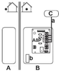
A Outdoor unit
B Indoor unit
C Energy management system
a Power limitation activation (4 digital inputs
b Backup heater
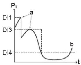
line
| t | P_i | | ---- | ---- | | DI1 | PI | | DI3 | PI | | DI4 | PI |P_i Power input
t Time
DI Digital inputs (power limitation levels)
a Power limitation active
b Actual power input
Setup
- Demand PCB (option EKRP1AHTA) needed.
- Maximum four digital inputs are used to activate the corresponding power limitation level:
- DI1 = strongest limitation (lowest energy consumption)
- DI4 = weakest limitation (highest energy consumption)
- Specification of the digital inputs:
DI 1 S9S limit 1
DI 2 S8S limit 2
DI 3 S7S limit 3
DI 4 S6S limit 4
- Refer to the wiring diagram for more information.
Configuration
- Set the power consumption control settings in [9.9] via the user interface (for the description of all settings, see "Power consumption control" [▶ 184]):
- Select limitation by digital inputs.
- Select the type of limitation (power in kW or current in A).
- Set the desired power limitation level corresponding to each digital input.

INFORMATION
In case more than 1 digital input is closed (at the same time), the digital input priority is fixed: DI4 priority>...>DI1.
5.6.3 Power limitation process
The outdoor unit has better efficiency than the electrical heater. Therefore, the electrical heater is limited and turned OFF first. The system limits power consumption in the following order:
1 Turns OFF the backup heater.
2 Limits the outdoor unit.
3 Turns OFF the outdoor unit.
Example
If the configuration is as follows: Power limitation level does NOT allow operation of backup heater (step 1).
Then power consumption is limited as follows:
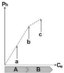
P_h Produced heat
C. Consumed energy Consumed energy
A Outdoor unit
B Backup heater
a Limited outdoor unit operation
5.6.4 BBR16 power limitation

INFORMATION
Restriction: BBR16 settings are only visible when the language of the user interface is set to Swedish.

NOTICE
2 weeks to change. After you activated BBR16, you only have 2 weeks to change its settings (BBR16 activation and BBR16 power limit). After 2 weeks, the unit freezes these settings.
Note: This is different from the permanent power limitation, which is always changeable.
Use the BBR16 power limitation when you must comply with BBR16 regulations (Swedish energy regulations).
You can combine the BBR16 power limitation with the other power consumption controls. If you do so, the unit uses the most restrictive control.
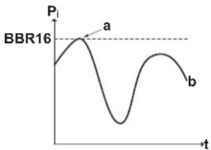
line
| t | P₁ | | ---- | ------ | | 0 | Peak | | Peak | a | | Peak | b |P Power input
t Time
BBR16 BBR16 limit level
a Power limitation active
b Actual power input
Setup and configuration
- No additional equipment needed.
- Set the power consumption control settings in [9.9] via the user interface (see "Power consumption control" [▶ 184]):
- Activate BBR16
- Set the desired power limitation level
5.7 Setting up an external temperature sensor
You can connect one external temperature sensor. It measures the indoor or outdoor ambient temperature. We recommend to use an external temperature sensor in the following cases:
Indoor ambient temperature
- In room thermostat control, the dedicated Human Comfort Interface (BRC1HHDA used as room thermostat) measures the indoor ambient temperature. Therefore, the Human Comfort Interface must be installed on a location:
- Where the average temperature in the room can be detected
- That is NOT exposed to direct sunlight
- That is NOT near a heat source
- That is NOT affected by outside air or air draught because of, for example, door opening/closing
- If this is NOT possible, we recommend to connect a remote indoor sensor (option KRCS01-1).
- Setup: For installation instructions, see the installation manual of the remote indoor sensor, and the addendum book for optional equipment.
- Configuration: Select room sensor [9.B].
Outdoor ambient temperature
- In the outdoor unit, the outdoor ambient temperature is measured. Therefore, the outdoor unit must be installed on a location:
- At the north side of the house or at the side of the house where the most heat emitters are located
- That is NOT exposed to direct sunlight
- If this is NOT possible, we recommend to connect a remote outdoor sensor (option EKRSCA1).
- Setup: For installation instructions, see the installation manual of the remote outdoor sensor, and the addendum book for optional equipment.
- Configuration: Select outdoor sensor [9.B].
- When the power saving functionality of the outdoor unit is active (see "Power saving function" [▶ 192]), the outdoor unit is turned down to reduce standby energy losses. As a result, the outdoor ambient temperature is NOT read out.
- If the desired leaving water temperature is weather dependent, the full time outdoor temperature measurement is important. This is another reason to install the optional outdoor ambient temperature sensor.

INFORMATION
The external outdoor ambient sensor data (either averaged or instantaneous) is used in the weather-dependent control curves and in the automatic heating/cooling changeover logic. To protect the outdoor unit, the internal sensor of the outdoor unit is always used.
6 Unit installation
In this chapter
6.1 Preparing the installation site 55
6.1.1 Installation site requirements of the outdoor unit 55
6.1.2 Additional installation site requirements of the outdoor unit in cold climates 58
6.1.3 Installation site requirements of the indoor unit 58
6.2 Opening and closing the units 59
6.2.1 About opening the units 59
6.2.2 To open the outdoor unit 59
6.2.3 To remove the transportation stay 60
6.2.4 To close the outdoor unit.... 60
6.2.5 To open the indoor unit 51
6.2.6 To lower the switch box on the indoor unit 63
6.2.7 To close the indoor unit 64
6.3 Mounting the outdoor unit 64
6.3.1 About mounting the outdoor unit 64
6.3.2 Precautions when mounting the outdoor unit.... 64
6.3.3 To provide the installation structure 64
6.3.4 To install the outdoor unit 65
6.3.5 To provide drainage 66
6.3.6 To install the discharge grille 68
6.3.7 To remove the discharge grille, and put the grille in safety position 59
6.4 Mounting the indoor unit 71
6.4.1 About mounting the indoor unit 71
6.4.2 Precautions when mounting the indoor unit 71
6.4.3 To install the indoor unit.... 71
6.4.4 To connect the drain hose to the drain 72
6.1 Preparing the installation site
Do NOT install the unit in places often used as work place. In case of construction works (e.g. grinding works) where a lot of dust is created, the unit MUST be covered.
Choose an installation location with sufficient space for carrying the unit in and out of the site.

WARNING
The appliance shall be stored in a room without continuously operating ignition sources (example: open flames, an operating gas appliance or an operating electric heater).
6.1.1 Installation site requirements of the outdoor unit

INFORMATION
Also read the precautions and requirements in the "General safety precautions" chapter.
Mind the spacing guidelines. See "15.1 Service space: Outdoor unit" [▶ 232].

NOTICE
- Do NOT stack the units on each other.
- Do NOT hang the unit on a ceiling.
Strong winds ( ≥ 18 km/h) blowing against the outdoor unit's air outlet causes short circuit (suction of discharge air). This may result in:
- deterioration of the operational capacity;
- frequent frost acceleration in heating operation;
- disruption of operation due to decrease of low pressure or increase of high pressure;
- a broken fan (if a strong wind blows continuously on the fan, it may start rotating very fast, until it breaks).
It is recommended to install a baffle plate when the air outlet is exposed to wind. It is recommended to install the outdoor unit with the air inlet facing the wall and NOT directly exposed to the wind.
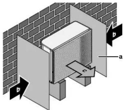
a Baffle plate b Prevailing wind direction c Air outlet
Do NOT install the unit in the following places:
- Sound sensitive areas (e.g. near a bedroom), so that the operation noise will cause no trouble.
Note: If the sound is measured under actual installation conditions, the measured value might be higher than the sound pressure level mentioned in Sound spectrum in the data book due to environmental noise and sound reflections.
- In places where a mineral oil mist, spray or vapour may be present in the atmosphere. Plastic parts may deteriorate and fall off or cause water leakage.
It is NOT recommended to install the unit in the following places because it may shorten the life of the unit:
■ Where the voltage fluctuates a lot
In vehicles or vessels
■ Where acidic or alkaline vapour is present
Seaside installation. Make sure the outdoor unit is NOT directly exposed to sea winds. This is to prevent corrosion caused by high levels of salt in the air, which might shorten the life of the unit.
Install the outdoor unit away from direct sea winds.
Example: Behind the building.
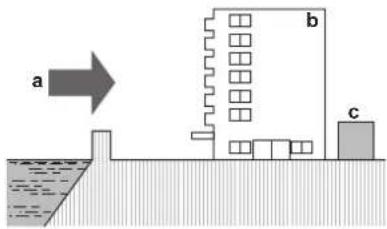
If the outdoor unit is exposed to direct sea winds, install a windbreaker.
- Height of windbreaker≥1.5×height of outdoor unit
- Mind the service space requirements when installing the windbreaker.
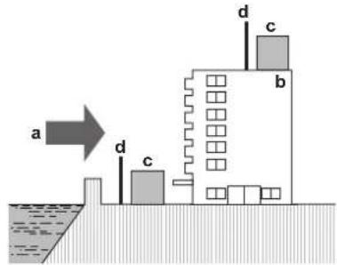
a Sea wind
b Building
c Outdoor unit
d Windbreaker
The outdoor unit is designed for outdoor installation only, and for the following ambient temperatures:
| Cooling mode 10~43°C | |
| Heating mode -28~35°C |
Special requirements for R32
The outdoor unit contains an internal refrigerant circuit (R32), but you do NOT have to do any refrigerant field piping, or refrigerant charging.
Mind the following requirements and precautions:

WARNING
- Do NOT pierce or burn.
- Do NOT use means to accelerate the defrosting process or to clean the equipment, other than those recommended by the manufacturer.
- Be aware that R32 refrigerant does NOT contain an odour.

WARNING
The appliance shall be stored so as to prevent mechanical damage and in a well-ventilated room without continuously operating ignition sources (example: open flames, an operating gas appliance or an operating electric heater).

WARNING
Make sure installation, servicing, maintenance and repair comply with instructions from Daikin and with applicable legislation (for example national gas regulation) and are executed only by authorised persons.
6.1.2 Additional installation site requirements of the outdoor unit in cold climates
Protect the outdoor unit against direct snowfall and take care that the outdoor unit is NEVER snowed up.
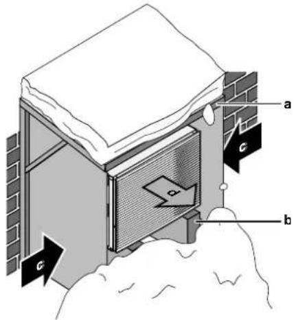
a Snow cover or shed
b Pedestal
c Prevailing wind direction
d Air outlet
In any case, provide at least 150 mm of free space below the unit. Additionally, make sure the unit is positioned at least 100 mm above the maximum expected level of snow. See "6.3 Mounting the outdoor unit" [▶ 64] for more details.
In heavy snowfall areas it is very important to select an installation site where the snow will NOT affect the unit. If lateral snowfall is possible, make sure that the heat exchanger coil is NOT affected by the snow. If necessary, install a snow cover or shed and a pedestal.
6.1.3 Installation site requirements of the indoor unit

INFORMATION
Also read the precautions and requirements in the "General safety precautions" chapter.
- The indoor unit is designed for indoor installation only and for the following ambient temperatures:
- Space heating operation: 5\~30°C
- Space cooling operation: 5\~35°C
- Domestic hot water production: 5\~35°C

INFORMATION
Cooling is only applicable in case of:
■ Reversible models
■ Heating only models + conversion kit (EKHVCONV2)
- Mind the measurement guidelines:
| Maximum height difference between indoor unit and outdoor unit | 10 m |
| Maximum total water piping length 50 m | (a) |
(i) Precise water piping length can be determined using the Hydronic Piping Calculation tool. The Hydronic Piping Calculation tool is part of the Heating Solutions Navigator which can be reached via https://professional.standbyme.daikin.eu. Please contact your dealer if you have no access to Heating Solutions Navigator.
- Mind the following spacing installation guidelines:
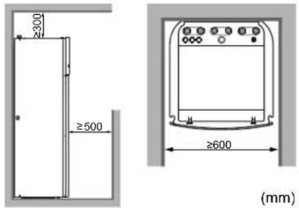

INFORMATION
If you have limited installation space, do the following before installing the unit in its final position: "6.4.4 To connect the drain hose to the drain" [▶ 72]. It requires to remove one or both side panels.
- The foundation must be strong enough to bear the weight of the unit. Take the weight of the unit with a domestic hot water tank full of water into account. Make sure, in the event of a water leak, water cannot cause any damage to the installation space and surroundings.
Do NOT install the unit in places such as:
- In places where a mineral oil mist, spray or vapour may be present in the atmosphere. Plastic parts may deteriorate and fall off or cause water leakage.
- Sound sensitive areas (e.g. near a bedroom), so that the operation noise will cause no trouble.
- In places with high humidity (max. RH=85%), for example a bathroom.
- In places where frost is possible. Ambient temperature around the indoor unit must be >5°C.
6.2 Opening and closing the units
6.2.1 About opening the units
At certain times, you have to open the unit. Example:
- When connecting the electrical wiring
- When maintaining or servicing the unit

DANGER: RISK OF ELECTROCUTION
Do NOT leave the unit unattended when the service cover is removed.
6.2.2 To open the outdoor unit

DANGER: RISK OF ELECTROCUTION

DANGER: RISK OF BURNING
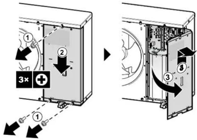
6.2.3 To remove the transportation stay

NOTICE
If the unit is operated with the transportation stay attached, abnormal vibration or noise may be generated.
The transportation stays (2×) protect the unit during transport. During installation they must be removed.
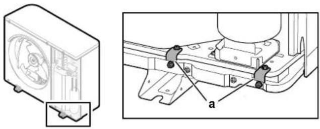
natural_image
Technical line drawing of a mechanical assembly with two views: top shows a fan component, bottom shows a bracket with mounting holes and labeled part 'a' (no text or symbols beyond labels)a Transportation stays (2×)
1 Open the switch box cover. See "6.2.2 To open the outdoor unit" [▶ 59].
2 Remove the screws (4×) from the transportation stays, and dispose of them.
3 Remove the transportation stays (2×), and dispose of them.
6.2.4 To close the outdoor unit

NOTICE
When closing the outdoor unit cover, make sure that the tightening torque does NOT exceed 4.1 N•m.
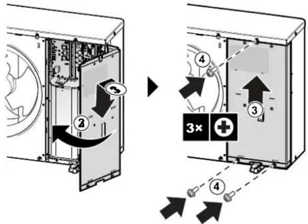
6.2.5 To open the indoor unit
Overview
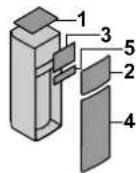
a Top panel
b User interface panel
c Switch box cover
d Front panel
e High voltage switch box cover
Open
1 Remove the top panel.
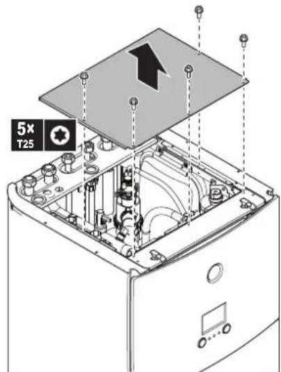
2 Remove the user interface panel. Open the hinges at the top and slide the top panel upwards.

NOTICE
If you remove the user interface panel, also disconnect the cables from the back of the user interface panel to prevent damage.
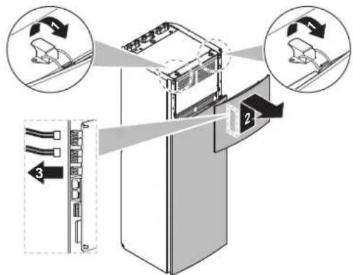
3 Remove the switch box cover.
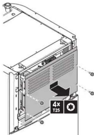
4 If necessary, remove the front plate. This is, for example, necessary in the following cases:
- "6.2.6 To lower the switch box on the indoor unit" [▶ 63]
- "6.4.4 To connect the drain hose to the drain" [▶ 72]
- When you need access to the high voltage switch box
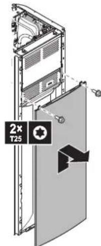
5 If you need access to the high voltage components, remove the high voltage switch box cover.
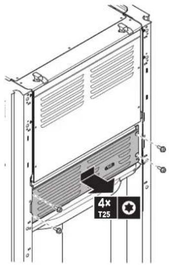
6.2.6 To lower the switch box on the indoor unit
During the installation, you will need access to the inside of the indoor unit. To have easier front access, put the switch box lower on the unit as follows:
Prerequisite: The user interface panel and front panel have been removed.
1 Remove the fixing plate at the top of the unit.
2 Tilt the switch box to the front and lift it out of its hinges.
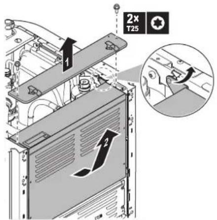
3 Place the switch box lower on the unit. Use the 2 hinges located lower on the unit.
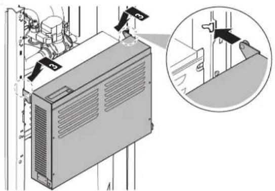
natural_image
Diagram of an air conditioner unit with attached sensors and a magnified inset showing the device's handle (no text or symbols present)6.2.7 To close the indoor unit
1 Close the cover of the switch box.
2 Put the switch box back into place.
3 Reinstall the top panel.
4 Reinstall the side panels.
5 Reinstall the front panel.
6 Reconnect the cables to the user interface panel.
7 Reinstall the user interface panel.

NOTICE
When closing the indoor unit cover, make sure that the tightening torque does NOT exceed 4.1 N•m.
6.3 Mounting the outdoor unit
6.3.1 About mounting the outdoor unit
When
You have to mount the outdoor unit before you can connect the water piping.
Typical workflow
Mounting the outdoor unit typically consists of the following stages:
1 Providing the installation structure.
2 Installing the outdoor unit.
3 Providing drainage.
4 Installing the discharge grille.
5 Protecting the unit against snow and wind by installing a snow cover and baffle plates. See "6.1 Preparing the installation site" [▶ 55].
6.3.2 Precautions when mounting the outdoor unit

INFORMATION
Also read the precautions and requirements in the following chapters:
■ "1 General safety precautions" [▶ 6]
■ "6.1 Preparing the installation site" [▶ 55]
6.3.3 To provide the installation structure
Check the strength and level of the installation ground so that the unit will not cause any operating vibration or noise.
Fix the unit securely by means of foundation bolts in accordance with the foundation drawing.
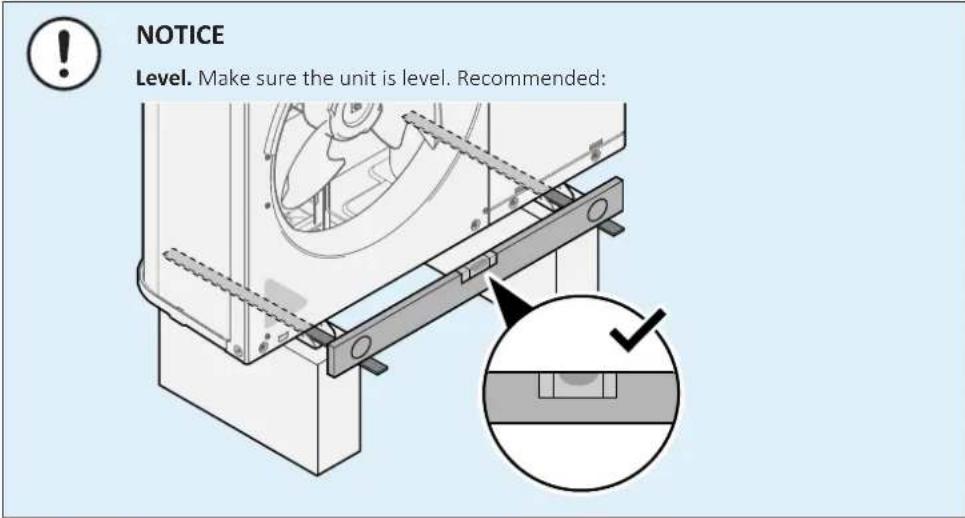
Use 4 sets of M12 anchor bolts, nuts and washers. Provide at least 150 mm of free space below the unit. Additionally, make sure the unit is positioned at least 100 mm above the maximum expected level of snow.
Anchor points
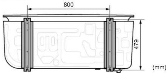
Pedestal
When installing on a pedestal, make sure that the discharge grille still can be put in its safety position. See "6.3.7 To remove the discharge grille, and put the grille in safety position" [▶ 69].
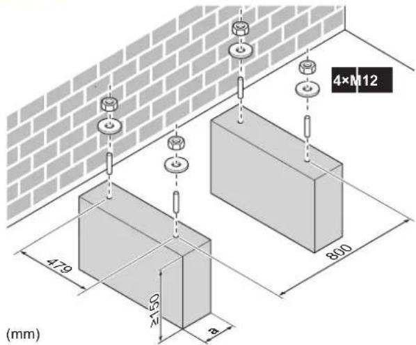
a Make sure not to cover the drain hole in the bottom plate of the unit.
6.3.4 To install the outdoor unit
1 Carry the unit by its slings, and put it onto the installation structure.
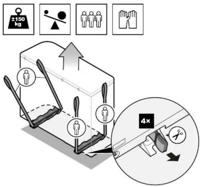
2 Fix the unit to the installation structure.
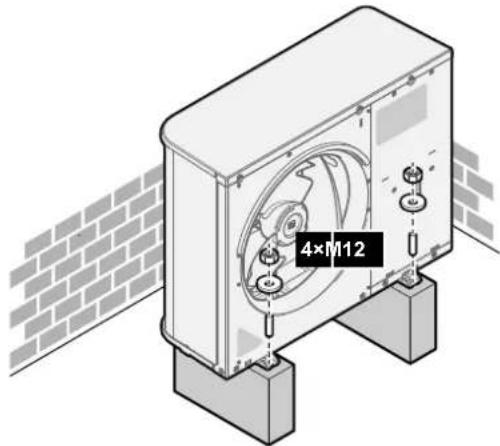
3 Remove the slings (and screws), and dispose of them.
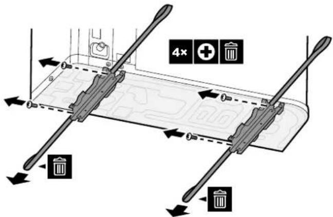
6.3.5 To provide drainage
- Make sure that condensation water can be evacuated properly.
- Install the unit on a base to make sure that there is proper drainage in order to avoid ice accumulation.
-
Prepare a water drainage channel around the foundation to drain waste water away from the unit.
-
Avoid drain water flowing over the footpath, so that it does NOT become slippery in case of ambient freezing temperatures.
- If you install the unit on a frame, install a waterproof plate within 150 mm of the bottom side of the unit in order to prevent water from getting into the unit and to avoid drain water dripping (see the following figure).
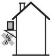

NOTICE
If the unit is installed in a cold climate, take adequate measures so that the evacuated condensate CANNOT freeze. We recommend to do the following:
Insulate the drain hose.
- Install a drain tube heater (field supply). To connect the drain tube heater, see "8.2.1 To connect the electrical wiring to the outdoor unit" [▶ 92].

NOTICE
Provide at least 150 mm of free space below the unit. Additionally, make sure the unit is positioned at least 100 mm above the expected level of snow.
Use the drain plug (with O-ring) and a hose for drainage.
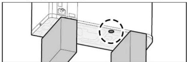
natural_image
Technical line drawing of a mechanical assembly with a dashed circular feature (no text or symbols)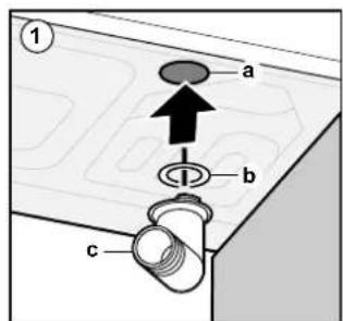
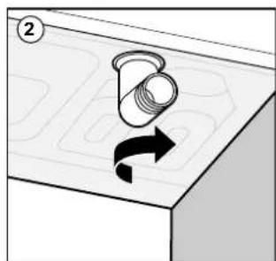
natural_image
Diagram showing a mechanical component with a rotating arrow, no text or symbols present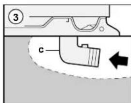
a Drain hole
b O-ring (delivered as accessory)
c Drain plug (delivered as accessory)
d Hose (field supply)

NOTICE
O-ring. Make sure the O-ring is installed correctly to prevent leakage.
6.3.6 To install the discharge grille

INFORMATION
Electrical wiring. Before installing the discharge grille, connect the electrical wiring.
Install the lower part of the discharge grille
1 Insert the hooks.
2 Insert the ball studs.
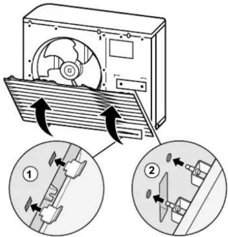
3 Fix the 2 lower screws.
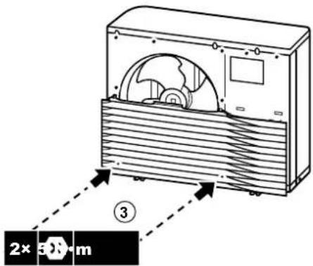
Install the upper part of the discharge grille

NOTICE
Vibrations. Make sure the upper part of the discharge grille is attached seamlessly to the lower part to prevent vibrations.
4 Align and attach the left side.
5 Align and attach the middle part.
6 Align and attach the right side.
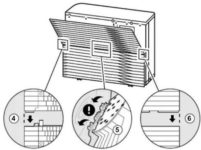
7 Insert the hooks.
8 Insert the ball studs.
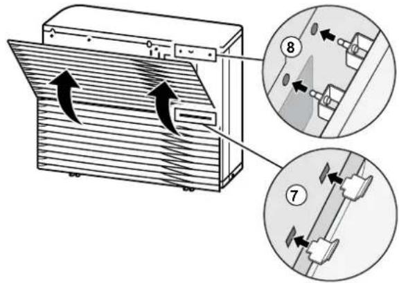
9 Fix the 6 remaining screws.
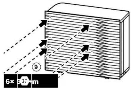
6.3.7 To remove the discharge grille, and put the grille in safety position

WARNING
Rotating fan. Before powering ON or servicing the outdoor unit, make sure that the discharge grille covers the fan as protection against a rotating fan. See:
- "6.3.6 To install the discharge grille" [▶ 68]
- "6.3.7 To remove the discharge grille, and put the grille in safety position" [▶ 69]
1 Remove the upper part of the discharge grille.
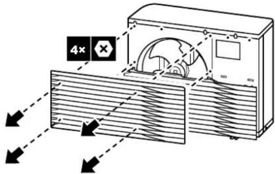
2 Remove the lower part of the discharge grille.
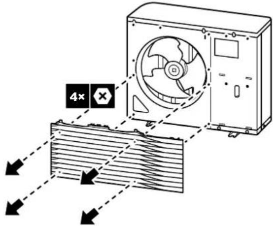
3 Rotate the lower part of the discharge grille.
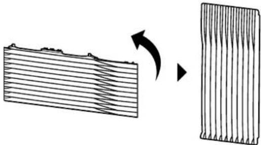
natural_image
Diagram showing a wooden plank transforming into a textured rectangular block with a curved arrow indicating rotation (no text or symbols)4 Align the ball stud and hook on the grille with their counterparts on the unit.
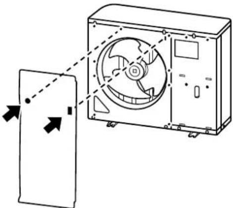
natural_image
Diagram of a device with a fan and control panel, showing alignment arrows (no text or symbols)5 Insert the hook.
6 Insert the ball stud.
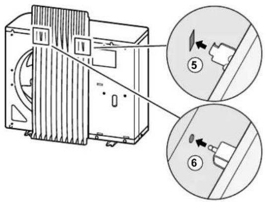
6.4 Mounting the indoor unit
6.4.1 About mounting the indoor unit
Typical workflow
Mounting the indoor unit typically consists of the following stages: 1 Installing the indoor unit.
6.4.2 Precautions when mounting the indoor unit

INFORMATION
Also read the precautions and requirements in the following chapters:
- "1 General safety precautions" [▶ 6]
- "6.1 Preparing the installation site" [▶ 55]
6.4.3 To install the indoor unit
1 Lift the indoor unit from the pallet and place it on the floor. Also see "3.3.3 To handle the indoor unit" [▶ 21].
2 Connect the drain hose to the drain. See "6.4.4 To connect the drain hose to the drain" [▶ 72].
3 Slide the indoor unit into position.
4 Adjust the height of the leveling feet to compensate for floor irregularities. The maximum allowed deviation is 1°.
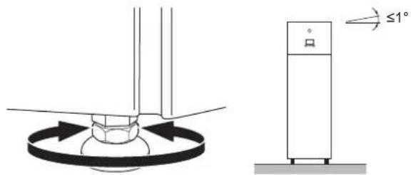
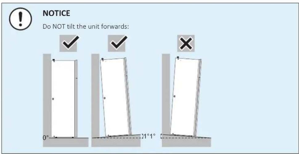
6.4.4 To connect the drain hose to the drain
Water coming from the pressure relief valve is collected in the drain pan. The drain pan is connected to a drain hose inside the unit. You must connect the drain hose to an appropriate drain according to the applicable legislation. You can route the drain hose through the left or right side panel.
Prerequisite: The user interface panel and front panel have been removed.
1 Remove one of the side panels.
2 Cut out the rubber grommet.
3 Pull the drain hose through the hole.
4 Reattach the side panel. Ensure the water can flow through the drain tube. It is recommended to use a tundish to collect the water.
Option 1: Through the left side panel
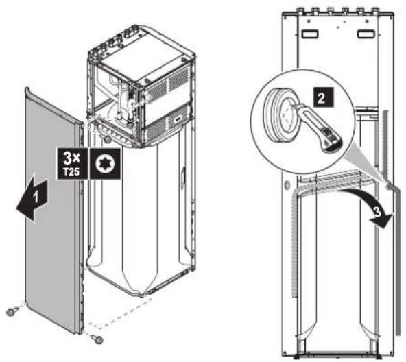
Option 2: Through the right side panel
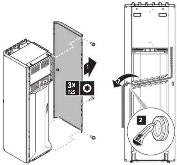
7 Piping installation
In this chapter
7.1 Preparing water piping 74
7.1.1 Water circuit requirements 74
7.1.2 Formula to calculate the expansion vessel pre-pressure.... 76
7.1.3 To check the water volume and flow rate 76
7.1.4 Changing the pre-pressure of the expansion vessel 79
7.1.5 To check the water volume: Examples 79
7.2 Connecting water piping 80
7.2.1 About connecting the water piping 80
7.2.2 Precautions when connecting the water piping.... 80
7.2.3 To connect the water piping.... 80
7.2.4 To connect the recirculation piping.... 82
7.2.5 To fill the water circuit 83
7.2.6 To protect the water circuit against freezing 83
7.2.7 To fill the domestic hot water tank 86
7.2.8 To insulate the water piping 86
7.1 Preparing water piping
7.1.1 Water circuit requirements

INFORMATION
Also read the precautions and requirements in the "General safety precautions" chapter.

NOTICE
In case of plastic pipes, make sure they are fully oxygen diffusion tight according to DIN 4726. The diffusion of oxygen into the piping can lead to excessive corrosion.
- Connecting piping – Legislation. Make all piping connections in accordance with the applicable legislation and the instructions in the "Installation" chapter, respecting the water inlet and outlet.
- Connecting piping – Force. Do NOT use excessive force when connecting the piping. Deformation of the piping can cause malfunctioning of the unit.
- Connecting piping – Tools. Only use appropriate tooling to handle brass, which is a soft material. If NOT, pipes will get damaged.
-
Connecting piping – Air, moisture, dust. If air, moisture or dust gets into the circuit, problems may occur. To prevent this:
-
Only use clean pipes
- Hold the pipe end downwards when removing burrs.
- Use a decent thread sealant to seal connections.
- Cover the pipe end when inserting it through a wall, to prevent dust and/or particles from entering the pipe.
- Insulation. Insulate up to the base of the heat exchanger.
- Freeze. Protect against freezing.
- Closed circuit. Use the indoor unit ONLY in a closed water system. Using the system in an open water system will lead to excessive corrosion.
- Piping length. It is recommended to avoid long runs of piping between the domestic hot water tank and the hot water end point (shower, bath,...) and to avoid dead ends.
- Piping diameter. Select the water piping diameter in relation to the required water flow and the available external static pressure of the pump. See "15 Technical data" [▶ 231] for the external static pressure curves of the indoor unit.
- Water flow. You can find the minimum required water flow for indoor unit operation in the following table. In all cases, this flow needs to be guaranteed. When the flow is lower, the indoor unit will stop operation and display error 7H.
Minimum required flow rate
25 l/min
- Field supply components – Water. Only use materials that are compatible with water used in the system and with the materials used in the indoor unit.
- Field supply components – Water pressure and temperature. Check that all components in the field piping can withstand the water pressure and water temperature.
- Water pressure. The maximum water pressure is 4 bar. Provide adequate safeguards in the water circuit to ensure that the maximum pressure is NOT exceeded.
- Water temperature. All installed piping and piping accessories (valve, connections,...) MUST withstand the following temperatures:

INFORMATION
The following illustration is an example and might NOT match your system layout.
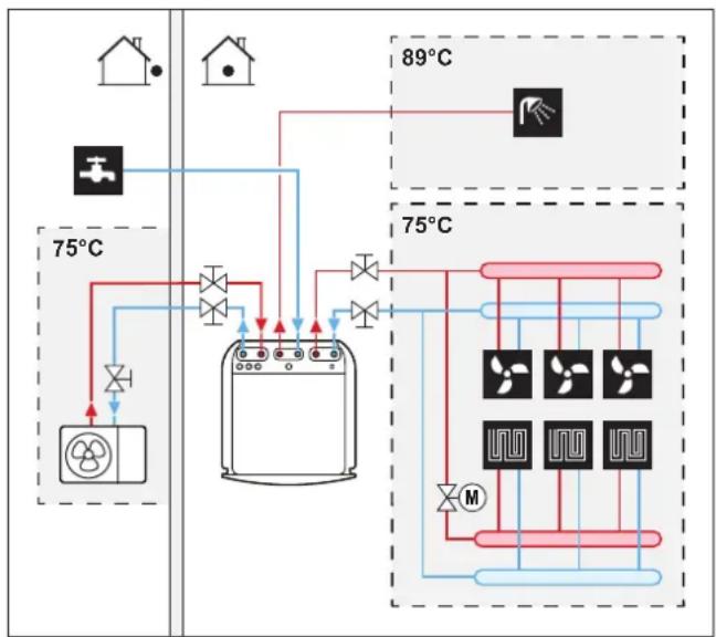
flowchart
graph TD
    A["House with Air Inlet"] --> B["75°C"]
    B --> C["Refrigerator"]
    C --> D["89°C Air Inverter"]
    D --> E["Fan Unit"]
    style A fill:#f9f,stroke:#333
    style B fill:#ccf,stroke:#333
    style C fill:#cfc,stroke:#333
    style D fill:#fcc,stroke:#333
    style E fill:#ffc,stroke:#333
- Drainage – Low points. Provide drain taps at all low points of the system in order to allow complete drainage of the water circuit.
- Drainage – Pressure relief valve. Connect the drain hose properly to the drain to avoid water dripping out of the unit. See "6.4.4 To connect the drain hose to the drain" [▶ 72].
- Air vents. Provide air vents at all high points of the system, which must also be easily accessible for servicing. Two automatic air purges are provided in the indoor unit. Check that the air purges are NOT tightened too much, so that automatic release of air in the water circuit is possible.
- Zn-coated parts. Never use zinc coated parts in the water circuit. Because the internal water circuit of the unit uses copper piping, excessive corrosion may occur.
- Non-brass metallic piping. When using non-brass metallic piping, insulate the brass and non-brass properly so that they do NOT make contact with each other. This to prevent galvanic corrosion.
- Valve – Change-over time. When using a 2-way valve or a 3-way valve in the water circuit, the maximum change-over time of the valve must be 60 seconds.
- Domestic hot water tank – Capacity. To avoid stagnation of water, it is important that the storage capacity of the domestic hot water tank meets the daily consumption of domestic hot water.
- Domestic hot water tank – After installation. Immediately after installation, the domestic hot water tank must be flushed with fresh water. This procedure must be repeated at least once a day the first 5 consecutive days after installation.
- Domestic hot water tank – Standstills. In cases where during longer periods of time there is no consumption of hot water, the equipment MUST be flushed with fresh water before usage.
- Domestic hot water tank – Disinfection. For the disinfection function of the domestic hot water tank, see "9.5.6 Tank" [▶ 163].
- Thermostatic mixing valves. In accordance with the applicable legislation, it may be necessary to install thermostatic mixing valves.
- Hygienic measures. The installation must be in compliance with the applicable legislation and may require additional hygienic installation measures.
- Recirculation pump. In accordance with the applicable legislation, it may be required to connect a recirculation pump in between the hot water end point and the recirculation connection of the domestic hot water tank.
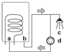
flowchart
graph TD
    A["Coil"] --> B["Shower Head"]
    B --> C["Valve"]
    C --> D["Pressure Gauge"]
    D --> E["Flow Indicator"]
    style A fill:#f9f,stroke:#333
    style B fill:#ccf,stroke:#333
    style C fill:#cfc,stroke:#333
    style D fill:#fcc,stroke:#333
a Recirculation connection
b Hot water connection
c Shower
d Recirculation pump
7.1.2 Formula to calculate the expansion vessel pre-pressure
The pre-pressure (Pg) of the vessel depends on the installation height difference (H):
$$ \mathrm{Pg} = 0. 3 + (\mathrm{H} / 1 0) (\text { bar }) $$
7.1.3 To check the water volume and flow rate
The indoor unit has an expansion vessel of 10 litre with a factory-set pre-pressure of 1 bar.
To make sure that the unit operates properly:
- You must check the minimum and maximum water volume.
- You might need to adjust the pre-pressure of the expansion vessel.
Minimum water volume
Check that the total water volume in the installation is minimum 20 litres, the internal water volume of the outdoor unit NOT included.

INFORMATION
In critical processes, or in rooms with a high heat load, extra water might be required.

NOTICE
When circulation in each space heating/cooling loop is controlled by remotely controlled valves, it is important that the minimum water volume is guaranteed, even if all of the valves are closed.
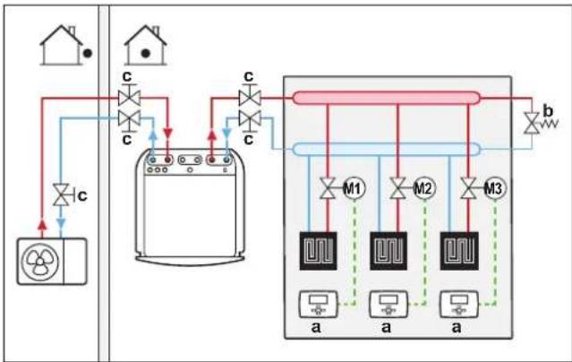
flowchart
graph TD
    A["House"] --> B["Refrigerator"]
    C["House"] --> D["Refrigerator"]
    B --> E["Refrigerator"]
    D --> E
    E --> F["Refrigerator"]
    G["Refrigerator"] --> H["M1"]
    G --> I["M2"]
    G --> J["M3"]
    H --> K["a"]
    I --> L["a"]
    J --> M["a"]
a Individual room thermostat (optional)
b Overpressure bypass valve (delivered as accessory)
c Shut-off valve
Maximum water volume

NOTICE
The maximum water volume depends on whether glycol is added to the water circuit. For more information on the addition of glycol, refer to "7.2.6 To protect the water circuit against freezing" [▶ 83].
Use the following graph to determine the maximum water volume for the calculated pre-pressure.
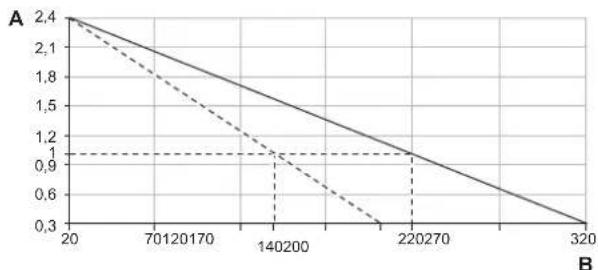
line
| x | Solid Line | Dashed Line | | ------ | ---------- | ----------- | | 20 | 2.4 | 2.4 | | 70120170 | 2.1 | 1.8 | | 140200 | 1.8 | 1.2 | | 220270 | 1.5 | 0.6 | | 320 | 1.2 | 0.3 |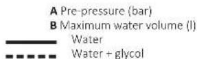
Example: Maximum water volume and expansion vessel pre-pressure
| Installation height difference(a) | Water volume | |
| ≤200 l >200 l | ||
| ≤7 m No pre-pressure adjustment is required. | Do the following: ·Decrease the pre-pressure according to the required installation height difference. The pre-pressure should decrease by 0.1 bar for each metre below 7 m. ·Check if the water volume does NOT exceed the maximum allowed water volume. | |
| >7 m Do the following: ·Increase the pre-pressure according to the required installation height difference. The pre-pressure should increase by 0.1 bar for each metre above 7 m. ·Check if the water volume does NOT exceed the maximum allowed water volume. | The expansion vessel of the indoor unit is too small for the installation. In this case, it is recommended to install an extra vessel outside the unit. | |
^(4) This is the height difference (m) between the highest point of the water circuit and the indoor unit. If the indoor unit is at the highest point of the installation, the installation height is 0 m.
Minimum flow rate
Check that the minimum flow rate in the installation is guaranteed in all conditions. This minimum flow rate is required during defrost/backup heater operation. For this purpose, use the overpressure bypass valve delivered with the unit, and respect the minimum water volume.

NOTICE
To guarantee proper operation it is recommended to have a minimum flow of 28 l/min during DHW.

NOTICE
If glycol was added to the water circuit, and the temperature of the water circuit is low, the flow rate will NOT be displayed on the user interface. In this case, the minimum flow rate can be checked by way of the pump test (check that the user interface does NOT display error 7H).

NOTICE
When circulation in each or certain space heating loops is controlled by remotely controlled valves, it is important that the minimum flow rate is guaranteed, even if all valves are closed. In case the minimum flow rate cannot be reached, a flow error 7H will be generated (no heating or operation).
Minimum required flow rate
25 l/min
See the recommended procedure as described in "10.4 Checklist during commissioning" [▶ 201].
7.1.4 Changing the pre-pressure of the expansion vessel

NOTICE
Only a licensed installer may adjust the pre-pressure of the expansion vessel.
The default pre-pressure of the expansion vessel is 1 bar. When it is required to change the pre-pressure, take following guidelines into account:
- Only use dry nitrogen to set the expansion vessel pre-pressure.
- Inappropriate setting of the expansion vessel pre-pressure will lead to malfunction of the system.
Changing the pre-pressure of the expansion vessel should be done by releasing or increasing nitrogen pressure through the Schrader valve of the expansion vessel.
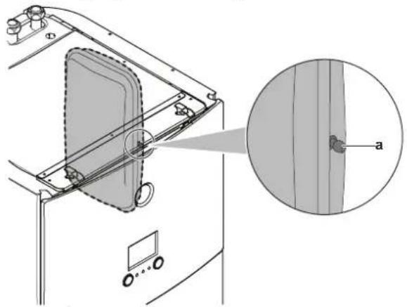
natural_image
Technical diagram of a device with a close-up inset showing a component labeled 'a' (no text or symbols present)a Schrader valve
7.1.5 To check the water volume: Examples
Example 1
The indoor unit is installed 5 m below the highest point in the water circuit. The total water volume in the water circuit is 100 l.
No actions or adjustments are required.
Example 2
The indoor unit is installed at the highest point in the water circuit. The total water volume in the water circuit is 250 l.
Actions:
- Because the total water volume (250 l) is more than the default water volume (200 l), the pre-pressure must be decreased.
- The required pre-pressure is: Pg = (0.3 + (H/10)) bar = (0.3 + (0/10)) bar = 0.3 bar
- The corresponding maximum water volume at 0.3 bar is 290 l. (See the graph in "Maximum water volume" [▶ 77]).
- Because 250 l is lower than 290 l, the expansion vessel is appropriate for the installation.
7.2 Connecting water piping
7.2.1 About connecting the water piping
Before connecting the water piping
Make sure the outdoor and indoor unit are mounted.
Typical workflow
Connecting the water piping typically consists of the following stages:
1 Connecting the water piping to the outdoor unit.
2 Connecting the water piping to the indoor unit.
3 Connecting the recirculation piping.
4 Connecting the drain hose to the drain.
5 Filling the water circuit.
6 Filling the domestic hot water tank.
7 Insulating the water piping.
7.2.2 Precautions when connecting the water piping

INFORMATION
Also read the precautions and requirements in the following chapters:
- "1 General safety precautions" [▶ 6]
- "7.1 Preparing water piping" [▶ 74]
7.2.3 To connect the water piping

NOTICE
Do NOT use excessive force when connecting the field piping and make sure the piping is aligned properly. Deformation of the piping can cause malfunctioning of the unit.
Outdoor unit
1 Connect the shut-off valve (with integrated filter) to the outdoor unit water inlet, using thread sealant.
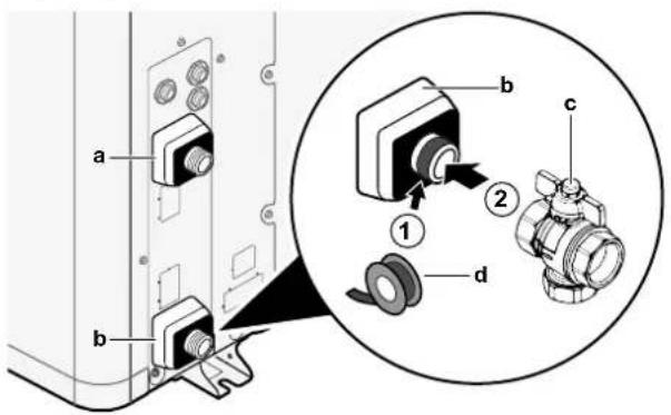
a Water OUT (screw connection, male, 1")
b Water IN (screw connection, male, 1")
c Shut-off valve with integrated filter (delivered as accessory)(2× screw connection, female, 1") d Thread sealant
2 Connect the field piping to the shut-off valve.
3 Connect the field piping to the outdoor unit water outlet.

NOTICE
About the shut-off valve with integrated filter (delivered as accessory):
The installation of the valve at the water inlet is mandatory.
- Mind the flow direction of the valve.

NOTICE
Install air purge valves at all local high points.
Indoor unit
1 Connect the O-rings and shut-off valves to the outdoor unit water connection pipes of the indoor unit.
2 Connect the outdoor unit field piping to the shut-off valves.
3 Connect the O-rings and shut-off valves to the space heating/cooling water pipes of the indoor unit.
4 Connect the space heating/cooling field piping of both zones to the shut-off valves.
5 Connect the domestic hot water in and out pipes to the indoor unit.
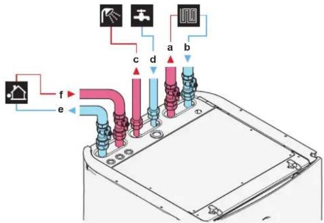
a Space heating/cooling water OUT (screw connection, 1")
b Space heating/cooling water IN (screw connection, 1")
c Domestic hot water OUT (screw connection, 3/4")
d Domestic cold water IN (cold water supply)(screw connection, 3/4")
e Outdoor unit water OUT (screw connection, 1")
f Outdoor unit water IN (screw connection, 1")

NOTICE
It is recommended to install shut-off valves to domestic cold water in and domestic hot water out connections. These shut-off valves are field supplied.

NOTICE
To avoid damage to the surroundings in case of water leakage, it is recommended to close the domestic cold water inlet shut-off valves during periods of absence.

NOTICE

Overpressure bypass valve (delivered as accessory). We recommend to install the overpressure bypass valve in the space heating water circuit.
- Mind the minimum water volume when choosing the installation location of the overpressure bypass valve (at the indoor unit, or at the collector). See "7.1.3 To check the water volume and flow rate" [▶ 76].
- Mind the minimum flow rate when adjusting the overpressure bypass valve setting. See "7.1.3 To check the water volume and flow rate" [▶ 76] and "10.4.1 Minimum flow rate" [▶ 201].

NOTICE
Install air purge valves at all local high points.

NOTICE
A pressure relief valve (field supply) with an opening pressure of maximum 10 bar (=1 MPa) must be installed on the domestic cold water inlet connection in accordance with the applicable legislation.

NOTICE
- A drain device and pressure relief device must be installed on the cold water inlet connection of the domestic hot water cylinder.
- To avoid back siphonage, it is recommended to install a non-return valve on the water inlet of the domestic hot water tank in accordance with the applicable legislation.
- It is recommended to install a pressure reducing valve on the cold water inlet in accordance with the applicable legislation.
- An expansion vessel should be installed on the cold water inlet in accordance with the applicable legislation.
It is recommended to install the pressure relief valve on a higher position than the top of the domestic hot water tank. Heating of the domestic hot water tank causes water to expand and without pressure relief valve the water pressure inside the tank can rise above the tank design pressure. Also the field installation (piping, tapping points, etc.) connected to the tank is subjected to this high pressure. To prevent this, a pressure relief valve needs to be installed. The overpressure prevention depends on the correct operation of the field installed pressure relief valve. If this is NOT working correctly, overpressure will deform the tank and water leakage may occur. To confirm good operation, regular maintenance is required.
7.2.4 To connect the recirculation piping
Prerequisite: Only required if you need recirculation in your system.
1 Remove the top panel from the unit, see "6.2.5 To open the indoor unit" [▶ 61].
2 Cut out the rubber grommet on top of the unit, and remove the stop. The recirculation connector is placed below the hole.
3 Route the recirculation piping through the grommet and connect it to the recirculation connector.
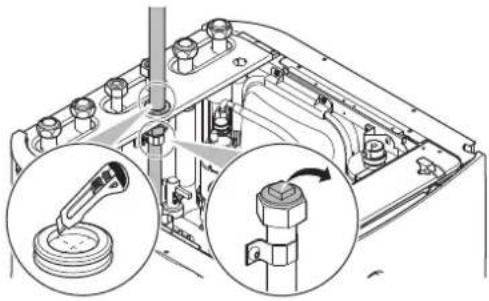
natural_image
Mechanical assembly diagram showing piston and valve components with magnified insets (no text or labels)4 Reattach the top panel.
7.2.5 To fill the water circuit
To fill the water circuit, use a field supply filling kit. Make sure you comply with the applicable legislation.

NOTICE

Make sure both air purge valves (one on the magnetic filter and one on the backup heater) are open.
All automatic air purge valves must remain open after commissioning.
7.2.6 To protect the water circuit against freezing
About freeze protection
Frost can damage the system. To prevent the hydraulic components from freezing, the software is equipped with special frost protection functions, that include the activation of pump in case of low temperatures:
- Water pipe freeze prevention (see "Water pipe freeze prevention" [▶ 182]),
- Drain prevention. Only applicable when Bivalent is enabled ([C-02]=1). This function prevents the opening of freeze protection valves in the water piping to the outdoor unit when the auxiliary boiler is running at negative outdoor temperatures.
However, in case of a power failure, these functions cannot guarantee protection.
Do one of the following to protect the water circuit against freezing:
- Add glycol to the water. Glycol lowers the freezing point of the water.
- Install freeze protection valves. Freeze protection valves drain the water from the system before it can freeze.

NOTICE
If you add glycol to the water, do NOT install freeze protection valves. Possible consequence: Glycol leaking out of the freeze protection valves.
Freeze protection by glycol
About freeze protection by glycol
Adding glycol to the water lowers the freezing point of water.

WARNING
Ethylene glycol is toxic.

WARNING
Due to the presence of glycol, corrosion of the system is possible. Uninhibited glycol will turn acidic under the influence of oxygen. This process is accelerated by the presence of copper and high temperatures. The acidic uninhibited glycol attacks metal surfaces and forms galvanic corrosion cells that cause severe damage to the system. Therefore it is important that:
- the water treatment is correctly executed by a qualified water specialist,
- a glycol with corrosion inhibitors is selected to counteract acids formed by the oxidation of glycols,
- no automotive glycol is used because their corrosion inhibitors have a limited lifetime and contain silicates which can foul or plug the system,
- galvanized pipes are NOT used in glycol systems since the presence may lead to the precipitation of certain components in the glycol's corrosion inhibitor.

NOTICE
Glycol absorbs water from its environment. Therefore do NOT add glycol that has been exposed to air. Leaving the cap off the glycol container causes the concentration of water to increase. The glycol concentration is then lower than assumed. As a result, the hydraulic components might freeze up after all. Take preventive actions to ensure a minimal exposure of the glycol to air.
Types of glycol
The types of glycol that can be used depend on whether the system contains a domestic hot water tank:
| If... Then... | |
| The system contains a domestic hot water tank | Only use propylene glycol(a) |
| The system does NOT contain a domestic hot water tank | You can use either propylene glycol(a) or ethylene glycol |
(a) Propylene glycol, including the necessary inhibitors, classified as Category III according to EN1717.
Required concentration of glycol
The required concentration of glycol depends on the lowest expected outdoor temperature, and on whether you want to protect the system from bursting or from freezing. To prevent the system from freezing, more glycol is required.
Add glycol according to the table below.
| Lowest expected outdoor temperature | Prevent from bursting Prevent from freezing |
| -5°C 10% 15% | |
| -10°C 15% 25% | |
| -15°C 20% 35% | |
| -20°C 25% — | |
| -25°C 30% — | |
| -30°C 35% — |

INFORMATION
- Protection against bursting: the glycol will prevent the piping from bursting, but NOT the liquid inside the piping from freezing.
- Protection against freezing: the glycol will prevent the liquid inside the piping from freezing.

NOTICE
- The required concentration might differ depending on the type of glycol. ALWAYS compare the requirements from the table above with the specifications provided by the glycol manufacturer. If necessary, meet the requirements set by the glycol manufacturer.
- The added concentration of glycol should NEVER exceed 35%.
- If the liquid in the system is frozen, the pump will NOT be able to start. Mind that if you only prevent the system from bursting, the liquid inside might still freeze.
- When water is at standstill inside the system, the system is very likely to freeze and get damaged.
Glycol and the maximum allowed water volume
Adding glycol to the water circuit reduces the maximum allowed water volume of the system. For more information, see "Maximum water volume" [▶ 77].
Glycol setting

NOTICE
If glycol is present in the system, setting [E-OD] must be set to 1. If the glycol setting is NOT set correctly, the liquid inside the piping can freeze.
Freeze protection by freeze protection valves
About freeze protection valves
It is the responsibility of the installer to protect the field piping against freezing. When no glycol is added to the water, you can use freeze protection valves at all lowest points of the field piping to drain the water from the system before it can freeze.
To install freeze protection valves
To protect the field piping against freezing, install the following parts:
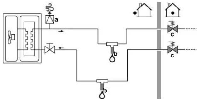
flowchart
graph TD
    A["Power Source"] --> B["Turner"]
    B --> C["Diode a"]
    B --> D["Diode b"]
    C --> E["Branch 1"]
    D --> F["Branch 2"]
    E --> G["Output"]
    F --> H["Output"]
    G --> I["Output"]
    H --> J["Output"]
    style A fill:#f9f,stroke:#333
    style B fill:#ccf,stroke:#333
    style C fill:#cfc,stroke:#333
    style D fill:#fcc,stroke:#333
    style E fill:#ffc,stroke:#333
    style F fill:#fcc,stroke:#333
    style G fill:#cff,stroke:#333
    style H fill:#ffc,stroke:#333
    style I fill:#cfc,stroke:#333
a Automatic air intake
b Freeze protection valve (optional – field supply)
c Normally closed valves (recommended – field supply)
| Part Description | |
| An automatic air intake (for air supply) should be installed at the highest point. For example, an automatic air purge. | |
| [WT24] | Protection for the field piping. The freeze protection valves must be installed:• vertically to allow water to flow out properly and free from obstructions.• at all lowest points of the field piping.• in the coldest part and away from heat sources.Note:Leave at least 15 cm clearance from the ground to prevent ice from blocking the water exit. |
| [WH04] | Isolation of water inside the house when there is a power interruption. Normally closed valves (located indoors near the piping entry/exit points) can prevent that all water from indoor piping is drained when the freeze protection valves open.• When there is a power interruption:The normally closed valves close and isolate the water inside the house. If the freeze protection valves open, only the water outside the house is drained.• In other circumstances (example: when there is a pump failure): The normally closed valves remain open. If the freeze protection valves open, the water from inside the house is also drained. |

NOTICE
When freeze protection valves are installed, do NOT select a minimum cooling setpoint lower than 7^ C ( 7^ C=default). If lower, freeze protection valves can open during cooling operation.
7.2.7 To fill the domestic hot water tank
1 Open every hot water tap in turn to purge air from the system pipe work.
2 Open the cold water supply valve.
3 Close all water taps after all air is purged.
4 Check for water leaks.
7.2.8 To insulate the water piping
The piping in the complete water circuit MUST be insulated to prevent condensation during cooling operation and reduction of the heating and cooling capacity.
Outdoor water piping insulation

NOTICE
Outside piping. Make sure the outside piping is insulated as instructed to protect against hazards.
For piping in free air, it is recommended to use the insulation thickness as shown in below table as a minimum (with =0.039 W/mK).
| Piping length (m) Minimum insulation thickness (mm) | |
| <20 19 | |
| 20~30 32 | |
| 30~40 40 | |
| 40~50 50 | |
For other cases the minimum insulation thickness can be determined using the Hydronic Piping Calculation tool.
The Hydronic Piping Calculation tool also calculates the maximum hydronic piping length from the indoor unit to the outdoor unit based on the emitter pressure drop or the other way around.
The Hydronic Piping Calculation tool is part of the Heating Solutions Navigator which can be reached via https://professional.standbyme.daikin.eu.
Please contact your dealer if you have no access to Heating Solutions Navigator.
This recommendation ensures good operation of the unit, however, local regulations may differ and shall be followed.
8 Electrical installation
In this chapter
8.1 About connecting the electrical wiring 88
8.1.1 Precautions when connecting the electrical wiring 88
8.1.2 Guidelines when connecting the electrical wiring 89
8.1.3 About electrical compliance 90
8.1.4 About preferential kWh rate power supply.... 90
8.1.5 Overview of electrical connections except external actuators 91
8.2 Connections to the outdoor unit 92
8.2.1 To connect the electrical wiring to the outdoor unit 92
8.2.2 To reposition the air thermistor on the outdoor unit 98
8.3 Connections to the indoor unit 99
8.3.1 To connect the main power supply 102
8.3.2 To connect the backup heater power supply 104
8.3.3 To connect the shut-off valve 106
8.3.4 To connect the electricity meters.... 107
8.3.5 To connect the domestic hot water pump 108
8.3.6 To connect the alarm output.... 109
8.3.7 To connect the space cooling/heating ON/OFF output 110
8.3.8 To connect the changeover to external heat source 111
8.3.9 To connect the power consumption digital inputs 112
8.3.10 To connect the safety thermostat (normally closed contact) 113
8.4 After connecting the electrical wiring to the indoor unit 114
8.1 About connecting the electrical wiring
Before connecting the electrical wiring
Make sure the water piping is connected.
Typical workflow
Connecting the electrical wiring typically consists of the following stages:
- "8.2 Connections to the outdoor unit" [▶ 92]
- "8.3 Connections to the indoor unit" [▶ 99]
8.1.1 Precautions when connecting the electrical wiring

DANGER: RISK OF ELECTROCUTION

INFORMATION
Also read the precautions and requirements in the "General safety precautions" chapter.

WARNING
- All wiring MUST be performed by an authorised electrician and MUST comply with the applicable legislation.
■ Make electrical connections to the fixed wiring. - All components procured on-site and all electrical construction MUST comply with the applicable legislation.

WARNING
- If the power supply has a missing or wrong N-phase, equipment might break down.
- Establish proper earthing. Do NOT earth the unit to a utility pipe, surge absorber, or telephone earth. Incomplete earthing may cause electrical shock.
- Install the required fuses or circuit breakers.
- Secure the electrical wiring with cable ties so that the cables do NOT come in contact with sharp edges or piping, particularly on the high-pressure side.
- Do NOT use taped wires, stranded conductor wires, extension cords, or connections from a star system. They can cause overheating, electrical shock or fire.
- Do NOT install a phase advancing capacitor, because this unit is equipped with an inverter. A phase advancing capacitor will reduce performance and may cause accidents.

WARNING
Rotating fan. Before powering ON or servicing the outdoor unit, make sure that the discharge grille covers the fan as protection against a rotating fan. See:
■ "6.3.6 To install the discharge grille" [▶ 68]
- "6.3.7 To remove the discharge grille, and put the grille in safety position" [▶ 69]

CAUTION
Do NOT push or place redundant cable length in the unit.

NOTICE
The distance between the high voltage and low voltage cables should be at least 50 mm.

WARNING
ALWAYS use multicore cable for power supply cables.
8.1.2 Guidelines when connecting the electrical wiring
Keep the following in mind:
- If stranded conductor wires are used, install a round crimp-style terminal on the end of the wire. Place the round crimp-style terminal on the wire up to the covered part and fasten the terminal with the appropriate tool.
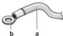
a Stranded conductor wire
b Round crimp-style terminal
- Use the following methods for installing wires:
| Wire type Installation method | |
| Single-core wire | 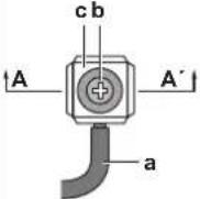 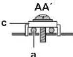 a Curled single-core wireb Screwc Flat washer a Curled single-core wireb Screwc Flat washer |
| Stranded conductor wire with round crimp-style terminal | chbar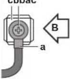 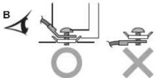 a Terminalb Screwc Flat washerO AllowedX NOT allowed a Terminalb Screwc Flat washerO AllowedX NOT allowed |
Tightening torques
Outdoor unit:
| Item Tightening torque (N•m) | |
| M4 (X1M, X2M) 1.2~1.5 | |
| M4 (earth) | |
Indoor unit:
| Item Tightening torque (N•m) | |
| M4 (X1M, X2M, X5M) 1.2~1.5 | |
| M4 (earth) | |
8.1.3 About electrical compliance
Only for EPRA14\~18DAV3
Equipment complying with EN/IEC 61000-3-12 (European/International Technical Standard setting the limits for harmonic currents produced by equipment connected to public low-voltage systems with input current >16 A and ≤75 A per phase.).
Only for the backup heater of the indoor unit
See "8.3.2 To connect the backup heater power supply" [▶ 104].
8.1.4 About preferential kWh rate power supply
Electricity companies throughout the world work hard to provide reliable electric service at competitive prices and are often authorized to bill clients at benefit rates. E.g. time-of-use rates, seasonal rates, Wärmepumpentarif in Germany and Austria, ...
This equipment allows for connection to such preferential kWh rate power supply delivery systems.
Consult with the electricity company acting as provider at the site where this equipment is to be installed to know whether it is appropriate to connect the equipment in one of the preferential kWh rate power supply delivery systems available, if any.
When the equipment is connected to such preferential kWh rate power supply, the electricity company is allowed to:
- interrupt power supply to the equipment for certain periods of time;
- demand that the equipment only consumes a limited amount of electricity during certain periods of time.
The indoor unit is designed to receive an input signal by which the unit switches into forced off mode. At that moment, the outdoor unit compressor will not operate.
The wiring to the unit is different depending on whether the power supply is interrupted or not.
8.1.5 Overview of electrical connections except external actuators
| Normal power supply Preferential kWh rate power supply | ||
| Power supply is NOT interrupted | Power supply is interrupted | |
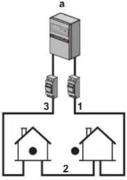 | h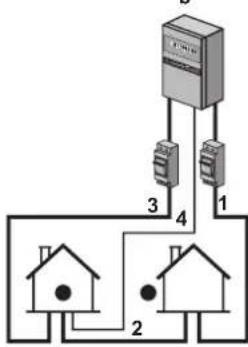 | 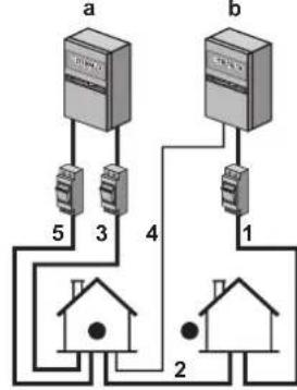 |
| During preferential kWh rate power supply activation, power supply is NOT interrupted. The outdoor unit is turned off by the control.Remark:The electricity company must always allow the power consumption of the indoor unit. | During preferential kWh rate power supply activation, power supply is interrupted immediately or after some time by the electricity company. In this case, the indoor unit must be powered by a separate normal power supply. | |
a Normal power supply
b Preferential kWh rate power supply
1 Power supply for outdoor unit
2 Power supply and interconnection cable to indoor unit
3 Power supply for backup heater
4 Preferential kWh rate power supply (voltage free contact)
5 Normal kWh rate power supply (to power the indoor unit PCB in the event of power supply interruption of the preferential kWh rate power supply)
8.2 Connections to the outdoor unit
| Item Description | |
| Power supply cable See "8.2.1 To connect the electrical wiring to the outdoor unit" [▶ 92]. | |
| Interconnection cable | |
| Drain tube heater cable | |
| Connection for power saving function (only for V3 models) | |
| Air thermistor cable See "8.2.2 To reposition the air thermistor on the outdoor unit" [▶ 98]. | |
8.2.1 To connect the electrical wiring to the outdoor unit
1 Open the switch box cover. See "6.2.2 To open the outdoor unit" [▶ 59].
2 Strip insulation (20 mm) from the wires.
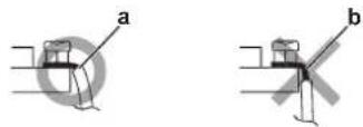
a Strip wire end to this point
b An excessive strip length may cause electrical shock or leakage
3 Insert the cables at the back of the unit, and route them through the factory-mounted cable sleeves into the switch box. For the power supply, use the factory-mounted cable.
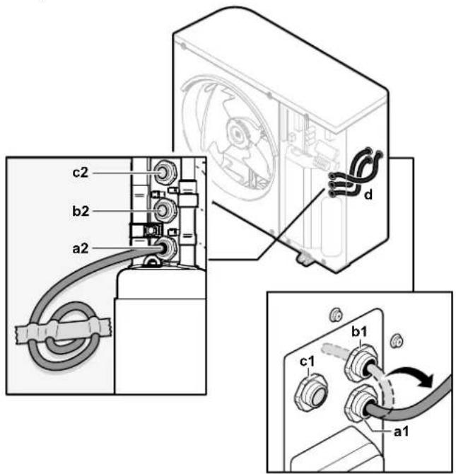
a1+a2 Power supply cable (factory-mounted cable)
b1+b2 Interconnection cable (field supply)
c1+c2 (optional) Drain tube heater cable (field supply)
d Cable sleeves (factory-mounted)
4 Inside the switch box, connect the wires to the appropriate terminals, and fix the cables with cable ties. See:
- "In case of V3 models" [▶ 93]
- "In case of W1 models" [▶ 95]
In case of V3 models
1 Power supply cable:
- Use the factory-mounted cable, which is already routed through the frame.
- Connect the wires to the terminal block.
- Fix the cable with a cable tie.

Use the factory-mounted cable.
Wires: 1N+GND
Maximum running current: Refer to name plate on unit.

一
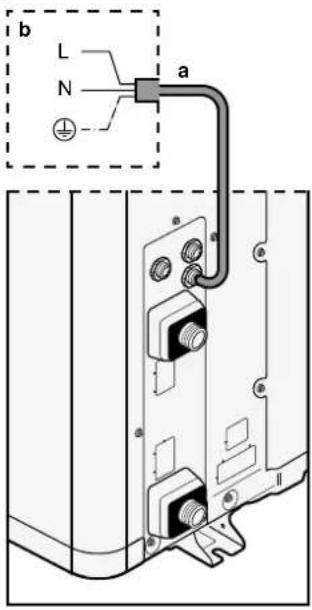
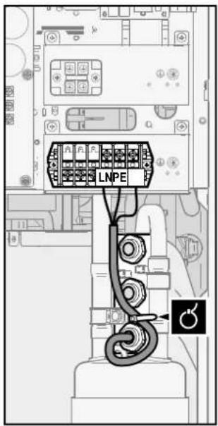
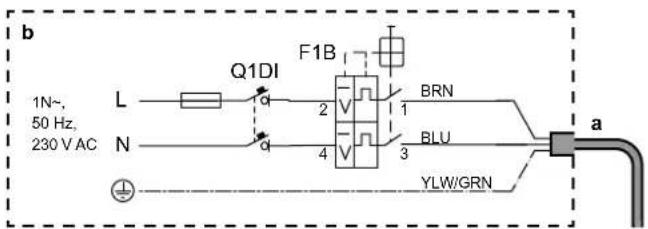
a Factory-mounted power supply cable
b Field wiring
F1B Overcurrent fuse (field supply). Recommended fuse: 2 pole, 32 A fuse, C curve.
Q1DI Earth leakage circuit breaker (30 mA)(field supply)
2 Interconnection cable (indoor↔outdoor):
- Route the cable through the frame.
- Connect the wires to the terminal block (make sure the numbers match with the numbers on the indoor unit) and the earth screw.
- Fix the cable with a cable tie.

Wires: (3+GND)×1.5 mm²


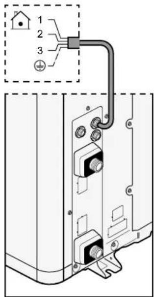
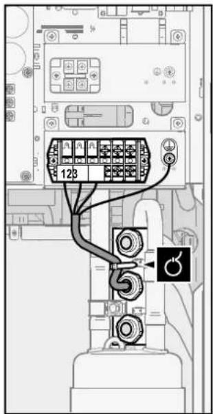
3 (Optional) Drain tube heater cable:
- Make sure the heating element of the drain tube heater is completely inside the drain tube.
- Route the cable through the frame.
- Connect the wires to the terminal block and the earth screw.
- Fix the cable with cable ties.

Wires: (2+GND)×0.75 mm². Wiring must be double insulated.
Maximum power allowed for drain tube heater = 115 W (0.5 A)


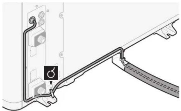
natural_image
Technical diagram showing a mechanical assembly with a bracket and mounting components (no text or symbols)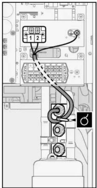
4 (Optional) Power saving function: If you want to use the power saving function:
- Disconnect X804A from X805A.
- Connect X804A to X806A.
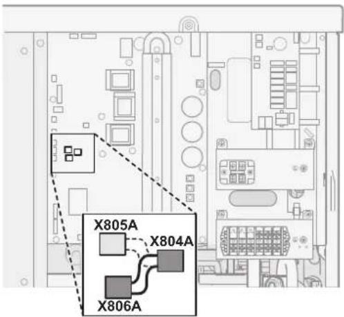

INFORMATION
Power saving function. The power saving function is only applicable for V3 models. For more information about the power saving function ([9.F] or overview field setting [E-08]), see "Power saving function" [▶ 192].
In case of W1 models
1 Power supply cable:
- Use the factory-mounted cable, which is already routed through the frame.
- Connect the wires to the terminal block.
- Fix the cable with a cable tie.

Use the factory-mounted cable.
Wires: 3N+GND
Maximum running current: Refer to name plate on unit.

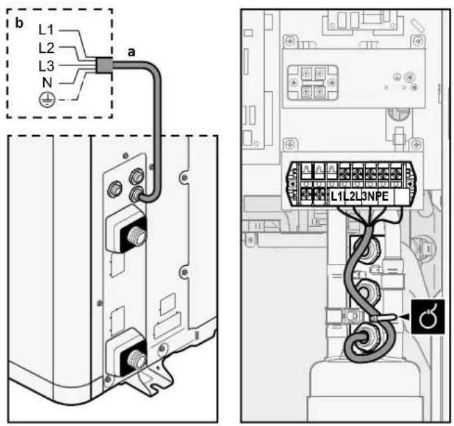
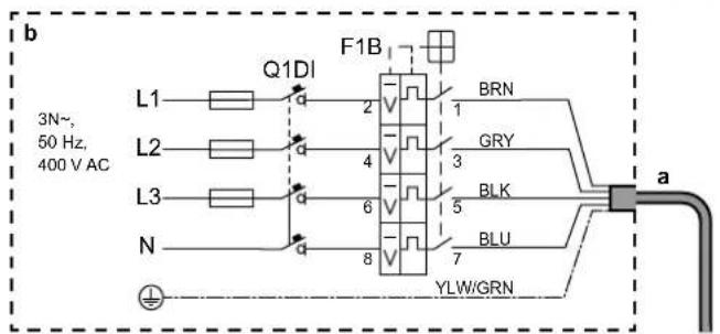
a Factory-mounted power supply cable
b Field wiring
F1B Overcurrent fuse (field supply). Recommended fuse: 4 pole, 16 A or 20 A fuse, C curve.
Q1DI Earth leakage circuit breaker (30 mA)(field supply)
2 Interconnection cable (indoor↔outdoor):
- Route the cable through the frame.
- Connect the wires to the terminal block (make sure the numbers match with the numbers on the indoor unit) and the earth screw.
- Fix the cable with a cable tie.
| Wires: (3+GND)×1.5 mm2 | |
| — |
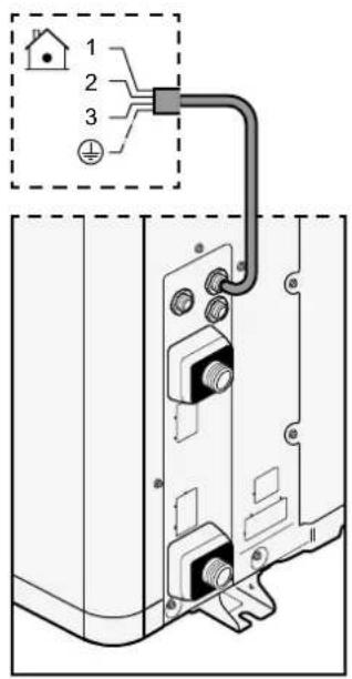
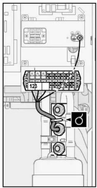
3 (Optional) Drain tube heater cable:
- Make sure the heating element of the drain tube heater is completely inside the drain tube.
- Route the cable through the frame.
- Connect the wires to the terminal block and the earth screw.
- Fix the cable with cable ties.
| Wires: (2+GND)×0.75 mm2. Wiring must be double insulated.Maximum power allowed for drain tube heater = 115 W (0.5 A) | |
| — |
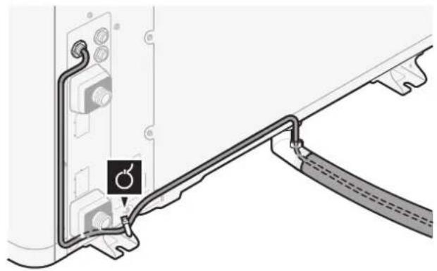
natural_image
Technical diagram showing a mechanical assembly with a labeled component (no text or symbols present)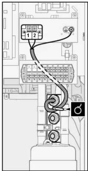
8.2.2 To reposition the air thermistor on the outdoor unit
This procedure is only necessary in areas with low ambient temperatures.
Required accessory (delivered with the unit):
Thermistor fixture.
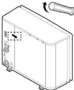
natural_image
Line drawing of a rectangular electronic device with a button and a cylindrical component on top (no text or symbols)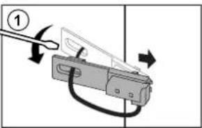
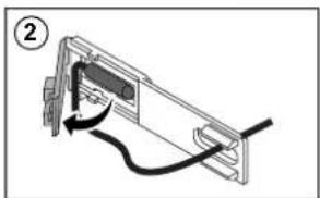
natural_image
Diagram of a computer monitor with cable and indicator lights, no text or symbols present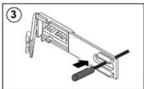
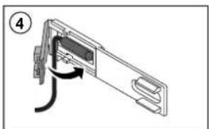
natural_image
Diagram of a mechanical assembly with a component being inserted, showing a curved arrow indicating rotation (no text or symbols present)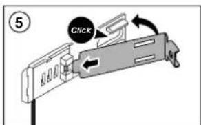
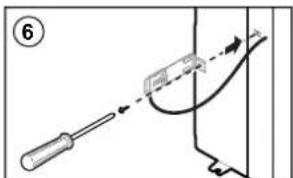
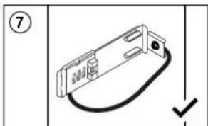
natural_image
Simple line drawing of a device with a cable and connector (no text or symbols)8.3 Connections to the indoor unit
| Item Description | ||
| Power supply (main) See "8.3.1 To connect the main power supply" [▶ 102]. | ||
| Power supply (backup heater) | See "8.3.2 To connect the backup heater power supply" [▶ 104]. | |
| Shut-off valve | See "8.3.3 To connect the shut-off valve" [▶ 106]. | |
| Electricity meters | See "8.3.4 To connect the electricity meters" [▶ 107]. | |
| Domestic hot water pump See "8.3.5 To connect the domestic hot water pump" [▶ 108]. | ||
| Alarm output | See "8.3.6 To connect the alarm output" [▶ 109]. | |
| Space cooling/heating operation control | See "8.3.7 To connect the space cooling/heating ON/OFF output" [▶ 110]. | |
| Changeover to external heat source control | See "8.3.8 To connect the changeover to external heat source" [▶ 111]. | |
| Power consumption digital inputs | See "8.3.9 To connect the power consumption digital inputs" [▶ 112]. | |
| Safety thermostat See "8.3.10 To connect the safety thermostat (normally closed contact)" [▶ 113]. | ||
| Room thermostat (wired or wireless) | [DBXX] | See:Installation manual of the wireless room thermostatInstallation manual of the wired room thermostat (digital or analogue) + multi-zoning base unitConnection of the wired room thermostat (digital or analogue) to the multi-zoning base unitConnection of the multi-zoning base unit to the indoor unitFor cooling/heating operation, you also need option EKRELAY1Addendum book for optional equipment |
 | Wires: 0.75 mm2Maximum running current: 100 mA | |
 | For the main zone:[2.9] Control[2.A] Thermostat typeFor the additional zone:[3.A] Thermostat type[3.9] (read-only) Control | |
Heat pump convector There a  | | ferent controllers and setups possible for the heat pump convectors. Depending on the setup, you also need option EKRELAY1. For more information, see: Installation manual of the heat pump convectors Installation manual of the heat pump convector options Addendum book for optional equipment |
 | Wires: 0.75 mm2 Maximum running current: 100 mA | |
 | For the main zone: [2.9] Control [2.A] Thermostat type For the additional zone: [3.A] Thermostat type [3.9] (read-only) Control | |
| Remote outdoor sensor See: |  | Installation manual of the remote outdoor sensor Addendum book for optional equipment |
 | Wires: 2×0.75 mm2 | |
 | [9.B.1]=1 (External sensor = Outdoor) [9.B.2] Ext. amb. sensor offset [9.B.3] Averaging time | |
| Remote indoor sensor See: |  | Installation manual of the remote indoor sensor Addendum book for optional equipment |
 | Wires: 2×0.75 mm2 | |
 | [9.B.1]=2 (External sensor = Room) [1.7] Room sensor offset | |
| Human Comfort Interface See | Installation and operation manual of the Human Comfort InterfaceAddendum book for optional equipment | |
| Wires: 2×(0.75~1.25 mm2)Maximum length: 500 m | ||
| [2.9] Control[1.6] Room sensor offset | ||
| WLAN adapter See: | Installation manual of the WLAN adapterAddendum book for optional equipment | |
| Use the cable delivered with the WLAN adapter. | ||
| [D] Wireless gateway | ||
| LAN adapter See: | Installation manual of the LAN adapterAddendum book for optional equipment | |
| Wires: 2×(0.75~1.25 mm2). Must be sheathed.Maximum length: 200 m | ||
| See below ("LAN adapter – System requirements"). | ||
LAN adapter – System requirements
The requirements posed on the system depend on the LAN adapter application/system layout (app control, or Smart Grid application).
App control:
| Item Requirement | |
| LAN adapter software It is recommended to ALWAYS keep the LAN adapter software up-to-date. | |
| Unit control method On the user interface, make sure to set [2.9]=2 (Control = Room thermostat) |
Smart Grid application:
| Item Requirement | |
| LAN adapter software It is re | recommended to ALWAYS keep the LAN adapter software up-to-date. |
| Unit control method On the user interface, make sure to set [2.9]=2 (Control = Room thermostat) | |
| Domestic hot water settings | To allow for energy buffering in the domestic hot water tank, on the user interface, make sure to set [9.2.1]=4 (Domestic hot water = Integrated). |
| Power consumption control settings | On the user interface, make sure to set:▪ [9.9.1]=1 (Power consumption control = Continuous)▪ [9.9.2]=1 (Type = kW) |
main power supply
1 Open the following (see "6.2.5 To open the indoor unit" [▶ 61]):
| 1 Top panel | |
| 2 User interface panel | |
| 3 Upper switch box cover |
2 Connect the main power supply.
In case of normal kWh rate power supply
 | Interconnection cable (= main power supply) | Wires: (3+GND)×1.5 mm2 |
 | — | |
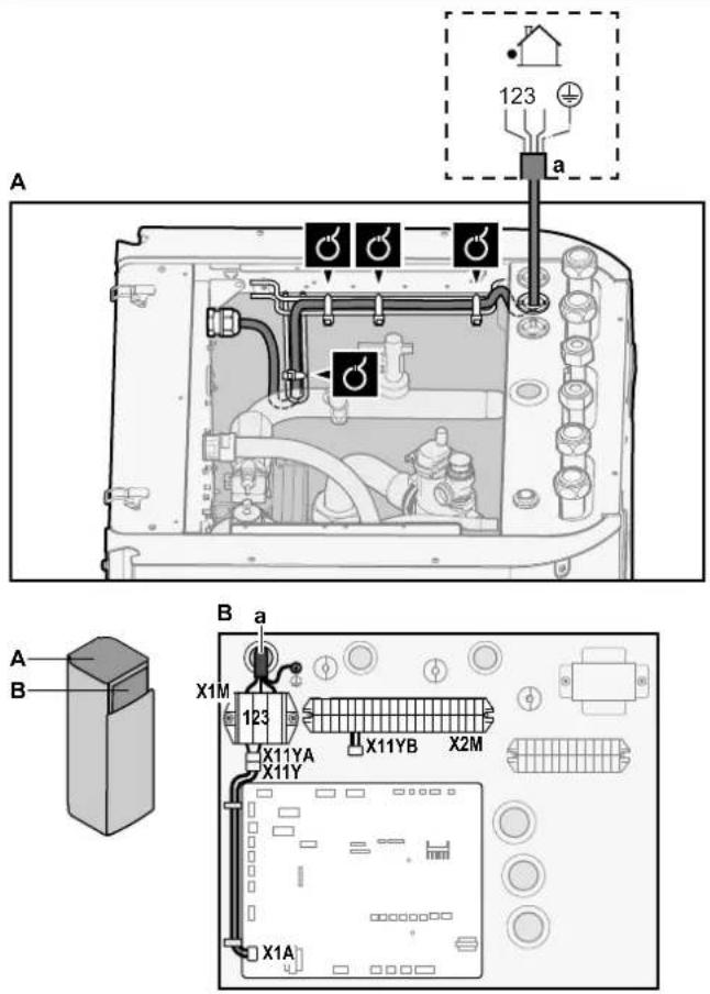
a Interconnection cable (=main power supply)
In case of preferential kWh rate power supply
 | Interconnection cable (= main power supply) | Wires: (3+GND)×1.5 mm2 |
| Normal kWh rate power supply | Wires: 1NMaximum running current: 6.3 A | |
| Preferential kWh rate power supply contact | Wires: 2×(0.75~1.25 mm2)Maximum length: 50 m.Preferential kWh rate power supply contact: 16 V DC detection (voltage supplied by PCB). The voltage-free contact shall ensure the minimum applicable load of 15 V DC, 10 mA. | |
 | [9.8] Benefit kWh power supply | |
Connect X11Y to X11YB.
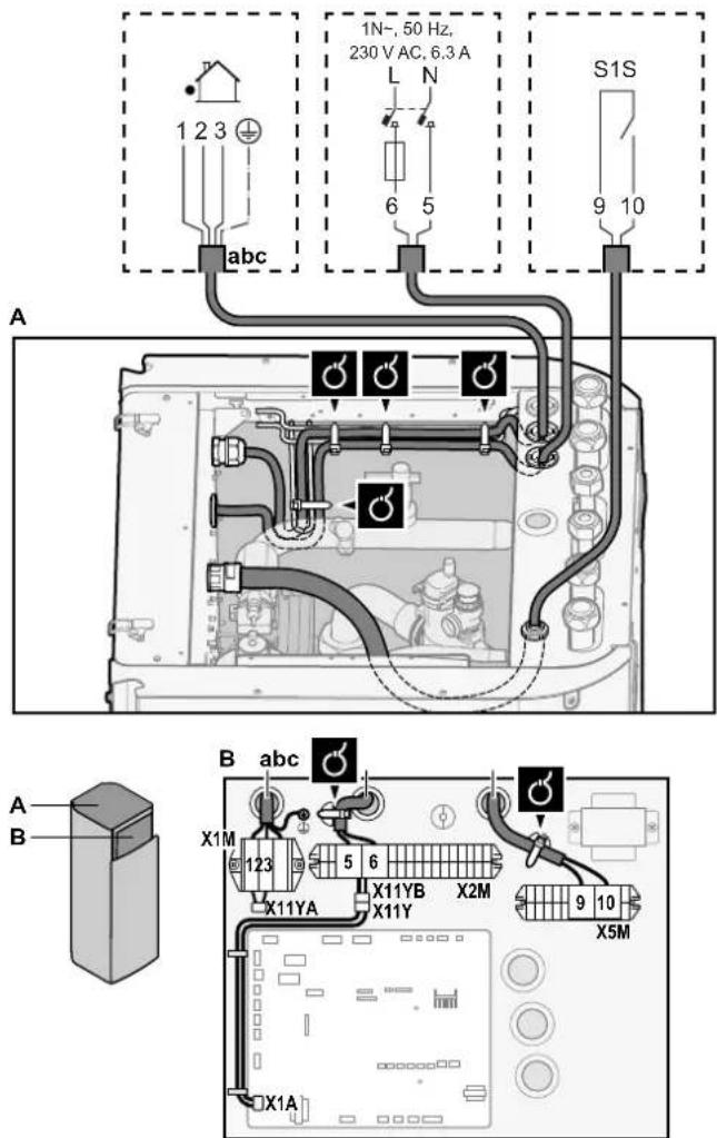
a Interconnection cable (=main power supply)
b Normal kWh rate power supply
c Preferential power supply contact
3 Fix the cables with cable ties to the cable tie mountings.

INFORMATION
In case of preferential kWh rate power supply, connect X11Y to X11YB. The necessity of separate normal kWh rate power supply to indoor unit (b) X2M/5+6 depends on the type of preferential kWh rate power supply.
Separate connection to the indoor unit is required:
■ if preferential kWh rate power supply is interrupted when active, OR
- if no power consumption of the indoor unit is allowed at the preferential kWh rate power supply when active.

INFORMATION
The preferential kWh rate power supply contact is connected to the same terminals (X5M/9+10) as the safety thermostat. Thus, the system can have EITHER preferential kWh rate power supply OR a safety thermostat.
8.3.2 To connect the backup heater power supply

Backup heater type Power supply Wires
| *6V 1N~230 V (6V) 2+GND | |||
| 3~230 V (6T1) 3+GND | |||
| *9W 3N~400 V 4+GND | |||
| [7x2T] | [9.3] Backup heater | ||

WARNING
The backup heater MUST have a dedicated power supply and MUST be protected by the safety devices required by the applicable legislation.

CAUTION
To guarantee the unit is completely earthed, always connect the backup heater power supply and the earth cable.
The backup heater capacity can vary, depending on the indoor unit model. Make sure that the power supply is in accordance with the backup heater capacity, as listed in the table below.
| Backup heater type | Backup heater capacity | Power supply | Maximum running current | Z_max |
| *6V 2 kW 1N~ 230 V | (a) | 9 A | — | |
| 4 kW 1N~ | 230 V (a) | 17 A^(b)(c) | 0.22 Ω | |
| 6 kW 1N~ | 230 V (a) | 26 A^(b)(c) | 0.22 Ω | |
| 2 kW | 3~ 230 V^(d) | 5 A | — | |
| 4 kW | 3~ 230 V^(d) | 10 A | — | |
| 6 kW | 3~ 230 V^(d) | 15 A | — | |
| *9W | 3 kW | 3N~ 400 V | 4 A | — |
| 6 kW | 3N~ 400 V | 9 A | — | |
| 9 kW | 3N~ 400 V | 13 A | — |
(a) 6V
(b) Electrical equipment complying with EN/IEC 61000-3-12 (European/International Technical Standard setting the limits for harmonic currents produced by equipment connected to public low-voltage systems with input current >16 A and ≤75 A per phase).
(i) This equipment complies with EN/IEC 61000-3-11 (European/International Technical Standard setting the limits for voltage changes, voltage fluctuations and flicker in public low-voltage supply systems for equipment with rated current ≤75 A) provided that the system impedance Z_sys is less than or equal to Z_max at the interface point between the user's supply and the public system. It is the responsibility of the installer or user of the equipment to ensure, by consultation with the distribution network operator if necessary, that the equipment is connected only to a supply with a system impedance Z_sys less than or equal to Z_max .
(d) 6T1
Connect the backup heater power supply as follows:
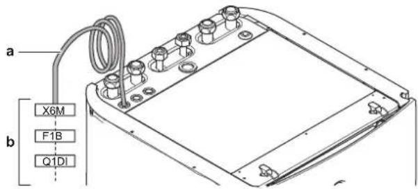
a Factory-mounted cable connected to the contactor of the backup heater, inside the switch box (KSM) b Field wiring (see table below)
| Model (power supply) Connections to backup heater power supply | ||
| *6V (6V: 1N~ 230 V) | 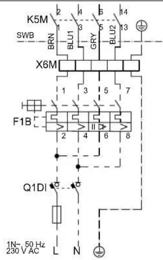 | |
| *6V (6T1: 3~ 230 V) | 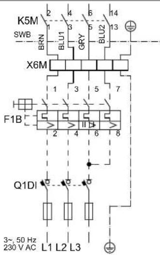 | |
Model (power supply) Connections to backup heater power supply
*9W (3N\~ 400 V)
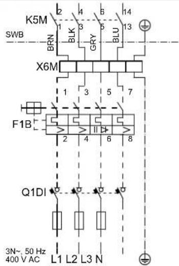
F1B Overcurrent fuse (field supply). Recommended fuse: 4-pole; 20 A; curve 400 V; tripping class C.
K5M Safety contactor (in the lower switch box)
Q1DI Earth leakage circuit breaker (field supply)
SWB Switch box
X6M Terminal (field supply)

NOTICE
Do NOT cut or remove the backup heater power supply cable.
8.3.3 To connect the shut-off valve

INFORMATION
Shut-off valve usage example. In case of one LWT zone, and a combination of underfloor heating and heat pump convectors, install a shut-off valve before the underfloor heating to prevent condensation on the floor during cooling operation. For more information, see the installer reference guide.

Wires: 2×0.75 mm²
Maximum running current: 100 mA
230 V AC supplied by PCB

[2.D] Shut off valve
1 Open the following (see "6.2.5 To open the indoor unit" [▶ 61]):
| 1 Top panel | ![DAIKIN ETVX16S18DA9W - Open the following (see "6.2.5 To open the indoor unit" [▶ 61]): - 1](/content/2026/05/911660/images/14a8798403888d04499e3d16b2378694fcddea193ed88262ae17cb2cc478b020.jpg) |
| 2 User interface panel | |
| 3 Upper switch box cover |
2 Connect the valve control cable to the appropriate terminals as shown in the illustration below.
![DAIKIN ETVX16S18DA9W - Open the following (see "6.2.5 To open the indoor unit" [▶ 61]): - 2](/content/2026/05/911660/images/a38e31f2feffe3f6f3a14c0f94439537112ba42fc3815990897e35e1d8d75c2a.jpg)
NOTICE
Wiring is different for a NC (normally closed) valve and a NO (normally open) valve.
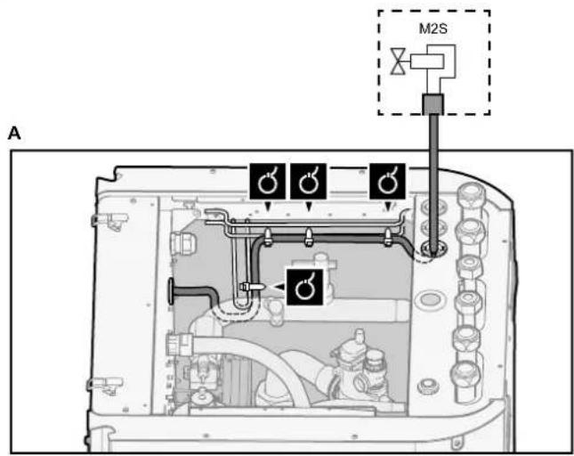
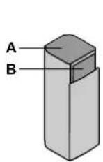
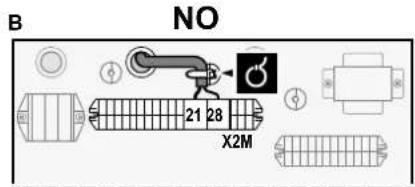
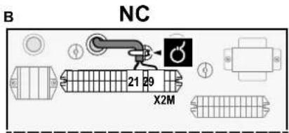
3 Fix the cable with cable ties to the cable tie mountings.
8.3.4 To connect the electricity meters
| Wires: 2 (per meter)×0.75 mm ^2 Electricity meters: 12 V DC pulse detection (voltage supplied by PCB) | |
| [9.A] Energy metering |

INFORMATION
In case of an electricity meter with transistor output, check the polarity. The positive polarity MUST be connected to X5M/6 and X5M/4; the negative polarity to X5M/5 and X5M/3.
1 Open the following (see "6.2.5 To open the indoor unit" [▶ 61]):
| 1 | Top panel |  |
| 2 | User interface panel | |
| 3 | Upper switch box cover |
2 Connect the electricity meters cable to the appropriate terminals as shown in the illustration below.
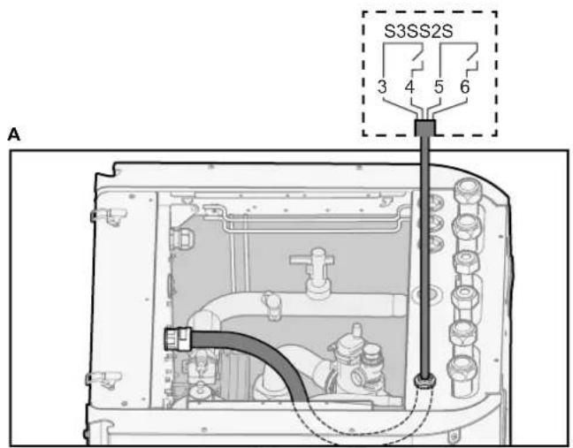
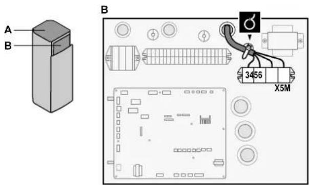
3 Fix the cable with cable ties to the cable tie mountings.
8.3.5 To connect the domestic hot water pump
 | Wires: (2+GND)×0.75 mm ^2 DHW pump output. Maximum load: 2 A (inrush), 230 V AC, 1 A (continuous) |
 | [9.2.2] DHW pump[9.2.3] DHW pump schedule |
1 Open the following (see "6.2.5 To open the indoor unit" [▶ 61]):
| 1 | Top panel | 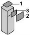 |
| 2 | User interface panel | |
| 3 | Upper switch box cover |
2 Connect the domestic hot water pump cable to the appropriate terminals as shown in the illustration below.
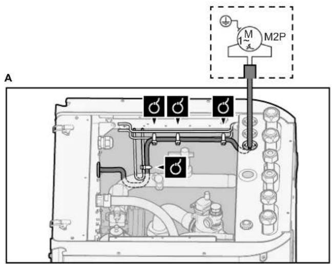
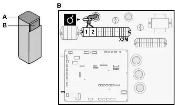
3 Fix the cable with cable ties to the cable tie mountings.
8.3.6 To connect the alarm output
 | Wires: (2+1)×0.75 mm ^2 Maximum load: 0.3 A, 250 V AC |
 | [9.D] Alarm output |
1 Open the following (see "6.2.5 To open the indoor unit" [▶ 61]):
| 1 | Top panel | 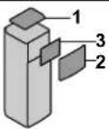 |
| 2 | User interface panel | |
| 3 | Upper switch box cover |
2 Connect the alarm output cable to the appropriate terminals as shown in the illustration below.
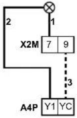 | 1+2 Wires connected to the alarm output |
| 3 Wire between X2M and A4P | |
| A4P Installation of EKRP1HBAA is required. |
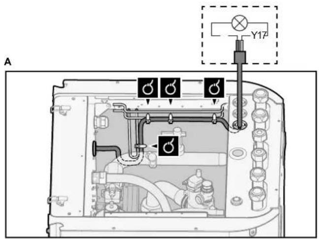
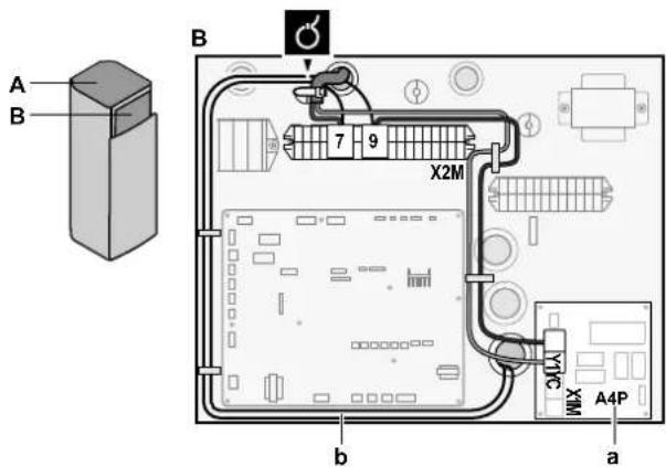
a Installation of EKRP1HBAA is required.
b Prewiring between X2M/7+9 and Q1L (= thermal protector backup heater). Do NOT change.
3 Fix the cable with cable ties to the cable tie mountings.
8.3.7 To connect the space cooling/heating ON/OFF output

INFORMATION
Cooling is only applicable in case of:
■ Reversible models
Heating only models + conversion kit (EKHVCONV2)

Wires: (2+1)×0.75 mm²
Maximum load: 0.3 A, 250 V AC

一
1 Open the following (see "6.2.5 To open the indoor unit" [▶ 61]):
| 1 | Top panel | 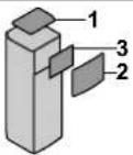 |
| 2 | User interface panel | |
| 3 | Upper switch box cover |
2 Connect the space cooling/heating ON/OFF output cable to the appropriate terminals as shown in the illustration below.
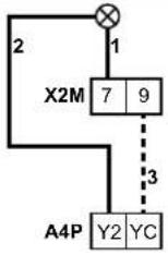 | 1+2 Wires connected to the alarm output |
| 3 Wire between X2M and A4P | |
| A4P Installation of EKRP1HBAA is required. |
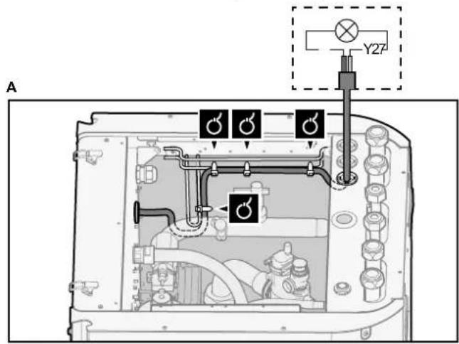
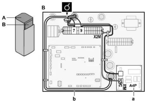
a Installation of EKRP1HBAA is required.
b Prewiring between X2M/7+9 and Q1L (= thermal protector backup heater). Do NOT change.
3 Fix the cable with cable ties to the cable tie mountings.
8.3.8 To connect the changeover to external heat source
 | Wires: 2×0.75 mm ^2 Maximum load: 0.3 A, 250 V ACMinimum load: 20 mA, 5 V DC |
 | [9.C] Bivalent |
1 Open the following (see "6.2.5 To open the indoor unit" [▶ 61]):
| 1 | Top panel | 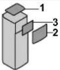 |
| 2 | User interface panel | |
| 3 | Upper switch box cover |
2 Connect the changeover to external heat source cable to the appropriate terminals as shown in the illustration below.
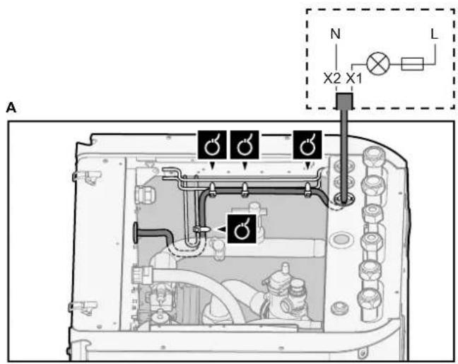
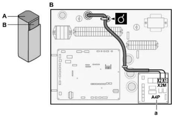
a Installation of EKRP1HBAA is required.
3 Fix the cable with cable ties to the cable tie mountings.
8.3.9 To connect the power consumption digital inputs
 | Wires: 2 (per input signal)×0.75 mm ^2 Power limitation digital inputs: 12 V DC / 12 mA detection (voltage supplied by PCB) |
 | [9.9] Power consumption control. |
1 Open the following (see "6.2.5 To open the indoor unit" [▶ 61]):
 |
2 Connect the power consumption digital inputs cable to the appropriate terminals as shown in the illustration below.
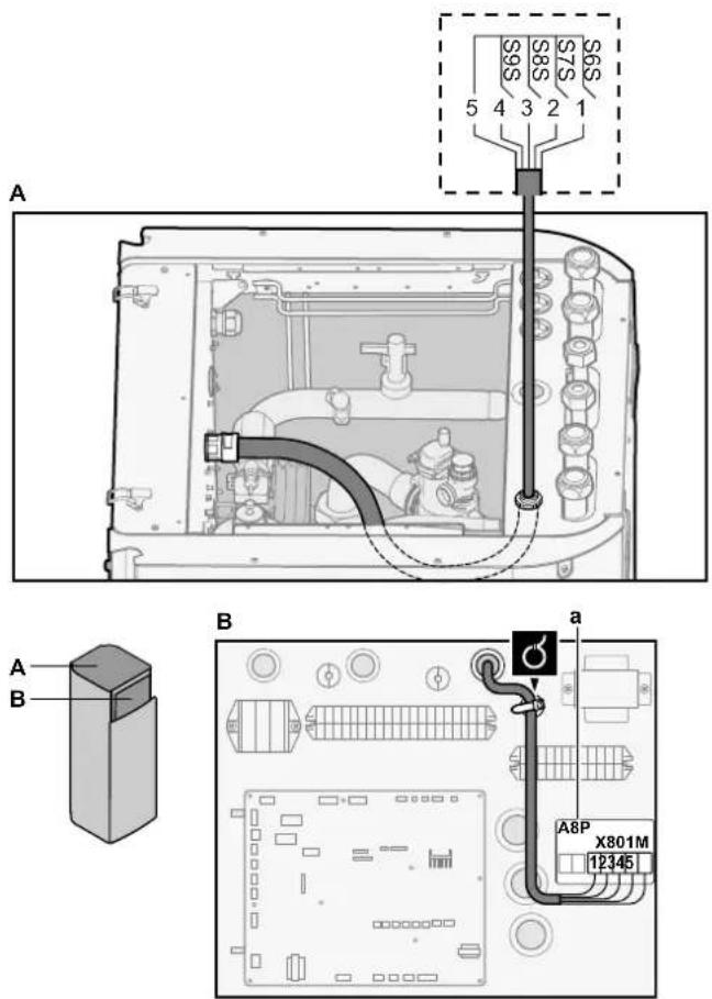
a Installation of EKRP1AHTA is required.
3 Fix the cable with cable ties to the cable tie mountings.
8.3.10 To connect the safety thermostat (normally closed contact)
| [Y6DS] | Wires: 2×0.75 mm ^2 Maximum length: 50 mSafety thermostat contact: 16 V DC detection (voltage supplied by PCB).The voltage-free contact shall ensure the minimum applicable load of 15 V DC, 10 mA. |
 | [9.8.1]=3 (Benefit kWh power supply = Safety thermostat) |
1 Open the following (see "6.2.5 To open the indoor unit" [▶ 61]):
 |
2 Connect the safety thermostat (normally closed) cable to the appropriate terminals as shown in the illustration below.
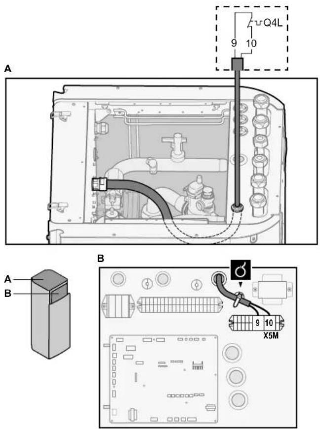
3 Fix the cable with cable ties to the cable tie mountings.

NOTICE
Make sure to select and install the safety thermostat according to the applicable legislation.
In any case, to prevent unnecessary tripping of the safety thermostat, we recommend the following:
The safety thermostat is automatically resettable.
The safety thermostat has a maximum temperature variation rate of 2^ C/min.
- There is a minimum distance of 2 m between the safety thermostat and the 3-way valve.

INFORMATION
ALWAYS configure the safety thermostat after it is installed. Without configuration, the indoor unit will ignore the safety thermostat contact.

INFORMATION
The preferential kWh rate power supply contact is connected to the same terminals (X5M/9+10) as the safety thermostat. Thus, the system can have EITHER preferential kWh rate power supply OR a safety thermostat.
8.4 After connecting the electrical wiring to the indoor unit
To prevent water ingress to the switch box, seal the low voltage wiring intake using the sealing tape (delivered as accessory).
Without low voltage cables With low voltage cables
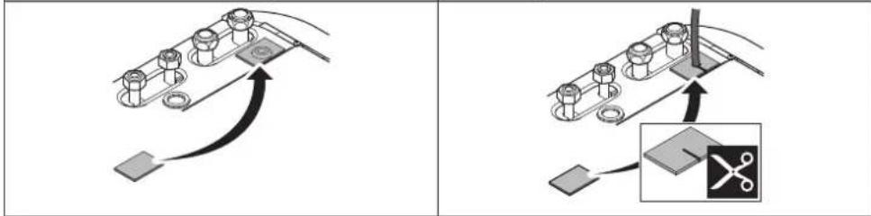
9 Configuration

INFORMATION
Cooling is only applicable in case of:
- Reversible models
- Heating only models + conversion kit (EKHVCONV2)
In this chapter
9.1 Overview: Configuration.... 116
9.1.1 To access the most used commands.... 117
9.2 Configuration wizard 119
9.3 Possible screens.... 120
9.3.1 Possible screens: Overview 120
9.3.2 Home screen 121
9.3.3 Main menu screen 124
9.3.4 Menu screen.... 125
9.3.5 Setpoint screen 125
9.3.6 Detailed screen with values 126
9.3.7 Schedule screen: Example 126
9.4 Weather-dependent curve.... 130
9.4.1 What is a weather-dependent curve? 130
9.4.2 2-points curve....131
9.4.3 Slope-offset curve 132
9.4.4 Using weather-dependent curves 133
9.5 Settings menu 135
9.5.1 Malfunctioning.... 135
9.5.2 Room 136
9.5.3 Main zone 140
9.5.4 Additional zone 149
9.5.5 Space heating/cooling 155
9.5.6 Tank 163
9.5.7 User settings.... 170
9.5.8 Information.... 175
9.5.9 Installer settings 176
9.5.10 Commissioning 194
9.5.11 Operation 194
9.5.12 WLAN adapter 195
9.6 Menu structure: Overview user settings.... 197
9.7 Menu structure: Overview installer settings.... 198
9.1 Overview: Configuration
This chapter describes what you have to do and know to configure the system after it is installed.
Why
If you do NOT configure the system correctly, it might NOT work as expected. The configuration influences the following:
■ The calculations of the software
- What you can see on and do with the user interface
How
You can configure the system via the user interface.
- First time – Configuration wizard. When you turn ON the user interface for the first time (via the indoor unit), the configuration wizard starts to help you configure the system.
- Restart the configuration wizard. If the system is already configured, you can restart the configuration wizard. To restart the configuration wizard, go to Installer settings > Configuration wizard. To access Installer settings, see "9.1.1 To access the most used commands" [▶ 117].
- Afterwards. If necessary, you can make changes to the configuration in the menu structure or the overview settings.

INFORMATION
When the configuration wizard is finished, the user interface will show an overview screen and request to confirm. When confirmed, the system will restart and the home screen will be displayed.
Accessing settings – Legend for tables
You can access the installer settings using two different methods. However, NOT all settings are accessible via both methods. If so, the corresponding table columns in this chapter are set to N/A (not applicable).
| Method Column in tables | |
| Accessing settings via the breadcrumb in the home menu screen or the menu structure. To enable breadcrumbs, press the ?button in the home screen. | #For example: [9.1.5.2] |
| Accessing settings via the code in the overview field settings. | CodeFor example: [C-07] |
See also:
- "To access the installer settings" [▶ 118]
- "9.7 Menu structure: Overview installer settings" [▶ 198]
9.1.1 To access the most used commands
To change the user permission level
You can change the user permission level as follows:
| 1 Go to [B]: User profile. | ### | |
| 2 Enter the applicable pin code for the user permission level. — | ||
| ·Browse through the list of digits and change the selected digit. | ○···· | |
| ·Move the cursor from left to right. | ○···· | |
| ·Confirm the pin code and proceed. | ### | |
Installer pin code
The Installer pin code is 5678. Additional menu items and installer settings are now available.
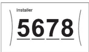
Advanced user pin code
The Advanced user pin code is 1234. Additional menu items for the user are now visible.
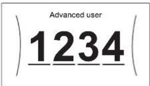
User pin code
The User pin code is 0000.
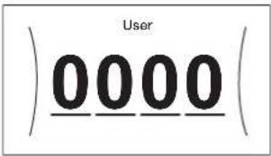
To access the installer settings
1 Set the user permission level to Installer.
2 Go to [9]: Installer settings.
To modify an overview setting
Example: Modify [1-01] from 15 to 20.
Most settings can be configured via the menu structure. If for any reason it is required to change a setting using the overview settings, then the overview settings can be accessed as follows:
| 1 | Set the user permission level to Installer. See "To change the user permission level" [▶ 117]. | — |
| 2 | Go to [9.1]: Installer settings >Overview field settings. | [IMAGE] |
| 3 | Turn the left dial to select the first part of the setting and confirm by pressing the dial.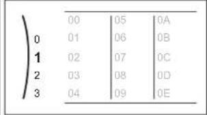 | [IMAGE] |
| 4 | Turn the left dial to select the second part of the setting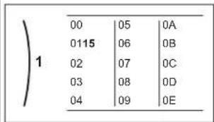 | [IMAGE] |
| 5 | Turn the right dial to modify the value from 15 to 20.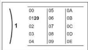 | ○⋯○ |
| 6 P | Press the left dial to confirm the new setting. | |
| 7 P | Press the center button to go back to the home screen. |

INFORMATION
When you change the overview settings and you go back to the home screen, the user interface will show a popup screen and request to restart the system.
When confirmed, the system will restart and recent changes will be applied.
9.2 Configuration wizard
After first power ON of the system, the user interface will guide you using the configuration wizard. This way you can set the most important initial settings. This way the unit will be able to run properly. Afterwards, more detailed settings can be done via the menu structure if required.
You can find a short overview of the settings in the configuration here. All the settings can also be adjusted in the settings menu (use the breadcrumbs).
| For the setting... Refer to... | ||
| Language [7.1] | ||
| Time/date [7.2] | ||
| Hours — | ||
| Minutes | ||
| Year | ||
| Month | ||
| Day | ||
| System | ||
| Indoor unit type (read only) | "9.5.9 Installer settings" [▶ 176] | |
| Backup heater type [9.3.1] | ||
| Domestic hot water [9.2.1] | ||
| Emergency [9.5] | ||
| Number of zones [4.4] "9.5.5 Space heating/cooling" [▶ 155] | ||
| Glycol Filled system (overview field setting [E-0D]) | "9.5.9 Installer settings" [▶ 176] | |
| Booster heater capacity [9.4.1](if applicable) | ||
| Backup heater | ||
| Voltage [9.3.2] | "Backup heater" [▶ 177] | |
| Configuration [9.3.3] | ||
| Capacity step 1 [9.3.4] | ||
| Additional capacity step 2[9.3.5] (if applicable) | ||
| Main zone | ||
| Emitter type [2.7] | "9.5.3 Main zone" [▶ 140] | |
| Control [2.9] | ||
| Setpoint mode [2.4] | ||
| Heating WD curve [2.5] (if applicable) | ||
| Cooling WD curve [2.6] (if applicable) | ||
| Schedule [2.1] | ||
| WD curve type [2.E] | ||
| Additional zone (only if [4.4]=1) | ||
| Emitter type [3.7] | "9.5.4 Additional zone" [▶ 149] | |
| Control (read only) [3.9] | ||
| Setpoint mode [3.4] | ||
| Heating WD curve [3.5] (if applicable) | ||
| Cooling WD curve [3.6] (if applicable) | ||
| Schedule [3.1] | ||
| WD curve type [3.C] (read only) | ||
| Tank | ||
| Heat up mode [5.6] | "9.5.6 Tank" [▶ 163] | |
| Comfort setpoint [5.2] | ||
| Eco setpoint [5.3] | ||
| Reheat setpoint [5.4] | ||
| Hysteresis [5.9] and [5.A] | ||
9.3 Possible screens
9.3.1 Possible screens: Overview
The most common screens are as follows:
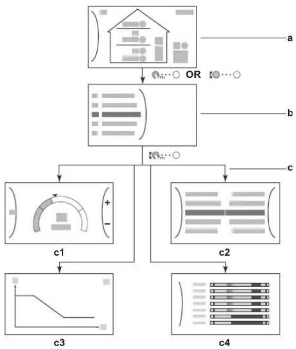
flowchart
graph TD
    A["House Icon"] --> B["OR"]
    B --> C["Process Step"]
    C --> D["c1: Data Flow +/-"]
    C --> E["c2: Data Flow +/-"]
    C --> F["c3: Data Flow -"]
    C --> G["c4: Data Flow -"]
a Home screen
b Main menu screen
c Lower level screens:
c1: Setpoint screen
c2: Detailed screen with values
c3: Screen with weather-dependent curve
c4: Screen with schedule
9.3.2 Home screen
Press the 🔊 button to go back to the home screen. You see an overview of the unit configuration and the room and setpoint temperatures. Only symbols applicable for your configuration are visible on the home screen.
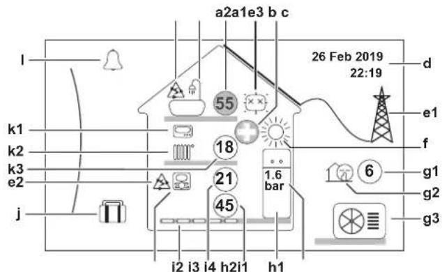
| Possible actions on this screen | |
| ○⋯○ | Go through the list of the main menu. |
| ○⋯○ | Go to the main menu screen. |
| ? | Enable/disable breadcrumbs. |
| Item Description | ||
| a Domestic hot water | ||
| a2 |  | Measured tank temperature(a) |
| b Disinfection / Powerful | ||
| [B65D] | Disinfection mode active | |
 | Powerful operation mode active | |
| c Emergency | ||
| d Current date and time | ||
| e Smart (W55A) | ||
| f Space c (X2DY) | ||
| °C | Cooling | |
| [T5YO] | Heating | |
| g Outdoor / quiet mode | ||
| h Indoor (X50Y) : hot water tank | ||
| i Main zone | ||
| i1 Installed room thermostat type: | ||
| (D423) | Unit operation is decided based on the ambient temperature of the dedicated Human Comfort Interface (BRC1HHDA used as room thermostat). | |
| (AAKC) | Unit operation is decided by the external room thermostat (wired or wireless). | |
| (HA65) No | room thermostat installed or set. Unit operation is decided based on the leaving water temperature regardless of the actual room temperature and/or heating demand of the room. | |
| i2 Installed heat emitter type: | ||
| (D436) | Underfloor heating | |
| [IMAGE] | Fancoil unit | |
| (HAAVT) | Radiator | |
| i3 [21] | Measured room temperature(a) | |
| i4 [7TBH] | Leaving water temperature setpoint(a) | |
| j Holiday mode | ||
| (2PTC) | Holiday mode active | |
| k Additional zone | ||
| k1 Installed room thermostat type: | ||
| (1477) | Unit operation is decided by the external room thermostat (wired or wireless). | |
| (RX2A) No | room thermostat installed or set. Unit operation is decided based on the leaving water temperature regardless of the actual room temperature and/or heating demand of the room. | |
| k2 Installed heat emitter type: | ||
| (TYXAB) | Underfloor heating | |
| [IMAGE] | Fancoil unit | |
| (TXTC) | Radiator | |
| k3 [00CC] | Leaving water temperature setpoint(a) | |
| I Malfunction | ||
| (SD66) | A malfunction occurred. | |
| (XCCT) | See "13.4.1 To display the help text in case of a malfunction" [▶ 224] for more information. | |
(e) If the corresponding operation (for example: space heating) is not active, the circle is greyed out.
9.3.3 Main menu screen
Starting from the home screen, press ( ) or turn ( ) the left dial to open the main menu screen. From the main menu, you can access the different setpoint screens and submenus.
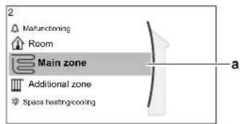
a Selected submenu
| Possible actions on this screen | |
| ○⋯○ | Go through the list. |
| ○⋯○ | Enter the submenu. |
| ? | Enable/disable breadcrumbs. |
| Submenu Description | ||
| [0] | orMalfunctioning | Restriction: Only displayed if a malfunction occurs.See "13.4.1 To display the help text in case of a malfunction" [▶ 224] for more information. |
| [1] | Room | Restriction: Only displayed if a dedicated Human Comfort Interface (BRC1HHDA used as room thermostat) is controlling the indoor unit.Set the room temperature. |
| [2] | Main zone | Shows the applicable symbol for your main zone emitter type.Set the leaving water temperature for the main zone. |
| [3] | Additional zone Restriction | Only displayed if there are two leaving water temperature zones. Shows the applicable symbol for your additional zone emitter type.Set the leaving water temperature for the additional zone (if present). |
| [4] | Space heating/ cooling | Shows the applicable symbol of your unit.Put the unit in heating mode or cooling mode.You cannot change the mode on heating only models. |
| [5] | Tank | Set the domestic hot water tank temperature. |
| [7] | User settings | Gives access to user settings such as holiday mode and quiet mode. |
| [8] | Information | Displays data and information about the indoor unit. |
[9] | Installer settings Commissioning Commissioning | Restriction: Only for the installer.Gives access to advanced settings.Restriction: Only for the installer.Perform tests and maintenance. |
 | [XAB7] User profile | Change the active user profile. |
| [AOAW] | [BSZ5] Operation | Turn heating/cooling functionality and domestic hot water preparation on or off. |
9.3.4 Menu screen
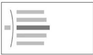
natural_image
Abstract geometric pattern with horizontal lines and a curved arrow (no text or symbols)Example:
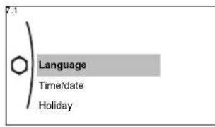
| Possible actions on this screen | |
| ○⋯○ | Go through the list. |
| ○⋯○ | Enter the submenu/setting. |
9.3.5 Setpoint screen
The setpoint screen is displayed for screens describing system components that need a setpoint value.
Examples
[1] Room temperature screen
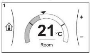
[2] Main zone screen
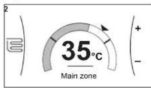
[3] Additional zone screen
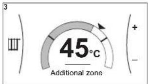
[5] Tank temperature screen
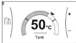
Explanation
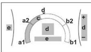
| Possible actions on this screen | |
| ○⋯○ | Go through the list of the submenu. |
| ○⋯○ | Go to the submenu. |
| ○···● | Adjust and automatically apply the desired temperature. |
| Item Description | ||
| Minimum temperature limit a1 Fixed by the unit | ||
| Maximum temperature limit b1 Fixed by the unit | ||
| Current temperature c Measured by the unit | ||
| Desired temperature d Turn the right dial to increase/decrease. | ||
| Submenu e Turn or press the left dial to go to | the submenu. | |
9.3.6 Detailed screen with values
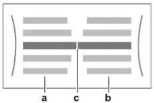
a Settings
b Values
c Selected setting and value
Example:
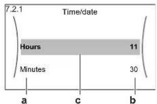
line
| Timeframe | Label | Value | | :--- | :--- | :--- | | Time/date | 7.2.1 | 11 | | Time/date | Minutes | 30 | | Time/date | a | - | | Time/date | c | - | | Time/date | b | - || Possible actions on this screen | |
| ○⋯○ | Go through the list of settings. |
| ○⋯○ | Change the value. |
| ○⋯○ | Go to the next setting. |
| ○⋯○ | Confirm changes and proceed. |
9.3.7 Schedule screen: Example
This example shows how to set a room temperature schedule in heating mode for the main zone.

INFORMATION
The procedures to program other schedules are similar.
To program the schedule: overview
Example: You want to program the following schedule:
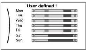
Prerequisite: The room temperature schedule is only available if room thermostat control is active. If leaving water temperature control is active, you can program the main zone schedule instead.
1 Go to the schedule.
2 (optional) Clear the content of the whole week schedule or the content of a selected day schedule.
3 Program the schedule for Monday.
4 Copy the schedule to the other weekdays.
5 Program the schedule for Saturday and copy it to Sunday.
6 Give the schedule a name.
To go to the schedule
| 1 Go to [1.1]: Room > Schedule. | ###...○ | |
| 2 Set scheduling to Yes. | ###...○ | |
| 3 Go to [1.2]: Room > Heating schedule. | ###...○ | |
To clear the content of the week schedule
1 Select the name of the current schedule.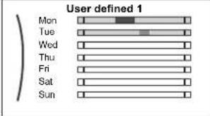 | ### | |
2 Select Delete. | ### | |
| 3 Select OK to confirm. | ### | |
To clear the content of a day schedule
1 Select the day of which you want to clear the content. For example Friday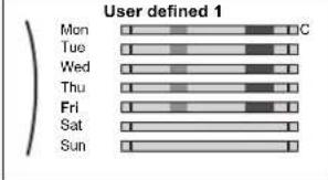 | ### |
2 Select Delete.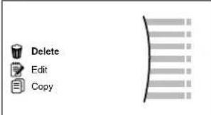 | ### |
| 3 Select OK to confirm. | ### |
To program the schedule for Monday
1 Select Monday.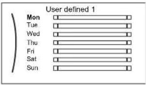 | ### | |
2 Select Edit.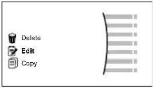 | ### | |
3 Use the left dial to select an entry and edit the entry with the right dial. You can program up to 6 actions each day. On the bar, a high temperature has a darker colour than a low temperature.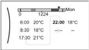 Note: To clear an action, set its time as the time of the previous action. Note: To clear an action, set its time as the time of the previous action. | ### | |
| 4 Confirm the changes.Result: The schedule for Monday is defined. The value of the last action is valid until the next programmed action. In this example, Monday is the first day you programmed. Thus, the last programmed action is valid up to the first action of next Monday. | ### | |
To copy the schedule to the other weekdays
1 Select Monday.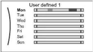 | ### | |
2 Select Copy.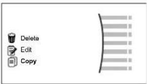 Result: Next to the copied day, "C" is displayed. Result: Next to the copied day, "C" is displayed. | ### | |
3 Select Tuesday.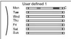 | ### | |
4 Select Paste.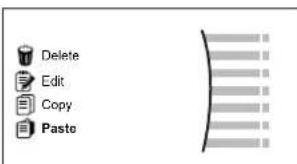 Result: Result: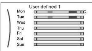 | ### | |
5 Repeat this action for all other weekdays.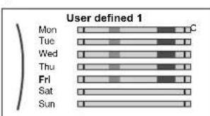 | — | |
To program the schedule for Saturday and copy it to Sunday
| 1 Select Saturday. | [IMAGE] | |
| 2 Select Edit. | [IMAGE] | |
3 Use the left dial to select an entry and edit the entry with the right dial.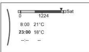 | [IMAGE] | |
| 4 Confirm the changes. | [IMAGE] | |
| 5 Select Saturday. | [IMAGE] | |
| 6 Select Copy. | [IMAGE] | |
| 7 Select Sunday. | [IMAGE] | |
8 Select Paste.Result: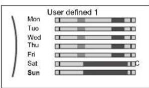 | [IMAGE] | |
To rename the schedule
1 Select the name of the current schedule.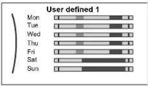 | ### |
2 Select Rename.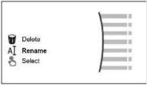 | ### |
| 3 (optional) To delete the current schedule name, browse through the character list until ← is displayed, then press to remove the previous character. Repeat for each character of the schedule name. | ○···· |
| 4 To name the current schedule, browse through the character list and confirm the selected character. The schedule name can contain up to 15 characters. | ○···· |
| 5 Confirm the new name. | ### |

INFORMATION
Not all schedules can be renamed.
9.4 Weather-dependent curve
9.4.1 What is a weather-dependent curve?
Weather-dependent operation
The unit operates 'weather dependent' if the desired leaving water or tank temperature is determined automatically by the outdoor temperature. It therefore is connected to a temperature sensor on the North wall of the building. If the outdoor temperature drops or rises, the unit compensates instantly. Thus, the unit does not have to wait for feedback by the thermostat to increase or decrease the temperature of the leaving water or tank. Because it reacts more quickly, it prevents high rises and drops of the indoor temperature and water temperature at tap points.
Advantage
Weather-dependent operation reduces energy consumption.
Weather-dependent curve
To be able to compensate for differences in temperature, the unit relies on its weather-dependent curve. This curve defines how much the temperature of the tank or leaving water must be at different outdoor temperatures. Because the slope of the curve depends on local circumstances such as climate and the insulation of the house, the curve can be adjusted by an installer or user.
Types of weather-dependent curve
There are 2 types of weather-dependent curves:
2-points curve
- Slope-offset curve
Which type of curve you use to make adjustments, depends on your personal preference. See "9.4.4 Using weather-dependent curves" [▶ 133].
Availability
The weather-dependent curve is available for:
- Main zone - Heating
- Main zone - Cooling
■ Additional zone - Heating
■ Additional zone - Cooling
Tank

INFORMATION
To operate weather dependent, correctly configure the setpoint of the main zone, additional zone or tank. See "9.4.4 Using weather-dependent curves" [▶ 133].
9.4.2 2-points curve
Define the weather-dependent curve with these two setpoints:
- Setpoint (X1, Y2)
- Setpoint (X2, Y1)
Example
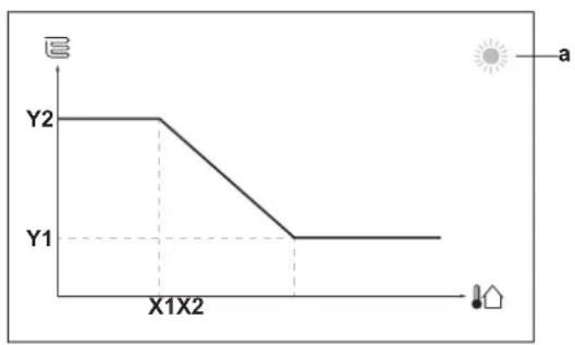
line
| Point | Value | |---|---| | Y1 | 0 | | Y2 | 0 | | X1X2 | 0 || Item Description | |
| a Selected weather dependent zone:Main zone or additional zone heatingMain zone or additional zone coolingDomestic hot water | |
| X1, X2 Examples of outdoor ambient temperature | |
| Y1, Y2 Examples of desired tank temperature or leaving water temperature.The icon corresponds to the heat emitter for that zone:Underfloor heatingFan coil unitRadiatorDomestic hot water tank |
| Possible actions on this screen | |
| ○⋯○ | Go through the temperatures. |
| ○⋯○ | Change the temperature. |
| ○⋯○ | Go to the next temperature. |
| ○⋯○ | Confirm changes and proceed. |
9.4.3 Slope-offset curve
Slope and offset
Define the weather-dependent curve by its slope and offset:
- Change the slope to differently increase or decrease the temperature of the leaving water for different ambient temperatures. For example, if leaving water temperature is in general fine but at low ambient temperatures too cold, raise the slope so that leaving water temperature is heated increasingly more at decreasingly lower ambient temperatures.
- Change the offset to equally increase or decrease the temperature of the leaving water for different ambient temperatures. For example, if leaving water temperature is always a bit too cold at different ambient temperatures, shift the offset up to equally increase the leaving water temperature for all ambient temperatures.
Examples
Weather-dependent curve when slope is selected:
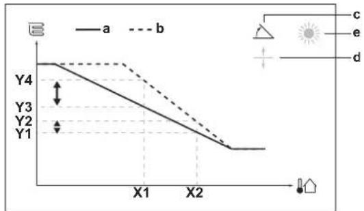
line
| YLevel | Curve a | Curve b | | ------ | ------- | ------- | | Y1 | 0 | 0 | | Y2 | 0 | 0 | | Y3 | 0 | 0 | | Y4 | 0 | 0 |Weather-dependent curve when offset is selected:
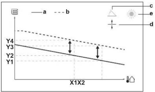
line
| X-axis | Y1 | Y2 | Y3 | Y4 | |---|---|---|---|---| | Left Line | - | - | - | - | | Right Line | - | - | - | - | | Top Label: (c) | - | - | - | - | | Bottom Label: (d) | - | - | - | - | | Arrows indicate direction of movement along X-axis from left to right. Legend: Solid line = a, Dashed line = b.| Item Description | |
| a WD curve before changes. | |
| b WD curve after changes (as example): ·When slope is changed, the new preferred temperature at X1 unequally higher than the preferred temperature at X2. ·When offset is changed, the new preferred temperature at X1 is equally higher as the preferred temperature at X2. | |
| c Slope | |
| d Offset | |
| e Selected weather dependent zone: ·Main zone or additional zone heating ·Main zone or additional zone cooling ·Domestic hot water | |
| X1, X2 Examples of outdoor ambient temperature | |
| Y1, Y2, Y3, Y4 | Examples of desired tank temperature or leaving water temperature. The icon corresponds to the heat emitter for that zone: ·Underfloor heating ·In coil unit ·Radiator ·Domestic hot water tank |
| Possible actions on this screen | |
| ○···○ | Select slope or offset. |
| ○···○ | Increase or decrease the slope/offset. |
| ○···○ | When slope is selected: set slope and go to offset.When offset is selected: set offset. |
| ○···○ | Confirm changes and return to the submenu. |
9.4.4 Using weather-dependent curves
Configure weather-dependent curves as following:
To define the setpoint mode
To use the weather-dependent curve, you need to define the correct setpoint mode:
| Go to setpoint mode ... Set the setpoint mode to ... | |
| Main zone – Heating | |
| [2.4] Main zone >Setpoint mode WD | heating, fixed cooling OR Weather dependent |
| Main zone – Cooling | |
| [2.4] Main zone >Setpoint mode Weather dependent | |
| Additional zone – Heating | |
| [3.4] Additional zone >Setpoint mode | WD heating, fixed cooling OR Weather dependent |
| Additional zone – Cooling | |
| [3.4] Additional zone >Setpoint mode | Weather dependent |
| Tank | |
| [5.B] Tank >Setpoint mode Weather dependent | |
To change the type of weather-dependent curve
To change the type for all zones and for the tank, go to [2.E] Main zone > WD curve type.
Viewing which type is selected is also possible via:
- [3.C] Additional zone >WD curve type
■ [5.E] Tank > WD curve type
To change the weather-dependent curve
| Zone Go to ... | |
| Main zone – Heating | [2.5] Main zone > Heating WD curve |
| Main zone – Cooling | [2.6] Main zone > Cooling WD curve |
| Additional zone – Heating | [3.5] Additional zone > Heating WD curve |
| Additional zone – Cooling | [3.6] Additional zone > Cooling WD curve |
| Tank [5.C] Tank > WD curve |

INFORMATION
Maximum and minimum setpoints
You cannot configure the curve with temperatures that are higher or lower than the set maximum and minimum setpoints for that zone or for the tank. When the maximum or minimum setpoint is reached, the curve flattens out.
To fine-tune the weather-dependent curve: slope-offset curve
The following table describes how to fine-tune the weather-dependent curve of a zone or tank:
| You feel ... Fine-tune with slope and offset: | |||
| At regular outdoor temperatures ... | At cold outdoor temperatures ... | Slope Offset | |
| OK Cold ↑ — | |||
| OK Hot ↓ — | |||
| Cold OK ↓ ↑ | |||
| Cold Cold — ↑ | |||
| Cold Hot ↓ ↑ | |||
| Hot OK ↑ ↓ | |||
| Hot Cold ↑ ↓ | |||
| Hot Hot — ↓ | |||
To fine-tune the weather-dependent curve: 2-points curve
The following table describes how to fine-tune the weather-dependent curve of a zone or tank:
| You feel ... Fine-tune with setpoints: | |||||
| At regular outdoor temperatures ... | At cold outdoor temperatures ... | Y2^(a) | Y1^(a) | X1^(a) | X2^(a) |
| OK Cold ↑ — | ↑ — | ||||
| OK Hot ↓ — | ↓ — | ||||
| Cold OK — ↑ — | ↑ | ||||
| Cold Cold ↑ ↑ | ↑ ↑ | ||||
| Cold Hot ↓ ↑ | ↓ ↑ | ||||
| Hot OK — ↓ — | ↓ | ||||
| Hot Cold ↑ ↓ | ↑ ↓ | ||||
| Hot Hot ↓ ↓ | ↓ ↓ | ||||
(a) See "9.4.2 2-points curve" [▶ 131].
9.5 Settings menu
You can set additional settings using the main menu screen and its submenus. The most important settings are presented here.
9.5.1 Malfunctioning
In case of a malfunction, ⚙ or ⚠ will appear on the home screen. To display the error code, open the menu screen and go to [0] Malfunctioning. Press ? for more information about the error.
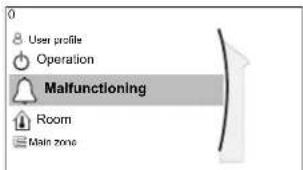
9.5.2 Room
Overview
The following items are listed in the submenu:
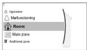
[1] Room
Setpoint screen
[1.1] Schedule
[1.2] Heating schedule
[1.3] Cooling schedule
[1.4] Antifrost
[1.5] Setpoint range
[1.6] Room sensor offset
[1.7] Room sensor offset
Setpoint screen
Control the room temperature of the main zone via setpoint screen [1] Room. See "9.3.5 Setpoint screen" [▶ 125].
Schedule
Indicate if the room temperature is controlled according to a schedule or not.
| # Code Description | |
| [1.1] N/A Schedule: | No: Room temperature is directly controlled by the user.Yes: Room temperature is controlled by a schedule and can be modified by the user. |
Heating schedule
Applicable for all models.
Define a heating schedule of the room temperature in [1.2] Heating schedule. See "9.3.7 Schedule screen: Example" [▶ 126].
Cooling schedule
Only applicable for reversible models.
Define a cooling schedule of the room temperature in [1.3] Cooling schedule. See "9.3.7 Schedule screen: Example" [▶ 126].
Antifrost
[1.4] Antifrost prevents the room from getting too cold. This setting is applicable when [2.9] Control=Room thermostat, but also offers functionality for leaving water temperature control and external room thermostat control. In case of the latter two, Antifrost can be activated by setting field setting [2-06]=1 .
Room frost protection, when enabled, is not guaranteed when there is no room thermostat that can activate the heat pump. This is the case when:
- [2.9] Control=External room thermostat and [C.2] Space heating/cooling=0ff, or if
- [2.9] Control=Leaving water.
In the above cases, Antifrost will heat the space heating water to a reduced setpoint when the outdoor temperature is lower than 6^ C.
| Main zone unit control method [2.9] | Description |
| Leaving water temperature control ([C-07]=0) | Room frost protection is NOT guaranteed. |
| External room thermostat control ([C-07]=1) | Allow for the external room thermostat to take care of room frost protection:• Set [C.2] Space heating/ cooling=On. |
| Room thermostat control ([C-07]=2) | Allow for the dedicated Human Comfort Interface (BRC1HHDA used as room thermostat) to take care of room frost protection:• Set antifrost [1.4.1] Activation=Yes.• Set the temperature of the antifrost function in [1.4.2] Room setpoint. |

INFORMATION
If a U4 error occurs, room frost protection is NOT guaranteed.

NOTICE
If the room Antifrost setting is active and a U4 error occurs, the unit will automatically start the Antifrost function via the backup heater. If the backup heater is not allowed, the room Antifrost setting MUST be disabled.

NOTICE
Room frost protection. Even if you turn OFF space heating/cooling operation ([C.2]: Operation > Space heating/cooling), room frost protection –if enabled– will remain active.
For more detailed information about room frost protection in relation to the applicable unit control method, see the sections below.
Leaving water temperature control ([C-07]=0)
Under leaving water temperature control, room frost protection is NOT guaranteed. However, if room antifrost [2-06] is activated, limited frost protection by the unit is possible:
| If... Then... | |
| Space heating/cooling =Off, andOutdoor ambient temperature drops below 6°C | The unit will supply leaving water to the heat emitters to heat up the room again, andthe temperature setpoint of the leaving water will be lowered. |
| Space heating/cooling=On, andOperation mode=Heating | The unit will supply leaving water to the heat emitters to heat up the room according to normal logic. |
| ▪ Space heating/cooling=On, and▪ Operation mode=Cooling | There is no room frost protection. |
External room thermostat control ([C-07]=1)
Under external room thermostat control, room frost protection is guaranteed by the external room thermostat, provided that:
[C.2] Space heating/cooling=On, and
[9.5.1] Emergency=Automatic or auto SH normal/DHW off.
However, if [1.4.1] Antifrost is activated, limited frost protection by the unit is possible.
In case of 1 leaving water temperature zone:
| If... Then... | |
| Space heating/cooling=Off, andOutdoor ambient temperature drops below 6°C | The unit will supply leaving water to the heat emitters to heat up the room again, andthe temperature setpoint of the leaving water will be lowered. |
| Space heating/cooling=On, andThe external room thermostat is "Thermo OFF", andOutdoor temperature drops below 6°C | The unit will supply leaving water to the heat emitters to heat up the room again, andthe temperature setpoint of the leaving water will be lowered. |
| Space heating/cooling=On, andThe external room thermostat is "Thermo ON" | Room frost protection is guaranteed by the normal logic. |
In case of 2 leaving water temperature zones:
| If... Then... | |
| Space heating/cooling=Off, andOutdoor ambient temperature drops below 6°C | The unit will supply leaving water to the heat emitters to heat up the room again, andthe temperature setpoint of the leaving water will be lowered. |
| Space heating/cooling=On, andOperation mode=Heating, andThe external room thermostat is "Thermo OFF", andOutdoor temperature drops below 6°C | The unit will supply leaving water to the heat emitters to heat up the room again, andthe temperature setpoint of the leaving water will be lowered. |
| Space heating/cooling=On, andOperation mode=Cooling | There is no room frost protection. |
Room thermostat control ([C-07]=2)
During room thermostat control, room frost protection [2-06] is guaranteed when activated. If so, and the room temperature drops below the room antifrost temperature [2-05] , the unit will supply leaving water to the heat emitters to heat up the room again.
| # Code Description | |
| [1.4.1] [2-06] Activation: | 0 No: Antifrost functionality is OFF.1 Yes: Antifrost functionality is on. |
| [1.4.2] [2-05] Room setpoint: | 4°C~16°C |
![DAIKIN ETVX16S18DA9W - External room thermostat control ([C-07]=1) - 1](/content/2026/05/911660/images/288156a5b6aae00f78440eb506b7f1d6aed702f98370bcfa9b4ad5fc80698224.jpg)
INFORMATION
When the dedicated Human Comfort Interface (BRC1HHDA used as room thermostat) is disconnected (because of incorrect wiring or damage of the cable), then room frost protection is NOT guaranteed.

NOTICE
If Emergency is set to Manual ([9.5.1]=0), and the unit is triggered to start emergency operation, the unit will stop and needs to be recovered manually via the user interface. To recover operation manually, go to the Malfunctioning main menu screen, and confirm emergency operation before starting.
Room frost protection is active even if the user does not confirm emergency operation.
Setpoint range
Only applicable in room thermostat control.
To save energy by preventing overheating or undercooling the room, you can limit the range of the room temperature for heating and/or cooling.

NOTICE
When adjusting the room temperature ranges, all desired room temperatures are also adjusted to guarantee they are between the limits.
| # Code Description | |
| [1.5.1] [3-07] Heating minimum | |
| [1.5.2] [3-06] Heating maximum | |
| [1.5.3] [3-09] Cooling minimum | |
| [1.5.4] [3-08] Cooling maximum | |
Room sensor offset
Only applicable in room thermostat control.
To calibrate the (external) room temperature sensor, give an offset to the value of the room thermistor as measured by the Human Comfort Interface (BRC1HHDA used as room thermostat) or by the external room sensor. The setting can be used to compensate for situations where the Human Comfort Interface or the external room sensor cannot be installed at the ideal location.
See "5.7 Setting up an external temperature sensor" [▶ 53].
| # Code Description | |
| [1.6] [2-0A] Room sensor offset (Human Comfort Interface (BRC1HHDA used as room thermostat)): Offset on the actual room temperature measured by the Human Comfort Interface.▪ -5°C~5°C, step 0.5°C | |
| [1.7] [2-09] Room sensor offset (external room sensor option): Only applicable if the external room sensor option is installed and configured.▪ -5°C~5°C, step 0.5°C | |
9.5.3 Main zone
Overview
The following items are listed in the submenu:
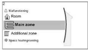
[2] Main zone
Setpoint screen
[2.1] Schedule
[2.2] Heating schedule
[2.3] Cooling schedule
[2.4] Setpoint mode
[2.5] Heating WD curve
[2.6] Cooling WD curve
[2.7] Emitter type
[2.8] Setpoint range
[2.9] Control
[2.A] Thermostat type
[2.B] Delta T
[2.C] Modulation
[2.D] Shut off valve
[2.E] WD curve type
Setpoint screen
Control the leaving water temperature for the main zone via setpoint screen [2] Main zone.
See "9.3.5 Setpoint screen" [▶ 125].
Schedule
Indicate if the temperature of the leaving water is defined according to a schedule or not.
Influence of the LWT setpoint mode [2.4] is as follows:
- In Fixed LWT setpoint mode, the scheduled actions consist of desired leaving water temperatures, either preset or custom.
- In Weather dependent LWT setpoint mode, the scheduled actions consist of desired shift actions, either preset or custom.
| # Code Description | |
| [2.1] N/A Schedule: | 0: No1: Yes |
Heating schedule
Define a heating temperature schedule for the main zone via [2.2] Heating schedule.
See "9.3.7 Schedule screen: Example" [▶ 126].
Cooling schedule
Define a cooling temperature schedule for the main zone via [2.3] Cooling schedule.
See "9.3.7 Schedule screen: Example" [▶ 126].
Setpoint mode
Define the setpoint mode:
- Fixed: the desired leaving water temperature does not depend on the outdoor ambient temperature.
- In WD heating, fixed cooling mode, the desired leaving water temperature:
- depends on the outdoor ambient temperature for heating
- does NOT depend on the outdoor ambient temperature for cooling
- In Weather dependent mode, the desired leaving water temperature depends on the outdoor ambient temperature.
| # Code Description | |
| [2.4] N/A Setpoint mode: | FixedWD heating, fixed coolingWeather dependent |
When weather dependent operation is active, low outdoor temperatures will result in warmer water and vice versa. During weather dependent operation, the user can shift the water temperature up or down by a maximum of 10^ C.
WD curve type
The weather dependent curve can be defined using the 2-points method or the Slope-Offset method.
See "9.4.2 2-points curve" [▶ 131] and "9.4.3 Slope-offset curve" [▶ 132].
| # Code Description | |
| [2.E] N/A • 2-points | • Slope-Offset |
Heating WD curve
Set weather-dependent heating for the main zone (if [2.4]=1 or 2):
| # Code Description | |
| [2.5] [1-00] | Set weather-dependent heating in [2.5] Heating WD curve: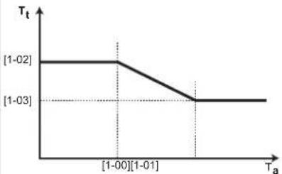 T_1 Target leaving water temperature (main zone) T_a Outdoor temperatureSet weather-dependent heating in [9.I]Overview field settings:[1-00]: Low outdoor ambient temperature. - 40°C~+5°C[1-01]: High outdoor ambient temperature. 10°C~25°C[1-02]: Desired leaving water temperature when the outdoor temperature equals or drops below the low ambient temperature.[9-01]°C~[9-00]°CNote: This value should be higher than [1-03] as for low outdoor temperatures warmer water is required.[1-03]: Desired leaving water temperature when the outdoor temperature equals or rises above the high ambient temperature.[9-01]°C~min(45, [9-00])°CNote: This value should be lower than [1-02] as for high outdoor temperatures less warm water is required. T_1 Target leaving water temperature (main zone) T_a Outdoor temperatureSet weather-dependent heating in [9.I]Overview field settings:[1-00]: Low outdoor ambient temperature. - 40°C~+5°C[1-01]: High outdoor ambient temperature. 10°C~25°C[1-02]: Desired leaving water temperature when the outdoor temperature equals or drops below the low ambient temperature.[9-01]°C~[9-00]°CNote: This value should be higher than [1-03] as for low outdoor temperatures warmer water is required.[1-03]: Desired leaving water temperature when the outdoor temperature equals or rises above the high ambient temperature.[9-01]°C~min(45, [9-00])°CNote: This value should be lower than [1-02] as for high outdoor temperatures less warm water is required. |
Cooling WD curve
Set weather-dependent cooling for the main zone (if [2.4]=2):
| # Code Description | |
| [2.6] [1-06] | Set weather-dependent cooling in [2.6] Cooling WD curve: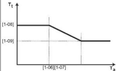 T_t Target leaving water temperature (main zone) T_a Outdoor temperatureSet weather-dependent heating in [9.1]Overview field settings:[1-06]: Low outdoor ambient temperature. 10^ 25^ [1-07]: High outdoor ambient temperature. 25^ 43^ [1-08]: Desired leaving water temperature when the outdoor temperature equals or drops below the low ambient temperature. [9-03]^ [9-02]^ Note: This value should be higher than [1-09] as for low outdoor temperatures less cold water is required.[1-09]: Desired leaving water temperature when the outdoor temperature equals or rises above the high ambient temperature. [9-03]^ [9-02]^ Note: This value should be lower than [1-08] as for high outdoor temperatures colder water is required. T_t Target leaving water temperature (main zone) T_a Outdoor temperatureSet weather-dependent heating in [9.1]Overview field settings:[1-06]: Low outdoor ambient temperature. 10^ 25^ [1-07]: High outdoor ambient temperature. 25^ 43^ [1-08]: Desired leaving water temperature when the outdoor temperature equals or drops below the low ambient temperature. [9-03]^ [9-02]^ Note: This value should be higher than [1-09] as for low outdoor temperatures less cold water is required.[1-09]: Desired leaving water temperature when the outdoor temperature equals or rises above the high ambient temperature. [9-03]^ [9-02]^ Note: This value should be lower than [1-08] as for high outdoor temperatures colder water is required. |
Emitter type
Heating up or cooling down the main zone can take longer. This depends on:
• The water volume of the system
- The heater emitter type of the main zone
The setting Emitter type can compensate for a slow or a quick heating/cooling system during the heat up/cool down cycle. In room thermostat control, Emitter type influences the maximum modulation of the desired leaving water temperature, and the possibility for usage of the automatic cooling/heating changeover based on the indoor ambient temperature.
It is important to set Emitter type correctly and in accordance with your system layout. The target delta T for the main zone depends on it.
| # Code Description | |
| [2.7] [2-0C] Emitter type: | 0: Underfloor heating1: Fancoil unit2: Radiator |
The setting Emitter type influences the space heating setpoint range and the target delta T in heating as follows:
| Emitter type Main zone | Space heating setpoint range [9-01]~[9-00] | Target delta T in heating [1-0B] |
| 0: Underfloor heating | Maximum 55°C Variable (see [2.B]) | |
| 1: Fancoil unit Maximum | um 55°C Variable (see [2.B]) | |
| 2: Radiator Maximum | 70°C Fixed 10°C |

NOTICE
The maximum setpoint in space heating depends on the emitter type as can be seen in above table. If there are 2 water temperature zones, then the maximum setpoint is the maximum of the 2 zones.

CAUTION
NOT configuring the system in the following way can cause damage to the heat emitters. If there are 2 zones, it is important that in heating:
■ the zone with the lowest water temperature is configured as the main zone, and
- the zone with the highest water temperature is configured as the additional zone.

CAUTION
If there are 2 zones and the emitter types are wrongly configured, water of high temperature can be sent towards a low temperature emitter (underfloor heating). To avoid this:
- Install an aquastat/thermostatic valve to avoid too high temperatures towards a low temperature emitter.
- Make sure you set the emitter types for the main zone [2.7] and for the additional zone [3.7] correctly in accordance with the connected emitter.

INFORMATION
Depending on the target delta T, the average emitter temperature will vary. To counteract the effect on the average emitter temperature due to a higher delta T target, the leaving water setpoint (fixed or weather dependent) can be adjusted.
Setpoint range
To prevent a wrong (i.e. too hot or too cold) leaving water temperature for the main leaving water temperature zone, limit its temperature range.

NOTICE
In case of a floor heating application it is important to limit the:
- maximum leaving water temperature at heating operation according to the specifications of the floor heating installation.
- the minimum leaving water temperature at cooling operation to 18\~20°C to prevent condensation on the floor.

NOTICE
- When adjusting the leaving water temperature ranges, all desired leaving water temperatures are also adjusted to guarantee they are between the limits.
- Always balance between the desired leaving water temperature with the desired room temperature and/or the capacity (according to the design and selection of the heat emitters). The desired leaving water temperature is the result of several settings (preset values, shift values, weather-dependent curves, modulation). As a result, too high or too low leaving water temperatures could occur which lead to overtemperatures or capacity shortage. By limiting the leaving water temperature range to adequate values (depending on the heat emitter), such situations can be avoided.
Example: In heating mode, leaving water temperatures must be sufficiently higher than the room temperatures. To avoid that the room cannot heat up as desired, set the minimum leaving water temperature to 28^ C.
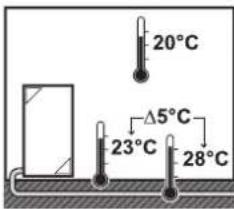
| # Code Description | ||
| Leaving water temperature range for the main leaving water temperature zone (= the leaving water temperature zone with the lowest leaving water temperature in heating operation and the highest leaving water temperature in cooling operation) | ||
| [2.8.1] [9-01] Heating minimum: · 15°C~37°C | ||
| [2.8.2] [9-00] Heating maximum: · [2-0C]=2 (emitter type main zone = radiator) 37°C~70°C · Otherwise: 37°C~55°C | ||
| [2.8.3] [9-02] Cooling minimum: · 5°C~18°C | ||
| [2.8.4] [9-03] Cooling maximum: · 18°C~22°C | ||
Control
Define how the operation of the unit is controlled.
| Control In this control... | |
| Leaving water Unit operation is decided based on the leaving water temperature regardless the actual room temperature and/or heating or cooling demand of the room. | |
| External room thermostat | Unit operation is decided by the external thermostat or equivalent (e.g. heat pump convector). |
| Room thermostat Unit operation is decided based on the ambient temperature of the dedicated Human Comfort Interface (BRC1HHDA used as room thermostat). | |
| # Code Description | |
| [2.9] [C-07] • 0: | Leaving water• 1: External room thermostat• 2: Room thermostat |
Thermostat type
Only applicable in external room thermostat control.

NOTICE
If an external room thermostat is used, the external room thermostat will control the room frost protection. However, the room frost protection is only possible if [C.2] Space heating/cooling=On.
| # Code Description | |
| [2.A] [C-05] External room thermostat type for the main zone:1: 1 contact: The used external room thermostat can only send a thermo ON/OFF condition. There is no separation between heating or cooling demand. The room thermostat is connected to only 1 digital input (X2M/35).Select this value in case of a connection to the heat pump convector (FWXV).2: 2 contacts: The used external room thermostat can send a separate heating/cooling thermo ON/OFF condition. The room thermostat is connected to 2 digital inputs (X2M/35 and X2M/34).Select this value in case of a connection to multi-zoning wired controls (see "4.3.3 Possible options for the indoor unit" [▶ 24]) or wireless room thermostat (EKRTR1). | |
Leaving water temperature: Delta T
In heating for the main zone, the target delta T (temperature difference) depends on the selected emitter type for the main zone.
Delta T is the absolute value of the temperature difference between the leaving water and entering water.
The unit is designed to support underfloor loops operation. The recommended leaving water temperature for underfloor loops is 35^ C. In such case, the unit will realize a temperature difference of 5^ C, which means that the entering water temperature is around 30^ C.
Depending on the installed type of heat emitters (radiators, heat pump convector, underfloor loops) or situation, you can change the difference between entering and leaving water temperature.
Note: The pump will regulate its flow to keep the delta T. In some special cases, the measured delta T can differ from the set value.

INFORMATION
When only the backup heater is active in heating, delta T will be controlled according to the fixed capacity of the backup heater. It is possible that this delta T is different from the selected target delta T.

INFORMATION
In heating, the target delta T will only be achieved after some operation time, when the setpoint is being reached, because of the big difference between leaving water temperature setpoint and inlet temperature at startup.

INFORMATION
If the main zone or the additional zone has a heating demand, and this zone is equipped with radiators, then the target delta T that the unit will use in heating operation will be 10^ C fixed.
If the zones are not equipped with radiators, then in heating the unit will give priority to the target delta T for the additional zone, if there is a heating demand in the additional zone.
In cooling the unit will give priority to the target delta T for the additional zone, if there is a cooling demand in the additional zone.
| # Code Description | |
| [2.B.1] [1-0B] Delta T heating | A minimum temperature difference is required for proper operation of heat emitters in heating mode.If [2-0C]=2, this is fixed to 10°CElse: 3°C~10°C |
| [2.B.2] [1-0D] Delta T cooling | A minimum temperature difference is required for proper operation of heat emitters in cooling mode.3°C~10°C |
Leaving water temperature: Modulation
Only applicable in case of room thermostat control.
When using the room thermostat functionality, the customer needs to set the desired room temperature. The unit will supply hot water to the heat emitters and the room will be heated.
Additionally, also the desired leaving water temperature must be configured: if Modulation is enabled, the unit automatically calculates the desired leaving water temperature. These calculations are based on:
■ the preset temperatures, or
- the desired weather-dependent temperatures (if weather-dependent is enabled)
Moreover, with Modulation enabled, the desired leaving water temperature is lowered or raised in function of the desired room temperature and the difference between the actual and the desired room temperature. This results in: - stable room temperatures, exactly matching the desired temperature (higher comfort level)
- less on/off cycles (lower noise level, higher comfort and higher efficiency)
- water temperatures as low as possible to match the desired temperature (higher efficiency)
If Modulation is disabled, set the desired leaving water temperature via [2] Main zone.
| # Code Description | |
| [2.C.1] [8-05] Modulation: | 0 No (disabled)1 Yes (enabled)Note:The desired leaving water temperature can only be read out on the user interface. |
| [2.C.2] [8-06] Max modulation: | 0°C~10°CThis is the temperature value by which the desired leaving water temperature is increased or decreased. |

INFORMATION
When leaving water temperature modulation is enabled, the weather-dependent curve needs to be set to a higher position than [8-06] plus the minimum leaving water temperature setpoint required to reach a stable condition on the comfort setpoint for the room. To increase efficiency, modulation can lower the leaving water setpoint. By setting the weather-dependent curve to a higher position, it cannot drop below the minimum setpoint. See the illustration below.
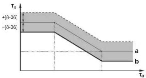
area
| Ta Range | Tt Range | |----------|----------| | [8-06] | +[8-06] | | [8-06] | -[8-06] | | [8-06] | a | | [8-06] | b |a Weather-dependent curve
b Minimum leaving water temperature setpoint required to reach a stable condition on the comfort setpoint for the room.
Shut off valve
The following is only applicable in case of 2 leaving water temperature zones. In case of 1 leaving water temperature zone, connect the shut-off valve to the heating/cooling output.
The shut off valve for the main leaving water temperature zone can close under these circumstances:

INFORMATION
During defrost operation, the shut-off valve is ALWAYS opened.
During thermo: If [F-OB] is enabled, the shut off valve closes when there is no heating demand from the main zone. Enable this setting to:
- avoid leaving water supply to the heat emitters in the main LWT zone (through the mixing valve station) when there is request from the additional LWT zone.
- activate the ON/OFF pump of the mixing valve station ONLY when there is demand.
| # Code | Description | |
| [2.D.1] [F-0B] The shut off valve: | 0 No: is NOT influenced by heating or cooling demand.1 Yes: closes when there is NO heating or cooling demand. | |

INFORMATION
The setting [F-0B] is only valid when there is a thermostat or external room thermostat request setting (NOT in case of leaving water temperature setting).
During cooling: If [F-OB] is enabled, the shut off valve closes when the unit is running in cooling operation mode. Enable this setting to avoid cold leaving water through the heat emitter and the forming of condensation (e.g. under floor heating loops or radiators).
| # Code | Description | |
| [2.D.2] [F-0C] The shut off valve: | 0 No: is NOT influenced by changing the space operation mode to cooling.1 Yes: closes when the space operation mode is cooling. | |
9.5.4 Additional zone
Overview
The following items are listed in the submenu:
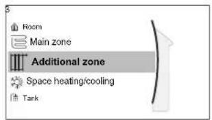
[3] Additional zone
Setpoint screen
[3.1] Schedule
[3.2] Heating schedule
[3.3] Cooling schedule
[3.4] Setpoint mode
[3.5] Heating WD curve
[3.6] Cooling WD curve
[3.7] Emitter type
[3.8] Setpoint range
[3.9] Control
[3.A] Thermostat type
[3.B] Delta T
[3.C] WD curve type
Setpoint screen
Control the leaving water temperature for the additional zone via setpoint screen [3] Additional zone.
See "9.3.5 Setpoint screen" [▶ 125].
Schedule
Indicates if the desired leaving water temperature is according to a schedule.
See "9.5.3 Main zone" [▶ 140].
| # Code Description | |
| [3.1] N/A Schedule: | NoYes |
Heating schedule
Define a heating temperature schedule for the additional zone via [3.2] Heating schedule.
See "9.3.7 Schedule screen: Example" [▶ 126].
Cooling schedule
Define a cooling temperature schedule for the additional zone via [3.3] Cooling schedule.
See "9.3.7 Schedule screen: Example" [▶ 126].
Setpoint mode
The setpoint mode of the additional zone can be independently set from the setpoint mode of the main zone.
See "Setpoint mode" [▶ 141].
| # Code Description | |
| [3.4] N/A Setpoint mode: | FixedWD heating, fixed coolingWeather dependent |
WD curve type
The weather dependent curve can be defined using the 2-points method or the Slope-Offset method.
Also see "9.4.2 2-points curve" [▶ 131] and "9.4.3 Slope-offset curve" [▶ 132].
The curve type in the menu of the additional zone is read only. It corresponds to the curve type that is in use for the main zone. Thus, changing the curve type for the additional zone must be done in the menu of the main zone: [2.E] WD curve type.
Also see "9.5.3 Main zone" [▶ 140].
| # Code Description | |
| [2.E] N/A • 2-points | • Slope-Offset |
Heating WD curve
Set weather-dependent heating for the additional zone (if [3.4]=1 or 2):
| # Code Description | |
| [3.5] [0-00] | Set weather-dependent heating: T_t : Target leaving water temperature (additional zone) T_a : Outdoor temperature [0-03] : Low outdoor ambient temperature. -40^ +5^ [0-02] : High outdoor ambient temperature. 10^ 25^ [0-01] : Desired leaving water temperature when the outdoor temperature equals or drops below the low ambient temperature. [9-05]^ [9-06]^ Note: This value should be higher than [0-00] as for low outdoor temperatures warmer water is required. [0-00] : Desired leaving water temperature when the outdoor temperature equals or rises above the high ambient temperature. [9-05]^(45, [9-06])^ Note: This value should be lower than [0-01] as for high outdoor temperatures less warm water is required. |
Cooling WD curve
Set weather-dependent cooling for the additional zone (if [3.4]=2):
| # Code Description | |
| [3.6] [0-04] | Set weather-dependent cooling: T_t Target leaving water temperature (additional zone) T_a : Outdoor temperature[0-07]: Low outdoor ambient temperature. 10^ 25^ [0-06]: High outdoor ambient temperature. 25^ 43^ [0-05]: Desired leaving water temperature when the outdoor temperature equals or drops below the low ambient temperature. [9-07]^ [9-08]^ Note: This value should be higher than [0-04] as for low outdoor temperatures less cold water is required.[0-04]: Desired leaving water temperature when the outdoor temperature equals or rises above the high ambient temperature. [9-07]^ [9-08]^ Note: This value should be lower than [0-05] as for high outdoor temperatures colder water is required. |
Emitter type
For more information about Emitter type, see "9.5.3 Main zone" [▶ 140].
| # Code Description | ||
| [3.7] [2-0D] | Emitter | type:0: Underfloor heating1: Fancoil unit2: Radiator |
The setting of the emitter type has an influence on the space heating setpoint range and the target delta T in heating as follows:
| Emitter type Additional zone | Space heating setpoint range [9-05]~[9-06] | Target delta T in heating [1-0C] |
| 0: Underfloor heating | Maximum 55°C | Variable (see [3.B.1]) |
| 1: Fancoil unit | Maximum 55°C | Variable (see [3.B.1]) |
| 2: Radiator | Maximum 70°C | Fixed 10°C |
Setpoint range
For more information about Setpoint range, see "9.5.3 Main zone" [▶ 140].
| # Code Description | ||
| Leaving water temperature range for the main leaving water temperature zone (= the leaving water temperature zone with the lowest leaving water temperature in heating operation and the highest leaving water temperature in cooling operation) | ||
| [2.8.1] [9-01] Heating minimum: · 15°C~37°C | ||
| [2.8.2] [9-00] Heating maximum: · [2-0C]=2 (emitter type main zone = radiator) 37°C~70°C · Otherwise: 37°C~55°C | ||
| [2.8.3] [9-02] Cooling minimum: · 5°C~18°C | ||
| [2.8.4] [9-03] Cooling maximum: · 18°C~22°C | ||
Control
The control type for the additional zone is read only. It is determined by the control type of the main zone.
See "9.5.3 Main zone" [▶ 140].
| # Code Description | |
| [3.9] N/A Control: | Leaving water if the control type of the main zone is Leaving water.External room thermostat if the control type of the main zone is:- External room thermostat,or- Room thermostat. |
Thermostat type
Only applicable in external room thermostat control.
Also see "9.5.3 Main zone" [▶ 140].
| # Code Description | ||
| [3.A] | [C-06] External | room thermostat type for the additional zone:1: 1 contact. Connected to only 1 digital input (X2M/35a)2: 2 contacts. Connected to 2 digital inputs (X2M/34a and X2M/35a) |
Leaving water temperature: Delta T
For more information, see "9.5.3 Main zone" [▶ 140].
| # Code Description | |
| [3.B.1] [1-0C] Delta T heating | A minimum temperature difference is required for the good operation of heat emitters in heating mode.If [2-0D] = 2, this is fixed to 10^ Else: 3^ 10^ |
| [3.B.2] [1-0E] Delta T cooling | A minimum temperature difference is required for the good operation of heat emitters in cooling mode. 3^ 10^ |
9.5.5 Space heating/cooling
Overview
The following items are listed in the submenu:
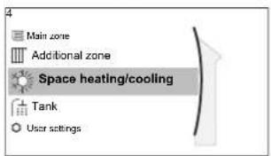
[4] Space heating/cooling
[4.1] Operation mode
[4.2] Operation mode schedule
[4.3] Operation range
[4.4] Number of zones
[4.5] Pump operation mode
[4.6] Unit type
[4.7] Pump limitation
[4.8] Pump limitation
[4.9] Pump outside range
[4.A] Increase around 0^ C
[4.B] Overshoot
[4.C] Antifrost
About space operation modes
Your unit can be a heating or a heating/cooling model:
- If your unit is a heating model, it can heat up a space.
- If your unit is a heating/cooling model, it can both heat up and cool down a space. You have to tell the system which operation mode to use.
To determine if a heating/cooling heat pump model is installed
| 1 Go to [4]: Space heating/cooling. | ### | |
| 2 Check if [4.1] Operation mode is listed and editable. If so, a heating/cooling heat pump model is installed. | ### | |
To tell the system which space operation to use, you can:
| You can... Location | |
| Check which space operation mode is currently used. Home screen | |
| Set the space operation mode permanently. Main menu | |
| Restrict automatic changeover according to a monthly schedule. | |
To check which space operation mode is currently used
The space operation mode is displayed on the home screen:
- When the unit is in heating mode, the icon is shown.
- When the unit is in cooling mode, the icon is shown.
The status indicator shows if the unit is currently in operation:
- When the unit is not in operation, the status indicator will show a blue pulsation with an interval of approximately 5 seconds.
- While the unit is in operation, the status indicator will light up blue constantly.
To set the space operation mode
| 1 | Go to [4.1]: Space heating/cooling >Operation mode | ### |
| 2 | Select one of the following options:Heating: Only heating modeCooling: Only cooling modeAutomatic: The operation mode changes automatically based on the outdoor temperature. Restricted according to the operation mode schedule. | ### |
Automatic heating/cooling changeover is only applicable for:
■ Reversible models
■ Heating only models + conversion kit (EKHVCONV2)
When Automatic is selected, the unit switches its operation mode, based on the Operation mode schedule [4.2] . In this schedule, the end user indicates which operation is allowed for each month.
To restrict automatic changeover according to a schedule
Conditions: You set the space operation mode to Automatic.
| 1 | Go to [4.2]: Space heating/cooling > Operation mode schedule. | |
| 2 | Select a month. | |
| 3 | For each month, select an option:Reversible: Not restrictedHeating only: RestrictedCooling only: Restricted | |
| 4 | Confirm the changes. |
Example: Changeover restrictions
| When Restriction | |
| During cold season.Example: October, November, December, January, February and March. | Heating only |
| During warm season.Example: June, July and August. | Cooling only |
| In-between.Example: April, May and September. | Reversible |
The unit determines its operation mode by the outdoor temperature if:
- Operation mode=Automatic, and
- Operation mode schedule=Reversible.
The unit determines its operation mode in such a way that it will always stay within the following operation ranges:
- Space heating off temperature
- Space cooling off temperature
The outdoor temperature is time-averaged. If the outdoor temperature drops, the operation mode will switch to heating and vice versa.
If the outdoor temperature is between the Space heating off temperature and the Space cooling off temperature, the operation mode remains unchanged.
Operation range
Depending on the average outdoor temperature, the operation of the unit in space heating or space cooling is prohibited.
| # Code Description | |
| [4.3.1] [4-02] Space heating | off temperature: When the averaged outdoor temperature rises above this value, space heating is turned off. ^(a) · 14°C~35°C |
| [4.3.2] [F-01] Space cooling | off temperature: When the averaged outdoor temperature drops below this value, space cooling is turned off. ^(a) · 10°C~35°C |
(c) This setting is also used in automatic heating/cooling changeover.
Exception: If the system is configured in room thermostat control with one leaving water temperature zone and quick heat emitters, the operation mode will change based on the measured indoor temperature. Besides the desired heating/cooling room temperature, the installer sets a hysteresis value (e.g. when in heating, this value is related to the desired cooling temperature) and an offset value (e.g. when in heating, this value is related to the desired heating temperature).
Example: A unit is configured as following:
- Desired room temperature in heating mode: 22°C
- Desired room temperature in cooling mode: 24°C
- Hysteresis value: 1°C
- Offset: 4^ C
Changeover from heating to cooling will occur when the room temperature rises above the maximum of the desired cooling temperature added by the hysteresis value (thus 24+1=25^ ) and the desired heating temperature added by the offset value (thus 22+4=26^ ).
Oppositely, changeover from cooling to heating will occur when the room temperature drops below the minimum of the desired heating temperature subtracted by the hysteresis value (thus 22–1=21°C) and the desired cooling temperature subtracted by the offset value (thus 24–4=20°C)
Guard timer to prevent too frequent changing from heating to cooling and vice versa.
| # Code Description | |
| Changeover settings related to the indoor temperature.Only applicable when Automatic is selected and the system is configured in room thermostat control with 1 leaving water temperature zone and quick heat emitters. | |
| N/A [4-0B] Hysteresis: ensures that changeover is only done when necessary.The space operation only changes from heating to cooling when the room temperature rises above the desired cooling temperature added by the hysteresis value.- Range: 1°C~10°C | |
| N/A [4-0D] Offset: ensures that the active desired room temperature is always reached.In heating mode, the space operation only changes when the room temperature rises above the desired heating temperature added by the offset value.- Range: 1°C~10°C | |
Number of zones
The system can supply leaving water to up to 2 water temperature zones. During configuration, the number of water zones must be set.

INFORMATION
Mixing station. If your system layout contains 2 LWT zones, you need to install a mixing station in front of the main LWT zone.
| # Code Description | ||
| [4.4] [7-02] • 0: | Single zone | Only one leaving water temperature zone: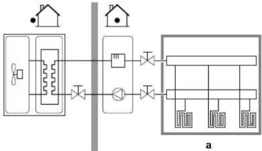 a Main LWT zone a Main LWT zone |
| # Code Description | |
| [4.4] [7-02] • 1: Dual zone | Two leaving water temperature zones. The main leaving water temperature zone consists of the higher load heat emitters and a mixing station to achieve the desired leaving water temperature. In heating: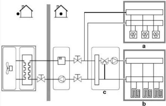 a Additional LWT zone: Highest temperatureb Main LWT zone: Lowest temperaturec Mixing station a Additional LWT zone: Highest temperatureb Main LWT zone: Lowest temperaturec Mixing station |

CAUTION
NOT configuring the system in the following way can cause damage to the heat emitters. If there are 2 zones, it is important that in heating:
- the zone with the lowest water temperature is configured as the main zone, and
- the zone with the highest water temperature is configured as the additional zone.

CAUTION
If there are 2 zones and the emitter types are wrongly configured, water of high temperature can be sent towards a low temperature emitter (underfloor heating). To avoid this:
- Install an aquastat/thermostatic valve to avoid too high temperatures towards a low temperature emitter.
■ Make sure you set the emitter types for the main zone [2.7] and for the additional zone [3.7] correctly in accordance with the connected emitter.
Pump operation mode
When the space heating/cooling operation is OFF, the pump is always OFF. When space heating/cooling operation is ON, you have the choice between these operation modes:
| # Code Description | |
| [4.5] [F-0D] Pump operation | mode:▪ 0 Continuous: Continuous pump operation, regardless of thermo ON or OFF condition.Remark: Continuous pump operation requires more energy than sample or request pump operation.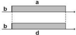 a Space heating/cooling controlb Offc Ond Pump operation a Space heating/cooling controlb Offc Ond Pump operation |
[4.5] [F-0D]▪ 1 Sample: The pump is ON when there is heating or cooling demand as the leaving water temperature has not yet reached the desired temperature yet. When thermo OFF condition occurs, the pump runs every 3 minutes to check the water temperature and demand heating or cooling if necessary.Remark:Sample is ONLY available in leaving water temperature control.a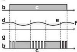 a Space heating/cooling controlb Offc Ond LWT temperaturee Actualf Desiredg Pump operation a Space heating/cooling controlb Offc Ond LWT temperaturee Actualf Desiredg Pump operation | |
[4.5] [F-0D]▪ 2 Request: Pump operation based on request.Example: Using a room thermostat and thermostat creates thermo ON/OFF condition.Remark: NOT available in leaving water temperature control.a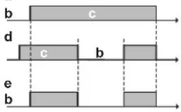 a Space heating/cooling controlb Offc Ond Heating demand (by external room thermostat or room thermostat)e Pump operation a Space heating/cooling controlb Offc Ond Heating demand (by external room thermostat or room thermostat)e Pump operation | |
Unit type
In this part of the menu it can be read out which type of unit is used:
| # Code Description | |
| [4.6] [E-02] Unit type: | 0 Reversible1 Heating only |
Pump limitation
Pump speed limitation [9-0D] defines the maximum pump speed. In normal conditions, the default setting should NOT be modified. The pump speed limitation will be overruled when the flow rate is in the range of the minimum flow (error 7H).
| # Code Description | |
| [4.7] [9-0D] Pump limitation: | 0: No limitation1~4: General limitation. There is limitation in all conditions. The required delta T control and comfort are NOT guaranteed.5~8: Limitation when no actuators. When there is no heating output, the pump speed limitation is applicable. When there is heating output, the pump speed is only determined by delta T in relation to the required capacity. With this limitation range, delta T is possible and the comfort is guaranteed. |
The maximum values depend on the unit type:
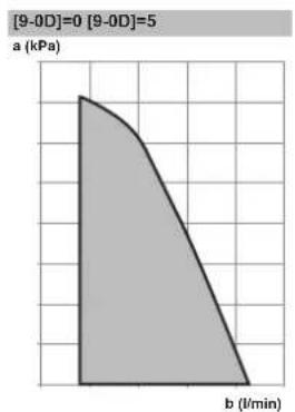
area
| b (l/min) | a (kPa) | | --------- | ------- | | 0 | 5 | | 5 | 4 |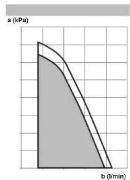
area
| b (l/min) | Value (kPa) | | --------- | ----------- | | 0 | 1 | | 1 | 0.8 | | 2 | 0.6 | | 3 | 0.4 | | 4 | 0.2 | | 5 | 0.0 |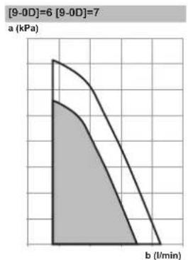
area
| b (l/min) | Value (kPa) | | --------- | ----------- | | 0 | 6 | | 2.5 | 4 |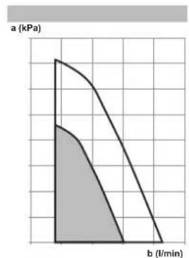
line
| b (l/min) | Curve 1 (kPa) | Curve 2 (kPa) | | --------- | ------------- | ------------- | | 0 | 1.0 | 0.5 | | 1 | 0.8 | 0.3 | | 2 | 0.6 | 0.1 | | 3 | 0.4 | 0.0 | | 4 | 0.2 | 0.0 | | 5 | 0.1 | 0.0 |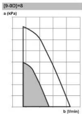
line
| b (l/min) | a (kPa) | | --------- | ------- | | 0 | 8 |a External static pressure b Water flow rate
Pump outside range
When the pump operation function is disabled the pump will stop if the outdoor temperature is higher than the value set by the Space heating off temperature [4-02] or if the outdoor temperature drops below the value set by the Space cooling off temperature [F-01]. When the pump operation is enabled, the pump operation is possible at all outdoor temperatures.
| # Code Description | |
| [4.9] [F-00] Pump operation: | 0: Disabled if outdoor temperature is higher than [4-02] or lower than [F-01] depending on heating/cooling operation mode.1: Possible at all outdoor temperatures. |
Increase around 0^
Use this setting to compensate for possible heat losses of the building due to the evaporation of melted ice or snow. (e.g. in cold region countries).
In heating operation, the desired leaving water temperature is locally increased around an outdoor temperature of 0^ C. This compensation can be selected when using an absolute or a weather dependent desired temperature (see illustration below).
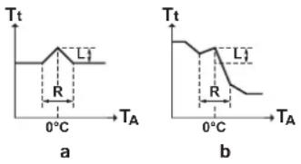
a Absolute desired LWT b Weather dependent desired LWT
| # Code | Description | |
| [4.A] [D-03] Increase around 0°C:0: No1: increase 2°C, span 4°C2: increase 4°C, span 4°C3: increase 2°C, span 8°C4: increase 4°C, span 8°C | ||
Overshoot
This function defines how much the water temperature may rise above the desired leaving water temperature before the compressor stops. The compressor will start up again when the leaving water temperature drops below the desired leaving water temperature. This function is ONLY applicable in heating mode.
| # Code | Description | |
| [4.B] [9-04] Over | rshoot: | 1^ 4^ |
Antifrost
Room frost protection [1.4] prevents the room from getting too cold. For more information about room frost protection, see "9.5.2 Room" [▶ 136].
9.5.6 Tank
Overview
The following items are listed in the submenu:
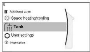
[5] Tank
Setpoint screen
[5.1] Powerful operation
[5.2] Comfort setpoint
[5.3] Eco setpoint
[5.4] Reheat setpoint
[5.5] Schedule
[5.6] Heat up mode
[5.7] Disinfection
[5.8] Maximum
[5.9] Hysteresis
[5.A] Hysteresis
[5.B] Setpoint mode
[5.C] WD curve
[5.D] Margin
![DAIKIN ETVX16S18DA9W - [5] Tank - 1](/content/2026/05/911660/images/8d27da94abffff386b38ba0e7c1bdba1e2bccf7b18bda8e5ff3073d7894745d3.jpg)
INFORMATION
To make tank defrost possible, we recommend a minimum tank temperature of 35^ C.
Tank setpoint screen
You can set the domestic hot water temperature using the setpoint screen. For more information about how to do this, see "9.3.5 Setpoint screen" [▶ 125].
Powerful operation
You can use powerful operation to immediately start heating up the water to the preset value (Storage comfort). However, this consumes extra energy. If powerful operation is active, will be shown on the home screen.
To activate powerful operation
Activate or deactivate Powerful operation as follows:
| 1 Go to [5.1]: Tank >Powerful operation | ###...○ | |
| 2 Turn powerful operation Off or On. | ###...○ | |
Usage example: You immediately need more hot water
If you are in the following situation:
- You already consumed most of your hot water.
- You cannot wait for the next scheduled action to heat up the DHW tank.
Then you can activate DHW powerful operation.
Advantage: The DHW tank immediately starts heating up the water to the preset value (Storage comfort).

INFORMATION
When powerful operation is active, the risk of space heating/cooling and capacity shortage comfort problems is significant. In case of frequent domestic hot water operation, frequent and long space heating/cooling interruptions will happen.
Comfort setpoint
Only applicable when domestic hot water preparation is Schedule only or Schedule + reheat. When programming the schedule, you can make use of the comfort setpoint as a preset value. When you later want to change the storage setpoint, you only have to do it in one place.
The tank will heat up until the storage comfort temperature has been reached. It is the higher desired temperature when a storage comfort action is scheduled.
Additionally, a storage stop can be programmed. This feature puts a stop to tank heating even if the setpoint has NOT been reached. Only program a storage stop when tank heating is absolutely undesirable.
| # Code Description | |
| [5.2] [6-0A] Comfort setpoint:30°C~[6-0E]°C | |
Eco setpoint
The storage economic temperature denotes the lower desired tank temperature. It is the desired temperature when a storage economic action is scheduled (preferably during day).
| # Code Description | ||
| [5.3] [6-0B] Eco | setpoint: | 30^ (50,[6-0E])^ |
Reheat setpoint
Desired reheat tank temperature, used:
- in Schedule + reheat mode, during reheat mode: the guaranteed minimum tank temperature is set by the Reheat setpoint minus the reheat hysteresis. If the tank temperature drops below this value, the tank is heated up.
- during storage comfort, to prioritize the domestic hot water preparation. When the tank temperature rises above this value, domestic hot water preparation and space heating/cooling are executed sequentially.
| # Code Description | |
| [5.4] [6-0C] Reheat setpoint:30°C~min(50,[6-0E])°C | |
Schedule
You can set the tank temperature schedule using the schedule screen. For more information about this screen, see "9.3.7 Schedule screen: Example" [▶ 126].
Heat up mode
The domestic hot water can be prepared in 3 different ways. They differ from each other by the way the desired tank temperature is set and how the unit acts upon it.
| # Code | Description | |
| [5.6] [6-0D] Heat up mode: | 0: Reheat only: Only reheat operation is allowed.1: Schedule + reheat: The domestic hot water tank is heated according to a schedule and between the scheduled heat up cycles, reheat operation is allowed.2: Schedule only: The domestic hot water tank can ONLY be heated according to a schedule. | |
See the operation manual for more details.
Disinfection
Applies only to installations with a domestic hot water tank.
The disinfection function disinfects the domestic hot water tank by periodically heating the domestic hot water to a specific temperature.

CAUTION
The disinfection function settings MUST be configured by the installer according to the applicable legislation.
| # Code | Description | |
| [5.7.1] | [2-01] | Activation:0: No1: Yes |
| [5.7.2] | [2-00] | Operation day:0: Every day1: Monday2: Tuesday3: Wednesday4: Thursday5: Friday6: Saturday7: Sunday |
| [5.7.3] | [2-02] | Start time |
| [5.7.4] | [2-03] | Tank setpoint:60°C |
| [5.7.5] | [2-04] | Duration:40~60 minutes |
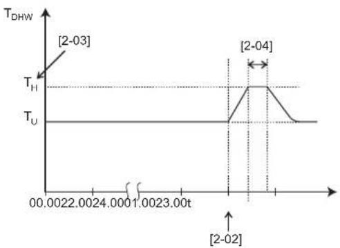
line
| Time (t) | DHW Value | | -------------- | --------- | | 00.0022 | T_H | | 1.0023 | T_U | | 2.0024 | T_H | | 2.04 | T_H (peak) |T_DHW Domestic hot water temperature T_U User setpoint temperature T_H High setpoint temperature [2-03] t Time

WARNING
Be aware that the domestic hot water temperature at the hot water tap will be equal to the value selected in field setting [2-03] after a disinfection operation.
When the high domestic hot water temperature can be a potential risk for human injuries, a mixing valve (field supply) shall be installed at the hot water outlet connection of the domestic hot water tank. This mixing valve shall secure that the hot water temperature at the hot water tap never rise above a set maximum value. This maximum allowable hot water temperature shall be selected according to the applicable legislation.

CAUTION
Be sure that the disinfection function start time [5.7.3] with defined duration [5.7.5] is NOT interrupted by possible domestic hot water demand.

NOTICE
Disinfection mode. Even if you turn OFF tank heating operation ([C.3]: Operation > Tank), disinfection mode will remain active. However, if you turn it OFF while disinfection is running, an AH error occurs.

INFORMATION
In case of error code AH and no interruption of the disinfection function occurred due to domestic hot water tapping, following actions are recommended:
- When the Reheat only or Schedule + reheat mode is selected, it is recommended to program the start-up of the disinfection function at least 4 hours later than the last expected large hot water tapping. This start-up can be set by installer settings (disinfection function).
- When the Schedule only mode is selected, it is recommended to program an Eco action 3 hours before the scheduled start-up of the disinfection function to preheat the tank.

INFORMATION
Disinfection function is restarted in case the domestic hot water temperature drops 5°C below the disinfection target temperature within the duration time.
Maximum DHW temperature setpoint
The maximum temperature that users can select for the domestic hot water. You can use this setting to limit the temperatures at the hot water taps.

INFORMATION
During disinfection of the domestic hot water tank, the DHW temperature can exceed this maximum temperature.

INFORMATION
Limit the maximum hot water temperature according to the applicable legislation.
| # Code Description | |
| [5.8] [6-0E] Maximum: | The maximum temperature that users can select for the domestic hot water. You can use this setting to limit the temperature at the hot water taps.The maximum temperature is NOT applicable during disinfection function. See disinfection function. |
Hysteresis
The following ON hysteresis can be set.
Heat pump ON hysteresis
Applicable when domestic hot water preparation is reheat only. When the tank temperature drops below the reheat temperature minus the heat pump ON hysteresis temperature, the tank heats up to the reheat temperature.
The minimum ON temperature is 20^ C, even if setpoint hysteresis is smaller than 20^ C.
| # Code Description | ||
| [5.9] [6-00] Heat pump ON hysteresis2°C~40°C | ||
Reheat hysteresis
Applicable when domestic hot water preparation is scheduled+reheat. When the tank temperature drops below the reheat temperature minus the reheat hysteresis temperature, the tank heats up to the reheat temperature.
| # Code Description | |
| [5.A] [6-08] Reheat hysteresis | 2^ 20^ |
Setpoint mode
| # Code Description | |
| [5.B] N/A Setpoint mode: | FixedWeather dependent |
WD curve
When weather dependent operation is active the desired tank temperature is determined automatically depending on the averaged outdoor temperature: low outdoor temperatures will result in higher desired tank temperatures as the cold water tap is colder and vice versa.
In case of Schedule only or Schedule + reheat domestic hot water preparation, the storage comfort temperature is weather dependent (according to the weather dependent curve), the storage economic and reheat temperature are NOT weather dependent.
In case of Reheat only domestic hot water preparation, the desired tank temperature is weather dependent (according to the weather dependent curve). During weather dependent operation, the end-user cannot adjust the desired tank temperature on the user interface. Also see "9.4 Weather-dependent curve" [▶ 130].
| # Code Description | |
| [5.C] [0-0E] | WD curve: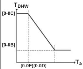 T_DHW : The desired tank temperature. T_a : The (averaged) outdoor ambient temperature [0-0E] : low outdoor ambient temperature: -40^ 5^ [0-0D] : high outdoor ambient temperature: 10^ 25^ [0-0C] : desired tank temperature when the outdoor temperature equals or drops below the low ambient temperature: 45^ [6-0E]^ [0-0B] : desired tank temperature when the outdoor temperature equals or rises above the high ambient temperature: 35^ [6-0E]^ T_DHW : The desired tank temperature. T_a : The (averaged) outdoor ambient temperature [0-0E] : low outdoor ambient temperature: -40^ 5^ [0-0D] : high outdoor ambient temperature: 10^ 25^ [0-0C] : desired tank temperature when the outdoor temperature equals or drops below the low ambient temperature: 45^ [6-0E]^ [0-0B] : desired tank temperature when the outdoor temperature equals or rises above the high ambient temperature: 35^ [6-0E]^ |
Margin
In domestic hot water operation, the following hysteresis value can be set for the heat pump operation:
| # | Code | Description |
| [5.D] | [6-01] | The temperature difference determining the heat pump OFF temperature.Range: 0°C~10°C |
Example: setpoint (T_U)> maximum heat pump temperature—[6-01] (T_HP MAX—[6-01])
| BUH | Backup heater |
| HP | Heat pump. If heating up time by the heat pump takes too long, auxiliary heating by the backup heater can take place |
| T_BUH OFF | Backup heater OFF temperature ( T_U ) |
| T_HP MAX | Maximum heat pump temperature at sensor in domestic hot water tank |
| T_HP OFF | Heat pump OFF temperature ( T_HP MAX-[6-01] ) |
| T_HP ON | Heat pump ON temperature ( T_HP OFF-[6-00] ) |
| T_DHW | Domestic hot water temperature |
| T_U | User setpoint temperature (as set on the user interface) |
| t | Time |
Example: setpoint (T_U)≤ maximum heat pump temperature- [6-01] (T_HPMAX - [6 - 01])
| HP | Heat pump. If heating up time by the heat pump takes too long, auxiliary heating by the backup heater can take place |
| T_HP MAX | Maximum heat pump temperature at sensor in domestic hot water tank |
| T_HP OFF | Heat pump OFF temperature ( T_HP MAX-[6-01] ) |
| T_HP ON | Heat pump ON temperature ( T_HP OFF-[6-00] ) |
| T_DHW | Domestic hot water temperature |
| T_U | User setpoint temperature (as set on the user interface) |
| t | Time |

INFORMATION
The maximum heat pump temperature depends on the ambient temperature. For more information, see the operation range.
9.5.7 User settings
Overview
The following items are listed in the submenu:
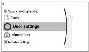
[7] User settings
[7.1] Language
[7.2] Time/date
[7.3] Holiday
[7.4] Quiet
[7.5] Electricity price
[7.6] Gas price
Language
| # Code | Description | |
| [7.1] N/A Language |
Time/date
| # Code Description | |
| [7.2] N/A Set the local time and date | |

INFORMATION
By default, daylight savings time is enabled and clock format is set to 24 hours. If you want to change these settings, you can do this in the menu structure (User settings > Time/date) once the unit is initialised.
Holiday
About holiday mode
During your holiday, you can use the holiday mode to deviate from your normal schedules without having to change them. While holiday mode is active, space heating/cooling operation and domestic hot water operation will be turned off. Room frost protection and anti-legionella operation will remain active.
Typical workflow
Using holiday mode typically consists of the following stages:
1 Setting the starting date and ending date of your holiday.
2 Activating the holiday mode.
To check if holiday mode is activated and/or running
If IR displayed on the home screen, holiday mode is active.
To configure the holiday
| 1 Activate the holiday mode. — | |
| Go to [7.3.1]: User settings >Holiday >Activation.7.3.1ActivationFromTill | ###...○ |
| Select On. | ###...○ |
| 2 Set the first day of your holiday. — | |
| Go to [7.3.2]: From. | ###...○ |
| Select a date. | ○...○○...○ |
| Confirm the changes. | ###...○ |
| 3 Set the last day of your holiday. — | |
| Go to [7.3.3]: Till. | ###...○ |
| Select a date. | ○...○○...○ |
| Confirm the changes. | ###...○ |
Quiet
About quiet mode
You can use quiet mode to decrease the sound of the outdoor unit. However, this also decreases the heating/cooling capacity of the system. There are multiple quiet mode levels.
The installer can:
- Completely deactivate quiet mode
■ Manually activate a quiet mode level - Enable the user to program a quiet mode schedule
If enabled by the installer, the user can program a quiet mode schedule.

INFORMATION
If the outdoor temperature is below zero, we recommend to NOT use the most quiet level.
To check if quiet mode is active
If 1 is displayed on the home screen, quiet mode is active.
To use quiet mode
| 1 | Go to [7.4.1]: User settings >Quiet >Activation. | |
| 2 | Do one of the following: — |
| If you want to... Then... | ||
| Completely deactivate quiet mode | Select Off.Result: The unit never runs in quiet mode. The user cannot change this. | ### |
| Manually activate a quiet mode level | Select Manual. | ### |
| Go to [7.4.3]Leveland select the applicable quiet mode level.Example: Most quiet.Result:The unit always runs in the selected quiet mode level. The user cannot change this. | ### | |
| Enable the user to program a quiet mode schedule | Select Automatic.Result:The unit runs in quiet mode according to a schedule. The user (or you) can program the schedule in [7.4.2]Schedule. For more information about scheduling, see "9.3.7 Schedule screen:Example" [ ▶ 126]. | ### |
Electricity prices and gas price
Only applicable in combination with the bivalent function. See also
"Bivalent" [▶ 189].
| # Code Description | |
| [7.5.1] N/A Electricity price >High | |
| [7.5.2] N/A Electricity price >Medium | |
| [7.5.3] N/A Electricity price >Low | |
| [7.6] N/A Gas price | |

INFORMATION
Electricity price can only be set when bivalent is ON ([9.C.1] or [C-02]). These values can only be set in menu structure [7.5.1], [7.5.2] and [7.5.3]. Do NOT use overview settings.
To set the gas price
| 1 Go to [7.6]: User settings >Gas price. | ###...○ | |
| 2 Select the correct gas price. | ○...○ | |
| 3 Confirm the changes. | ###...○ | |

INFORMATION
Price value ranging from 0.00\~990 valuta/kWh (with 2 significant values).
To set the electricity price
| 1 | Go to [7.5.1]/[7.5.2]/[7.5.3]: User settings > Electricity price > High/Medium/Low. | |
| 2 | Select the correct electricity price. | |
| 3 | Confirm the changes. | |
| 4 | Repeat this for all three electricity prices. — |

INFORMATION
Price value ranging from 0.00\~990 valuta/kWh (with 2 significant values).

INFORMATION
If no schedule is set, the Electricity price for High is taken into account.
To set the electricity price schedule timer
| 1 | Go to [7.5.4]: User settings > Electricity price > Schedule. | |
| 2 | Program the selection using the scheduling screen. You can set the High, Medium and Low electricity prices according to your electricity supplier. | — |
| 3 | Confirm the changes. |

INFORMATION
The values correspond with the electricity price values for High, Medium and Low previously set. If no schedule is set, the electricity price for High is taken into account.
About energy prices in case of an incentive per kWh renewable energy
An incentive can be taken into account when setting the energy prices. Although the running cost can increase, the total operation cost, taking into account the reimbursement will be optimized.

NOTICE
Make sure to modify the setting of the energy prices at the end of the incentive period.
To set the gas price in case of an incentive per kWh renewable energy
Calculate the value for the gas price with the following formula:
- Actual gas price+(Incentive/kWh×0.9)
For the procedure to set the gas price, see "To set the gas price" [▶ 173].
To set the electricity price in case of an incentive per kWh renewable energy
Calculate the value for the electricity price with following formula:
- Actual electricity price+Incentive/kWh
For the procedure to set the electricity price, see "To set the electricity price" [▶ 173].
Example
This is an example and the prices and/or values used in this example are NOT accurate.
| Data Price/kWh | |
| Gas price 4.08 | |
| Electricity price 12.49 | |
| Renewable heat incentive per kWh 5 |
Calculation of the gas price
Gas price=Actual gas price+(Incentive/kWh×0.9)
Gas price=4.08+(5×0.9)
Gas price=8.58
Calculation of the electricity price
Electricity price=Actual electricity price+Incentive/kWh
Electricity price=12.49+5
Electricity price=17.49
| Price Value in breadcrumb | |
| Gas: 4.08 /kWh [7.6]=8.6 | |
| Electricity: 12.49 /kWh [7.5.1]=17 |
9.5.8 Information
Overview
The following items are listed in the submenu:
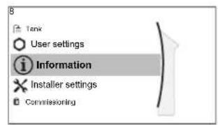
[8] Information
[8.1] Energy data
[8.2] Malfunction history
[8.3] Dealer information
[8.4] Sensors
[8.5] Actuators
[8.6] Operation modes
[8.7] About
[8.8] Connection status
[8.9] Running hours
[8.A] Reset
Dealer information
The installer can fill in his contact number here.
| # Code Description | |
| [8.3] N/A Number | that users can call in case of problems. |
Reset
Reset the configuration settings stored in the MMI (user interface of the indoor unit).
Example: Energy meterings, holiday settings.
| i | INFORMATIONThis does not reset the configuration settings and field settings of the indoor unit. |
| # Code Description | ||
| [8.A] N/A Reset the MMI EEPROM | to factory default | |
Possible read-out information
| In menu... You can read out... | |
| [8.1] Energy data Produced energy, consumed electricity,and consumed gas | |
| [8.2] Malfunction history Malfunction history | |
| [8.3] Dealer information Contact/helpdesk number | |
| [8.4] Sensors Room, tank or domestic hot water,outside, and leaving water temperature(if applicable) | |
| [8.5] Actuators Status/mode of each actuatorExample:Domestic hot water pumpON/OFF | |
| [8.6] Operation modes Current operation modeExample: Defrost/oil return mode | |
| [8.7] About Version information about the system | |
| [8.8] Connection status Information about the connection status of the unit, the room thermostat and the LAN adapter. | |
| [8.9] Running hours Running hours of specific system components |
9.5.9 Installer settings
Overview
The following items are listed in the submenu:
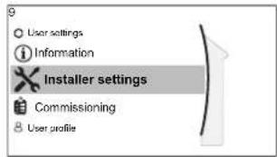
[9] Installer settings
[9.1] Configuration wizard
[9.2] Domestic hot water
[9.3] Backup heater
[9.5] Emergency
[9.6] Balancing
[9.7] Water pipe freeze prevention
[9.8] Benefit kWh power supply
[9.9] Power consumption control
[9.A] Energy metering
[9.B] Sensors
[9.C] Bivalent
[9.D] Alarm output
[9.E] Auto restart
[9.F] Power saving function
[9.G] Disable protections
[9.H] Forced defrost
[9.1] Overview field settings
[9.N] Export MMI settings
Configuration wizard
After first power ON of the system, the user interface will guide you using the configuration wizard. This way you can set the most important initial settings. This way the unit will be able to run properly. Afterwards, more detailed settings can be done via the menu structure if required.
To restart the configuration wizard, go to Installer settings > Configuration wizard [9.1].
Domestic hot water
Domestic hot water
The following setting determines if the system can prepare domestic hot water or not, and which tank is used. This setting is read only.
| # Code Description | ||
| [9.2.1] [E-05] | ^(a) [E-06]^(a) [E-07]^(a) | ▪ IntegratedThe backup heater will also be used for domestic hot water heating. |
(v) Use the menu structure instead of the overview settings. Menu structure setting [9.2.1]
replaces the following 3 overview settings:
• [E-05]: Can the system prepare domestic hot water?
• [E-06]: Is a domestic hot water tank installed in the system?
• [E-07]: What kind of domestic hot water tank is installed?
DHW pump
| # Code Description | |
| [9.2.2] [D-02] DHW pump: | 0: No DHW pump: NOT installed1: Instant hot water: Installed for instant hot water when water is tapped. The user sets the operation timing of the domestic hot water pump using the schedule. Control of this pump is possible with the user interface.2: Disinfection: Installed for disinfection. It runs when the disinfection function of the domestic hot water tank is running. No further settings are needed. |
See also:
- "5.4.4 DHW pump for instant hot water" [▶ 45]
- "5.4.5 DHW pump for disinfection" [▶ 46]
DHW pump schedule
Program a schedule for the DHW pump (only for field supplied domestic hot water pump for secondary return).
Program a domestic hot water pump schedule to determine when to turn on and off the pump.
When turned on, the pump runs and makes sure hot water is instantly available at the tap. To save energy, only turn on the pump during periods of the day when instant hot water is necessary.
Backup heater
Besides the type of backup heater, the voltage, configuration and capacity must be set on the user interface.
The capacities for the different steps of the backup heater must be set for the energy metering and/or power consumption feature to work properly. When measuring the resistance value of each heater, you can set the exact heater capacity and this will lead to more accurate energy data.
Backup heater type
The backup heater is adapted to be connected to most common European electricity grids. The type of backup heater can be viewed but not changed.
| # Code Description | |
| [9.3.1] [E-03]▪ 3: 6V | ▪ 4: 9W |
Voltage
- For a 6V model, this can be set to:
- 230V, 1ph
-230V, 3ph
- For a 9W model, this is fixed to 400V, 3ph.
| # Code Description | |
| [9.3.2] [5-0D] • 0: 230V, 1ph | • 1: 230V, 3ph• 2: 400V, 3ph |
Configuration
The backup heater can be configured in different ways. It can be chosen to have a 1-step only backup heater or a backup heater with 2 steps. If 2 steps, the capacity of the second step depends on this setting. It can also be chosen to have a higher capacity of the second step in emergency.
| # Code Description | |
| [9.3.3] [4-0A] • 0: Relay 1 | • 1: Relay 1 / Relay 1+2• 2: Relay 1 / Relay 2• 3: Relay 1 / Relay 2 Emergency Relay 1+2 |

INFORMATION
Settings [9.3.3] and [9.3.5] are linked. Changing one setting influences the other. If you change one, check if the other is still as expected.

INFORMATION
During normal operation, the capacity of the second step of the backup heater at nominal voltage is equal to [6-03]+[6-04].

INFORMATION
If [4-0A]=3 and emergency mode is active, the power usage of the backup heater is maximal and equal to 2×[6-03]+[6-04] .

INFORMATION
Only for systems with integrated domestic hot water tank: If the storage temperature setpoint is higher than 50^ C, Daikin recommends NOT to disable the backup heater second step because it will have a big impact on the required time for the unit to heat up the domestic hot water tank.
Capacity step 1
| # Code Description | |
| [9.3.4] [6-03] • The capacity of | the first step of the backup heater at nominal voltage. |
Additional capacity step 2
| # Code Description | |
| [9.3.5] [6-04] • The capacity difference between the second and first step of the backup heater at nominal voltage. Nominal value depends on backup heater configuration. | |
Equilibrium
| # Code Description | ||
| [9.3.6] [5-00] Equilibrium: Is | backup heater operationallowed above equilibrium temperature during space heating operation?1: NOT allowed0: Allowed | |
| [9.3.7] [5-01] Equilibrium | temperature: Outdoor temperature below which operation of the backup heater is allowed.Range: -15^ 35^ | |

INFORMATION
Above 10^ C ambient temperature, the heat pump will operate until 55^ C. Configuring a higher setpoint with an ambient temperature that is higher than the set equilibrium temperature will prevent the backup heater from assisting. The backup heater will ONLY assist if you increase the equilibrium temperature [5-01] to the required ambient temperature you need to reach the higher setpoint.
Operation
| # Code Description | |
| [9.3.8] [4-00] Backup heater operation:0: Restricted1: Allowed2: Only DHW Backup heater operation is enabled for domestic hot water and disabled for space heating. | |

INFORMATION
Only for systems with integrated domestic hot water tank: If backup heater operation during space heating needs to be limited but can be allowed for domestic hot water operation, then set [4-00] to 2.
Emergency
Emergency
To keep energy consumption low, we recommend to set Emergency to auto SH reduced/DHW off if the house is unattended for longer periods.
| # Code Description | |
| [9.5.1] [4-06]▪ 0: Manual | ▪ 1: Automatic▪ 2: auto SH reduced/DHW on▪ 3: auto SH reduced/DHW off▪ 4: auto SH normal/DHW off |

INFORMATION
The auto emergency setting can be set in the menu structure of the user interface only.

INFORMATION
If a heat pump failure occurs and Emergency is set to Manual, the room frost protection function, the underfloor heating screed dryout function, and the water pipe antifreeze function will remain active even if the user does NOT confirm emergency operation.
HP forced off
HP forced off mode can be activated to allow the backup heater to provide domestic hot water and space heating. Cooling is NOT possible when this mode is activated.
| # Code Description | |
| [9.5.2] [7-06] Activation of the HP forced off mode:0: disabled1: enabled | |
Glycol filled system
Glycol Filled system
This setting gives the installer the possibility to indicate whether the system is filled with glycol or water. This is important in case glycol is used to protect the water circuit against freezing. If NOT set correctly, the liquid in the piping can freeze.
| # Code Description | |
| N/A [E-0D] Glycol Filled system: Is the system filled with glycol?▪ 0: No▪ 1: Yes | |
Balancing
Priorities
For systems with an integrated domestic hot water tank.
| # Code Description | |
| [9.6.1] [5-02] Space heating priority: Defines whether backup heater will assist the heat pump during domestic hot water operation. For optimal operation and lowest power consumption, it is strongly recommended to keep the default setting (0). If the backup heater operation is limited ([4-00]=0) and the outdoor temperature is lower than setting [5-03], the domestic hot water will not be heated with the backup heater. | |
| [9.6.2] [5-03] Priority temperature: Used for calculation of anti-recycling timer. If [5-02]=1, it defines the outdoor temperature below which the backup heater will assist during domestic hot water heating. [5-01] Equilibrium temperature and [5-03] Space heating priority temperature are related to backup heater. So, you must set [5-03] equal or a few degrees higher than [5-01]. | |
| [9.6.3] [5-04] Offset BSH setpoint: Setpoint correction for domestic hot water temperature: setpoint correction for the desired domestic hot water temperature, to be applied at low outdoor temperature when space heating priority is enabled. The corrected (higher) setpoint will make sure that the total heat capacity of the water in the tank remains approximately unchanged, by compensating for the colder bottom water layer of the tank (because the heat exchanger coil is not operational) with a warmer top layer. Range: 0°C~20°C | |
Timers
For simultaneous space and domestic hot water operation request.
[8-02]: Anti-recycle timer
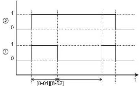
line
| Time | Value | |---|---| | [8-01] | 1 | | [8-02] | 1 | | End | 1 |1 Heat pump domestic water heating mode (1=active, 0=not active)
2 Hot water request for heat pump (1=request, 0=no request)
t Time
[8-04]: Additional timer at [4-02]/[F-01]
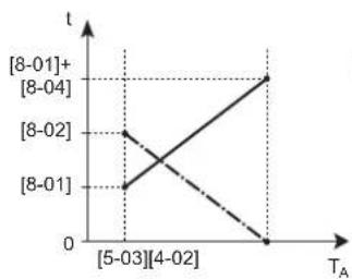
line
| T_A | t | |---|---| | [5-03] | 8-01 | | [4-02] | 8-02 | | [8-01]+ | 8-01+ |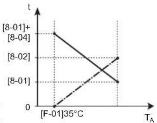
line
| T_A | t | |---|---| | [8-01]+ | 0 | | [8-04] | 0 | | [8-02] | 0 | | [8-01] | 0 | | [F-01]35℃ | 0 |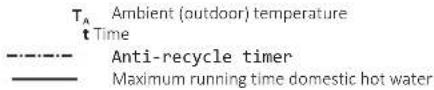
| # Code Description | |
| [9.6.4] [8-02] Anti-recycle | timer: Minimum time between two cycles for domestic hot water. The actual anti-recycling time also depends on setting [8-04].Range: 0~10 hoursRemark: The minimum time is 0.5 hours even when the selected value is 0. |
| [9.6.5] [8-00] Minimum running | ng timer:Do NOT change. |
| [9.6.6] [8-01] Maximum running | ng timer for domestic hot water operation. Domestic hot water heating stops even when the target domestic hot water temperature is NOT reached. The actual maximum running time also depends on setting [8-04].When Control=Room thermostat: This preset value is only taken into account if there is a request for space heating or cooling. If there is NO request for space heating/cooling the tank is heated until the setpoint has been reached.When Control≠Room thermostat: This preset value is always taken into account.Range: 5~95 minutesRemark: It is NOT allowed to set [8-01] to a value below 10 minutes. |
| [9.6.7] [8-04] Additional ti | mer: Additional running time for the maximum running time depending on the outdoor temperature [4-02] or [F-01].Range: 0~95 minutes |
Water pipe freeze prevention
Only relevant for installations with water piping outdoors. This function tries to protect outdoor water piping from freezing.
| # Code Description | ||
| [9.7] | [4-04] | Water pipe freeze prevention:▪ 0: Intermittent (read only) |

NOTICE
Water pipe freeze prevention. Even if you turn OFF space heating/cooling operation ([C.2]: Operation > Space heating/cooling), water pipe freeze prevention –if enabled– will remain active.
Preferential kWh rate power supply

INFORMATION
The preferential kWh rate power supply contact is connected to the same terminals (X5M/9+10) as the safety thermostat. Thus, the system can have EITHER preferential kWh rate power supply OR a safety thermostat.
| # Code Description | |
| [9.8.1] [D-01] Connection to a Benefit kWh power supplyor a Safety thermostat:0 No: The outdoor unit is connected to a normal power supply.1 Open: The outdoor unit is connected to a preferential kWh rate power supply. When the preferential kWh rate signal is sent by the electricity company, the contact will open and the unit will go in forced off mode. When the signal is released again, the voltage-free contact will close and the unit will restart operation. Therefore, always enable the auto restart function.2 Closed: The outdoor unit is connected to a preferential kWh rate power supply. When the preferential kWh rate signal is sent by the electricity company, the contact will close and the unit will go in forced off mode. When the signal is released again, the voltage-free contact will open and the unit will restart operation. Therefore, always enable the auto restart function.3 Safety thermostat: A safety thermostat is connected to the system (normal closed contact) | |
| [9.8.2] [D-00] Allow heater: | Which heaters are allowed to operate during preferential kWh rate power supply?▪ 0 No: None▪ 1 Only BSH: Booster heater only▪ 2 Only BUH: Backup heater only▪ 3 All: All heatersSee table below.Setting 2 is only meaningful if the preferential kWh rate power supply is of type 1 or indoor unit is connected to a normal kWh rate power supply (via X2M/5-6) and the backup heater is NOT connected to the preferential kWh rate power supply. |
| [9.8.3] [D-05] Allow pump: | ▪ 0 No: Pump is forced off▪ 1 Yes: No limitation |
Do NOT use 1 or 3. Setting [D-00] to 1 or 3 when [D-01] is set to 1 or 2 will reset [D-00] back to 0, as the system does not have a booster heater. Only set [D-00] to the values in the table below:
| [D-00] Backup | heater Compressor | |
| 0 Forced OFF Forced OFF | ||
| 2 Allowed | ||
Power consumption control
Power consumption control
See "5 Application guidelines" [▶ 27] for detailed information about this functionality.
| # Code Description | |
| [9.9.1] [4-08] | Power consumption control:0 No: Disabled.1 Continuous: Enabled: You can set one power limitation value (in A or kW) to which the system power consumption will be limited for all the time.2 Inputs: Enabled: You can set up to four different power limitation values (in A or kW) to which the system power consumption will be limited when the corresponding digital input asks. |
| [9.9.2] [4-09] | Type:0 Amp: The limitation values are set in A.1 kW: The limitation values are set in kW. |
Limit when [9.9.1]=Continuous and [9.9.2]=Amp:
| # Code Description | |
| [9.9.3] [5-05] Limit: Only applicable in case of full time current limitation mode.0 A~50 A | |
Limits when [9.9.1]=Inputs and [9.9.2]=Amp:
| # Code Description | |
| [9.9.4] [5-05] Limit 1: 0 A~50 A | |
| [9.9.5] [5-06] Limit 2: 0 A~50 A | |
| [9.9.6] [5-07] Limit 3: 0 A~50 A | |
| [9.9.7] [5-08] Limit 4: 0 A~50 A |
Limit when [9.9.1]=Continuous and [9.9.2]=kW:
| # Code Description | |
| [9.9.8] [5-09] Limit: Only applicable in case of full time power limitation mode. 0 kW~20 kW | |
Limits when [9.9.1]=Inputs and [9.9.2]=kW:
| # Code Description | ||
| [9.9.9] [5-09] Limit | 1: 0 kW~20 | kW |
| [9.9.A] [5-0A] Limit | 2: 0 kW~20 | kW |
| [9.9.B] [5-0B] Limit | 3: 0 kW~20 | kW |
| [9.9.C] [5-0C] Limit | 4: 0 kW~20 | kW |
Priority heater
| # Code Description | |
| [9.9.D] [4-01] Power consumption control DISABLED[4-08]=00 None: Backup heater and booster heater can operate simultaneously.1 Booster heater: The booster heater is prioritised.2 Backup heater: The backup heater is prioritised.Power consumption control ENABLED[4-08]=1/20 None: Depending on the power limitation level, the booster heater will be limited first, before the backup heater is limited.1 Booster heater: Depending on the power limitation level, the backup heater will be limited first, before the booster heater is limited.2 Backup heater: Depending on the power limitation level, the booster heater will be limited first, before the backup heater is limited. | |
Note: In case power consumption control is DISABLED (for all models) the setting [4-01] defines whether backup heater and booster heater can operate simultaneously, or if the booster heater/backup heater has priority over the backup heater/booster heater.
In case power consumption control is ENABLED, the setting [4-01] defines the priority of the electrical heaters depending on applicable limitation.
BBR16
See "5.6.4 BBR16 power limitation" [▶ 53] for detailed information about this functionality.

INFORMATION
Restriction: BBR16 settings are only visible when the language of the user interface is set to Swedish.

NOTICE
2 weeks to change. After you activated BBR16, you only have 2 weeks to change its settings (BBR16 activation and BBR16 power limit). After 2 weeks, the unit freezes these settings.
Note: This is different from the permanent power limitation, which is always changeable.
BBR16 activation
| # Code Description | |
| [9.9.F] [7-07] BBR16 activation:0: disabled1: enabled | |
BBR16 power limit
| # Code Description | ||
| [9.9.G] [N/A] BBR16 power lim | it: This setting can onlybe modified via the menu structure.▪ 0 kW~25 kW, step 0.1 kW | |
Energy metering
Energy metering
If energy metering is performed by the use of external power meters, configure the settings as described below. Select the pulse frequency output of each power meter in accordance with the power meter specifications. It is possible to connect up to 2 power meters with different pulse frequencies. If only 1 or no power meter is used, select 'None' to indicate the corresponding pulse input is NOT used.
| # Code Description | |
| [9.A.1] [D-08] Electricity meter 1:0 None: NOT installed1 1/10kWh: Installed2 1/kWh: Installed3 10/kWh: Installed4 100/kWh: Installed5 1000/kWh: Installed | |
| [9.A.2] [D-09] Electricity meter 2:0 None: NOT installed1 1/10kWh: Installed2 1/kWh: Installed3 10/kWh: Installed4 100/kWh: Installed5 1000/kWh: Installed | |
Sensors
External sensor
| # Code Description | |
| [9.B.1] [C-08] External sensor | When an optional external ambient sensor is connected, the type of the sensor must be set.0 None: NOT installed. The thermistor in the dedicated Human Comfort Interface and in the outdoor unit are used for measurement.1 Outdoor: Connected to PCB of the indoor unit measuring the outdoor temperature.Remark: For some functionality, the temperature sensor in the outdoor unit is still used.2 Room: Connected to PCB of the indoor unit measuring the indoor temperature. The temperature sensor in the dedicated Human Comfort Interface is NOT used anymore.Remark: This value has only meaning in room thermostat control. |
Ext. amb. sensor offset
ONLY applicable in case an external outdoor ambient sensor is connected and configured.
You can calibrate the external outdoor ambient temperature sensor. It is possible to give an offset to the thermistor value. This setting can be used to compensate for situations where the external outdoor ambient sensor cannot be installed on the ideal installation location.
| # | Code | Description |
| [9.B.2] | [2-0B] | Ext. amb. sensor offset: Offset on the ambient temperature measured on the external outdoor temperature sensor.-5°C~5°C, step 0.5°C |
Averaging time
The average timer corrects the influence of ambient temperature variations. The weather-dependent setpoint calculation is done on the average outdoor temperature.
The outdoor temperature is averaged over the selected time period.
| # | Code Description |
| [9.B.3] [1-0A] | Averaging time:0: No averaging1: 12 hours2: 24 hours3: 48 hours4: 72 hours |
Bivalent
Bivalent
Only applicable in case of auxiliary boiler.
About bivalent
The purpose of this function is to determine which heating source can/will provide the space heating, either the heat pump system or the auxiliary boiler.
| # Code Description | |
| [9.C.1] [C-02] Bivalent: Indicates if the space heating is also performed by means of another heat source than the system.▪ 0 No: Not installed▪ 1 Yes: Installed. The auxiliary boiler (gas boiler, oil burner) will operate when the outdoor ambient temperature is low. During bivalent operation, the heat pump is turned off. Set this value in case an auxiliary boiler is used. | |
- If Bivalent is enabled: When the outdoor temperature drops below the bivalent ON temperature (fixed or variable based on energy prices), the space heating by the indoor unit stops automatically and the permission signal for the auxiliary boiler is active.
- If Bivalent is disabled: Space heating is only done by the indoor unit within the operation range. The permission signal for the auxiliary boiler is always inactive.
The switch-over between the heat pump system and the auxiliary boiler is based on the following settings:
[C-03] and [C-04]
Electricity and gas prices ([7.5.1], [7.5.2], [7.5.3], and [7.6])
[C-03], [C-04], and T_calc
Based on the settings above, the heat pump system calculates a value T_calo , which is variable between [C-03] and [C-03]+[C-04].
![a 3°C b [C-03] Tcalc [C-03]+[C-04] TA](/content/2026/05/911660/images/3cf2409e6eb5c923045042a8dc552829c0df2f3d10b78dcb61b4838ee0419624.jpg)
T_A Outdoor temperature
T_calc Bivalent ON temperature (variable). Below this temperature, the auxiliary boiler will always be ON. T_cac can never go below [C-03] or above [C-03]+[C-04].
3°C Fixed hysteresis to prevent too much switching between heat pump system and auxiliary boiler
a Auxiliary boiler active
b Auxiliary boiler inactive
| If the outdoor temperature... | Then... | |
| Space heating by the heat pump system... | Bivalent signal for the auxiliary boiler is... | |
| Drops below T_calc | Stops Active | |
| Rises above T_calc +3°C Starts | Inactive | |

INFORMATION
- The bivalent operation function has no impact on the domestic water heating mode. The domestic hot water is still and only heated by the indoor unit.
- The permission signal for the auxiliary boiler is located on the EKRP1HBAA (digital I/O PCB). When it is activated, the contact X1, X2 is closed and open when it is deactivated. See illustration below for the schematic location of this contact.
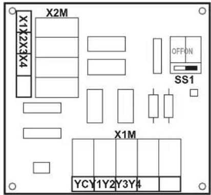
| # Code | Description | |
| 9.C.3 [C-03] Range | ge: -25^ 25^ | (step: 1^ ) |
| 9.C.4 [C-04] Range | ge: 2^ 10^ (step: 1^ )The higher the value of [C-04], the higher the accuracy of the switch-over between the heat pump system and the auxiliary boiler. | |
To determine the value of [C-03], proceed as follows:
1 Determine the COP (= coefficient of performance) using the formula:
| Formula Example | |
| COP = (Electricity price / gas price)(a) × boiler efficiency | If:• Electricity price: 20 c€/kWh• Gas price: 6 c€/kWh• Boiler efficiency: 0.9Then: COP = (20/6)×0.9 = 3 |
[a] Make sure to use the same units of measurement for the electricity price and gas price (example: both c€/kWh).
2 Determine the value of [C-03] using the graph. For an example, see the table legend.
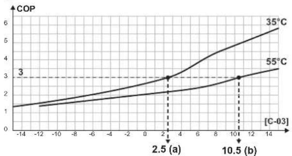
line
| [C-03] | COP (35°C) | COP (55°C) | | ------ | ---------- | ---------- | | -14 | 1.0 | 1.0 | | -12 | 1.2 | 1.2 | | -10 | 1.4 | 1.4 | | -8 | 1.6 | 1.6 | | -6 | 1.8 | 1.8 | | -4 | 2.0 | 2.0 | | -2 | 2.2 | 2.2 | | 0 | 2.4 | 2.4 | | 2 | 2.6 | 2.6 | | 4 | 3.0 | 2.8 | | 6 | 3.5 | 3.0 | | 8 | 4.0 | 3.2 | | 10 | 4.5 | 3.4 | | 12 | 5.0 | 3.6 | | 14 | 5.5 | 3.8 |a [C-03]=2.5 in case of COP=3 and LWT=35°C
b [C-03]=10.5 in case of COP=3 and LWT=55°C

NOTICE
Make sure to set the value of [5-01] at least 1°C higher than the value of [C-03].
Electricity and gas prices

INFORMATION
To set electricity and gas price values, do NOT use overview settings. Set them in the menu structure instead ([7.5.1], [7.5.2], [7.5.3], and [7.6]). For more information on how to set the energy prices, see the operation manual and the user reference guide.

INFORMATION
Solar panels. If solar panels are used, set the electricity price value very low to promote the use of the heat pump.
| # Code Description | ||
| [7.5.1] N/A User | settings > | Electricity price>High |
| [7.5.2] N/A User | settings > | Electricity price>Medium |
| [7.5.3] N/A User | settings > | Electricity price>Low |
| [7.6] N/A User | settings >Gas price | |
Alarm output
Alarm output
| # Code Description | |
| [9.D] [C-09] Alarm output: Indicates the logic of the alarm output on the digital I/O PCB during malfunctioning.0 Abnormal: The alarm output will be powered when an alarm occurs. By setting this value, a distinction is made between the detection of an alarm, and the detection of a power failure.1 Normal: The alarm output will NOT be powered when an alarm occurs.See also table below (Alarm output logic). | |
Alarm output logic
| [C-09] | Alarm No alarm | No power | supply to unit |
| 0 | Closed output | Open output | Open output |
| 1 | Open output | Closed output |
Auto restart
Auto restart
When power returns after a power supply failure, the auto restart function reapplies the remote controller settings at the time of the power failure. Therefore, it is recommended to always enable the function.
If the preferential kWh rate power supply is of the type that power supply is interrupted, always enable the auto restart function. Continuous indoor unit control can be guaranteed independent of the preferential kWh rate power supply status, by connecting the indoor unit to a normal kWh rate power supply.
| # Code Description | |
| [9.E] [3-00] Auto restart: | 0: Manual1: Automatic |
Power saving function
Power saving function

NOTICE
Power saving function. The power saving function is only applicable for V3 models. If you want to use the power saving function, on the outdoor unit PCB make sure to connect X804A to X806A. For more information, see "In case of V3 models" [▶ 93].
Defines whether the outdoor unit power supply can be interrupted (internally by indoor unit control) during stand-still conditions (no space heating/cooling nor domestic hot water demand). The final decision to allow power interruption of the outdoor unit during standstill depends on the ambient temperature, compressor conditions and minimum internal timers.
To enable the power saving function setting, [E-08] needs to be enabled on the user interface.
| # Code Description | |
| [9.F] [E-08] Power saving function for outdoor unit:0: No1: Yes | |
Disable protections

INFORMATION
Protective functions – "Installer-on-site mode". The software is equipped with protective functions, such as room antifrost. The unit automatically runs these functions when necessary.
During installation or service this behaviour is undesired. Therefore, the protective functions can be disabled:
- At first power-on: The protective functions are disabled by default. After 36 h they will be automatically enabled.
- Afterwards: An installer can manually disable the protective functions by setting [9.G]: Disable protections=Yes. After his work is done, he can enable the protective functions by setting [9.G]: Disable protections=No.
| # Code Description | |
| [9.G] N/A Disable protections:0: No1: Yes | |
Forced defrost
Forced defrost
Manually start a defrost operation.
| # Code Description | |
| [9.H] N/A Do you want to start a defrost operation?BackOK |

NOTICE
Forced defrost start-up. You can only start forced defrost when the heating operation has been running for a while.
Overview field settings
All settings can be done using the menu structure. If for any reason it is required to change a setting using the overview settings, then the overview settings can be accessed in the field settings overview [9.1]. See "To modify an overview setting" [▶ 118].
Export MMI settings
About exporting the configuration settings
Export the configuration settings of the unit to a USB memory stick, via the MMI (the user interface of the indoor unit). When troubleshooting, these settings can be provided to our Service department.
| # Code Description | |
| [9.N] N/A Your | MMI settings will be exported to the connected storage device:BackOK |
To export MMI settings
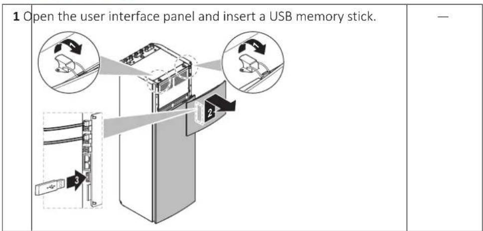
| 2 On the user interface, go to [9.N] Export MMI settings. | ### | |
| 3 Select OK. | ### | |
| 4 Remove the USB memory stick and close the user interface panel. | — | |
9.5.10 Commissioning
Overview
The following items are listed in the submenu:
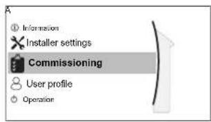
[A] Commissioning
[A.1] Operation test run
[A.2] Actuator test run
[A.3] Air purge
[A.4] UFH screed dryout
About commissioning
See: "10 Commissioning" [▶ 199]
9.5.11 Operation
Overview
The following items are listed in the submenu:
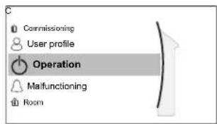
[C] Operation
[C.1] Room
[C.2] Space heating/cooling
[C.3] Tank
To enable or disable functionalities
In the operation menu, you can separately enable or disable functionalities of the unit.
| # Code Description | |
| [C.1] N/A Room: | |
| [C.2] N/A Space heating/cooling: | |
| [C.3] N/A Tank: |
9.5.12 WLAN adapter

INFORMATION
Restriction: WLAN adapter settings are only visible when a WLAN adapter is installed.
Overview
The following items are listed in the submenu:
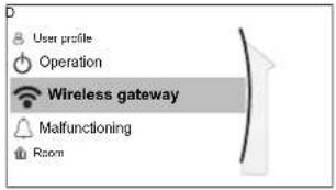
[D] Wireless gateway
[D.1] Mode
[D.2] WPS
[D.3] Reset
[D.4] Device info
About the WLAN adapter
The wireless LAN adapter connects the heat pump system to the internet. The user can then control the heat pump system via the Daikin Residential Controller app.
This needs the following components:
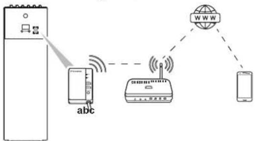
flowchart
graph TD
    A["Server"] -->|abc| B["Wireless Device"]
    B --> C["Mobile Device"]
    C --> D["Network"]
    D --> E["Internet"]
    style A fill:#f9f,stroke:#333
    style B fill:#ccf,stroke:#333
    style C fill:#cfc,stroke:#333
    style D fill:#fcc,stroke:#333
    style E fill:#ffc,stroke:#333
| a WLAN adapter The WLAN | adapter needs to be installed by the installer on the indoor unit (on the inside of the front panel). See:Installation manual of the WLAN adapterAddendum book for optional equipment |
| b Router Field supply. | |
c Smartphone + app The Dai | ikin Residential Controller app needs to be installed on the user's smartphone. See:http://www.onlinecontroller.daikineurope.com/ |
Configuration
To configure the Daikin Residential Controller app, follow the in-app instructions. While doing this, the following actions and information are needed on the user interface of the indoor unit:
Mode: Turn AP mode ON (= WLAN adapter active as access point) or OFF.
| # Code | Description | |
| [D.1] N/A Enable AP mode: | NoYes | |
WPS: Connect the WLAN adapter to the router.
| # Code | Description | |
| [D.2] N/A Connect to home | network:BackOK | |
Reset: Reset the WLAN adapter.
| # Code | Description | |
| [D.3] N/A Reset | the gateway:BackOK | |
Device info: Consult information about the WLAN adapter.
| # Code | Description | |
| [D.4] N/A Device info: | SSIDMAC addressSerial number | |
9.6 Menu structure: Overview user settings
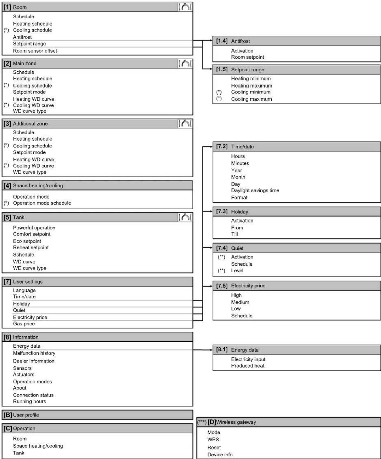
flowchart
graph TD
    A["[1"] Room] --> B["Schedule"]
    B --> C["Heating schedule"]
    C --> D["Cooling schedule"]
    D --> E["Antifrost"]
    E --> F["Setpoint range"]
    F --> G["Room sensor offset"]

    H["[2"] Main zone] --> I["Schedule"]
    I --> J["Heating schedule"]
    J --> K["Cooling schedule"]
    K --> L["Setpoint mode"]
    L --> M["Heating WD curve"]
    M --> N["Cooling WD curve"]
    N --> O["WD curve type"]

    P["[3"] Additional zone] --> Q["Schedule"]
    Q --> R["Heating schedule"]
    R --> S["Cooling schedule"]
    S --> T["Setpoint mode"]
    T --> U["Heating WD curve"]
    U --> V["Cooling WD curve"]
    V --> W["WD curve type"]

    X["[4"] Space heating/cooling] --> Y["Operation mode"]
    Y --> Z["Operation mode schedule"]

    AA["[5"] Tank] --> AB["Powerful operation"]
    AB --> AC["Comfort setpoint"]
    AC --> AD["Eco setpoint"]
    AD --> AE["Reheat setpoint"]
    AE --> AF["Schedule"]
    AF --> AG["WD curve"]
    AG --> AH["WD curve type"]

    AI["[7"] User settings] --> AJ["Language"]
    AJ --> AK["Time/date"]
    AK --> AL["Holiday"]
    AL --> AM["Quiet"]
    AM --> AN["Electricity price"]
    AN --> AO["Gas price"]

    AP["[8"] Information] --> AQ["Energy data"]
    AQ --> AR["Malfunction history"]
    AR --> AS["Dealer information"]
    AS --> AT["Sensors"]
    AT --> AU["Actuators"]
    AU --> AV["Operation modes"]
    AV --> AW["About"]
    AW --> AX["Connection status"]
    AX --> AY["Running hours"]

    AZ["[B"] User profile] --> BA["Operation"]
    BA --> BB["Room"]
    BB --> BC["Space heating/cooling"]
    BC --> BD["Tank"]

    BE["[1.4"] Antifrost] --> BF["Activation"]
    BF --> BG["Room setpoint"]

    BH["[1.5"] Setpoint range] --> BI["Heating minimum"]
    BI --> BJ["Heating maximum"]
    BJ --> BK["(*) Cooling minimum"]
    BJ --> BL["(*) Cooling maximum"]

    BM["[7.2"] Time/date] --> BN["Hours"]
    BN --> BO["Minutes"]
    BO --> BP["Year"]
    BP --> BQ["Month"]
    BQ --> BR["Day"]
    BR --> BS["Daylight savings time"]
    BS --> BT["Format"]

    BU["[7.3"] Holiday] --> BV["Activation"]
    BV --> BW["From"]
    BW --> BX["Till"]

    BY["[7.4"] Quiet] --> BZ["(**) Activation"]
    BZ --> CA["Schedule"]
    CA --> CB["(**) Level"]

    CC["[7.5"] Electricity price] --> CD["High"]
    CD --> CE["Medium"]
    CE --> CF["Low"]
    CF --> CG["Schedule"]

    DH["[8.1"] Energy data] --> DI["Electricity input"]
    DI --> DJ["Produced heat"]

    BK -.-> BI
Setpoint screen
(*) Only applicable for reversible models, or heating only models + conversion kit
(**) Only accessible by installer
(***) Only applicable when WLAN adapter is installed

INFORMATION
Depending on the selected installer settings and unit type, settings will be visible/invisible.
9.7 Menu structure: Overview installer settings
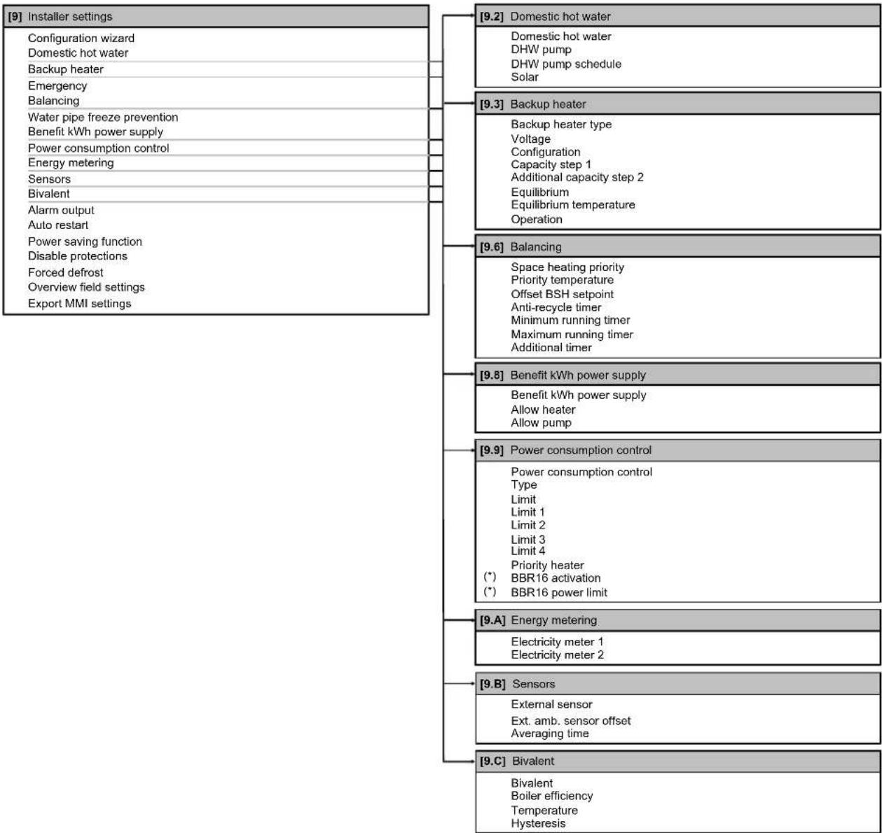
flowchart
graph TD
    A["[9"] Installer settings] --> B["[9.2"] Domestic hot water]
    A --> C["[9.3"] Backup heater]
    A --> D["[9.6"] Balancing]
    A --> E["[9.8"] Benefit kWh power supply]
    A --> F["[9.9"] Power consumption control]
    A --> G["[9.A"] Energy metering]
    A --> H["[9.B"] Sensors]
    A --> I["[9.C"] Bivalent]

    B --> B1["Configuration wizard"]
    B --> B2["Domestic hot water"]
    B --> B3["Backup heater"]
    B --> B4["Emergency"]
    B --> B5["Balancing"]
    B --> B6["Water pipe freeze prevention"]
    B --> B7["Benefit kWh power supply"]
    B --> B8["Power consumption control"]
    B --> B9["Energy metering"]
    B --> B10["Sensors"]
    B --> B11["Bivalent"]
    B --> B12["Alarm output"]
    B --> B13["Auto restart"]
    B --> B14["Power saving function"]
    B --> B15["Disable protections"]
    B --> B16["Forced defrost"]
    B --> B17["Overview field settings"]
    B --> B18["Export MMI settings"]

    C --> C1["Domestic hot water"]
    C --> C2["DHW pump"]
    C --> C3["DHW pump schedule"]
    C --> C4["Solar"]

    D --> D1["Backup heater type"]
    D --> D2["Voltage"]
    D --> D3["Configuration"]
    D --> D4["Capacity step 1"]
    D --> D5["Additional capacity step 2"]
    D --> D6["Equilibrium"]
    D --> D7["Equilibrium temperature"]
    D --> D8["Operation"]

    E --> E1["Space heating priority"]
    E --> E2["Priority temperature"]
    E --> E3["Offset BSH setpoint"]
    E --> E4["Anti-recycle timer"]
    E --> E5["Minimum running timer"]
    E --> E6["Maximum running timer"]
    E --> E7["Additional timer"]

    F --> F1["Benefit kWh power supply"]
    F --> F2["Allow heater"]
    F --> F3["Allow pump"]

    G --> G1["Electricity meter 1"]
    G --> G2["Electricity meter 2"]

    H --> H1["External sensor"]
    H --> H2["Ext. amb. sensor offset"]
    H --> H3["Averaging time"]

    I --> I1["Bivalent"]
    I --> I2["Boiler efficiency"]
    I --> I3["Temperature"]
    I --> I4["Hysteresis"]
(*) Only applicable in Swedish language.

INFORMATION
Solar kit settings are shown but are NOT applicable for this unit. Settings shall NOT be used or changed.

INFORMATION
Depending on the selected installer settings and unit type, settings will be visible/invisible.
10 Commissioning

NOTICE
General commissioning checklist. Next to the commissioning instructions in this chapter, a general commissioning checklist is also available on the Daikin Business Portal (authentication required).
The general commissioning checklist is complementary to the instructions in this chapter and can be used as a guideline and reporting template during the commissioning and hand-over to the user.

NOTICE
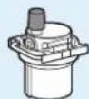

Make sure both air purge valves (one on the magnetic filter and one on the backup heater) are open.
All automatic air purge valves must remain open after commissioning.

INFORMATION
Protective functions – "Installer-on-site mode". The software is equipped with protective functions, such as room antifrost. The unit automatically runs these functions when necessary.
During installation or service this behaviour is undesired. Therefore, the protective functions can be disabled:
- At first power-on: The protective functions are disabled by default. After 12 h they will be automatically enabled.
- Afterwards: An installer can manually disable the protective functions by setting [9.G]: Disable protections=Yes. After his work is done, he can enable the protective functions by setting [9.G]: Disable protections=No.
In this chapter
10.1 Overview: Commissioning.... 199
10.2 Precautions when commissioning.... 200
10.3 Checklist before commissioning.... 200
10.4 Checklist during commissioning.... 201
10.4.1 Minimum flow rate 201
10.4.2 Air purge function 201
10.4.3 Operation test run.... 203
10.4.4 Actuator test run 204
10.4.5 Underfloor heating screed dryout 205
10.1 Overview: Commissioning
This chapter describes what you have to do and know to commission the system after it is installed and configured.
Typical workflow
Commissioning typically consists of the following stages:
1 Checking the "Checklist before commissioning".
2 Performing an air purge.
3 Performing a test run for the system.
4 If necessary, performing a test run for one or more actuators.
5 If necessary, performing an underfloor heating screed dryout.
10.2 Precautions when commissioning

INFORMATION
During the first running period of the unit, the required power may be higher than stated on the nameplate of the unit. This phenomenon is caused by the compressor, that needs a continuous run time of 50 hours before reaching smooth operation and stable power consumption.

NOTICE
ALWAYS operate the unit with thermistors and/or pressure sensors/switches. If NOT, burning of the compressor might be the result.
10.3 Checklist before commissioning
After the installation of the unit, first check the items listed below. Once all checks are fulfilled, the unit must be closed. Power-up the unit after it is closed.
| You read the complete installation instructions, as described in the installer reference guide. | |
| The indoor unit is properly mounted. | |
| The outdoor unit is properly mounted. | |
| The following field wiring has been carried out according to this document and the applicable legislation:Between the local supply panel and the outdoor unitBetween indoor unit and outdoor unitBetween the local supply panel and the indoor unitBetween the indoor unit and the valves (if applicable)Between the indoor unit and the room thermostat (if applicable) | |
| The system is properly earthed and the earth terminals are tightened. | |
| The fuses or locally installed protection devices are installed according to this document, and have NOT been bypassed. | |
| The power supply voltage matches the voltage on the identification label of the unit. | |
| There are NO loose connections or damaged electrical components in the switch box. | |
| There are NO damaged components or squeezed pipes on the inside of the indoor and outdoor units. | |
| Backup heater circuit breaker F1B (field supply) is turned ON. | |
| The correct pipe size is installed and the pipes are properly insulated.There is NO water leak inside the indoor unit. | |
| The shut-off valves are properly installed and fully open. | |
| The automatic air purge valves are open. | |
| The pressure relief valve purges water when opened. Clean water must come out. | |
| The minimum water volume is guaranteed in all conditions. See "To check the water volume and flow rate" in "7.1 Preparing water piping" [▶ 74]. | |
| The domestic hot water tank is filled completely. |
10.4 Checklist during commissioning
| The minimum flow rate during backup heater/defrost operation is guaranteed in all conditions. See "To check the water volume and flow rate" in "7.1 Preparing water piping" [ ▶ 74]. | |
| To perform an air purge. | |
| To perform a test run. | |
| To perform an actuator test run. | |
| Underfloor screed dryout functionThe underfloor screed dryout function is started (if necessary). |
10.4.1 Minimum flow rate
Purpose
For a correct operating unit, it is important to check if the minimum flow rate is reached. If needed, modify the bypass valve setting.
| Minimum required flow rate |
| 25 l/min |
To check the minimum flow rate
| 1 | Check the hydraulic configuration to find out which space heating loops can be closed by mechanical, electronic, or other valves. | — |
| 2 | Close all space heating loops that can be closed. — | |
| 3 | Start the pump test run (see "10.4.4 Actuator test run" [▶ 204]). | — |
| 4 | Read out the flow rate ^(a) and modify the bypass valve setting to reach the minimum required flow rate + 2 l/min. | — |
(a) During pump test run, the unit can operate below the minimum required flow rate.
10.4.2 Air purge function
Purpose
When commissioning and installing the unit, it is very important to remove all air in the water circuit. When the air purge function is running, the pump operates without actual operation of the unit and the removal of air in the water circuit will start.

NOTICE
Before starting the air purge, open the safety valve and check if the circuit is sufficiently filled with water. Only if water escapes the valve after opening it, you can start the air purge procedure.
Manual or automatic
There are 2 modes for purging air:
- Manual: You can set the pump speed to low or high. You can set the circuit (the position of the 3-way valve) to Space or Tank. Air purge must be performed for both space heating and tank (domestic hot water) circuits.
- Automatic: The unit automatically changes the pump speed and switches the position of the 3-way valve between the space heating and the domestic hot water circuit.
Typical workflow
Purging the air from the system should consist of:
1 Performing a manual air purge
2 Performing an automatic air purge

INFORMATION
Start by performing a manual air purge. When almost all the air is removed, perform an automatic air purge. If necessary, repeat performing the automatic air purge until you are sure that all air is removed from the system. During air purge function, pump speed limitation [9-0D] is NOT applicable.
The air purge function automatically stops after 30 minutes.

INFORMATION
For best results, air purge each loop separately.
To perform a manual air purge
Conditions: Make sure all operation is disabled. Go to [C]: Operation and turn off Room, Space heating/cooling and Tank operation.
| 1 | Set the user permission level to Installer. See "To change the user permission level" [▶ 117]. | — |
| 2 | Go to [A.3]: Commissioning >Air purge. | ○...○ |
| 3 | In the menu, set Type = Manual. | ○...○ |
| 4 | Select Start air purge. | ○...○ |
| 5 | Select OK to confirm.Result: The air purge starts. It stops automatically when ready. | ○...○ |
| 6 During manual operation: ·You can change the pump speed. ·You must change the circuit. To change these settings during the air purge, open the menu and go to [A.3.1.5]: Settings. | [IMAGE] | |
| ·Scroll toCircuitand set it toSpace/Tank. | ||
| ·Scroll toPump speedand set it toLow/High. | ||
| 7 To stop the air purge manually: — | ||
| 1 Open the menu and go toStop air purge. | ||
| 2 Select OKto confirm. | ||
To perform an automatic air purge
Conditions: Make sure all operation is disabled. Go to [C]: Operation and turn off Room, Space heating/cooling and Tank operation.
| 1 | Set the user permission level to Installer. See "To change the user permission level" [▶ 117]. | — |
| 2 | Go to [A.3]: Commissioning >Air purge. | ○...○ |
| 3 | the menu, set Type = Automatic. | ○...○ |
| 4 | Select Start air purge. | ○...○ |
| 5 | Select OK to confirm.Result: The air purge starts. It stops automatically when done. | ○...○ |
| 6 | To stop the air purge manually: — | |
| 1 In the menu, go to Stop air purge. | ○...○ | |
| 2 Select OK to confirm. | ○...○ |
10.4.3 Operation test run
Purpose
Perform test runs on the unit and monitor the leaving water and tank temperatures to check if the unit is working correctly. The following test runs should be made:
- Heating
- Cooling (if applicable)
Tank
To perform an operation test run
Conditions: Make sure all operation is disabled. Go to [C]: Operation and turn off Room, Space heating/cooling and Tank operation.
| 1 | Set the user permission level to Installer. See "To change the user permission level" [▶ 117]. | — |
| 2 | Go to [A.1]: Commissioning >Operation test run. | ###...○ |
| 3 | Select a test from the list.Example: Heating. | ###...○ |
| 4 Select OK to confirm.Result: The test run starts. It stops automatically when ready (±30 min). | ### | |
| To stop the test run manually: — | ||
| 1 In the menu, go to Stop test run. | ||
| 2 Select OK to confirm. | ||

INFORMATION
If the outdoor temperature is outside the range of operation, the unit may NOT operate or may NOT deliver the required capacity.
To monitor leaving water and tank temperatures
During test run, the correct operation of the unit can be checked by monitoring its leaving water temperature (heating/cooling mode) and tank temperature (domestic hot water mode).
To monitor the temperatures:
| 1 In the menu, go to Sensors. | ### |
| 2 Select the temperature information. | ### |
10.4.4 Actuator test run
Purpose
Perform an actuator test run to confirm the operation of the different actuators. For example, when you select Pump, a test run of the pump will start.
To perform an actuator test run
Conditions: Make sure all operation is disabled. Go to [C]: Operation and turn off Room, Space heating/cooling and Tank operation.
| 1 Set the user permission level to Installer. See "To change the user permission level" [ ▶ 117]. | — | ||
| 2 | Go to [A.2]: Commissioning >Actuator test run. | ###...○ | |
| 3 Select a test from the list. Example: Pump. | ###...○ | ||
| 4 Select OK to confirm.Result: The actuator test run starts. It stops automatically when ready (±30 min). | ###...○ | ||
Possible actuator test runs
- Backup heater 1 test
- Backup heater 2 test
- Pump test

INFORMATION
Make sure that all air is purged before executing the test run. Also avoid disturbances in the water circuit during the test run.
- Shut off valve test
- Diverter valve test (3-way valve for switching between space heating and tank heating)
■ Bivalent signal test - Alarm output test
C/H signal test - DHW pump test
10.4.5 Underfloor heating screed dryout
About underfloor heating screed dryout
Purpose
The underfloor heating (UFH) screed dryout function is used for drying out the screed of an underfloor heating system during the construction of the building.

NOTICE
The installer is responsible for:
- contacting the screed manufacturer for the maximum allowed water temperature, to avoid cracking the screed,
- programming the underfloor heating screed dryout schedule according to the initial heating instructions of the screed manufacturer,
- checking the proper functioning of the setup on a regular basis,
■ performing the correct program complying with the type of the used screed.
UFH screed dryout before or during installation of outdoor unit
The UFH screed dryout function can be executed without finishing the outdoor installation. In this case, the backup heater will perform the screed dryout and supply the leaving water without heat pump operation.
To program an underfloor heating screed dryout schedule
Duration and temperature
The installer can program up to 20 steps. For each step he needs to enter:
1 the duration in hours, up to 72 hours,
2 the desired leaving water temperature, up to 55°C.
Example:
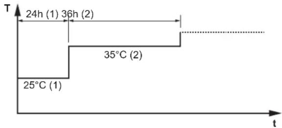
line
| Time | Temperature (°C) | | :--- | :--- | | 0 | 25 | | 1 | 24 | | 2 | 35 | | 3 | 36 | | 4 | 35 | The chart displays a discrete thermal process with two distinct temperature levels at each interval. The x-axis represents time (t), and the y-axis represents temperature (T). The labels indicate the time points: '24h (1)' for the first interval and '36h (2)' for the second. The dotted line appears to represent a constant or reference temperature level.T Desired leaving water temperature (15\~55°C)
t Duration (1\~72 h)
(1) Action step
(2) Action step 2
Steps
| 1 | Set the user permission level to Installer. See "To change the user permission level" [▶ 117]. | — |
| 2 | Go to [A.4.2]: Commissioning >UFH screed dryout > Program. | ### |
| 3 P | Program the schedule:To add a new step, select the next empty line and change its value. To delete a step and all steps below it, decrease the duration to “—”. | — |
| • Scroll through the schedule. | ### | |
| • Adjust the duration (between 1 and 72 hours) and temperatures (between 15°C and 55°C). | ○...○ | |
| 4 P | Press the left dial to save the schedule. | ### |
To perform an underfloor heating screed dryout

INFORMATION
- If Emergency is set to Manual ([9.5]=0), and the unit is triggered to start emergency operation, the user interface will ask confirmation before starting. The underfloor heating screed dryout function is active even if the user does NOT confirm emergency operation.
During underfloor heating screed dryout, pump speed limitation [9-0D] is NOT applicable.

NOTICE
To perform an underfloor heating screed dryout, room frost protection needs to be disabled ([2-06]=0). By default, it is enabled ([2-06]=1). However, due to the "installer-on-site" mode (see "Commissioning"), room frost protection will be automatically disabled for 12 hours after the first power-on.
If the screed dryout still needs to be performed after the first 12 hours of power-on, manually disable room frost protection by setting [2-06] to "0", and KEEP it disabled until the screed dryout has finished. Ignoring this notice will result in cracking of the screed.

NOTICE
For the underfloor heating screed dryout to be able to start, make sure the following settings are met:
[4-00]=1
[C-02]=0
[D-01]=0
[4-08]=0
[4-01]≠1
Steps
Conditions: An underfloor heating screed dryout schedule has been programmed. See "To program an underfloor heating screed dryout schedule" [▶ 205].
Conditions: Make sure all operation is disabled. Go to [C]: Operation and turn off Room, Space heating/cooling and Tank operation.
| 1 | Set the user permission level to Installer. See "To change the user permission level" [▶ 117]. | — |
| 2 | Go to [A.4]: Commissioning >UFH screed dryout. | ###...○ |
| 3 | Select Start UFH screed dryout. | ###...○ |
| 4 | Select OK to confirm.Result: The underfloor heating screed dryout starts. It stops automatically when done. | |
| 5 | To stop the underfloor heating screed dryout manually: — | |
| 1 Open the menu and go to Stop UFH screed dryout. | ###...○ | |
| 2 Select OK to confirm. | ###...○ |
To read out the status of an underfloor heating screed dryout
Conditions: You are performing an underfloor heating screed dryout.
| 1 Press the back button.Result: A graph is displayed, highlighting the current step of the screed dryout schedule, the total remaining time, and the current desired leaving water temperature. | ← | |
| 2 Press the left dial to open the menu structure and to: | ### | |
| 1 View the status of sensors and actuators. — | ||
| 2 Adjust the current program — | ||
To stop an underfloor heating (UFH) screed dryout
U3-error
When the program is stopped by an error, an operation switch off, or a power failure, the U3 error will be displayed on the user interface. To resolve the error codes, see "13.4 Solving problems based on error codes" [▶ 224].
Stop UFH screed dryout
To manually stop underfloor heating screed dryout:
| 1 | Go to [A.4.3]: Commissioning >UFH screed dryout | — |
| 2 | Select Stop UFH screed dryout. | ###...○ |
| 3 | Select OK to confirm.Result:The underfloor heating screed dryout is stopped. | ###...○ |
Read out UFH screed dryout status
When the program is stopped due to an error, an operation switch-off, or a power failure, you can read out the underfloor heating screed dryout status:
| 1 | Go to [A.4.3]: Commissioning >UFH screed dryout >Status | |
| 2 | You can read out the value here: Stopped at + the step where the underfloor screed dryout was stopped. | — |
3 Modify and restart the execution of the program (a).
一
(a) If the UFH screed dryout program was stopped due to a power failure and the power resumes, the program will automatically restart the last implemented step.
11 Hand-over to the user
Once the test run is finished and the unit operates properly, please make sure the following is clear for the user:
- Fill in the installer setting table (in the operation manual) with the actual settings.
- Make sure that the user has the printed documentation and ask him/her to keep it for future reference. Inform the user that he can find the complete documentation at the URL mentioned earlier in this manual.
- Explain the user how to properly operate the system and what to do in case of problems.
- Show the user what to do for the maintenance of the unit.
- Explain the user about energy saving tips as described in the operation manual.
12 Maintenance and service

NOTICE
General maintenance/inspection checklist. Next to the maintenance instructions in this chapter, a general maintenance/inspection checklist is also available on the Daikin Business Portal (authentication required).
The general maintenance/inspection checklist is complementary to the instructions in this chapter and can be used as a guideline and reporting template during maintenance.

NOTICE
Maintenance MUST be done by an authorized installer or service agent.
We recommend performing maintenance at least once a year. However, applicable legislation might require shorter maintenance intervals.
In this chapter
12.1 Overview: Maintenance and service.... 210
12.2 Maintenance safety precautions.... 210
12.3 Yearly maintenance 211
12.3.1 Yearly maintenance outdoor unit: overview 211
12.3.2 Yearly maintenance outdoor unit: instructions.... 211
12.3.3 Yearly maintenance indoor unit: overview 211
12.3.4 Yearly maintenance indoor unit: instructions 211
12.4 To drain the domestic hot water tank 214
12.5 About cleaning the water filter in case of trouble 214
12.5.1 To remove the water filter 215
12.5.2 To clean the water filter in case of trouble 215
12.5.3 To install the water filter 216
12.1 Overview: Maintenance and service
This chapter contains information about:
- The yearly maintenance of the outdoor unit
■ The yearly maintenance of the indoor unit
12.2 Maintenance safety precautions

DANGER: RISK OF ELECTROCUTION

DANGER: RISK OF BURNING

NOTICE: Risk of electrostatic discharge
Before performing any maintenance or service work, touch a metal part of the unit in order to eliminate static electricity and to protect the PCB.
12.3 Yearly maintenance
12.3.1 Yearly maintenance outdoor unit: overview
Check the following at least once a year:
- Heat exchanger
Water filter
12.3.2 Yearly maintenance outdoor unit: instructions
Heat exchanger
The heat exchanger of the outdoor unit can get blocked up due to dust, dirt, leaves, etc. It is recommended to clean the heat exchanger yearly. A blocked heat exchanger can lead to too low pressure or too high pressure leading to worse performance.
Water filter
Clean and rinse the water filter.

NOTICE
Handle the filter with care. To prevent damage to the mesh of the filter, do NOT use excessive force when you reinsert it.
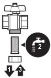
12.3.3 Yearly maintenance indoor unit: overview
- Water pressure
■ Magnetic filter/dirt separator
■ Water pressure relief valve - Relief valve hose
- Pressure relief valve of the domestic hot water tank
- Switch box
- Descaling
- Chemical disinfection
12.3.4 Yearly maintenance indoor unit: instructions
Water pressure
Keep water pressure above 1 bar. If it is lower, add water.
Magnetic filter/dirt separator
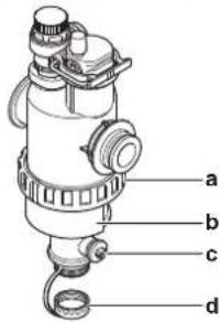
a Screw connection
b Magnetic sleeve
c Drain valve
d Drain cap
The yearly maintenance of the magnetic filter/dirt separator consists of:
- Checking if both parts of the magnetic filter/dirt separator are still screwed tight (a).
- Emptying the dirt separator as follows:
1 Take off the magnetic sleeve (b).
2 Unscrew the drain cap (d).
3 Connect a drain hose to the bottom of the water filter so that the water and dirt can be collected in a suitable container (bottle, sink...).
4 Open the drain valve for a couple of seconds (c).
Result: Water and dirt will come out.
5 Close the drain valve.
6 Screw the drain cap back on.
7 Reattach the magnetic sleeve.
8 Check the pressure of the water circuit. If required, add water.

NOTICE
- When checking the magnetic filter/dirt separator for tightness, hold it firmly, so as NOT to apply stress to the water piping.
- Do NOT isolate the magnetic filter/dirt separator by closing the shut-off valves. To properly empty the dirt separator, sufficient pressure is required.
- To prevent dirt from remaining in the dirt separator, ALWAYS take off the magnetic sleeve.
- ALWAYS first unscrew the drain cap, and connect a drain hose to the bottom of the water filter, then open the drain valve.

INFORMATION
For yearly maintenance, you do not have to remove the water filter from the unit to clean it. But in case of trouble with the water filter, you might have to remove it so that you can thoroughly clean it. Then you need to do as follows:
- "12.5.1 To remove the water filter" [▶ 215]
- "12.5.2 To clean the water filter in case of trouble" [▶ 215]
- "12.5.3 To install the water filter" [▶ 216]
Water pressure relief valve
Open the valve and check if it operates correctly. The water may be very hot!
Checkpoints are:
- The water flow coming from the relief valve is high enough, no blockage of the valve or in between piping is suspected.
- Dirty water coming out of the relief valve:
- open the valve until the discharged water does NOT contain dirt anymore
- flush the system
It is recommended to do this maintenance more frequently.
Pressure relief valve hose
Check whether the pressure relief valve hose is positioned appropriately to drain the water. See "6.4.4 To connect the drain hose to the drain" [▶ 72].
Pressure relief valve of the domestic hot water tank (field supply)
Open the valve.

CAUTION
Water coming out of the valve may be very hot.
- Check if nothing blocks the water in the valve or in between piping. The water flow coming from the relief valve must be high enough.
- Check if the water coming out of the relief valve is clean. If it contains debris or dirt:
- Open the valve until the discharged water does not contain debris or dirt anymore.
- Flush and clean the complete tank, including the piping between the relief valve and cold water inlet.
To make sure this water originates from the tank, check after a tank heat up cycle.

INFORMATION
It is recommended to perform this maintenance more than once a year.
Switch box
- Carry out a thorough visual inspection of the switch box and look for obvious defects such as loose connections or defective wiring.
- Using an ohmmeter, check if contactors K1M, K2M, K3M and K5M (depending on your installation) operate correctly. All contacts of these contactors must be in open position when the power is turned OFF.

WARNING
If the internal wiring is damaged, it has to be replaced by the manufacturer, its service agent or similarly qualified persons.
Descaling
Depending on water quality and set temperature, scale can deposit on the heat exchanger inside the domestic hot water tank and can restrict heat transfer. For this reason, descaling of the heat exchanger may be required at certain intervals.
Chemical disinfection
If the applicable legislation requires a chemical disinfection in specific situations, involving the domestic hot water tank, please be aware that the domestic hot water tank is a stainless steel cylinder. We recommend to use a non-chloride based disinfectant approved for use with water intended for human consumption.

NOTICE
When using means for descaling or chemical disinfection, it must be ensured that the water quality remains compliant with EU directive 98/83 EC.
12.4 To drain the domestic hot water tank

DANGER: RISK OF BURNING
The water in the tank can be very hot.
Prerequisite: Stop the unit operation via the user interface.
Prerequisite: Turn OFF the respective circuit breaker.
Prerequisite: Close the cold water supply.
Prerequisite: Open all the hot water tapping points to allow air to enter the system.
1 Remove the top panel, the user interface panel and the front panel.
2 Lower the switch box.
3 Remove the stop from the access point to the tank.
4 Use a drain hose and a pump to drain the tank via the access point.
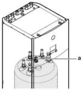
a Access point to the tank
12.5 About cleaning the water filter in case of trouble

INFORMATION
For yearly maintenance, you do not have to remove the water filter from the unit to clean it. But in case of trouble with the water filter, you might have to remove it so that you can thoroughly clean it. Then you need to do as follows:
- "12.5.1 To remove the water filter" [▶ 215]
"12.5.2 To clean the water filter in case of trouble" [▶ 215] - "12.5.3 To install the water filter" [▶ 216]
12.5.1 To remove the water filter
Prerequisite: Stop the unit operation via the user interface.
Prerequisite: Turn OFF the respective circuit breaker.
1 The water filter is located behind the switch box. To get access to it, see:
- "6.2.5 To open the indoor unit" [▶ 61]
- "6.2.6 To lower the switch box on the indoor unit" [▶ 63]
2 Close the stop valves of the water circuit.
3 Close the valve (if equipped) of the water circuit towards the expansion vessel.
4 Remove the cap on the bottom of the magnetic filter/dirt separator.
5 Connect a drain hose to the bottom of the water filter.
6 Open the valve on the bottom of the water filter to drain water from the water circuit. Collect the drained water in a bottle, sink,... using the installed drain hose.
7 Remove the 2 clips that fix the water filter.
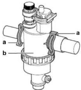
a Clip
b Magnetic filter/dirt separator
8 Remove the water filter.
9 Remove the drain hose from the water filter.

CAUTION
Although the water circuit is drained, some water may be spilled when removing the magnetic filter/dirt separator from the filter housing. ALWAYS clean up spilled water.
12.5.2 To clean the water filter in case of trouble
1 Remove the water filter from the unit. See "12.5.1 To remove the water filter" [▶ 215].

CAUTION
To protect the piping connected to the magnetic filter/dirt separator from damage it is recommended to perform this procedure with the magnetic filter/dirt separator removed from the unit.
2 Unscrew the bottom of the water filter housing. Use an appropriate tool if needed.

CAUTION
Opening the magnetic filter/dirt separator is ONLY required in case of severe issues. Preferably this action is never to be done during the complete lifetime of the magnetic filter/dirt separator.
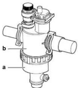
a Bottom part to be unscrewed b Water filter housing
3 Remove the strainer and the rolled-up filter from the water filter housing and clean with water.
4 Install the cleaned rolled-up filter and strainer in the water filter housing.

INFORMATION
Correctly install the strainer in the magnetic filter/dirt separator housing using the protrusions.
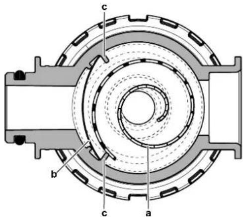
a Rolled-up filter
b Strainer
c Protrusion
5 Install and properly tighten the bottom of the water filter housing.
12.5.3 To install the water filter

CAUTION
Check the condition of the O-rings and replace if needed. Apply water to the O-rings before installation.
1 Install the water filter in the correct location.
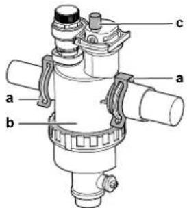
a Clip b Magnetic filter/dirt separator
c Air purge valve
2 Install the 2 clips to fix the water filter to the water circuit pipes.
3 Make sure that the air purge valve of the water filter is in the open position.
4 Open the valve (if equipped) of the water circuit towards the expansion vessel.

CAUTION
Make sure to open the valve (if equipped) towards the expansion vessel, otherwise the overpressure will be generated.
5 Open the stop valves and add water to the water circuit if needed.
13 Troubleshooting
Contact
For the symptoms listed below, you can try to solve the problem yourself. For any other problem, contact your installer. You can find the contact/helpdesk number via the user interface.
1 Go to [8.3]: Information > Dealer information.
10...
In this chapter
13.1 Overview: Troubleshooting 218
13.2 Precautions when troubleshooting.... 218
13.3 Solving problems based on symptoms.... 219
13.3.1 Symptom: The unit is NOT heating or cooling as expected 219
13.3.2 Symptom: Hot water does NOT reach the desired temperature 220
13.3.3 Symptom: The compressor does NOT start (space heating or domestic water heating) 220
13.3.4 Symptom: The system is making gurgling noises after commissioning.... 220
13.3.5 Symptom: The pump is blocked.... 221
13.3.6 Symptom: The pump is making noise (cavitation) 221
13.3.7 Symptom: The pressure relief valve opens 222
13.3.8 Symptom: The water pressure relief valve leaks 222
13.3.9 Symptom: The space is NOT sufficiently heated at low outdoor temperatures 223
13.3.10 Symptom: The pressure at the tapping point is temporarily unusually high 224
13.3.11 Symptom: Tank disinfection function is NOT completed correctly (AH-error) 224
13.4 Solving problems based on error codes 224
13.4.1 To display the help text in case of a malfunction.... 224
13.4.2 Error codes: Overview 225
13.1 Overview: Troubleshooting
This chapter describes what you have to do in case of problems.
It contains information about:
- Solving problems based on symptoms
- Solving problems based on error codes
Before troubleshooting
Carry out a thorough visual inspection of the unit and look for obvious defects such as loose connections or defective wiring.
13.2 Precautions when troubleshooting

WARNING
- When carrying out an inspection on the switch box of the unit, ALWAYS make sure that the unit is disconnected from the mains. Turn off the respective circuit breaker.
- When a safety device was activated, stop the unit and find out why the safety device was activated before resetting it. NEVER shunt safety devices or change their values to a value other than the factory default setting. If you are unable to find the cause of the problem, call your dealer.

DANGER: RISK OF ELECTROCUTION

WARNING
Prevent hazards due to inadvertent resetting of the thermal cut-out: power to this appliance MUST NOT be supplied through an external switching device, such as a timer, or connected to a circuit that is regularly turned ON and OFF by the utility.

DANGER: RISK OF BURNING
13.3 Solving problems based on symptoms
13.3.1 Symptom: The unit is NOT heating or cooling as expected
| Possible causes Corrective action | |
| The temperature setting is NOT correct Check and make sure that:All shut-off valves of the water circuit are completely open.The water filter is clean. Clean if necessary.There is no air in the system. Purge air if necessary. You can purge air manually (see "To perform a manual air purge" [▶ 202]) or use the automatic air purge function (see "To perform an automatic air purge" [▶ 203]).The water pressure is >1 bar.The expansion vessel is NOT broken.The valve (if equipped) of the water circuit towards the expansion vessel is open.The resistance in the water circuit is NOT too high for the pump (see the ESP curve in the "Technical data" chapter).If the problem persists after you have conducted all of the above checks, contact your dealer. In some cases, it is normal that the unit decides to use a low water flow. | |
| The water flow is too low Check and make sure that:All shut-off valves of the water circuit are completely open.The water filter is clean. Clean if necessary.There is no air in the system. Purge air if necessary. You can purge air manually (see "To perform a manual air purge" [▶ 202]) or use the automatic air purge function (see "To perform an automatic air purge" [▶ 203]).The water pressure is >1 bar.The expansion vessel is NOT broken. The valve (if equipped) of the water circuit towards the expansion vessel is open.The resistance in the water circuit is NOT too high for the pump (see the ESP curve in the "Technical data" chapter).If the problem persists after you have conducted all of the above checks, contact your dealer. In some cases, it is normal that the unit decides to use a low water flow. | |
| The water volume in the installation is too low | Make sure that the water volume in the installation is above the minimum required value (see "7.1.3 To check the water volume and flow rate" [▶ 76]). |
13.3.2 Symptom: Hot water does NOT reach the desired temperature
| Possible causes Corrective action | |
| One of the tank temperature sensors is broken. | See the service manual of the unit for the corresponding corrective action. |
13.3.3 Symptom: The compressor does NOT start (space heating or domestic water heating)
| Possible causes Corrective action | |
| The compressor cannot start if the water temperature is too low. The unit will use the backup heater to reach the minimum water temperature (12°C), after which the compressor can start. | If the backup heater doesn't start either, check and make sure that: ·The power supply to the backup heater is correctly wired. ·The backup heater thermal protector is NOT activated. ·The backup heater contactors are NOT broken.If the problem persists, contact your dealer. |
| The preferential kWh rate power supply settings and electrical connections do NOT match | This should match with the connections as explained in: ·"8.3.1 To connect the main power supply" [▶ 102] ·"8.1.4 About preferential kWh rate power supply" [▶ 90] ·"8.1.5 Overview of electrical connections except external actuators" [▶ 91] |
| The preferential kWh rate signal was sent by the electricity company | In the user interface of the unit, go to [8.5.B] Information >Actuators > Forced off contact.If Forced off contact is On, the unit is operating under the preferential kWh rate. Wait for the power to return (maximum 2 hours). |
13.3.4 Symptom: The system is making gurgling noises after commissioning
| Possible cause Corrective action | |
| There is air in the system. Purge air from | the system. (a) |
| Various malfunctions. | Check if or is displayed on the home screen of the user interface. See "13.4.1 To display the help text in case of a malfunction" [▶ 224] for more information about the malfunction. |
(a) We recommend to purge air with the air purge function of the unit (to be performed by the installer). If you purge air from the heat emitters or collectors, mind the following:

WARNING
Air purging heat emitters or collectors. Before you purge air from heat emitters or collectors, check if or is displayed on the home screen of the user interface.
- If not, you can purge air immediately.
- If yes, make sure that the room where you want to purge air is sufficiently ventilated. Reason: Refrigerant might leak into the water circuit, and subsequently into the room when you purge air from the heat emitters or collectors.
13.3.5 Symptom: The pump is blocked
| Possible causes Corrective action | |
| If the unit has been powered off for a long time, lime might block the rotor of the pump. | Remove the screw of the stator housing and use a screwdriver to turn back and forth the ceramic shaft of the rotor until the rotor is deblocked.(a)Note: Do NOT use excessive force. |
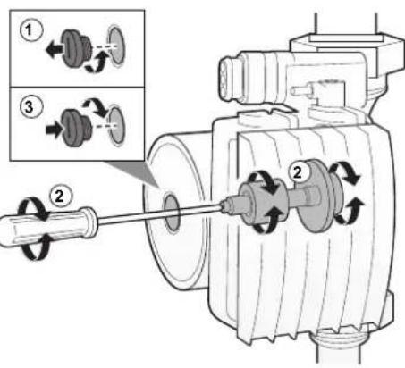 | |
(a) If you cannot deblock the rotor of the pump with this method, you will need to disassemble the pump and turn the rotor by hand.
13.3.6 Symptom: The pump is making noise (cavitation)
| Possible causes Corrective action | |
| There is air in the system Purge air manually (see "To perform a manual air purge" [▶ 202]) or use the automatic air purge function (see "To perform an automatic air purge" [▶ 203]). | |
| The water pressure at the pump inlet is too low | Check and make sure that:· The water pressure is >1 bar.· The water pressure sensor is not broken.· The expansion vessel is NOT broken.· The valve (if equipped) of the water circuit towards the expansion vessel is open.· The pre-pressure setting of the expansion vessel is correct (see "7.1.4 Changing the pre-pressure of the expansion vessel" [ ▶ 79]). |
13.3.7 Symptom: The pressure relief valve opens
| Possible causes Corrective action | |
| The expansion vessel is broken Replace the expansion vessel. | |
| The valve (if equipped) of the water circuit towards the expansion vessel is closed. | Open the valve. |
| The water volume in the installation is too high | Make sure that the water volume in the installation is below the maximum allowed value (see "7.1.3 To check the water volume and flow rate" [▶ 76] and "7.1.4 Changing the pre-pressure of the expansion vessel" [▶ 79]). |
| The water circuit head is too high The water circuit head is the difference in height between the indoor unit and the highest point of the water circuit. If the indoor unit is located at the highest point of the installation, the installation height is considered 0 m. The maximum water circuit head is 10 m.Check the installation requirements. | |
13.3.8 Symptom: The water pressure relief valve leaks
| Possible causes Corrective action | |
| Dirt is blocking the water pressure relief valve outlet | Check whether the pressure relief valve works correctly by turning the red knob on the valve counterclockwise:If you do NOT hear a clacking sound, contact your dealer.If the water keeps running out of the unit, close both the water inlet and outlet shut-off valves first and then contact your dealer. |
13.3.9 Symptom: The space is NOT sufficiently heated at low outdoor temperatures
| Possible causes Corrective action | |
| The backup heater operation is not activated | Check the following:· The backup heater operation mode is enabled.Go to: [9.3.8]: Installer settings > Backup heater > Operation [4-00]· The backup heater overcurrent circuit breaker is on. If not, turn it back on.· The thermal protector of the backup heater is NOT activated. If it has, check the following, and then press the reset button in the switch box:- The water pressure- Whether there is air in the system- The air purge operation |
| The backup heater equilibrium temperature has not been configured correctly | Increase the equilibrium temperature to activate the backup heater operation at a higher outdoor temperature.Go to: [9.3.7]: Installer settings > Backup heater > Equilibrium temperature [5-01] |
| There is air in the system. Purge air manually or automatically. See the air purge function in the chapter "10 Commissioning" [▶ 199]. | |
| Too much heat pump capacity is used for heating domestic hot water | Check if the Space heating priority settings have been configured appropriately:· Make sure that the Space heating priority has been enabled.Go to [9.6.1]: Installer settings > Balancing > Space heating priority [5-02]· Increase the "space heating priority temperature" to activate backup heater operation at a higher outdoor temperature.Go to [9.6.3]: Installer settings > Balancing > Priority temperature [5-03] |
13.3.10 Symptom: The pressure at the tapping point is temporarily unusually high
| Possible causes Corrective action | |
| Failing or blocked pressure relief valve. | Flush and clean the complete tank including the piping between pressure relief valve and the cold water inlet.Replace the pressure relief valve. |
13.3.11 Symptom: Tank disinfection function is NOT completed correctly (AH-error)
| Possible causes Corrective action | |
| The disinfection function was interrupted by domestic hot water tapping | Program the start-up of the disinfection function when the coming 4 hours NO domestic hot water tapping is expected. |
| Large domestic hot water tapping happened recently before the programmed start-up of the disinfection function | If in [5.6] Tank > Heat up mode the mode Reheat only or Schedule +reheat is selected, it is recommended to program the start-up of the disinfection function at least 4 hours later than the last expected large hot water tapping. This start-up can be set by installer settings (disinfection function).If in [5.6] Tank > Heat up mode the mode Schedule only is selected, it is recommended to program a Eco action 3 hours before the scheduled start-up of the disinfection function to preheat the tank. |
| The disinfection operation was stopped manually: [C.3] Operation >Tank was turned off during disinfection. | Do NOT stop tank operation during disinfection. |
13.4 Solving problems based on error codes
If the unit runs into a problem, the user interface displays an error code. It is important to understand the problem and to take measures before resetting an error code. This should be done by a licensed installer or by your local dealer.
This chapter gives you an overview of most possible error codes and their descriptions as they appear on the user interface.

INFORMATION
See the service manual for:
The complete list of error codes
- A more detailed troubleshooting guideline for each error
13.4.1 To display the help text in case of a malfunction
In case of a malfunction, the following will appear on the home screen depending on the severity:
:Error
- :Malfunction
You can get a short and a long description of the malfunction as follows:
| 1 Press the left dial to open the main menu and go to Malfunctioning.Result:A short description of the error and the error code is displayed on the screen. | ### |
| 2 Press in the error screen.Result:A long description of the error is displayed on the screen. | ? |
13.4.2 Error codes: Overview
Error codes of the unit
| Error code | Description | |
| 7H-01 | flow | low problem |
| 7H-04 | flow | low problem during domestic hot water production |
| 7H-05 | flow | low problem during heating/sampling |
| 7H-06 | flow | low problem during cooling/defrost |
| 80-01 | returning | water temperature sensor problem |
| 81-00 | leaving | water temperature sensor problem |
| 81-01 | mixed | water thermistor abnormality. |
| 81-06 | entering | water temperature thermistor abnormality (indoor unit) |
| 89-01 | heat | changer frozen (during defrost) |
| 89-02 | heat | changer frozen (not during defrost) |
| 89-03 | heat | changer frozen (during defrost) |
| 8F-00 | Abnormal | increase outlet water temperature (DHW) |
| 8H-00 | Abnormal | increase outlet water temperature |
| 8H-01 | overheating | ing mixed water circuit |
| 8H-02 | overheating | ing mixed water circuit (thermostat) |
| 8H-03 | overheating | ing water circuit (thermostat) |
| A1-00 | Zero | cross detection problem |
| A5-00 | OU: | high pressure peak cut / freeze protection problem |
| AA-01 | Backup | heater overheated |
| AC-00 | Booster | heater overheated |
| AH-00 Tank | infection function not completed correctly | |
| AJ-03 Too | long | DHW heat-up time required |
| C0-00 Flow | sensor malfunction | |
| C4-00 Heat | changer temperature sensor problem | |
| C5-00 Heat | changer thermistor abnormality | |
| CJ-02 Room | temperature sensor problem | |
| E1-00 OU: | defect | |
| E2-00 Leakage | current detection error | |
| E3-00 OU: | Actuation of high pressure switch (HPS) | |
| E3-24 High | pressure switch abnormality | |
| E4-00 Abnormal | suction pressure | |
| E5-00 OU: | overheat of inverter compressor motor | |
| E6-00 OU: | compressor startup defect | |
| E7-00 OU: | Malfunction of outdoor unit fan motor | |
| E8-00 OU: | Power input overvoltage | |
| E9-00 Malfunction | ion of electronic expansion valve | |
| EA-00 OU: | Cool/heat switchover problem | |
| EC-00 Abnormal | increase tank temperature | |
| EC-04 Tank | preheating | |
| F3-00 OU: | Malfunction of discharge pipe temperature | |
| F6-00 OU: | Abnormal high pressure in cooling | |
| FA-00 OU: | Abnormal high pressure, actuation of HPS | |
| H0-00 OU: | Voltage/current sensor problem | |
| H1-00 External | temperature sensor problem | |
| H3-00 OU: | Malfunction of high pressure switch (HPS) | |
| H4-00 Malfunction | ion of low pressure switch | |
| H5-00 Malfunction | ion of compressor overload protection | |
| H6-00 OU: | Malfunction of position detection sensor | |
| H8-00 OU: | Malfunction of compressor input (CT) system | |
| H9-00 OU: | Malfunction of outdoor air thermistor | |
| HC-00 Tank | temperature sensor problem | |
| HC-01 Second Tank | tank temperature sensor problem | |
| HJ-10 Water pressure sensor abnormality | ||
| J3-00 OU: | Malfunction of discharge pipe thermistor | |
| J3-10 Compressor port thermistor abnormality | ||
| J5-00 Malfunction of suction pipe thermistor | ||
| J6-00 OU: | Malfunction of heat exchanger thermistor | |
| J6-07 OU: | Malfunction of heat exchanger thermistor | |
| J6-32 Leaving water temperature thermistor Abnormality (outdoor unit) | ||
| J6-33 Sensor communication error | ||
| J8-00 Malfunction of refrigerant liquid thermistor | ||
| JA-00 OU: | Malfunction of high pressure sensor | |
| JC-00 Low pressure sensor abnormality | ||
| JC-01 Evaporator pressure abnormality | ||
| L1-00 Malfunction of INV PCB | ||
| L3-00 OU: | Electrical box temperature rise problem | |
| L4-00 OU: | Malfunction of inverter radiating fin temperature rise | |
| L5-00 OU: | Inverter instantaneous overcurrent (DC) | |
| L8-00 Malfunction triggered by a thermal protection in the inverter PCB | ||
| L9-00 Prevention of compressor lock | ||
| LC-00 Malfunction in communication system of outdoor unit | ||
| P1-00 Open-phase power supply imbalance | ||
| P3-00 Abnormal direct current | ||
| P4-00 OU: | Malfunction of radiating fin temperature sensor | |
| PJ-00 Capacity setting mismatch | ||
| U0-00 OU: | Shortage of refrigerant | |
| U1-00 Malfunction by reverse phase/open-phase | ||
| U2-00 OU: | Defect of power supply voltage | |
| U3-00 Underfloor heating screed dryout function not completed correctly | ||
| U4-00 Indoor/outdoor unit communication problem | ||
| U5-00 User interface communication problem | ||
| U7-00 OU: | smission malfunction between main CPU-INV CPU | |
| U8-01 Connection | on with LAN adapter lost | |
| U8-02 Connection | on with room thermostat lost | |
| U8-03 No Connection | ction with room thermostat | |
| U8-04 Unknown | USB device | |
| U8-05 File Malfunction | ||
| U8-07 P1P2 Communication error | ||
| UA-00 Indoor unit, outdoor unit matching problem | ||
| UA-16 Extension/hydro communication problem | ||
| UA-17 Tank type problem | ||
| UA-21 Extension/hydro mismatch problem | ||
| UF-00 Reversed piping or bad communication wiring detection | ||

INFORMATION
In case of error code AH and no interruption of the disinfection function occurred due to domestic hot water tapping, following actions are recommended:
- When the Reheat only or Schedule + reheat mode is selected, it is recommended to program the start-up of the disinfection function at least 4 hours later than the last expected large hot water tapping. This start-up can be set by installer settings (disinfection function).
- When the Schedule only mode is selected, it is recommended to program an Eco action 3 hours before the scheduled start-up of the disinfection function to preheat the tank.

NOTICE
When the minimum water flow is lower than described in the table below, the unit will temporarily stop operation and the user interface will display error 7H-01. After some time, this error will reset automatically and the unit will resume operation.
Minimum required flow rate
25 l/min

INFORMATION
Error AJ-03 is reset automatically from the moment there is a normal tank heat-up.

INFORMATION
If an U8-04 error occurs, the error can be reset after a successful update of the software. If the software is not successfully updated then you must make sure that your USB device has the FAT32 format.

INFORMATION
The user interface of the indoor unit will display how to reset an error code.
14 Disposal

NOTICE
Do NOT try to dismantle the system yourself: dismantling of the system, treatment of the refrigerant, oil and other parts MUST comply with applicable legislation. Units MUST be treated at a specialised treatment facility for reuse, recycling and recovery.
In this chapter
14.1 To recover refrigerant 229
14.1 To recover refrigerant
When disposing of the outdoor unit, you need to recover its refrigerant.
- Use the service port (a) to recover refrigerant.
- Make sure the valves (Y1E, Y3E, Y2S, Y3S, Y4S) are open. If they are not open during refrigerant recovery, refrigerant remains trapped in the unit.
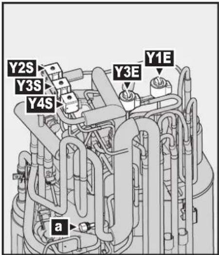
a Service port 5/16" flare
Y1E Electronic expansion valve (main)
Y3E Electronic expansion valve (injection)
Y2S Solenoid valve (low pressure bypass)
Y3S Solenoid valve (hot gas bypass)
Y4S Solenoid valve (liquid injection)
To open the valves when power is ON

WARNING
Rotating fan. Before powering ON or servicing the outdoor unit, make sure that the discharge grille covers the fan as protection against a rotating fan. See:
- "6.3.6 To install the discharge grille" [▶ 68]
- "6.3.7 To remove the discharge grille, and put the grille in safety position" [▶ 69]
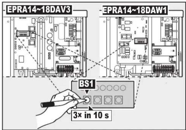
a Push button
1 Make sure the unit is not running.
2 Activate the vacuum/recovery mode by pushing BS1 3 times within 10 seconds. To push BS1, use an insulated stick (such as a closed ballpoint pen) to prevent touching of live parts.
Result: The unit opens all necessary valves.
3 After recovering refrigerant, deactivate the vacuum/recovery mode by pushing BS1 3 times within 10 seconds.
To open the valves when power is OFF
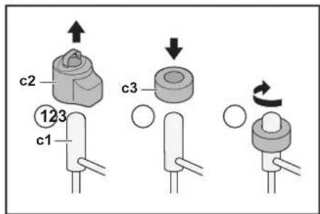
c1 Electronic expansion valve / Solenoid valve
c2 EEV coil
c3 EEV magnet
1 Remove the EEV coil (c2).
2 Slide an EEV magnet (c3) over the expansion valve / solenoid valve (c1).
3 Turn the EEV magnet clockwise to the fully open position of the valve. If you are not sure about what the open position is, turn the valve in its middle position so that refrigerant can pass.
15 Technical data
A subset of the latest technical data is available on the regional Daikin website (publicly accessible). The full set of latest technical data is available on the Daikin Business Portal (authentication required).
In this chapter
15.1 Service space: Outdoor unit 232
15.2 Piping diagram: Outdoor unit 233
15.3 Piping diagram: Indoor unit 234
15.4 Wiring diagram: Outdoor unit 235
15.5 Wiring diagram: Indoor unit 240
15.1 Service space: Outdoor unit
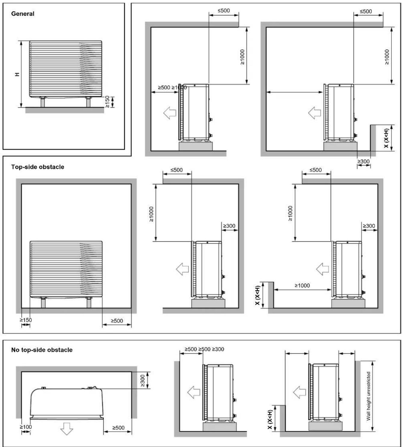
(mm) 3D124412
| English Translation | |
| General General | |
| No top-side obstacle No top-side obstacle | |
| Top-side obstacle Top-side obstacle | |
| Wall height unrestricted Wall height unrestricted |
15.2 Piping diagram: Outdoor unit
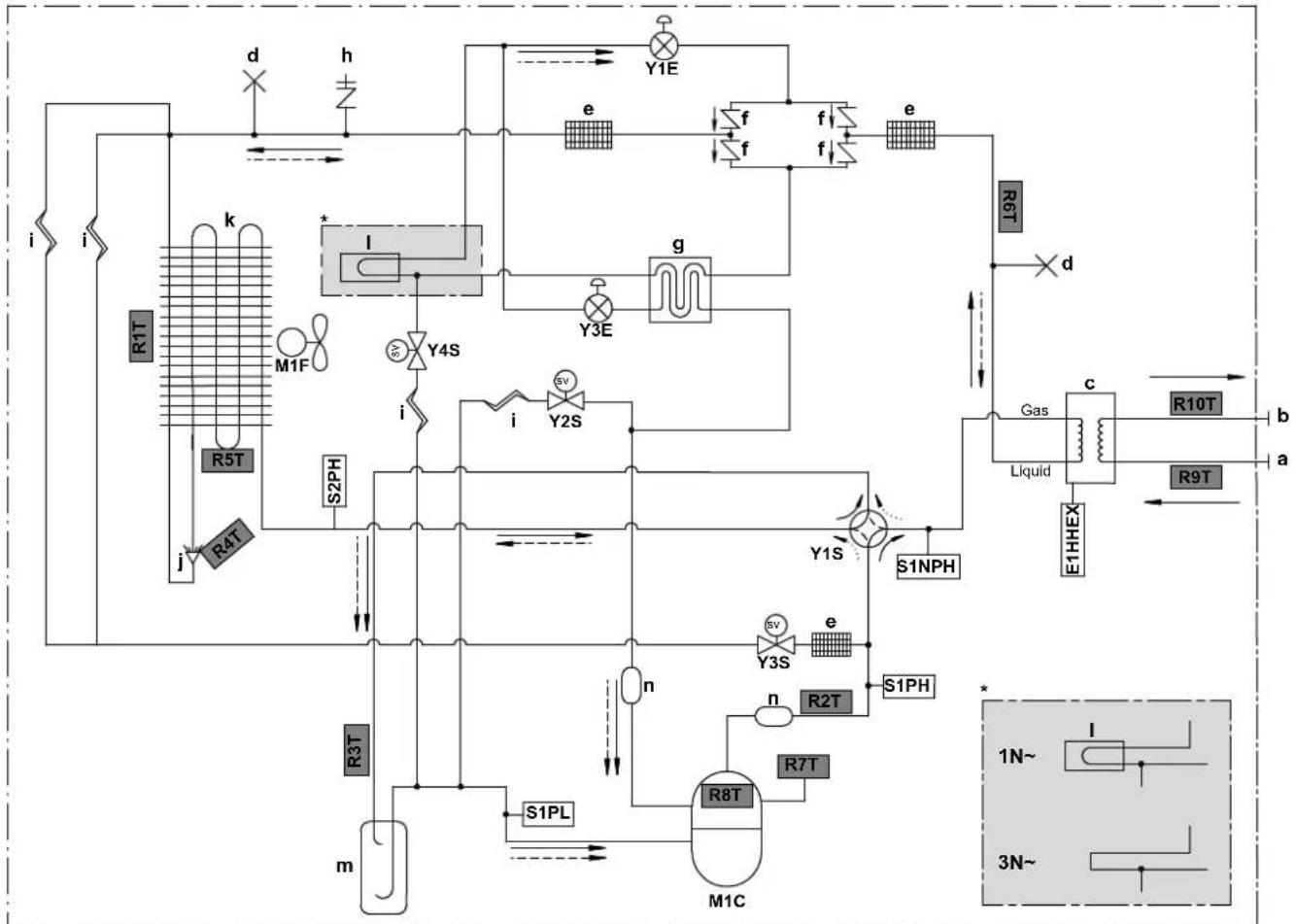
flowchart
graph TD
    A["i"] --> B["R1T"]
    B --> C["k"]
    C --> D["M1F"]
    D --> E["R5T"]
    E --> F["j"]
    F --> G["R4T"]
    G --> H["S2PH"]
    H --> I["i"]
    I --> J["Y4S"]
    J --> K["SV"]
    K --> L["Y2S"]
    L --> M["i"]
    M --> N["Y3E"]
    N --> O["g"]
    O --> P["Y1E"]
    P --> Q["e"]
    Q --> R["f"]
    R --> S["f"]
    S --> T["e"]
    T --> U["R6T"]
    U --> V["d"]
    V --> W["Gas"]
    W --> X["Liquid"]
    X --> Y["E1HHEX"]
    Y --> Z["R9T"]
    Z --> AA["b"]
    AA --> AB["a"]
    AB --> AC["S1NPH"]
    AC --> AD["Y1S"]
    AD --> AE["S1PH"]
    AE --> AF["e"]
    AF --> AG["R2T"]
    AG --> AH["n"]
    AH --> AI["R7T"]
    AI --> AJ["R8T"]
    AJ --> AK["M1C"]
    AK --> AL["S1PL"]
    AL --> AM["m"]
    AM --> AN["r3T"]
    AN --> AO["S2PH"]
    AO --> AP["i"]
    AP --> AQ["Y4S"]
    AQ --> AR["y2S"]
    AR --> AS["S1NPH"]
    AS --> AT["e"]
    AT --> AU["R2T"]
    AU --> AV["n"]
    AV --> AW["R7T"]
    AW --> AX["R8T"]
    AX --> AY["M1C"]
    AY --> AZ["S1PL"]
    AZ --> BA["m"]
    BA --> BB["r3T"]
    BB --> BC["S2PH"]
    BC --> BD["i"]
    BD --> BE["Y4S"]
    BE --> BF["y2S"]
    BF --> BG["S1NPH"]
    BG --> BH["e"]
    BH --> BI["R2T"]
    BI --> BJ["n"]
    BJ --> BK["R7T"]
    BK --> BL["R8T"]
    BL --> BM["M1C"]
    BM --> BN["r3T"]
    BN --> BO["S2PH"]
    BO --> BP["i"]
    BP --> BQ["Y4S"]
    BQ --> BR["y2S"]
    BR --> BS["S1NPH"]
3D124079C
Gas Gas Thermistors:
Liquid Liquid R1T Outdoor air
a Water IN (screw connection, male, 1") R2T Compressor discharge
b Water OUT (screw connection, male, 1") R3T Compressor suction
c Plate heat exchanger R4T Air heat exchanger, distributor
d Pinched pipe R5T Air heat exchanger, middle
e Refrigerant filter R6T Refrigerant liquid
f One-way valve R7T Compressor shell
g Economiser heat exchanger R8T Compressor port
h Service port 5/16" flare R9T Entering water
i Capillary tube R10T Leaving water
j Distributor
k Air heat exchanger Refrigerant flow:
I PCB cooling Heating
m Accumulator
n Muffler
E1HHEX Plate heat exchanger heater
M1C Compressor
M1F Fan motor
S1PH High pressure switch (5.6 MPa)
S2PH High pressure switch (4.17 MPa)
S1PL Low pressure switch
S1NPH High pressure sensor
Y1E Electronic expansion valve (main)
Y3E Electronic expansion valve (injection)
Y1S Solenoid valve (4-way valve)
Y2S Solenoid valve (low pressure bypass)
Y3S Solenoid valve (hot gas bypass)
Y4S Solenoid valve (liquid injection)
15.3 Piping diagram: Indoor unit
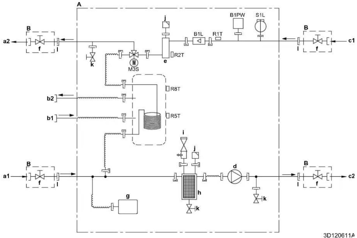
flowchart
graph TD
    A["Terminal a"] --> B["Terminal b1"]
    A --> C["Terminal b2"]
    A --> D["Terminal c1"]
    A --> E["Terminal c2"]

    subgraph Section A
        B --> f1["f"]
        f1 --> I1["I"]
        I1 --> J1["k"]
        J1 --> M["M3S"]
        M --> e["e"]
        e --> R2["T"]
        R2 --> B1L["B1L"]
        R1L --> R1T["R1T"]
        R1T --> S1L["S1L"]
        S1L --> B1PW["B1PW"]
        S1L --> S1Lw["S1L"]
    end

    subgraph Section B
        B1 --> f2["f"]
        f2 --> I2["I"]
        I2 --> g["g"]
        g --> h["h"]
        h --> d["d"]
        d --> k["k"]
        k --> h
        h --> i["i"]
        i --> j["j"]
    end

    subgraph Section C
        B2 --> f3["f"]
        f3 --> I3["I"]
        I3 --> g
        g --> h
        h --> d
        d --> k
        k --> h
        h --> i
        i --> j
        j --> h
        h --> d
        d --> k
    end

    subgraph Section C1
        B3 --> f4["f"]
        f4 --> I4["I"]
        I4 --> g
        g --> h
        h --> i
        i --> j
        j --> h
        h --> d
        d --> k
    end

    style Section A fill:#f9f,stroke:#333
    style Section B fill:#ccf,stroke:#333
    style Section C fill:#cfc,stroke:#333
A Indoor unit
B Field installed
a1 Space heating water IN
a2 Space heating water OUT
b1 Domestic hot water: cold water IN, loose nut 3/4"
b2 Domestic hot water: hot water OUT, loose nut 3/4"
c1 Water IN connection
c2 Water OUT connection
d Pump
e Backup heater
1 Shut-off valve, male-female 1"
g Expansion vessel
h Magnetic filter/dirt separator
i Safety valve
j Air purge
k Drain valve
I Loose nut 1"
B1L Flow sensor
B1PW Space heating water pressure sensor
M3S 3-way valve (space heating/domestic hot water)
R1T Thermistor (water IN)
R2T Thermistor (backup heater – water OUT)
R5T, R8T Thermistor (tank)
S1L Flow switch

Screw connection
Flare connection
Quick coupling

Brazed connection
15.4 Wiring diagram: Outdoor unit
The wiring diagram is delivered with the unit, located at the inside of the switch box cover.
| English Translation | |
| Electronic component assembly Electronic component assembly | |
| Front side view Front side view | |
| Indoor Indoor | |
| OFF OFF | |
| ON ON | |
| Outdoor Outdoor | |
| Position of compressor terminal Position of compressor terminal | |
| Position of elements Position of elements | |
| Rear side view (only for W1 models) | Rear side view |
| Right side view Right side view | |
| See note *** See note *** | |
Notes:
| 1 Symbols: | |
| L Live | |
| N | Neutral |
| Protective earth | |
| Noiseless earth | |
| Field wiring | |
| == | Option |
| Terminal strip | |
| Terminal | |
| Connector | |
| Connection | |
| 2 Colours: | |
| BLK Black | |
| RED Red | |
| BLU Blue | |
| WHT White | |
| GRN Green | |
| YLW Yellow | |
| PNK Pink | |
| ORG Orange | |
| GRY Grey | |
| BRN Brown | |
| 3 This wiring diagram applies only to the outdoor unit. | |
| 4 When operating, do not short-circuit protective devices S1PH, S2PH and S1PL. | |
| 5 Refer to the combination table and the option manual for how to connect the wiring to X6A, X41A and X2M. | |
| 6 The factory setting of all switches is OFF, do not change the setting of the selector switch (DS1). | |
| 7 (only for W1 models)Ferrite core Z8C consists of 2 separate core parts. | |
Legend in case of V3 models:
| A1P Printed circuit board (main) | |
| A2P Printed circuit board (noise filter) | |
| A3P Printed circuit board (leakage current) | |
| A4P Printed circuit board (ACS) | |
| A5P Printed circuit board (flash) | |
| BS1~BS4 (A1P) Push button switch | |
| C1~C4 (A1P, A2P) Capacitor | |
| DS1 (A1P) DIP switch | |
| E1H Drain tube heater (field supply) | |
| E1HHEX~E3HHEX Plate heat exchanger heaters | |
| F1U Field fuse (field supply) | |
| F1U~F4U (A2P) Fuse | |
| F6U (A1P) Fuse (T 5.0 A / 250 V) | |
| H1P~H7P (A1P) | Light-emitting diode (service monitor is orange) |
| HAP (A1P) | Light-emitting diode (service monitor is green) |
| K1R (A1P) | Magnetic relay (Y1S) |
| K1R (A4P) | Magnetic relay (E1HHEX~E3HHEX) |
| K2R (A1P) | Magnetic relay (Y2S) |
| K2R (A4P) Magnetic relay (E1H) | |
| K3R (A1P) Magnetic relay (Y3S) | |
| K4R (A1P) Magnetic relay (E1HC) | |
| K10R (A1P) Magnetic relay | |
| K11M (A1P) Magnetic contactor | |
| K13R~K15R (A1P, A2P) Magnetic relay | |
| L1R~L3R (A1P) Reactor | |
| M1C Compressor motor | |
| M1F Fan motor | |
| PS (A1P) Switching power supply | |
| Q1DI Earth leakage circuit breaker (30 mA) (field supply) | |
| R1~R5 (A1P, A2P) Resistor | |
| R1T Thermistor (outdoor air) | |
| R2T Thermistor (compressor discharge) | |
| R3T Thermistor (compressor suction) | |
| R4T Thermistor (air heat exchanger, distributor) | |
| R5T Thermistor (air heat exchanger, middle) | |
| R6T Thermistor (refrigerant liquid) | |
| R7T Thermistor (compressor shell) | |
| R8T Thermistor (compressor port) | |
| R9T Thermistor (entering water) | |
| R10T Thermistor (leaving water) | |
| R11T Thermistor (fin) | |
| RC (A2P) Signal receiver circuit | |
| S1NPH High pressure sensor | |
| S1PH, S2PH High pressure switch | |
| S1PL Low pressure switch | |
| T1A Current transfo | |
| TC (A2P) Signal transmission circuit | |
| V1D~V4D (A1P) | Diode |
| V1R (A1P) | IGBT power module |
| V2R (A1P) | Diode module |
| V1T~V3T (A1P) | Insulated Gate Bipolar Transistor (IGBT) |
| X1M, X2M | Terminal strip |
| Y1E | Electronic expansion valve (main) |
| Y3E | Electronic expansion valve (injection) |
| Y1S | Solenoid valve (4-way valve) |
| Y2S | Solenoid valve (low pressure bypass) |
| Y3S Solenoid valve (hot gas bypass) |
| Y4S Solenoid valve (liquid injection) |
| Z1C~Z11C Noise filter (ferrite core) |
| Z1F~Z6F (A1P, A2P) Noise filter |
Legend in case of W1 models:
| A1P Printed circuit board (main) | |
| A2P Printed circuit board (noise filter) | |
| A3P Printed circuit board (leakage current) | |
| A4P Printed circuit board (ACS) | |
| A5P Printed circuit board (inverter) | |
| BS1~BS4 (A1P) Push button switch | |
| C1~C3 (A2P) Capacitor | |
| DS1 (A1P) DIP switch | |
| E1H Drain tube heater (field supply) | |
| E1HHEX Plate heat exchanger heater | |
| F1U Field fuse (field supply) | |
| F1U~F7U (A1P, A2P) Fuse | |
| H1P~H7P (A1P) Light-emitting diode (service monitor is orange) | |
| HAP (A1P, A2P) Light-emitting diode (service monitor is green) | |
| K1R (A1P) Magnetic relay (Y1S) | |
| K1R (A2P) Magnetic relay | |
| K1R (A4P) Magnetic relay (E1HHEX) | |
| K2R (A1P) Magnetic relay (Y2S) | |
| K2R (A4P) Magnetic relay (E1H) | |
| K3R (A1P) Magnetic relay (Y3S) | |
| K4R (A1P) Magnetic relay (E1HC) | |
| K2M, K11M (A2P) Magnetic contactor | |
| L1R~L4R Reactor | |
| M1C Compressor motor | |
| M1F | Fan motor |
| PS (A2P) | Switching power supply |
| Q1DI | Earth leakage circuit breaker (30 mA) (field supply) |
| R1, R2 (A2P) | Resistor |
| R1T | Thermistor (outdoor air) |
| R2T | Thermistor (compressor discharge) |
| R3T | Thermistor (compressor suction) |
| R4T | Thermistor (air heat exchanger, distributor) |
| R5T | Thermistor (air heat exchanger, middle) |
| R6T Thermistor (refrigerant liquid) |
| R7T Thermistor (compressor shell) |
| R8T Thermistor (compressor port) |
| R9T Thermistor (entering water) |
| R10T Thermistor (leaving water) |
| R11T Thermistor (fin) |
| S1NPH High pressure sensor |
| S1PH, S2PH High pressure switch |
| S1PL Low pressure switch |
| T1A Current transfo |
| V1R, V2R (A2P) IGBT power module |
| V3R (A2P) Diode module |
| X1M, X2M Terminal strip |
| Y1E Electronic expansion valve (main) |
| Y3E Electronic expansion valve (injection) |
| Y1S Solenoid valve (4-way valve) |
| Y2S Solenoid valve (low pressure bypass) |
| Y3S Solenoid valve (hot gas bypass) |
| Y4S Solenoid valve (liquid injection) |
| Z1C~Z10C Noise filter (ferrite core) |
| Z1F~Z4F (A1P, A3P) Noise filter |
15.5 Wiring diagram: Indoor unit
See the internal wiring diagram supplied with the unit (on the inside of the indoor unit switch box cover). The abbreviations used are listed below.
Notes to go through before starting the unit
| English Translation | |
| Notes to go through before starting the unit | Notes to go through before starting the unit |
| X1M Main terminal | |
| X2M Field wiring terminal for AC | |
| X5M Field wiring terminal for DC | |
| X6M Backup heater power supply terminal | |
| ---- | Earth wiring |
| ---- | Field supply |
| 1 | Several wiring possibilities |
| Option | |
| Not mounted in switch box | |
| Wiring depending on model | |
| PCB | |
| Note 1: Connection point of the power supply for the BUH should be foreseen outside the unit. | Note 1: Connection point of the power supply for the backup heater should be foreseen outside the unit. |
| Backup heater power supply Backup heater power supply | |
| ☐6T1 (3~, 230 V, 6 kW) 6T1 (3~, 230 V, 6 kW) | |
| ☐6V (1N~, 230 V, 6 kW) 6V (1N~, 230 V, 6 kW) | |
| ☐6WN/9WN (3N~, 400 V, 6/9 kW) 6WN/9WN (3N~, 400 V, 6/9 kW) | |
| User installed options User installed options | |
| ☐LAN adapter LAN adapter | ☐ |
| ☐WLAN adapter WLAN adapter | ☐ |
| ☐Remote user interface Dedicated Human Comfort Interface(BRC1HHDA used as room thermostat) | |
| ☐Ext. indoor thermistor External indoor thermistor | |
| ☐Ext outdoor thermistor External outdoor thermistor | |
| ☐Digital I/O PCB Digital I/O PCB | ☐ |
| ☐Demand PCB Demand PCB | ☐ |
| ☐Safety thermostat | ☐Safety thermostat |
| Main LWT | Main leaving water temperature |
| ☐On/OFF thermostat (wired) | ☐On/OFF thermostat (wired) |
| ☐On/OFF thermostat (wireless) | ☐On/OFF thermostat (wireless) |
| ☐Ext. thermistor | ☐External thermistor |
| □ Heat pump convector Heat pump convector | |
| Add LWT Additional leaving water temperature | |
| □ On/OFF thermostat (wired) On/OFF thermostat (wired) | |
| □ On/OFF thermostat (wireless) On/OFF thermostat (wireless) | |
| □ Ext. thermistor External thermistor | □ |
| □ Heat pump convector Heat pump convector | |
Position in switch box
| English Translation | |
| Position in switch box Position in switch box | |
| SWB1 Upper switch box | |
| SWB2 Lower switch box |
Legend
| A1P Main PCB | ||
| A2P * On/OFF thermostat (PC=power circuit) | ||
| A3P * Heat pump convector | ||
| A4P * Digital I/O PCB | ||
| A8P * Demand PCB | ||
| A11P MMI (= user interface of the indoor unit) – Main PCB | ||
| A13P * LAN adapter | ||
| A14P * PCB of the dedicated Human Comfort Interface(BRC1HHDA used as room thermostat) | ||
| A15P * Receiver PCB (wireless On/OFF thermostat) | ||
| A20P * WLAN adapter | ||
| CN* (A4P) * Connector | ||
| DS1(A8P) * DIP switch | ||
| F1B # Overcurrent fuse backup heater | ||
| F1U, F2U (A4P) | * Fuse 5 A 250 V for digital I/O PCB | |
| K1M, K2M | Contactor backup heater | |
| K5M | Safety contactor backup heater | |
| K*R (A4P) | Relay on PCB | |
| M2P | # Domestic hot water pump | |
| M2S # 2-way valve for cooling mode | ||
| PC (A15P) | * Power circuit | |
| PHC1 (A4P) | * Optocoupler input circuit | |
| Q1L Thermal protector backup heater | ||
| Q4L # Safety thermostat | ||
| Q*DI | # Earth leakage circuit breaker | |
| R1H (A2P) * Humidity sensor | ||
| R1T (A2P) * Ambient sensor | On/OFF thermostat | |
| R2T (A2P) * External sensor | (floor or ambient) | |
| R6T * External indoor or outdoor ambient thermistor | ||
| S1S # Preferential kWh rate | power supply contact | |
| S2S # Electricity meter pulse input 1 | ||
| S3S # Electricity meter pulse input 2 | ||
| S6S~S9S * Digital power limitation inputs | ||
| SS1 (A4P) * Selector switch | ||
| TR1 Power supply transformer | ||
| X6M # Backup heater power supply terminal strip | ||
| X*, X*A, X*Y, Y* Connector | ||
| X*M Terminal strip | ||
* Optional
Field supply
Translation of text on wiring diagram
| English Translation | |
| (1) Main power connection (1) Main power connection | |
| For preferential kWh rate power supply F | For preferential kWh rate power supply |
| Indoor unit supplied from outdoor Indoor | unit supplied from outdoor |
| Normal kWh rate power supply | Normal kWh rate power supply |
| Only for normal power supply (standard) | Only for normal power supply (standard) |
| Only for preferential kWh rate power supply (outdoor) | Only for preferential kWh rate power supply (outdoor) |
| Outdoor unit | Outdoor unit |
| Preferential kWh rate power supply contact: 16 V DC detection (voltage supplied by PCB) | Preferential kWh rate power supply contact: 16 V DC detection (voltage supplied by PCB) |
| SWB1 | Switch box |
| Use normal kWh rate power supply for indoor unit | Use normal kWh rate power supply for indoor unit |
| (2) Backup heater power supply | (2) Backup heater power supply |
| Only for *** | Only for *** |
| (3) User interface (3) User interface | |
| Only for LAN adapter | Only for the LAN adapter |
| Only for remote user interface HCI | Only for the dedicated Human Comfort Interface (BRC1HHDA used as room thermostat) |
| Only for WLAN adapter | Only for WLAN adapter |
| SWB1 | Switch box |
| (5) Ext. thermistor (5) External thermistor | |
| SWB1 Switch box | |
| (6) Field supplied options (6) Field supplied options | |
| 12 V DC pulse detection (voltage supplied by PCB) | 12 V DC pulse detection (voltage supplied by PCB) |
| 230 V AC supplied by PCB 230 V AC supplied by PCB | |
| Continuous Continuous current | |
| DHW pump output Domestic hot water pump output | |
| DHW pump Domestic hot water pump | |
| Electrical meters Electricity meters | |
| For safety thermostat For safety thermostat | |
| Inrush Inrush current | |
| Max. load Maximum load | |
| Normally closed Normally closed | |
| Normally open Normally open | |
| Safety thermostat contact: 16 V DC detection (voltage supplied by PCB) | Safety thermostat contact: 16 V DC detection (voltage supplied by PCB) |
| Shut-off valve Shut-off valve | |
| SWB1 Switch box | |
| (7) Option PCBs (7) Option PCBs | |
| Alarm output | Alarm output |
| Changeover to ext. heat source | Changeover to external heat source |
| Max. load Maximum load | |
| Min. load Minimum load | |
| Only for demand PCB option | Only for demand PCB option |
| Only for digital I/O PCB option | Only for digital I/O PCB option |
| Options: ext. heat source output, alarm output | Options: external heat source output, alarm output |
| Options: On/OFF output | Options: On/OFF output |
| Power limitation digital inputs: 12 V DC / 12 mA detection (voltage supplied by PCB) | Power limitation digital inputs: 12 V DC / 12 mA detection (voltage supplied by PCB) |
| Space C/H On/OFF output | Space cooling/heating On/OFF output |
| SWB | Switch box |
| (8) External On/OFF thermostats and heat pump convector | (8) External On/OFF thermostats and heat pump convector |
| Additional LWT zone | Additional leaving water temperature zone |
| Main LWT zone | Main leaving water temperature zone |
| Only for external sensor (floor/ambient) | Only for external sensor (floor or ambient) |
| Only for heat pump convector Only for heat pump convector | |
| Only for wired On/OFF thermostat Only for wired On/OFF thermostat | |
| Only for wireless On/OFF thermostat Only for wireless On/OFF thermostat | |
Electrical connection diagram
For more details, please check the unit wiring.
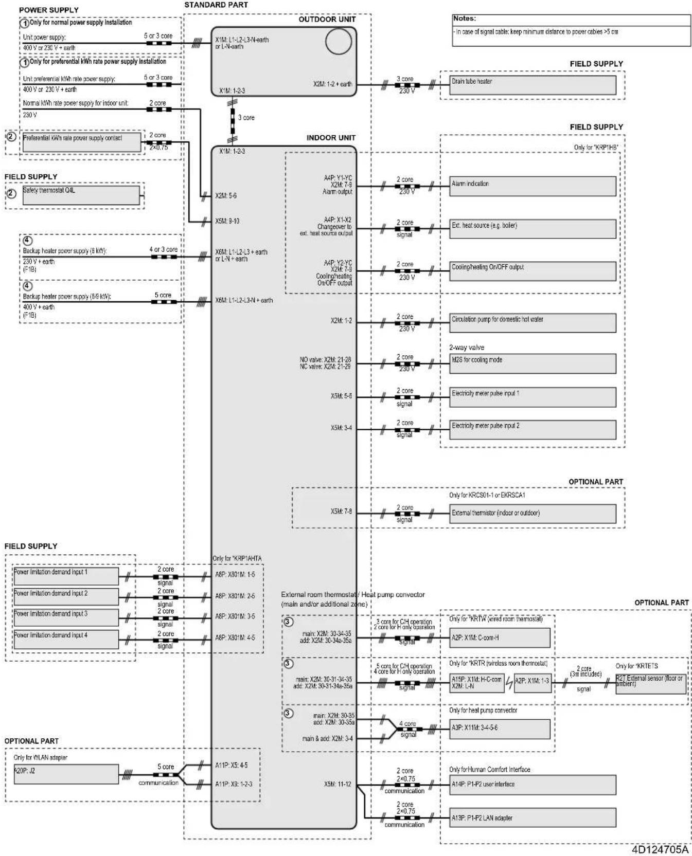
flowchart
graph TD
    A["POWER SUPPLY"] --> B["STANDARD PART"]
    B --> C["OUTDOOR UNIT"]
    C --> D["INDOOR UNIT"]
    D --> E["FIELD SUPPLY"]
    E --> F["OPTIONAL PART"]

    subgraph STANDARD PART
        G["1 Only for normal power supply installation"] --> H["X1M: L1-L2-L3-N-earth or L-N-earth"]
        I["2 Only for preferential kWh rate power supply installation"] --> J["X1M: 1-2-3"]
        K["3 Core"] --> L["X2M: 1-2 + earth"]
        M["4 Backup heater power supply (5 kV): 4 or 3 core"] --> N["X6M: L1-L2-L3 + earth or L-N + earth"]
        O["5 Core"] --> P["X6M: L1-L2-L3-N + earth"]
    end

    subgraph INDOOR UNIT
        Q["A4P: Y1-YC X2M: T-9 Alarm output"] --> R["A4P: X1-X2 Changeover to est. heat source output"]
        S["A4P: Y2-YC X2M: T-9 Coolingheating On/OFF output"] --> T["A4P: Y2-YC X2M: T-9 Coolingheating On/OFF output"]
        U["X2M: 1-2"] --> V["X2M: 1-2"]
        W["NO valve: X2M: 21-28 NC valve: X2M: 21-28"] --> X["X5M: 5-5"]
        Y["X5M: 3-4"] --> Z["X5M: 3-4"]
        AA["2 core"] --> AB["2 core"]
        AC["2 core"] --> AD["2 core"]
        AE["2 core"] --> AF["2 core"]
        AG["Circulation pump for domestic hot water"] --> AH["2-way valve"]
        AI["M2S for cooling mode"] --> AJ["Electricity meter pulse input 1"]
        AK["Electricity meter pulse input 2"] --> AL["Electricity meter pulse input 2"]
    end

    subgraph OPTIONAL PART
        AM["X5M: T-8"] --> AN["2 core signal"]
        AO["Only for KRCS01-1 or EKRSCA1"] --> AP["External thermistor (indoor or outdoor)"]
    end

    subgraph FIELD SUPPLY
        AQ["Power limitation demand input 1"] --> AR["2 core signal"]
        AS["Power limitation demand input 2"] --> AT["2 core signal"]
        AU["Power limitation demand input 3"] --> AV["2 core signal"]
        AW["Power limitation demand input 4"] --> AX["2 core signal"]
    end

    subgraph OPTIONAL PART
        AY["X1P: X5: 4-5"] --> AZ["A11P: X8: 1-2-3"]
    end

    subgraph OPTIONAL PART
        BA["X3M: 11-12"] --> BB["A11P: X8: 1-2-3"]
    end

    C --> BC["A4P: Y1-YC X2M: T-9 Alarm output"]
    D --> BD["A4P: X1-X2 Changeover to est. heat source output"]
    D --> BE["A4P: Y2-YC X2M: T-9 Coolingheating On/OFF output"]
    E --> BF["Alarm indication"]
    E --> BG["Ext. heat source (e.g. boiler)"]
    E --> BH["Cooling/heating On/CFF output"]
    AF --> BI["Special"]
    AG --> BJ["Special"]
    AH --> BK["Special"]
    AI --> BL["Special"]
    AJ --> BM["Special"]
    AK --> BN["Special"]
    AL --> BO["Special"]
    AM --> BP["X301M: 1-5"]
    AN --> BZ["X301M: 2-5"]
    AO --> CA["X301M: 3-5"]
    AP --> CB["X301M: 4-5"]
    AQ --> CC["X301M: 30-34-35 add: X30-34e-35a"]
    AR["X301M: 30-34e-35a"] --> AS["X301M: 30-34e-35a"]
    AT["X301M: 30-34e-35a add: X30-34e-35a"] --> AU["X301M: 30-34e-35a"]
    AV["X301M: 30-34e-35a add: X30-34e-35a"] --> AW["X301M: 30-34e-35a"]
    AX["X301M: 30-34e-35a add: X30-34e-35a"] --> AY["X301M: 30-34e-35a add: X30-34e-35a"]
    AZ["X301M: 30-34e-35a add: X30-34e-35a"] --> BA["X301M: 30-34e-35a add: X30-34e-35a"]
    BB["X301M: 30-34e-35a add: X30-34e-35a"] --> BC["X301M: 30-34e-35a add: X30-34e-35a"]
    BD["X301M: 30-34e-35a add: X30-34e-35a"] --> BDX["X301M: 1-5"]
    BE["X301M: 1-5"] --> BF["X301M: 2-5"]
    BF["X301M: 2-5"] --> BG["X301M: 2-5"]
    BH["X301M: 2-5"] --> BHX["X301M: 2-5"]
    BI["X301M: 2-5"] --> BJ["X301M: 2-5"]
    BK["X301M: 2-5"] --> BKX["X301M: 2-5"]
    BL["X301M: 2-5"] --> BLX["X301M: 2-5"]
    BN["X301M: 2-5"] --> BNX["X301M: 2-5"]
    BO["X301M: 2-5"] --> BOX["X301M: 2-5"]
    BP["X301M: 2-5"] --> BPX["X301M: 2-5"]
    BQ["X6M: L1-L2-L3-N earth or L-N-earth"] --> BR["X6M: L1-L2-L3-N earth or L-N-earth"]
    BS["X6M: L1-L2-L4-N earth or L-N-earth"] --> BT["X6M: L1-L2-L4-N earth or L-N-earth"]
16 Glossary
Dealer
Sales distributor for the product.
Authorised installer
Technical skilled person who is qualified to install the product.
User
Person who is owner of the product and/or operates the product.
Applicable legislation
All international, European, national and local directives, laws, regulations and/or codes that are relevant and applicable for a certain product or domain.
Service company
Qualified company which can perform or coordinate the required service to the product.
Installation manual
Instruction manual specified for a certain product or application, explaining how to install, configure and maintain it.
Operation manual
Instruction manual specified for a certain product or application, explaining how to operate it.
Maintenance instructions
Instruction manual specified for a certain product or application, which explains (if relevant) how to install, configure, operate and/or maintain the product or application.
Accessories
Labels, manuals, information sheets and equipment that are delivered with the product and that need to be installed according to the instructions in the accompanying documentation.
Optional equipment
Equipment made or approved by Daikin that can be combined with the product according to the instructions in the accompanying documentation.
Field supply
Equipment NOT made by Daikin that can be combined with the product according to the instructions in the accompanying documentation.
Applicable indoor units
ETBH16DA6V
ETBH16DA9W
ETBX16DA6V
ETBX16DA9W
ETVH16S18DA6V*
ETVH16S23DA6V*
ETVH16S18DA9W*
ETVH16S23DA9W*
ETVX16S18DA6V*
ETVX16S23DA6V*
ETVX16S18DA9W*
ETVX16S23DA9W*
Notes
(*1)*6V
(*2)*9W
(*3) ETB*
(*4) ETV*
(*5)*X*
(*6)*H*
| Field settings table | Installier setting at variance with default value | ||||
| Broadcrumb Field code Setting name Range, step | Default value | Date | Official Value | ||
| RoomAntifrost | |||||
| 1.4.1 [2-06] R/W 0: Disabled Activation | 1: Enabled | ||||
| 1.4.2 [2-05] R/W 4~16°C, step On/Setpoint | 8°C | ||||
| — Setpoint range | |||||
| 1.5.1 [3-07] R/W 12~18°C, step heating minimum | 12°C | ||||
| 1.5.2 [3-06] R/W 18~30°C, step heating maximum | 30°C | ||||
| 1.5.3 [3-09] R/W 15~25°C, step cooling maximum | 15°C | ||||
| 1.5.4 [3-08] R/W 25~35°C, step cooling maximum | 35°C | ||||
| Room | |||||
| 1.6 [2-09] R/W -5~5°C, step Random sensor offset | 0°C | ||||
| 1.7 [2-0A] R/W -5~5°C, step Random sensor offset | 0°C | ||||
| Main zone | |||||
| 2.4.0: Fixed | Setpoint mode | 1: WD heating, fixed cooling2: Weather dependent | |||
| Heating WD curve | |||||
| 2.5 [1-00] R/W -40~5°C, step Low Ambient temp. for LWT main zone heating WD curve. | -15°C | ||||
| 2.5 [1-01] R/W 10~25°C, step High Ambient temp. for LWT main zone heating WD curve. | 15°C | ||||
| 2.5 [1-02] R/W | Leaving water value for low ambient temp. for LWT main zone heating WD curve. | [9-01]-[9-00], step: 1°C[2-0C]=035°C[2-0C]=145°C[2-0C]=265°C | |||
| 2.5 [1-03] R/W [9-01]-min(45%+40%+40%+40%+40%+40%+40%+40%+40%+40%+40%+40%+40%+40%+40%+40%+40%+40%+40%+40%+40%+40%+40%+40%+40%+40%+45°C | [2-0C]=025°C[2-0C]=135°C[2-0C]=235°C | ||||
| Cooling WD curve | |||||
| 2.6 [1-06] R/W 10~25°C, step Low Ambient temp. for LWT main zone cooling WD curve. | 20°C | ||||
| 2.6 [1-07] R/W | High ambient temp. for LWT main zone cooling WD curve. | 25~43°C, step: 1°C35°C | |||
| 2.6 [1-08] R/W [9-03]-[9-02] | Leaving water value for low ambient temp. for LWT main zone cooling WD curve. | 22°C | |||
| 2.6 [1-09] R/W [9-03]-[9-02] | Leaving water value for high ambient temp. for LWT main zone cooling WD curve. | [2-0C]=018°C[2-0C]=17°C[2-0C]=218°C | |||
| Main zone | |||||
| 2.7 [2-0C] R/W | Emitter type | 0: Underfloor heating1: Fancoil unit2: Radiator | |||
| — Setpoint range | |||||
| 2.8.1 [9-01] R/W 15~37°C, step heating minimum | 25°C | ||||
| 2.8.2 [9-00] R/W [2-0C]=2: | Heating maximum | 37~70, step: 1°C70°C[2-0C]=2:37~55, step: 1°C55°C | |||
| 2.8.3 [9-03] R/W 5~18°C, step cooling minimum | 7°C | ||||
| 2.8.4 [9-02] R/W 18~22°C, step cooling maximum | 22°C | ||||
| Main zone | |||||
| 2.9 [C-07] R/W | Control | 0: LWT control1: Ext RT control2: RT control | |||
| 2.A [C-05] R/W 0:- | Thermostat type | 1: 1 contact2: 2 contacts | |||
| — Delta T | |||||
| 2.B.1 [1-0B] R/W 3~10°C, step Malta Cheating | 5°C | ||||
| 2.B.2 [1-0D] R/W 3~10°C, step Malta Cooling | 5°C | ||||
| — Modulation | |||||
| 2.C.1 [8-05] R/W | Modulation | 0: No1: Yes | |||
| 2.C.2 [8-06] R/W 0~10°C, step Oxid Co#dulation | 5°C | ||||
| — Shut off valve | |||||
| 2.D.1 [F-08] R/W | During thermo | 0: No1: Yes | |||
| 2.D.2 [F-0C] | During cooling | R/W 0: No | 1: Yes | ||
| Main zone | |||||
| 2.E | WD curve type | R/W 0: 2-points1: Slope-Offset | 1 | ||
| Additional zone | |||||
| 3.4.0: Fixed | Setpoint mode | 1: WD heating, fixed cooling2: Weather dependent | |||
(*1)*6V_(*2)*9W_
(*3) ETB* (*4) ETV*
(*5)*X*_(6)*H*
| Field settings table | Installier setting at variance with default value | ||||
| Breadcrumbs Field code Setting name Range, step | Default value | Date | Official Value | ||
| Heating WD curve | |||||
| 3.5 [0-00] R/W [9-05]-min(4-06) (stabilized) for high ambient temp. for LWT add zone heating WD curve. | [2-0C]=025°C[2-0C]=135°C[2-0C]=235°C | ||||
| 3.5 [0-01] R/W [9-05]-[9-06] (stabilized) for low ambient temp. for LWT add zone heating WD curve. | [2-0C]=035°C[2-0C]=145°C[2-0C]=265°C | ||||
| 3.5 [0-02] R/W 10-25°C, stethigh ambient temp. for LWT add zone heating WD curve. | 15°C | ||||
| 3.5 [0-03] R/W -40-5°C, stethigh ambient temp. for LWT add zone heating WD curve. | -15°C | ||||
| Cooling WD curve | |||||
| 3.6 [0-04] R/W [9-07]-[9-08] (stabilized) for high ambient temp. for LWT add zone cooling WD curve. | [2-0C]=018°C[2-0C]=17°C[2-0C]=218°C | ||||
| 3.6 [0-05] R/W [9-07]-[9-08] (stabilized) for low ambient temp. for LWT add zone cooling WD curve. | 22°C | ||||
| 3.6 [0-06] R/W 25-43°C, stethigh ambient temp. for LWT add zone cooling WD curve. | 35°C | ||||
| 3.6 [0-07] R/W 10-25°C, stethigh ambient temp. for LWT add zone cooling WD curve. | 20°C | ||||
| Additional zone | |||||
| 3.7 [2-0D] R/W 0: Underfloor heating type | 1: Fancoil unit2: Radiator | ||||
| Setpoint range | |||||
| 3.8.1 [9-05] R/W 15-37°C, stepping minimum | 25°C | ||||
| 3.8.2 [9-06] R/W [2-0D]=2: Heating maximum | 37-70, step: 1°C70°C[2-0D]=2;37-55, step: 1°C55°C | ||||
| 3.8.3 [9-07] R/W 5-18°C, stepping minimum | 7°C | ||||
| 3.8.4 [9-06] R/W 18-22°C, stepping maximum | 22°C | ||||
| Additional zone | |||||
| 3.A [C-06] R/W 0:- | Thermostat type | 1: 1 contact2: 2 contacts | |||
| Delta T | |||||
| 3.B.1 [1-0C] R/W 3-10°C, stepping Cheating | 10°C | ||||
| 3.B.2 [1-0E] R/W 3-10°C, stepping Cooling | 5°C | ||||
| Additional zone | |||||
| 3.C R/O 0: 2 points | WD curve type | 1: Slope-Offset | |||
| Space heating / cooling | |||||
| Operation range | |||||
| 4.3.1 [4-02] R/W 14-35°C, stepping Geating OFF temp | 35°C | ||||
| 4.3.2 [F-01] | Space cooling OFF temp R/W 10-35°C, step: 1°C20°C | ||||
| Space heating / cooling | |||||
| 4.4 [7-02] R/W | Number of zones | 0: 1 LWT zone1: 2 LWT zones | |||
| 4.5 [F-0D] | Pump operation mode R/W 0: Continuous | 1: Sample2: Request | |||
| 4.6 [E-02] R/W (*5) | Unit type | R/O (*6) | 0: Reversible (*5)1: Heating only (*6) | ||
| 4.7 [9-0D] R/W 0-8, step:1 | Pump limitation | 0: No limitation1-4:50-80%5-8:50-80% during sampling6 | |||
| Space heating / cooling | |||||
| 4.9 [F-00] | Pump outside range R/W | 0: Restricted1: Allowed | |||
| 4.A [D-03] R/W 0: No | Increase around 0°C | 1: Increase 2°C, span 4°C2: increase 4°C, span 4°C3: increase 2°C, span 8°C4: Increase 4°C, span 8°C | |||
| 4.B [9-04] R/W 1-4°C, step O/w shoot | 1°C | ||||
| 4.C [2-06] R/W 0: Additional | 1: Enabled | ||||
| Tank | |||||
| 5.2 [6-0A] R/W 30-(6-0E)*C (control setpoint) | 60°C | ||||
| 5.3 [6-0B] R/W 30-min(50, step Off/step: 1°C) | 45°C | ||||
| 5.4 [6-0C] R/W 30-min(50, step Off/step: 1°C) | 45°C | ||||
| 5.6 [6-0D] R/W 0: Reheat or heat up mode | 1: Reheat + sched.2: Scheduled only | ||||
(*1)*6V_(*2)*9W_
(*3) ETB* (*4) ETV*
(*5)*X*_(6)*H*
| Field settings table | Installer setting at variance with default value | |||||
| Breadcrumb Field code Setting name Range, step | Default value | Date | Official Value | |||
| Disinfection | ||||||
| 5.7.1 [2-01] R/W 0: No | Activation | 1: Yes | ||||
| 5.7.2 [2-00] R/W 0: Each day | Operation day | 1: Monday2: Tuesday3: Wednesday4: Thursday5: Friday6: Saturday7: Sunday | ||||
| 5.7.3 [2-02] R/W 0-23 hour | Slupt/1 hour | 1 | ||||
| 5.7.4 [2-03] R/W [E-07]# | Tank setpoint | 1:55~75°C, step: 5°C70°C[E-07]=1:60°C60°C | ||||
| 5.7.5 [2-04] R/W [E-07]#1: Separation, step: 5 min | 10 min[E-07]=1: 40~60 min, step: 5 min40 min | |||||
| Tank | ||||||
| 5.8 [6-0E] R/W (*3) [E-07]=0 Maximum | 40~75°C, step: 1°C60°C(*3) [E-07]=5:40~80°C, step: 1°C80°C(*4): 40~65°C, step: 1°C65°C | |||||
| 5.9 [6-00] R/W | Hysteresis | 2~40°C, step: 1°C8°C | ||||
| 5.A [6-08] R/W | Reheat hysteresis | 2~20°C, step: 1°C10°C | ||||
| 5.B R/W | Setpoint mode | 0: Fixed1: Weather dependent | ||||
| WD curve | ||||||
| 5.C [0-08] R/W 35~[6-0E]*C | Leasing Water value for high ambient temp. for DHW WD curve. | 55°C | ||||
| 5.C [0-0C] R/W 45~[6-0E]*C | Leasing Water value for low ambient temp. for DHW WD curve. | 60°C | ||||
| 5.C [0-0D] R/W 10~25°C, step: Ambient temp. for DHW WD curve. | 15°C | |||||
| 5.C [0-0E] R/W -40~5°C, step: Ambient temp. for DHW WD curve. | -10°C | |||||
| Tank | ||||||
| 5.D [6-01] R/W 0~10°C, step: Margin | 2°C | |||||
| 5.E R/O 0: 2-points | WD curve type | 1: Slope-Offset | ||||
| User settings | ||||||
| Quiet | ||||||
| 7.4.1 | Activation | R/W | 0: OFF1: Manual2: Automatic | |||
| 7.4.3 | Level | R/W | 0: Quiet1: More Quiet2: Most Quiet | |||
| Electricity price | ||||||
| 7.5.1 | High | R/W 0,00~990kWh1/kWh | ||||
| 7.5.2 | Medium | R/W 0,00~990kWh1/kWh | ||||
| 7.5.3 | Low | R/W 0,00~990kWh1/kWh | ||||
| User settings | ||||||
| 7.6 | Gas price | R/W 0,00~990kWh0,00~290/MBlu1,0/kWh | ||||
| installer settings | ||||||
| Configuration wizardSystem | ||||||
| 9.1.3.2 | E-03] R/O BUH type | 3: 6V (*1)4: 9W (*2) | ||||
| 9.1.3.3 | E-05][E-06][E-07]Domestic hot water | R/W | No DHW (*3)EKHW (*3)Integrated (*4)EKHWP (*3) | |||
| 9.1.3.4 | 4-06] R/W 0: Emergency | 1: Automatic2: Auto red SH/ DHW ON3: Auto red SH/ DHW OFF4: Auto normal SH/ DHW OFF | ||||
| 9.1.3.5 | 7-02] R/W Number of zones | 0: Single zone1: Dual zone | ||||
| 9.1.3.6 | E-0D] Glycol Filled system | R/W | 0: No1: Yes | |||
| 9.1.3.7 | 6-02] R/W 0-30kV capacity, 0.2kV | 3kW (*3)0kW (*4) | ||||
| Backup heater | ||||||
| 9.1.4.1 | 5-0D] R/W *Moltage | R/O (*2) | 0: 230V, 1~ (*1)1: 230V, 3~ (*1)2: 400V, 3~ (*2) | |||
| 9.1.4.2 | 4-0A] R/W Configuration | 0: 11: 1/1+2 (*1) (*2)2: 1/23: 1/2 + 1/1+2 in emergency | ||||
| 9.1.4.3 | 6-03] R/W 0-30kV step: 0.2kW | 2kW (*1)3kW (*2) | ||||
(*1)*6V_(*2)*9W_
(*3) ETB* (*4) ETV*
(*5)*X*_(6)*H*
| Field settings table | Installer setting at variance with default value | ||||
| Breadcrumbs Field code Setting name Range, step | Default value | Date | Official Value | ||
| 9.1.4.4 [6-04] R/W 0~10kW water level capacity step 2 | 4kW (*1)6kW (*2) | ||||
| Main zone | |||||
| 9.1.5.1 [2-0C] R/W | Emitter type | 0: Underfloor heating1: Fancoil unit2: Radiator | |||
| 9.1.5.2 [C-07] R/W | Control | 0: LWT control1: Ext RT control2: RT control | |||
| 9.1.5.3 R/W 0 Fixed | Setpoint mode | 1: WD heating, fixed cooling2: Weather dependent | |||
| 9.1.5.4 R/W | Schedule | 0: No1: Yes | |||
| 9.1.5.5 R/W 0 2-points | WD curve type | 1: Slope-Offset | |||
| 9.1.6 [1-00] R/W -40~5°C, step ambient temp. for LWT main zone heating WD curve. | -15°C | ||||
| 9.1.6 [1-01] R/W 10~25°C, step ambient temp. for LWT main zone heating WD curve. | 15°C | ||||
| 9.1.6 [1-02] R/W | Leaving water value for low ambient temp. for LWT main zone heating WD curve. | [9-01]-[9-00], step: 1°C[2-0C]=035°C[2-0C]=145°C[2-0C]=265°C | |||
| 9.1.6 [1-03] R/W [9-01]-min Leaving angle value for high ambient temp. for LWT main zone heating WD curve. | [2-0C]=025°C[2-0C]=135°C[2-0C]=235°C | ||||
| 9.1.7 [1-06] R/W 10~25°C, step ambient temp. for LWT main zone cooling WD curve. | 20°C | ||||
| 9.1.7 [1-07] R/W | High ambient temp. for LWT main zone cooling WD curve. | 25~43°C, step: 1°C35°C | |||
| 9.1.7 [1-08] R/W [9-03]-[9-02] Concentration value for low ambient temp. for LWT main zone cooling WD curve. | 22°C | ||||
| 9.1.7 [1-09] R/W [9-03]-[9-02] Concentration value for high ambient temp. for LWT main zone cooling WD curve. | [2-0C]=018°C[2-0C]=17°C[2-0C]=218°C | ||||
| Additional zone | |||||
| 9.1.8.1 [2-0D] R/W 0: Underfloor type | 1: Fancoil unit2: Radiator | ||||
| 9.1.8.3 R/W 0 Fixed | Setpoint mode | 1: WD heating, fixed cooling2: Weather dependent | |||
| 9.1.8.4 R/W | Schedule | 0: No1: Yes | |||
| 9.1.9 [0-00] R/W [9-05]-min Leaving temperature for high ambient temp. for LWT add zone heating WD curve. | [2-0C]=025°C[2-0C]=135°C[2-0C]=235°C | ||||
| 9.1.9 [0-01] R/W [9-05]-[9-02] Concentration value for low ambient temp. for LWT add zone heating WD curve. | [2-0C]=035°C[2-0C]=145°C[2-0C]=265°C | ||||
| 9.1.9 [0-02] R/W 10~25°C, step ambient temp. for LWT add zone heating WD curve. | 15°C | ||||
| 9.1.9 [0-03] R/W -40~5°C, step ambient temp. for LWT add zone heating WD curve. | -15°C | ||||
| 9.1.A [0-04] R/W [9-07]-[9-02] Concentration value for high ambient temp. for LWT add zone cooling WD curve. | [2-0C]=018°C[2-0C]=17°C[2-0C]=218°C | ||||
| 9.1.A [0-05] R/W [9-07]-[9-02] Concentration value for low ambient temp. for LWT add zone cooling WD curve. | 22°C | ||||
| 9.1.A [0-06] R/W 25~43°C, step ambient temp. for LWT add zone cooling WD curve. | 35°C | ||||
| 9.1.A [0-07] R/W 10~25°C, step ambient temp. for LWT add zone cooling WD curve. | 20°C | ||||
| Tank | |||||
| 9.1.B.1 [6-0D] R/W 0: Reheated up mode | 1: Reheat + sched.2: Scheduled only | ||||
| 9.1.B.2 [6-0A] R/W 30-[6-06] Concentration | 60°C | ||||
| 9.1.B.3 [6-05] R/W 30-min Concentration step: 1°C | 45°C | ||||
| 9.1.B.4 [6-0C] R/W 30-min Concentration step: 1°C | 45°C | ||||
| 9.1.B.5 [6-08] R/W Reheat hysteresis | 2~20°C, step: 1°C10°C | ||||
| Domestic hot water | |||||
(*1)*6V_(*2)*9W_
(*3) ETB*_(4) ETV*
(*5)*X*_(6)*H*
| Field settings table | Installier setting at variance with default value | |||||
| Breadcrumb Field code Setting name Range, step | Default value | Date | Official Value | |||
| 9.2.1 [E-05] | [E-06][E-07] | Domestic hot water | R/W | No DHW (*3)EKHW (*3)Integrated (*4)EKHWP (*3) | ||
| 9.2.2 [D-02] R/W | DHW pump | 0: No DHW pump1: Instant hot water2: Disinfection3: Circulation4: Circulation and disinfection | ||||
| 9.2.4 [D-07] R/W | Solar | 0: No1: Yes | ||||
| Back up heater | ||||||
| 9.3.1 [E-03] R/D | BUH type | 3: 6V (*1)4: 9W (*2) | ||||
| 9.3.2 [5-0D] R/W (*1) | Voltage | R/O (*2) | 0: 230V, 1~ (*1)1: 230V, 3~ (*1)2: 400V, 3~ (*2) | |||
| 9.3.3 [4-0A] R/W | Configuration | 1: 1/1+2 (*1) (*2)2: 1/23: 1/2 + 1/1+2 in emergency | ||||
| 9.3.4 [6-03] R/W 0~10kW, step-up 2nd Step 1 | 2kW (*1)3kW (*2) | |||||
| 9.3.5 [6-04] R/W 0~10kW, step-up 3rd Capacity step 2 | 4kW (*1)6kW (*2) | |||||
| 9.3.6 [5-00] R/W 0: Allowed Equilibrium | 1: Not allowed | |||||
| 9.3.7 [5-01] R/W -15~35°C, step-up 4th Temperature | 0°C | |||||
| 9.3.8 [4-00] R/W 0: Disabled Operation | 1: Enabled2: Only DHW | |||||
| Booster heater | ||||||
| 9.4.1 [6-02] R/W 0~10kW, step-up 2nd W | 3kW (*3)0kW (*4) | |||||
| 9.4.3 [8-03] R/W 20~95 min, BHP e-continmer | 50 min | |||||
| 9.4.4 [4-03] R/W 0: Restricted Operation | 1: Allowed2: Overlap3: Compressor off4: Legionella only | |||||
| Emergency | ||||||
| 9.5.1 [4-06] R/W 0: Manual Emergency | 1: Automatic2: Auto red SH/ DHW ON3: Auto red SH/ DHW OFF4: Auto normal SH/ DHW OFF | |||||
| 9.5.2 [7-06] R/W HP Forced OFF | 0: Disabled1: Enabled | |||||
| Balancing | ||||||
| 9.6.1 [5-02] R/W Space heating priority | 0: Disabled1: Enabled | |||||
| 9.6.2 [5-03] R/W -15~35°C, Security Temperature | 0°C | |||||
| 9.6.3 [5-04] R/W 0~20°C, stop-up CBSH setpoint | 10°C | |||||
| 9.6.4 [8-02] R/W 0~10 hour, step-up 5th Eauimer | 0,5 hour [E-07]=13 hour [E-07]*1 | |||||
| 9.6.5 [8-00] R/W Minimum running timer | 0~20 min, step 1 min1 min | |||||
| 9.6.6 [8-01] R/W 5~95 min, step-up 1m running timer | 30 min | |||||
| 9.6.7 [8-04] R/W 0~95 min, step-up 2m timer | 95 min | |||||
| Installer settings | ||||||
| 9.7 [4-04] R/O Water pipe freeze prevention | 0: Intermittent | |||||
| Benefit kWh power supply | ||||||
| 9.8.1 [D-01] R/W Benefit kWh power supply | 0: No1: Active open2: Active closed3: Safetythermostat | |||||
| 9.8.2 [D-00] R/W Allow heater | 0: None1: BSH only2: BUH only3: All heaters | |||||
| 9.8.3 [D-05] R/W 0: Forced offlow pump | 1: As normal | |||||
| Power consumption control | ||||||
| 9.9.1 [4-08] R/W Power consumption control | 0: No limitation1: Continuous2: Digital Inputs | |||||
| 9.9.2 [4-09] R/W 0: Current Type | 1: Power | |||||
| 9.9.3 [5-05] R/W 0~50 A, step-up/A | 50 A | |||||
| 9.9.4 [5-05] R/W 0~50 A, step-up/A | 50 A | |||||
| 9.9.5 [5-06] R/W 0~50 A, step-up/A | 50 A | |||||
| 9.9.6 [5-07] R/W 0~50 A, step-up/A | 50 A | |||||
| 9.9.7 [5-08] R/W 0~50 A, step-up/A | 50 A | |||||
| 9.9.8 [5-09] R/W 0~20 kW, step-up 0.5 kW | 20 kW | |||||
| 9.9.9 [5-09] R/W 0~20 kW, step-up 0.5 kW | 20 kW | |||||
| 9.9.A [5-0A] R/W 0~20 kW, step-up 2.5 kW | 20 kW | |||||
| Field settings table | Installer setting at variance with default value | ||||
| Breadcrumbs Field code Setting name Range, step | Default value | Date | Official Value | ||
| 9.9.B [5-08] R/W 0-20 kW, limit 8.5 kW | 20 kW | ||||
| 9.9.C [5-0C] R/W 0-20 kW, limit 4.5 kW | 20 kW | ||||
| 9.9.D [4-01] | Priority heater | 0: None1: BSH2: BUH | |||
| 9.9.F [7-07] R/W | BBR16 activation (#) | 0: Disabled1: Enabled | |||
| Energy metering | |||||
| 9.A.1 [D-08] R/W | Electricity meter 1 | 0: No1: 0.1 pulse/kWh2: 1 pulse/kWh3: 10 pulse/kWh4: 100 pulse/kWh5: 1000 pulse/kWh | |||
| 9.A.2 [D-09] R/W | Electricity meter 2 | 0: No1: 0.1 pulse/kWh2: 1 pulse/kWh3: 10 pulse/kWh4: 100 pulse/kWh5: 1000 pulse/kWh | |||
| Sensors | |||||
| 9.B.1 [C-08] R/W | External sensor | 0: No1: Outdoor sensor2: Room sensor | |||
| 9.B.2 [2-0B] R/W -5-5°C, step 0.5°C sensor offset | 0°C | ||||
| 9.B.3 [1-0A] R/W | Averaging time | 0: No averaging1: 12 hours2: 24 hours3: 48 hours4: 72 hours | |||
| Bivalent | |||||
| 9.C.1 [C-02] R/W | Bivalent | 0: No1: Bivalent | |||
| 9.C.2 [7-05] R/W | Boiler efficiency | 0: Very high1: High2: Medium3: Low4: Very low | |||
| 9.C.3 [C-03] R/W -25-25°C, step duration | 0°C | ||||
| 9.C.4 [C-04] R/W 2-10°C, step 1/2000 | 3°C | ||||
| Installer settings | |||||
| 9.D [C-09] R/W | Alarm output | 0: Normally open1: Normally closed | |||
| 9.E [3-00] R/W 0: No | Auto restart | 1: Yes | |||
| 9.F [E-08] R/W | Power saving function | 0: disabled1: Enabled | |||
| 9.G | Disable protections | R/W 0: No | 1: Yes | ||
| Overview field settings | |||||
| 9.I | [0-00] R/W [9-01] R/W [9-02] R/W [9-03] R/W [9-04] R/W [9-05] R/W [9-06] R/W [9-07] R/W [9-08] R/W [9-09] R/W [9-10] R/W [9-11] R/W [9-12] R/W [9-13] R/W [9-14] R/W [9-15] R/W [9-16] R/W [9-17] R/W [9-18] R/W [9-19] R/W [9-20] R/W [9-21] R/W [9-22] R/W [9-23] R/W [9-24] R/W [9-25] R/W [9-26] R/W [9-27] R/W [9-28] R/W [9-29] R/W [9-30] R/W [9-31] R/W [9-32] R/W [9-33] R/W [9-34] R/W [9-35] R/W [9-36] R/W [9-37] R/W [9-38] R/W [9-39] R/W [9-40] R/W [9-41] R/W [9-42] R/W [9-43] R/W [9-44] R/W [9-45] R/W [9-46] R/W [9-47] R/W [9-48] R/W [9-49] R/W [9-50] R/W [9-51] R/W [9-52] R/W [9-53] R/W [9-54] R/W [9-55] R/W [9-56] R/W [9-57] R/W [9-58] R/W [9-59] R/W [9-60] R/W [9-61] R/W [9-62] R/W [9-63] R/W [9-64] R/W [9-65] R/W [9-66] R/W [9-67] R/W [9-68] R/W [9-69] R/W [9-70] R/W [9-71] R/W [9-72] R/W [9-73] R/W [9-74] R/W [9-75] R/W [9-76] R/W [9-77] R/W [9-78] R/W [9-79] R/W [9-80] R/W [9-81] R/W [9-82] R/W [9-83] R/W [9-84] R/W [9-85] R/W [9-86] R/W [9-87] R/W [9-88] R/W [9-89] R/W [9-90] R/W [9-91] R/W [9-92] R/W [9-93] R/W [9-94] R/W [9-95] R/W [9-96] R/W [9-97] R/W [9-98] R/W [9-99] R/W [9-100] R/W [9-101] R/W [9-102] R/W [9-103] R/W [9-104] R/W [9-105] R/W [9-106] R/W [9-107] R/W [9-108] R/W [9-109] R/W [9-110] R/W [9-111] R/W [9-112] R/W [9-113] R/W [9-114] R/W [9-115] R/W [9-116] R/W [9-117] R/W [9-118] R/W [9-119] R/W [9-120] R/W [9-121] R/W [9-122] R/W [9-123] R/W [9-124] R/W [9-125] R/W [9-126] R/W [9-127] R/W [9-128] R/W [9-129] R/W [9-130] R/W [9-131] R/W [9-132] R/W [9-133] R/W [9-134] R/W [9-135] R/W [9-136] R/W [9-137] R/W [9-138] R/W [9-139] R/W [9-140] R/W [9-141] R/W [9-142] R/W [9-143] R/W [9-144] R/W [9-145] R/W [9-146] R/W [9-147] R/W [9-148] R/W [9-149] R/W [9-150] R/W [9-151] R/W [9-152] R/W [9-153] R/W [9-154] R/W [9-155] R/W [9-156] R/W [9-157] R/W [9-158] R/W [9-159] R/W [9-160] R/W [9-161] R/W [9-162] R/W [9-163] R/W [9-164] R/W [9-165] R/W [9-166] R/W [9-167] R/W [9-168] R/W [9-169] R/W [9-170] R/W [9-171] R/W [9-172] R/W [9-173] R/W [9-174] R/W [9-175] R/W [9-176] R/W [9-177] R/W [9-178] R/W [9-179] R/W [9-180] R/W [9-181] R/W [9-182] R/W [9-183] R/W [9-184] R/W [9-185] R/W [9-186] R/W [9-187] R/W [9-188] R/W [9-189] R/W [9-190] R/W [9-191] R/W [9-192] R/W [9-193] R/W [9-194] R/W [9-195] R/W [9-196] R/W [9-197] R/W [9-198] R/W [9-199] R/W [9-200] R/W [9-201] R/W [9-202] R/W [9-203] R/W [9-204] R/W [9-205] R/W [9-206] R/W [9-207] R/W [9-208] R/W [9-209] R/W [9-210] R/W [9-211] R/W [9-212] R/W [9-213] R/W [9-214] R/W [9-215] R/W [9-216] R/W [9-217] R/W [9-218] R/W [9-219] R/W [9-220] R/W [9-221] R/W [9-222] R/W [9-223] R/W [9-224] R/W [9-225] R/W [9-226] R/W [9-227] R/W [9-228] R/W [9-229] R/W [9-230] R/W [9-231] R/W [9-232] R/W [9-233] R/W [9-234] R/W [9-235] R/W [9-236] R/W [9-237] R/W [9-238] R/W [9-239] R/W [9-240] R/W [9-241] R/W [9-242] R/W [9-243] R/W [9-244] R/W [9-245] R/W [9-246] R/W [9-247] R/W [9-248] R/W [9-249] R/W [9-250] R/W [9-251] R/W [9-252] R/W [9-253] R/W [9-254] R/W [9-255] R/W [9-256] R/W [9-257] R/W [9-258] R/W [9-259] R/W [9-260] R/W [9-261] R/W [9-262] R/W [9-263] R/W [9-264] R/W [9-265] R/W [9-266] R/W [9-267] R/W [9-268] R/W [9-269] R/W [9-270] R/W [9-271] R/W [9-272] R/W [9-273] R/W [9-274] R/W [9-275] R/W [9-276] R/W [9-277] R/W [9-278] R/W [9-279] R/W [9-280] R/W [9-281] R/W [9-282] R/W [9-283] R/W [9-284] R/W [9-285] R/W [9-286] R/W [9-287] R/W [9-288] R/W [9-289] R/W [9-290] R/W [9-291] R/W [9-292] R/W [9-293] R/W [9-294] R/W [9-295] R/W [9-296] R/W [9-297] R/W [9-298] R/W [9-299] R/W [9-300] R/W [9-301] R/W [9-302] R/W [9-303] R/W [9-304] R/W [9-305] R/W [9-306] R/W [9-307] R/W [9-308] R/W [9-309] R/W [9-310] R/W [9-311] R/W [9-312] R/W [9-313] R/W [9-314] R/W [9-315] R/W [9-316] R/W [9-317] R/W [9-318] R/W [9-319] R/W [9-320] R/W [9-321] R/W [9-322] R/W [9-323] R/W [9-324] R/W [9-325] R/W [9-326] R/W [9-327] R/W [9-328] R/W [9-329] R/W [9-330] R/W [9-331] R/W [9-332] R/W [9-333] R/W [9-334] R/W [9-335] R/W [9-336] R/W [9-337] R/W [9-338] R/W [9-339] R/W [9-340] R/W [9-341] R/W [9-342] R/W [9-343] R/W [9-344] R/W [9-345] R/W [9-346] R/W [9-347] R/W [9-348] R/W [9-349] R/W [9-350] R/W [9-351] R/W [9-352] R/W [9-353] R/W [9-354] R/W [9-355] R/W [9-356] R/W [9-357] R/W [9-358] R/W [9-359] R/W [9-360] R/W [9-361] R/W [9-362] R/W [9-363] R/W [9-364] R/W [9-365] R/W [9-366] R/W [9-367] R/W [9-368] R/W [9-369] R/W [9-370] R/W [9-371] R/W [9-372] R/W [9-373] R/W [9-374] R/W [9-375] R/W [9-376] R/W [9-377] R/W [9-378] R/W [9-379] R/W [9-380] R/W [9-381] R/W [9-382] R/W [9-383] R/W [9-384] R/W [9-385] R/W [9-386] R/W [9-387] R/W [9-388] R/W [9-389] R/W [9-390] R/W [9-391] R/W [9-392] R/W [9-393] R/W [9-394] R/W [9-395] R/W [9-396] R/W [9-397] R/W [9-398] R/W [9-399] R/W [9-400] R/W [9-401] R/W [9-402] R/W [9-403] R/W [9-404] R/W [9-405] R/W [9-406] R/W [9-407] R/W [9-408] R/W [9-409] R/W [9-410] R/W [9-411] R/W [9-412] R/W [9-413] R/W [9-414] R/W [9-415] R/W [9-416] R/W [9-417] R/W [9-418] R/W [9-419] R/W [9-420] R/W [9-421] R/W [9-422] R/W [9-423] R/W [9-424] R/W [9-425] R/W [9-426] R/W [9-427] R/W [9-428] R/W [9-429] R/W [9-430] R/W [9-431] R/W [9-432] R/W [9-433] R/W [9-434] R/W [9-435] R/W [9-436] R/W [9-437] R/W [9-438] R/W [9-439] R/W [9-440] R/W [9-441] R/W [9-442] R/W [9-443] R/W [9-444] R/W [9-445] R/W [9-446] R/W [9-447] R/W [9-448] R/W [9-449] R/W [9-450] R/W [9-451] R/W [9-452] R/W [9-453] R/W [9-454] R/W [9-455] R/W [9-456] R/W [9-457] R/W [9-458] R/W [9-459] R/W [9-460] R/W [9-461] R/W [9-462] R/W [9-463] R/W [9-464] R/W [9-465] R/W [9-466] R/W [9-467] R/W [9-468] R/W [9-469] R/W [9-470] R/W [9-471] R/W [9-472] R/W [9-473] R/W [9-474] R/W [9-475] R/W [9-476] R/W [9-477] R/W [9-478] R/W [9-479] R/W [9-480] R/W [9-481] R/W [9-482] R/W [9-483] R/W [9-484] R/W [9-485] R/W [9-486] R/W [9-487] R/W [9-488] R/W [9-489] R/W [9-490] R/W [9-491] R/W [9-492] R/W [9-493] R/W [9-494] R/W [9-495] R/W [9-496] R/W [9-497] R/W [9-498] R/W [9-499] R/W [9-500] R/W [9-501] R/W [9-502] R/W [9-503] R/W [9-504] R/W [9-505] R/W [9-506] R/W [9-507] R/W [9-508] R/W [9-509] R/W [9-510] R/W [9-511] R/W [9-512] R/W [9-513] R/W [9-514] R/W [9-515] R/W [9-516] R/W [9-517] R/W [9-518] R/W [9-519] R/W [9-520] R/W [9-521] R/W [9-522] R/W [9-523] R/W [9-524] R/W [9-525] R/W [9-526] R/W [9-527] R/W [9-528] R/W [9-529] R/W [9-530] R/W [9-531] R/W [9-532] R/W [9-533] R/W [9-534] R/W [9-535] R/W [9-536] R/W [9-537] R/W [9-538] R/W [9-539] R/W [9-540] R/W [9-541] R/W [9-542] R/W [9-543] R/W [9-544] R/W [9-545] R/W [9-546] R/W [9-547] R/W [9-548] R/W [9-549] R/W [9-550] R/W [9-551] R/W [9-552] R/W [9-553] R/W [9-554] R/W [9-555] R/W [9-556] R/W [9-557] R/W [9-558] R/W [9-559] R/W [9-560] R/W [9-561] R/W [9-562] R/W [9-563] R/W [9-564] R/W [9-565] R/W [9-566] R/W [9-567] R/W [9-568] R/W [9-569] R/W [9-570] R/W [9-571] R/W [9-572] R/W [9-573] R/W [9-574] R/W [9-575] R/W [9-576] R/W [9-577] R/W [9-578] R/W [9-579] R/W [9-580] R/W [9-581] R/W [9-582] R/W [9-583] R/W [9-584] R/W [9-585] R/W [9-586] R/W [9-587] R/W [9-588] R/W [9-589] R/W [9-590] R/W [9-591] R/W [9-592] R/W [9-593] R/W [9-594] R/W [9-595] R/W [9-596] R/W [9-597] R/W [9-598] R/W [9-599] R/W [9-600] R/W [9-601] R/W [9-602] R/W [9-603] R/W [9-604] R/W [9-605] R/W [9-606] R/W [9-607] R/W [9-608] R/W [9-609] R/W [9-610] R/W [9-611] R/W [9-612] R/W [9-613] R/W [9-614] R/W [9-615] R/W [9-616] R/W [9 | ||||
(*1)*6V_(*2)*9W_
(*3) ETB*_(4) ETV*
(*5)*X*_(6)*H*
| Field settings table | Installier setting at variance with default value | ||||
| Breadcrumb Field code Setting name Range, step | Date | Official Value | |||
| Default value | |||||
| 9.1[1-02] R/W | Leaving water value for low ambient temp. for LWT main zone heating WD curve. | [9-01]-[9-00], step: 1°C[2-0C]=035°C[2-0C]=145°C[2-0C]=265°C | |||
| 9.1[1-03] R/W | 9-01]-min(48, 49-00) | Value of the maximum desired room temperature for high ambient temp. for LWT main zone heating WD curve. | [2-0C]=025°C[2-0C]=135°C[2-0C]=235°C | ||
| 9.1[1-04] R/W | Disabled | Weather dependent cooling of the main leaving water temperature zone. | 1: Enabled | ||
| 9.1[1-05] R/W | Disabled | Weather dependent cooling of the additional leaving water temperature zone | 1: Enabled | ||
| 9.1[1-06] R/W | 10-25°C, step | Ambient temp. for LWT main zone cooling WD curve. | 20°C | ||
| 9.1[1-07] R/W | High ambient temp. for LWT main zone cooling WD curve. | 25~43°C, step: 1°C35°C | |||
| 9.1[1-08] R/W | 9-03-[9-02] | Coating Water value for low ambient temp. for LWT main zone cooling WD curve. | 22°C | ||
| 9.1[1-09] R/W | 9-03-[9-02] | Coating Water value for high ambient temp. for LWT main zone cooling WD curve. | [2-0C]=018°C[2-0C]=17°C[2-0C]=218°C | ||
| 9.1[1-0A] R/W | What is the averaging time for the outdoor temp? | 0: No averaging1: 12 hours2: 24 hours3: 48 hours4: 72 hours | |||
| 9.1[1-0B] R/W | 3~10°C, step | What is the desired delta T in heating for the main zone? | 5°C | ||
| 9.1[1-0C] R/W | 3~10°C, step | What is the desired delta T in heating for the additional zone? | 10°C | ||
| 9.1[1-0D] R/W | 3~10°C, step | What is the desired delta T in cooling for the main zone? | 5°C | ||
| 9.1[1-0E] R/W | 3~10°C, step | What is the desired delta T in cooling for the additional zone? | 5°C | ||
| 9.1[2-00] R/W | Each day | When should the disinfection function be executed? | 1: Monday2: Tuesday3: Wednesday4: Thursday5: Friday6: Saturday7: Sunday | ||
| 9.1[2-01] R/W | No | Should the disinfection function be executed? | 1: Yes | ||
| 9.1[2-02] R/W | 23 hour, step | What is the disinfction function start? | 1 | ||
| 9.1[2-03] R/W | E-07# | What is the disinfection target temperature? | 1:55~75°C, step: 5°C70°C[E-07]=1:60°C60°C | ||
| 9.1[2-04] R/W | E-07#1: 5~6 | Where is the minimum desired room temperature be maintained? | 10 min[E-07]=1: 40~60 min, step: 5 min40 min | ||
| 9.1[2-05] R/W | 4-16°C, step | Room antifrost temperature | 8°C | ||
| 9.1[2-06] R/W | Disabled | Room frost protection | 1: Enabled | ||
| 9.1[2-09] R/W | 5-5°C, step | A will be the offset on the measured room temperature | 0°C | ||
| 9.1[2-0A] R/W | 5-5°C, step | A will be the offset on the measured room temperature | 0°C | ||
| 9.1[2-0B] R/W | 5-5°C, step | What is the required offset on the measured outdoor temp.? | 0°C | ||
| 9.1[2-0C] R/W | What emitter type is connected to the main LWT zone? | 0: Underfloor heating1: Fancoil unit2: Radiator | |||
| 9.1[2-0D] R/W | Underfloor | What emitter type is connected to the additional LWT zone? | 1: Fancoil unit2: Radiator | ||
| 9.1[2-0E] R/W | 0-50 A, step | What is the maximum allowed current over the heat pump? | 50 A | ||
| 9.1[3-00] R/W | No | Is auto restart of the unit allowed? | 1: Yes | ||
| 9.1[3-01] | -- | 0 | |||
| 9.1[3-02] | -- | 1 | |||
| 9.1[3-03] | -- | 4 | |||
| 9.1[3-04] | -- | 2 | |||
| 9.1[3-05] | -- | 1 | |||
| 9.1[3-06] R/W | 18-30°C, step | What is the maximum desired room temperature in heating? | 30°C | ||
| 9.1[3-07] R/W | 12-18°C, step | What is the minimum desired room temperature in heating? | 12°C | ||
| 9.1[3-08] R/W | 25-35°C, step | What is the maximum desired room temperature in cooling? | 35°C | ||
| 9.1[3-09] R/W | 15-25°C, step | What is the minimum desired room temperature in cooling? | 15°C | ||
| 9.1[4-00] R/W | Disabled | What is the BUH operation mode? | 1: Enabled2: Only DHW | ||
| Breadcrumb Field code Setting name Range, step | Default value | Date | Official Value | ||
| 9.1 [4-01] R/W | Which electric heater has priority? | 0: None1: BSH2: BUH | |||
| 9.1 [4-02] R/W | 14~35°C, step | No which outdoor temperature is heating allowed? | 35°C | ||
| 9.1 [4-03] R/W | 0: Restricted | Operation permission of the booster heater. | 1: Allowed2: Overlap3: Compressor off4: Legionella only | ||
| 9.1 [4-04] R/O | Water pipe freeze prevention | 0: Intermittent | |||
| 9.1 [4-05] | -- | 0 | |||
| 9.1 [4-06] R/W | 0: Manual | Emergency | 1: Automatic2: Auto red SH/ DHW ON3: Auto red SH/ DHW OFF4: Auto normal SH/ DHW OFF | ||
| 9.1 [4-07] | -- | 6 | |||
| 9.1 [4-08] R/W | Which power limitation mode is required on the system? | 0: No limitation1: Continuous2: Digital inputs | |||
| 9.1 [4-09] R/W | 0: Current | Which power limitation type is required? | 1: Power | ||
| 9.1 [4-0A] R/W | Backup heater configuration | 1: 1/1+2 (*1) (*2)2: 1/23: 1/2 + 1/1+2 in emergency | |||
| 9.1 [4-0B] R/W | 1~10°C, step | Automatic cooling/heating changeover hysteresis. | 1°C | ||
| 9.1 [4-0D] R/W | 1~10°C, step | Automatic cooling/heating changeover offset. | 3°C | ||
| 9.1 [4-0E] | -- | 6 | |||
| 9.1 [5-00] R/W | 0: Allowed | Is backup heater operation allowed above equilibrium temperature during space heating operation? | 1: Not allowed | ||
| 9.1 [5-01] R/W | -15~35°C, step | What is the equilibrium temperature for the building? | 0°C | ||
| 9.1 [5-02] R/W | Space heating priority. | 0: Disabled1: Enabled | |||
| 9.1 [5-03] R/W | -15~35°C, step | Space heating priority temperature. | 0°C | ||
| 9.1 [5-04] R/W | 0~20°C, step | Step Point correction for domestic hot water temperature. | 10°C | ||
| 9.1 [5-05] R/W | 0~50 A, step | What is the requested limit for DI? | 50 A | ||
| 9.1 [5-06] R/W | 0~50 A, step | What is the requested limit for DI? | 50 A | ||
| 9.1 [5-07] R/W | 0~50 A, step | What is the requested limit for DI? | 50 A | ||
| 9.1 [5-08] R/W | 0~50 A, step | What is the requested limit for DI? | 50 A | ||
| 9.1 [5-09] R/W | 0~20 kW, step | What is the requested limit for DI? | 20 kW | ||
| 9.1 [5-0A] R/W | 0~20 kW, step | What is the requested limit for DI? | 20 kW | ||
| 9.1 [5-0B] R/W | 0~20 kW, step | What is the requested limit for DI? | 20 kW | ||
| 9.1 [5-0C] R/W | 0~20 kW, step | What is the requested limit for DI? | 20 kW | ||
| 9.1 [5-0D] R/W (*1) | Backup heater voltage | R/O (*2) | 0: 230V, 1~ (*1)1: 230V, 3~ (*1)2: 400V, 3~ (*2) | ||
| 9.1 [5-0E] | -- | 1 | |||
| 9.1 [6-00] R/W | The temperature difference determining the heat pump ON temperature. | 2~40°C, step: 1°C8°C | |||
| 9.1 [6-01] R/W | 0~10°C, step | The Temperature difference determining the heat pump OFF temperature. | 2°C | ||
| 9.1 [6-02] R/W | 0~10kW, step | What is the capacity of the booster heater? | 3kW (*3)0kW (*4) | ||
| 9.1 [6-03] R/W | 0~10kW, step | What is the capacity of the backup heater step 1? | 2kW (*1)3kW (*2) | ||
| 9.1 [6-04] R/W | 0~10kW, step | What is the capacity of the backup heater step 2? | 4kW (*1)6kW (*2) | ||
| 9.1 [6-05] | -- | 0 | |||
| 9.1 [6-06] | -- | 0 | |||
| 9.1 [6-07] 0 | -- | ||||
| 9.1 [6-08] R/W | What is the hysteresis to be used in reheat mode? | 2~20°C, step: 1°C10°C | |||
| 9.1 [6-09] | -- | 0 | |||
| 9.1 [6-0A] R/W | 30~[6-0E] C | What is the desired comfort storage temperature? | 60°C | ||
| 9.1 [6-0B] R/W | 30~min(50, P/A) | What is the desired eco storage temperature? | 45°C | ||
| 9.1 [6-0C] R/W | 30~min(50, P/A) | What is the desired reheat temperature? | 45°C | ||
| 9.1 [6-0D] R/W | 0: Reheat on What is the desired DHW production type? | 1: Reheat + sched.2: Scheduled only | |||
| 9.1 [6-0E] R/W (*3) [E-07]=0 | What is the maximum temperature setpoint? | 40~75°C, step: 1°C60°C(*3) [E-07]=5:40~80°C, step: 1°C80°C(*4): 40~85°C, step: 1°C65°C | |||
| 9.1 [7-00] R/W | 0~4°C, step | Domestic hot water booster heater overshoot temperature, | 0°C | ||
| 9.1 [7-01] R/W | 2~40°C, step | Domestic hot water booster heater hysteresis. | 2°C | ||
| 9.1 [7-02] R/W | How many leaving water temperature zones are there? | 0: 1 LWT zone1: 2 LWT zones | |||
(*1)*6V_(*2)*9W_
(*3) ETB*_(4) ETV*
(*5)*X*_(6)*H*
| Field settings table | Installier setting at variance with default value | ||||
| Breadcrumb Field code Setting name Range, step | Default value | Date | Official Value | ||
| 9.1 [7-03] | -- | 2.5 | |||
| 9.1 [7-04] | -- | 0 | |||
| 9.1 [7-05] R/W | Boiler efficiency | 0: Very high1: High2: Medium3: Low4: Very low | |||
| 9.1 [7-06] R/W | HP Forced OFF | 0: Disabled1: Enabled | |||
| 9.1 [7-07] R/W | BBR16 activation (#) | 0: Disabled1: Enabled | |||
| 9.1 [8-00] R/W | Minimum running time for domestic hot water operation. | 0-20 min, step 1 min1 min | |||
| 9.1 [8-01] R/W | 5-95 min, step | Maximum running time for domestic hot water operation. | 30 min | ||
| 9.1 [8-02] R/W | 0-10 hour, step | No debecing time. | 0,5 hour [E-07]=13 hour [E-07]≠1 | ||
| 9.1 [8-03] R/W | 20-95 min, step | Stocks hairheater delay timer. | 50 min | ||
| 9.1 [8-04] R/W | 0-95 min, step | Additional running time for the maximum running time. | 95 min | ||
| 9.1 [8-05] R/W | Allow modulation of the LWT to control the room temp? | 0: No1: Yes | |||
| 9.1 [8-06] R/W | 0-10°C, step | Leaving water temperature maximum modulation. | 5°C | ||
| 9.1 [8-07] R/W | 9-03=[9-02] | What is the desired comfort main LWT in cooling? | 18°C | ||
| 9.1 [8-08] R/W | 9-03=[9-02] | What is the desired eco main LWT in cooling? | 20°C | ||
| 9.1 [8-09] R/W | 9-01=[9-00] | What is the desired comfort main LWT in heating? | 35°C | ||
| 9.1 [8-0A] R/W | 9-01=[9-00] | What is the desired eco main LWT in heating? | 33°C | ||
| 9.1 [8-0B] | -- | 13 | |||
| 9.1 [8-0C] | -- | 10 | |||
| 9.1 [8-0D] | -- | 16 | |||
| 9.1 [9-00] R/W | 2-0C]=2: | What is the maximum desired LWT for main zone in heating? | 37-70, step: 1°C70°C[2-0C]≠2:37-55, step: 1°C55°C | ||
| 9.1 [9-01] R/W | 15-37°C, step | What is the minimum desired LWT for main zone in heating? | 25°C | ||
| 9.1 [9-02] R/W | 18-22°C, step | What is the maximum desired LWT for main zone in cooling? | 22°C | ||
| 9.1 [9-03] R/W | 5-18°C, step | What is the minimum desired LWT for main zone in cooling? | 7°C | ||
| 9.1 [9-04] R/W | 1-4°C, step | Leaving water temperature overshoot temperature. | 1°C | ||
| 9.1 [9-05] R/W | 15-37°C, step | What is the minimum desired LWT for add. zone in heating? | 25°C | ||
| 9.1 [9-06] R/W | 2-0D]=2: | What is the maximum desired LWT for add. zone in heating? | 37-70, step: 1°C70°C[2-0D]≠2:37-55, step: 1°C55°C | ||
| 9.1 [9-07] R/W | 5-18°C, step | What is the minimum desired LWT for add. zone in cooling? | 7°C | ||
| 9.1 [9-08] R/W | 18-22°C, step | What is the maximum desired LWT for add. zone in cooling? | 22°C | ||
| 9.1 [9-0C] R/W | 1-6°C, step | Ballo temperature hysteresis. | 1°C | ||
| 9.1 [9-0D] R/W | 0-8, step:1 | Pump speed limitation | 0: No limitation1-4:50-80%5-8:50-80% during sampling6 | ||
| 9.1 [9-0E] | -- | 6 | |||
| 9.1 [C-00] R/W | 0: Solar prior | Domestic heating water priority. | 1: Heat pump priority | ||
| 9.1 [C-01] | -- | 0 | |||
| 9.1 [C-02] R/W | Is an external backup heat source connected? | 0: No1: Bivalent | |||
| 9.1 [C-03] R/W | -25-25°C, step | Bivalent activation temperature. | 0°C | ||
| 9.1 [C-04] R/W | 2-10°C, step | Bivalent hysteresis temperature. | 3°C | ||
| 9.1 [C-05] R/W | 0:- | What is the thermo request contact type for the main zone? | 1: 1 contact2: 2 contacts | ||
| 9.1 [C-06] R/W | 0:- | What is the thermo request contact type for the add. zone? | 1: 1 contact2: 2 contacts | ||
| 9.1 [C-07] R/W | What is the unit control method in space operation? | 0: LWT control1: Ext RT control2: RT control | |||
| 9.1 [C-08] R/W | Which type of external sensor is installed? | 0: No1: Outdoor sensor2: Room sensor | |||
| 9.1 [C-09] R/W | What is the required alarm output contact type? | 0: Normally open1: Normalv closed | |||
| 9.1 [C-0A] | -- | 0 | |||
| 9.1 [C-0B] | -- | 0 | |||
| 9.1 [C-0C] | -- | 0 | |||
| 9.1 [C-0D] | -- | 0 | |||
| 9.1 [C-0E] | -- | 0 | |||
| 9.1 [D-00] R/W | Which healers are permitted if prefer. kWh rate PS is cut? | 0: None1: BSH only2: BUH only3: All healers | |||
| Field settings table | Installer setting at variance with default value | ||||
| Breadcrumbs Field code Setting name Range, stop | Date | Official Value | |||
| Default value | |||||
| 9.1 [D-01] R/W | Contact type of preferential kWh rate PS installation? | 0: No1: Active open2: Active closed3: Safety thermostat | |||
| 9.1 [D-02] R/W | Which type of DHW pump is installed? | 0: No DHW pump1: Instant hot water2: Disinfection3: Circulation4: Circulation and disinfection | |||
| 9.1 [D-03] R/W | 0: No | Leaving water temperature compensation around 0°C. | 1: increase 2°C, span 4°C2: increase 4°C, span 4°C3: increase 2°C, span 8°C4: increase 4°C, span 8°C | ||
| 9.1 [D-04] R/W | Is a demand PCB connected? | 0: No1: Pwr consmp ctrl | |||
| 9.1 [D-05] R/W | 0: Forced off | Is the pump allowed to run if prefer. kWh rate PS is cut? | 1: As normal | ||
| 9.1 [D-07] R/W | Is a solar kit connected? | 0: No1: Yes | |||
| 9.1 [D-08] R/W | Is an external kWh meter used for power measurement? | 0: No1: 0,1 pulse/kWh2: 1 pulse/kWh3: 10 pulse/kWh4: 100 pulse/kWh5: 1000 pulse/kWh | |||
| 9.1 [D-09] R/W | Is an external kWh meter used for power measurement? | 0: No1: 0,1 pulse/kWh2: 1 pulse/kWh3: 10 pulse/kWh4: 100 pulse/kWh5: 1000 pulse/kWh | |||
| 9.1 [D-0A] | -- | 0 | |||
| 9.1 [D-0B] | -- | 2 | |||
| 9.1 [D-0C] | -- | 0 | |||
| 9.1 [D-0D] | -- | 0 | |||
| 9.1 [D-0E] | -- | 0 | |||
| 9.1 [E-00] R/O | Which type of unit is installed? | 0~50: LT split | |||
| 9.1 [E-01] R/O | Which type of compressor is installed? | 1 | |||
| 9.1 [E-02] R/W (*5) | What is the indoor unit software type? | R/O (*6) | 0: Reversible (*5)1: Heating only (*6) | ||
| 9.1 [E-03] R/O | What is the number of backup heater steps? | 3: 6V (*1)4: 9W (*2) | |||
| 9.1 [E-04] R/O | 0: No | Is the power saving function available on the outdoor unit? | 1: Yes | ||
| 9.1 [E-05] R/W | Can the system prepare domestic hot water? | 0: No (*3)1: Yes (*4) | |||
| 9.1 [E-06] | -- | 1 | |||
| 9.1 [E-07] R/W | What kind of DHW tank is installed? | 0~60: EKHW (*3)1: Integrated (*4)5: EKHWP (*3) | |||
| 9.1 [E-08] R/W | Power saving function for outdoor unit. | 0: disabled1: Enabled | |||
| 9.1 [E-09] | -- | 1 | |||
| 9.1 [E-0B] R/O | Is a bi-zone kit installed? | 0 | |||
| 9.1 [E-0C] | -- | 0 | |||
| 9.1 [E-0D] R/W | Is the system filled with glycol ? | 0: No1: Yes | |||
| 9.1 [E-0E] | -- | 0 | |||
| 9.1 [F-00] R/W | Pump operation allowed outside range. | 0: Disabled1: Enabled | |||
| 9.1 [F-01] R/W | 10~35°C, step 20°C which outdoor temperature is cooling allowed? | 20°C | |||
| 9.1 [F-02] | -- | 3 | |||
| 9.1 [F-03] | -- | 5 | |||
| 9.1 [F-04] | -- | 0 | |||
| 9.1 [F-05] | -- | 0 | |||
| 9.1 [F-09] R/W | Pump operation during flow abnormality. | 0: Disabled1: Enabled | |||
| 9.1 [F-0A] | -- | 0 | |||
| 9.1 [F-0B] R/W | Close shut-off valve during thermo OFF? | 0: No1: Yes | |||
| 9.1 [F-0C] R/W | 0: No | Close shut-off valve during cooling? | 1: Yes | ||
| 9.1 [F-0D] R/W | 0: Continuous | What is the pump operation mode? | 1: Sample2: Request | ||

natural_image
Blank grid paper with no text, numbers, or symbols

natural_image
Blank grid paper with no text, numbers, or symbols- Table of contents
- General safety precautions 6
- About the documentation 14
- About the box 17
- About the units and options 22
- Application guidelines 27
- Unit Installation 55
- Piping installation 74
- Electrical installation 88
- Configuration 116
- Commissioning 199
- Hand-over to the user 209
- Maintenance and service 210
- Troubleshooting 218
- Disposal 229
- Technical data 231
- Glossary 246
- Field settings table 247
- General safety precautions
- In this chapter
- About the documentation
- Meaning of warnings and symbols
- DANGER
- DANGER: RISK OF ELECTROCUTION
- DANGER: RISK OF BURNING
- DANGER: RISK OF EXPLOSION
- WARNING
- WARNING: FLAMMABLE MATERIAL
- CAUTION
- NOTICE
- INFORMATION
- For the installer
- General
- Installation site
- Refrigerant
- Brine
- Water
- Electrical
- About the documentation
- About this document
- Target audience
- Documentation set
- ■ General safety precautions:
- - Operation manual:
- - User reference guide:
- - Installation manual – Outdoor unit:
- - Installation manual – Indoor unit:
- - Installer reference guide:
- - Addendum book for optional equipment:
- Technical engineering data
- Online tools
- - Daikin Technical Data Hub
- ■ Heating Solutions Navigator
- - Daikin e-Care
- Installer reference guide at a glance
- | About the documentation
- About the box
- Overview: About the box
- Outdoor unit
- Crane
- Forklift or pallet truck
- persons
- To unpack the outdoor unit
- To remove the accessories from the outdoor unit
- Indoor unit
- To unpack the indoor unit
- To remove the accessories from the indoor unit
- To handle the indoor unit
- About the units and options
- Overview: About the units and options
- Identification
- Identification label: Outdoor unit
- Model identification
- Identification label: Indoor unit
- Combining units and options
- Possible combinations of indoor unit and outdoor unit
- Possible options for the outdoor unit
- Mounting stand (EKMST1, EKMST2)
- Possible options for the indoor unit
- Multi-zoning wired controls
- Wireless room thermostat (EKRTR1)
- Remote sensor for wireless thermostat (EKRTETS)
- Digital I/O PCB (EKRP1HBAA)
- Demand PCB (EKRP1AHTA)
- Remote indoor sensor (KRCS01-1)
- Remote outdoor sensor (EKRSCA1)
- PC cable (EKPCCAB4)
- Heat pump convector (FWXV, FWXT, FWXM)
- LAN adapter for smartphone control + Smart Grid applications (BRP069A61)
- LAN adapter for smartphone control (BRP069A62)
- WLAN adapter (BRP069A71)
- Universal centralised controller (EKCC8-W)
- Bizone kit (BZKA7V3)
- Conversion kit (EKHVCONV2)
- Human Comfort Interface (BRC1HHDA) used as room thermostat
- Application guidelines
- Overview: Application guidelines
- Setting up the space heating/cooling system
- Single room
- Underfloor heating or radiators – Wired room thermostat
- Benefits
- Underfloor heating or radiators – Wireless room thermostat
- Heat pump convectors
- Combination: Underfloor heating + Heat pump convectors
- Setup
- Configuration
- Multiple rooms – One LWT zone
- Underfloor heating or radiators – Thermostatic valves
- Underfloor heating or radiators – Multiple external room thermostats
- Heat pump convectors – Multiple rooms
- Combination: Underfloor heating + Heat pump convectors – Multiple rooms
- Multiple rooms – Two LWT zones
- Comfort.
- Efficiency.
- Setting up an auxiliary heat source for space heating
- Changeover to external heat source decided by an auxiliary contact
- Setpoint of the auxiliary gas boiler
- Setting up the domestic hot water tank
- System layout – Integrated DHW tank
- Selecting the volume and desired temperature for the DHW tank
- Determining the DHW consumption
- Setup and configuration – DHW tank
- DHW pump for instant hot water
- Setting up the energy metering
- Produced heat
- Consumed energy
- Calculating the consumed energy
- Measuring the consumed energy
- Normal kWh rate power supply
- General rule
- Exception
- Preferential kWh rate power supply
- Power meter types
- Example
- Setting up the power consumption control
- Permanent power limitation
- Setup and configuration
- Power limitation activated by digital inputs
- Power limitation process
- BBR16 power limitation
- Setting up an external temperature sensor
- Indoor ambient temperature
- Outdoor ambient temperature
- Unit installation
- Preparing the installation site
- Installation site requirements of the outdoor unit
- Special requirements for R32
- Additional installation site requirements of the outdoor unit in cold climates
- Installation site requirements of the indoor unit
- Opening and closing the units
- About opening the units
- To open the outdoor unit
- To remove the transportation stay
- To close the outdoor unit
- To open the indoor unit
- Open
- To lower the switch box on the indoor unit
- To close the indoor unit
- Mounting the outdoor unit
- About mounting the outdoor unit
- When
- Typical workflow
- Precautions when mounting the outdoor unit
- To provide the installation structure
- Pedestal
- To install the outdoor unit
- To provide drainage
- To install the discharge grille
- Install the lower part of the discharge grille
- Install the upper part of the discharge grille
- Mounting the indoor unit
- About mounting the indoor unit
- Precautions when mounting the indoor unit
- To install the indoor unit
- To connect the drain hose to the drain
- Piping installation
- Preparing water piping
- Water circuit requirements
- Minimum required flow rate
- Formula to calculate the expansion vessel pre-pressure
- To check the water volume and flow rate
- Minimum water volume
- Maximum water volume
- Minimum flow rate
- Changing the pre-pressure of the expansion vessel
- To check the water volume: Examples
- Example 1
- Example 2
- Actions:
- Connecting water piping
- About connecting the water piping
- Before connecting the water piping
- Precautions when connecting the water piping
- To connect the water piping
- Outdoor unit
- Indoor unit
- To connect the recirculation piping
- To fill the water circuit
- To protect the water circuit against freezing
- About freeze protection
- Freeze protection by glycol
- Types of glycol
- Required concentration of glycol
- Glycol and the maximum allowed water volume
- Glycol setting
- Freeze protection by freeze protection valves
- About freeze protection valves
- To install freeze protection valves
- To fill the domestic hot water tank
- To insulate the water piping
- Outdoor water piping insulation
- Electrical installation
- About connecting the electrical wiring
- Before connecting the electrical wiring
- Precautions when connecting the electrical wiring
- Guidelines when connecting the electrical wiring
- Tightening torques
- About electrical compliance
- Only for EPRA14\~18DAV3
- Only for the backup heater of the indoor unit
- About preferential kWh rate power supply
- Overview of electrical connections except external actuators
- Connections to the outdoor unit
- To connect the electrical wiring to the outdoor unit
- Power supply cable:
- Interconnection cable (indoor↔outdoor):
- (Optional) Drain tube heater cable:
- In case of W1 models
- To reposition the air thermistor on the outdoor unit
- Connections to the indoor unit
- LAN adapter – System requirements
- main power supply
- To connect the backup heater power supply
- To connect the shut-off valve
- Open the following (see "6.2.5 To open the indoor unit" [▶ 61]):
- To connect the electricity meters
- To connect the alarm output
- After connecting the electrical wiring to the indoor unit
- Configuration
- Overview: Configuration
- Why
- How
- Accessing settings – Legend for tables
- To access the most used commands
- To change the user permission level
- Installer pin code
- Advanced user pin code
- User pin code
- To access the installer settings
- To modify an overview setting
- Configuration wizard
- Possible screens
- Possible screens: Overview
- Home screen
- Main menu screen
- Menu screen
- Setpoint screen
- Examples
- Detailed screen with values
- Schedule screen: Example
- To program the schedule: overview
- Weather-dependent curve
- Weather-dependent operation
- Advantage
- Weather-dependent curve
- Types of weather-dependent curve
- Availability
- 2-points curve
- Slope-offset curve
- Slope and offset
- Using weather-dependent curves
- To define the setpoint mode
- To change the type of weather-dependent curve
- To fine-tune the weather-dependent curve: slope-offset curve
- To fine-tune the weather-dependent curve: 2-points curve
- Settings menu
- Malfunctioning
- Room
- Overview
- [1] Room
- Setpoint screen
- Schedule
- Heating schedule
- Cooling schedule
- Antifrost
- Leaving water temperature control ([C-07]=0)
- External room thermostat control ([C-07]=1)
- Setpoint range
- Room sensor offset
- Main zone
- Setpoint mode
- WD curve type
- Heating WD curve
- Cooling WD curve
- Emitter type
- Control
- Thermostat type
- Leaving water temperature: Delta T
- Leaving water temperature: Modulation
- Shut off valve
- Additional zone
- Space heating/cooling
- About space operation modes
- To check which space operation mode is currently used
- To restrict automatic changeover according to a schedule
- Operation range
- Number of zones
- Pump operation mode
- Unit type
- Pump limitation
- Pump outside range
- Increase around 0°C
- Overshoot
- [5] Tank
- Tank setpoint screen
- Powerful operation
- To activate powerful operation
- Comfort setpoint
- Eco setpoint
- Reheat setpoint
- Heat up mode
- Disinfection
- Maximum DHW temperature setpoint
- Hysteresis
- Heat pump ON hysteresis
- Reheat hysteresis
- WD curve
- Margin
- User settings
- Time/date
- Holiday
- About holiday mode
- To check if holiday mode is activated and/or running
- To configure the holiday
- Quiet
- About quiet mode
- To check if quiet mode is active
- Electricity prices and gas price
- About energy prices in case of an incentive per kWh renewable energy
- To set the gas price in case of an incentive per kWh renewable energy
- To set the electricity price in case of an incentive per kWh renewable energy
- Calculation of the gas price
- Calculation of the electricity price
- Information
- [8] Information
- Dealer information
- Reset
- Installer settings
- Configuration wizard
- Domestic hot water
- DHW pump
- DHW pump schedule
- Backup heater
- Backup heater type
- Voltage
- Emergency
- HP forced off
- Glycol filled system
- Balancing
- Priorities
- Timers
- Water pipe freeze prevention
- Preferential kWh rate power supply
- Power consumption control
- BBR16
- Energy metering
- Sensors
- Ext. amb. sensor offset
- Averaging time
- Bivalent
- About bivalent
- Electricity and gas prices
- Alarm output
- Auto restart
- Power saving function
- Disable protections
- Forced defrost
- Overview field settings
- Export MMI settings
- About exporting the configuration settings
- To export MMI settings
- Commissioning
- About commissioning
- Operation
- To enable or disable functionalities
- WLAN adapter
- About the WLAN adapter
- Menu structure: Overview user settings
- Menu structure: Overview installer settings
- Commissioning
- Overview: Commissioning
- Precautions when commissioning
- Checklist before commissioning
- Checklist during commissioning
- Minimum flow rate
- Purpose
- To check the minimum flow rate
- Air purge function
- Manual or automatic
- To perform a manual air purge
- To perform an automatic air purge
- Operation test run
- To perform an operation test run
- To monitor leaving water and tank temperatures
- To perform an actuator test run
- Possible actuator test runs
- Underfloor heating screed dryout
- About underfloor heating screed dryout
- UFH screed dryout before or during installation of outdoor unit
- To program an underfloor heating screed dryout schedule
- Duration and temperature
- To perform an underfloor heating screed dryout
- Steps
- To read out the status of an underfloor heating screed dryout
- To stop an underfloor heating (UFH) screed dryout
- U3-error
- Stop UFH screed dryout
- Read out UFH screed dryout status
- Hand-over to the user
- Maintenance and service
- Overview: Maintenance and service
- Maintenance safety precautions
- Yearly maintenance
- Yearly maintenance outdoor unit: overview
- Yearly maintenance outdoor unit: instructions
- Heat exchanger
- Water filter
- Yearly maintenance indoor unit: overview
- Yearly maintenance indoor unit: instructions
- Water pressure
- Magnetic filter/dirt separator
- Water pressure relief valve
- Pressure relief valve hose
- Pressure relief valve of the domestic hot water tank (field supply)
- Switch box
- Descaling
- Chemical disinfection
- To drain the domestic hot water tank
- About cleaning the water filter in case of trouble
- To remove the water filter
- To clean the water filter in case of trouble
- To install the water filter
- Troubleshooting
- Contact
- Overview: Troubleshooting
- Before troubleshooting
- Precautions when troubleshooting
- Solving problems based on symptoms
- Symptom: The unit is NOT heating or cooling as expected
- Symptom: Hot water does NOT reach the desired temperature
- Symptom: The compressor does NOT start (space heating or domestic water heating)
- Symptom: The system is making gurgling noises after commissioning
- Symptom: The pump is blocked
- Symptom: The pump is making noise (cavitation)
- Symptom: The pressure relief valve opens
- Symptom: The water pressure relief valve leaks
- Symptom: The space is NOT sufficiently heated at low outdoor temperatures
- Solving problems based on error codes
- Error codes: Overview
- Disposal
- To recover refrigerant
- To open the valves when power is ON
- To open the valves when power is OFF
- Technical data
- Service space: Outdoor unit
- Piping diagram: Outdoor unit
- Gas Gas Thermistors:
- Piping diagram: Indoor unit
- Wiring diagram: Outdoor unit
- Wiring diagram: Indoor unit
- Field supply
- Electrical connection diagram
- Glossary
- Dealer
- Authorised installer
- User
- Applicable legislation
- Service company
- Installation manual
- Operation manual
- Maintenance instructions
- Accessories
- Optional equipment
- Applicable indoor units
- Notes
Brand : DAIKIN
Model : ETVX16S18DA9W
Category : PC Fan