
Cosmo - Speaker HK AUDIO - Free user manual and instructions
Find the device manual for free Cosmo HK AUDIO in PDF.


| Product Type | Portable PA Speaker System |
| Brand | HK Audio |
| Model | Cosmo |
| Frequency Range | 45 Hz – 20 kHz |
| Power (RMS) | 300 W |
| Max SPL | 120 dB |
| Drivers | 1x 10" woofer, 1x 1" tweeter |
| Inputs | 2x XLR/TRS combo, 1x RCA stereo |
| Outputs | 1x XLR Link |
| Bluetooth | Yes, version 4.2 |
| Dimensions (W x H x D) | 320 x 520 x 300 mm |
| Weight | 12 kg |
| Power Supply | 100-240 V AC, 50/60 Hz |
| Enclosure Material | Polypropylene |
| Grille | Perforated steel |
| Cooling | Convection |
| Operating Temperature | 0°C to 40°C |
| Storage Temperature | -20°C to 60°C |
| Included Accessories | Power cord, user manual |
| Mounting Options | Pole mount (35 mm) |
| Cleaning | Wipe with dry cloth |
Frequently Asked Questions - Cosmo HK AUDIO
User questions about Cosmo HK AUDIO
0 question about this device. Answer the ones you know or ask your own.
Ask a new question about this device
Download the instructions for your Speaker in PDF format for free! Find your manual Cosmo - HK AUDIO and take your electronic device back in hand. On this page are published all the documents necessary for the use of your device. Cosmo by HK AUDIO.
USER MANUAL Cosmo HK AUDIO
natural_image
Technical line drawing of a multi-tiered industrial device with multiple circular components and mounting brackets (no text or symbols)Instructions for use Original edition
- Operating Instructions
- Rigging Instructions
- Appendix
Version 2.0s
COSMO
Operating Instructions 2.0
Important Notes on Safety and Use 3
1 Introduction 4
2 Components .... 5
3 Connectors and Speaker Cables 10
4 Controller Presets 14
5 Example Setups ....15
Welcome to the HK Audio family!
Thank you for choosing a brand-name product made by our company. Rest assured, we engineered and built it with the greatest care so it will serve you well for many tomorrows to come.

Do not set this manual aside without reading it first. Be to keep it in a safe place for later reference.
Here's wishing you the best sound at every occasion!
Your HK Audio team
Warranty
Register each HK Audio product separately to get a warranty of five years free of charge! Use the convenient online registration option at www.hkaudio.com.
http://warranty.hkaudio.com
The registration is only valid if the device is registered within 30 days of the date of purchase.
HK Audio
Technischer Service
Postfach 1509
66595 St. Wendel, Germany
Fax: +49 6851 905 100
Important Notes on Safety and Use! Please read before connecting the system!

This symbol, wherever it appears, alerts you to important operating and maintenance instructions to be found in the enclosed documentation. Please read and heed the manual.

This symbol, wherever it appears, alerts you to the presence of a burn hazard. It tells you: Caution, hot surface may cause burns. Do not touch.

Electrical and electronic equipment, including batteries, must be disposed of properly and separately from household waste at official collection points.

Please read these instructions prior to installation and keep them for later reference. Heed all warnings and instructions on the device and in this manual.
- Do not place any containers containing liquids such as vases, glasses, bottles, and the like on the device.
- Clean the device with a dry cloth only.
- Do not remove any covers or parts of the housing.
- All maintenance work is to be carried out by qualified personnel only. Maintenance is necessary when the device has been damaged in any way, for example, in the event that the device: - has had liquids or objects enter it
- does not function properly even though the operating instructions have been followed
- has fallen or the housing has been damaged.
- Do not install the device near heat sources such as radiators, heating grates, stoves, or other appliances that produce heat.
- Do not place any object with open flames such as burning candles on the appliance.
- The device may only be used with wheel boards, stands, speaker stands, tables or brackets specified by the manufacturer or sold with the device. Proceed with caution when moving equipment on a wheel board, making sure it does not tip over and cause an injury.
- Use only accessories recommended by the manufacturer. This applies to protective covers, transport bags, speaker stands, wall and ceiling brackets, and all other types of accessories. Always follow the manufacturer's instructions when attaching accessories to the device. Use only the mounting points provided by the manufacturer.
- Do not insert objects through the housing's vents.
- This device is able to produce sound pressure levels in excess of 90 dB. This could lead to permanent hearing loss. Exposure to extremely high noise levels can lead to permanent hearing loss. Hearing protection should be worn in the event of prolonged exposure to such high levels.
- The manufacturer guarantees the safety, reliability and performance of the device only under the following conditions:
- Installation, expansion, recalibration, modifications or repairs are carried out by the manufacturer or authorized personnel only.
- The device is used in compliance with the instructions for use.
- This product is optimized for use with music and speech signals. Using it at higher levels with sinusoidal, square-wave, or other measurement signals can cause serious damage to the device.
V 2.6
1 Introduction

natural_image
Technical line drawing of a multi-tiered industrial or electrical cabinet with multiple fans and doors (no text or symbols visible)1.1 COSMO - Modular for Economy and Flexibility
The COSMO line array system was engineered to be an exceptionally flexible, easily configurable solution for professional sound reinforcement applications. It pairs outstanding audio quality with remarkably convenient handling.
With horizontal directivities of 100" (C 6), 80" (C 8), and 60"/80" (C 10), this family of ultra flexible systems provides the bandwidth needed to cover the most diverse live scenarios. Each cabinet type can be deployed individually and in various combinations with its siblings.

The new COSMO Multicell Transformer (MCT) serves up much smoother frequency response, less distortion, and far more uniform throw patterns than its predecessor, 2002's Cohedra AcousticLens. HK Audio engineers used sophisticated computer simulations and rapid prototyping to develop this ingenious waveguide - a feat unthinkable without these state-of-the-art tools to tame the complex physics of sound reinforcement. The MCT's many narrow channels shift resonances to higher frequencies range beyond the audible range.
All this makes working life much easier for the FOH engineer at the mixing desk. Powerful 6.5" and 10" speakers provide the perfect low midrange support for the COSMO modules' high-frequency range. The three M/H units share the same 60-by-45 cm footprint, so they are very easy to set up and connect. This universal format also brings the hardware accessory count down.
1.2 COSMO Components at a Glance
Speaker cabinets
• C 6 mid/high unit
• C 8 mid/high unit
• C 10 mid/high unit
• CF 118 subwoofer
• CS 118 subwoofer
• CS 218 subwoofer
Amps and controllers
• C DRIVE 4, C DRIVE 8 amp racks
Speaker cables
• LSM NL8 multicore
• LSM mid/high adapter
• LSM sub adapter
Rigging, hardware, transport
• CRF-80 rigging frame
• CRF-60 rigging frame
- CRF-PB pull-back frame
• C-GSA ground stack adapter
• C-WB, CS-WB 1, CS-WB 2 wheel boards
• CF-DO dolly, CF-DO extension
- Matching protective covers
Software
• EASE 4.4
• EASE Focus 3
• Lake Controller
• Armonía
2 Components
2.1 Speaker Cabinets
The COSMO system consists of three types of mid/high line array speakers and a fl yable 18" subwoofer. All COSMO components have been tuned acoustically so they can be combined in a vertical array. COSMO M/H units can be connected without hardware adapters. C SUB series subwoofers may be added to provide low-end support.
• C6 mid/high unit
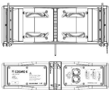
Driven via a passive x-over, this two-way M/H line array unit is loaded with two 6.5" midrange woofers and a 1.4" HF driver fronted by a Multicell Transformer (MCT). With 100° horizontal directivity, it is perfect for short throw distances.
• C 8 mid/high unit
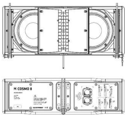
Driven via a passive x-over, this two-way M/H line array unit is loaded with two 8" midrange woofers and a 1.4" HF driver fronted by an MCT. With 80° horizontal directivity, it is perfect for medium-range throw distances
• C 10 mid/high unit

Driven via a passive x-over, this two-way M/H line array unit is loaded with 10" midrange woofers and two 1.4" tweeters fronted by MCTs. With 60° horizontal directivity (optional 80° by installing the brackets supplied), it is perfect for longer throw distances.
• CF 118 subwoofer

natural_image
Pure geometric pattern with no text, numbers, or symbolsThis passive, flyable bass reflex subwoofer is loaded with an 18" woofer and equipped with a Pin Assignment switch.
- CS 118 subwoofer
natural_image
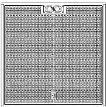
Close-up of a textured fabric panel with repeating patterns and a small 'R' label (no readable text or symbols)This passive bass refl ex subwoofer is loaded with an 18" woofer and equipped with a Pin Assignment switch.
• CS 218 subwoofer

natural_image
Interior view of a grid-patterned room or enclosure with no visible text, numbers, or symbols.This passive bass reflex subwoofer is loaded with two 18" woofers and equipped with a Pin Assignment switch.
→ Please consult the appendix for all other technical specifications, measurements and scale diagrams
2.2 Amps and Controllers

natural_image
Front view of a server rack unit with multiple drive bays and indicator lights (no visible text or labels)Engineered to deliver the best audio results, the HK Audio C-DRIVE 4 and C-DRIVE 8 amp racks provide the perfect engine room for the amps that drive COSMO systems. Featuring a shock-mount suspension and double sliding doors, these racks are well equipped for the rigors of professional use on the road. They ship with Lab. Gruppen (LC) and Powersoft (PS) amplifiers.
• C-DRIVE 8 LG 12K44 / 5K44
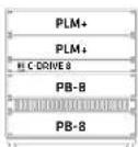
2x 4 output channels
Factory included: 2x Lab, Gruppen PLM+12K44 (or 5K44),
2x PB-8 patchbay. 1x PS 32 power supply, 2x blank panel, 10U quick-shut rack
• C-DRIVE 4 LG 12K44 / 5K44
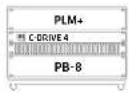
4 output channels
Factory included: 1x Lab.Gruppen PLM+12K44 (or SK44), 1x PB-8 patchbay, 1x PS 32 power supply, 2x blank panel, 6U quick-shut rack
• C-DRIVE 8 PS X4 / T604

2x 4 output channels
Factory included: 2x Powersoft X4 (or T604), 2x PB-8 patchbay, 4x blank panel, 10U quick-shut rack
• C-DRIVE 4 PS X4 / T604

4 output channels
Factory included: 1x Powersoft X4 (or T604), 1x PB-8 patchbay, 3x blank panel, GU quick-shut rack
2.3 Speaker Cables

LSM
This four-channel multicore speaker cable is available in various lengths.

LSM Mid/High
This NL8-to-4x NL4 adapter serves to connect four COSMO M/H units.

LSM Sub
This NL8-to-4x NL4 adapter serves to connect four subwoofers.

2.4 Rigging and Transport Hardware
• CRF-80 rigging frame - art. no. 1007678

natural_image
Technical line drawing of a mechanical assembly with rollers and mounting holes (no text or symbols)The multifunctional CRF-80 serves as a rigging frame for C 6, C 8 and C 10 M/H units, or for arrays with the CF 118. The CRF-80 may also be used for ground stacks.
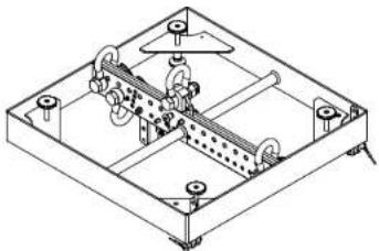
- CRF-60 rigging frame - art. no. 1007677
natural_image
Isometric technical drawing of a mechanical assembly with gears and housing (no text or symbols)The multifunctional CRF-60 serves as a rigging frame for C 6, C 8 and C 10 M/H units, or for ground stacks.
• CRF-PB pull-back frame - art. no. 1007679

natural_image
Technical line drawing of a mechanical assembly with no visible text or symbolsThe CRF-PB pullback frame serves to fly cabinets in compressed mode, to place up M/H units on speaker stands, or to stack M/H units.
• C-PPA pick-point adapter - art. no. 1007680

The pick-point adapter serves to attach chain hoists and other suitable lifting devices to the rigging frame.
• C-M20 adapter - art. no. 1007681
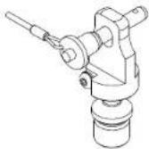
The C-M20 adapter serves to securely connect the rigging frame or pullback frame to ground-stacked C-SUB subwoofers.
• C-GSA ground stack adapter - art. no. 1007682

The C-GSA ground stack adapter serves to connect ground-stacked mid/high units to the rigging frame, and tilt the cabinets at angles up to -20°.
- C-STR tensioning strap (not pictured) - art. no. 1007707 This tensioning strap comes with a BSC (belt slip control) ratchet for compressed mode rigging.
• COSMO and C SUB wheel boards

natural_image
Technical line drawing of a multi-tiered modular cart or storage unit (no text or symbols)C-WB for M/H units - art. no. 1007638
The compact C-WB wheel board comes with a protective lid. It provides an easy, space-saving way of transporting COSMO M/H units. The cover's length is adjustable, so the C-WB can accommodate various combinations of COSMO M/H units. They are stored and transported at a D^ angle on the C-WB.
CS-WB 1 (for the CS 118) - art. no. 1007700
CS-WB 2 (for the CS 218) - art. no. 1007699
These two compact wheel boards provide an easy, space-saving way of transporting C SUB series subwoofers. The matching covers keep the speaker cabinets well-protected during transport and in storage.
CF-DO (for CF 118) - art. no. 1007769
The CF-DO dolly board provides a safe means of transporting the CF 118. With the optional CF-DO Extension, you can use its base for ground stacks.
CF-DO Extension - art. no. 1007770
This optional extension for the CF-DO dolly board provides a convenient means of stacking the CF 118 with C 6, C 8 or C 10 mid/high units on the ground.
The following table goes to help you plan your logistics. It indicates COSMO transport accessories' size and weight when loaded with speakers.
• COSMO transport accessories take up the following amounts of truck space:

Truck loading space
 | [0627] | 60 x 50 cm3x C 8 (6x)(84 kg / 185 lbs) |
| [8088] | [0827] | 60 x 80 cm2x CS 118(108 kg / 238 lbs) |
| [7708] |  | 60 x 80 cm2x CF 118(132 kg / 291 lbs) |
| [KBCT] |  | 120 x 80 cm2x CS 218(190 kg / 419 lbs) |
 |  | 60 x 55 cm1x C-DRIVE 4(60 kg / 132 lbs) |
| [7CBY] | [XYZ7] | 60 x 70 cm1x C-DRIVE 8(87 kg / 192 lbs) |
 | [0088] | 60 x 80 cm2x CRF-60(80 kg / 175 lbs) |
| [4TOH] | 60 x 80 cm2x CRF-80(92 kg / 203 lbs) |
2.5 Software
EASE Focus 3
Simulation data sets are available in GLL format for all COSMO and C SUB series loudspeakers. With EASE Focus 3, you can map out the direct sound for defined coverage areas. Free and easy to understand, it is an indispensable tool for planning line arrays.
• Vendor: AFMG Technologies GmbH
• Download it at http://focus.afmg.eu.
- Matching GLL files are available at www.hkaudio.com.
EASE 4.4
You can also use these GLL data sets with the industry standard EASE 4.4 software to simulate other factors beyond the room's acoustics to take into account variables such as the noise floor and frequency masking at various levels. This lets you do things like make realistic predictions as to the speech intelligibility in any given room. Another possibility is auralization, where you can model a sound system's performance while taking the room's acoustics into account. This is a great way of giving a less knowledgeable customer an idea of what kind of an audio image can actually be achieved in that venue.
Lake
Lake Controller software provides an interface that lets you control Lab.gruppen PLM+ series power amps, and monitor their status and the connected speaker loads. It serves to monitor the amplifiers' status and the connected speaker loads. Featuring lots of customizing and control options, this software runs best on wireless tablet PCs. www.labgruppen.com.
Armonía
Powersoft also offers a professional platform for controlling its DSP technology. Called ArmoniaPlus, it furnishes everything you need to plan, monitor and fine-tune PAs. Download Armonia at www.powersoft-audio.com.

Please visit the given vendor's website to learn more about the software and system requirements.
3 Connectors and Speaker Cables
• C 6, C 8, C 10 mid/high units
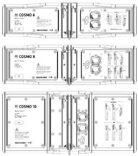
Each COSMO M/H unit is equipped with two parallel NL4 Speaker connectors. The input accepts the signal-carrying speaker cable; the output serves to connect further speaker cabinets.

Connector pin assignments
| 1+/1- | HF/MF signal |
| 2+/2- | THRU |
• CF 118, CS 118, CS 218 subwoofers
Each CF 118, CS 118 and CS 218 subwoofer is equipped with two parallel NL4 connectors on the front and rear. They serve to connect the signal-carrying speaker cable and route the signal on to other speakers. The built-in Pin Assignment switch configures the signal taps.

Pin Assignment switch settings:
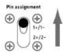
| Pin assignments when set to 1+/1- | |
| 1+/1- | SUB signal |
| 2+/2- | THRU |
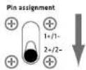
| Pin assignments when set to 2+/2- | |
| 1+/1- | THRU |
| 2+/2- | SUB signal |

The PB-8 is the central input/output hub for all HK Audio amp racks.
| XLR audio inputs | |
| XLR Analog In CH1 • CH 2 • CH 3 • CH 4 | |
| XLR Analog Thru CH 1 • CH 2 • CH 3 • CH 4 | |
| XLR AES 3 CH 1/2 • CH 3/4 | |
The analog Thru connectors let you route the incoming signal on to a downstream amp. The built-in switch severs the signal-carrying line's ground circuit.
The two Ethernet ports serve control purposes and as an interface for the Dante® interface. The Ethernet ports may be used as a switch in conjunction with the amp platforms and as redundant ports for the Dante interface.
Four speaker outputs are at your disposal:
The eight NL4 outputs are four-pole connectors with two channels each. The channels assigned to the given amplifier output may be tapped via pin 1+/-, and the second channel via 2+/-. The bottom NL4 outputs are connected in parallel to the top NL4 outputs.
The four channels are configured as follows when you use the NL8 output:
| NL8 connector pin assignments | |
| 1+/-CH 1 | |
| 2+/-CH 2 | |
| 3+/-CH 3 | |
| 4+/-CH 4 | |
Please consult the appendix for all other technical specifications and information about the patchbay's internal wiring.
Connecting COSMO M/H units
The table indicates how many mid/high units may be connected to each channel. The recommended minimum electrical impedance for each channel is 2.66 ohms.
| Number of mid/high units per channel | |
| C 6 6 units per channel | |
| C 8 3 units per channel | |
| C 10 2 units per channel | |

flowchart
graph TD
    subgraph PB-8
        A["Ch 1"] --> B["CH 2"]
        C["Ch 3"] --> D["Ch 4"]
        E["Ch 4"] --> F["Output"]
    end
    subgraph CH_1
        G["Pin 1"] --> H["Pin 2"]
        I["Pin 3"] --> J["Pin 4"]
        K["Pin 4"] --> L["Pin 5"]
        M["Pin 5"] --> N["Pin 6"]
        O["Pin 6"] --> P["Pin 7"]
        Q["Pin 7"] --> R["Pin 8"]
        S["Pin 8"] --> T["Pin 9"]
        U["Pin 9"] --> V["Pin 10"]
        W["Pin 10"] --> X["Pin 11"]
        Y["Pin 11"] --> Z["Pin 12"]
        AA["Pin 12"] --> AB["Pin 13"]
        AC["Pin 13"] --> AD["Pin 14"]
        AE["Pin 14"] --> AF["Pin 15"]
        AG["Pin 15"] --> AH["Pin 16"]
        AI["Pin 16"] --> AJ["Pin 17"]
        AK["Pin 17"] --> AL["Pin 18"]
        AM["Pin 18"] --> AN["Pin 19"]
        AO["Pin 19"] --> AP["Pin 20"]
        AQ["Pin 20"] --> AR["Pin 21"]
        AS["Pin 21"] --> AT["Pin 22"]
        AU["Pin 22"] --> AV["Pin 23"]
        AW["Pin 23"] --> AX["Pin 24"]
        AY["Ch 1"] --> AZ["Pin 2"]
        BA["Ch 2"] --> BB["Pin 3"]
        BC["Ch 3"] --> BD["Pin 4"]
        BE["Ch 4"] --> BF["Pin 5"]
        BG["Ch 5"] --> BH["Pin 6"]
        BI["Ch 6"] --> BJ["Pin 7"]
        BK["Ch 7"] --> BL["Pin 8"]
        BM["Ch 8"] --> BN["Pin 9"]
        BO["Ch 9"] --> BP["Pin 10"]
        BQ["Ch 10"] --> BR["Pin 11"]
        BS["Ch 11"] --> BT["Pin 12"]
        BU["Ch 12"] --> BV["Pin 13"]
        BW["Ch 13"] --> BX["Pin 14"]
        BY["Ch 14"] --> BZ["Pin 15"]
        CA["Ch 15"] --> CB["Pin 16"]
        CC["Ch 16"] --> CD["Pin 17"]
        DD["Ch 17"] --> DJ["Pin 18"]
        DK["Ch 18"] --> DL["Pin 19"]
        DV["Ch 19"] --> DW["Pin 20"]
        BXN["Ch 20"] --> BXN
        BYX["Ch 21"] --> BYX
        BZL["Ch 22"] --> BZL
        BZM["Ch 23"] --> BZM
        BZN["Ch 24"] --> BZN
        BZO["Ch 25"] --> BZO
        BZP["Ch 26"] --> BZP
        BZQ["Ch 27"] --> BZQ
        BZR["Ch 28"] --> BZR
        BZS["Ch 29"] --> BZS
        BZT["Ch 30"] --> BZT
    end
    subgraph HF_signal
    direction TB
    H["HF signal 1+/-"]
    end
Connecting subwoofers
Connect no more than two CS 118/CF 118 (or one CS 218 unit) to each channel. The recommended minimum electrical impedance for each channel is 4 ohms.

flowchart
graph TD
    A["PB-8"] --> B["Ch1"]
    A --> C["Ch2"]
    A --> D["Ch3"]
    A --> E["Ch4"]
    A --> F["..."]
    A --> G["..."]
    A --> H["..."]
    A --> I["..."]
    A --> J["..."]
    A --> K["..."]
    A --> L["..."]
    A --> M["..."]
    A --> N["..."]
    A --> O["..."]
    A --> P["..."]
    A --> Q["..."]
    A --> R["..."]
    A --> S["..."]
    A --> T["..."]
    A --> U["..."]
    A --> V["..."]
    A --> W["..."]
    A --> X["..."]
    A --> Y["..."]
    A --> Z["..."]
    A --> AA["..."]
    A --> AB["..."]
    A --> AC["..."]
    A --> AD["..."]
    A --> AE["..."]
    A --> AF["..."]
    A --> AG["..."]
    A --> AH["..."]
    A --> AI["..."]
    A --> AJ["..."]
    A --> AK["..."]
    A --> AL["..."]
    A --> AM["..."]
    A --> AN["..."]
    A --> AO["..."]
    A --> AP["..."]
    A --> AQ["..."]
    A --> AR["..."]
    A --> AS["..."]
    A --> AT["..."]
    A --> AU["..."]
    A --> AV["..."]
    A --> AW["..."]
    A --> AX["..."]
    A --> AY["..."]
    A --> AZ["..."]
    A --> BA["..."]
    A --> BB["..."]
    A --> BC["..."]
    A --> BD["..."]
    A --> BE["..."]
    A --> BF["..."]
    A --> BG["..."]
    A --> BH["..."]
    A --> BI["..."]
    A --> BJ["..."]
    A --> BK["..."]
    A --> BL["..."]
    A --> BM["..."]
    A --> BN["..."]
    A --> BO["..."]
    A --> BP["..."]
    A --> BQ["..."]
    A --> BR["..."]
    A --> BS["..."]
    A --> BT["..."]
    A --> BU["..."]
    A --> BV["..."]
    A --> BW["..."]
    A --> BX["..."]
    A --> BY["..."]
    A --> BZ["..."]
    A --> CA["..."]
    A --> CB["..."]
    A --> CC["..."]
    A --> CD["..."]
    A --> CE["..."]
    A --> CF["..."]
    A --> CG["..."]
    A --> CH["..."]
    A --> CI["..."]
    A --> CJ["..."]
    A --> CK["..."]
    A --> CL["..."]
    A --> CM["..."]
    A --> CN["..."]
    A --> CO["..."]
    A --> CP["..."]
    A --> CQ["..."]
    A --> CR["..."]
    A --> CS["..."]
    A --> CT["..."]
    A --> CU["..."]
    A --> CV["..."]
    A --> CW["..."]
    A --> CX["..."]
    A --> CY["..."]
    A --> CZ["..."]
Using the COSMO multicore cable
• LSM Mid/High adapter (art. no. 1006166)
The LSM Mid/High adapter is a convenient way of connecting larger systems. The LSM Mid/High adapter's NL4 pin assignments are two poles to pin 1+/-. See section 5, "Example Setups," for more on this.
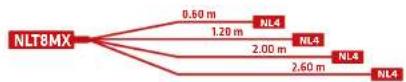
• LSM Sub adapter (art. no. 1006167)
The LSM Sub adapter is a convenient way of connecting larger systems. The LSM Sub adapter's NL4 pin assignments are two poles to pin 2+/-. The subwoofer's Pin Assignment switch has to set to the 2+/- position.

flowchart
graph LR
    A["NLT8MX"] --> B["5.00 m"]
    A --> C["5.00 m"]
    A --> D["5.00 m"]
    A --> E["5.00 m"]
    A --> F["5.00 m"]
    A --> G["NL4"]
    A --> H["NL4"]
    A --> I["NL4"]
• NL8 Multicore
LSM 5 (art. no. 1007712) length 5 m
LSM 10 (art. no. 1007713) length 10 m
LSM 15 (art. no. 1007714) length 15 m
LSM 20 (art. no. 1006165) length 20 m

4 Controller Settings
The following filters are available for operating the system's components with Lake and Armonía controller software.
Filters for COSMO M/H units
| C 6 | |
| "C 6 - FR" (Fullrange) "C 6 - LC" | Low Cut) |
| C 8 | |
| "C 8 - FR" (Fullrange) "C 8 - LC" | Low Cut) |
| C 10 | |
| "C 10 - 60° FR" (Fullrange) "C 10 | - 80° LC" (Low Cut) |
| "C 10 - 80° FR" (Fullrange) "C 10 | - 80° LC" (Low Cut) |
Filters for C SUB subwoofers
| CF 118 |
| "CF 118 - Flat" "CF 118 - Boost" "CF 118 - Sub Low" |
| CS 118 |
| "CS 118 - Flat" "CS 118 - Boost" "CS 118 - Sub Low" |
| CS 218 |
| "CS 218 - Flat" "CS 218 - Boost" "CS 218 - Sub Low" |
CS Flat: for large arrays with 12 or more M/H units
CS Boost: for small arrays with up to 12 M/H units or for ground stacks
CS Sub Low: for CF 118, CS 118 and CS 218 sub low add-ons
If you wish to use Lake, there are also compensation overlays (filters) available for arrays of varying lengths:
| EQ array compensation overlays | ||
| 6 to 8 cabinets | 9 to 11 cabinets | 12 to 20 cabinets |
4.1 Recommended filters
COSMO mid/high units and C SUB series subwoofers are designed for the most diverse applications. Use the recommended filter to adapt them to the given application. These EQ setups have been tested and proven.
- Standalone M/H units:

The recommendation for mid/high units deployed as standalone units such as near-fills and the like is to activate each unit's low-cut filter.
- M/H unit array:

The recommendation for arrays consisting of just one type of mid/high unit - that is, setups consisting solely of C 6, C 8 or C 10 cabinets - is to active the fullrange preset for each cabinet.
Lake: Be sure to select the right EQ overlay for the given number of deployed mid/high units when using Lake.
Armonia: It provides ready-to-use modules with compensation built in, so you do not need to select the appropriate EQ overlays in Armonia.
- Arrays with added subwoofers:

We recommend the following filter combinations for arrays with added C SUB bass bins:
| C 6 / C SUB | |
| for "CS Flat" or "CS Sub Low" | "C 6 - FR" |
| for "CS Flat" or "CS Boost" | "C 6 - LC" |
| C 8 / C SUB | |
| for "CS Flat" or "CS Sub Low" | "C 8 - FR" |
| for "CS Flat" or "CS Boost" | "C 8 - LC" |
| C 10 / C SUB | |
| for "CS Flat" or "CS Sub Low" | "C 10 - FR" |
| for "CS Flat" or "CS Boost" | "C 10 - LC" |
We recommend the following
M/H-unit-to-subwoofer ratios

Three C 6 / C 8 to two C5/CF 118
Three C 6 / C 8 to one CS 218

Two C 10 to two CS/CF 118
Two C 10 to one CS 218
5 Example Setups
1

flowchart
graph TD
    A["HF signal 1+/-"] --> B["Setup: 18x C6 8x CS 118"]
    C["LF signal 2+/-"] --> B
    D["2x CS 118 = 1x CS 218"] --> B
    B --> E["Audio In: L/R or L/R + Sub"]
    E --> F["C-DRIVE 4"]
    E --> G["C-DRIVE 4"]
    E --> H["PB-8"]
    F --> I["1"]
    F --> J["3"]
    G --> K["1"]
    G --> L["3"]
    H --> M["1"]
    H --> N["3"]
    I --> O["Total weight*: 1038 kg/2288 lbs"]
    J --> O
    K --> O
    L --> O
    M --> P["2.4 m / 55""]
    N --> Q["2.4 m / 55""]
    O --> R["WB 1 WB 1 WB"]
    O --> S["C-WB C WB WB 1"]
    O --> T["C-WB CRF-60 C-DRIVE 4"]
    P --> U["2.4 m / 55""]
    Q --> V["2.4 m / 55""]
2

flowchart
graph TD
    A["HF signal 1+/-"] --> B["Setup: 12x C 8 8x CS 118"]
    C["LF signal 2+/-"] --> B
    D["2x CS 118 = 1x CS 218"] --> B
    B --> E["Audio In: L/R or L/R + Sub"]
    E --> F["C-DRIVE 4"]
    E --> G["C-DRIVE 4"]
    F --> H["PB-8"]
    G --> I["PB-8"]
    H --> J["1"]
    H --> K["3"]
    I --> L["1"]
    I --> M["4"]
    J --> N["2"]
    J --> O["4"]
    K --> P["2"]
    K --> Q["4"]
    L --> R["1"]
    L --> S["3"]
    M --> T["2"]
    M --> U["4"]
    N --> V["1"]
    N --> W["3"]
    O --> X["2"]
    O --> Y["4"]
    P --> Z["1"]
    P --> AA["3"]
    Q --> AB["2"]
    Q --> AC["4"]
3

flowchart
graph TD
    A["HF signal 1+/-"] --> B["Setup: 8x C 10 8x CS 118"]
    C["LF signal 2+/-"] --> B
    D["2x CS 118 = 1x CS 218"] --> B
    B --> E["C-DRIVE 4"]
    B --> F["C-DRIVE 4"]
    B --> G["PB-8"]
    E --> H["Audio In: L/R or L/R + Sub"]
    F --> I["Audio In: L/R or L/R + Sub"]
    G --> J["Audio In: L/R or L/R + Sub"]
    H --> K["Total weight*: 919 kg 2026 lbs"]
    I --> K
    J --> K
    style A fill:#f9f,stroke:#333
    style C fill:#f9f,stroke:#333
    style D fill:#f9f,stroke:#333
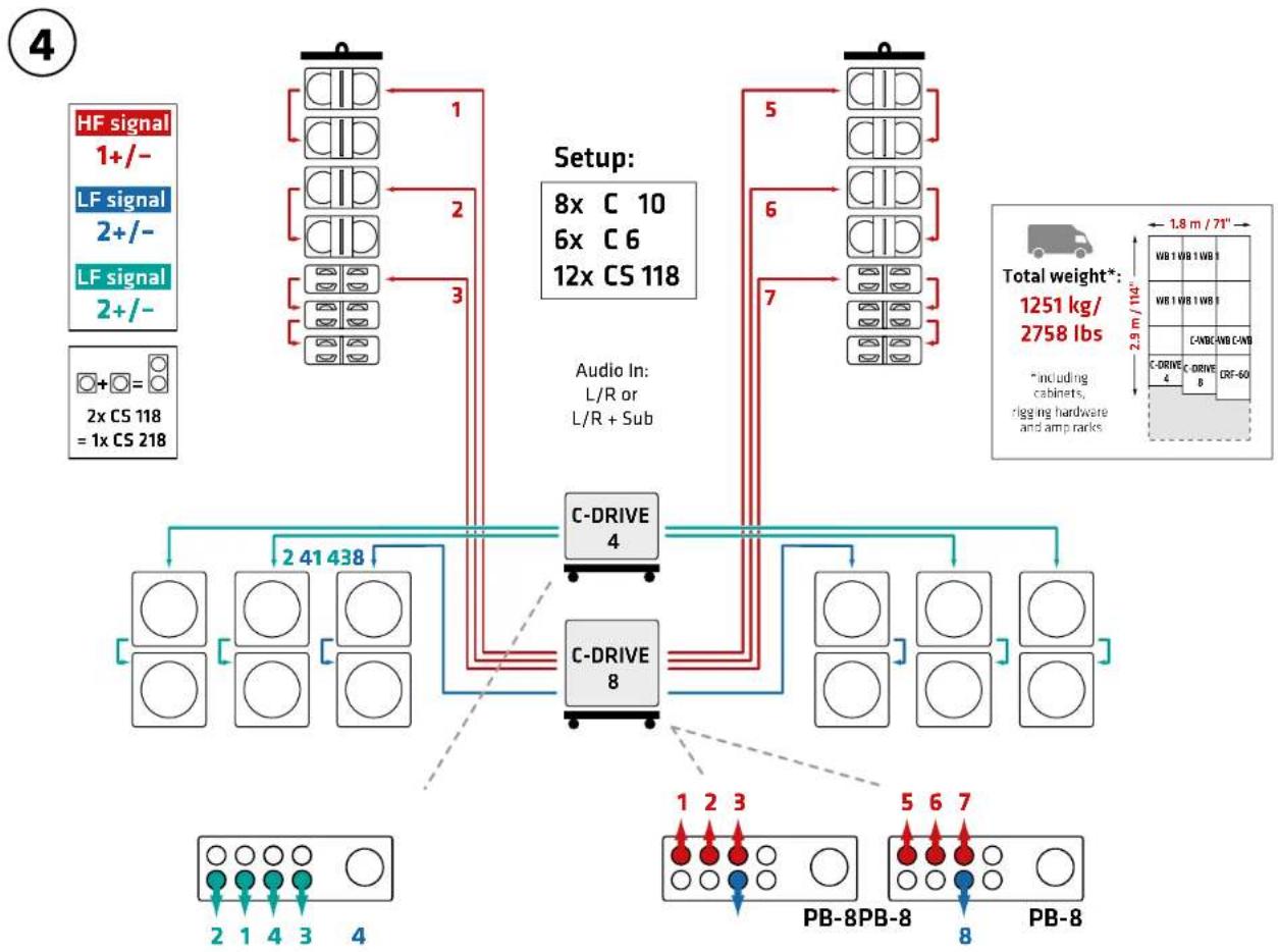
flowchart
graph TD
    A["HF signal 1+/-"] --> B["Setup: 8x C 10 6x C 6 12x CS 118"]
    C["LF signal 2+/-"] --> B
    D["LF signal 2+/-"] --> B
    E["2x CS 118 = 1x CS 218"] --> B
    B --> F["Audio In: L/R or L/R + Sub"]
    F --> G["C-DRIVE 4"]
    F --> H["C-DRIVE 8"]
    G --> I["2 41 438"]
    H --> J["2 41 438"]
    I --> K["2 1 4 3 4"]
    J --> L["2 1 4 3 4"]
    K --> M["PB-8PB-8"]
    L --> N["PB-8"]
    M --> O["1 2 3"]
    N --> P["5 6 7"]
    O --> Q["7"]
    P --> R["5"]
    Q --> S["6"]
    R --> T["7"]
    S --> U["1"]
    T --> V["1.8 m / 71""]
    U --> W["WB 1 WB 1 WB 1"]
    V --> X["WB 1 WB 1 WB 1"]
    W --> Y["C-DRIVE 4"]
    X --> Z["C-DRIVE 4"]
    Y --> AA["CRF-60"]
    Z --> AB["CRF-60"]
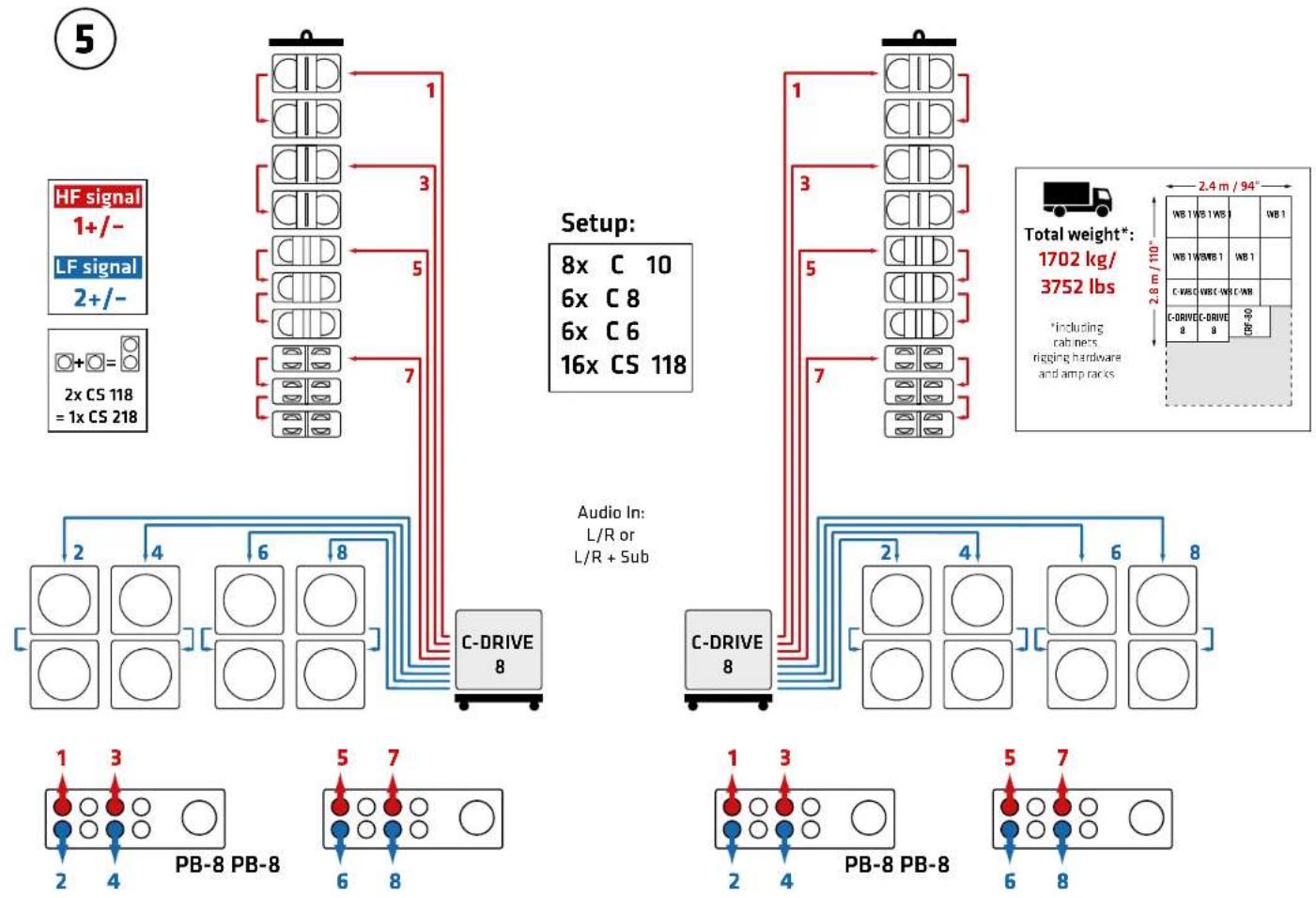
flowchart
graph TD
    A["HF signal 1+/-"] --> B["C-DRIVE 8"]
    C["LF signal 2+/-"] --> B
    D["2x CS 118 = 1x CS 218"] --> B
    B --> E["Setup: 8x C 10, 6x C 8, 6x C 6, 16x CS 118"]
    E --> F["Audio In: L/R or L/R + Sub"]
    F --> G["C-DRIVE 8"]
    H["Total weight*: 1702 kg/3752 lbs"] --> I["WB 1 WB 1 WB 1 WB 1 WB 1 WB 1 WB 1 WB 1 WB 1 WB 1 WB 1 WB 1 WB 1 WB 1 WB 1 WB 1 WB 1 WB 1 WB 1 WB 1 WB 1 WB 1 WB 1 WB 1 WB 1 WB 1 WB 1 WB 1 WB 1 WB 1 WB 1 WB 1 WB 1 WB 1 WB"]
    J["PB-8 PB-8"] --> K["1"]
    J --> L["3"]
    J --> M["5"]
    J --> N["7"]
    J --> O["6"]
    J --> P["8"]
    K --> Q["2"]
    K --> R["4"]
    K --> S["6"]
    K --> T["8"]
    L --> U["2"]
    L --> V["4"]
    L --> W["6"]
    L --> X["8"]
    M --> Y["2"]
    M --> Z["4"]
    M --> AA["6"]
    M --> AB["8"]
    N --> AC["2"]
    N --> AD["4"]
    N --> AE["6"]
    N --> AF["8"]
    O --> AG["2"]
    O --> AH["4"]
    O --> AI["6"]
    O --> AJ["8"]

flowchart
graph TD
    A["HF signal 1+/-"] --> B["C-DRIVE 8"]
    C["LF signal 2+/-"] --> B
    D["2x CS 118 = 1x CS 218"] --> B
    B --> E["Setup: 12x C 10, 6x C 6, 4x CF 118, 6x CS 218"]
    E --> F["Audio In: L/R or L/R + Sub"]
    G["PB-8 PB-8"] --> H["C-DRIVE 8"]
    I["PB-8 PB-8"] --> J["C-DRIVE 8"]
    K["Total weight*: 1762 kg/3885 lbs"] --> L["WB 2 WB 2"]
    M["2.9 m / 114""] --> N["WIB ZCF-DOCF-DD"]
    O["1"] --> P["1"]
    Q["3"] --> R["3"]
    S["5"] --> T["5"]
    U["7"] --> V["7"]
    W["1"] --> X["1"]
    Y["3"] --> Z["3"]
    AA["5"] --> AB["5"]
    AC["7"] --> AD["7"]
    AE["1"] --> AF["1"]
    AG["3"] --> AH["3"]
    AI["5"] --> AJ["5"]
    AK["7"] --> AL["7"]
    AM["2"] --> AN["2"]
    AO["4"] --> AP["4"]
    AQ["6"] --> AR["6"]
    AS["2"] --> AT["2"]
    AU["4"] --> AV["4"]
    AW["6"] --> AX["6"]
    AY["2.4 m / 94""] --> Z
    AZ["2.9 m / 114""] --> AA
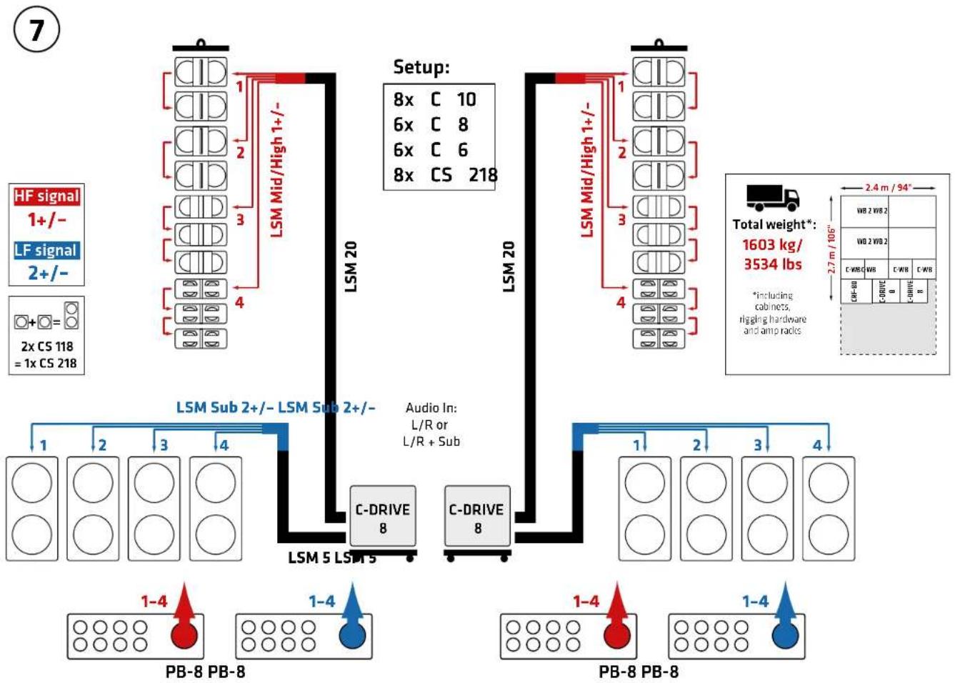
flowchart
graph TD
    A["HF signal 1+/-"] --> B["LSM Mid/High 1+/-"]
    C["LF signal 2+/-"] --> D["LSM Mid/High 1+/-"]
    E["2x CS 118 = 1x CS 218"] --> F["LSM Mid/High 1+/-"]
    G["Setup: 8x C 10, 6x C 8, 6x C 6, 8x CS 218"] --> H["LSM Mid/High 1+/-"]
    I["Total weight*: 1603 kg/3534 lbs"] --> J["WB 2 WB 2"]
    K["Audio In: L/R or L/R + Sub"] --> L["C-DRIVE 8"]
    M["PB-8 PB-8"] --> N["1-4"]
    O["PB-8 PB-8"] --> P["1-4"]
    Q["Setup: 8x C 10, 6x C 8, 6x C 6, 8x CS 218"] --> R["LSM Mid/High 1+/-"]
    S["Setup: 8x C 10, 6x C 8, 6x C 6, 8x CS 218"] --> T["LSM Mid/High 1+/-"]
    U["Total weight*: 2.7 m / 106°"] --> V["C-WB WR"]
    W["Total weight*: 2.4 m / 94°"] --> X["C-WB WR"]
8

flowchart
graph TD
    A["Pin assignment"] --> B["Subs must be switched to 1+/-"]
    B --> C["1+/1-2+/2-"]
    C --> D["LSM Mid/High 1+/-"]
    D --> E["LSM 5"]
    E --> F["C-DRIVE 4"]
    F --> G["LSM 5"]
    G --> H["1-4"]
    H --> I["PB-8"]
    H --> J["1-4"]
    J --> K["PB-8"]
    L["Setup"] --> M["8x C 8, 4x C 6, 4x CS 118"]
    M --> N["Audio In: L/R or L/R + Sub"]
    N --> O["C-DRIVE 4"]
    O --> P["LSTM 5"]
    P --> Q["1-4"]
    Q --> R["PB-8"]
    Q --> S["1-4"]
    S --> T["PB-8"]
    U["Pin assignment"] --> V["Subs must be switched to 1+/-"]
    V --> W["1+/1-2+/2-"]
    W --> X["HF signal 1+/- LF signal 1+/-"]
    Y["Total weight*: 723 kg/1594 lbs"] --> Z["VIB 1/W B1 CRF-60"]
    AA["1.8 m / 71""] --> AB["C-VB GWDC-WB"]
    AC["*including cabinets, rigging hardware and amp racks"] --> AD["C-DRIVE 4 C DRIVE 4"]

COSMO
Rigging Manual 2.0
1 Notes on Rigging Safety 25
2 Planning Arrays 27
3 Intended Use 30
4 Rigging Hardware 31
5 Connecting Hardware and Curving Arrays .... 35
6 Curving in Compressed Mode.... 36
7 Curving in Fixed Mode 39
8 Setting Up a CF 118 Array 42
9 Setting Up Ground Stacks 44
10 Disassembling Flown Arrays 49
1 Notes on Rigging Safety

This symbol, wherever it appears, alerts you to the presence of a crush hazard. Perform every step correctly as instructed in the rigging manual to avoid pinch/ries.

This symbol, wherever it appears, alerts you to the presence of hoisted heavy the event of a sudden fall or other uncontrolled movement, these loads can cause personal injury with potentially fatal consequences and considerable property. Keep people out of the danger zone at all times. Follow the plans in this manual.


Wear suitable headgear, gloves, and footwear during mechanical hazards and injuries.
- Rigging hardware
Use the rigging hardware for no purpose other than to set up HK audio speaker cabinets in flown arrays or ground stacks. Do not hoist components other than those that are part of this system. Use HK Audio speaker cabinets only as intended with the original rigging hardware. Use only original replacement parts.
- Prerequisites for installing the COSMO Line Array
Use only 2006/42/EC-compliant, manufacturer-certified lifting accessories or, in countries beyond the 2006/42/EC directive's purview, equivalent devices as specified by local regulations.
Follow these installation instructions. The indicated working load limit cannot be guaranteed and the manufacturer will not be liable for damages in the event of improper installation or the use of unauthorized rigging hardware. The system's working load limit cannot be guaranteed and the manufacturer will not be liable for damages in the event that loudspeakers, rigging hardware, connecting and fastening components, or lifting accessories are modified in any way. Components affecting safety may only be repaired by the manufacturer or authorized agents; otherwise the operating permit will be voided. Before installing the system, make sure the supporting structure and attachment points are suitable for this purpose and have the required load-handling capacity.
Do not exceed specified limits such as maximum working load limit and curvature and tilt angles. For more on this, please refer to the instructions in section 3, intended Use. When hoisting any load, make sure its center of gravity is directly below the attachment point or load-bearing component to protect against the hazard of a swinging load. The operator is to ensure the individuals tasked with operation, assembly and disassembly, maintenance, inspection, and the like are qualified to perform the given task. Heed the specifications as to the intended use of the system and its components. Designate only qualified specialists as set out in the rigging manual to assemble and disassemble the system. The operator is to determine and ensure the personnel tasked to do this have the necessary qualifications in keeping with the complexity of the fixed or mobile installation and the applicable local laws, regulations, and engineering rules. Train operating personnel in compliance with the instructions for use.
Provide adequate lighting during assembly and disassembly, cleaning, troubleshooting, maintenance, and repair. Heed Directive 89/654/EEC as transposed into local law.
• Curving in compressed mode
Use only tensioning devices such as ratchet or lashing straps with self-locking mechanisms, for example, hooks with a safety catch, to curve arrays. Make sure the tensioning device is able to gradually release tension, step by step. Keep a watchful eye on the system and beware of sudden and unexpected movements.
- Safe application
Installation is to be carried out by qualified personnel only, and only at attachment points with a sufficient working load limit. Heed the local building code and building regulations. Do not stand below the system or between the system and walls, fixtures or any other surrounding object when hoisting, lowering, assembling, disassembling or otherwise moving the system. Caution, crush/pinch hazard. Do not reach in between parts of the system when hoisting and lowering it. Keep a watchful eye on the system and beware of sudden and unexpected movements.
Wear PPE (personal protective equipment) to protect hands and feet when assembling and disassembling the system. Everyone in the vicinity when setting up and tearing down, curving, or troubleshooting flown arrays is to wear protective headgear. Use only suitable climbing aids such as ladders, scaffolds and the like. The sole responsibility for seeing to this lies with installing company.
The operator is obligated to allow only those persons to work with the rigging hardware who are:
- at least 18 years old
• physically and mentally able
• familiar with the basic rules of industrial safety and accident prevention
- trained to perform the given tasks. The same applies to assembly, disassembly, operation, maintenance, troubleshooting, maintenance, and inspection.
If there are signs of an approaching thunderstorm when setting up systems outdoors, determine if it is safe to do so and refrain from doing so if it is unsafe. If a thunderstorm arrives, stop all work on the system, ensuring no one touches conductive parts, and clear the area of people. Seek cover in a room or safe area, and continue monitoring weather forecasts.
Do not use the system or its components to hoist and secure people.
Clearly designate the responsibilities of personnel tasked to perform activities such as transporting, storing, putting into service, installing, dismantling, operating, maintaining, repairing, inspecting, and disposing of the system, and ensure the designated individuals are qualified to do so. If personnel lack the necessary qualifications, this work may be carried out under the supervision of qualified personnel in cases of extreme urgency. Immediately rectify defects and other damage that may impair safety.
Regularly check personnel for work safety awareness.
When attaching the rigging frame without a pick-point adapter, always do so with two suitable shackles fastened to the center perforated rails. Always use the pick-point adapter when attaching the rigging frame to a single load line.
Observe the permissible load angle when using two load lines. The wider the lines are splayed, the greater the load, especially when these lines are short. Never exceed the given lifting accessory's working load limit for the given load angle.
Secure fixed and mobile installations – in this case, speakers with rigging hardware – with two independent devices to prevent them from falling. You may dispense with this secondary safety device or arrest wire in cases where the attaching device is intrinsically safe, requires tools to unfasten, and is secured with a locking mechanism to prevent it
from disengaging on its own. Heed the applicable local laws, regulations, and engineering rules. Install safety features so as to ensure components cannot drop any distance. Safeties must be able to catch accessories or parts that are loose or may become loose. Heed local regulations when using fasteners, attaching devices and lifting accessories. Factor potential dynamic forces ('jerk' forces) into the equation when determining the proper size and load-bearing capacity of fastening devices.
Ensure all components in the load line - shackles and other lifting accessories, fasteners, tensioning devices, hoisting equipment, load-bearing equipment, load-bearing structures, and the like - are suited to the purpose and rated for the working load limits need to lift and held the system in place. The area below the system is off limits; people may only enter it if all components in the load line are designed to be intrinsically safe. Components that are not expressly intended for overhead use above people may be suitable if they hold a load no greater than half of the specified working load limit.
Observe the applicable local laws, regulations, and engineering rules.
Store materials securely on a stable surface. Keep fire extinguishing equipment and passageways clear and accessible, particularly emergency escape and rescue routes. Do not step or climb on the system and its components.
If a flown system could be exposed to wind, use at least two suitable fasteners to secure it so as to prevent twisting and other unintentional movement. Make sure these fasteners exert no more force than necessary to prevent the system from moving significantly at safe operating wind speeds. Do not exert excessive force.
Do not deploy the system at unsafe wind speeds beyond the maximum allowable limit. Remove or lower and secure the system before the wind reaches wind force 8 or gusts at 20 m/s. Plan, coordinate and document these measures. Constantly monitor weather forecasts.
The wind speed limit may be lower for the stage, PA tower or other primary supporting structure. If so, be sure to abide by it.
If the wind speed limit for a stationary or mobile system is exceeded, clear the danger zone and close off the wider surroundings. The system may not be dismantled at winds exceeding the limit.
- Speaker stands
Be sure to observe speaker stands' working load limit. Note that for reasons of design and construction, most speaker stands are approved to bear centric loads only; that is, the speakers' mass has to be precisely centered and balanced. Ensure speaker stands are set up stably and securely. Take appropriate added measures to secure speaker stands, for example, when:
- the floor or ground surface does not provide a stable, secure base
• they are extended to heights that impede stability
• high wind pressure may be expected
- there is the risk that they may be knocked over by people
Special measures may become necessary as precautions against unsafe audience behavior. Do not set up speaker stands in evacuation routes and emergency exits. Ensure corridors are wide enough and put proper barriers and markings in place when setting speaker stands up in passageways. Mounting and dismounting are particularly hazardous tasks. Use aids suitable for this purpose. Observe the applicable local laws, regulations, and engineering rules when doing so.
- Ground stacks
Stack speakers carefully so as not to damage or impair the components' physical integrity:
- Stack speakers on a level and firm floor or ground surface to ensure sufficient stability
- If you wish to curve the stack to provide near-fill or bleacher coverage, make sure the
stack's center of gravity remains well within the rigging frame.
- Secure the ground stack to prevent it from tipping.
- Do not stack more than the designated maximum number of speaker cabinets.
- Use the adjustable feet only to level the system. Make sure the base does not incline in
any direction.
- Use the C-M20 adapter to prevent slippage.
- Improper use
Improper use of rigging frames and incorrect handling of this load-carrying equipment can pose a serious danger.
Never
- lift loads with a center of gravity that is not directly below, perpendicular to, and in line
with the pickup point, or exert diagonal force on suspended loads
- use lifting equipment to forcibly dislodge stuck or immovable loads
- step on any part of the system
- carry, lift or secure people with parts of the system
- climb up the system
- strike, knock or dent the rigging frame or other parts of the system
- remain below the system or in the danger zone when it is moved, raised or lowered
• perform repairs on parts of the system other than those expressly permitted by the
manufacturer
- exceed the system's and any other constituent components' working load limits
- operate the system in or with an unauthorized configuration, curvature or tilt angle
- use the rigging frame to suspend non-system speaker cabinets or other loads
- install the system with improperly or incompletely connected components
- use damaged components
- install the system to unstable structures or structures with insufficient load-bearing
capacity
- install or operate the system at excess wind speeds or temperatures, or in the event of
thunderstorms
- expose components to harmful substances such as acids and alkalis
• operate the system in areas with a potentially hazardous explosive atmosphere
- transport or store the system so as to expose it to heat, moisture, excessive mechanical
stress, or other destructive forces
- modify the system or its components without the manufacturer's express consent
Serious dangers associated with improper use include:
- severe-to-fatal injuries caused by one or all components of the system falling or tipping
- severe-to-fatal injuries when people are crushed between the system and surrounding objects
• severe-to-fatal injuries when people fall
- severe-to-fatal injuries caused by lightning during thunderstorms
- injuries when limbs are caught between parts of the system
- injuries caused by the sharp edges of a damaged system
- injuries caused by colliding with or being struck by parts of the system
Always keep the area below the system clear of people, unless all of the following conditions are met:
Supporting structures, hoisting equipment, hoisting accessories, fasteners, and all other components used with the system must be suitable for overhead operation.
All components that are part of and used with the system must be in safe operating condition and have been inspected and verified by qualified personnel.
Do not move the system over people.
Do not use the CRF-PB pull-back frame as a load-bearing device.
• Inspection and maintenance
HEADS UPI Upon installation, inspect the flown array consisting of rigging hardware and speakers to make sure it is securely attached. The operator of stationary or mobile speaker systems is obliged to regularly inspect or have a qualified party regularly inspect all components in compliance with the applicable local laws, regulations, and engineering rules, and to have any damage repaired immediately. We strongly advise keeping log books or the like to document all inspections.
Be sure to take into account structures and surfaces' stability and working load limit when deploying speakers outdoors permanently or for longer periods – in particular, the effects of wind and temperature and the added load of snow and ice.
The operator is to carry out a risk assessment for the given application. Be sure to also assess the components and personnel's suitability, taking into account the given operating conditions and interactions with the working environment.
The operator is to arrange for the following inspections:
- Prior to the first use and regularly thereafter, a qualified/competent person is to inspect the rigging hardware's individual parts and the components to be deployed to make sure they are in safe operating condition.
- In the event of a fall, overloaded system components, or other unusual incidents that inflict damage, the operator is to arrange for a qualified person to perform an ad hoc inspection of the affected components.
Heed the applicable local laws, regulations, and engineering rules as to the type, timing and scope of inspections, taking into account the given operating conditions.
The following criteria are to be included in the scope of inspections conducted prior to the first use, at regular intervals, and after unusual incidents that inflict damage:
Condition, damage, cracks, deformation, corrosion, function, operability, wear, detachable connectors' fastening and securing action, the effectiveness of locks and stops, the completeness of connecting elements, the legibility of the type label and working load limit.
The interval between regular inspections is not to exceed one year. Be sure to document inspections.
Also have a competent person inspect rigging hardware components for visible damage, wear, proper function and the legibility of markings, and visually confirm their operating reliability prior to each use.
If the inspector finds defects that impair safety or markings that are no longer clearly legible, take this equipment out of circulation and do not use it again until it has been properly repaired.
Qualified personnel is to inspect hoists, lifting accessories, fasteners and other components used in connection with the rigging hardware in compliance with local regulations and the given manufacturer's specifications. This inspection is to be carried out at least once a year by qualified persons, and by competent persons prior to each installation.
Do not expose components to mechanical stress, moisture and heat during transport and storage.
Use only approved substances for cleaning as set out in section 3, Intended Use. Protect components against harmful substances such as acids and alkalis.
The system's components are to be repaired by the manufacturer or by a specialized company authorized by the manufacturer to do so.
• Disassembly
The array may be brought into a state of unstable equilibrium during disassembly. For this reason, relieve the tension on load-bearing equipment and lower hoisting equipment only to the extent necessary to remove one component at a time.
When releasing tensioning straps that curve an array, keep people out of the array's potential range of motion until the fastener is fully released.
• Hearing protection
Professional loudspeaker systems can produce harmful volume levels. Even prolonged exposure to seemingly harmless levels starting at about 95 dBA SPL can cause permanent hearing loss. We recommend that everyone who is exposed to high volume levels produced by loudspeaker systems wears professional hearing protection (earplugs or earmuffs).
Manufacturer: Stamer Musikanlagen GmbH, Magdeburger Str. 8, 66606 St. Wendel, Germany
2 Planning Arrays
2.1 Acoustic modeling with EASE Focus 3
Before deploying a COSMD line array, plan its setup with EASE Focus 3. This simulation software lets you map specific areas to be covered or to be left uncovered by individual sound sources. Its views show you the direct SPL throw pattern and/or the signal-to-noise ratios for the various frequency ranges. With this information, you can make a general prediction about the COSMD line array's ability meet the given application's acoustical requirements. The software clearly displays the mid/high units and their set angles once you align them as you see fit in the simulation. We recommend having a printout or screenshot of these angles at hand when you go to set up the array.

When using the CRF-60/CRF-BD to stack speakers on the ground, do not place more than six C 5, C 8, or C 10 units on top of one another, and no more than three C 5, C 8, or C 10 units when using the CRF-PB. Note that EASE Focus 3 will not accept higher numbers than that.
2.3 Mechanical limits
The CRF-80 rigging frame can hold no more than 20 C B, 20 C B, or 14 C 10 units. The CRF-60 can hold up to 14 C 6, 14 C 8, or 10 C 10 units. This rigging hardware is designed for standard array curvatures.
- Scenarios to determine limits as calculated by a structural engineer
We had a structural engineer investigate typical applications to our specifications. The tables on the following pages list these scenarios, indicating utilization ratios for the respective scenarios in percentages.
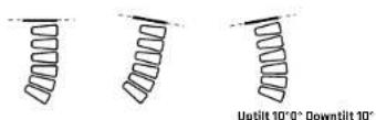
Uptilt and downtilt are the terms we use to describe the rigging frame's maximum permissible upward and downward angles of inclination for each configuration.
The following applies to these scenarios that define the respective limits:
- C B or C B M/H units can always replace C 10 M/H units.
- C 6 M/H units can always replace C 8 M/H units.
- Do not exceed the number of M/H units indicated in these examples.
- Do not exceed the overall down-tilt angle in the example scenario.
- Do not exceed the specified downtilt angles (range 0 to X*)
- Do not set uptilt angles any lower than indicated (range 0 to -X*)
- Never set angles between MJH units any lower than specified.
- Every scenario not addressed by these examples has to be reviewed and validated separately.

The calculations for utilization ratios (in %) given in the two tables below are based on the
updated flaps. You can identify these by their outer markings as shown in the figure below.
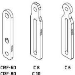
2.4 Scenarios to determine mechanical limits
Utilization by frame angle
| Straight Downtilt Uptilt | |||||||||||||
| No. | Type | Number of M/H units | Array angle configuration | Weight | Bottom at 0° | angleMode Utilization by load-bearing capacity | Angle Utilization by load-bearing capacity | Permissible angle of inclination | Utilization by load-bearing capacity | Permissible angle of inclination | |||
| 1 | C 8 | 10 | 1 × 10^4 , 5 × 10^4 |  | 251.4 kg | 96.8° | Fixed Mode Compressed Mode | 48%53% | 0°0° | 53%61% | -4.55°-4.55° | 36%26% | 31.61°31.61° |
| 2 | C 8 | 20 | 6 × 10^4 , 3 × 10^4 , 3 × 2^2 , 1 × 3^2 , 1 × 4^2 , 1 × 5^2 , 1 × 6^2 , 1 × 7^2 , 1 × 8^2 , 2 × 9^2 |  | 479.4 kg | 58.8° Fixed Mode | Compressed Mode | 62%52% | 0°0° | 100%96% | -6.66°-6.66° | 41%47% | 8.80°8.80° |
| 3 | C 8 | 16 | 1 × 10^4 , 5 × 7^2 |  | 388.2 kg | 43.0° Fixed Mode Compressed Mode | Fixed Mode Compressed Mode | 29%25% | 0°0° | 75%62% | -12.68°-12.68° | 34%35% | 5.95°5.95° |
| 4 | C 10 | 14 | 1 × 10^4 |  | 474.9 kg | 5.6° Fixed Mode Compressed Mode | Fixed Mode Compressed Mode | 33%27% | 0°0° | 99%52% | -11.57°-11.57° | 42%54% | 4.59°2.50° |
| 5 | C 10 | 10 | 1 × 10^4 , 5 × 6^2 |  | 345.9 kg | 58.8° Fixed Mode Compressed Mode | Fixed Mode Compressed Mode | 66%50% | 0°0° | 75%57% | -3.23°-3.23° | 40%34% | 21.58°21.58° |
Utilization by frame angle
| Straight Downtilt Uptilt | |||||||||||||
| No. | Type | Number of M/H units | Array angle configuration | Weight | Bottom angle Modus Utilization by load-bearing capacity at 0° | Angle Utilization by load-bearing capacity | Permissible angle of inclination | Utilization by load-bearing capacity | Permissible angle of inclination | ||||
| 6 C 10 | 14 | 4 × 0^ , 5 × 0^ , 1 × 2^ , 1 × 3^ , 1 × 4^ , 2 × 5^ |  | 474.9 kg | 31.6° Fixed Mode | Compressed Mode | 47%30% | 0°0° | 100%70% | -9.50°-9.50° | 41%41% | 6.93°6.93° | |
| 7 C 10 | +C 8 | 4+8 | 12 × 0^ |  | 334.8 kg | 7.2° Fixed Mode | Compressed Mode | 20%18% | 0°0° | 64%37% | -16.26°-16.26° | 29%53% | 5.58°3.00° |
| 8 C 10 | +C 8 | 4+8 | 2 × 0^ , 2 × 1^ , 3 × 2^ , 1 × 3^ , 1 × 4^ , 1 × 5^ , 1 × 6^ , 1 × 8^ |  | 334.8 kg | 41.2° Fixed Mode | Compressed Mode | 31%19% | 0°0° | 67%51% | -13.32°-13.32° | 29%28% | 5.24°9.24° |
| 9 C 10 | +C 8 | 4+8 | 1 × 0^ , 1 × 5^ | 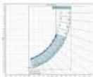 | 334.8 kg | 73.2° Fixed Mode | Compressed Mode | 65%56% | 0°0° | 72%62% | -2.91°-2.91° | 40%33% | 22.38°22.38° |
| 10 | C 10 + C 8 | 12+3 10 × 0^ | 2 × 2^ , 1 × 6^ , 1 × 7^ , 1 × 8^ |  | 478.8 kg | 32.8° Fixed Mode | Compressed Mode | 36%31% | 0°0° | 100%57% | -11.14°-11.14° | 42%23% | 4.94°4.94° |
SFγ 27
3 Intended Use
• Rigging and curving
Please read these instructions carefully before setting up and always keep them at hand when working on or with the system!
Use
- Intended use
This rigging hardware consisting of the CRF-60 and CRF-80 rigging frames, C-PPA pick-point adapter, CRF-PB pull-back frame, and C-STR tensioning strap is intended for installing the HK Audio COSMO series and CF 118 subwoofer in a flown array, permanently or temporarily, in compliance with the manufacturer's specifications.
The rigging frame may also serve to stack COSMO M/H units on the ground in compliance with the manufacturer's specifications.
Any use other than specified is unintended. The manufacturer shall not be liable for damages resulting from unintended use.
Note that the specifications for intended use require you to read and heed all of the operating instructions and comply with inspection and maintenance requirements. Heed all applicable local laws and regulations.
Use EASE Focus 3 software to model the configuration and loads prior to installation.
Follow the rigging manual's instructions to assemble and disassemble the system. Ensure connections are made properly by fully and completely inserting the quick-release pins, with three attachment points per M/H unit and four for the CF 118.
In compressed mode, tighten the tensioning device (e.g. tensioning strap) between the rigging frame and pull-back frame only to the extent necessary to achieve the desired curvature. Do not exert excess force on the system's components when tightening the tensioning device.
• Warranty and liability
HK Audio shall not be held responsible for damages due to improper use or failure to comply with the safety specifications in the operating manual and rigging manual.
All warranty and liability claims for personal injury and property damages are excluded if attributable to one or several of the following causes:
- failure to comply with operating manual instructions, voiding product liability and warranty claims
- unintended use and misuse of rigging frames
- failure to comply with the instructions in the operating manual and rigging manual as to the transport, storage, initial setup, installation, disassembly, operation, maintenance, repair, inspection, and disposal of the system's components
- unauthorized structural modifications to parts of the system - unauthorized modification of the parameters specified in the operating manual - inadequate or improper repairs
Storage, maintenance, inspection and repair of rigging hardware
• Storage and safekeeping when not in use
When the rigging hardware is not in use, store it in a safe place where it is protected against exposure to potentially harmful elements.
- Maintenance
You are authorized to replace easily serviceable wearing or standard parts in accordance with the manufacturer's instructions. Use original parts for this purpose. Tighten screws and bolted connections whenever necessary.
- Cleaning
Use mild liquid soap or similar cleaning agents only to clean the rigging hardware. Protect components against aggressive substances such as acids or strong alkalis.
- Repair
In the event that parts of the load-carrying equipment have been deformed, it is up to the manufacturer to determine if they are repairable.
Solely the manufacturer is authorized to perform welding and repair jobs on load-carrying equipment.
Technical specification for COSMO rigging hardware
- Working load limits
CRF-60 rigging frame 350 kg
CRF-80 rigging frame 700 kg
C-PPA pick-point adapter 1000 kg
Static test coefficient: 2.7 (the ratio of applied proof-load to the working load limit) Ambient operating temperature range: -10° to +60 °C Wind speed limits: <8 B, gust speed <20 m/s
• Maximum number of flown M/H units
The CRF-80 can accommodate up to twenty C 8s, twenty C 8s or fourteen C 10s. The CRF-60 can accommodate up to fourteen C6s, fourteen C 8s or ten C 10s. The rigging hardware is designed for common curved arrays. Please note the examples in the overview on page 27.
Be sure to add the weight of motors, cables and other hoisting gear when determining flown loads.
- Modifications to COSMO rigging hardware
No structural modifications may be made without the manufacturer's consent. This applies especially to welding work performed on load-bearing parts. Such alterations require the manufacturer's written approval.
• Original HK Audio accessories
Use original HX Audio accessories only. Using non-original aftermarket parts voids the manufacturer's product liability. Parts are to be installed as stated in the rigging manual. Store all documents pertaining to the system in a safe place.
| Wind force (s) | Speed (m/s) | Description Perceptible effects | |
| 0 v < 0,51 Calm Calm, smoke rises vertically | |||
| 1 D,51 ≤ v < 2,06 Light air | Direction shown by smoke drift but not by wind vanes | ||
| 2 | 2,06 ≤ v < 3,60 | Light breeze | Wind felt on face: leaves rustle: wind vane moved by wind |
| 3 | 3,60 < v < 5,66 | Gentle breeze | Leaves and small twigs in constant motion; light flags extended |
| 4 | 5.66 ≤ v < 8,23 | Moderate breeze | Raises dust and loose paper; small branches moved |
| 5 | 8,23 ≤ v < 11,32 | Fresh breeze | Small trees in leaf begin to sway; crested wavelets form on inland waters |
| 6 | 11.32 ≤ v < 14,40 | Strong breeze | Large branches in motion: whistling heard in telegraph wires; umbrellas used with difficulty |
| 7 | 14.40 ≤ v < 17,49 | High wind, moderate gale, near gale | Whole trees in motion: inconvenience felt when walking against the wind |
| 8 | 17,49 ≤ v < 21,09 | Gale, fresh gale | Twigs break off trees; generally impedes progress |
| 9 | 21,09 ≤ v < 24,69 | Strong/severe gale | Slight structural damage (chimney puts and slates removed) |
| 10 | 24,69 ≤ v < 28,81 | Storm, whole gale | Seldom experienced inland; trees uproated; considerable structural damage |
| 11 | 28.81 ≤ v < 32,92 | Violent storm Very rarely experienced; accompanied by widespread damage | |
| 12 | v ≥ 32.92 | Hurricane force | Devastation |
v = velocity
4 Rigging Hardware
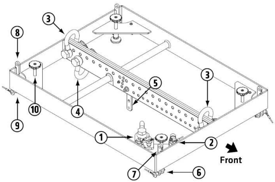
4.1 CRF-80 COSMO rigging frame
The COSMO CRF-80 serves as a rigging frame for all COSMO M/H units and for the CF 118. Able to hold up to 700 kg, it is used for large COSMO setups and for flown arrays with an added CF 118. In combination with the C-M20 adapter, this frame connects C SUB and COSMO M/H units in ground stacks.
① C-PPA pick-point adapter (in parking position)
② C-M20 adapter (in parking position)
③ Shackle pickup point for attaching suitable hoisting gear (two-point suspension) or secondary safeties
④ Shackle pickup point for securing the tensioning strap in compressed mode
⑤ Flap to connect an M/H unit's angle plate with the rigging frame
⑥ Front attachment point for mounting an M/H unit or a CF 118 to a fl own array
⑦ Front attachment point for mounting COSMO M/H units or a CF 118 in a ground stack or connecting a CF 118 and a COSMO M/H unit to a fl own array
⑧ Rear attachment point on a CF 118 when the frame serves as an adapter between a CF 118 and a COSMO M/H unit, or for ground stacks with the rigging frame and CF 118
⑨ Rear attachment point of a CF 118 in a flown array
10 Adjustable foot for leveling ground stacks
⑪ Marker to position the C-GSA ground stack adapter correctly
Dimensions: 780 x 137 x 600 mm
Weight: 19.1 kg
4 Rigging Hardware

- English
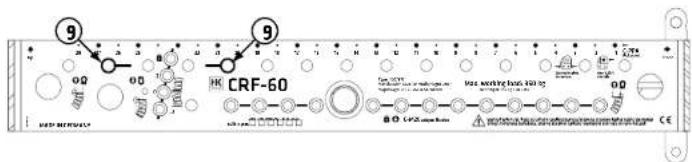
4.2 CRF-60 COSMO rigging frame
The COSMO CRF-60 serves as a compact rigging frame for all COSMO M/H units. With its dimensions and 350 kg working load limit, it is suitable for smaller COSMO setups. In combination with the C-M20 adapter, this frame connects C SUB and COSMO M/H units in ground stacks.
① C-PPA pick-point adapter (in parking position)
② C-M20 adapter (in parking position)
③ Shackle pickup point for attaching suitable hoisting gear (two-point suspension) or secondary safeties
④ Shackle pickup point for securing the tensioning strap in compressed mode
⑤ Flap to connect an M/H unit's angle plate with the rigging frame
⑥ Front attachment point for mounting an M/H unit to a fl own array
⑦ Front attachment point for mounting a COSMO M/H unit in a ground stack
8 Adjustable foot for leveling ground stacks
⑨ Marker to position the C GSA ground stack adapter correctly
Dimensions: 600 x 137 x 600 mm
Weight: 17.6 kg

4 Rigging Hardware
- English
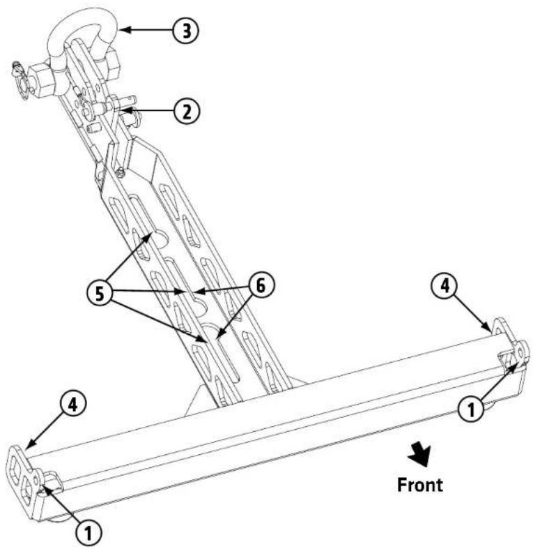
4.3 CRF-PB pull-back frame
The CRF-PB pull-back frame is used for compressed mode rigging with a tensioning strap, to mount no more than two COSMO M/H units on speaker stands, and to set up small ground stack applications with up to three M/H units.
① Front attachment point for mounting the frame below a COSMO M/H unit
② Spacers for attaching the frame to a COSMO M/H unit's angle plate
③ Shackles for attaching the tensioning strap
④ Attachment point for ropes to keep the flown array from twisting
⑤ Keyhole rail for attaching the C-M20 adapter to a C SUB series subwoofer
⑥ Keyhole rail for attaching a pole mount adapter to place a cabinet on a speaker stand

Heads up: Heed the manufacturer's specifications speaker stands' maximum centric load handling when speaking speaker stands. If necessary, secure the speaker to prevent from tipping.
Dimensions: 534 x 86 x 526 mm
Weight: 5.0 kg
4.4 C-PPA pick-point adapter
The pick point adapter serves to attach chain hoists and other suitable hoisting equipment to the rigging frame. It allows for variable positioning so you can adjust the array to the desired inclination. EASE Focus 3 simulation software tells you which pick-point to use.

① Shackle for attaching a chain hoist
② Shackle locking device
③ Quick-release pin to attach the C-PPA in the rigging frame's center mounting rail
④ Indicator point to show if the C-PPA has to be rotated 180°


4.5 C-M20 adapter
The C-M20 adapter serves to securely connect the rigging frame or pull-back frame to C SUB subwoofers in ground stacks.

① Quick release pin to attach the C-M20 in the rigging frame's center mounting rail
② M2D threaded insert for attaching the sub-adapter to a C SUB subwoofer's M2D pole mount
To mount the frame, screw the C-M20 adapter into the subwoofer's M20 threaded sleeve. Attach the rigging frame by inserting the C-M20 sub-adapter's quick-release pin at the desired position in the bottom line of holes.
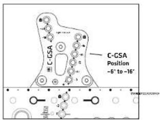
4.6 C-GSA ground stack adapter
The ground stack adapter lets you attach and tilt mid/high units in the rigging frame for ground stacks. You have a choice of nine angles for aiming speakers to suit the given application.

① Holes to adjust the tilt angle
② Quick-release pin to attach the C-GSA in the rigging frame's center mounting rail
4.7 C-STR tensioning strap (not shown)
The COSMO tensioning strap attaches to the pull-back frame's shackle to curve the array in compressed mode. This is a heavy-duty variant with a length of five meters and a belt slip control. The ratchet may be released step by step.
5 Connecting Hardware and Curving Arrays
5.1 General information on connections
Flown arrays
A three-point system serves to connect COSMO line array's M/H units and rigging hardware. Two front-side, top and bottom attachment points connect the front of the components. The rigging hardware for the rear load line consists of an angle plate and flip at the back each M/H unit.

The flap links the individual components and is always attached to the angle plate of the bottom M/H unit in compressed or fixed mode. The M/H units C 6 and C 8 may be tilted by up to 10° in 1° steps. The maximum angle for the C 10 is 6°.
A four-point system without a tilt option serves to attach the CF 118 subwoofer to the CRF-80.
Transport
Store and transport the M/H units at a 0° angle on the C-WB wheel board. This way, you can connect the package of stowed M/H units directly to the rigging frame in compressed mode for fast, easy assembly. All loads are to be lifted by a chain hoist.
In ground stacks
In ground stacks, the individual components have to be connected to each other in fixed mode. The M/H unit's flap attaches directly to the rigging frame, to the C-CSA ground stack adapter, or to the angle plate of the COSMO M/H unit below it.
5.2 Compressed mode vs. fixed mode
Compressed mode

When rigging in compressed mode, first set up the line array at a 0" angle with the tilt of the individual M/H units preset on the angle plate. Then angle the array by tightening the C-STR tensioning to exert force on the pull-back frame.

Fig: A 5" angle in compressed mode (for fl own arrays only)
Fixed mode

In fixed mode, the individual parts are connected at a fixed angle, so you do not need a tensioning strap.

Fig: A 5° angle in fixed mode (fl own)
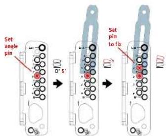
Fig: A 5" angle in fixed mode (ground stack)
6 Curving in Compressed Mode


Heads up: Setting up and tearing down
arrays can be dangerous. People may get hurt and property damaged if the rig or parts thereof fall, move in unexpected ways, or are improperly assembled and disassembled. Make sure quick-release pins, shackles and all other connecting components in the load line are properly engaged and secured to prevent them from loosening.


Wear suitable protective headgear,
gloves and footwear when assembling and disassembling the array.
The following instructions and illustrations apply to both the CRF-60 and CRF-80.
Note: These instructions for curving an array in compressed mode assume the mid/high units are mounted on the C-WB wheel board.
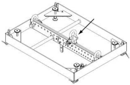
1 Attach the C-PPA pick-point adapter by inserting its two quick-release pins into the desired positions in the rigging frame's center mounting rail.
natural_image
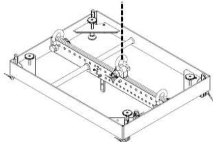
Technical line drawing of a mechanical assembly with mounting holes and a central rod (no text or symbols)2 Connect the chain hoist or other hoisting equipment to the C-PPA's shackle.
natural_image
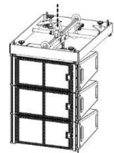
Isometric technical drawing of a mechanical assembly with no visible text or symbols3 Lift the rigging frame until there is sufficient clearance for the first C-WB wheel board to slide under it.

natural_image
Technical line drawing of a multi-tiered modular cart with mounting hardware (no text or symbols)
Heads up: You may dispense with a secondary device or arrest wire in cases where the attaching is intrinsically safe, requires tools to unfasten, and is with a locking mechanism to prevent it from aging on its own. Be sure to heed the applicable local regulations, and engineering rules.
4 First remove the C-WB's cover; then connect the top M/H unit to the rigging frame by inserting the two quick-release pins on the frame into the attachment points.

natural_image
Technical line drawing of a mechanical assembly with no visible text or symbols5 Attach the rigging frame's flap using the hole labeled link in this M/H unit's rear angle plate. Now insert the loose end of the tensioning strap with the crane hook into the rigging frame's lower shackle.

6 Remove the quick-release pins of the lowest M/H unit on the C-WB and lift the array until the entire load is suspended from the lifting accessories and link pins.

natural_image
Technical line drawing of a wheeled cart with wheels and mounting holes (no text or symbols)
natural_image
Technical line drawing of a mechanical cart with wheels and a highlighted circular component (no text or symbols)7 Now set all mid/high units' angle pins to the desired position on the angle plate (see the pictured example for a 4° angle).

Heads up: Remove and replace angle pins only when the array is suspended and there is no load on them: otherwise, you run the risk of pinch/crush injuries.
8 Raise the array just high enough for the next C-WB to slide in below it.
natural_image
Technical line drawing of a multi-tiered industrial or mechanical unit with internal components and mounting holes (no text or symbols)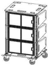
natural_image
Illustration of a multi-tiered modular cart with wheels and compartments (no text or symbols)9 Remove the C-WB's cover and insert the quick-release pins to connect the front sides of the M/H units (see step 4 above).
10 Attach the flap of the lowest suspended M/H unit to the link hole of the top M/H unit on the C-WB (see step 5 above).
Repeat steps 6 through 10 until all components required for the speaker array are connected.
11 Fold the flap of the lowest M/H unit in the array over into the angle plate to set it the parking position.

natural_image
Technical line drawing of a mechanical housing component with an arrow indicating rotation (no text or symbols present)12 Insert the two quick release pins to attach the CRF-PB to the lowest M/H unit in the array.

natural_image
Technical line drawing of a mechanical assembly with mounting holes and structural elements (no text or symbols)13 Insert quick-release pins to attach the pull-back frame's spacer adapter at the proper position in the M/H unit's angle plate.
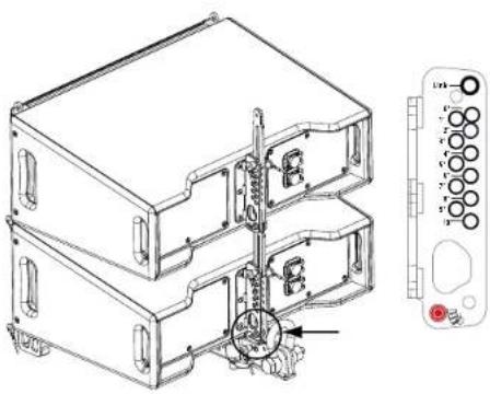
natural_image
Technical line drawing of a multi-tiered electronic device housing with internal components and a separate control panel (no text or symbols)14 Hook the red tensioning end of the tensioning strap into the CRF-PB's rear shackle and connect the loose and tensioning ends of the strap.

natural_image
Technical line drawing of a multi-tiered mechanical or electronic device with no visible text or symbols15 Engage the tensioning strap's ratchet until all flaps are fully attached to the angle pins and you arrive at the desired preset curvature.
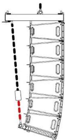
natural_image
Diagram of a vertical ladder structure with horizontal bars and a hanging weight, no text or symbols present
Heads up: Always keep the area below the system clear of people when raising or lowering it.

Heads up: You will feel some resistance when the fl aps mid/high units butt up against the angle pins. Do not tighten the strap any further as this may damage the rigging hardware.
16 You may fasten ropes to the pull-back frame's attachment points to tie the array to truss bars or the like to prevent it from twisting in the wind.

natural_image
Structural diagram of a vertical metal frame with horizontal supports and a small top component (no text or symbols)Note: Use only ropes with sufficient tensile strength to this end. Carabiner or snap hooks are suitable for attaching ropes.
7 Curving in Fixed Mode
Heads up: Setting up and tearing down arrays can be dangerous. People may get hurt and property damaged if the rig or parts thereof fall, move in unexpected ways, or are improperly assembled and disassembled. Make sure quick-release pins, shackles and all other connecting components in the load line are properly engaged and secured to prevent them from loosening.
Wear suitable protective headgear, gloves and footwear when assembling and disassembling the array.
The following instructions and illustrations apply to both the CRF-60 and CRF-80.
Note: Easy, safe rigging in fixed mode requires at least two people.
1 Attach the C-PPA Pick-point adapter by inserting its two quick-release pins into the desired positions in the rigging frame's mounting rail.
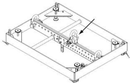
natural_image
Technical line drawing of a mechanical assembly with no visible text or symbols2 Connect the chain hoist or other hoisting equipment to the C-PPA's shackle and lift the rigging frame to a convenient working height.
Heads up: You may dispense with a secondary safety device or arrest wire in cases where the attaching device is intrinsically safe, requires tools to unfasten, and is secured with a locking mechanism to prevent it from disengaging on its own. Be sure to heed the applicable local laws, regulations, and engineering rules.

natural_image
Isometric technical drawing of a mechanical assembly with no visible text or symbols3 Insert the individual angle pins at the desired position and remove the fix pin from the M/H unit's angle plate before attaching each M/H unit.
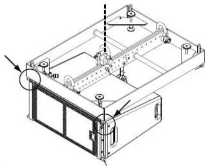
4 Insert the two quick-release pins that come with the rigging frame to attach the first M/H unit to the rigging frame's front attachment points.
natural_image
Technical line drawing of a mechanical assembly with mounting holes and internal components (no text or symbols)5 Insert the rigging frame's flap into the M/H unit's angle plate and lift it until the flap meets the angle pin.

Note: The angle between the frame and the first M/H unit should be 0°, the same angle as used in CLL data sets.
6 Insert the fix pin to secure the connection between the rigging frame and the first M/H unit.

7 Insert the quick-release pins to connect the front attachment points of this mid/high unit to the next mid/high unit.

natural_image
Technical line drawing of a server rack with mounting holes and ventilation ducts (no text or symbols)8 Insert the flap of the top M/H unit into the angle plate of the next M/H unit. Raise the M/H unit until the flap meets the angle pin (see the pictured example for a 5° angle).

natural_image
Technical line drawing of a mechanical assembly with internal components and a close-up view of a component (no text or symbols)9 Insert the fix pin to secure the connection between these two M/H units.

natural_image
Technical line drawing of a mechanical assembly with internal components and a separate view of a multi-pin connector (no text or symbols)10 Connect all further M/H units, one after the other, as described in steps 7 to 9 above until all M/H units intended for this array are connected.
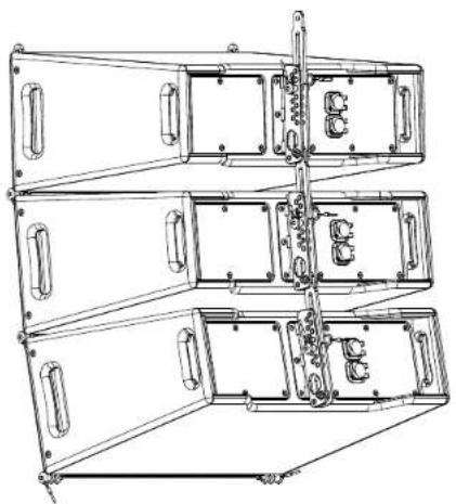
natural_image
Technical line drawing of a multi-tiered mechanical or electronic device with internal compartments and mounting brackets (no text or symbols)
Heads up: Always keep the area below the system of people when raising or lowering it.
11 You may fasten ropes to the pull-back frame's attachment points to tie the array to truss bars or the like to prevent it from twisting in the wind.

natural_image
Structural diagram of a multi-story building with vertical framework and horizontal supports (no text or symbols)Note: Use only ropes with sufficient tensile strength to this end. Carabiner or snap hooks are suitable for attaching ropes.
8 Setting Up a CF 118 Array

Heads up: Setting up and tearing down arrays can be dangerous. People may get hurt and property damaged if or parts thereof fall, move in unexpected ways, or properly assembled and disassembled. Make sure release pins, shackles and all other connecting elements in the load line are properly engaged and to prevent them from loosening.


gloves and footwear when assembling and disassembling the array.
You need two CRF-80s to set up arrays with CF 118 subwoofers - one to serve as a rigging frame and one as an adapter frame between the subwoofer and M/H unit.
1 Attach the C-PPA pick-point adapter by inserting its two quick release pins at the desired position in the rigging frame's center mounting rail. Connect the chain hoist or other hoisting equipment to the C-PPA's shackle.
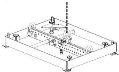
natural_image
Technical line drawing of a mechanical assembly with rollers and mounting brackets (no text or symbols)Note: The shackle for securing the tensioning strap is only required for the adapter frame (see step 6 above).

natural_image
Pure mechanical assembly diagram showing a bracket with holes and an arrow indicating direction (no text or symbols)Note: Make sure the flap is in the parked position and fixed in place with the pin.
2 Lift the rigging frame until there is sufficient clearance for the CF 118 subwoofer to slide under it.

natural_image
Technical line drawing of a mechanical device with wheels and mounting brackets (no text or symbols)
Heads up: You may dispense with a secondary device or arrest wire in cases where the attaching is intrinsically safe, requires tools to unfasten, and is d with a locking mechanism to prevent it from aging on its own. Be sure to heed the applicable local regulations, and engineering rules.
3 Connect the rigging frame to the CF 118 using the four attachment points.

natural_image
Technical line drawing of a mechanical device with wheels and mounting holes (no text or symbols)4 Follow the same steps to mount all other subwoofers required for the array below the suspended subwoofer.
5 Use the four attachment points at the bottom of the subwoofer to connect the second CRF-80 that is to serve as the adapter frame.

natural_image
Technical line drawing of a mechanical device with mounting holes and directional arrows indicating motion (no text or symbols)6 Now connect all M/H units required for the array to the adapter frame as described in sections 5 and 6 of this rigging manual.

natural_image
Technical line drawing of a mechanical or electrical component with no visible text, numbers, or symbols.7 You may fasten ropes to the pull-back frame's attachment points to tie the array to truss bars or the like to prevent it from twisting in the wind.
Note: Use only ropes with sufficient tensile strength to this end. Carabiner or snap hooks are suitable for attaching ropes.
Heads up: Always keep the area below the system clear of people when raising or lowering it.
Heads up: Please bear in mind that the working load limit is and will remain 700 kg. Using two CRF-80 rigging frames does not double the WLL.
9 Setting Up Ground Stacks

Heads up: Be sure to set the ground stack on a firm e and secure it to keep it from tipping.
Heads up: Setting up and tearing down ground stacks can be dangerous. People may get hurt and property damaged if the stack moves in unexpected ways or is improperly assembled and disassembled.
Make sure quick-release pins, shackles and all other connecting components are properly engaged and secured to prevent them from loosening.


Wear suitable protective headgear, when assembling and disassembling
The CS 118, CS 218 and CF 118 subwooters serve as the base for ground stacks. M/H units may be tilted at +2^ / 0^ / -2^ angles using the CRF-80 and CRF-60 rigging frames. If you need to tilt speakers further to aim them, you can use the optional C-CSA ground stack adapter to set larger angles from -6^ to -20^ . You can also use the CRF-PB pull-back frame for a ground stack. See section 9.4 for more on this.

Heads up: Make sure the ground stack's center of gravity remains within the base. Always secure the ground stack to prevent tipping.


Proceed with caution as you run the risk of a crush/pinch injury when connecting mid/high units.
The following instructions and illustrations apply to both the CRF-60 and CRF-80.
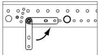
natural_image
Pure mechanical assembly diagram showing a bracket with holes and an arrow indicating direction (no text or symbols)Heads up: Flip the flap back for ground stacks with the CRF-60 or CRF-80.
9.1 Stacking speakers on top of a CS 118/CS 218 with the rigging frame only (+2°/0°/-2°)
1 Screw the C-M20 adapter into the CS 118 or CS 218's M20 threaded insert.

natural_image
Isometric line drawing of a rectangular electronic enclosure with ventilation grilles and a circular component on top (no text or symbols)2 Place the CRF-80 or CRF-60 on the subwoofer and insert the quick-release pin to attach it to the C-M20 adapter.

natural_image
Technical line drawing of a rectangular electronic enclosure with mounting holes and internal components (no text or symbols)3 Level the rigging frame with the four adjustable feet. The spirit level built into the CRF-60 or CRF-80 serves this purpose.

natural_image
Technical line drawing of a mechanical device with multiple circular components and ventilation grilles (no text or symbols)4 Attach the M/H unit to the rigging frame's attachment points.
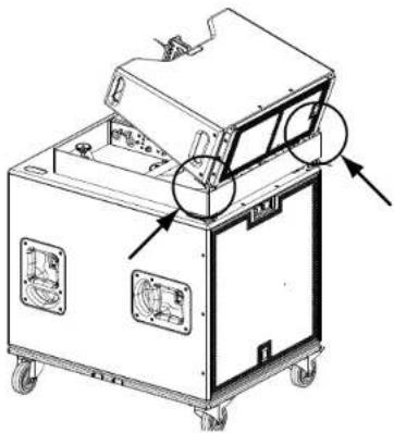
natural_image
Technical line drawing of a mechanical device with labeled components and directional arrows (no text or symbols)5 Example tilt angles:
Tilt set to -2°:
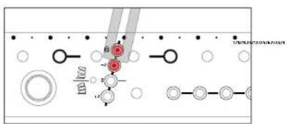
Tilt set to +2°:

6 Connect all other M/H units required for the ground stack in fixed mode.

Heads up: Never use a CRF-60 or CRF-80 to connect more than six COSMO M/H units to a ground stack
9.2 Stacking speakers on top of a CS 118/CS 218 with the rigging frame and the C-GSA ground stack adapter (-6° to -20°)
Follow steps 1 to 3 as described in section 9.1 to connect the rigging frame to the subwoofer.
1 Attach the C-GSA ground stack adapter by inserting its two quick release pins in the holes provided on the rigging frame.

natural_image
Technical line drawing of a mechanical assembly with no visible text or symbolsThe C-GSA has two rows of holes off ering the following angles: -6° to -16° or -18° to -20°. You can rotate the C-GSA 180° to achieve the desired angle.
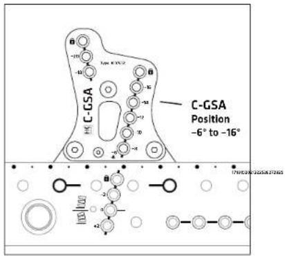

2 Attach the M/H unit to the rigging frame's attachment points.

natural_image
Technical line drawing of a mechanical device with wheels and mounting brackets (no text or symbols)3 Attach the flap to the C-CSA at the desired angle according the fixed mode procedure.
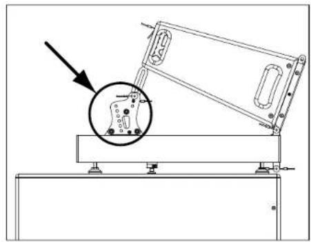
natural_image
Technical line drawing of a mechanical assembly with an inset showing a circular component (no text or symbols)4 Example tilt angles:
Tilt set to -16°
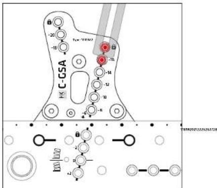
Tilt set to -6"
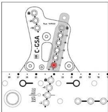
Note: -4^ tilt angle is not an option.
Note: A -6° tilt angle does not require an angle pin; the flap simply rests on the C-GSA. Secure this configuration with the Link pin.
5 Connect all other M/H units required for the ground stack in fixed mode.
9.3 Stacking speakers on top of a CF 118 with a CRF-80 rigging frame
1 Set the CRF-80 on the CF 118's rigging hardware.
2 Attach the rigging frame using the CF118's attachment points. You do not need a C-M20 adapter for this application.

natural_image
Technical line drawing of a mechanical device with mounting flanges and control panels (no text or symbols)3 Proceed as described in section 9.1 (-2° to +2°) or in section 9.2 (-6° to -20°), depending on the angle you wish to set.
9.4 Stacking speakers on top of a subwoofer with the CRF-PB pull-back frame

Heads up: Never stack more than three COSMO M/H in the ground using the CRF-PB.
1 Slide the C-M20 adapter into the CRF-PB's keyhole rail using the groove as a guide.

natural_image
Technical line drawing of a mechanical component with an inset showing a magnified detail of a component (no text or symbols present)2 Set the CRF-PB on the CS 118 or CS 218; then screw the C-M20 adapter into the subwoofer's M20 threaded insert. The pretensioning, due to screwing the adapter into the sub's threaded sleeve, affixes the CRF-PB to the top of the subwoofer.
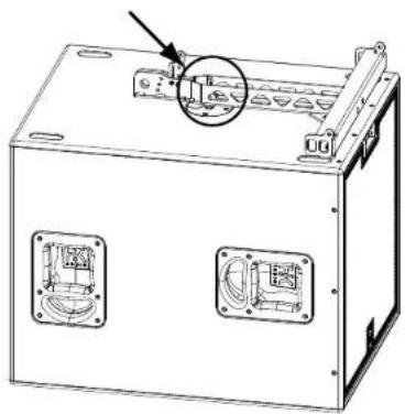
natural_image
Technical line drawing of a mechanical device with two mounting holes and a highlighted component (no text or symbols)3 Attach the COSMO M/H unit to the CRF-PB pull-back frame.

natural_image
Technical line drawing of a two-tiered industrial enclosure or enclosure unit (no text or symbols visible)4 You can set the M/H unit's angle on the CRF-PB to -5^ , -3^ , 0^ , +2^ or +5^ .
Setting the tilt angle with the CRF-PB's spacer:
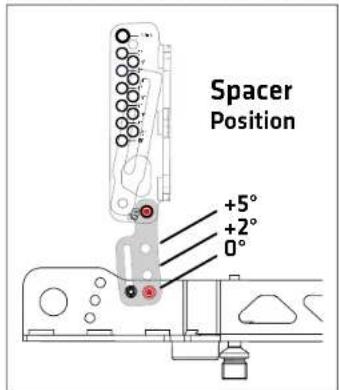
Setting the tilt angle with the M/H unit's flap
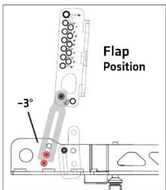

5 Connect all other M/H units required for the ground stack in fixed mode.
10 Disassembling Flown Arrays
10.1 Disassembling a compressed array

Heads up: Always keep the area below the system clear of people when raising or ing it.
1 Lower the array to a convenient working height.

Heads up: Make sure no one is in the danger zone designated above when you release sisioning strap.
2 Release the tensioning strap step by step until the array is perpendicular to the ground and the rear load is fully distributed across the link pins. Remove the CRF-PB together with the tensioning end of the tensioning strap.
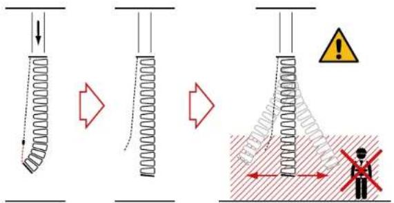
3 Set the angle pins of all M/H units within your reach at this working height to 0°. This connects the M/H units to each other at the 0° angle required for fixed mode.
4 Attach the C-WB to the lowest mid/high unit using the quick release pins on the C-WB. Now lower the array until the C-WB is stable, resting on a secure footing.

Make sure the C-WB is on secure footing before you move on to the next step.
5 Disconnect the top M/H unit of the stack that you want to roll away from the array.
6 Roll the C-WB out of the danger zone and connect the top M/H unit to the C-WB's cover. The loaded C-WB is now ready to go.
7 Repeat steps 3 through 6 until you have disassembled the entire array.
10.2 Disassembling a fixed array

Heads up: Always keep the area below the system clear of people when raising or g it.
Note: Easy, safe disassembly requires at least two people.
1 Lower the array to a convenient working height
2 Starting with the lowest M/H unit, remove the fix pin from the angle plate and the two pins from the front attachment points. This disconnects the M/H unit from the array so you can set it on a suitable means of transport such as a C-WB.
Note: This is a buddy-system job – you need two people to do it.
3 Repeat step 2 until you have removed all M/H units. Keep lowering the array to a convenient working height as you progress.
Recommendation: You can also take down several mid/high units in one go with the C-WB wheel board. See section 10.1 for more on this.
COSMO
Appendix 2.0
1 C6 mid/high unit 51
2 C 8 mid/high unit 54
3 C 10 mid/high unit 57
4 CF 118 subwoofer 60
5 CS 118 subwoofer 62
6 CS 218 subwoofer 64
7 PB-8 patchbay 66
8 Declarations of conformity 67
1 C 6 mid/high unit
C 6 - Technical specifications
| Power handling, nominal RMS 400 W | |
| Power handling, program 800 W | |
| Frequency response +/- 3 dB 75 Hz | 18 kHz |
| Frequency response - 10 dB 70 Hz - 19 kHz | |
| Sensitivity 1 W/1 m 102 dB (100 Hz + 10 kHz), full space | |
| Max. SPL @ 10 % THD(EN 602GB-21:2019) | 141 dB (3 units C 6) |
| Electrical impedance 16 ohms | |
| Low/mid speaker 2x 6,5", 2" voice coil | |
| HF Driver 1,4", 3" voice coil | |
| Directivity | 100° horizontal |
| Crossover frequency 1 kHz, 12 dB/octave | |
| Connections 2x Speakon NL4 (with sealing cap) | |
| Rigging points | 3-point rigging hardware with black KTL coating |
| Carrying handles | 4x recessed grip |
| Housing | Birch Multiplex |
| Finish | PU coating, black |
| Front grille | Steel front grille with anticorrosive coating, backed with acoustic foam |
| Dimensions (W x H x D) | 60 x 22 x 45 cm23-5/8 x 8-21/32 x 17-23/32" |
| Weight | 20.2 kg / 44.5 lbs |
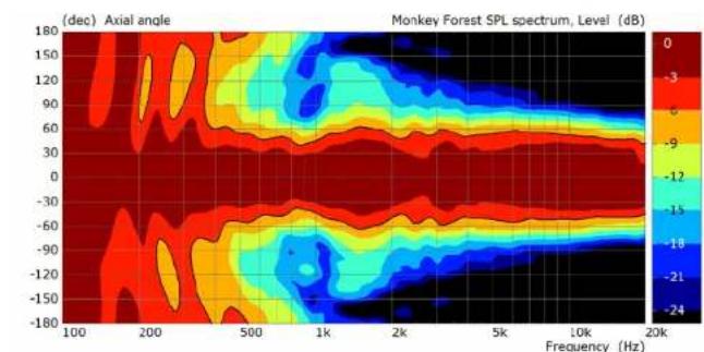
heatmap
| Frequency (Hz) | Axial angle (deg) | Level (dB) | | -------------- | ----------------- | ---------- | | 100 | -180 | 0 | | 200 | -150 | -3 | | 500 | -120 | -6 | | 1k | -90 | -9 | | 2k | -60 | -12 | | 5k | -30 | -15 | | 10k | 0 | -18 | | 20k | 30 | -21 | | 5k | 60 | -24 | | 10k | 90 | -24 | | 20k | 120 | -24 | | 5k | 150 | -24 | | 10k | 180 | -24 |Horizontal directivity

heatmap
| Frequency (Hz) | Axial angle (deg) | Level (dB) | | -------------- | ----------------- | ---------- | | 100 | -180 | -24 | | 100 | -150 | -21 | | 100 | -120 | -18 | | 100 | -90 | -15 | | 100 | -60 | -12 | | 100 | -30 | -9 | | 100 | 0 | -6 | | 100 | 30 | -3 | | 100 | 60 | 0 | | 200 | -180 | -24 | | 200 | -150 | -21 | | 200 | -120 | -18 | | 200 | -90 | -15 | | 200 | -60 | -12 | | 200 | -30 | -9 | | 200 | 0 | -6 | | 200 | 30 | -3 | | 200 | 60 | 0 | | 500 | -180 | -24 | | 500 | -150 | -21 | | 500 | -120 | -18 | | 500 | -90 | -15 | | 500 | -60 | -12 | | 500 | -30 | -9 | | 500 | 0 | -6 | | 500 | 30 | -3 | | 500 | 60 | 0 | | 1k | -180 | -24 | | 1k | -150 | -21 | | 1k | -120 | -18 | | 1k | -90 | -15 | | 1k | -60 | -12 | | 1k | -30 | -9 | | 1k | 0 | -6 | | 1k | 30 | -3 | | 1k | 60 | 0 | | 2k | -180 | -24 | | 2k | -150 | -21 | | 2k | -120 | -18 | | 2k | -90 | -15 | | 2k | -60 | -12 | | 2k | -30 | -9 | | 2k | 0 | -6 | | 2k | 30 | -3 | | 2k | 60 | 0 | | 5k | -180 | -24 | | 5k | -150 | -21 | | 5k | -120 | -18 | | 5k | -90 | -15 | | 5k | -60 | -12 | | 5k | -30 | -9 | | 5k | 0 | -6 | | 5k | 30 | -3 | | 5k | 60 | 0 | | 10k | -180 | -24 | | 10k | -150 | -21 | | 10k | -120 | -18 | | 10k | -90 | -15 | | 10k | -60 | -12 | | 10k | -30 | -9 | | 10k | 0 | -6 | | 10k | 30 | -3 | | 10k | 60 | 0 | | 20k | -180 | -24 | | 20k | -150 | -21 | | 20k | -120 | -18 | | 20k | -90 | -15 | | 20k | -60 | -12 | | 20k | -30 | -9 | | 20k | 0 | -6 | | 20k | 30 | -3 | | 20k | 60 | 0 |Vertical directivity (three C 6s at 0° splay)

line
| Frequency (Hz) | IFI: C6 - 3x0* + 3% THD | IFI: C6 + 3x0* + 10% THD | | -------------- | ------------------------ | ------------------------- | | 20 | 100 | 100 | | 50 | 125 | 125 | | 100 | 120 | 130 | | 200 | 125 | 130 | | 500 | 130 | 135 | | 1k | 125 | 140 | | 2k | 120 | 130 | | 5k | 115 | 125 | | 10k | 110 | 120 | | 20k | 105 | 115 |Max. SPL (blue=3% THD, red=10% THD)

heatmap
| Frequency (Hz) | Axial angle (deg) | Level (dB) | | -------------- | ----------------- | ---------- | | 100 | -180 | -24 | | 100 | -150 | -21 | | 100 | -120 | -18 | | 100 | -90 | -15 | | 100 | -60 | -12 | | 100 | -30 | -9 | | 100 | 0 | -6 | | 100 | 30 | -3 | | 100 | 60 | 0 | | 100 | 90 | 0 | | 100 | 120 | 0 | | 100 | 150 | 0 | | 100 | 180 | 0 | | 200 | -180 | -24 | | 200 | -150 | -21 | | 200 | -120 | -18 | | 200 | -90 | -15 | | 200 | -60 | -12 | | 200 | -30 | -9 | | 200 | 0 | -6 | | 200 | 30 | -3 | | 200 | 60 | 0 | | 200 | 90 | 0 | | 200 | 120 | 0 | | 200 | 150 | 0 | | 200 | 180 | 0 | | 500 | -180 | -24 | | 500 | -150 | -21 | | 500 | -120 | -18 | | 500 | -90 | -15 | | 500 | -60 | -12 | | 500 | -30 | -9 | | 500 | 0 | -6 | | 500 | 30 | -3 | | 500 | 60 | 0 | | 500 | 90 | 0 | | 500 | 120 | 0 | | 500 | 150 | 0 | | 500 | 180 | 0 | | 1k | -180 | -24 | | 1k | -150 | -21 | | 1k | -120 | -18 | | 1k | -90 | -15 | | 1k | -60 | -12 | | 1k | -30 | -9 | | 1k | 0 | -6 | | 1k | 30 | -3 | | 1k | 60 | 0 | | 1k | 90 | 0 | | 1k | 120 | 0 | | 1k | 150 | 0 | | 1k | 180 | 0 | | 2k | -180 | -24 | | 2k | -150 | -21 | | 2k | -120 | -18 | | 2k | -90 | -15 | | 2k | -60 | -12 | | 2k | -30 | -9 | | 2k | 0 | -6 | | 2k | 30 | -3 | | 2k | 60 | 0 | | 2k | 90 | 0 | | 2k | 120 | 0 | | 2k | 150 | 0 | | 2k | 180 | 0 | | 5k | -180 | -24 | | 5k | -150 | -21 | | 5k | -120 | -18 | | 5k | -90 | -15 | | 5k | -60 | -12 | | 5k | -30 | -9 | | 5k | 0 | -6 | | 5k | 30 | -3 | | 5k | 60 | 0 | | 5k | 90 | 0 | | 5k | 120 | 0 | | 5k | 150 | 0 | | 5k | 180 | 0 | | 10k | -180 | -24 | | 10k | -150 | -21 | | 10k | -120 | -18 | | 10k | -90 | -15 | | 10k | -60 | -12 | | 10k | -30 | -9 | | 10k | 0 | -6 | | 10k | 30 | -3 | | 10k | 60 | 0 | | 10k | 90 | 0 | | 10k | 120 | 0 | | 10k | 150 | 0 | | 10k | 180 | 0 | | 20k | -180 | -24 | | 20k | -150 | -21 | | 20k | -120 | -18 | | 20k | -90 | -15 | | 20k | -60 | -12 | | 20k | -30 | -9 | | 20k | 0 | -6 | | 20k | 30 | -3 | | 20k | 60 | 0 | | 20k | 90 | 0 | | 20k | 120 | 0 | | 20k | 150 | 0 | | 20k | 180 | 0 |Vertical directivity (three C 6s at 3° splay)

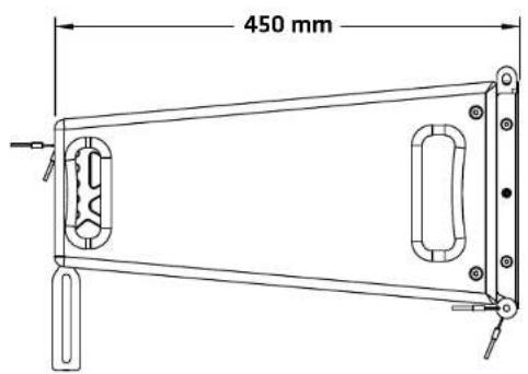

2 C 8 mid/high unit
C 8 - Technical specifications
| Power handling, nominal RMS 600 W | |
| Power handling, program 1200 W | |
| Frequency response +/-3 dB 63 Hz - | 18 kHz |
| Frequency response - 10 dB 57 Hz - | 19 kHz |
| Sensitivity 1 W/1 m 103 dB (100 Hz - | 10 kHz), full space |
| Max. SPL @ 10 % THD(EN 50268-21:2019) | 136 dB (3 units C 8) |
| Electrical impedance 8 ohms | |
| Low/mid speaker 2x 8", 7,5" voice coil | |
| HF Driver 1,4". 3" voice coil | |
| Directivity | 80° horizontal |
| Crossover frequency 800 Hz, 18 dB/ort. | |
| Connections 2x Speakon NL4 (with seeling cap) | |
| Rigging points | 3 point rigging hardware with black KTL coating |
| Carrying handles | 4x recessed grip |
| Housing | Birch Multiplex |
| Finish | PU coating, black |
| Front grille | Steel front grille with anticorrosive coating, backed withacoustic foam |
| Dimensions (W x H x D) | 60 x 27 x 45 cm23-5/8 x 10-5/8 x 17-23/32" |
| Weight | 22.8 kg / 50.2 lbs |

heatmap
| Frequency (Hz) | -180 | -150 | -120 | -90 | -60 | -30 | 0 | 30 | 60 | 90 | 120 | 150 | 180 | | -------------- | ------ | ------ | ------ | ------ | ------ | ------ | ------ | ------ | ------ | ------ | ------ | ------ | ------ | | 100 | -24 | -21 | -18 | -15 | -12 | -9 | -6 | -3 | 0 | 3 | 6 | 9 | 12 | | 200 | -24 | -21 | -18 | -15 | -12 | -9 | -6 | -3 | 0 | 3 | 6 | 9 | 12 | | 500 | -24 | -21 | -18 | -15 | -12 | -9 | -6 | -3 | 0 | 3 | 6 | 9 | 12 | | 1k | -24 | -21 | -18 | -15 | -12 | -9 | -6 | -3 | 0 | 3 | 6 | 9 | 12 | | 2k | -24 | -21 | -18 | -15 | -12 | -9 | -6 | -3 | 0 | 3 | 6 | 9 | 12 | | 5k | -24 | -21 | -18 | -15 | -12 | -9 | -6 | -3 | 0 | 3 | 6 | 9 | 12 | | 10k | -24 | -21 | -18 | -15 | -12 | -9 | -6 | -3 | 0 | 3 | 6 | 9 | 12 | | 20k | -24 | -21 | -18 | -15 | -12 | -9 | -6 | -3 | 0 | 3 | 6 | 9 | 12 |Horizontal directivity

heatmap
| Frequency (Hz) | Axial angle (deg) | Level (dB) | | -------------- | ----------------- | ---------- | | 100 | -180 | 0 | | 100 | -150 | -3 | | 100 | -120 | -6 | | 100 | -90 | -9 | | 100 | -60 | -12 | | 100 | -30 | -15 | | 100 | 0 | -18 | | 100 | 30 | -21 | | 100 | 60 | -24 | | 100 | 90 | -24 | | 100 | 120 | -24 | | 100 | 150 | -24 | | 100 | 180 | -24 | | 200 | -180 | 0 | | 200 | -150 | -3 | | 200 | -120 | -6 | | 200 | -90 | -9 | | 200 | -60 | -12 | | 200 | -30 | -15 | | 200 | 0 | -18 | | 200 | 30 | -21 | | 200 | 60 | -24 | | 200 | 90 | -24 | | 200 | 120 | -24 | | 200 | 150 | -24 | | 200 | 180 | -24 | | 500 | -180 | 0 | | 500 | -150 | -3 | | 500 | -120 | -6 | | 500 | -90 | -9 | | 500 | -60 | -12 | | 500 | -30 | -15 | | 500 | 0 | -18 | | 500 | 30 | -21 | | 500 | 60 | -24 | | 500 | 90 | -24 | | 500 | 120 | -24 | | 500 | 150 | -24 | | 500 | 180 | -24 | | 1k | -180 | 0 | | 1k | -150 | -3 | | 1k | -120 | -6 | | 1k | -90 | -9 | | 1k | -60 | -12 | | 1k | -30 | -15 | | 1k | 0 | -18 | | 1k | 30 | -21 | | 1k | 60 | -24 | | 1k | 90 | -24 | | 1k | 120 | -24 | | 1k | 150 | -24 | | 1k | 180 | -24 | | 2k | -180 | 0 | | 2k | -150 | -3 | | 2k | -120 | -6 | | 2k | -90 | -9 | | 2k | -60 | -12 | | 2k | -30 | -15 | | 2k | 0 | -18 | | 2k | 30 | -21 | | 2k | 60 | -24 | | 2k | 90 | -24 | | 2k | 120 | -24 | | 2k | 150 | -24 | | 2k | 180 | -24 | | 5k | -180 | 0 | | 5k | -150 | -3 | | 5k | -120 | -6 | | 5k | -90 | -9 | | 5k | -60 | -12 | | 5k | -30 | -15 | | 5k | 0 | -18 | | 5k | 30 | -21 | | 5k | 60 | -24 | | 5k | 90 | -24 | | 5k | 120 | -24 | | 5k | 150 | -24 | | 5k | 180 | -24 | | 10k | -180 | 0 | | 10k | -150 | -3 | | 10k | -120 | -6 | | 10k | -90 | -9 | | 10k | -60 | -12 | | 10k | -30 | -15 | | 10k | 0 | -18 | | 10k | 30 | -21 | | 10k | 60 | -24 | | 10k | 90 | -24 | | 10k | 120 | -24 | | 10k | 150 | -24 | | 10k | 180 | -24 | | 20k | -180 | 0 | | 20k | -150 | -3 | | 20k | -120 | -6 | | 20k | -90 | -9 | | 20k | -60 | -12 | | 20k | -30 | -15 | | 20k | 0 | -18 | | 20k | 30 | -21 | | 20k | 60 | -24 | | 20k | 90 | -24 | | 20k | 120 | -24 | | 20k | 150 | -24 | | 20k | 180 | -24 |Vertical directivity (three C 8s at 0" splay)
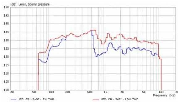
line
| Frequency (Hz) | IFC: CB - 3x0° - 3% THD | IFC: CB - 3x0° - 10% THD | | -------------- | ------------------------ | ------------------------- | | 20 | 120 | 120 | | 50 | 118 | 120 | | 100 | 125 | 130 | | 200 | 130 | 135 | | 500 | 135 | 135 | | 1k | 125 | 130 | | 2k | 120 | 125 | | 5k | 125 | 125 | | 10k | 120 | 120 | | 20k | 115 | 115 |Max. SPL (blue=3% THD, red=10% THD)

heatmap
| Frequency (Hz) | Axial angle (deg) | Level (dB) | | -------------- | ----------------- | ---------- | | 100 | -180 | 0 | | 100 | -150 | -3 | | 100 | -120 | -6 | | 100 | -90 | -9 | | 100 | -60 | -12 | | 100 | -30 | -15 | | 100 | 0 | -18 | | 100 | 30 | -21 | | 100 | 60 | -24 | | 100 | 90 | -24 | | 100 | 120 | -24 | | 100 | 150 | -24 | | 100 | 180 | -24 | | 200 | -180 | 0 | | 200 | -150 | -3 | | 200 | -120 | -6 | | 200 | -90 | -9 | | 200 | -60 | -12 | | 200 | -30 | -15 | | 200 | 0 | -18 | | 200 | 30 | -21 | | 200 | 60 | -24 | | 200 | 90 | -24 | | 200 | 120 | -24 | | 200 | 150 | -24 | | 200 | 180 | -24 | | 500 | -180 | 0 | | 500 | -150 | -3 | | 500 | -120 | -6 | | 500 | -90 | -9 | | 500 | -60 | -12 | | 500 | -30 | -15 | | 500 | 0 | -18 | | 500 | 30 | -21 | | 500 | 60 | -24 | | 500 | 90 | -24 | | 500 | 120 | -24 | | 500 | 150 | -24 | | 500 | 180 | -24 | | 1k | -180 | 0 | | 1k | -150 | -3 | | 1k | -120 | -6 | | 1k | -90 | -9 | | 1k | -60 | -12 | | 1k | -30 | -15 | | 1k | 0 | -18 | | 1k | 30 | -21 | | 1k | 60 | -24 | | 1k | 90 | -24 | | 1k | 120 | -24 | | 1k | 150 | -24 | | 1k | 180 | -24 | | 2k | -180 | 0 | | 2k | -150 | -3 | | 2k | -120 | -6 | | 2k | -90 | -9 | | 2k | -60 | -12 | | 2k | -30 | -15 | | 2k | 0 | -18 | | 2k | 30 | -21 | | 2k | 60 | -24 | | 2k | 90 | -24 | | 2k | 120 | -24 | | 2k | 150 | -24 | | 2k | 180 | -24 | | 5k | -180 | 0 | | 5k | -150 | -3 | | 5k | -120 | -6 | | 5k | -90 | -9 | | 5k | -60 | -12 | | 5k | -30 | -15 | | 5k | 0 | -18 | | 5k | 30 | -21 | | 5k | 60 | -24 | | 5k | 90 | -24 | | 5k | 120 | -24 | | 5k | 150 | -24 | | 5k | 180 | -24 | | 10k | -180 | 0 | | 10k | -150 | -3 | | 10k | -120 | -6 | | 10k | -90 | -9 | | 10k | -60 | -12 | | 10k | -30 | -15 | | 10k | 0 | -18 | | 10k | 30 | -21 | | 10k | 60 | -24 | | 10k | 90 | -24 | | 10k | 120 | -24 | | 10k | 150 | -24 | | 10k | 180 | -24 | | 20k | -180 | 0 | | 20k | -150 | -3 | | 20k | -120 | -6 | | 20k | -90 | -9 | | 20k | -60 | -12 | | 20k | -30 | -15 | | 20k | 0 | -18 | | 20k | 30 | -21 | | 20k | 60 | -24 | | 20k | 90 | -24 | | 20k | 120 | -24 | | 20k | 150 | -24 | | 20k | 180 | -24 | | ... (final) | ... | ... | | ... (final) | ... | ... | | ... (final) | ... | ... | | ... (final) | ... | ... | | ... (final) | ... | ... | | ... (final) | ... | ... | | ... (final) | ... | ... | | ... (final) | ... | ... | | ... (final) [final] (final) [final] (final) [final] (final) [final] (final) [final] (final) [final] (final) [final] (final) [final] (final) [final] (final) [final] (final) [final] (final) [final] (final) [final] (final) [final] (final) [final] (final) [final] (final) [final] (final) [actual] [actual] [actual] [actual] [actual] [actual] [actual] [actual] [actual] [actual] [actual] [actual] [actual] [actual] [actual] [actual] [actual] [actual] [actual] [actual] [actual] [actual] [actual] [actual] [actual] [actual]Vertical directivity (three C 8s at 3" splay)


3 C 10 mid/high unit
C 10 - Technical specifications
| Power handling, nominal RMS 800 W | |
| Power handling, program 1600 W | |
| Frequency response +/-3 dB 58 Hz - 18 kHz | |
| Frequency response - 10 dB 53 Hz - 19 kHz | |
| Sensitivity 1 W/1 m 108 dB (100 Hz | 10 kHz), full space |
| Max. SPL @ 10 % THD(EN 50268-21:2019) | 147 dB (3 units C 10) |
| Electrical impedance 8 ohms | |
| Low/mid speaker 2x 10", 2.5" voice coil | |
| HF Driver 2x 1.4", 3" voice coil | |
| Directivity 60° horizontal (80° optional) | |
| Crossover frequency 850 Hz, 12 dB/oct. | |
| Connections | 2x Speakon NL4 (with sealing cap) |
| Rigging points | 3-point rigging hardware with black KTL coating |
| Carrying handles | 4x recessed grip |
| Housing | Birch Multiplex |
| Finish | PU coating, black |
| Front grille | Steel front grille with anticorrosive coating, backed with acoustic foam |
| Dimensions (W x H x D) | 60 x 32 x 47.5 cm23-5/8 x 12-43/64 x 18-45/64" |
| Weight | 32.1 kg / 70.8 lbs32.4 kg / 71.4 lbs with 80° brackets mounted |
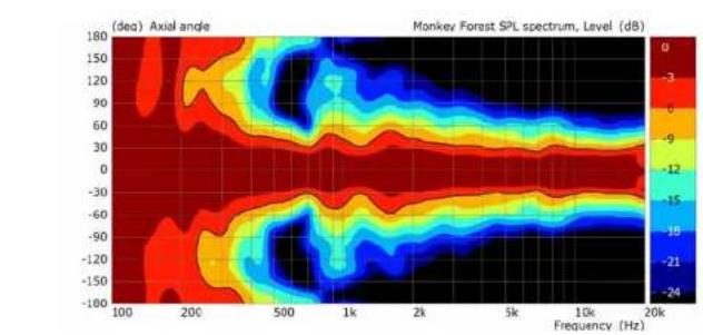
heatmap
| Frequency (Hz) | Axial angle (deg) | Level (dB) | | -------------- | ----------------- | ---------- | | 100 | -180 | 0 | | 100 | -120 | -3 | | 100 | -90 | -6 | | 100 | -60 | -9 | | 100 | -30 | -12 | | 100 | 0 | -15 | | 100 | 30 | -18 | | 100 | 60 | -21 | | 100 | 90 | -24 | | 100 | 120 | -24 | | 100 | 150 | -24 | | 100 | 180 | -24 | | 200 | -180 | 0 | | 200 | -120 | -3 | | 200 | -90 | -6 | | 200 | -60 | -9 | | 200 | -30 | -12 | | 200 | 0 | -15 | | 200 | 30 | -18 | | 200 | 60 | -21 | | 200 | 90 | -24 | | 200 | 120 | -24 | | 200 | 150 | -24 | | 200 | 180 | -24 | | 500 | -180 | 0 | | 500 | -120 | -3 | | 500 | -90 | -6 | | 500 | -60 | -9 | | 500 | -30 | -12 | | 500 | 0 | -15 | | 500 | 30 | -18 | | 500 | 60 | -21 | | 500 | 90 | -24 | | 500 | 120 | -24 | | 500 | 150 | -24 | | 500 | 180 | -24 | | 1k | -180 | 0 | | 1k | -120 | -3 | | 1k | -90 | -6 | | 1k | -60 | -9 | | 1k | -30 | -12 | | 1k | 0 | -15 | | 1k | 30 | -18 | | 1k | 60 | -21 | | 1k | 90 | -24 | | 1k | 120 | -24 | | 1k | 150 | -24 | | 1k | 180 | -24 | | 2k | -180 | 0 | | 2k | -120 | -3 | | 2k | -90 | -6 | | 2k | -60 | -9 | | 2k | -30 | -12 | | 2k | 0 | -15 | | 2k | 30 | -18 | | 2k | 60 | -21 | | 2k | 90 | -24 | | 2k | 120 | -24 | | 2k | 150 | -24 | | 2k | 180 | -24 | | 5k | -180 | 0 | | 5k | -120 | -3 | | 5k | -90 | -6 | | 5k | -60 | -9 | | 5k | -30 | -12 | | 5k | 0 | -15 | | 5k | 30 | -18 | | 5k | 60 | -21 | | 5k | 90 | -24 | | 5k | 120 | -24 | | 5k | 150 | -24 | | 5k | 180 | -24 | | 10k | -180 | 0 | | 10k | -120 | -3 | | 10k | -90 | -6 | | 10k | -60 | -9 | | 10k | -30 | -12 | | 10k | 0 | -15 | | 10k | 30 | -18 | | 10k | 60 | -21 | | 10k | 90 | -24 | | 10k | 120 | -24 | | 10k | 150 | -24 | | 10k | 180 | -24 | | 20k | -180 | 0 | | 20k | -120 | -3 | | 20k | -90 | -6 | | 20k | -60 | -9 | | 20k | -30 | -12 | | 20k | 0 | -15 | | 20k | 30 | -18 | | 20k | 60 | -21 | | 20k | 90 | -24 | | 20k | 120 | -24 | | 20k | 150 | -24 | | 20k | 180 | -24 |Horizontal directivity 60°

heatmap
| Frequency (Hz) | Axial angle (deg) | Monkey Forest SPL Spectrum Level (dB) | | -------------- | ----------------- | ------------------------------------- | | 100 | -180 | -24 | | 200 | -150 | -21 | | 500 | -90 | -18 | | 1k | -60 | -15 | | 2k | -30 | -12 | | 5k | 0 | -9 | | 10k | 30 | -6 | | 20k | 60 | -3 | | 50k | 90 | 0 | | 100k | 120 | 3 | | 200k | 150 | 6 | | 500k | 180 | 9 | | 1k | 150 | 12 | | 2k | 120 | 15 | | 5k | 90 | 18 | | 10k | 60 | 21 | | 20k | 30 | 24 |Horizontal directivity 80°

heatmap
| Frequency (Hz) | Axial angle (deg) | Sound pressure (dB) | | -------------- | ----------------- | ------------------- | | 100 | 180 | 0 | | 200 | 150 | -3 | | 500 | 120 | -6 | | 1k | 90 | -9 | | 2k | 60 | -12 | | 5k | 30 | -15 | | 10k | 0 | -18 | | 20k | -30 | -21 | | 500 | -60 | -24 | | 1k | -90 | -24 | | 2k | -120 | -24 | | 5k | -150 | -24 | | 10k | -180 | -24 |Vertical directivity (three C 8s at 0° splay)

line
| Frequency (Hz) | IFC: C10 - 3x06 - 3% THD | IFC: C10 - 3x06 - 10% THD | | -------------- | ------------------------ | ------------------------- | | 20 | 100 | 100 | | 50 | 125 | 125 | | 100 | 120 | 128 | | 200 | 130 | 135 | | 500 | 135 | 140 | | 1K | 130 | 145 | | 2K | 125 | 135 | | 5K | 120 | 130 | | 10K | 120 | 130 | | 20K | 120 | 130 |Max. SPL (blue=3% THD, red=10% THD)

heatmap
| Frequency (Hz) | Axial angle (deg) | Sound pressure, Level (dB) | | -------------- | ----------------- | -------------------------- | | 100 | -180 | -24 | | 100 | -150 | -21 | | 100 | -90 | -18 | | 100 | -60 | -15 | | 100 | -30 | -12 | | 100 | 0 | -9 | | 100 | 30 | -6 | | 100 | 60 | -3 | | 100 | 90 | 0 | | 200 | -180 | -24 | | 200 | -150 | -21 | | 200 | -90 | -18 | | 200 | -60 | -15 | | 200 | -30 | -12 | | 200 | 0 | -9 | | 200 | 30 | -6 | | 200 | 60 | -3 | | 200 | 90 | 0 | | 500 | -180 | -24 | | 500 | -150 | -21 | | 500 | -90 | -18 | | 500 | -60 | -15 | | 500 | -30 | -12 | | 500 | 0 | -9 | | 500 | 30 | -6 | | 500 | 60 | -3 | | 500 | 90 | 0 | | 1k | -180 | -24 | | 1k | -150 | -21 | | 1k | -90 | -18 | | 1k | -60 | -15 | | 1k | -30 | -12 | | 1k | 0 | -9 | | 1k | 30 | -6 | | 1k | 60 | -3 | | 1k | 90 | 0 | | 2k | -180 | -24 | | 2k | -150 | -21 | | 2k | -90 | -18 | | 2k | -60 | -15 | | 2k | -30 | -12 | | 2k | 0 | -9 | | 2k | 30 | -6 | | 2k | 60 | -3 | | 2k | 90 | 0 | | 5k | -180 | -24 | | 5k | -150 | -21 | | 5k | -90 | -18 | | 5k | -60 | -15 | | 5k | -30 | -12 | | 5k | 0 | -9 | | 5k | 30 | -6 | | 5k | 60 | -3 | | 5k | 90 | 0 | | 10k | -180 | -24 | | 10k | -150 | -21 | | 10k | -90 | -18 | | 10k | -60 | -15 | | 10k | -30 | -12 | | 10k | 0 | -9 | | 10k | 30 | -6 | | 10k | 60 | -3 | | 10k | 90 | 0 | | 20k | -180 | -24 | | 20k | -150 | -21 | | 20k | -90 | -18 | | 20k | -60 | -15 | | 20k | -30 | -12 | | 20k | 0 | -9 | | 20k | 30 | -6 | | 20k | 60 | -3 | | 20k | 90 | 0 | | +∞ | +∞ | +∞ | The chart displays the frequency (Hz) on the x-axis and the axial angle (deg) on the y-axis. The color scale indicates the level of sound pressure in dB. There are no labels for the data series.Vertical directivity (three C 8s at 3° splay)


natural_image
Technical line drawing of a rectangular electronic device with two internal components and a 475 mm dimension label (no text or symbols beyond the dimension)4 CF 118 subwoofer
CF 118 - Technical specifications
| Power handling, nominal RMS 1600 W | |
| Power handling, program 3200 W | |
| Frequency response +/-3 dB 35 Hz - | 120 Hz |
| Frequency response - 10 dB 32 Hz - | 120 Hz |
| Sensitivity 1 W @ 1 m 93 dB (40 Hz - | 120 Hz), full space |
| Max. SPL @ 10 % THD(EN 50268-21:2019) | 129 dB |
| Electrical impedance 8 ohms | |
| LF Speaker 1x 18", 4" voice coil | |
| Connections 4x Speakon NL4 (with sealing cap), 2 each front and rear, pinassignment switch | |
| Integrated pole mount 1x M20 | |
| Rigging points 4-point rigging hardware with black KTL coating | |
| Carrying handles 4x MultiCrip | |
| Housing | Birch Multiplex |
| Finish | PU coating, black |
| Front grille | Steel front grille with anticorrosive coating, backed withacoustic foam |
| Dimensions (W x H x D) | 60 x 63,5 x 78.5 cm23-5/8 x 25 x 30-29/32" |
| Weight | 54.8 kg/ 120.8 lbs |

line
| Frequency (Hz) | MaxSPL (dB) | | -------------- | ----------- | | 20 | 83 | | 25 | 90 | | 30 | 105 | | 35 | 115 | | 40 | 118 | | 45 | 120 | | 50 | 121 | | 55 | 121 | | 60 | 121 | | 65 | 121 | | 70 | 120 | | 75 | 120 | | 80 | 120 | | 85 | 118 | | 90 | 118 | | 95 | 118 | | 100 | 118 | | 105 | 118 | | 110 | 118 | | 115 | 118 | | 120 | 118 | | 125 | 118 | | 130 | 118 | | 135 | 118 | | 140 | 118 | | 145 | 118 | | 150 | 118 | | 155 | 118 | | 160 | 118 | | 165 | 118 | | 170 | 118 | | 175 | 118 | | 180 | 118 | | 185 | 118 | | 190 | 118 | | 195 | 118 | | 200 | 120 |Max. SPL (blue - 3% THD, red - 10% THD)


natural_image
Pure technical line drawing of a rectangular frame with two internal square components and mounting holes (no text or symbols)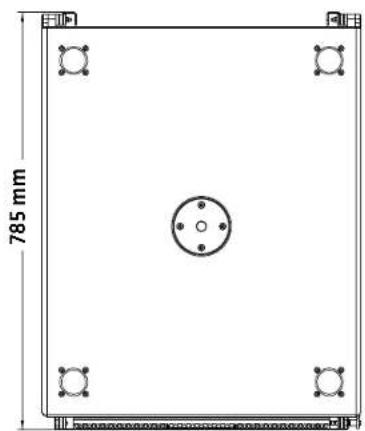
5 CS 118 subwoofer
CS 118 - Technical specifications
| Power handling, nominal RMS 1600 W | |
| Power handling, program 3200 W | |
| Frequency response +/-3 dB 35 Hz - 120 Hz | |
| Frequency response - 10 dB 31 Hz - 120 Hz | |
| Sensitivity 1 W @ 1 m 93 dB (40 Hz - 120 Hz), full space | |
| Max. SPL @ 10 % THD(EN 50268-21:2019) | 129 dB |
| Electrical impedance 8 ohms | |
| LF Speaker 1x 18", 4" voice coil | |
| Connections 4x Speakon NL4 (with sealing cap), 2 each front and rear, pin assignment switch | |
| Integrated pole mount 1x M20 | |
| Rigging points - | |
| Carrying handles 4x MultiCrip | |
| Housing | Birch Multiplex |
| Finish | PU coating, black |
| Front grille | Steel front grille with anticorrosive coating, backed with acoustic foam |
| Dimensions (W x H x D) | 60 x 61 x 78 cm23-5/8 x 24-5/32 x 30-23/32" |
| Weight | 47.5 kg / 105.0 lbs |

line
| Frequency (Hz) | MaxSPL (dB) | | -------------- | ----------- | | 20 | 83 | | 25 | 90 | | 30 | 105 | | 35 | 115 | | 40 | 118 | | 45 | 120 | | 50 | 121 | | 55 | 121 | | 60 | 121 | | 65 | 121 | | 70 | 120 | | 75 | 120 | | 80 | 120 | | 85 | 118 | | 90 | 118 | | 95 | 118 | | 100 | 118 | | 105 | 118 | | 110 | 118 | | 115 | 118 | | 120 | 118 | | 125 | 118 | | 130 | 118 | | 135 | 118 | | 140 | 118 | | 145 | 118 | | 150 | 118 | | 155 | 118 | | 160 | 118 | | 165 | 118 | | 170 | 118 | | 175 | 118 | | 180 | 118 | | 185 | 118 | | 190 | 118 | | 195 | 118 | | 200 | 120 |Max. SPL (blue - 3% THD, red - 10% THD)
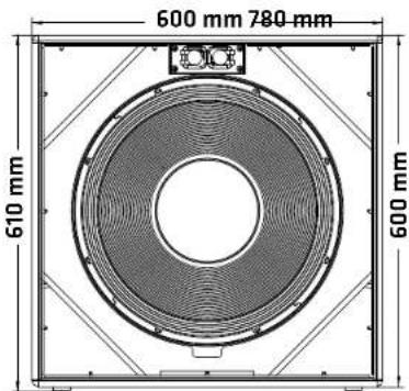
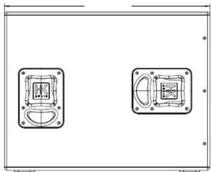
natural_image
Technical line drawing of a two-part electronic device panel with mounting holes and internal components (no text or symbols)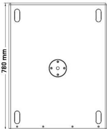
natural_image
Pure technical diagram of a rectangular frame with rounded corners and a central circular feature, dimensioned as 780 mm (no text or symbols beyond measurement lines)6 CS 218 subwoofer
CS 218 - Technical specifications
| Power handling, nominal RMS 3200 W | |
| Power handling, program 6400 W | |
| Frequency response +/-3 dB 27 Hz - | 100 Hz |
| Frequency response - 10 dB 23 Hz - | 100 Hz |
| Sensitivity 1 W @ 1 m 94 dB (30 Hz - | 100 Hz), full space |
| Max. SPL @ 10 % THD(EN 50268-21:2019) | 133 dB |
| Electrical impedance 4 ohms | |
| LF Speaker 2x 18", 4" voice coil | |
| Connections 4x Speakon NL4 (with sealing cap), 2 each front and rear, pin assignment switch | |
| Integrated pole mount 2x M20 | |
| Rigging points - | |
| Carrying handles | 8x MultiGrip |
| Housing | Birch Multiplex |
| Finish | PU coating, black |
| Front grille | Steel front grille with anticorrosive coating, backed with acoustic foam |
| Dimensions (W x H x D) | 121 x 61 x 78 t47-41/64 x 24-5/32 x 30-23/32" |
| Weight | 88.0 kg / 194.0 lbs |

line
| Frequency (Hz) | MaxSPL (dB) | | -------------- | ----------- | | 20 | 95 | | 30 | 115 | | 40 | 125 | | 50 | 125 | | 60 | 125 | | 70 | 125 | | 80 | 125 | | 90 | 125 | | 100 | 125 | | 110 | 125 | | 120 | 125 | | 130 | 125 | | 140 | 125 | | 150 | 125 | | 160 | 125 | | 170 | 125 | | 180 | 125 | | 190 | 125 | | 200 | 125 |Max. SPL (blue - 3% THD, red - 10% THD)

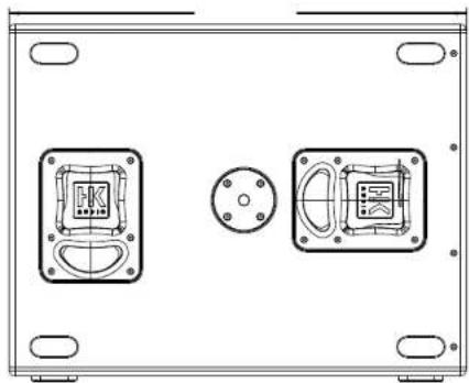
natural_image
Technical line drawing of a mechanical component with two square flanges and central circular features (no text or symbols)
natural_image
Technical diagram of a rectangular enclosure with two internal components and mounting holes, dimensioned as 780 mm (no text or symbols)7 PB-8 patchbay
PB-8 - Technical specifications
| Dimensions (W x H x D) 48.5 x 8.8 x 11.5 cm19-15/16 x 3-11/32 x 4-17/32" |
| Weight 4.2 kg / 9.3 lbs |

The PB-8's internal wiring

flowchart
graph TD
    A["Speaker NL4 Channel 1+2 to Amp CH1+2"] --> B["1st pair"]
    C["Speaker NL4 Channel 3+4 to Amp CH3+4"] --> D["2nd pair"]
    B --> E["Ch1 1/2"]
    D --> F["Ch2 1/2"]
    E --> G["CH 1/2"]
    F --> H["CH 2/2"]
    G --> I["Ch1 2/2"]
    H --> J["Ch2 2/2"]
    I --> K["Ch3 2/2"]
    J --> L["Ch4 2/2"]
    K --> M["Ch5 2/2"]
    L --> N["Ch6 2/2"]
    M --> O["Ch7 2/2"]
    N --> P["Ch8 2/2"]
    O --> Q["Ch9 2/2"]
    P --> R["Ch10 2/2"]
    Q --> S["Ch11 2/2"]
    R --> T["Ch12 2/2"]
    S --> U["Ch13 2/2"]
    T --> V["Ch14 2/2"]
    U --> W["Ch15 2/2"]
    V --> X["Ch16 2/2"]
    W --> Y["Ch17 2/2"]
    X --> Z["Ch18 2/2"]
    Y --> AA["Ch19 2/2"]
    Z --> AB["Ch20 2/2"]
    AA --> AC["Ch21 2/2"]
    AB --> AD["Ch22 2/2"]
    AC --> AE["Ch23 2/2"]
    AD --> AF["Ch24 2/2"]
    AE --> AG["Ch25 2/2"]
    AF --> AH["Ch26 2/2"]
    AG --> AI["Ch27 2/2"]
    AH --> AJ["Ch28 2/2"]
    AI --> AK["Ch29 2/2"]
    AJ --> AL["Ch30 2/2"]
    AK --> AM["Ch31 2/2"]
    AL --> AN["Ch32 2/2"]
    AM --> AO["Ch33 2/2"]
    AN --> AP["Ch34 2/2"]
    AO --> AQ["Ch35 2/2"]
    AP --> AR["Ch36 2/2"]
    AQ --> AS["Ch37 2/2"]
    AR --> AT["Ch38 2/2"]
    AS --> AU["Ch39 2/2"]
    AT --> AV["Ch40 2/2"]
    AU --> AW["Ch41 2/2"]
    AV --> AX["Ch42 2/2"]
    AW --> AY["Ch43 2/2"]
    AX --> AZ["Ch44 2/2"]
    AY --> BA["Ch45 2/2"]
    AZ --> BB["Ch46 2/2"]
8 Declarations of conformity

Slamar B, Microbank, C-10
Magdamer Str. 2.65605 St. Wendel
1

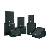
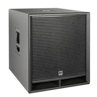
- Instructions for use Original edition
- COSMO
- Operating Instructions 2.0
- Welcome to the HK Audio family!
- Your HK Audio team
- Warranty
- HK Audio
- Important Notes on Safety and Use! Please read before connecting the system!
- Introduction
- COSMO - Modular for Economy and Flexibility
- COSMO Components at a Glance
- Speaker cabinets
- Amps and controllers
- Speaker cables
- Rigging, hardware, transport
- Software
- Components
- Speaker Cabinets
- LSM
- LSM Mid/High
- LSM Sub
- Rigging and Transport Hardware
- Software
- EASE Focus 3
- EASE 4.4
- Lake
- Armonía
- Connectors and Speaker Cables
- • CF 118, CS 118, CS 218 subwoofers
- Four speaker outputs are at your disposal:
- Connecting COSMO M/H units
- Connecting subwoofers
- Using the COSMO multicore cable
- Controller Settings
- Recommended filters
- Example Setups
- Rigging Manual 2.0
- Notes on Rigging Safety
- - Rigging hardware
- - Prerequisites for installing the COSMO Line Array
- • Curving in compressed mode
- - Safe application
- - Speaker stands
- - Ground stacks
- - Improper use
- Never
- Serious dangers associated with improper use include:
- Do not move the system over people.
- • Inspection and maintenance
- • Disassembly
- • Hearing protection
- Planning Arrays
- Acoustic modeling with EASE Focus 3
- Mechanical limits
- - Scenarios to determine limits as calculated by a structural engineer
- Scenarios to determine mechanical limits
- Intended Use
- • Rigging and curving
- Use
- - Intended use
- • Warranty and liability
- Storage, maintenance, inspection and repair of rigging hardware
- • Storage and safekeeping when not in use
- - Maintenance
- - Cleaning
- - Repair
- Technical specification for COSMO rigging hardware
- - Working load limits
- • Maximum number of flown M/H units
- - Modifications to COSMO rigging hardware
- • Original HK Audio accessories
- Rigging Hardware
- CRF-80 COSMO rigging frame
- CRF-60 COSMO rigging frame
- CRF-PB pull-back frame
- C-PPA pick-point adapter
- C-M20 adapter
- C-GSA ground stack adapter
- C-STR tensioning strap (not shown)
- Connecting Hardware and Curving Arrays
- General information on connections
- Flown arrays
- Transport
- In ground stacks
- Compressed mode vs. fixed mode
- Curving in Compressed Mode
- The following instructions and illustrations apply to both the CRF-60 and CRF-80.
- Curving in Fixed Mode
- Setting Up a CF 118 Array
- Setting Up Ground Stacks
- Stacking speakers on top of a CS 118/CS 218 with the rigging frame only (+2°/0°/-2°)
- Stacking speakers on top of a CS 118/CS 218 with the rigging frame and the C-GSA ground stack adapter (-6° to -20°)
- Example tilt angles:
- Stacking speakers on top of a CF 118 with a CRF-80 rigging frame
- Stacking speakers on top of a subwoofer with the CRF-PB pull-back frame
- Disassembling Flown Arrays
- Disassembling a compressed array
- Disassembling a fixed array
- Appendix 2.0
- C 6 mid/high unit
- C 6 - Technical specifications
- C 8 mid/high unit
- C 10 mid/high unit
- CF 118 subwoofer
- CS 118 subwoofer
- CS 218 subwoofer
- PB-8 patchbay
- Declarations of conformity
Brand : HK AUDIO
Model : Cosmo
Category : Speaker