
DE-945CD - Computer case AOPEN - Free user manual and instructions
Find the device manual for free DE-945CD AOPEN in PDF.


| Product Type | Digital Engine / Mini PC |
| Brand | AOpen |
| Model | DE-945CD |
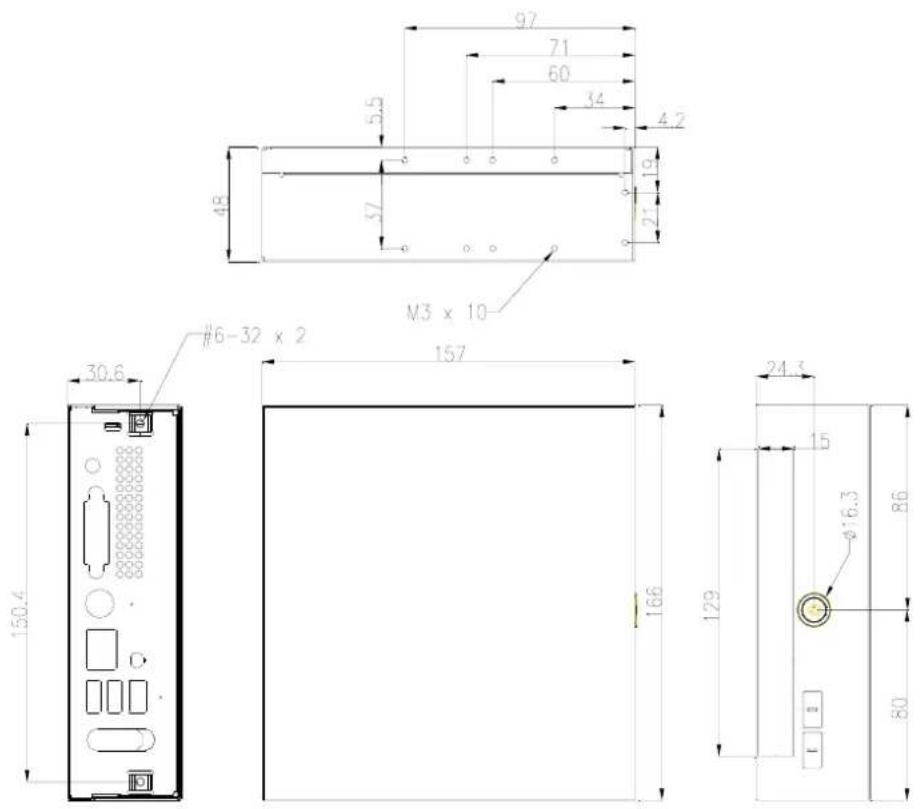
| Dimensions (approx.) | 166 x 150.4 x 60 mm (based on DE945-FX diagram) |
| Weight (approx.) | 1.5 kg |
| Power Supply | External AC adapter, 100-240V, 50/60Hz |
| CPU Socket | Socket for Intel processor (specific type not specified) |
| Memory | 1 x DIMM slot (likely DDR2) |
| Storage | 1 x 2.5" SATA or P-ATA HDD |
| Optical Drive | 1 x Slim ODD (optional) |
| Mounting Options | VESA (100x100mm, 75x75mm), L-type bracket, vertical stand |
| Front I/O | USB ports, power switch |
| Internal Card | Internal card for additional connections (e.g., USB, data) |
| Cooling | Active cooler with fan |
| Material | Metal casing |
| Color | Black |
| Operating Temperature | 0-40°C (estimate) |
| Certifications | CE, FCC (assumed) |
| Included Accessories | Mounting brackets, screws, AC adapter |
Frequently Asked Questions - DE-945CD AOPEN
User questions about DE-945CD AOPEN
0 question about this device. Answer the ones you know or ask your own.
Ask a new question about this device
Download the instructions for your Computer case in PDF format for free! Find your manual DE-945CD - AOPEN and take your electronic device back in hand. On this page are published all the documents necessary for the use of your device. DE-945CD by AOPEN.
USER MANUAL DE-945CD AOPEN
Assembly Guide for DE-945
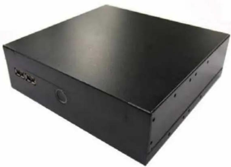
natural_image
Black rectangular electronic device casing with mounting holes and a circular button (no visible text or symbols)V1.0
2007/06/11
Index
- OPEN HOUSING.... 2
- INSTALL KEY COMPONENTS...... 4
- ASSEMBLE THE SUPPORTER & UPPER CASE .... 14
APPENDIX 3 KINDS HOLDER....21
1. Open Housing
1-1.
Unscrew the upper case (2@M3 screws in rear side)

1-2.
Remove the Upper case
Front Side

natural_image
Black rectangular object with a red upward arrow on the left side, no visible text or symbols.Rear Side
1-3. Unscrew 4@M3 screws from supporter bracket
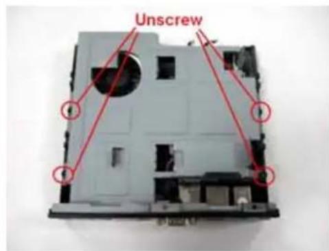
1-4. Remove Supporter

natural_image
Hand holding a CD-ROM drive with visible internal components and a red curved arrow indicating rotation (no text or symbols)1-5. You will see the kernel of Digital Engine

natural_image
Interior view of an open computer case showing internal circuit board and fan (no visible text or symbols)2. Install Key components
2-1 Install Memory and CPU
2-1-1.
Insert the memory on the socket as this angle.

2-1-2.
Then press the Dimm as flat on the Motherboard, and you will hear the click voice.

2-1-3. Unscrew the CPU cooler

2-1-5. Unscrew CPU socket counterclockwise
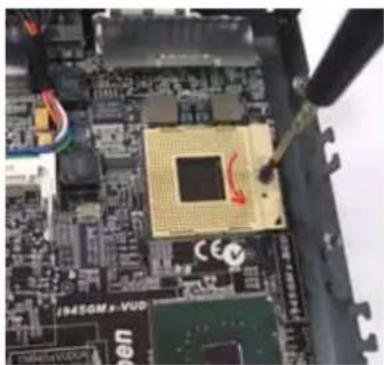
natural_image
Close-up of a computer motherboard with visible CPU socket and wiring (no readable text or symbols)2-1-4. Remove the cooler

natural_image
Close-up of a computer motherboard with a hand inserting a component (no visible text or symbols)2-1-6 Put the CPU into the socket, and check the direction.

natural_image
Close-up of a computer motherboard with visible CPU socket and surrounding components (no readable text or symbols)2-1-8. Put on the cooler and screw it tightly. clockwise

2-1-7. Screw the CPU socket.

natural_image
Close-up of a computer motherboard with visible CPU socket and circuitry (no readable text or symbols)2-1-9 connect the wire for cooler

natural_image
Close-up of an open computer motherboard showing a CPU socket, heatsink, and wiring (no visible text or symbols)2-3 Fix HDD on Supporter (without ODD)
2-3-1 Screw HDD with 4@M3 screw (on both flanks)

natural_image
Exterior view of a gray hard drive housing with red arrows pointing to components (no readable text or symbols)

2-3-2 Fix the Card Holder
Put the Card Holder on the supporter,

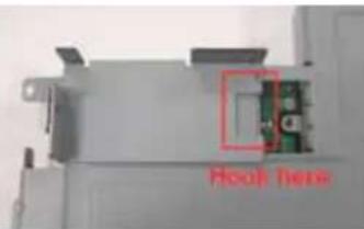
and screw it with 1@M2 screw.

natural_image
Close-up of a mechanical component with a metallic rod inserted, showing internal structure (no visible text or symbols)2-4 Fix HDD on Supporter (with ODD)
2-4-1 Put the HDD on support and screw HDD with 4@M3 screw (on both flanks)

natural_image
Two hard disk components with red arrows pointing to each, one showing internal features and the other a green logo (no readable text or symbols)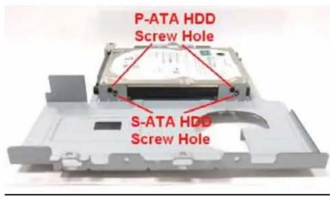

2-4-2 Put slim ODD on the other side of supporter, screw the position 1 and 2 with M2 screw first, then screw position 3 and with M2 screw to fix the slim ODD.
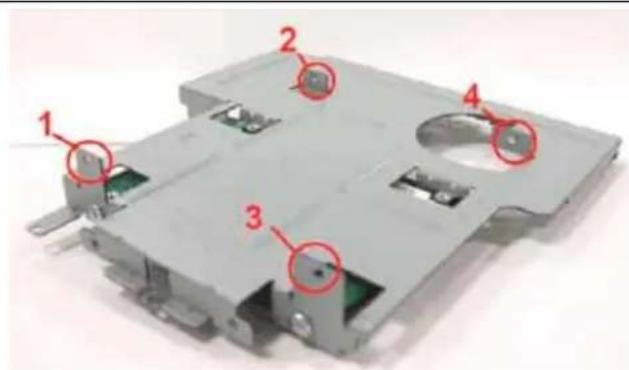

natural_image
Exterior view of a battery pack assembly with numbered components (no visible text or symbols)
2-5.Fix the Internal Card without ODD
2-5-1. Insert the Internal Card into HDD

2-5-2 Screw internal card to Card holder with 2@M2 screws.

2-6. Fix the Internal Card with ODD
2-6-1. Insert the Internal Card into HDD and ODD

2-6-2 Screw internal card to ODD with 2 M2 screws.
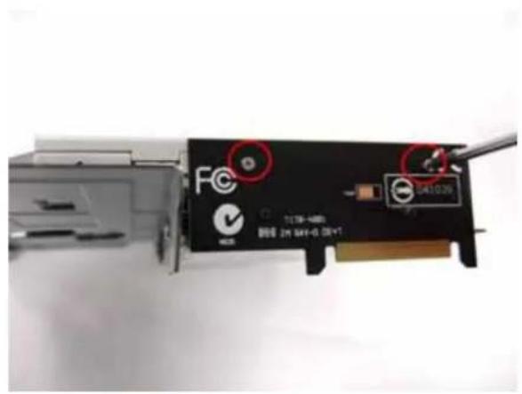
3. Assemble the Supporter & Upper Case
3-1. Make sure Front USB wire connect to MB
Model: DE-945BCD/CD
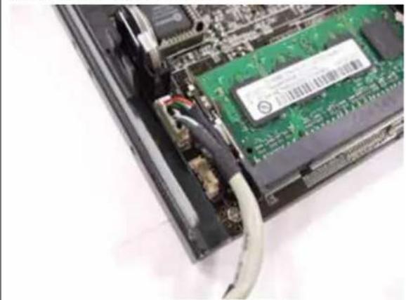
natural_image
Close-up of an electronic circuit board with visible internal components and a cable inserted (no text or symbols)Model: DE-945FX

3-2. Fix the supporter (Only HDD is on the supporter now)
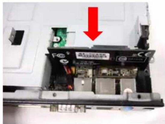
3-2-1. Make sure the internal card is correctly insert into the socket
natural_image
Interior view of a printer's internal circuit board with a red arrow pointing to a component (no visible text or symbols)
natural_image
Interior view of an electronic device showing internal components and a highlighted section (no readable text or symbols)3-2-2.Screw 4@M3 screw at the supporter.

natural_image
Interior view of a computer case with visible circuit boards and components, marked with red circles (no text or symbols)3-3. Fix the supporter (HDD and ODD are on the supporter now)
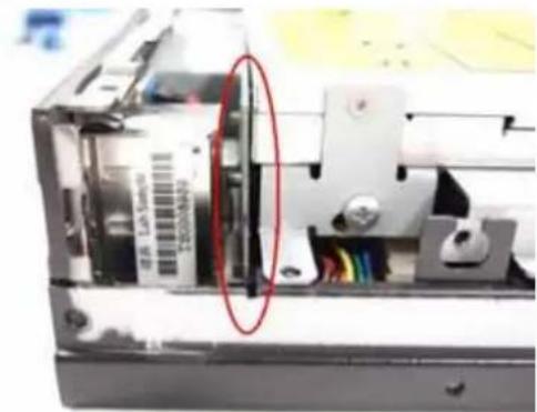
3-3-1. Make sure the internal card is correctly insert into the socket

natural_image
Close-up of an electronic device showing internal components and a red-circled highlight (no readable text or symbols)3-3-2.Screw 4@M3 screw at the supporter.

3-4. Assemble the upper case (without ODD)
3-3-1. Connect the power switch wire.

natural_image
Close-up of a computer motherboard showing a CPU socket connected to a cable with visible wiring and a fan (no text or symbols)3-3-2. Connect the Front-USB wire to upper\_case.

natural_image
Close-up of hands installing a green circuit board component with two red circles highlighting the pins (no text or symbols visible)3-5 Assemble the upper case (with ODD)
3-5-1. Remove ODD door on upper case

natural_image
Two black electronic devices with ports and a tool inserted, no visible text or symbols3-5-2. Connect the power switch wire.

natural_image
Close-up of electronic components with colored wires and a green circuit board (no visible text or symbols)3-5-3. Connect the Front-USB wire to upper\_case.

natural_image
Close-up of hands installing a green circuit board with two circular annotations highlighting the components (no readable text or symbols)3-6.Screw the upper case
1

natural_image
Close-up of hands installing or removing a physical electronic device into a computer case (no visible text or symbols)3 Screw 2@M3 screw at rear side

natural_image
Back view of a black computer drive with ports and connectors, showing a cable inserted into the rear panel (no text or symbols visible)2

natural_image
Black electronic device with a red arrow pointing left, no visible text or symbols
natural_image
Black electronic device casing with a red arrow pointing left, no visible text or symbolsWith ODD

natural_image
Black hard drive with open rear panel and drive button (no visible text or symbols)Without ODD
natural_image
Black rectangular electronic device with ports and a button (no visible text or symbols)Appendix 3 kinds holder
A. L type Holder(Include 2 piece holder and 8 screws)
A-1
L type Holder is a versatile holder, you can screw it on any place you want.

natural_image
Black rectangular electronic device with mounting bracket and metal bracket (no visible text or symbols)A-2
You can put on the L type Holder on 2 sides, and screw it tightly.

natural_image
Black rectangular electronic device with ports and a small button, placed on a plain surface (no visible text or symbols)A-3 Dimension of L type Holder. (unit: mm)

B. Monitor Holder (Include 2 piece holder and 8 screws)
B-1
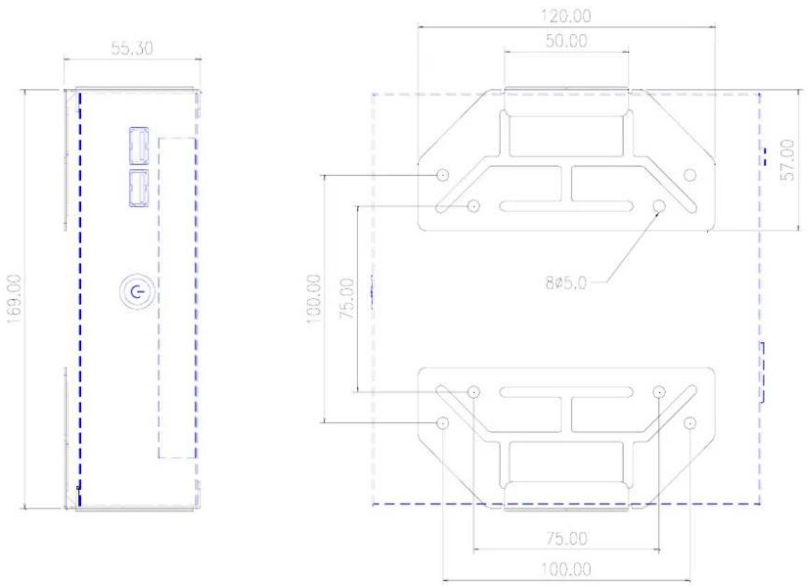
Monitor Holder is base on VESA standard (10cm/7.5cm interval) for you to screw the Digital Engine behind the monitor.

natural_image
Black electronic device with attached metal bracket and mounting bracket (no visible text or symbols)B-2
You can put on the Holder on 2 sides, and screw it tightly.

natural_image
Black rectangular electronic device with a flat top and side connectors, placed on a plain white surface (no visible text or symbols)B-3 Dimension of Monitor Holder (unit: mm)
C. Vertical Holder (Include 2 piece holder and 8 screws)
C-1
You can put the Digital Engine Vertical with the holder

natural_image
Black metal bracket with four mounting holes and a rectangular electronic box in the background (no visible text or symbols)C-2
You can put the stand(s) on right side, and screw it tightly.

natural_image
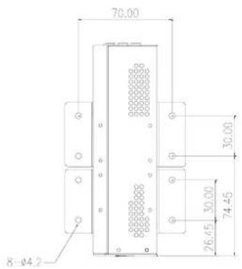
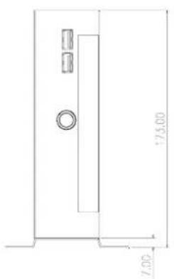
Close-up of a black metal bracket with two black mounting feet, no visible text or symbolsC-3 Dimension of Vertical Holder. (Single Stand) (unit: mm)


natural_image
Empty white square with a small rectangular border at the bottom (no text or symbols)C-4 Dimension of Vertical Holder.(Double Stand) (unit: mm)

natural_image
Blank white rectangular frame with no text, numbers, or symbolsD. Dimension of DE945-FX (unit: mm)
- Assembly Guide for DE-945
- Index
- Open Housing
- 1-1.
- 1-2.
- Install Key components
- 2-1 Install Memory and CPU
- 2-1-1.
- 2-1-2.
- 2-3 Fix HDD on Supporter (without ODD)
- 2-3-2 Fix the Card Holder
- 2-4 Fix HDD on Supporter (with ODD)
- 2-5.Fix the Internal Card without ODD
- 2-5-1. Insert the Internal Card into HDD
- 2-5-2 Screw internal card to Card holder with 2@M2 screws.
- 2-6. Fix the Internal Card with ODD
- Assemble the Supporter & Upper Case
- 3-1. Make sure Front USB wire connect to MB
- 3-2. Fix the supporter (Only HDD is on the supporter now)
- 3-2-1. Make sure the internal card is correctly insert into the socket
- 3-2-2.Screw 4@M3 screw at the supporter.
- 3-3. Fix the supporter (HDD and ODD are on the supporter now)
- 3-3-1. Make sure the internal card is correctly insert into the socket
- 3-3-2.Screw 4@M3 screw at the supporter.
- 3-4. Assemble the upper case (without ODD)
- 3-3-1. Connect the power switch wire.
- 3-3-2. Connect the Front-USB wire to upper\_case.
- 3-5 Assemble the upper case (with ODD)
- 3-5-1. Remove ODD door on upper case
- 3-5-2. Connect the power switch wire.
- 3-5-3. Connect the Front-USB wire to upper\_case.
- 3-6.Screw the upper case
- Appendix 3 kinds holder
- A-1
- A-2
- B-1
- B-2
- C-1
- C-2
Brand : AOPEN
Model : DE-945CD
Category : Computer case