
DEX4502 - Industrial computer AOPEN - Free user manual and instructions
Find the device manual for free DEX4502 AOPEN in PDF.


| Type de produit | LCD Monitor |
| Marque | AOpen |
| Modèle | DEX4502 |
| Taille de l'écran | 24 inches (diagonal) |
| Résolution | 1920 x 1080 (Full HD) |
| Taux de rafraîchissement | 60 Hz |
| Format d'image | 16:9 |
| Luminosité | 250 cd/m² |
| Taux de contraste | 1000:1 |
| Temps de réponse | 5 ms |
| Connectivité | VGA, HDMI 1.4, DisplayPort 1.2 |
| Consommation électrique (typique) | 30 W |
| Consommation en veille | < 0.5 W |
| Poids (avec pied) | 4.5 kg |
| Dimensions (avec pied) LxHxP | 550 x 400 x 200 mm |
| Fixation VESA | 100 x 100 mm |
| Fonctions principales | Flicker-free, Blue light filter, Tilt adjustment |
| Entretien et nettoyage | Use a soft dry cloth; do not use liquids or abrasives |
| Sécurité | Use a grounded outlet; do not block ventilation slots |
| Pièces détachées et réparabilité | Power cable included; not user-serviceable; contact AOpen support |
| Informations générales | 50-page manual available for download |
Frequently Asked Questions - DEX4502 AOPEN
User questions about DEX4502 AOPEN
0 question about this device. Answer the ones you know or ask your own.
Ask a new question about this device
Download the instructions for your Industrial computer in PDF format for free! Find your manual DEX4502 - AOPEN and take your electronic device back in hand. On this page are published all the documents necessary for the use of your device. DEX4502 by AOPEN.
USER MANUAL DEX4502 AOPEN
Assembly Guide for DEX4500 series

natural_image
Front view of a black server rack with three ports and ventilation slots (no visible text or labels)V2.0
2008/12/17
Index
- Outlook ......2
- Install Key components ( Except Mini card module installation)......4
- Install Key components ( Including Mini card module installation)...16
- Connector & PINs definitions....39
- Appendix 1 Packing List....41
- Appendix 2 Table of Screw and Torque....42
- Appendix 3 Watch Dog Timer Configuration....43
- Appendix 4 Outline Drawing....48
1. Outlook
Front IO

Rear IO
Antenna Hole

2. Install Key components (Except Mini card module installation)
2-1.
Loosen 2 pcs of front panel screw (FPH M3 screw) by the screw driver and remove it.

natural_image
Back panel of a black electronic device with three ports and two red circular annotations pointing to the left port (no text or symbols on the device itself)Unscrew 2 x FPH M3 screw
2-2.
Loosen 4 pcs of Top cover screw (FPH M3 screw) by the screw driver and remove it.

natural_image
Close-up of a black rectangular electronic component with red annotation arrows pointing to specific areas (no text or symbols visible)Unscrew 4 x M3 screw
2-3.
You will see the kernel of Digital Engine.
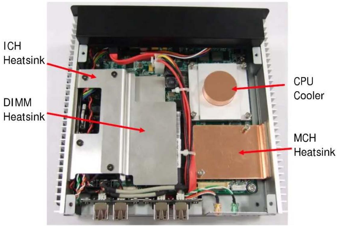
2-4 Install Memory
2-4-1.
Loosen 2 pcs of DIMM heatsink screw (FPH M3 screw) by the screw driver and remove it.

2-4-2.
Insert the memory on the upper socket as this angle.

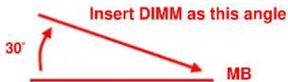
2-4-3. 2-4-4.
Then press the DIMM as flat on the Motherboard, and you will hear the click voice.
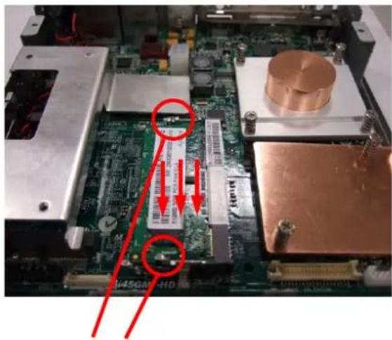
Make sure it clicks
Take off the protect Mylar of thermal pad of DIMM heatsink and place it back to ICH heatsink.

natural_image
Metal L-shaped object with red and gray colored blocks, no visible text or symbols2-4-5.
Screw it tightly with 2 pcs of FPH M3 screws by the screw driver
(Screwdriver torque : 3.0 ±0.5 kgf. cm )
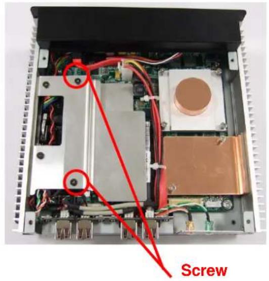
2-5 Install CPU
2-5-1.
Loosen 4 pcs of CPU cooler screw by the screw driver and remove it.

2-5-2.
Unlock the CPU socket screw Counterclockwise
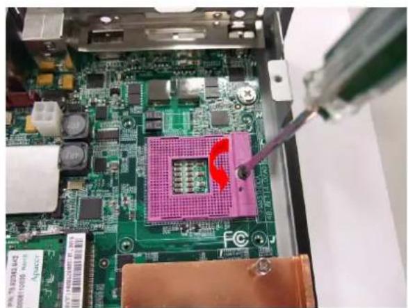
natural_image
Close-up of a green circuit board with a pink CPU socket and soldering tool inserted, no visible text or symbols2-5-3
Put the CPU into the socket, and check the direction.
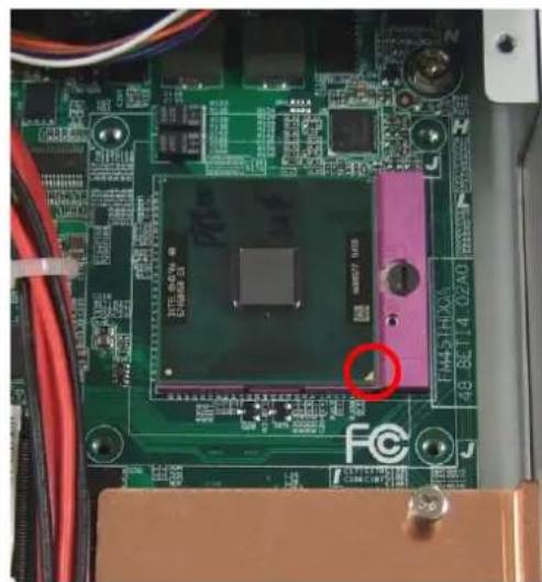
natural_image
Close-up of a green printed circuit board with a central processor and red circular annotation (no readable text or symbols)2-5-4.
Lock the CPU socket screw clockwise

natural_image
Interior view of an electronic circuit board with visible components and wiring (no readable text or symbols)2-5-5.
Place the CPU cooler back and follow up the sequence to screw it tightly
(Screwdriver torque : 3.0 ±0.5 kgf. cm )

natural_image
Interior view of an electronic device showing internal components and wiring (no readable text or symbols)2-5-6.
Place the Top Cover back and screw it tightly with 4 pcs of FPH M3 screws by the screw driver. (Screwdriver torque : 3.0 ±0.5 kgf. cm )
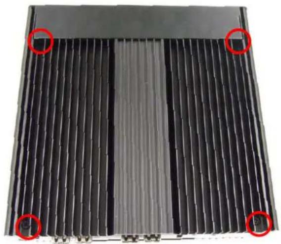
natural_image
Close-up of a black corrugated metal panel with four red-circled highlights (no text or symbols visible)2-6 Install HDD
2-6-1
Turn over the system and loosen 4 pcs of Bottom cover screw ( FPH M3 screw ) by the screw driver and remove it

natural_image
Black metal panel with white mounting flanges and red circular annotations highlighting features (no text or symbols)2-6-2
Remove the Bottom Cover.
HDD Bracket

natural_image
Interior view of a computer monitor case with visible wiring and a red arrow indicating direction (no text or symbols)Power & SATA cable
2-6-3.
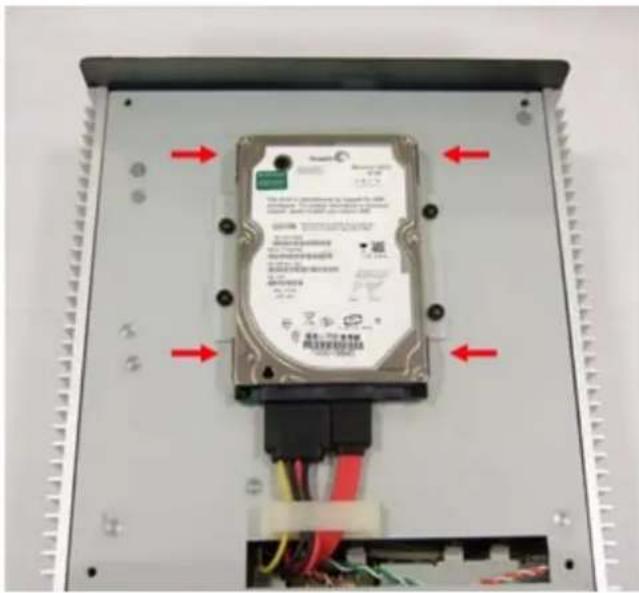
Connect HDD to SATA and Power cable, then put HDD on the HDD bracket.
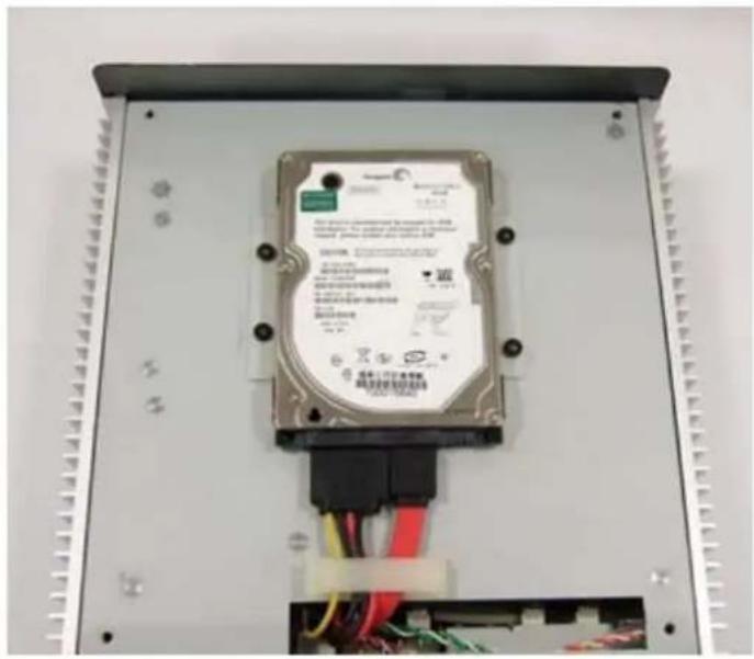
2-6-4.
Tighten HDD with 4pcs of FPH M3 screw (on both flanks)
(Screwdriver torque : 2.5 ±0.1 kgf. cm )
natural_image
Internal view of a hard disk drive housing with visible wiring and mounting points (no text or symbols on the device body)2-6-5.
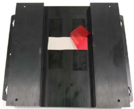
T
Bottom Cover before place it back.
natural_image
Black metal frame with a white rectangular object and a red 3D cube placed on top (no text or symbols visible)2-6-6.
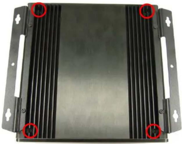
Place Bottle of other product My screw with highly pad on with 4 pcs of FPH M3 screws by the screw driver.
(Screwdriver torque : 3.0 ±0.5 kgf. cm )
natural_image
Black metal panel with white connectors and red circular annotations (no readable text or symbols)2-7.
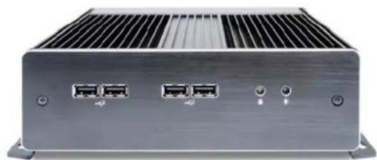
Place Front Panel back and screw it tightly with 2 pcs of FPH M3 screws by the screw driver. (Screwdriver torque : 3.0 ±0.5 kgf. cm )

natural_image
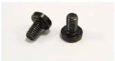
Front view of a black electronic device with four ports and two red circular buttons (no visible text or symbols)FPH M3xL5 Screw

natural_image
Two black threaded fasteners on a plain white background (no text or symbols visible)NDE
natural_image
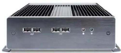
Front view of a silver industrial electronic device with multiple ports and ventilation grilles (no visible text or labels)3. Install Key components (Including Mini card module installation)
3-1.
Loosen 2 pcs of front panel screw (FPH M3 screw) by the screw driver and remove it.

natural_image
Back panel of a black electronic device with three ports and two red circular annotations pointing to the left port (no text or symbols on the device itself)Unscrew 2 x FPH M3 screw
3-2.
Loosen 4 pcs of Top cover screw (FPH M3 screw) by the screw driver and remove it.

natural_image
Close-up of a black panel with red annotation arrows pointing to specific edges (no text or symbols present)Unscrew 4 x M3 screw
3-3.
You will see the kernel of Digital Engine.

3-4 Install WLAN & TV-Tuner Module.
3-4-1. 3-4-2.
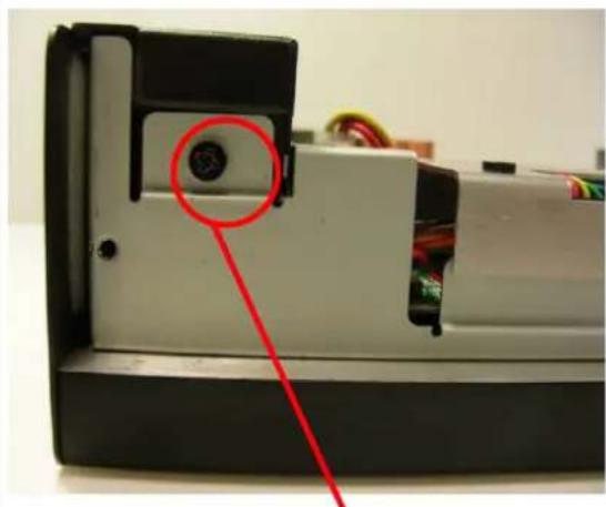
Loosen 2 pcs of DIMM heat sink – AL cover screw (FPH M3 screw) by the screw driver and remove it.

Loosen 1 pcs of Top-Back cover screw (FPH M3 screw) by the screw driver and remove it.
natural_image
Close-up of a mechanical device component with a red circle highlighting a specific pin (no visible text or symbols)Unscrew
3-4-3. 3-4-4.
Loosen 2 pcs of MCH heat sink – AL cover screw (FPH M3 screw) by the screw driver and remove it.

Loosen 1 pcs of Top-Back Cover screw (FPH M3 screw) by the screw driver and remove it.

3-4-5. 3-4-6.
Remove Top -Back Cover.

natural_image
Close-up of a gloved hand installing or adjusting electronic components on an open circuit board, with a red upward arrow indicating motion (no text or symbols visible)Loosen 4 pcs of DIMM & ICH heat sink screw (FPH M3 screw) by the screw driver and remove it.

3-4-7. 3-4-8.
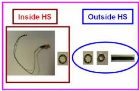
WLAN Mini card module List.

Loosen 1 pcs of Mini Card screw by the screw driver and remove it.

3-4-9. 3-4-10.
Install WLAN Mini card and fix 1 pcs of Mini Card screw by the screw driver.
(Screwdriver torque : 1.0 ±0.1 kgf. cm )

Remove the metal cover of the WLAN antenna hole by the screw driver.

3-4-11.
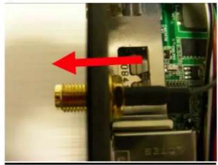
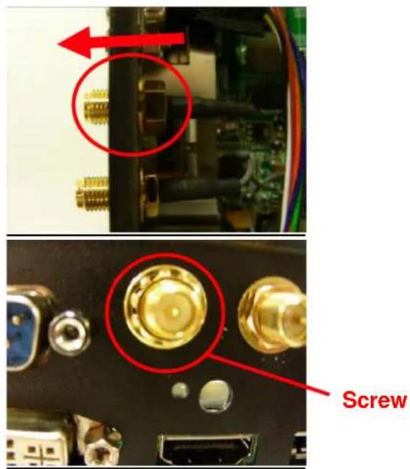
Insert WLAN Antenna into the hole. Tighten the nut by the screw sleeve. (The diameter of the nut is 8mm).
natural_image
Close-up of a computer motherboard with a red arrow pointing to a component (no visible text or symbols)
natural_image
Close-up of a computer interface showing a gold connector and multiple Ethernet ports (no text or symbols visible)Screw
3-4-12.
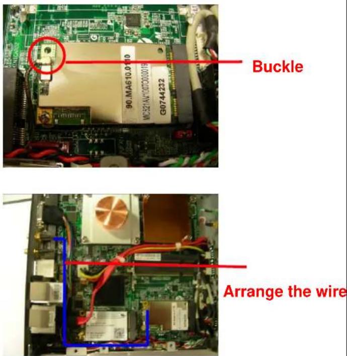
Buckle the mini card with the Antenna wire (CON1) and arrange the wire according to the photo.

Buckle

natural_image
Internal view of a computer motherboard with visible circuitry and wiring (no readable text or symbols)Arrange the wire
3-4-13. 3-4-14.
TV-Tuner Mini card module List.

natural_image
Three electronic components laid out on a plain surface: a small circuit board, a black cable with wires, and a black antenna (no visible text or symbols)
Loosen 1 pcs of Mini Card screw by the screw driver and remove it.

3-4-15. 3-4-16.
Install TV-Tuner Mini card and fix 1 pcs of Mini Card screw by the screw driver. (Screwdriver torque: 1.0 ± 0.1 kgf. cm)

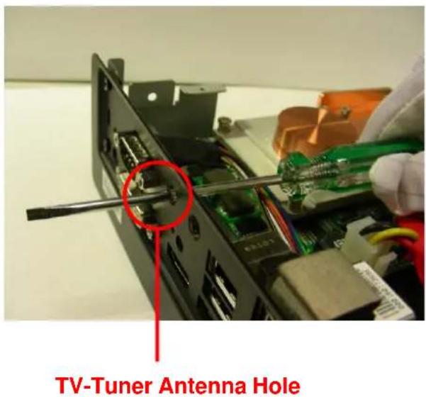
Remove the metal cover of the TV-Tuner antenna hole by the screw driver.
3-4-17. 3-4-18.
Insert TV-Tuner Antenna into the hole. Tighten the nut by the screw sleeve. (The diameter of the nut is 8mm).
Buckle the mini card with the Antenna wire and arrange the wire according the photo.
3-4-19. 3-4-20.
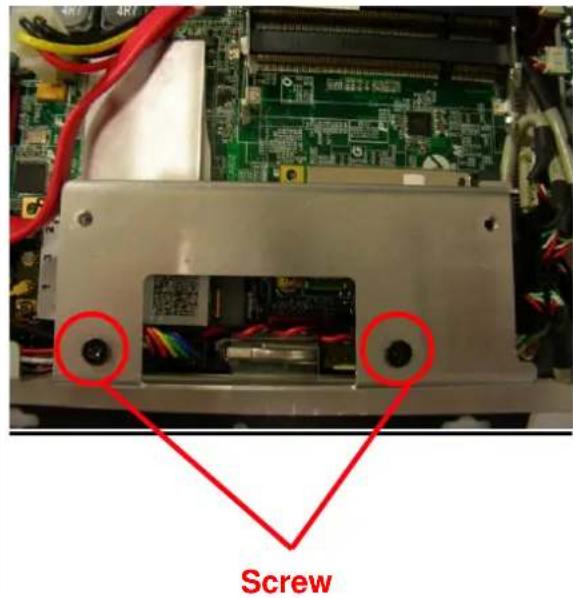
Install ICH heat sink vertically and tighten 2 pcs of screw (FPH M3 screw) by the screw driver.
(Screwdriver torque : 3.0 ±0.5 kgf. cm )
Install Top -Back Cover.

natural_image
Close-up of a gloved hand installing or adjusting a black electronic device with visible wiring and components (no text or symbols)3-4-21. 3-4-22.
Tighten 2 pcs of Top -Back Cover screw (FPH M3 screw) by the screw driver. (Screwdriver torque : 3.0 ±0.5 kgf. cm )

Tighten 4 pcs of DIMM & MCH heat sink – AL covers screw (FPH M3 screw) by the screw driver.
(Screwdriver torque : 3.0 ±0.5 kgf. cm )

3-4-23. 3-4-24.
Note that DIMM & MCH heat sink – AL cover have to be installed in the correct position to avoid influence the thermal efficiency.

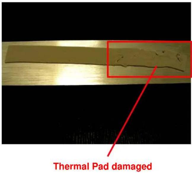
Note that detach ICH heat sink after DIMM heat sink – AL cover has already to be detached to avoid damage the thermal pad.
3-5-1. 3-5-2.
Insert the memory on the upper socket as this angle.


Press the DIMM as flat on the Motherboard, and you will hear the click voice.

natural_image
Close-up of an electronic circuit board with copper and infrared components, showing a green circuit board and red annotations (no readable text or symbols)Make sure it clicks
3-5-3.
Take off the protect Mylar of thermal pad of DIMM heatsink and place it back to ICH heatsink.

natural_image
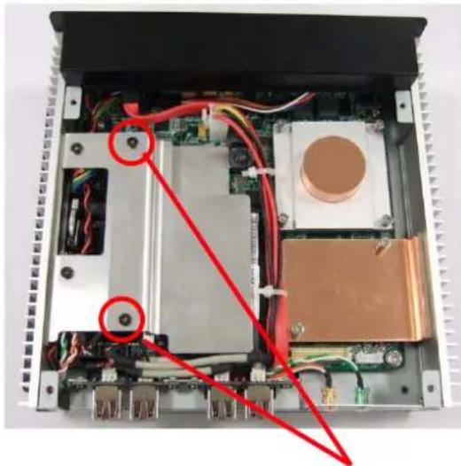
Metallic metal bracket with a red and pink patch, no text or symbols visible3-5-4.
Screw it tightly with 2 pcs of FPH M3 screws by the screw driver
(Screwdriver torque : 3.0 ±0.5 kgf. cm )
natural_image
Interior view of an electronic device showing internal components like CPU, memory, and circuit board (no text or symbols visible)Screw
3-6 Install CPU
3-6-1.
Loosen 4 pcs of CPU cooler screw by the screw driver and remove it.

3-6-2.
Unlock the CPU socket screw. Counterclockwise.

natural_image
Close-up of a green circuit board with a pink CPU socket and soldering tool inserted, no visible text or symbols3-6-3
Put the CPU into the socket, and check the direction.

natural_image
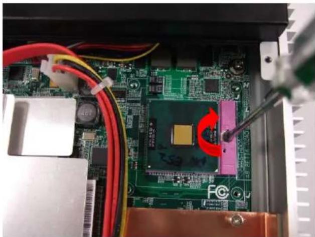
Close-up of a green printed circuit board with a central processor and red circular annotation (no readable text or symbols)3-6-4.
Lock the CPU socket screw clockwise
natural_image
Close-up of an electronic circuit board with visible components and wiring, no readable text or symbols present.3-6-5.
Place the CPU cooler back and follow up the sequence to screw it tightly
(Screwdriver torque : 3.0 ±0.5 kgf. cm )

3-6-6.
Place the Top Cover back and screw it tightly with 4 pcs of FPH M3 screws by the screw driver.
(Screwdriver torque : 3.0 ±0.5 kgf. cm )

natural_image
Close-up of a black corrugated metal panel with four red-circled highlights (no text or symbols visible)3-7 Install HDD
3-7-1
Turn over the system and loosen 4 pcs of Bottom cover screw (FPH M3 screw) by the screw driver and remove it.

natural_image
Black plastic heat exchanger or cooling unit with red circular annotations highlighting specific components (no text or symbols visible)3-7-2
Remove Bottom Cover.
HDD Bracket

natural_image
Interior view of an electronic device showing a circuit board with connectors and wiring, marked by red arrows (no text or symbols visible)Power & SATA cable
3-7-3.
Connect HDD to SATA and Power cable, then put HDD to HDD bracket

natural_image
Internal view of a hard disk drive with visible wiring and connectors (no readable text or symbols)3-7-4.
Tighten HDD with 4pcs of FPH M3 screw (on both flanks)
(Screwdriver torque : 2.5 ±0.1 kgf. cm )

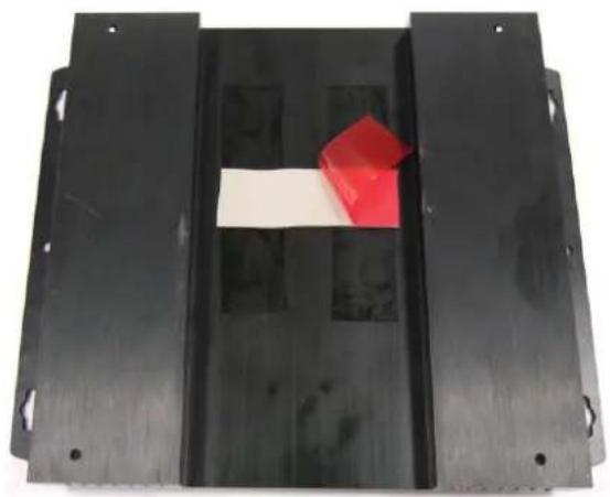
3-7-5.
T
Botwidth4Close of FeRheMoBaseribly.the scre
natural_image
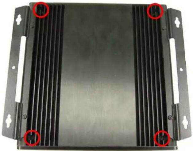
Black metal frame with a white rectangular object and a red 3D cube placed on top (no text or symbols visible)3-7-6.
Place BothbendoftherprotecaMlyserovtheighallypad on w
driver.
(Screwdriver torque : 3.0 ±0.5 kgf. cm )
natural_image
Black plastic heat sink component with red circular annotations highlighting specific areas (no text or symbols present)3-8.
Place Front Panel back and screw it tightly with 2 pcs of FPH M3 screws by the screw driver. (Sewdriver torque: 3.0 ± 0.5 kgf. cm)

natural_image
Front view of a black electronic device with four ports and two red circular markers on the left side (no visible text or symbols)FPH M3xL5 Screw
natural_image
Two black plastic screw nuts on a plain white background (no text or symbols visible)NDE
natural_image
Front view of a silver industrial electronic device with three ports and ventilation grille (no visible text or symbols)4. Connector & PINs definitions
4-1.
COM1 connector

4-2
Front Panel connector

4-3. 4-4.
USB 2.0 connector Front Audio connector


Appendix 1 Packing List
1 x DEX4500 system
1 x Easy Assembly Guide
1 x Driver CD
1 x 90W Adapter and Power Cord
4 x M3 - L5 screws
2 x Cable clamp
1 x DVI to VGA adapter
☐ 1 x SATA to Compact Flash card bridge
☐ 1 x HDMI to DVI cable
☐ 12 x HEX screw and 1 x HEX key
Appendix 2 Table of Screw and Torque
| No. | Screw Photo Position | Q'ty Screw spec. | Torque Screw driver | spec. |
| 1 | 12 FPH M3- L5 | 3.0 ± 0.5 | kgf-cm | |
Appendix 3 Watch Dog Timer Configuration
The WDT is used to generate a variety of output signals after a user programmable count. The WDT is suitable for use in the prevention of system lock-up, such as when software becomes trapped in a deadlock. Under these sort of circumstances, the timer will count to zero and the selected outputs will be driven. Under normal circumstance, the user will restart the WDT at regular intervals before the timer counts to zero.
CODE FLOW-CHART
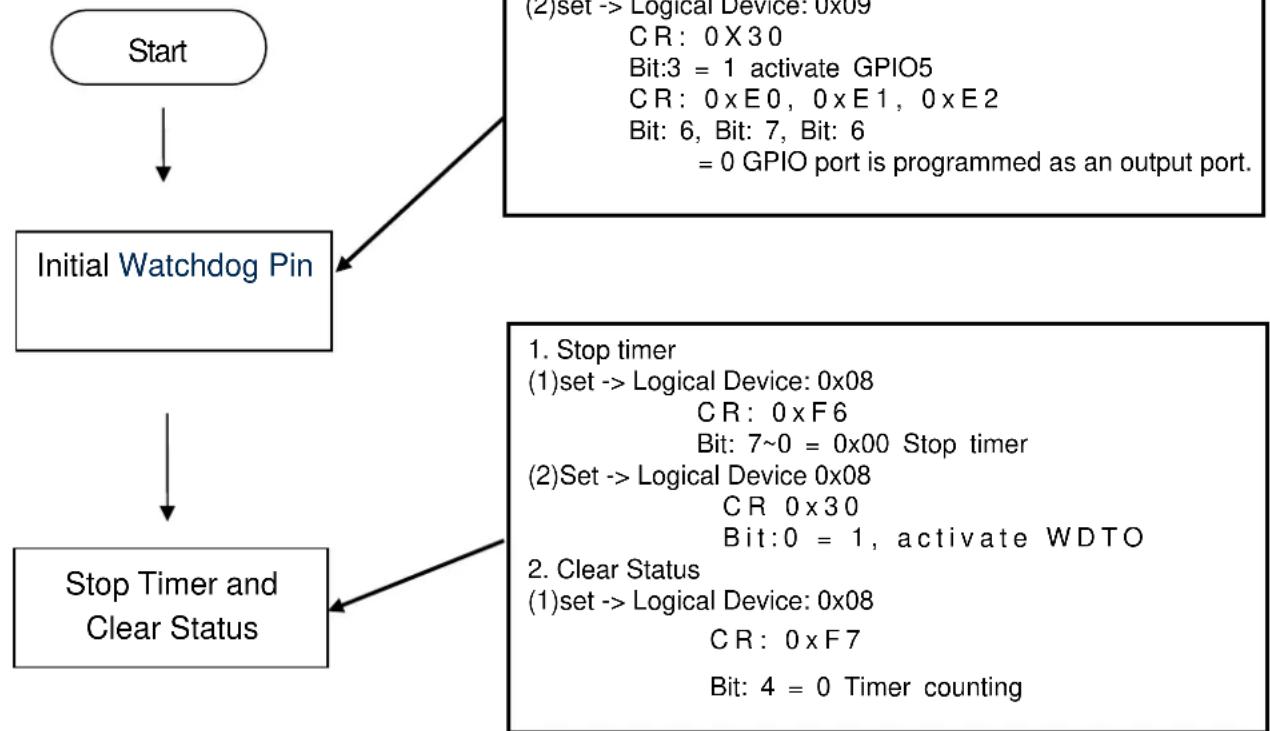
flowchart
graph TD
    A["Start"] --> B["Initial Watchdog Pin"]
    B --> C["Stop Timer and Clear Status"]
    C --> D["(1) set --> Logical Device: 0x08\nCR: 0 x F7\nBit: 4 = 0 Timer counting\n(2) Set --> Logical Device: 0x08\nCR: 0 x F6\nBit: 7~0 = 0x00 Stop timer\n(2) Set --> Logical Device: 0x08\nCR: 0 x F3\nBit: 0 = 1, activate WDTO\n(2) Set --> Logical Device: 0x09\nCR: 0 x F30\nBit: 3 = 1 activate GPIO5\nCR: 0 x E0, 0 x E1, 0 x E2\nBit: 6, Bit: 7, Bit: 6\n= 0 GPIO port is programmed as an output port."]

flowchart
graph TD
    A["Set Min/Sec Mode"] --> B["Start Timer"]
    B --> C["End"]
    D["1. Set Mode\n(1)set --> Logical Device: 0x08\nCR: 0xF5\nBit: 3\n= 0 By second\n= 1 By minute"] --> A
    B --> E["1. Set Mode\n(1)set --> Logical Device: 0x08\nCR: 0xF6\nBit: 7~0\n= 0x01 Time- out occur after 1\ndecond/minute\n...\n= 0xFF Time- out occur after 255 second/minute"]
SAMPLE CODE:
This code and information is provided "as is" without warranty of any kind, either expressed or implied, including but not limited to the implied warranties of merchantability and/or fitness for a particular purpose. This program just for MB with Winbond W83267DHG LPC I/O
- InitWatchdogPin:
| outportb(0x2E,0x87); | outportb(0x2E,0x87); | outportb(0x2E,0x87); |
| outportb(0x2E,0x87); | outportb(0x2E,0x87); | outportb(0x2E,0x87); |
| outportb(0x2E,0x07); | outportb(0x2E,0x07); | outportb(0x2E,0x07); |
| outportb(0x2F,0x01); | outportb(0x2F,0x09); | outportb(0x2F,0x09); |
| outportb(0x2E,0x2D); | outportb(0x2E,0xE0); | outportb(0x2E,0xE2); |
| outportb(0x2F,byBit); | outportb(0x2F,byBit); | outportb(0x2F,byBit); |
| outportb(0x2E,0xAA); | outportb(0x2E,0xAA); | outportb(0x2E,0xAA); |
| outportb(0x2E,0x87); | outportb(0x2E,0x87); |
| outportb(0x2E,0x87); | outportb(0x2E,0x87); |
| outportb(0x2E,0x07); | outportb(0x2E,0x07); |
| outportb(0x2F,0x09); | outportb(0x2F,0x09); |
| outportb(0x2E,0x30); | outportb(0x2E,0xE1); |
| outportb(0x2F,byBit); | outportb(0x2F,byBit); |
| outportb(0x2E,0xAA); | outportb(0x2E,0xAA); |
- Stop Timer
| outportb(0x2E,0x87); |
| outportb(0x2E,0x87); |
| outportb(0x2E,0x07); |
| outportb(0x2F,0x08); |
| outportb(0x2E,0xF6); |
| outportb(0x2F,byBit); |
| outportb(0x2E,0xAA); |
| outportb(0x2E,0x87); |
| outportb(0x2E,0x87); |
| outportb(0x2E,0x07); |
| outportb(0x2F,0x08); |
| outportb(0x2E,0xF7); |
| outportb(0x2F,byBit); |
| outportb(0x2E,0xAA); |
| outportb(0x2E,0x87); |
| outportb(0x2E,0x87); |
| outportb(0x2E,0x07); |
| outportb(0x2F,0x08); |
| outportb(0x2E,0x30); |
| outportb(0x2F,byBit); |
| outportb(0x2E,0xAA); |
| 3. Set Min/Sec Mode |
| outportb(0x2E,0x87); |
| outportb(0x2E,0x87); |
| outportb(0x2E,0x07); |
| outportb(0x2F,0x08); |
| outportb(0x2E,0xF5); |
| outportb(0x2F,byBit); |
| outportb(0x2E,0xAA); |
| 4. Start Timer |
| outportb(0x2E,0x87); |
| outportb(0x2E,0x87); |
| outportb(0x2E,0x07); |
| outportb(0x2F,0x08); |
| outportb(0x2E,0xF6); |
| outportb(0x2F,byBit); |
| outportb(0x2E,0xAA); |
Appendix 4 Outline Drawing

P/N : 49.DE201.0010
S/N : 088-099-118

- Assembly Guide for DEX4500 series
- Index
- Outlook
- Install Key components (Except Mini card module installation)
- 2-1.
- 2-2.
- 2-3.
- 2-4 Install Memory
- 2-4-1.
- 2-4-2.
- 2-4-3. 2-4-4.
- 2-4-5.
- 2-5 Install CPU
- 2-5-1.
- 2-5-2.
- 2-5-3
- 2-5-4.
- 2-5-5.
- 2-5-6.
- 2-6 Install HDD
- 2-6-1
- 2-6-2
- 2-6-3.
- 2-6-4.
- 2-6-5.
- 2-6-6.
- 2-7.
- NDE
- Install Key components (Including Mini card module installation)
- 3-1.
- 3-2.
- 3-3.
- 3-4 Install WLAN & TV-Tuner Module.
- 3-4-1. 3-4-2.
- 3-4-3. 3-4-4.
- 3-4-5. 3-4-6.
- 3-4-7. 3-4-8.
- 3-4-9. 3-4-10.
- 3-4-11.
- 3-4-12.
- 3-4-13. 3-4-14.
- 3-4-15. 3-4-16.
- 3-4-17. 3-4-18.
- 3-4-19. 3-4-20.
- 3-4-21. 3-4-22.
- 3-4-23. 3-4-24.
- 3-5-1. 3-5-2.
- 3-5-3.
- 3-5-4.
- 3-6 Install CPU
- 3-6-1.
- 3-6-2.
- 3-6-3
- 3-6-4.
- 3-6-5.
- 3-6-6.
- 3-7 Install HDD
- 3-7-1
- 3-7-2
- 3-7-3.
- 3-7-4.
- 3-7-5.
- 3-7-6.
- 3-8.
- Connector & PINs definitions
- 4-3. 4-4.
- Appendix 1 Packing List
- Appendix 2 Table of Screw and Torque
- Appendix 3 Watch Dog Timer Configuration
- SAMPLE CODE:
- Appendix 4 Outline Drawing
Brand : AOPEN
Model : DEX4502
Category : Industrial computer