
i4800 - Uncategorized PHONIC - Free user manual and instructions
Find the device manual for free i4800 PHONIC in PDF.


| Product Type | Audio Mixer/Amplifier |
| Dimensions (W x H x D) | 480 mm x 100 mm x 300 mm |
| Weight | 5 kg |
| Power Supply | 100-240 V AC, 50/60 Hz |
| Power Consumption | 150 W |
| Number of Input Channels | 8 |
| Output Power | 2 x 200 W RMS |
| Frequency Response | 20 Hz - 20 kHz |
| Input Impedance | 10 kΩ (balanced) |
| Output Impedance | 4-8 Ω |
| Signal-to-Noise Ratio | >90 dB |
| Total Harmonic Distortion | <0.05% |
| Cooling System | Fan assisted |
| Primary Functions | Mixing, amplification, EQ, effects send/return |
| Maintenance & Cleaning | Wipe with dry cloth; avoid liquids |
| Safety | Operate in well-ventilated area; unplug when not in use |
| Spare Parts & Repairability | Contact Phonic support for genuine parts |
| General Information | User manual included; designed for professional audio |
Frequently Asked Questions - i4800 PHONIC
User questions about i4800 PHONIC
0 question about this device. Answer the ones you know or ask your own.
Ask a new question about this device
Download the instructions for your Uncategorized in PDF format for free! Find your manual i4800 - PHONIC and take your electronic device back in hand. On this page are published all the documents necessary for the use of your device. i4800 by PHONIC.
USER MANUAL i4800 PHONIC
Professional Audio Processor
i4800/i3600 User Manual
Index
Chapter 1: Introduction ...... 3
Chapter 2: Technical Parameters .... 3
2.1 Features....3
Chapter 3 Functional Structure .... 5
3.1 LCD display function menu 6
3.2 Control buttons....6
3.3 Input section....6
3.4 Output section 7
Chapter 4: Introduction to PC Software ....7
Chapter 5: Software Installation ....7
5.1 Operating environment 7
5.2 Software installation....7
5.3 Software operating 8
Chapter 6 Software Interface Description....9
6.1 Introduction to Interface Module....9
Chapter 7 Function Interface Introduction ...... 16
7.1 Main interface of input function 16
7.2 Test signal function....16
7.3 Input noise gate 17
7.4 Input Parametric Equalizer (PEQ) 18
7.5 Dynamic EQ 20
7.6 Input delay....21
7.7 Input and output with FIR....22
7.8 Matrix mixing....23
7.9 Output Parametric Equalizer (PEQ) 23
7.10 Output delay....24
7.11 Output compressor....25
7.12 Output limiter 25
7.13 Output module 26
7.14 Input and output channel volume monitoring 27
7.15 Channels link....27
7.16 Device list....28
7.17 Add device 28
7.18 Device Management....29
7.19 Channel name management 29
7.20 Channels copy....30
7.21 Device Preset....31
7.22 Firmware upgrade 31
Chapter 8 Introduction to Dante....33
Chapter 1: Introduction
This series including i4800 and i3600 are professional speaker processors that can realize a variety of DSP functions. This series of products are integrated with compressors, limiters, frequency dividers, dynamic EQ, delayers, equalizers, input and output with FIR phase correction, and audio mixers. The matrix can be quickly debugged and monitored through the beautiful and intuitive software, which provides a broad operating space for the construction and operation of professional audio amplification systems. D4 represents the function of configuring 4 channels of Dante network audio input and output interfaces.
Applications
▲ Are na
▲ Stadium
▲Professional performance
▲ Auditorium
▲ Multi- functional hall
▲Conference system
Chapter 2: Technical Parameters
2.1 Features
▲ i3600 provides with 3 input channels and 6 output channels, i4800 provides with 4 input channels and 8 output channels
▲ Uncompromising top audio performance
▲ Unique and precise 96kHz/24bit digital signal processing
▲ Analog and Dante™ (optional) inputs and outputs
▲ Ethernet remote control through PHONIC's PiWare drive free application
▲ Complete front panel user interface provides simple and intuitive local operation
▲ TCP/IP LAN remote control, support RS232 central control, easy system integration
▲ Designed, manufactured, tested and supported by PHONIC CORPORATION
2.2 Technical Parameters
| DSP MODULE | |
| Signal processing | ADI SHARC 21489 |
| Audio system delay | 1.8 ms |
| D/A conversion | 24- bit |
| Sampling Rate | 96kHz |
| ANALOG AUDIO INPUTS AND OUTPUTS | |
| Input channel | 4 balanced inputs. Line level |
| Audio interface | Cannon male and female |
| Input resistance | 11kΩ |
| Maximum input level | 16dBu/Line |
| Output channel | 8 balanced outputs, Line level |
| Output impedance | 100Ω |
| AUDIO PERFORMANCE SPECIFICATIONS | |
| Frequency response curve | 20Hz□ 40kHz(±0.5dB)/Line |
| Noise floor | 20Hz□ 20kHz, A- wt, -93dBu |
| THD+ N | -90dB(@0dBu, 1kHz,A- wt)/Line |
| SNR | 108dB(@16dBu, 1kHz,A- wt)/Line |
| COMMUNICATION PORTS AND INDICATORS | |
| USB | Micro- B type, free drive |
| RS232 | Serial port communication |
| TCP/IP network port | RJ-45 |
| Indicator light | C LIP, LEVEL, EDIT, MUTE |
| ELECTRICAL AND PHYSICAL | |
| Power supply range | AC 90V□ 264V 50/60 Hz |
| power dissipation | Stand- by 11.6W, full load 11.8W |
| Operating temperature | -20°C□ 80°C |
| Product dimension | 483mm×215mm×44.5mm |
| Net weight | 3.2kg |
Chapter 3 Functional Structure
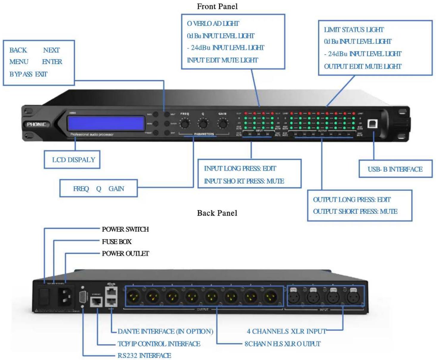
3.1 LCD display function menu

- Device name: The user can customize and modify the name through the control software or the lower computer.
- Device IP: When the device is connected to the software via TCP/IP, the device and the computer must be in the same IP domain, for example, the device IP is 169.254.xxx.xxx, and the computer IP should be 169.254.xxx.xxx.
- Current gear: the preset currently applied by the device, Default is the default gear of the device.
- Security lock: When this icon appears, the keys and knobs of the device are inoperable, press and hold [ENTER] for 5 seconds to unlock (can cancel the lock screen on the menu page).
- Device firmware version: display the firmware version burned by the device.
3.2 Control buttons
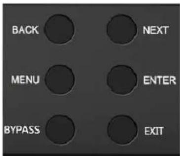
BACK(Up key): Function and parameter selection.
NEXT (Down key): Function and parameter selection.
MENU (Menu key): Enter the main menu, use [BACK] and [NEXT] keys to select different sub-menus.
ENTER (Enter key): Enter submenu or function to edit parameters; confirm selection; change parameters.
BYPASS (Bypass key): Make the currently selected function inoperative.
EXIT (Exit key): Exit the current editing state or the current menu
3.3 Input section
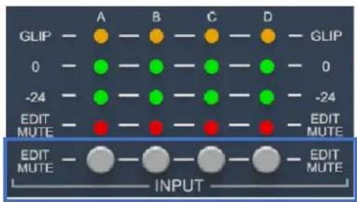
EDIT/MUTE button (mute and edit button):
Long press [EDIT/MUTE key] EDIT/MUTE light turns on blue light, enters the channel menu editing mode, lights up multiple channels at the same time, enters the channel joint edit mode, click other input channels at this time, there will be more than two channels lighted blue at the same time Light, indicating joint adjustment of channel functions;
Short press [EDIT/MUTE key] The EDIT/MUTE indicator lights up in red, and the channel is muted; the EDIT/MUTE indicator lights up in purple when the edit mode and mute are turned on at the same time;
Use [BACK] and [NEXT] Keys to switch functions and parameter editing.
3.4 Output section
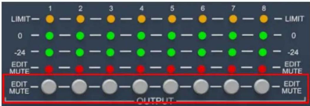
EDIT/MUTE button (mute and edit button): Refer to the input section for function editing and operation mode.
Chapter 4: Introduction to PC Software
Software provides users quickly interact with all the parameters of one or more machines. It can store the configuration parameters of the machine in the machine and the computer, providing a very convenient way to preset scenes and parameters for different systems. The software has high execution efficiency and clear interface structure.
Chapter 5: Software Installation
5.1 Operating environment
The software is suitable for WIN7/WIN8/WIN10 x86/x64 operating system with Microsoft .NET Framework 4.0 runtime.
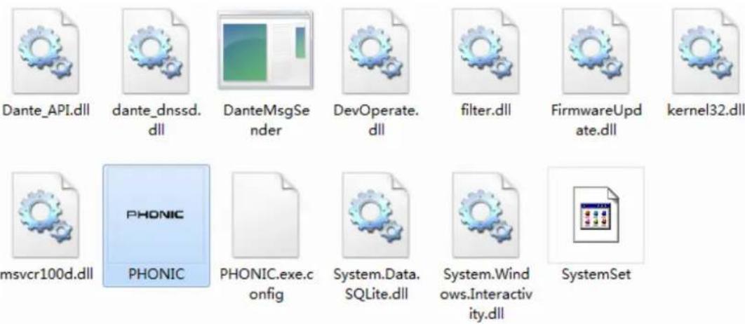
Figure 5.1
5.2 Software installation
This software is a green version and does not require installation. The folder contains the following files or folders, all of which are indispensable. The green version of the software does not include the Microsoft .NET Framework 4.0 runtime. If necessary, please download and install it from the official Microsoft website.
5.3 Software operating

Steps: Double-click the executable file in the folder PHONIC.exe , enter the main interface of the software, as shown in
Figure 5.1.
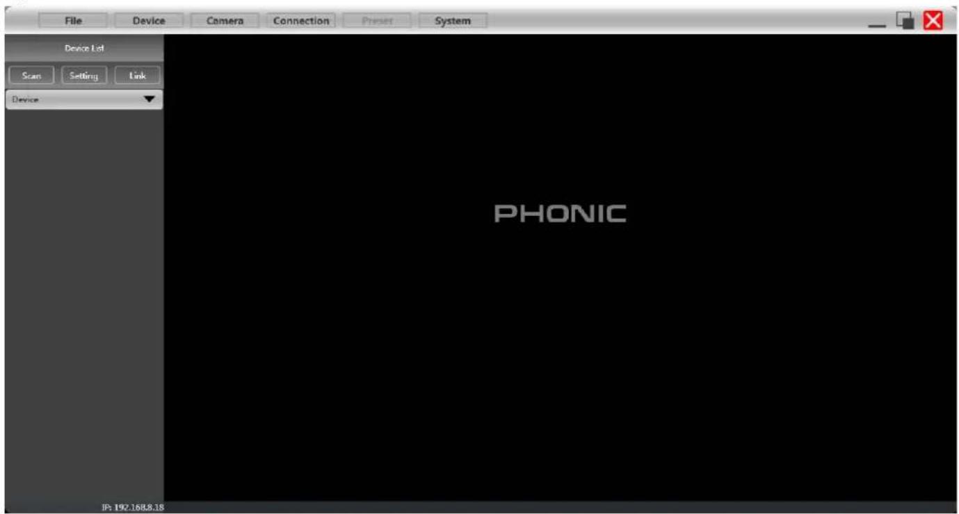
Figure 5.1 The main interface of the software
Note: Please keep only one software open for each computer!
Chapter 6 Software Interface Description
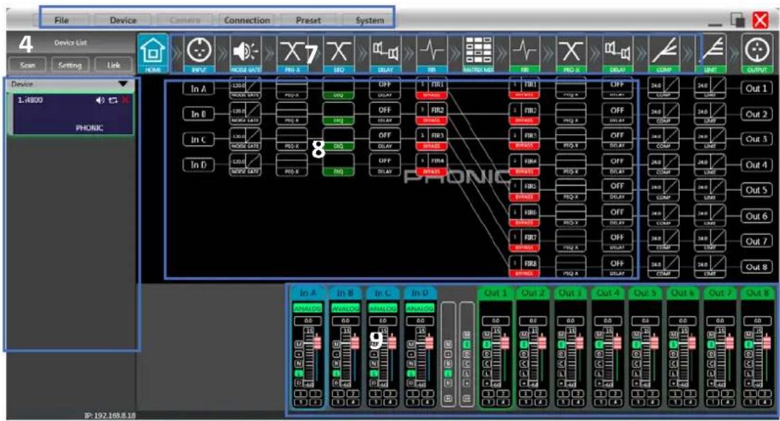
Figure 6.1 main function interface
6.1 Introduction to Interface Module
As shown in Figure 6.1, the module corresponding to the red word in the main interface of the function, each module is as follows:
(1) Menu bar
(2) Scan button
(3) Setting button
(4) Joint debugging button
(5) Equipment list
(6) Computer IP address
(7) Function control keys
(8) Function status interface
(9) Volume monitoring of input and output channels
6.1.1 Menu bar
File
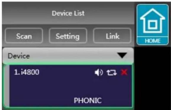
Figure 6.1.1 "File" menu
As shown in Figure 6.1.1 "File" menu:
- New, new project, the project is restored to the initial open state.
- Add new devices, add virtual devices, you can view all the functions of the device without affecting the specific device connected.
- Open, open an existing device management project from the computer disk.
- Save, save the current equipment management project in the computer disk.
- Save as, save the current equipment management project to the computer disk.
Device
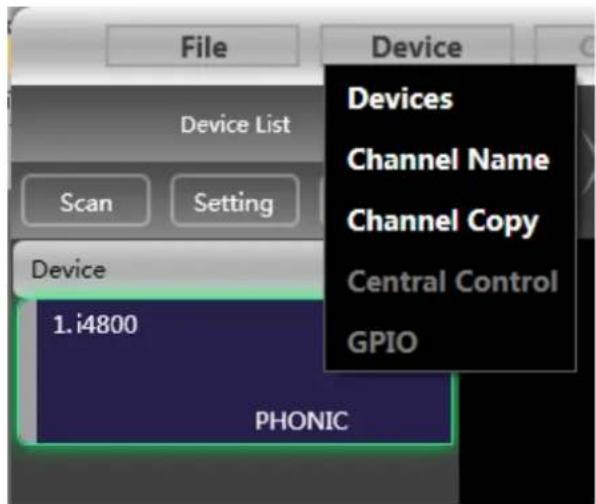
Figure 6.1.2 "Device" menu
As shown in Figure 6.1.2 "Device" menu:
Devices: view or modify the software version information, device name and device IP address of the upper and lower computer of the device.
Channel name: set the name of each input and output channel, with memory function.
Channel copy: copy device input and output channel parameters, can realize cross-device copy parameters (Note:
The same type of equipment is required).
Central control.
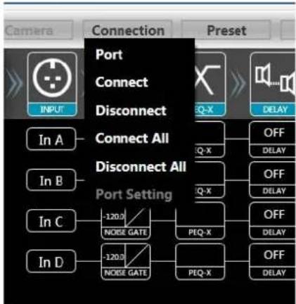
Connection
flowchart
graph TD
    A["Camera"] --> B["INPUT"]
    B --> C["Port"]
    B --> D["Connect"]
    B --> E["Disconnect"]
    C --> F["In A"]
    D --> G["In B"]
    E --> H["In C"]
    F --> I["120.0"]
    G --> J["120.0"]
    H --> K["120.0"]
    I --> L["NOISE GATE"]
    J --> M["NOISE GATE"]
    K --> N["PEQ-X"]
    L --> O["PEQ-X"]
    M --> P["PEQ-X"]
    N --> Q["OFF DELAY"]
    O --> R["OFF DELAY"]
Figure 6.1.3 "Connection" menu
As shown in Figure 6.1.3 "Connection" menu:
Port: set the connection mode, port number and baud rate, confirm the connection mode and then select the corresponding port.
Connect : connect and download the device parameters.
Disconnect: disconnect the connected device.
Connect all: connect and download the device parameters of all devices in the device list.
Disconnect all: disconnect all connected devices in the device list.
Preset
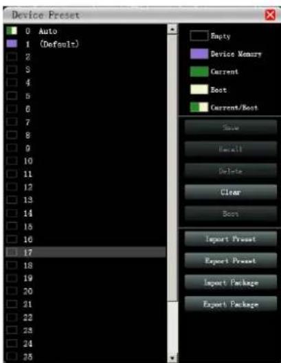
Figure 6.1.4 "Device Preset" menu
As shown in Figure 6.1.4 device preset menu:
Save: select the saved gear, save all the parameters of the current automatic gear of the machine to the device preset (2\~30 Preset bit).
Call: call the device preset to the current automatic gear position.
Delete: delete the existing preset, the default file cannot be deleted, over written or saved.
Clear: delete all presets in the device.
Set as the boot file: select a certain preset, after setting it as the boot file, each time the device is powered on, it will automatically call the save the parameters; the last set parameters need to be automatically saved, please set the
automatic file to the boot file.
Preset lock: lock the saved archive and set the password.
Preset unlock: Enter the password to unlock the saved archive.
Import preset: import a single preset file on the computer.
Export the preset: export all the parameters of the current state to the computer, and generate a single preset file.
Import preset package: import the preset package file containing multiple presets on the computer.
Export preset package: pack multiple presets in the machine's preset into one preset package and export it to the computer.
System
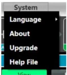
Figure 6.1.5 "System" menu
As shown in Figure 6.1.5 "System" menu:
Language: multi-language switching, supports simplified, traditional, and ENGLISH.
About: the current host computer software and device firmware version information.
Upgrade: call the upgrade applet to upgrade the firmware of the device.
6.1.2 Scan button
As shown in the following figure 6.1.6 progress display box, click the "Scan" button and directly scan all devices in the current connection mode and display the scanning progress
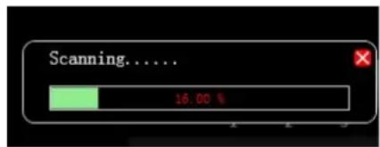
Figure 6.1.6 Progress display box
6.1.3 Set button
Select the corresponding device connection port and click the "Settings" button, and the port connection interface as shown in Figure 6.1.7 will pop up. Select the corresponding port and confirm after setting the parameters. If the device port changes, click the "Refresh" button in the lower left corner for instant Update port information.
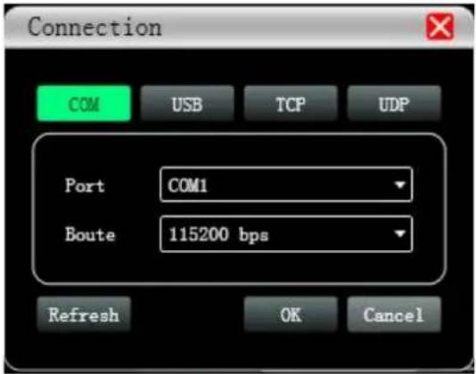
Figure 6.1.7 Port connection interface
6.1.4 Linkbutton
To set the parameters of multiple devices at the same time, click the "Link" button, and the following figure 6.1.8 Device networking link interface will pop up. Select the device of the same model in the left frame, move to the group in the middle frame, and then select the synchronization settings required After pressing the "OK" button, the grouping is successful. You can also use the same operation to modify the network grouping settings.
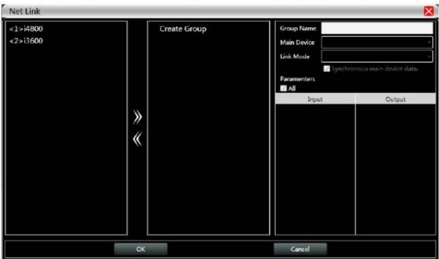
Figure 6.1.8 Device network link interface
6.1.5 Device list
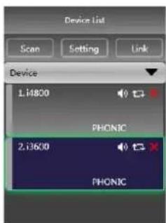
When a device is scanned or manually added, the corresponding device will be automatically added to the device list, and the user can operate on the target device, or operate multiple devices in groups at the same time.
6.1.6 Computer IP address
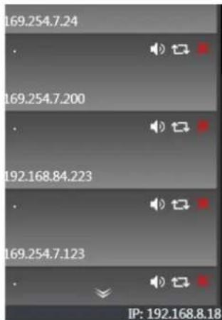
When the software is opened, it will automatically obtain the IP address of the computer system that the device is connected to. If there are 2 IP addresses, the first one is the IP address of the wireless network card by default, and the second is the IP address of the wired network card. If the device appears If the IP address and the computer IP addre are inconsistent, right-click the device to modify the device IP, or modify the computer IP address to ensure that the IP of the device and the computer are in the same network segment.
6.1.7 Function control keys

Open or close the related function interface and positioning module interface of the device. Double-click to open/close, and click to locate.
6.1.8 Function module interface
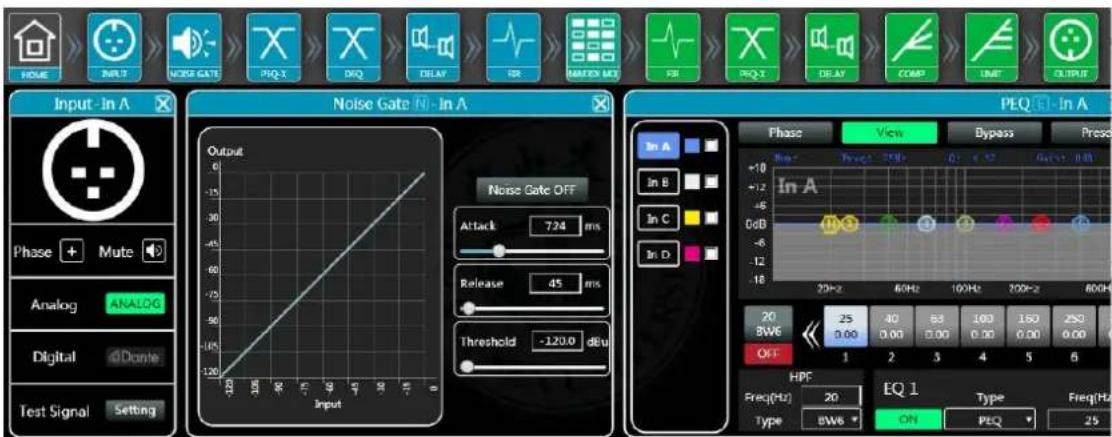
Each function module is opened and closed by the control key, and the function page and detailed parameters are displayed, and detailed settings can be made, and single or multiple functions can be operated freely. You can drag the function name position left and right to switch different function pages.
6.1.9 Input and output channel volume monitoring
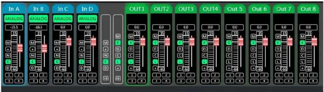
It can display the level, gain, input mode, channel name and other information of each channel, control the corresponding channel gain, DSP function master switch, and turn on the input and output channel grouping joint adjustment function to achieve more flexible and practical operability.
Chapter 7 Function Interface Introduction
7.1 Main interface of input function
Double-click in the function button, and the input function interface as shown in the Figure 7.1 below pops up.
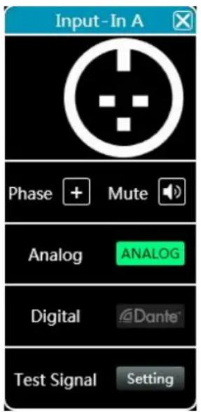
Figure 7.1 Channel input module
As shown in the Figure 7.1, the phase polarity, mute, and input modes of the corresponding input channels can be operated; in the input mode, analog input, digital input, and test signal can be selected from one of three, and a channel can only have one input mode.
In this software, only products with D4 display support Dante function, Dante digital input supports CHA-CHD four channels, and output supports Out1-Out4 channels; without Dante function, this button will become unavailable
7.2 Test signal function
In Figure 7.1 above, click the "Settings" button on the right side of "Test Signal" to pop up the test signal interface in Figure 7.2 below.
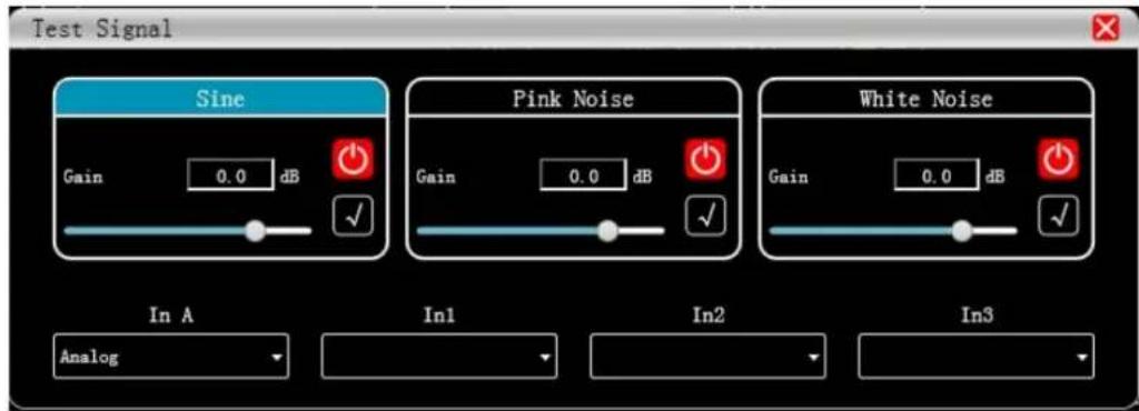
Figure 7.2 Test signal setting interface
As shown in the figure 7.2 above, it is divided into the upper half of the test signal switch setting options and the lower half of the channel selection test signal options.
Configure the three commonly used test signals (sine wave, pink noise, white noise) to set the switch and gain value, green is open, red is closed.
For channel selection, if you select "sine wave", "pink noise" and "white noise", the open test signal will enter the channel; if it is selected as an analog signal, it will switch back to analog signal input and turn off the test signal.
7.3 Input noise gate
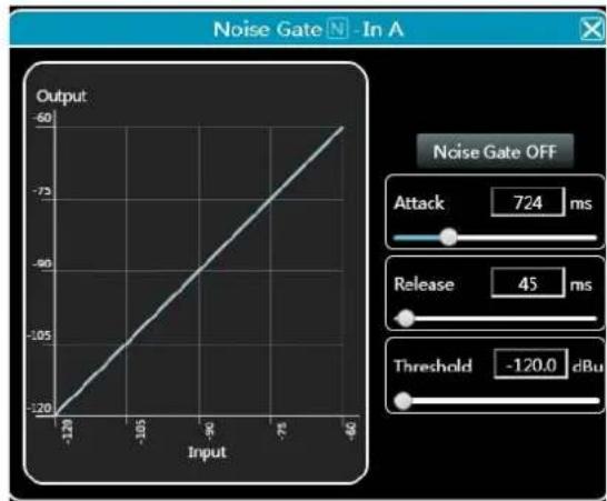
Double-click in the function button NOISE GATE, the following Figure 7.3 input noise gate function interface will pop up.
line
| Input | Output | |-------|--------| | -120 | -20 | | -105 | -105 | | -90 | -90 | | -75 | -75 | | -60 | -60 |Figure 7.3 Input noise gate setting module
As shown in the figure above, click the noise gate switch Noise Gate ON in the upper right corner on and the red is off. The attack time, release time, and threshold level are the parameters corresponding to the noise gate function. You may drag the slider or block values corresponding to the input numerical values 724
When the noise gate function is turned on, the points in the graph on the left

can be dragged diagonally to adjust
the value of the start control level.
7.4 Input Parametric Equalizer (PEQ)
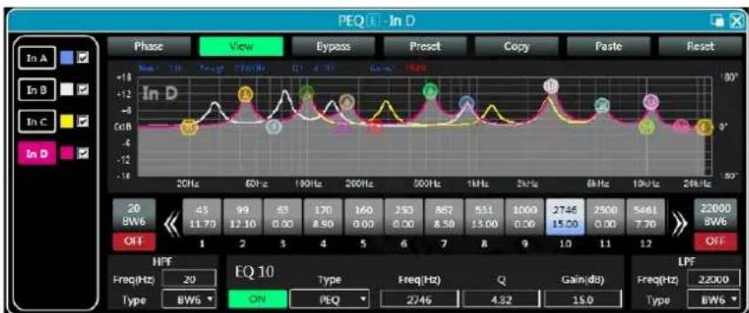
Double-click in the function button PEQ-X to pop up the parameter equalizer page as shown in the figure 7.4 below.
The button in the upper right corner of the module can enlarge this interface for easier debugging.
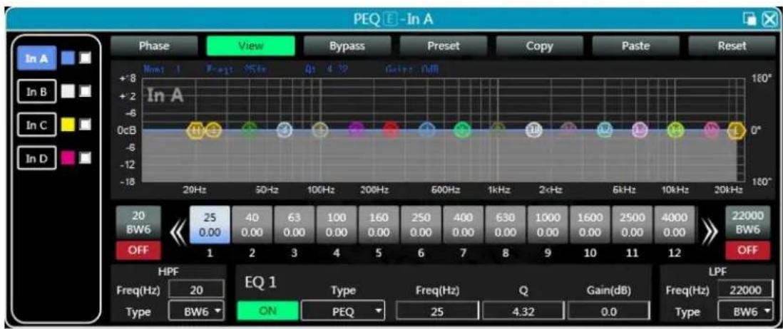
Figure 7.4 Input equalizer setting module
7.4.1 Function buttons
As shown in Figure 7.4 above, the functions of the top buttons are.
Phase curve: display the phase curve of the current channel.
View: show or hide all balance control points.
Bypass: turn on or off all equalizer EQ of the current channel at the same time
Preset: save all the setting parameters of the equalizer of the current channel to the computer, and recall the channel equalizer parameters of the computer, which can be called across channels and devices.
Copy: copy the current channel equalizer parameter value, which can be pasted to other similar channels (such as input channel parameters can only be copied to other input channels).
Paste: used in combination with the copy button to paste the last copied equalizer parameter value to the current channel.
Reset: reset the equalizer parameters to the default parameter values.
7.4.2 Multi-channel EQ curve display
Page 18 / 34
As shown in the figure above, the left side In A is the interface switching button for each channel. Click to switch the EQ channel, and the color is the currently selected channel. Is the curve color of the EQ channel. For each channel's EQ curve display switch, check it to enable it to display the curves of other channels in the current channel interface.
7.4.3 EQ curve chart
line
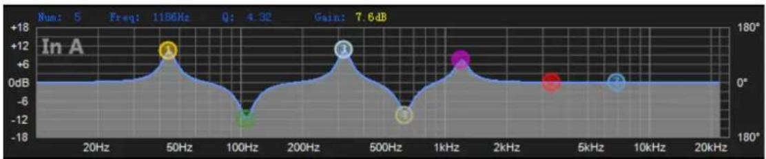
| Frequency | Value (dB) | Phase Angle (°) | | --------- | ---------- | --------------- | | 50Hz | +12 | 1186 | | 300Hz | +12 | 1186 | | 1kHz | +6 | 1186 | | 5kHz | +6 | 1186 | | 300Hz | +6 | 1186 |As shown in the figure above, it is used to control and display the current channel EQ curve. The corresponding multi-segment control points in the chart can be adjusted by clicking the left mouse button up, down, left, and right to adjust the EQ curve. Select the control point and press and hold the right mouse button to adjust the Q value.
7.4.4 EQ control parts
As shown in Figure 7.4 above, below the curve chart all the EQ control serial numbers and corresponding detailed values
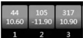
are displayed 1 2 3, which can be used to locate the position of the control. Combined with the following EQ parameter adjustment items, the parameter value of each EQ can be precisely adjusted.
7.4.5 EQ parameter adjustment items

As shown in Figure 7.4 above, below the EQ control is the EQ parameter adjustment item, which can accurately control the EQ switch, type, frequency, Q value, gain and other parameters. Filter types include PEQ parametric equalization, LSLV/HSLV high and low shelf, ALLPASS all-pass filter.
7.4.7 Preset button
As shown in Figure 7.4 above, when you click the EQ Preset button, the following EQ Preset will pop up
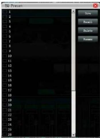
Select the preset item corresponding to the gear list on the left, and then click the function button on the right to realize the preset, recall, delete, and rename functions of the equalizer setting parameters. The preset parameters are saved to the computer in the designated folder in the software.
7.5 Dynamic EQ

Double-click in the module button DEQ, the following figure 7.5 input delay function interface will pop up.
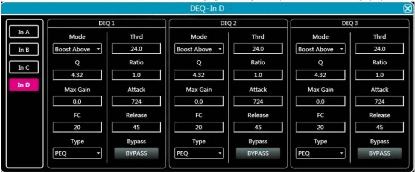
Figure 7.5 DEQ interface
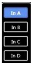
-
Click the input button to switch the input channel.
-
As shown in Figure, 4 kinds of DEQ modes: Boost Above, Boost Below, Cut Above, Cut Below, Max Gain.
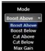
Figure. DEQ mode
-
Click to choose BYPASS type or PEQ type.
-
Threshold, Q value, Ratio, Max Gain, Attack, Frequency, and Release time for the DEQ corresponding parameters, which can be set by modifying the numeric box value.
7.6 Input delay

Double-click in the module button DELAY, the following figure 7.6 input delay function interface will pop up.
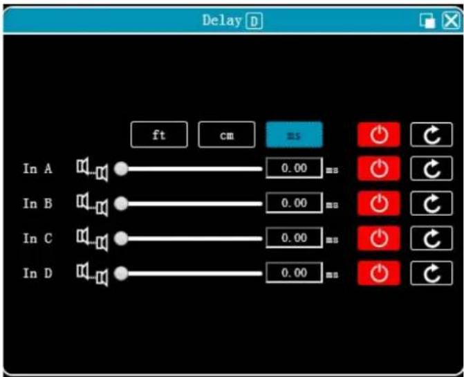
Figure 7.6 Input delay setting module
As shown above, the delay lists all input channels control content, drag the left slider. Can
directly adjust the delay value corresponding to the channel, box or value corresponding 6.73 ms to the input values, the right side of the switch delay function, Red is off, green is on, the reset button on the far right can directly reset the default value of the channel delay.
7.7 Input and output with FIR
Double-click in the function button
, and the following figure 7.6 FIR function page will pop up. Upper right
corner can zoom the interface.
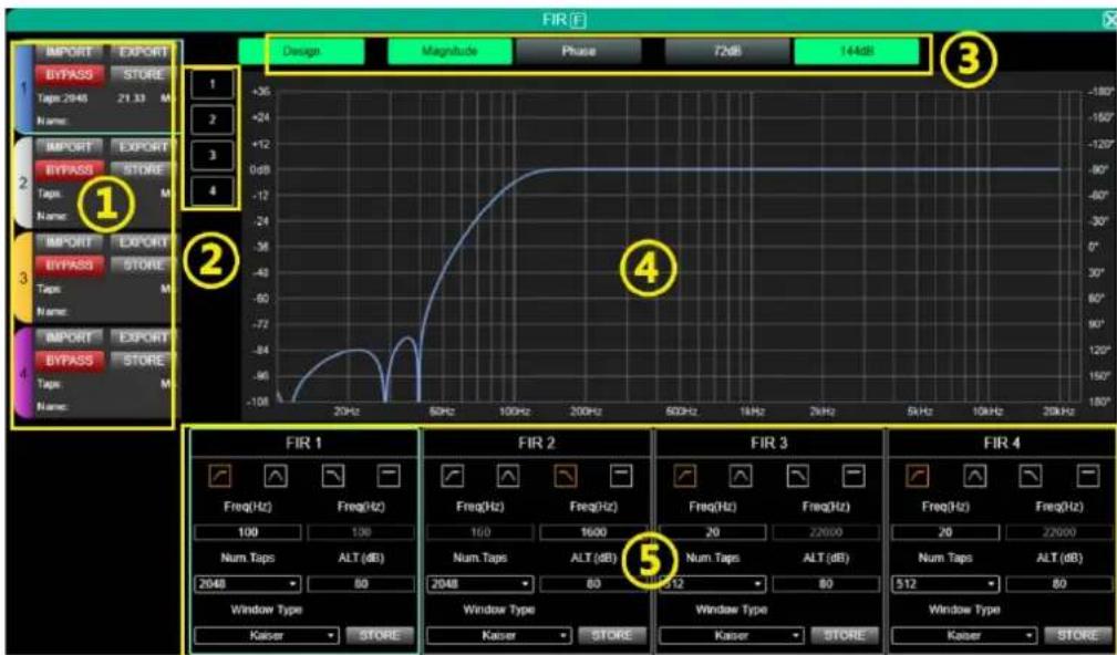
Figure 7.6 FIR setting module
Setting area:
- IMPORT: import FIR preset file to current channel.
- EXPORT: export FIR preset file of current channel.
- BYPASS: EQ is straight after bypass available, red for open, turn off manually when using FIR.
- STORE: store FIR parameters in the device.
● Taps: current Taps quantity - Ms: current delay
● Name: current name of FIR preset file
☐ Channels select: click and show current channel with FIR curve, support multiple channels.
Parameters select:
- Design: design switch button for interface.
● Magnitude: show magnitude curve.
● Phase: show phase curve. - 72dB: show content accuracy within 72dB amplitude.
● 144dB: show content accuracy within 144dB amplitude.
Curve area:
- -108□ +36: amplitude accuracy, the value used for reference when the current display is an amplitude curve.
- 180^ + 180^ : phase accuracy, the value used for reference when the current display is a phase curve.
- 20Hz□ 20kHz: bands.
□ Design area:

high pass, frequency band, low pass, flat.
- Freq(HZ): start frequency setting, high pass on the left, low pass on the right.
● Num.Taps: taps, 8 steps in total. optional 256-2048.
- ALT.(dB): depth, only available in Kaiser window.
● Windows Type: window type selection.
- STORE: click to save setting the parameters to the device channel.
7.8 Matrix mixing
Double-click in the function button
, and the following figure 7.8 matrix mixing function page will pop up.
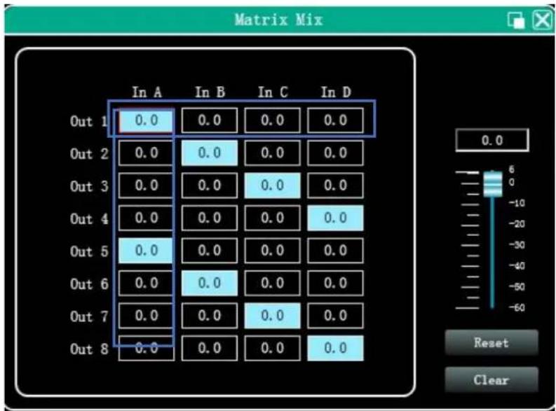
Figure 7.8 Matrix mixing setting module
In the above figure, the left side corresponds to the output channel, and the upper side corresponds to the input channel. The value box with a value is the input and output channel mixing key. When the mixing key is green (double-click the value box to switch the state), the input channel and output channel signal realizes the mixing function.
The right part of the above figure contains the gain, reset button, and clear button of the matrix mix. Click the value box on the left, and then drag the sliding block of the matrix mix gain or enter a value in the value box to adjust the matrix block. Click the reset button to reset the matrix mixing function to the initial one-to-one state; click the clear button to clear all the matrix mixing functions, and there is no correspondence between the input and output of the device.
7.9 Output Parametric Equalizer (PEQ)
![FEQ [E] - Out 1 Phase View Bypass Preset Copy Faste Reset Out 1 Out 2 Out 3 Out 4 Out 5 Out 6 Out 7 Out 8 +18 -12 -18 0dB -6 -12 -18 20Hz 50Hz 100Hz 200Hz 600Hz 1kHz 2kHz 6kHz 10kHz 20kHz +18 0° 0° 180° Out 1 20 346 0PF 1 2 3 4 5 6 7 23699 996 0PF LFF Freq (Hz) 20 EQ 1 Type Preq (Hz) Q Gain (dB) Type BW OK PEQ 50 4.32 0.0 Type BW](/content/2026/05/911247/images/4bb5d54e0c7c403975fc1bb4ba6cb45adf2f1856f42f0c6a15dcd690ab373920.jpg)
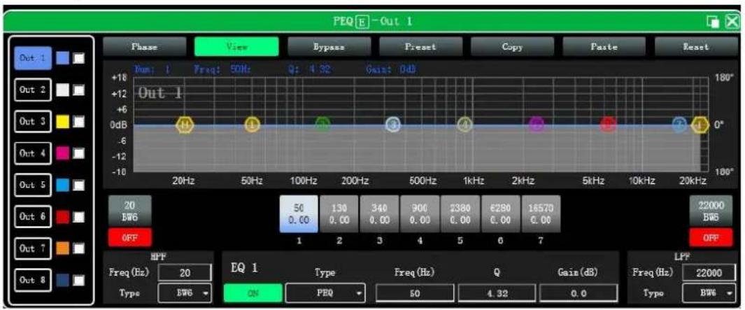
Figure 7.9 Output equalizer function interface
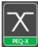
Double-click the function button PEQ-X, output equalizer function interface will pop-up shown in Figure 7.9, the parameter equalization function and operation mode are the same as input equalizer. But the output has increased the high and low pass filter function than the input, as described below.
7.9.1 EQ high and low pass filter
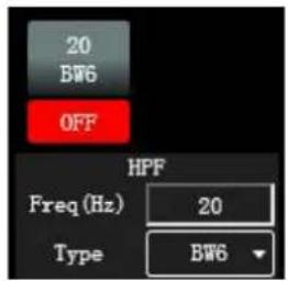
As shown above, high pass or low pass section in the lower right corner as shown in the left
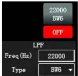
, you can control the switch, frequency and type of high pass and low pass, highest filter type slope
is 48dB.
7.10 Output delay
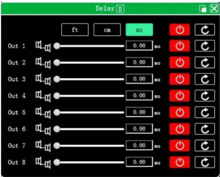
Figure 7.10 Output delay setting module

Double-click in the function button DELAY, and the output delay function interface shown in Figure 7.10 will pop up. The function and operation method are the same as input delay.
7.11 Output compressor

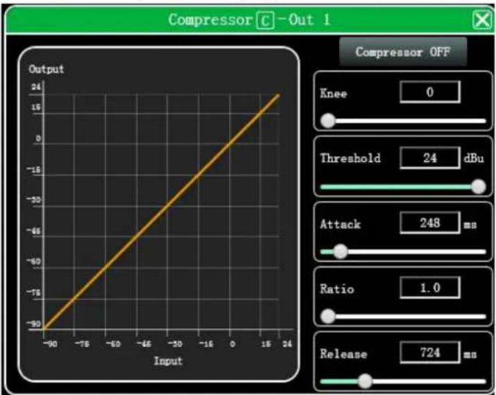
Double-click in the function button COMP, the following Figure 7.11 output compressor function interface pops up.
line
| Input | Output | |-------|--------| | -90 | -90 | | -76 | -76 | | -60 | -60 | | -46 | -46 | | -30 | -30 | | -16 | -16 | | 0 | 0 | | 16 | 16 | | 24 | 24 |7.11 Output compressor function interface
7.12 Output limiter

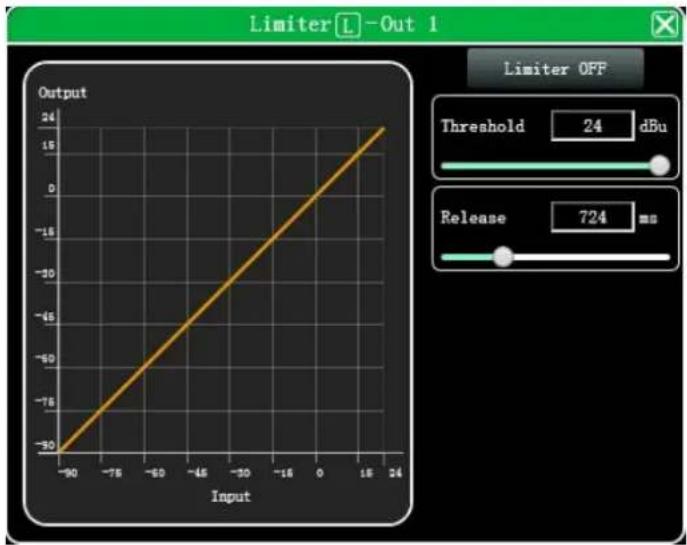
Double-click in the module button
, and the following Figure 7.12 output limiter setting module will pop up.
line
| Input | Output | |-------|--------| | -90 | -30 | | -75 | -75 | | -60 | -10 | | -45 | -15 | | -30 | -20 | | -15 | -25 | | 0 | -30 | | 15 | -35 | | 24 | -40 |Figure 7.12 Output limiter setting module
7.13 Output module
Double-click in the module button
and the output setting module shown in Figure 7.13 will pop up.
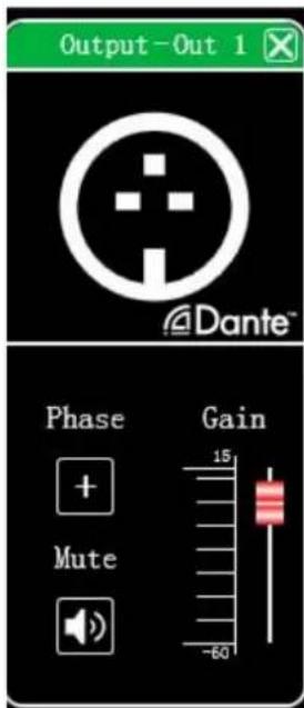
Figure 7.13 Output setting module
As shown in the figure above, you can control the polarity, mute, and gain settings of the corresponding output channel.
7.14 Input and output channel volume monitoring
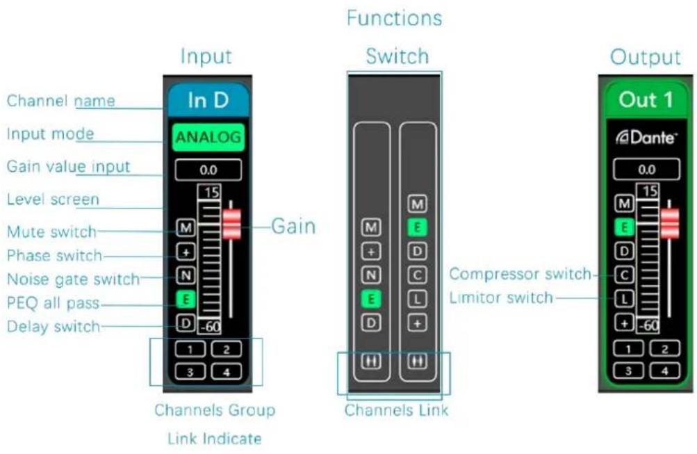
7.15 Channels link
Click the channels link button between the input and output channels on the software homepage, channels link interface will pop up as following Figure 13.1.
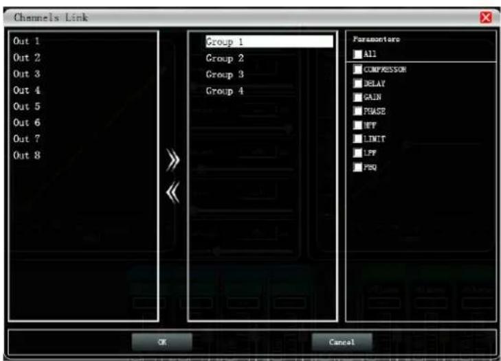
Figure 7.15 Channels link interface
As shown in the figure above, the three lists from left to right are divided into channel list, group list, and parameter list:
The channel list has listed all the channels that can be tuned together. After selecting the corresponding channel, click
the Add button to move to the group list.
After grouping the list of default four groups, directly select the corresponding packet, if the channel list will be added directly to the channel assigned to the selected group, to remove the optional channel to be removed by clicking the
Remove button below to add a button that is Can be removed to the channel list.
The parameter list is the parameters that can be adjusted jointly in the grouping list. When the check is ticked, it means that when the parameters of several channels in the same group are adjusted, other channels will make the same adjustment at the same time.
7.16 Device list
The device list on the software homepage, as shown in Figure 7.16 below.
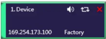
Figure 7.16 Device list interface
The above figure 1. shows the connected device numbers, which are automatically arranged in the order they are scanned; 1.Device is the device name, which can be changed at will, which is convenient for management; Factory
is the factory name (the user cannot modify it); if the connection method is TCP, the factory name will be left after the connection is connected. The side will display the IP address of the device; if it is in USB mode, it will display USB; if it is connected in serial port mode, it will display the specific COM port used;

From left to right, it is divided into mute button, disconnect/connect button, and remove device button.
The mute button can directly control the mute of all output channels of the entire device. If the device is online, the
leftmost position will turn green, The remove button can be used to remove the device directly in the software.
If you need to debug different devices, you can click to select the target device, and the function interface will switch to the device function page.
7.17 Add device
Click "File"- "New Device" in the menu bar of the main software interface, and the following Figure 7.17 Add Device Interface will pop up. Select the virtual device model to be added and add it to the device list. Note: The virtual device will not connect to the real device.
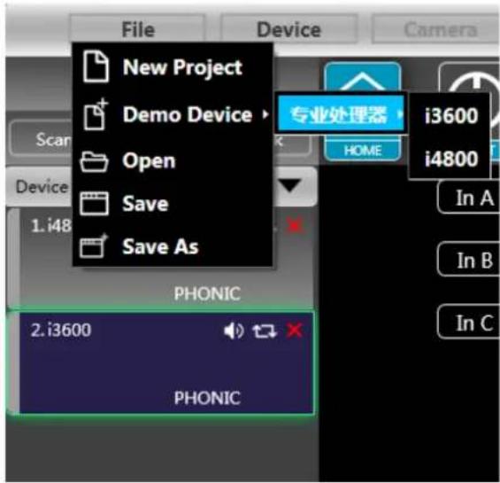
Figure 7.17 Add Device Interface
7.18 Device Management
Click "Device"- "Device" in the menu bar of the main software interface, and the device management interface shown in Figure 7.18 will pop up.
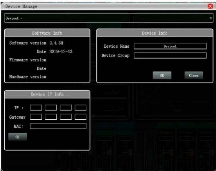
Figure 7.18 Device management interface
As shown in the figure above, the device information content displayed on the target device management interface can be selected in the device list at the top. The device management interface is divided into three parts as follows:
Software information: display the current device's upper and lower computer version number and date information.
Device information: display the current device name and device grouping, among which "device name" can be entered in the new name and then click the button to save.
Device IP information: If the current device is connected with network information, the IP address, gateway, and MAC address of the device will be displayed here. The IP and gateway can be modified and click the OKbutton to save and restart the device network module, which newly entered network information will take effect immediately.
7.19 Channel name management
Click "Device"- "Channels Names" in the menu bar of the main software interface, and the following Figure 7.19Channel Name interface will pop up.
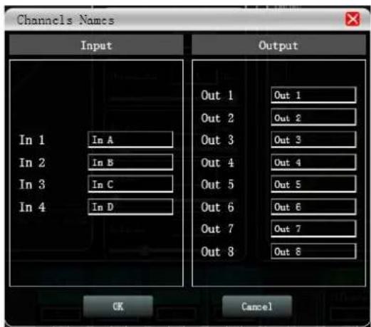
Figure 7.19 Channels name management
As shown in the figure above, after entering the new name of the channel in the corresponding channel, click the OK button to save and update the name of the channel immediately. Note that the length of the channel name is limited to 5 English letters and numbers.
7.20 Channels copy
Click "Device"- "Channels Copy" in the menu bar of the main software interface, and the following Figure 7.20 Channels Copy interface will pop up.
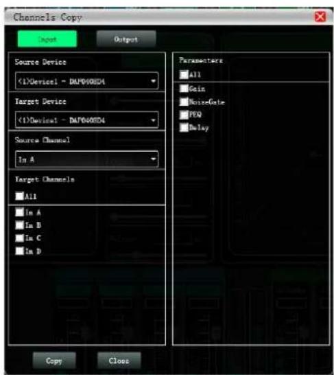
Figure 7.20 Channel Copy interface
As shown in the figure above, channel copy is to first select the source channel parameters of a source device and copy them to the target channel of the same device or other target devices. Input channels and output channels cannot copy each other. The left side is the corresponding channel, and the right side is the parameter to be copied. The "input" and "output" buttons at the top of the interface can switch the channel type for copying.
7.21 Device Preset
Click "Preset" in the menu bar of the main interface of the software, and the device preset interface in Figure 7.21 will pop up.
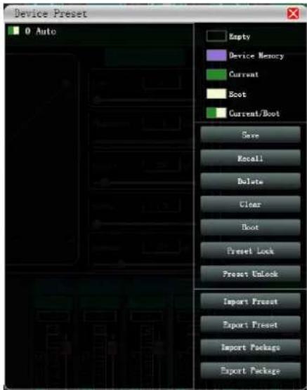
Figure 7.21 Device Preset interface
As shown in the above picture, the left side of the preset interface is the gear position, among which "0 automatic gear" is the system gear position, which automatically saves all parameters; "1 (default)" is the default file of the device, which can only be recalled, and cannot be deleted or overwritten. The parameters will all be restored to the factory default parameters; other gears can be freely saved, recalled, deleted and other operations.
The function buttons on the right side of the preset interface are as follow:
Save: Save the existing device parameters to the corresponding selected preset.
Recall: Recall the selected preset to the current parameters of the device.
Delete: delete the selected preset parameter.
Clear: Clear all preset parameter records that are not preset by the system.
Set as boot file: Set the selected gear as the boot file, and each time the power is turned on, the boot file will be automatically called and all the parameters of the preset will be automatically used to work.
Import and preset: Import a single device parameter file in the computer system, and directly overwrite the existing parameter data.
Export and preset: save the current equipment parameters to the computer system to produce a single equipment parameter preset file
Import preset package: import multiple preset parameter packages in the computer system
Export preset package: Export the parameters of all gears in the equipment preset to the computer system to produce multiple preset parameter package files.
7.22 Firmware upgrade
Click "System" - "Upgrade" in the menu bar of the main software interface, and the firmware upgrade interface shown in Figure 7.22 will pop up.
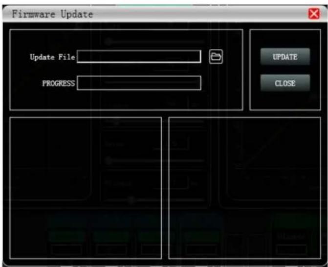
Figure 7.22 Firmware Upgrade interface
When the lower computer system of the device has been updated, after obtaining the upgrade file, you can open the firmware upgrade interface as shown in the figure above. After selecting the corresponding upgrade file in the "Upgrade File" column, click "UPGRADE" in the upper right corner, and the system will automatically start upgrade operation as well as transfer upgrade file to the lower device, and the operation log is displayed in the progress box below. After the upgrade is completed, the machine will restart automatically or manually restart the machine to complete the upgrade.
Chapter 8 Introduction to Dante
The device can be equipped with a Dante module. Dante digital network audio technology is an uncompressed professional-grade digital audio transmission technology (AoIP) based on Ethernet network transmission. Dante technology supports digital audio signal network transmission in audio systems even up to Dozens of units are set with hundreds of units to realize the interconnection and intercommunication of digital signals between devices, and have a stable and reliable signal synchronization function.
Dante system construction
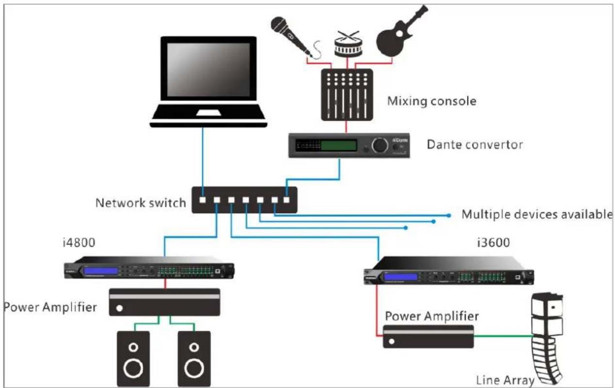
flowchart
graph TD
    A["Laptop"] --> B["Network switch"]
    C["Mixing console"] --> B
    D["Dante converter"] --> B
    B --> E["i4800"]
    B --> F["i3600"]
    B --> G["Power Amplifier"]
    B --> H["Line Array"]
    I["Power Amplifier"] --> B
    J["Power Amplifier"] --> B
    K["Line Array"] --> B
    L["Multiple devices available"] --> B
Dante Controller routing configuration
Dante Controller is a software application provided by Audinate that allows users to configure and route audio signal on a Dante network. It is available for Windows and OS X. After installing Dante Controller on your PC or Mac, you be able to manage all Dante devices. Dante Controller software can be downloaded for free on the official website
www.audinate.com.
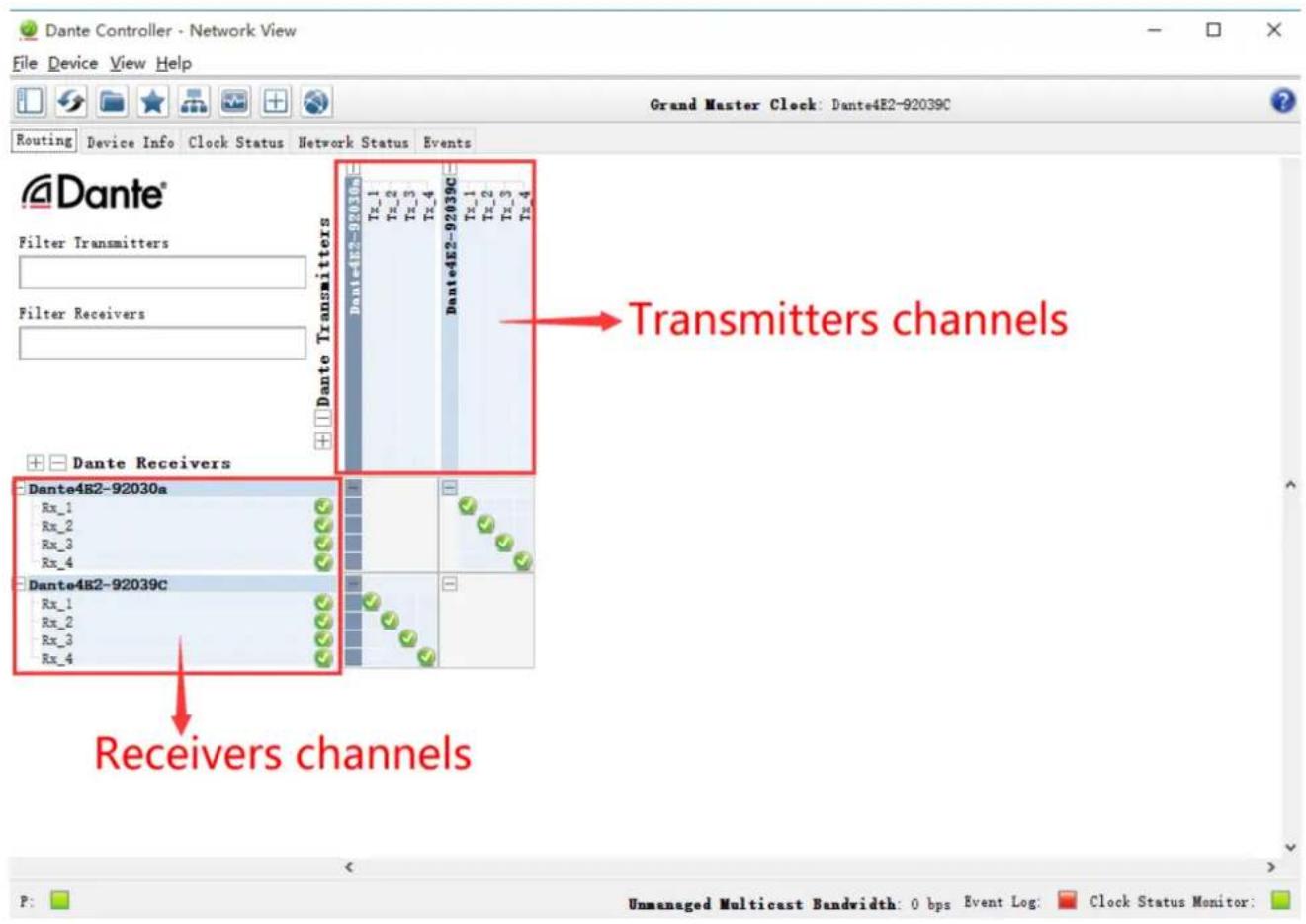
After the routing configuration, Dante will memorize its own routing configuration. After turning off the power and restarting, Dante routing will restore itself. There is no need to configure the computer again. At this time, the Dante Controller control software can be closed.
- Professional Audio Processor
- Index
- Chapter 1: Introduction
- Applications
- Chapter 2: Technical Parameters
- Features
- Technical Parameters
- LCD display function menu
- Control buttons
- Input section
- Output section
- Chapter 4: Introduction to PC Software
- Chapter 5: Software Installation
- Operating environment
- Software installation
- Software operating
- Chapter 6 Software Interface Description
- Introduction to Interface Module
- Menu bar
- Scan button
- Set button
- Linkbutton
- Device list
- Computer IP address
- Function control keys
- Function module interface
- Input and output channel volume monitoring
- Chapter 7 Function Interface Introduction
- Main interface of input function
- Test signal function
- Input noise gate
- Input Parametric Equalizer (PEQ)
- Function buttons
- Multi-channel EQ curve display
- EQ curve chart
- EQ control parts
- EQ parameter adjustment items
- Preset button
- Dynamic EQ
- Input and output with FIR
- Matrix mixing
- Output Parametric Equalizer (PEQ)
- Output compressor
- Output limiter
- Output module
- Input and output channel volume monitoring
- Channels link
- Device list
- Add device
- Device Management
- Channel name management
- Channels copy
- Device Preset
- Firmware upgrade
- Chapter 8 Introduction to Dante
- Dante Controller routing configuration
Brand : PHONIC
Model : i4800
Category : Uncategorized