
132WS - Sensor JUNG - Free user manual and instructions
Find the device manual for free 132WS JUNG in PDF.


| Product Type | Motor control insert for blinds/shutters (Jalousie Management Direkt) |
| Brand | JUNG |
| Model | 132WS |
| Rated Voltage | AC 230 V ~, 50 Hz (neutral conductor not required) |
| Switching Capability | Max. 1 motor, 1000 W |
| Relay Output | 2 non-floating normally open contacts (mutually interlocked) |
| Pulse Time (manual/radio/memory attachments) | 2 minutes |
| Pulse Time (timer attachment universal) | Programmable: 1 second to 12 minutes (default 2 minutes) |
| Minimum Switch-Over Time (continuous run) | Approximately 1 second |
| Compatible Attachments | JM push-button, radio receiver, push-button with memory, timer standard/universal (with or without sensor input) |
| Sensor Input | For sun protection/twilight sensor (art. no. 32 SD) and glass breakage sensor (art. no. 32 G) via 3-pole terminal block |
| Connecting Terminals | Screw terminals for max. 2.5 mm² or 2 x 1.5 mm² |
| Mounting | In mounting box according to DIN 49073 (deep box recommended) |
| Circuit Breaker | Max. 16 A |
| Safety | Installation only by qualified electrician; only for motors with limit switches and max. 1000 W; do not use isolating relays |
| Maintenance | No specific maintenance required; clean with dry cloth if needed |
| Spare Parts / Repairability | Return to manufacturer for service; contact JUNG Service-Center |
| General Information | Part of Jalousie Management system; designed for automatic operation of window blinds and shutters |
Frequently Asked Questions - 132WS JUNG
User questions about 132WS JUNG
0 question about this device. Answer the ones you know or ask your own.
Ask a new question about this device
Download the instructions for your Sensor in PDF format for free! Find your manual 132WS - JUNG and take your electronic device back in hand. On this page are published all the documents necessary for the use of your device. 132WS by JUNG.
USER MANUAL 132WS JUNG
1. Safety instructions
Attention: Electrical equipment must be installed and fitted by qualified electricians only.
Only for connection of a motor with limit switches and a power consumption of max. 1000 W. Non-observance of the fitting instructions may damage the device and cause fire or other hazards.
The blind/shutter control is designed for the automatic operation of window blinds and shutters. Any other use as, for instance, the operation of roller-shutter gates may involve hazards. These risks must be excluded by the user by providing supplementary and suitable safety devices (e.g. light barriers).
2. Function
The motor control insert 'Direkt' is used in electrical installations without neutral conductor (N).
The existing mechanical shutter switch can therefore be replaced directly by a comfortable control unit with the motor control insert 'Direkt'. The motor control insert 'Direkt' is a component of the Jalousie Management and is used in conjunction with attachments of the Jalousie Management in a mounting box acc. to DIN 49073 (deep box recommended).
By replacing the attachment it is therefore possible to realize systems with manual operation, comfortable operation by radio remote control or timer-controlled fully automatic operation.
The insert is equipped with two mechanically interlocked relay power contacts. The simultaneous activation of both moving directions of the shutter motor connected is thus excluded. connected is thus excluded.
Attention: Connect only one motor with limit switches and a power consumption of 1000 W max. to each insert. Do not use isolating relays. It is absolutely necessary to check the motor for suitability as described in chapter 4.

Jalousie Management JM Motor Control Insert Direkt
Ref.-no.:
The insert has 3 connecting terminals (1) and a 6-pole interface connector (2) for connection of the attachment. In addition, a 3-pole terminal block (3) can be placed into the insert (supplied with inserts with sensor input).
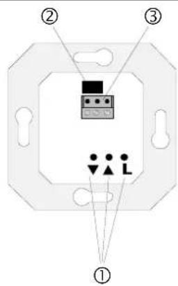
This terminal block can be used to connect different sensors to the insert when attachments with sensor input are installed:
• Sun protection / twilight sensor (art. no. 32 SD)
• Glass breakage sensor (art. no. 32 G)
2.1. Equipment combinations
Depending on the attachment used, the following functions can be implemented:
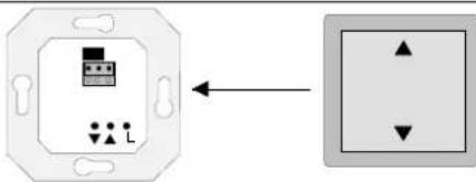
JM push-button attachment, (Art. no. ..5232 .., ..5252 S..)
Pushbutton for manual operation.
(see 'JM push-button attachment' operating instructions).
natural_image
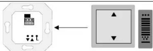
Diagram showing a wall-mounted component with a small inset image and a square layout with four directional arrows (no text or symbols)JM radio receiver attachment, (Art. no. ..5232 F., ..5252 FS..)
Pushbutton for manual and radio remote-control operation (see 'JM radio receiver attachment' operating instructions).
JM push-button attachment with memory function,
(Art. no. ..5232 M., ..5252 MS..)
Jalousie Management JM Motor Control Insert Direkt
Ref.-no.:
Pushbutton for manual operation with additional automatic control. With its memory function for an UP and a DOWN movement, this attachment permits simple and individual programming. Both shutter movement times are repeated once every 24 hours (see 'JM pushbutton attachment with memory function' operating instructions)
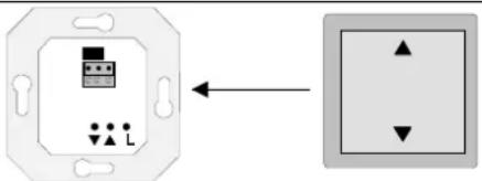
If the above attachments are used in the versions with sensor input, the glass breakage alarm and sun protection functions can also be implemented.
JM timer attachment standard or JM timer attachment universal
Timer for automatic control with programmable switching times. See also the operating instructions of: JM timer attachment standard (Art. no. ..5232 ST..) and
JM timer attachment standard (Art. no ..5232 ST..)
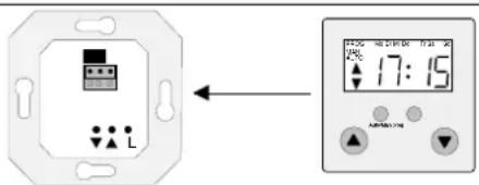
and JM timer attachment universal Art no. ..5232 T., ..5232TS..
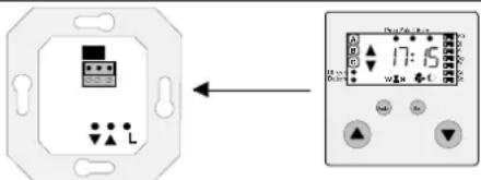
When the versions with sensor input are used, the following functions are available in addition:
- glass breakage alarm
- sun protection function
- twilight function
3. Instructions
Use blind/shutter motors with mechanical or electronic limit switches only.
Check the blind/shutter motor for suitability in compliance with the instructions set out in chapter 4 before using it in conjunction with the JM motor control insert 'Direkt'.
Do not use isolating relays. With such relays, the blind/shutter control has no power supply through the motor winding. Risk of malfunction.
Observe the instructions of the motor manufacturers concerning the switchover time and the maximum load factor (c.d.f.)
The JM motor control insert 'Direkt' must only be used in conjunction with one of the following attachments:
• JM push-button attachment
• JM radio receiver attachment
- JM push-button attachment with memory function
• JM timer attachment standard
• JM timer attachment universal
The electronic interlocking of the attachment permits to obtain a minimum switch-over time of approx. 1 second in the continuous run mode.
If a shutter motor is to be activated or deactivated – besides by local operation – also from higher-level systems (e.g. centralized control), the motor control insert JM with inputs for extension controls must be used (neutral wire required).
If it is necessary to prolong the sensor line, use an appropriate type of sensor cable. Recommendation: J-Y(ST)Y 2x2x0.6 mm.
Often, it is not known whether the motor installed is equipped with mechanical or electronic limit switches.
Therefore: Check the motor first for suitability. Some motors with mechanical limit switches tend to build up a high motor voltage in operation which may irreparably damage the JM motor control insert 'Direkt'. Checking is therefore effected with a commercial mechanical shutter switch (possibly still installed) and not with the JM motor control insert 'Direkt'.
Carry out the following measurement using a voltmeter:
• Measure the actual mains voltage UN.
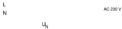
M
U_M
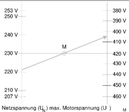
- Go to the measured mains voltage on the left side of the diagram opposite.
Jalousie Management JM Motor Control Insert Direkt
Ref.-no.:
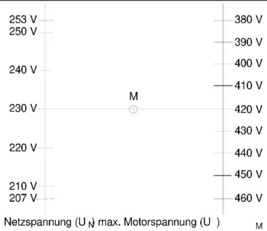
scatter
| Voltage (V) | Max Motor Spannung (U) | |---|---| | 253 | 380 | | 250 | 390 | | 240 | 400 | | 230 | 410 | | 220 | 420 | | 210 | 430 | | 207 | 440 | | 210 | 450 | | 207 | 460 | Netzspannung (U_N) max. Motorspannung (U) M- Draw a straight line from the value found through the center M to the righthand axis. The intersection of the line and the right axis is the maximum permissible motor voltage UM.
- Measure the motor voltage UM in the UP and DOWN direction on the installed mechanical shutter switch. The maximum value as determined above must not be exceeded when the measurements are made.
Example:
The measured mains voltage UN is 221 V. Draw a straight line from 221 V on the left through the center of the diagram (M) to the right side with motor voltage UM. The maximum permissible motor voltage in this case is 404 V. The voltages measured for the UP and DOWN directions must therefore be below 404 V.
line
| Netzspannung (U_N) max. Motorspannung (U) | 253 V | 250 V | 240 V | 230 V | 220 V | 210 V | 207 V | |---|---|---|---|---|---|---|---| | Motorspannung (U) | 380 V | 390 V | 400 V | 410 V | 420 V | 430 V | 440 V | | Max. Motorspannung (U) | 460 V | 450 V | 450 V | 450 V | 440 V | 430 V | 420 V |Approximate values for typical maximum motor voltages UM as a function of the mains voltage UN are set out in the table opposite.
| UN | max. |
| 207 V 380 V | |
| 215 V 393 V | |
| 220 V 403 V | |
| 225 V 412 V |
UM
Jalousie Management JM Motor Control Insert Direkt
Ref.-no.:
| 230 V 420 V | |
| 235 V 429 V | |
| 240 V 438 V | |
| 245 V 447 V | |
| 253 V 460 V |
Motor with electronic limit switches
If it is certain that the motor used is one with electronic limit switches, the measurement described above can be dispensed with.
It is not possible to damage the insert with motors equipped with electronic limit switches if these are used in conformity with their designated use.
In this case, check the basic functions of the motor in combination with the JM motor control insert 'Direkt' as follows:
- Install the JM motor control insert 'Direkt' as described in chapter 5.
- Plug a shutter control attachment into the insert.
- Test the functions of the shutter control in several trial runs with the motor connected.
4. Connection and fitting
The JM motor control insert 'Direkt' is connected in acc. with the opposite figure.
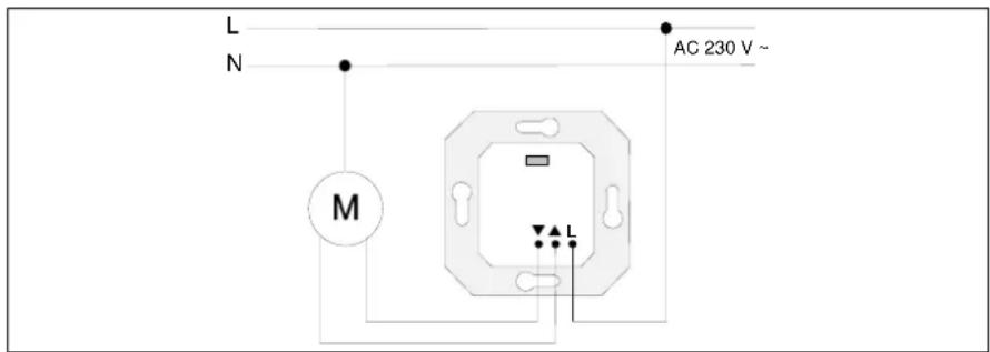
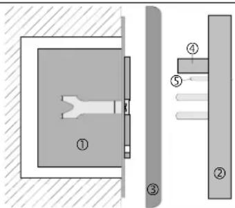
Install the JM motor control insert 'Direkt' (1) in a mounting box in acc. With DIN 49073 (deep box recommended). The conecting terminals of the insert must be at the bottom.
Plug the attachment (2) together with frame (3) into the insert.
The electrical contact is established through connector (4).
The additional contact pins (5) in attachments with sensor input make automatic contact with the 3-pole terminal block placed into the insert.
Jalousie Management JM Motor Control Insert Direkt
Ref.-no.:

6. Installation with sensors
Important: The sensor cable carries safety extra low voltage (SELV). Observe the installation rules in acc. with VDE 0100.
The installation of the sensors varies with the type of installation (flushmounting or surface-mounting) and with the attachment used. The sensor cable is factory-equipped with a connector.
Direct connection of the sensor cable to the attachment
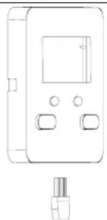
If the attachment is equipped with a jack, the sensor is simply connected to the attachment by plugging the connector into the jack. The connector is polarized so that it can be plugged in only in the correct position (see attachment operating instructions).
natural_image
Line drawing of a device with ports and a connector (no text or symbols)Flush-mounting installation of sensor cable
The sensor cable is laid in a cable duct inside the insert.
- Cut off the connector at the end of the sensor cable.
- Slide the insulating sleeve (supplied with attachments with sensor input) over the sensor cable.
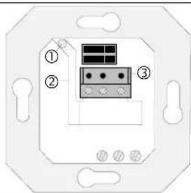
- Stick the sleeved cable through the hole (1) of the insert. The insulating sleeve must cover the sensor cable over the full length from the flush-mounting box to the cable duct (2).
- Pass the cable with the insulating sleeve through the duct (2) to the terminal block (3). The cable must follow the duct closely without any loops in the 230 V section of the insert.
- Place the terminal block (supplied with attachments with sensor input) into the insert as shown in the illustration (screws at the bottom).
Jalousie Management JM Motor Control Insert Direkt
Ref.-no.:
Surface-mounting of sensor cable, version 1
The cable is passed through the cable duct in the insert.
- Pass the the sensor cable (1) through opening (2) behind the supporting frame (between wall and supporting frame) into the cable duct (3) in the insert.
- Lead the cable directly through the duct to the terminal block (4). The cable must follow the duct closely without any loops in the 230 V section of the insert.

Connection to the terminal block in the insert:
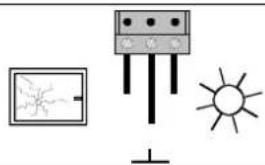
Connect the sensor cable in acc. with fig. E. The screws of the block must be at the bottom.
Left: glass breakage sensor signal line Center: ground Right: sun / twilight sensor signal line
Wire marking:
Sensors: 'Ground' = marked grey
Adapter and extension cable: 'Sun' = marked grey "Ground" = middle wire
natural_image
Simple line drawing of a solar panel, a screen with a crack, and a sun (no text or symbols)If the the sun / twilight sensor and the glass breakage sensor are to be used at the same time, an adapter must be installed (to be ordered
separately). Connect the adapter directly to the attachment by means of the connector or to the insert with the 3-pole terminal block (connector cut off). The adapter is equipped with 2 jacks for connection of the sensor plugs
5. Technical data
Rated voltage: AC 230 V \~, 50 Hz
N-conductor not required
Switching capability: max. 1 Motor 1000 W
Relay output: 2 non-floating n.o. contacts (mutually interlocked)
Pulse time
JM push-button attachment 2 minutes
JM push-button attachment with
memory function: 2 minutes
JM radio receiver attachment: 2 minutes
JM timer attachment standard 2 minutes
JM timer attachment universal standardwert 2 minutes programmed :1 second - 12 minutes
Switch-over in continuous run mode: min. 1 second
(electronic interlock in attachment)
Connecting terminals:
screw terminals for 2.5 mm ^4 max.
or 2 x 1.5 mm²
Circuit-breaker
16 A max.
6. Guarantee
We accept the guarantee in accordance with the corresponding legal provisions.
Please return the unit postage paid to our central service department giving a brief description of the fault:
ALBRECHT JUNG GMBH & CO. KG
Service-Center
Kupferstr. 17-19
D-44532 Lünen
Service-Line: 0 23 55 . 80 65 51
Telefax: 0 23 55.80 61 89
instabus EIB equipment
Service-Line: 0 23 55.80 65 56
Telefax: 0 23 55.80 62 55
CE The CE-sign is a free trade sign addressed exclusively to the authorities and does not include any warranty of any properties.
- Safety instructions
- Function
- Jalousie Management JM Motor Control Insert Direkt
- Equipment combinations
- JM timer attachment standard or JM timer attachment universal
- Instructions
- Example:
- Motor with electronic limit switches
- Connection and fitting
- Installation with sensors
- Direct connection of the sensor cable to the attachment
- Flush-mounting installation of sensor cable
- Surface-mounting of sensor cable, version 1
- Connection to the terminal block in the insert:
- Wire marking:
- Technical data
- Guarantee
- Please return the unit postage paid to our central service department giving a brief description of the fault:
- instabus EIB equipment
Brand : JUNG
Model : 132WS
Category : Sensor