
WS10KS - Sensor JUNG - Free user manual and instructions
Find the device manual for free WS10KS JUNG in PDF.


| Product Type | Combination Sensor |
| Brand | JUNG |
| Model | WS10KS |
| Dimensions (Diameter x Height) | 130 x approx. 200 mm (without bracket) |
| Weight | Approx. 330 g (without stainless steel bracket) |
| Power Supply | 24 V AC/DC ±15%, 50/60 Hz |
| Max. Current Consumption | 600 mA |
| Power Consumption | 14.4 W max. (sensors and heating) |
| Protection System | IP55 (in working position) |
| Protection Class | III |
| Ambient Temperature | -40°C to +60°C (ice-free) |
| Connecting Cable | 6 x 0.25 mm² shielded, 10 m (max. 50 m extension) |
| Measured Parameters | Wind speed, precipitation, brightness (E/S/W), twilight |
| Brightness Measuring Range | Approx. 0–110 kilolux |
| Twilight Measuring Range | Approx. 0–674 lux |
| Wind Speed Sensitivity | Fine drizzle |
| Precipitation Switch-on Delay | Approx. 3 precipitation particles |
| Precipitation Switch-off Delay | Approx. 2 minutes |
| Heating | Integrated for frost-free operation |
| DCF77 Receiver | Optional (model WS 10 KSDCF) |
| Mounting | On tubular mast (∅35–50 mm) with stainless steel bracket |
| Minimum Distance from Wall | 0.5 m |
| Guarantee | Statutory provisions |
Frequently Asked Questions - WS10KS JUNG
User questions about WS10KS JUNG
0 question about this device. Answer the ones you know or ask your own.
Ask a new question about this device
Download the instructions for your Sensor in PDF format for free! Find your manual WS10KS - JUNG and take your electronic device back in hand. On this page are published all the documents necessary for the use of your device. WS10KS by JUNG.
USER MANUAL WS10KS JUNG
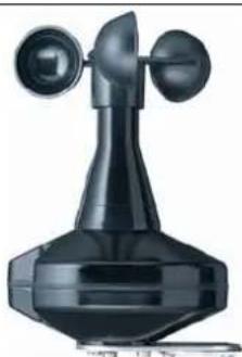
Operating Instructions Combination sensor
natural_image
Black industrial-style telephone receiver with two dials and a bell (no visible text or symbols)1. Safety warnings

Attention:
Electrical equipment must be installed and fitted by qualified electricians only and in strict observance of the relevant accident prevention regulations. Failure to observe any of the installation instructions may result in fire and other hazards.
2. Function
- The combination sensor can measure wind speed, precipitation brightness and twilight. Brightness can be measured separately for the cardinal points East, South and West.
- The combination sensor can be directly connected to a weather station (e.g. Art. no. 2224 REG W) which ensures further processing of th measured data and transmission to the bus in the form of switching or value telegrams. Bus subscribers as, for instance, the Info-Display ..2041.., the „Facility-Pilot“ visualization software and the LCD annunciator and control panel MT 701 can thus intervene into control processes, generate messages, or control weather-dependent processes. Resulting applications are in building services management control engineering, greenhouse control, or in further processing of the collected data in control and operating units.
- The combination sensor Art. no. WS 10 KSDCF is equipped with DCF77 receiver which can receive the legal German time and transmit the signals to the KNX/EIB bus (e.g. to synchronize KNX/EIB clocks).
- To ensure trouble-free service even in case of frost, the combination sensor can be heated.
- The combination sensor needs an external 24 V power supply, Art. no. WSSV10.
3. Installation
Important: Combination sensor with DCF77
Check the place of installation for optimal reception of the DCF77 time signal. Reflexions can cause reception interference. If no interference-free reception is possible, change the place of installation by a few meters until the combination sensor receives the time signal without interference (see chapter „Antenna orientation“).
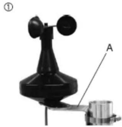
- For installation on a tubular mast (∅ 35 ... 50 mm), a stainless-steel mounting bracket is supplied with the sensor (FIG.(1) .
- The combination sensor must be installed unobstructed by obstacles in all directions.
natural_image
Mechanical device with labeled component A, no visible text or symbols on the device itself- When the combination sensor is installed in front of a wall, a minimum spacing of 0.5 m must be respected to prevent incorrect measuring values due to negative influence on the sensors.
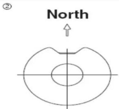
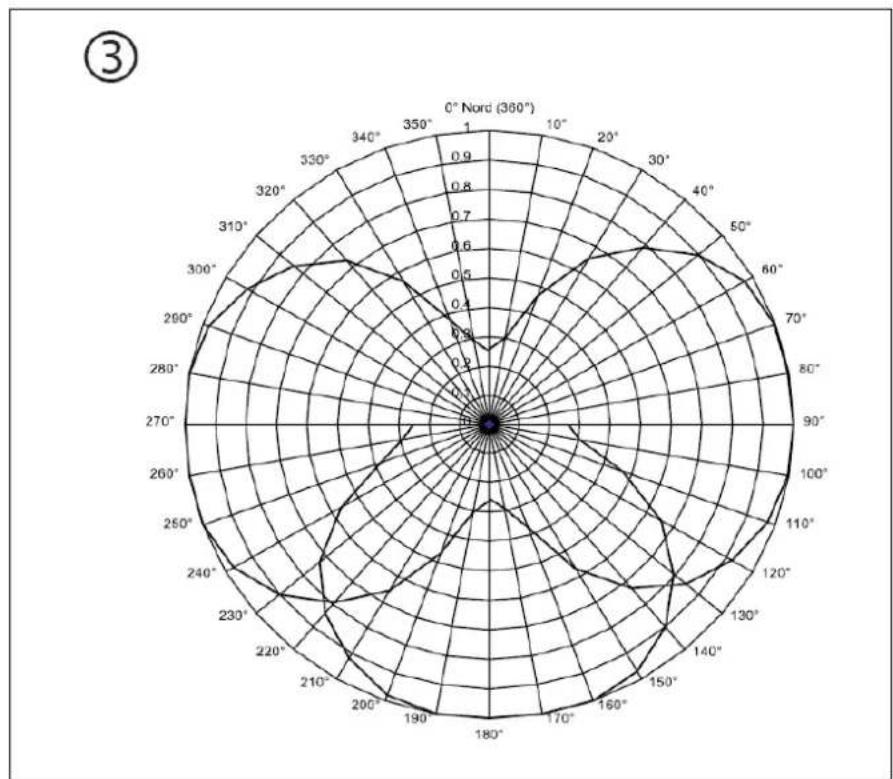
- To enable the brightness sensors to clearly determine the sun's actual position, the combination sensor must be aligned with the help of a compass in such a way that the precipitation window points to the North (see FIG. 2). In this case, the brightness sensors are correctly aligned with the cardinal points (FIG.3).
- To ensure perfect wind speed measurements, the wind wheel must be able to turn freely. This can be checked visually at low wind speeds.
- To ensure perfect wind speed measurements, the wind wheel must be able to turn freely. This can be checked visually at low wind speeds.
- The part of the enclosure where the brightness and precipitation sensors are located (side and top of the device) should be free from dust deposits to avoid incorrect measuring values. In operation, rainfall is mostly sufficient to clean the enclosure surfaces.
radar
| Angle (°) | Value | | --------- | ----- | | 0° | 0.0 | | 350° | 0.8 | | 70° | 0.6 | | 105° | 0.4 | | 140° | 0.2 | | 175° | 0.1 | | 210° | 0.3 | | 245° | 0.5 | | 280° | 0.7 | | 315° | 0.9 | | 350° | 0.8 | | 385° | 0.6 | | 420° | 0.4 | | 455° | 0.2 | | 500° | 0.1 | | 535° | 0.3 | | 570° | 0.5 | | 605° | 0.7 | | 640° | 0.9 | | 675° | 0.8 | | 710° | 0.6 | | 745° | 0.4 | | 780° | 0.2 | | 815° | 0.1 | | 850° | 0.3 | | 885° | 0.5 | | 920° | 0.7 | | 955° | 0.9 | | 1000° | 0.8 | | 1035° | 0.6 | | 1070° | 0.4 | | 1105° | 0.2 | | 1140° | 0.1 | | 1175° | 0.3 | | 1210° | 0.5 | | 1245° | 0.7 | | 1280° | 0.9 | | 1315° | 0.8 | | 1350° | 0.6 | | 1385° | 0.4 | | 1420° | 0.2 | | 1455° | 0.1 | | 1490° | 0.3 | | 1525° | 0.5 | | 1560° | 0.7 | | 1595° | 0.9 | | 1630° | 0.8 | | 1665° | 0.6 | | 1700° | 0.4 | | 1735° | 0.2 | | 1770° | 0.1 | | 1805° | 0.3 | | 1840° | 0.5 | | 1875° | 0.7 | | 2000° | 0.9 | | Note: The data is in a grid format with 'Nord' label at the top center.3.1. Connection
- The combination sensor is provided with a 10 m-long connecting cable. The cable may be extended up to 50 m max. (recommended cable: LiYCY 6 x 0.25 mm _2 , shielded).
Connect the combination sensor to the weather station (FIG. 4):
(a) pink : supply AC/DC 24 V, 600 mA
(b) grey : supply ground
(c) green-yellow : shield
(1) green : system voltage DC 24 V, > 15 mA
(2) yellow : data
(3) white : sync.
(4) brown : system ground
④
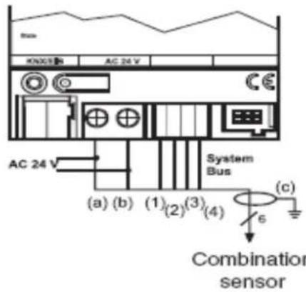
- If possible, connect the shield of the combination sensor (yellow-green, (c)) to earth potential (not to GND!). If this is not feasible, the shield must remain unconnected. When the shield is connected with GND, trouble-free operation of the device cannot be guaranteed.
4. Commissioning
Commissioning includes logging in of the combination sensor at the weather station and pointing of the antenna for best reception. This can be done without a project and before final installation (e.g. at the workshop).
Log-in of the combination sensor
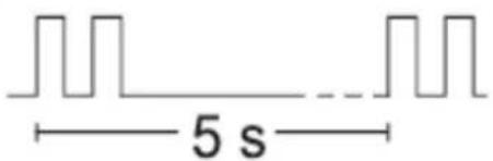
- Switch on the power. The combination sensor confirms that it is ready for operation by two brief tones repeated every 5 s (FIG. 5).
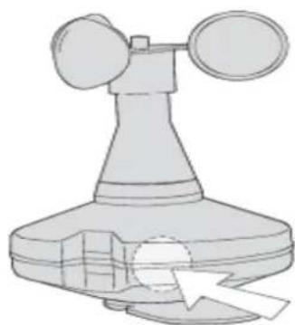
- Log in the combination sensor at the weather station. Hold the magnet supplied with the device against the integrated Reed contact (FIG. 6) so that 5 brief tones will be heard (FIG. 7). The combination sensor is now transmitting data to the weather station.
- Weather station and combination sensor will now be reset. The combination sensor confirms this action by a brief tone.
⑤
KNX Combination sensor
Ref.-no.: WS 10 KS, WS 10 KS DCF
⑥
natural_image
Illustration of a weather instrument with two fans and a base, showing airflow or pressure direction (no text or symbols)4.1. Antenna orientation
Combination sensor with DCF77 receiver, part no. WS 10 KSDCF After log-in of the combination sensor, check the reception of the DCF77 time signal at the weather station.
⑧
⑨
natural_image
Close-up of a mechanical component with metallic parts and a white arrow pointing to a feature (no visible text or symbols)- Hold the magnet supplied with the device against the integrated Reed contact (FIG. 6) so that 5 brief tones will be heard (FIG. 7). Hold the magnet in this position.
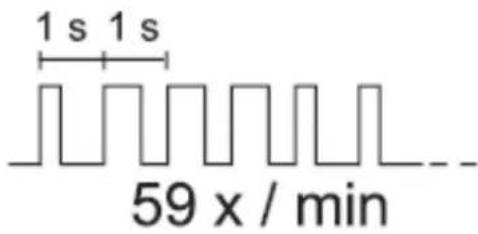
- The combination sensor indicates reception of the time signal by brief tones (at 1-second intervals; interruption after each full minute) (FIG. 8).
- Important: The quality of the time signal is independent of tone length.
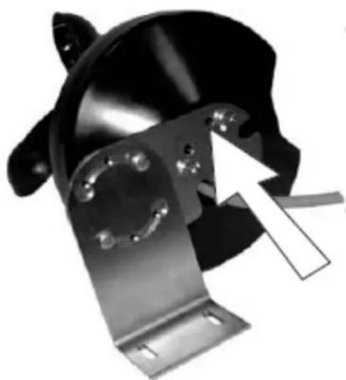
- If the tones are heard only irregularly or not at all, the receiving antenna must re-orientated. The antenna is accessible from the underside of the combination sensor (FIG. 9). The antenna can be turned through 45°. Turn the antenna with a screwdriver until a brief tone signal is heard every second.
- Important: If – after re-orienting the antenna – the reception is still not good enough, install the device at another location.
- Take the magnet away from the sensor. The combination sensor confirms the removal with 5 elong tone (FIG.10).
5. Technische Daten
Power Supply
Sensor unit (incl. heating): 24 V AC/DC ± 15%, 50/60 Hz
Max. current consumption : 600 mA
Power consumption : 14.4 W max. (sensors and heating)
Weather station current loading : max. 28 mA
Connection
Connecting cable : LiYCY, 6 x 0.25 mm _2 , shielded
Length : 10 m, max. 50 m
Ambient conditions
Ambient temperature : -40 °C ... +60 °C, ice-free
Storage/transport temperature : -40 °C ... +60 °C
Humidity : outside the building
Enclosure
Protective system : IP 55 in working position as per EN 60529
Protection class : III
Dimensions (diameter x height) : 130 x approx. 200 mm (without stainless steel bracket)
Type of installation : stainless steel bracket on mast or wall
Weight : approx. 330 g (without stainless steel bracket)
Sensor signals
Wind velocity
Sensitivity : fine drizzle
Switch-on delay : approx. 3 precipitation particles
Switch-off delay : approx. 2 minutes
Brightness
Measuring range : approx. 0 ... 110 kilolux
Spectral range : approx. 700 ... 1050 nm
Resolution : 10 bits
Cardinal points : East, South, West
Twilight
Measuring range : approx. 0 ... 674 lux
Resolution : 10 bit
6. Guarantee
Our products are under guarantee within the scope of the statutory provisions.
Please return the unit postage paid to our central service department giving a brief description of the fault:
ALBRECHT JUNG GMBH & CO. KG
Service-Center
Kupferstr. 17-19
D-44532 Lünen
Service-Line: +(49) 23 55 . 80 65 51
Telefax: +(49) 23 55 . 80 61 65
The CC-Sign is a free trade sign addressed exclusively to the authorities and does not include any warranty of any properties.
- Operating Instructions Combination sensor
- Safety warnings
- Function
- Installation
- Important: Combination sensor with DCF77
- Connection
- Commissioning
- Log-in of the combination sensor
- Antenna orientation
- Technische Daten
- Power Supply
- Connection
- Ambient conditions
- Enclosure
- Sensor signals
- Wind velocity
- Brightness
- Twilight
- Guarantee
- Please return the unit postage paid to our central service department giving a brief description of the fault:
Brand : JUNG
Model : WS10KS
Category : Sensor