
AMAX-5070-A - Programmable Logic Controller Advantech - Free user manual and instructions
Find the device manual for free AMAX-5070-A Advantech in PDF.


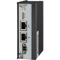
| Product Type | Modbus/TCP Communication Coupler for AMAX-5000 series I/O modules |
| Dimensions | Approximately 100 mm × 70 mm × 60 mm (refer to Figure 2.7) |
| Weight | Approx. 190 g |
| Power Supply | 24 VDC (±20%), dual power input supported |
| Maximum Bus Current | 2 A |
| Protocol | Modbus TCP |
| Transmission Rate | 100 Mbps |
| Number of TCP Connections | 16 |
| Maximum I/O Modules | 256 (excluding AMAX-5079) |
| Group ID Support | 0–255 (maximum 20 groups) |
| Cable Redundancy | Supported via LAN2 (EtherCAT cable redundancy) |
| LED Indicators | PWR, RUN, BUS, OC (over current), OV1/OV2 (over voltage), UV1/UV2 (under voltage) |
| ID Switch | Two rotary switches (x16 and x1) for setting ID (0–255) |
| Connectors | Pluggable 4-pin push-in terminal (power) and 2× RJ45 (LAN1: Modbus TCP, LAN2: Modbus TCP or EtherCAT cable redundancy) |
| Operating Temperature | -25 to 60 °C (vertical mounted) |
| Storage Temperature | -40 to 85 °C |
| Relative Humidity | 95% (non-condensing) |
| Certifications | CE, FCC Class A |
| Maintenance & Cleaning | Disconnect power, clean with a damp cloth; do not use liquid sprays |
| Safety Precautions | Disconnect power before configuration; avoid static electricity; use only in restricted access areas |
| Spare Parts & Reparability | No user-serviceable parts inside; contact qualified service personnel for repairs |
Frequently Asked Questions - AMAX-5070-A Advantech
User questions about AMAX-5070-A Advantech
0 question about this device. Answer the ones you know or ask your own.
Ask a new question about this device
Download the instructions for your Programmable Logic Controller in PDF format for free! Find your manual AMAX-5070-A - Advantech and take your electronic device back in hand. On this page are published all the documents necessary for the use of your device. AMAX-5070-A by Advantech.
USER MANUAL AMAX-5070-A Advantech
natural_image
Line drawing of two ADAM industrial control units on a green background (no text or symbols)AMAX-5070
Modbus/TCP Communication Coupler
Copyright
The documentation and the software included with this product are copyrighted 2024 by Advantech Co., Ltd. All rights are reserved. Advantech Co., Ltd. reserves the right to make improvements in the products described in this manual at any time without notice. No part of this manual may be reproduced, copied, translated or transmitted in any form or by any means without the prior written permission of Advantech Co., Ltd. Information provided in this manual is intended to be accurate and reliable. However, Advantech Co., Ltd. assumes no responsibility for its use, nor for any infringements of the rights of third parties, which may result from its use.
Acknowledgments
Intel and Pentium are trademarks of Intel Corporation.
Microsoft Windows and MS-DOS are registered trademarks of Microsoft Corp.
All other product names or trademarks are properties of their respective owners.
Product Warranty (2 years)
Advantech warrants to you, the original purchaser, that each of its products will be free from defects in materials and workmanship for two years from the date of purchase.
This warranty does not apply to any products which have been repaired or altered by persons other than repair personnel authorized by Advantech, or which have been subject to misuse, abuse, accident or improper installation. Advantech assumes no liability under the terms of this warranty as a consequence of such events.
Because of Advantech's high quality-control standards and rigorous testing, most of our customers never need to use our repair service. If an Advantech product is defective, it will be repaired or replaced at no charge during the warranty period. For out-of-warranty repairs, you will be billed according to the cost of replacement materials, service time and freight. Please consult your dealer for more details.
If you think you have a defective product, follow these steps:
-
Collect all the information about the problem encountered. (For example, CPU speed, Advantech products used, other hardware and software used, etc.) Note anything abnormal and list any onscreen messages you get when the problem occurs.
-
Call your dealer and describe the problem. Please have your manual, product, and any helpful information readily available.
-
If your product is diagnosed as defective, obtain an RMA (return merchandise authorization) number from your dealer. This allows us to process your return more quickly.
-
Carefully pack the defective product, a fully-completed Repair and Replacement Order Card and a photocopy proof of purchase date (such as your sales receipt) in a shippable container. A product returned without proof of the purchase date is not eligible for warranty service.
-
Write the RMA number visibly on the outside of the package and ship it prepaid to your dealer.
Part No. 2003507001 Edition 2
Printed in Taiwan July 2024
Declaration of Conformity
CE
This product has passed the CE test for environmental specifications when shielded cables are used for external wiring. We recommend the use of shielded cables. This kind of cable is available from Advantech. Please contact your local supplier for ordering information.
Test conditions for passing also include the equipment being operated within an industrial enclosure. In order to protect the product from damage caused by electrostatic discharge (ESD) and EMI leakage, we strongly recommend the use of CE-compliant industrial enclosure products.
FCC Class A
This equipment has been tested and found to comply with the limits for a Class A digital device, pursuant to part 15 of the FCC Rules. These limits are designed to provide reasonable protection against harmful interference when the equipment is operated in a commercial environment. This equipment generates, uses, and can radiate radio frequency energy and, if not installed and used in accordance with the instruction manual, may cause harmful interference to radio communications. Operation of this equipment in a residential area is likely to cause harmful interference. In this event, users are required to correct the interference at their own expense.
Technical Support and Assistance
- Visit the Advantech website at www.advantech.com/support to obtain the latest product information.
- Contact your distributor, sales representative, or Advantech's customer service center for technical support if you need additional assistance. Please have the following information ready before you call:
– Product name and serial number
– Description of your peripheral attachments
– Description of your software (operating system, version, application software, etc.)
– A complete description of the problem
– The exact wording of any error messages
Safety Precaution - Static Electricity
Follow these simple precautions to protect yourself from harm and the products from damage.
To avoid electrical shock, always disconnect the power from your PC chassis before you work on it. Don't touch any components on the CPU card or other cards while the PC is on.
■ Disconnect power before making any configuration changes. The sudden rush of power as you connect a jumper or install a card may damage sensitive electronic components.
Safety Instructions
- Install the system only in area with restricted access.
- Read these safety instructions carefully.
- Retain this user manual for future reference.
- Disconnect the equipment from all power outlets before cleaning. Use only a damp cloth for cleaning. Do not use liquid or spray detergents.
-
For pluggable equipment, the power outlet socket must be located near the equipment and easily accessible.
-
Protect the equipment from humidity.
-
Place the equipment on a reliable surface during installation. Dropping or letting the equipment fall may cause damage.
-
The openings on the enclosure are for air convection. Protect the equipment from overheating. Do not cover the openings.
-
Ensure that the voltage of the power source is correct before connecting the equipment to a power outlet.
-
Position the power cord away from high-traffic areas. Do not place anything over the power cord.
-
All cautions and warnings on the equipment should be noted.
-
If the equipment is not used for a long time, disconnect it from the power source to avoid damage from transient overvoltage.
-
Never pour any liquid into an opening. This may cause fire or electrical shock.
-
Never open the equipment. For safety reasons, the equipment should be opened only by qualified service personnel.
-
If any of the following occurs, have the equipment checked by service personnel:
– The power cord or plug is damaged.
– Liquid has penetrated the equipment.
– The equipment has been exposed to moisture.
- The equipment is malfunctioning, or does not operate according to the user manual.
– The equipment has been dropped and damaged.
– The equipment shows obvious signs of breakage.
-
Do not leave the equipment in an environment with a storage temperature of below -20 °C (-4 °F) or above 60 °C (140 °F) as this may damage the components. The equipment should be kept in a controlled environment.
-
CAUTION: Batteries are at risk of exploding if incorrectly replaced. Replace only with the same or equivalent type as recommended by the manufacturer. Discard used batteries according to the manufacturer's instructions.
-
In accordance with IEC 704-1:1982 specifications, the sound pressure level at the operator's position does not exceed 70 dB (A).
DISCLAIMER: These instructions are provided according to IEC 704-1 standards. Advantech disclaims all responsibility for the accuracy of any statements contained herein.
Contents
Chapter 1 Introduction......1
1.1 Introduction ...... 2
1.2 Hardware System Diagram 2
Figure 1.1 AMAX-5070 Hardware System Diagram ...... 2
Figure 1.2 AMAX-5070 Cable Redundancy Hardware System Diagram in Tree Topology .... 3
Figure 1.3 AMAX-5070 Cable Redundancy Hardware System Diagram in Ring Topology .... 4
1.2.1 Power Application and Consumption 5
Figure 1.4 Power Module Application Diagram .... 5
Table 1.1: Coupler and Power Module Rated Voltage and Mac Current....5
Table 1.2: SubDevice Power Consumption....5
1.2.2 Hardware Installation and Information 5
1.2.3 AMAX-5070 Support SubDevices List 5
Chapter 2 AMAX-5070 Modbus/TCP Coupler with ID Switch ....7
2.1 AMAX-5070 Specification 8
Figure 2.1 AMAX-5070 Module 8
2.1.1 General 9
2.1.2 Power Input....9
2.1.3 Modbus/TCP Coupler 9
2.1.4 Environment....9
2.1.5 Reliability Test....9
2.2 Indicator 10
Figure 2.2 AMAX-5070 Module LED Indicator.... 10
Table 2.1: AMAX-5070 Module LED Indicator.... 10
2.3 ID Switch 11
Figure 2.3 AMAX-5070 ID Switch 11
Table 2.2: AMAX-5070 ID Switch 11
2.4 Pin Definition 12
Figure 2.4 AMAX-5070 Module Front View 12
Figure 2.5 AMAX-5070 Module Side View 12
Table 2.3: Upper 4-Pin Connector.... 13
Table 2.4: Lower 2 LAN Port 13
2.5 Application Wiring 13
Figure 2.6 Wiring for AMAX-5070 Power Input.... 13
2.6 Dimensions 14
Figure 2.7 AMAX-5070 Dimensions 14
2.7 AMAX-5070 Object Dictionary 14
Table 2.5: Input Data (4x9901 - 4x9913).... 14
Chapter 3 System Configuration .....17
3.1 Connect and Search Modules.... 18
3.1.1 Searching for the Coupler 18
Figure 3.1 Searching for AMAX-5070.... 18
Figure 3.2 : AMAX-5070 in Different Network.... 19
3.1.2 Searching for the EtherCAT SubDevice 20
Figure 3.3 : The Subdevice Condition and Topology...... 20
Figure 3.4 Group ID Conflict....21
3.2 Module Information 21
Figure 3.5 Coupler Configuration Page 21
Figure 3.6 Different Subnet Mask Error.... 22
Figure 3.7 Re-setting the AMAX-5070 IP Address 23
Figure 3.8 Coupler Configuration in Different Internet Segment 23
3.2.1 Main Node Information page (Coupler) 24
Figure 3.9 Coupler Information Page 24
3.2.2 Subordinate Node Information page (SubDevice) 24
Figure 3.10 SubDevice Information Page.... 24
3.2.3 SubDevice Support List 25
Figure 3.11Support SubDevice List.... 25
3.3 Module Setting 25
3.3.1 Network Configuration 25
Figure 3.12Network Configuration Page 25
3.3.2 AMAX-5070 Switch ID 26
Figure 3.13AMAX-5070 Switch ID.... 26
3.3.3 Rescan the SubDevice and Topology 26
Figure 3.14 Rescan Function 26
Figure 3.15Time out 27
3.3.4 Restart the OS of the AMAX-5070.... 27
Figure 3.16 Restart the System.... 27
3.3.5 Cable Redundancy Configuration.... 28
Figure 3.17 Cable Redundancy Setting.... 28
Figure 3.18 Cable Redundancy Notification for Wiring.... 28
Figure 3.19 Cable Redundancy Notification for Estimated Reset Time 29
3.3.6 Obtaining the Topology Status 29
Figure 3.20 Topology Status 30
3.4 Modbus Address Setting.... 31
Figure 3.21AMAX-5070 Modbus Client Address and Rotary Switch 31
Table 3.1: AMAX-5074 Group ID and Modbus Client Device ID31
Figure 3.22System Topology with Group ID and Device ID ..... 32
Figure 3.23Modbus Address in Different Group ID and User Mode 32
3.4.1 Modbus Addresses for Connected Modules (Fixed Mode).... 33
Figure 3.24Modbus Address Setting Page.... 33
Figure 3.25Modbus Address 33
3.4.2 Export the List of Modbus TCP Addresses for All Modules ..... 34
Figure 3.26Export the ModBus TCP Address in Fixed Mode..... 34
Figure 3.27Modbus TCP Addresses and Modules List in CSV File (Fixed Mode) 34
3.4.3 Modbus Addresses for Connected Modules (Flexible Mode) ..... 35
Figure 3.28Flexible Mode 35
Figure 3.29Modbus Coil Status and Holding Register.... 36
Figure 3.30Flexible Mode Mapping Topology Status ...... 36
Figure 3.31 Check the Unmatched SubDevices.... 37
3.4.4 Export the List of Modbus TCP Addresses for All Modules (Flexible
Mode)....37
Figure 3.32Export the ModBus TCP Address in Flexible Mode . 37
Figure 3.33Modbus TCP Addresses and Modules List in CSV File (Flexible Mode).... 38
3.4.5 Identify the Modules of Abnormal Communication 38
Figure 3.34Mark Communication Status 38
Figure 3.35Mark Communication Status when Module disconnection.... 39
Chapter 4 Coupler & SubDevice Config ...... 41
4.1 Coupler and SubDevice Configuration.... 42
4.1.1 Device Categories.... 42
Figure 4.1 Device Categories 42
Figure 4.2 Coupler or Coordinator Module Information ..... 43
Figure 4.3 SubDevice Information 43
Figure 4.4 Unknown Module Information.... 44
4.1.2 Storing and Loading Configurations.... 44
Figure 4.5 Save and Load Configuration 44
Figure 4.6 DI/DO Configuration 45
Figure 4.7 Example of Not Supported SubDevice UI 45
4.1.3 Locate SubDevices 46
Figure 4.8 Locating SubDevice Function.... 46
Figure 4.9 SubDevice without LED Locate Function 46
4.2 Obtain and Configure Coupler and SubDevice 47
4.2.1 Obtain Power SubDevices Status.... 47
Figure 4.10 Power Status 47
Figure 4.11 Power Status and Modbus Address Information ..... 47
4.2.2 Analogue Input SubDevices.... 48
Figure 4.12Analogue Input Status 48
Figure 4.13 Analogue Input Value and Modbus Address Information.... 49
Figure 4.14 Expand the Tree and Change the AMAX-5018 Range 49
Figure 4.15 Apply the Change for All Channels of This SubDevice 50
4.2.3 Analogue Output SubDevices.... 50
Figure 4.16 Analogue Output Status 50
Figure 4.17 Analogue Output Value and Modbus Address Information....51
Figure 4.18 Expand the Tree and Change the AMAX-5024 Range 51
4.2.4 Digital Input SubDevices.... 52
Figure 4.19Digital Input Status 52
Figure 4.20 Digital Input Value and Modbus Address Information .. 52
Figure 4.21Enable AMAX-5060 Digital Filter 53
4.2.5 Digital Output SubDevices 54
Figure 4.22Digital Output Status.... 54
Figure 4.23 Digital Output Value and Modbus Address Information 54
Figure 4.24Change AMAX-5060 Digital Output Status.... 55
Figure 4.25Configure AMAX-5060 Safety Value 56
Figure 4.26AMAX-5060 Safety Setting.... 56
4.2.6 Counter/Encoder SubDevices.... 57
Figure 4.27Counter and Encoder Status 57
Figure 4.28Counter/Encoder and Modbus Address Information 57
Figure 4.29Change AMAX-5080 CNT Mode 58
Figure 4.30 Enable the Latch Counter.... 59
Chapter 5 Utility Management Tool ......61
5.1 Favorite Group Function 62
Figure 5.1 Add New Favorite Group 62
Figure 5.2 Create New Group.... 62
Figure 5.3 Add New Device for Favorite Group.... 62
Figure 5.4 Configure the Ethernet Device 63
Figure 5.5 New Device Has Been Added Under Newgroup ..... 64
Figure 5.6 Connect Status is GOOD 64
Figure 5.7 Connect Status is CorrespondingFail 65
Figure 5.8 Configure the Modules in Favorite Group .... 65
5.2 Terminal for Command Testing Function.... 66
Figure 5.9 Entire the Terminal for Command Testing ..... 66
Figure 5.10Connect to AMAX-5070 via Terminal for Command Testing....67
Figure 5.11 Modbus Information in Terminal for Command Testing 67
Figure 5.12ASCII command in Terminal for Command Testing. 68
Chapter 1
Introduction
1.1 Introduction
To enhance your experience with the AMAX-5070, please download the manual and software from the Advantech office website:
AMAX-5000 Series I/O Modules User Manual
Advantech I/O Module Utility
This manual focuses on the AMAX-5070 Modbus/TCP Coupler. For more information about the AMAX-5000 series I/O modules, please download the AMAX-5000 Series I/O user manual from our official website.
1.2 Hardware System Diagram
The system hardware architecture for using the AMAX-5070 is shown in Figure 1.1. LAN ports 1 and 2 can connect to the MainDevice (MDevice) via Modbus/TCP, with LAN port 2 providing cable redundancy via EtherCAT. Refer to Figure 1.2 for the cable redundancy system diagram in tree topology and Figure 1.3 for the ring topology.

Figure 1.1 AMAX-5070 Hardware System Diagram

Figure 1.2 AMAX-5070 Cable Redundancy Hardware System Diagram in Tree Topology

Figure 1.3 AMAX-5070 Cable Redundancy Hardware System Diagram in Ring Topology
1.2.1 Power Application and Consumption
The AMAX-5070 provides a maximum of 2A current for the SubDevices. To support additional SubDevices, insert the AMAX-5001 between I/O modules (see Figure 1.4). Refer to Tables 1.1 and 1.2 for power consumption details of power modules and SubDevices. For precise power consumption of each module, refer to the AMAX-5000 Series I/O User Manual.

Figure 1.4 Power Module Application Diagram
| Table 1.1: Coupler and Power Module Rated Voltage and Mac Current | ||
| Module Name Rated Voltage | (VDC) Maximum Current (A) | |
| AMAX-5001 24 (±20%) | 2 | |
| AMAX-5070 24 (±20%) | 2 | |
| AMAX-5074 24 (±20%) | 2 | |
| Table 1.2: SubDevice Power Consumption | |
| Module Name | Power Consumption (W) |
| AMAX-5079 | N/A |
| Other AMAX-5000 Series SubDevices | Approx. 3^[1] |
[1]: For each module's precious power consumption, please refer to the AMAX-5000 Series I/O User Manual.
1.2.2 Hardware Installation and Information
For installation positions, wiring, cable length, cable selection, RJ45 selection, and electromagnetic protection for the AMAX-5070 and AMAX-5000 Series I/O modules, please refer to the AMAX-5000 Series User Manual.
1.2.3 AMAX-5070 Support SubDevices List
For a list of SubDevices supported by the AMAX-5070, download the Advantech I/O Module Utility from the AMAX-5070 website and refer to the Subordinate Node Information page: Subordinate Node Information page (SubDevice).
Chapter 2
AMAX-5070 Modbus/TCP Coupler with ID Switch
2.1 AMAX-5070 Specification
The AMAX-5070 is a coupler for the AMAX-5000 slice I/O system, offering a compact and flexible Modbus/TCP I/O solution. The AMAX-5000 series I/O modules feature several design elements to reduce engineering time for customers, including push-in wiring terminals, front LED diagnostics, slide-in installation on DIN rails, and a bus power monitoring mechanism.

Figure 2.1 AMAX-5070 Module
2.1.1 General
■ Certification: CE, FCC class A
Connector: Pluggable 4P push-in terminal (#24\~16 AWG) and 2x RJ45
■ Module Enclosure: Polycarbonate + Aluminum Alloy
■ Protocol: Modbus TCP
■ Transmission Rate: 100Mbps
■ LED Indicator: PWR, RUN, Power Diagnosis LED
■ Weight: Approx. 190g
2.1.2 Power Input
■ Rated Voltage: 24VDC (±20%)
■ Dual Power Input: Supported
Max Current on Bus: 2A
Diagnosis Function:
- Over/under voltage for input 1&2
– Over current output on bus
2.1.3 Modbus/TCP Coupler
■ Function: Coupling AMAX-5000 EtherCAT IO Module to Modbus/TCP network
■ Cable: Ethernet/EtherCAT cable (min. Cat. 5), shielded
■ Distance between stations: Max. 100 m (100BASE-TX)
■ Interface: 2 x RJ45,
- LAN1: Modbus/TCP,
– LAN2: Modbus/TCP (default) or EtherCAT Cable Redundancy
TCP Connection No.: 16
■ Response Time: 5ms
■ IO Configuration: Advantech I/O Module Utility
■ Maximum IO Modules: 256 (excluding AMAX-5079)
■ Group ID Support: 0\~255 (maximum 20 groups)
2.1.4 Environment
Operation Temperature: -25\~60°C (vertical mounted)
■ Storage Temperature: -40\~85°C
■ Relative Humidity: 95% (non-condensing)
■ Storage Humidity: 95% (non-condensing)
2.1.5 Reliability Test
■ High Temperature Test: IEC 68-2-78
■ Low Temperature Test: IEC 68-2-2
■ Random Vibration Test: IEC 68-2-64
■ Shock Test: IEC 68-2-27
■ Package Drop Test: Federal Standard
2.2 Indicator

Figure 2.2 AMAX-5070 Module LED Indicator
| Table 2.1: AMAX-5070 Module LED Indicator | |||
| LED Color Indication Behavior | |||
| PWR Green ON | Power ON | ||
| RUN Green Blinking Running | |||
| BUS Green ON | Bus Power ON | ||
| OC Red ON Bus | Over Current (2A) | ||
| OV1 Red ON V1 | Over-voltage (28.8V) | ||
| OV2 Red ON V2 | Over-voltage (28.8V) | ||
| UV1 Red ON V1 | Under-voltage (19.2V) | ||
| UV2 Red ON V2 | Under-voltage (19.2V) | ||
2.3 ID Switch

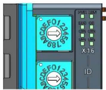
Figure 2.3 AMAX-5070 ID Switch
| Table 2.2: AMAX-5070 ID Switch | ||
| Switch Number (Top to Bottom) Multiple Range (HEX) | ||
| SW2 x16 0 ~ F | ||
| SW1 x1 0 ~ F | ||
| Example (SW2, SW1) = (4, C), then | ID = 4x16 + 12x1 = 76 | |
2.4 Pin Definition

Figure 2.4 AMAX-5070 Module Front View

Figure 2.5 AMAX-5070 Module Side View
| Table 2.3: Upper 4-Pin Connector | |
| Pin Number (Top to Bottom) Pin | Definition |
| 1 V1+ | |
| 2 GND | |
| 3 V2+ | |
| 4 | FG |
| Table 2.4: Lower 2 LAN Port | |
| LAN Number (Top to Bottom) Port Definition | |
| 1 Modbus/TCP signal input | |
| 2 Modbus/TCP signal input or Ether | CAT cable redundancy |
2.5 Application Wiring
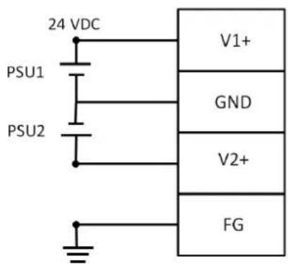
Figure 2.6 Wiring for AMAX-5070 Power Input
2.6 Dimensions
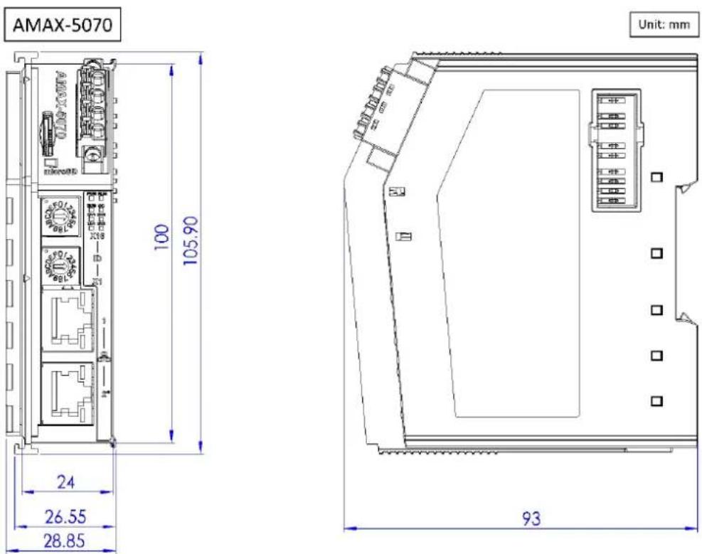
Figure 2.7 AMAX-5070 Dimensions
2.7 AMAX-5070 Object Dictionary
| Table 2.5: Input Data (4x9901 - 4x9913) | |||||
| Index (hex) | Name Meaning Data | type | Flags | Default value | |
| 4x9901 Over | _Voltage_1 Voltage 1 > 28.8V | (24V*1.2) [1] | UINT | RO 0x0000 | |
| 4x9902 Under | _Voltage_1 Voltage 1 < 19.2V | (24V*0.8) [1] | UINT | RO 0x0000 | |
| 4x9903 Over | _Voltage_2 Voltage 2 > 28.8V | (24V*1.2) [1] | UINT | RO 0x0000 | |
| 4x9904 Under | _Voltage_2 Voltage 2 < 19.2V | (24V*0.8) [1] | UINT | RO 0x0000 | |
| 4x9905 Over | _Current Bus current > 2A [1] | UINT RO 0x0000 | |||
| 4x9906 Voltage | Input voltage 1 | UINT RO 0x0000 | |||
| 4x9907 Voltage | Input voltage 2 | UINT RO 0x0000 | |||
| 4x9908 Current | Input current | UINT | RO 0x0000 | ||
| 4x9909 ID Switch | Rotary switch value | UINT | RO 0x0000 | ||
| 4x9910 Module_count | Current SubDevice Quantity (Reserved) | UINT | RO 0x0000 | ||
| 4x9911 | Module_count | Current SubDevice Quantity [2] | UINT | RO 0x0000 | |
| 4x9912 Cable | redundancy_status | Cable redundancy status | UINT | RO 0x0000 | |
| 4x9913 Cable | redundancy_linking Cable | redundancy linking status | UINT | RO 0x0000 | |
[1]: The formula to calculate the real voltage or current is as follows: Real Voltage/Current = (Measured voltage / 1000). For example, if the measured voltage is 24168, the real voltage would be 24.168 V.
[2]: This value won't count the AMAX-5070 and AMAX-5079.
Chapter 3
System Configuration
3.1 Connect and Search Modules
3.1.1 Searching for the Coupler
Right click Ethernet and select the Search Device (Figure 3.1). The default node name is AMAX-5070, which is the main node of the device.
![Advantech ADAM/APAX Utility (Win32) Ver File Tools Setup Help Serial COM1 COM2 COM3 Ethernet 192.168.56.1 192.168.196.1 172.16.12.64 172.16.12.33-[AIMB-787_ADAM] 172.16.12.80-[AMAX-5070_Chilis] 172.16.12.149-[ADAM-6251_00D0C9FEBFB* 172.16.12.179-[ADAM-6050-Nick] 172.16.12.234-[AIMB-787_ADAM] 172.16.12.250-[WISE-4210-AP] 172.16.13.2-[AMAX-5070-hark] 172.16.13.227-[WISE-2834] 172.16.13.228-[WISE-2834] Others 10.0.0.2-[AIMB-787_ADAM] Favorite Group ADAM4500_5510Series Wireless Sensor Networks](/content/2026/05/910341/images/1ae66739eee7e321578ebfa1822dcadd712667626da9645f15a43a4cb8f18d33.jpg)
Figure 3.1 Searching for AMAX-5070
If the Coupler (e.g. AMAX-5070, AMAX-5074) is under a different network segment, it will be displayed under the Others node (Figure 3.2).
![Advantech ADAM/APAX Utility (Win32) Version 2.6.00 (B16 2022/12/22) File Tools Setup Help Serial COM1 COM2 COM3 Ethernet 192.168.56.1 192.168.196.1 172.16.12.64 172.16.12.149-[ADAM-6251_000] 172.16.12.179-[ADAM-6050_Nic1] 172.16.12.234-[AIMD-707_ADAH] 172.16.13.2-[AMAX-5070_henk] 172.16.13.227-[WISE-2834] 172.16.13.228-[WISE-2834] Others 100.0.199-[AMAX-5070_Chile] Favorite Group ADAM4500_5510Series Wireless Sensor Networks Setting Network MAC Address 74-FE-48-6E-88-61 IP Address 10.0.0.199 Subnet Mask 255.255.254.0 Default Gateway 0.0.0.0 Apply Static ○ DHCP ANAX-5070 Switch ID: Unknown Device Topology Rescan Apply System Restart Apply Cable-Redundancy Setting Current Status: Unknown Cable Link Status: Unknown Setting: ○ Enable ○ Disable Apply Topology Status Total Slave Count: Unknown Ring0 Slave Count: Unknown Scan Busy: Unknown Ring1 Slave Count: Unknown Refresh](/content/2026/05/910341/images/0bdd29397d78b169792d6c39f8b5a260cff1579d9efb2969e2da913f215798a3.jpg)
Figure 3.2 : AMAX-5070 in Different Network
3.1.2 Searching for the EtherCAT SubDevice
Clicking on the Coupler will display the current conditions and topology of the SubDevices. In the first layer, you will find the AMAX-5070 and AMAX-5074 device. In the second layer, you will find SubDevices such as AMAX-5024 and AMAX-5051. These SubDevices are positioned under either AMAX-5074 or AMAX-5070 (as shown in Figure 3.3). This hierarchical arrangement allows for a clear representation of the connectivity and placement of the SubDevices within the system.
The label "G0" after the Coupler name signifies Group 0. This number, representing the Group ID, will be automatically synchronized according to the rotary switch on the Coupler. For instance, if the rotary switch on an AMAX-5074 Coupler is set to (x16, x1)=(A,1), the Group ID will be set to G161.
However, in the case of AMAX-5070, the Group ID is always set to G0 (Group ID 0) and is not affected by the rotary switch on the Coupler. The Group ID for AMAX-5070 remains fixed and does not change based on the rotary switch position.
The label "S0" after the SubDevice name indicates that it is the first module connected in the whole system. In Figure 3.3, the first module is AMAX-5056, which has been assigned the label S0. The second module, which is an AMAX-5018, has been assigned the label S1. The third module, AMAX-5018, has been assigned the label S2.
If a module is not currently supported or recognized, it will be marked as Unknown. This typically occurs when the module is not compatible with the system or when its information is not available or updated in the current configuration.
![Serial COM1 COM2 COM3 Ethernet 192.168.56.1 192.168.196.1 172.16.12.64 172.16.12.35-[WISE-6610-US] 172.16.12.47-[AMAX-5070 chih] AMAX-5070 Coupler(G0) AMAX-5056(S0) AMAX-5018(S1) AMAX-5018(S2) AMAX-5074(G15)(S3) AMAX-5018(S4) AMAX-5074(G14)(S5) AMAX-5080(S6) 172.16.12.96-[ADAM-6060] 172.16.12.105-[WISE-6610-Stank 172.16.12.107-[ADAM-6060] 172.16.12.108-[ICR-323x] 172.16.12.120-[WISE-6610-AS] 172.16.12.130-[AMAX-5070-HRI 172.16.12.158-[ADAM-6717] 172.16.12.248-[ADAM-6717] 172.16.13.18-[ADAM-6750] 172.16.13.227-[WISE-2834] 172.16.13.228-[WISE-2834] Others Favorite Group ADAM4500_5510Series Wireless Sensor Networks](/content/2026/05/910341/images/d7befc6f31570f839976ad35591c5336fa08ef4eeb35d7daf62b848209c8d223.jpg)
Figure 3.3 : The Subdevice Condition and Topology
The node will display an red exclamation mark "!" when there is a conflict with the Group ID.
![Ethernet 192.168.56.1 192.168.196.1 172.16.12.64 172.16.12.35-[WISE-6610-US] 172.16.12.47-[AMAX-5070 chik] AMAX-5070 Coupler(G0) AMAX-5056(S0) Unknown(S1) AMAX-5018(S2) AMAX-5018(S3) AMAX-5080(S4) AMAX-5074(G51)(S5) AMAX-5018(S6) AMAX-5074(G0)(S7) AMAX-5018(S8) 172.16.12.49-[ADAM-6717]](/content/2026/05/910341/images/e1b657a00fb39d7f0b4768a64de091a94b9e82a26bc18242b6c29aa483833caa.jpg)
Figure 3.4 Group ID Conflict
3.2 Module Information
Clicking on the main node will display the information and configuration (Figure 3.5). If the following error message pops up, it indicates that the utility has recognized the same network segment but the command cannot reach the module due to subnet mask settings (Figure 3.6).
![Advantech ADAM/APAX Utility (Win32) Version 2.6.00 (B16 2022/12/22) File Tools Setup Help Serial COM1 COM2 COM3 Ethernet 192.168.56.1 192.168.196.1 172.16.12.64 172.16.12.33-[AIMB-787_ADAM 172.16.12.80-[AMAX-5070_Chili AMAX-5070 Coupler(SU) AMAX-5056SO(SO) Unknown(S1) AMAX-5018(S2) AMAX-5018(S3) AMAX-5056SO(S4) AMAX-5018(S5) AMAX-5018(S6) AMAX-5018(S7) 172.16.12.149-[ADAM-6251_00] 172.16.12.179-[ADAM-6050-Nic] 172.16.12.234-[AIMB-787_ADA] 172.16.13.2-[AMAX-5070-hark] 172.16.13.227-[WISE-2834] 172.16.13.228-[WISE-2834] Others Favorite Group ADAM4500_5510Series Wireless Sensor Networks Information Setting Modbus Address Setting Communication Diagnosis AMAX-5070 Firmware Firmware Version v1.1.8_70.0.007 Device Name AMAX-5070_Chili Description Modbus/TCP coupler module for AMAX-5000 Apply Description Support Modules Switch ID Module Description 0 AMAX-5056SO AMAX-5056SO 8 DO Module. 1 Unknown Unknown 2 AMAX-5018 AMAX-5018T 6-ch Thermocouple Input Module 3 AMAX-5018 AMAX-5018T 6-ch Thermocouple Input Module 4 AMAX-5056SO AMAX-5056SO 8 DO Module. 5 AMAX-5018 AMAX-5018T 6-ch Thermocouple Input Module 6 AMAX-5018 AMAX-5018 6-ch Thermocouple Input Module 7 AMAX-5018 AMAX-5018T 6-ch Thermocouple Input Module](/content/2026/05/910341/images/53989fe4baa5a66d3ea2ccdb976b20254e9646b1b401ccca7c587e64e6afdb4a.jpg)
Figure 3.5 Coupler Configuration Page
![Serial COM1 COM2 COM3 Ethernet 192.168.56.1 192.168.196.1 172.16.12.64 172.16.12.87-[ADAM-6050_00D0C9FEC050] 172.16.12.96-[ADAM-6251_00D0C9FB6251] 172.16.12.105-[WISE-6610-Stanley] 172.16.12.108-[ICR-323x] 172.16.12.120-[WISE-6610-AS] 172.16.12.130-[AMAX-5070-HRK] 172.16.13.18-[ADAM-6750] 172.16.13.227-[WISE-2834] 172.16.13.228-[WISE-2834] 10.2.3.200 10.0.0.1-[AIMB-787_ADAM] 10.0.0.3-[AMAX-5070_chili] Others Favorite Group ADAM4500_5510Series Wireless Sensor Networks Error Unable to get topology status of the device. Please check the network setting. 確定](/content/2026/05/910341/images/4e3ee430b6e229e64c096f5e6dce1dfc0b9e5a5b2b9d3d78cf2a408b48778d9f.jpg)
Figure 3.6 Different Subnet Mask Error
E.g.
If the Host IP is 10.2.3.200 with a subnet mask of 255.255.255.0, and the AMAX-5070's IP is 10.0.0.3 with a subnet mask of 255.0.0.0.
Both IP addresses have the first octet as 10, which leads the Utility to identify them as the same network segment.
However, due to the subnet mask configuration, the host and AMAX-5070 belong to different network segments (the host's network portion is 10.2.3.0, and AMAX-5070's network portion is 10.0.0.0), resulting in communication failure.
At this point, a page will appear allowing the user to reconfigure the IP address of AMAX-5070.(Figure 3.7)
If you do not want to change the IP addresses of both the Host and AMAX-5070, another approach is to modify the subnet mask of both devices to 255.0.0.0. By doing so, both devices will be within the same network (10.0.0.0), enabling proper communication between them.
![Serial COM1 COM2 COM3 Ethernet 192.168.56.1 192.168.196.1 172.15.12.64 172.15.12.87-[ADAM-6050_00DOC9FE 172.15.12.95-[ADAM-6251_00DOC9FE 172.15.12.105-[WISE-6610-Stunley] 172.15.12.108-[ICR-323x] 172.15.12.120-[WISE-6010-A3] 172.15.12.130-[AMAX-5070-ERK] 172.15.12.248-[ADAM-6750] 172.15.13.18-[ADAM-6750] 172.15.13.227-[WISE-2834] 172.15.13.226-[WISE-2834] 10.2.3.200 10.0.0.1-[AIMB-787_ADAM] 10.0.0.2-[AMAX-5070_chal] Others Favorite Group ADAM4500_5510Series Wireless Sensor Networks Setting Network MAC Address 74-FE-48-6E-B8-61 P Address 10.0.0.3 Subnet Mask 255.0 0.0 Default Gateway 0.0.0.0 Apply Static ○ DHCP AMAX-5070 Switch ID: Unknown System Restart Apply Cable-Redundancy Setting Current Status: Unknown Cable Link Status: Unknown Refresh Setting: ○ Enable ○ Disable Apply Topology Status Total SubDevice Count: Unknown Ring0 SubDevice Count: Unknown Scan Busy: Unknown Ring1 SubDevice Count: Unknown Refresh](/content/2026/05/910341/images/2e38ef83cda7c2f77c6473ec661421dac34f2484789711549c9e489d35a080a6.jpg)
Figure 3.7 Re-setting the AMAX-5070 IP Address
For different networks, the AMAX-5070 Coupler will display the Setting page if the module was in the different Internet segment.
In this condition, the user only can adjust the Internet configurations (e.g. IP address), the other option would be display Unknown, meaning it can't be adjusted. (Figure 3.8)
![Advantech ADAM/APAX Utility (Win32) Version 2.6.00 (B16 2022/12/22) File Tools Setup Help Serial COM1 COM2 COM3 Ethernet 192.168.56.1 192.168.196.1 172.16.12.64 172.16.12.149-[ADAM-6251_00] 172.16.12.179-[ADAM-6050-Nic] 172.16.12.234-[AIMB-787_ADAH 172.16.13.2-[AMAX-5070-herk] 172.16.13.227-[WISE-2834] 172.16.13.228-[WISE-2834] Others 10.0.0.199-[AMAX-5070_Cali Favorite Group ADAM4500_5510Series Wireless Sensor Networks Setting Network MAC Address 74-FE-48-6E-B8-61 IP Address 10.0.0.199 Subnet Mask 255.255.254.0 Default Gateway 0.0.0.0 Apply Static DHCP AMAX-5070 Switch ID: Unknown Device Topology Rescan Apply System Restart Apply Cable-Redundancy Setting Current Status: Unknown Cable Link Status: Unknown Refresh Setting: Enable Disable Apply Topology Status Total Slave Count: Unknown Ring0 Slave Count: Unknown Scan Busy: Unknown Ring1 Slave Count: Unknown Refresh](/content/2026/05/910341/images/7a72c32f98b1d58ec1c73f265ed5f8bad73ff684833bd354711fd4164050cdb0.jpg)
Figure 3.8 Coupler Configuration in Different Internet Segment
3.2.1 Main Node Information page (Coupler)
In the page Information will display Firmware Version and user can modify the Device Name and Description. (Figure 3.9)

Figure 3.9 Coupler Information Page
3.2.2 Subordinate Node Information page (SubDevice)
The SubDevice node of Information will display Module, Current Connected Module and Description. (Figure 3.10)
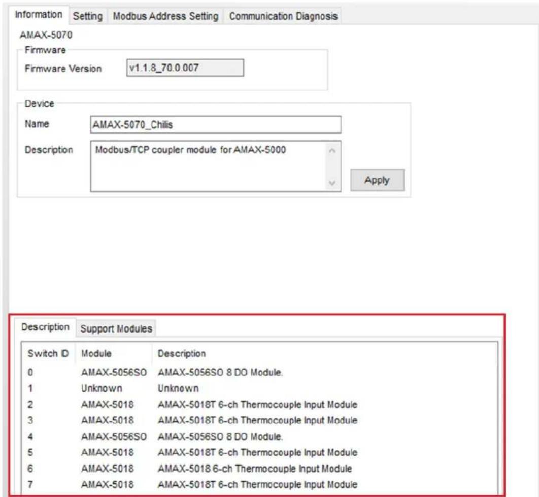
Figure 3.10 SubDevice Information Page
3.2.3 SubDevice Support List
Click the Support Modules tab and check the supported SubDevices list (Figure 3.11).
| Description Support Modules | |
| Support Modules | Description |
| AMAX-5074 | AMAX-5074 EtherCAT Coupler w/ ID Switch |
| AMAX-5001 | AMAX-5001 Power Input w/ 4-ch DI Module |
| AMAX-5051 | AMAX-5051 8-ch Digital Input Module |
| AMAX-5052 | AMAX-5052 16-ch Digital Input Module |
| AMAX-5056 | AMAX-5056 8-ch Sink Type Digital Output Module |
| AMAX-5056SO | AMAX-5056SO 8-ch Source Type Digital Output Module |
| AMAX-5057 | AMAX-5057 16-ch Sink Type Digital Output Module |
| AMAX-5057SO | AMAX-5057SO 16-ch Source Type Digital Output Module |
| AMAX-5015 | AMAX-5015 4-ch RTD Input Module |
| AMAX-5017V | AMAX-5017V 6-ch Voltage Input Module |
| AMAX-5017C | AMAX-5017C 6-ch Current Input Module |
| AMAX-5017H | AMAX-5017H 4-ch High Speed Analog Input Module |
| AMAX-5018 | AMAX-5018 6-ch Thermocouple Input Module |
| AMAX-5024 | AMAX-5024 4-ch Analog Output Module |
| AMAX-5080 | AMAX-5080 2-ch 24V HTL Encoder/Counter Module |
| AMAX-5060 | AMAX-5060 4-ch Relay w/ 2-ch DI Module |
Figure 3.11 Support SubDevice List
3.3 Module Setting
3.3.1 Network Configuration
DHCP and Static Mode can be selected dependence on different applications. DHCP will be assigned internet configuration from DHCP server; In Static Mode user can modify IP address, Subnet Mask and Default Gateway. (Figure 3.12)

Figure 3.12 Network Configuration Page
3.3.2 AMAX-5070 Switch ID
AMAX-5070 rotary switch state would be displayed in the Setting page (Figure 3.13). For more information about switch ID function please check the blue information icon nearby the switch ID number.

Figure 3.13 AMAX-5070 Switch ID
3.3.3 Rescan the SubDevice and Topology
The user can rescan the SubDevice and Topology in Device Topology Rescan then click the Apply button. (Figure 3.14)

Figure 3.14 Rescan Function
If the AMAX-5070 connects to more than 255 SubDevices or the topology has changed during the scan progress, the utility will display an error (Figure 3.15).
![Advantech ADAM/APAX Utility (Win32) Version 2.6.00 (817 2023/03/06) File Tools Settings Help Basic COM1 COM2 COM3 Dialofo 20.1.1.00 195 168 56.1 195 168 106.1 19.8.0.6 172 10.12.04 172 16.12.34 [DBC75B-5-5-BY] 172 16.12.35 [WDS-463-N-W] 172 16.12.39 [XCR-SN] 172 16.12.62 [WDS-463A-MT] 172 16.12.73 [ADAM-4251_DND] 172 16.12.73 [ADAM-3070_ted] 172 16.12.92 [ADAM-3070_CMA] ANAX-5070 Composite(5G) ANAX-5070(SD) Disservio(FI) ANAX-501(MD) ANAX-501(MD) ANAX-501(MD) ANAX-501(MD) ANAX-501(MD) ANAX-501(MD) ANAX-501(MD) ANAX-501(MD) ANAX-501(MD) ANAX-501(MD) ANAX-501(MD) ANAX-501(MD)# ANAX-501(MD) ANAX-501(MD) ANAX-501(MD) ANAX-501(MD) ANAX-501(MD) ANAX-501(MD) ANAX-501(MD) ANAX-501(MD) ANAX-501(MD) ANAX-501(MD) ANAX-501(MD) Anax Anax Group ADAM4320_558M Series Window Series Network Information Setting Modbus Address Setting Communication Diagrams Network MAC Address F47E-48-49 89:81 IP Address 172 16.12.30 Submit User 235 238 239.0 Default Security 172 16.12.34 Device Topology Reason Apply System Reset Apply Case Reduction Setting Current Status Enabled Case Link Status Interest Setting Create Enable Topology Status Total SubDevice Count: Ring/ SubDevice Count: Scan Busy: Ring/ SubDevice Count: Refresh Error Device rescan is Srinout! 确定](/content/2026/05/910341/images/2dd8d7c178b60376fd834c59e9027564bc747c18941f9a2c98bb8e980abc660d.jpg)
Figure 3.15 Time out
3.3.4 Restart the OS of the AMAX-5070
After clicking the Apply button, AMAX-5070 will reboot the system (Figure 3.16).
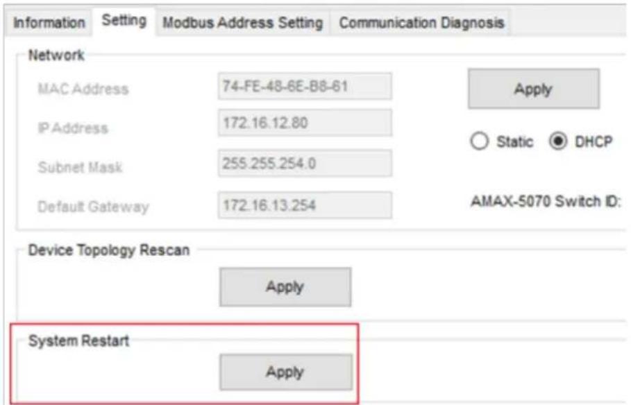
Figure 3.16 Restart the System
3.3.5 Cable Redundancy Configuration
The current status can be observed through Current Status and Cable Link Status, these two fields are not automatically updated, you need to click the Refresh button for acquiring the latest status.
User can select the Enable/Disable button to select cable redundancy and click the Apply to save the setting (Figure 3.17).

Figure 3.17 Cable Redundancy Setting
When set to Enable, a notification pops up to remind the user to confirm the wiring (Figure 3.18).

Figure 3.18 Cable Redundancy Notification for Wiring
It informs the user of the upper time limit that may be consumed (Figure 3.19).

Figure 3.19 Cable Redundancy Notification for Estimated Reset Time
When Cable-Redundancy has been modified to Disable, the notification will remind users to remove the LAN 2 wiring.
3.3.6 Obtaining the Topology Status
This contains several bits of information (Figure 3.20):
- Total SubDevice Count: The total number of SubDevices
- Ring0 SubDevice Count: The number of SubDevices detected through Ethernet port1
- Ring1 SubDevice Count: The number of SubDevices detected through Ethernet port2 (is only enabled in cable-redundancy if it has been set to "Enable", otherwise the value would be set to 0.
- Scan Busy: 0 for non-busy, 1 for busy (If Scan Busy value =1, AMAX-5070 internal system is working with each SubDevice for re-establishes the topology. At this time the SDO command doesn't work, only the PDO data can operate).
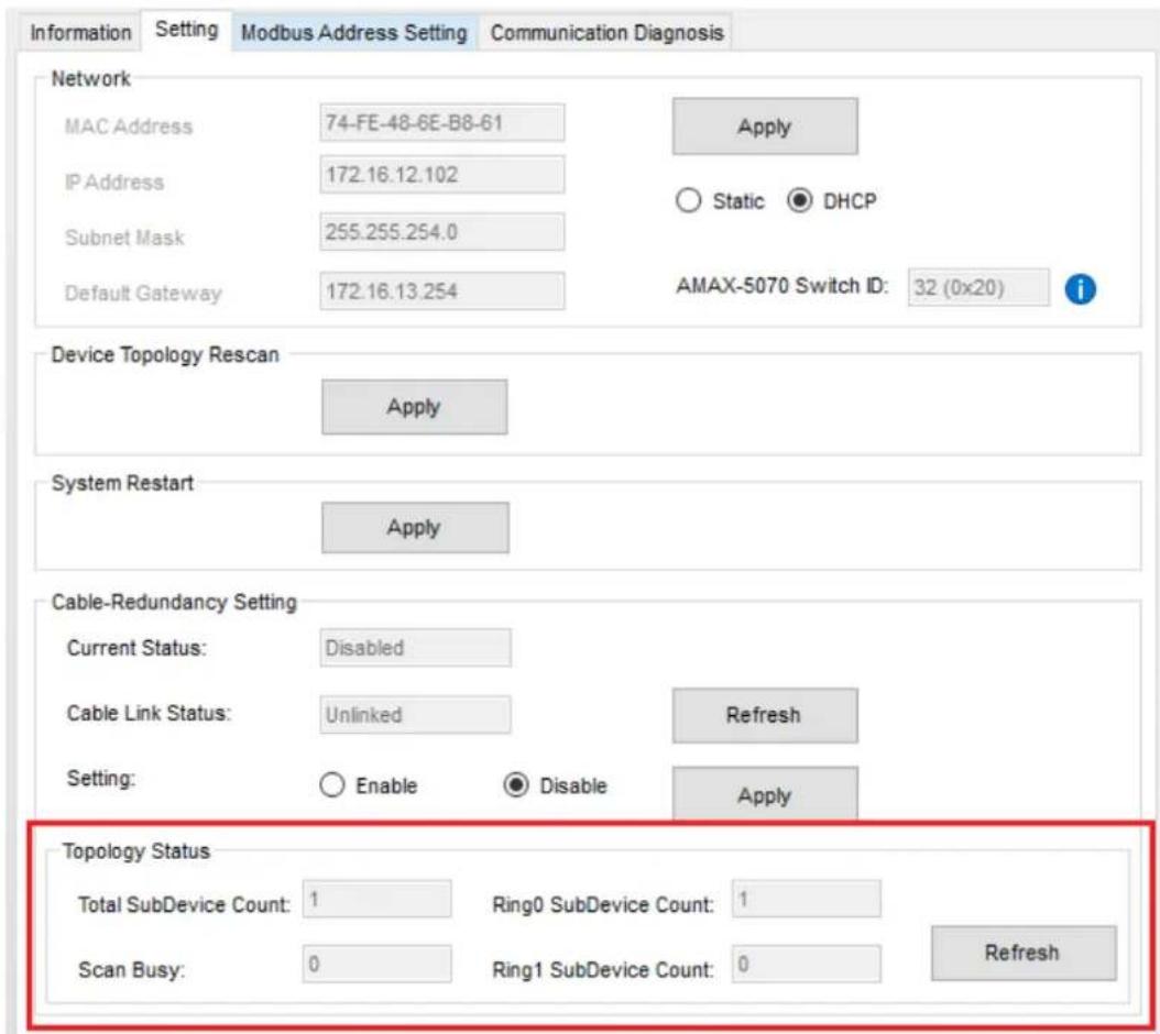
Figure 3.20 Topology Status
3.4 Modbus Address Setting
To adjust the Fixed Mode or Flexible Mode and obtain the corresponding Modbus addresses, click on Modbus Mapping.
For the AMAX-5070 device, the Modbus client address should always be set to Group 0 (G0), and it is not affected by the rotary switch on the device (as shown in Figure 3.21). But the rotary switch value will show on MainDevice.
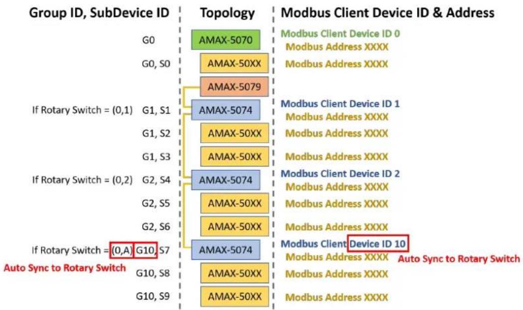
However, for the AMAX-5074 device, both the Advantech Utility Group ID and Modbus client Device ID will automatically synchronize with the value set on the rotary switch (as indicated in Table 3.1). It's important to note that the AMAX-5079 device does not occupy a Modbus address (as depicted in Figure 3.22).
MAC: Sticker on AMAX-5070
Default IP: 10.0.0.10 (LAN 1), 11.0.0.10 (LAN 2)
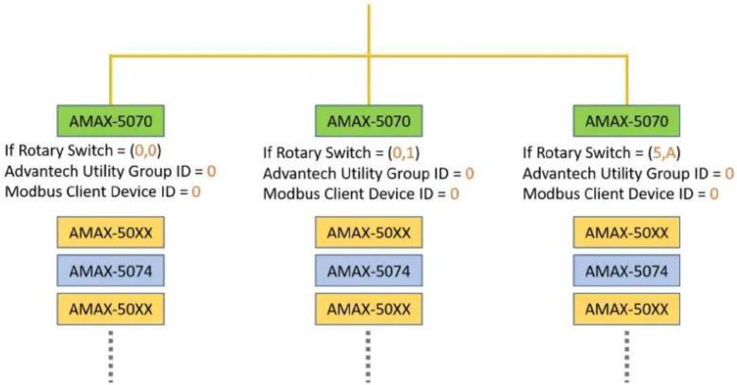
flowchart
graph TD
    A["AMAX-5070\nIf Rotary Switch = (0,0)\nAdvantech Utility Group ID = 0\nModbus Client Device ID = 0"] --> B["AMAX-5070\nAMAX-50XX\nAMAX-5074"]
    A --> C["AMAX-5070\nIf Rotary Switch = (0,1)\nAdvantech Utility Group ID = 0\nModbus Client Device ID = 0"]
    A --> D["AMAX-5070\nAMAX-50XX\nAMAX-5074"]
    A --> E["AMAX-5070\nIf Rotary Switch = (5,A)\nAdvantech Utility Group ID = 0\nModbus Client Device ID = 0"]
Figure 3.21 AMAX-5070 Modbus Client Address and Rotary Switch
Table 3.1: AMAX-5074 Group ID and Modbus Client Device ID
| AMAX-5074 Rotary Switch [1] Advantech Utility Group ID Modbus Client Device ID | ||
| (0, 0) 0 | 0 | |
| (0, 1) 1 | 1 | |
| (0, A) | 10 | 10 |
| (4, C) | 76 | 76 |
[1]: (SW2, SW1) = (0, A), then ID = 0x16 + 10x1 = 10
bar_stacked
| Group ID, SubDevice ID | AMAX-5070 | AMAX-50XX | AMAX-5079 | | ---------------------- | --------- | --------- | --------- | | G0 | | | | | G0, S0 | | | | | G1, S1 | | | | | G1, S2 | | | | | G1, S3 | | | | | G2, S4 | | | | | G2, S5 | | | | | G2, S6 | | | | | G10, S7 | | | | | G10, S8 | | | | | G10, S9 | | | |Figure 3.22 System Topology with Group ID and Device ID
Modbus address will change depending on which mode (Fixed Mode or Flexible Mode) or which Group ID are currently used (Figure 3.23).

other
| Modbus Address | Group ID 0 | Modbus Address | Group ID 1 to 255 | |---|---|---|---| | 0000 | SubDevices | 0000 | SubDevices | | 4900 | | | Flexible Mode | | 4901 | AMAX-5070 Reserved | 5000 | Flexible Mode | | 5000 | | | Flexible Mode | | 5001 | SubDevices | 5001 | Fixed Mode | | 9900 | | | Fixed Mode | | 9901 | AMAX-5070 Reserved | 10000 | Fixed Mode | | 10000 | | | Fixed Mode |Figure 3.23 Modbus Address in Different Group ID and User Mode
3.4.1 Modbus Addresses for Connected Modules (Fixed Mode)
Click on Fixed Mode to obtain the current Modbus Address and Topology (Figure 3.24).

Figure 3.24 Modbus Address Setting Page
Modbus address will be reserved but won't display in the Advantech Utility because the unknown device occupies an address (Figure 3.25).
![Ethernet 192.168.56.1 192.168.196.1 172.16.12.64 172.16.12.35-[WISE-6610-US] 172.16.12.47-[AMAX-5070_chuk] AMAX-5070 Coupler(G0) AMAX-5056(S0) Unknown(S1) AMAX-5018(S2) AMAX-5018(S3) AMAX-5018(S4) AMAX-5080(S5) AMAX-5074(G51)(G6) AMAX-5018(S7) 172.16.12.61-[AMAT-6266_00DC] 172.16.12.96-[ADAM-6050_00DC] 172.16.12.98-[ADAM-6251_00DC] 172.16.12.130-[AMAX-5070-hark]](/content/2026/05/910341/images/591e16c7b16ab09b4aca49dc5928361df716437be665ae2f7ffcb697c0a6a4ce.jpg)
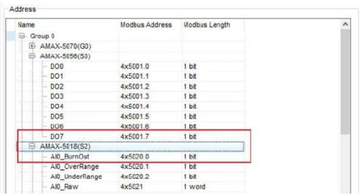
Figure 3.25 Modbus Address
3.4.2 Export the List of Modbus TCP Addresses for All Modules
Press the Export button to export the list with CSV file (Figure 3.26).

Figure 3.26 Export the ModBus TCP Address in Fixed Mode
The CSV file will be downloaded (Figure 3.27).
| A | B | C | D | E | |
| 1 | StartAddress | AddressLength | DataType | ModuleName | AddressName |
| 2 | 4x9901 | 1 word | UINT | AMAX-5070(G0) | Over_Voltage_1 |
| 3 | 4x9902 | 1 word | UINT | AMAX-5070(G0) | Under_Voltage_1 |
| 4 | 4x9903 | 1 word | UINT | AMAX-5070(G0) | Over_Voltage_2 |
| 5 | 4x9904 | 1 word | UINT | AMAX-5070(G0) | Under_Voltage_2 |
| 6 | 4x9905 | 1 word | UINT | AMAX-5070(G0) | Over_Current |
| 7 | 4x9906 | 1 word | UINT | AMAX-5070(G0) | Voltage_1 |
| 8 | 4x9907 | 1 word | UINT | AMAX-5070(G0) | Voltage_2 |
| 9 | 4x9908 | 1 word | DINT | AMAX-5070(G0) | Current |
| 10 | 4x9909 | 1 word | UINT | AMAX-5070(G0) | ID_Switch |
| 11 | 4x9910 | 2 word | UINT | AMAX-5070(G0) | Current_SubDevice_Count |
| 12 | 4x5001.0 | 1 bit | BOOL | AMAX-5060(S0) | DI0 |
| 13 | 4x5001.1 | 1 bit | BOOL | AMAX-5060(S0) | DI1 |
| 14 | 4x5002.0 | 1 bit | BOOL | AMAX-5060(S0) | DO0 |
| 15 | 4x5002.1 | 1 bit | BOOL | AMAX-5060(S0) | DO1 |
| 16 | 4x5002.2 | 1 bit | BOOL | AMAX-5060(S0) | DO2 |
| 17 | 4x5002.3 | 1 bit | BOOL | AMAX-5060(S0) | DO3 |
| 18 | 4x5003.0 | 1 bit | BOOL | AMAX-5056(S1) | DO0 |
| 19 | 4x5003.1 | 1 bit | BOOL | AMAX-5056(S1) | DO1 |
| 20 | 4x5003.2 | 1 bit | BOOL | AMAX-5056(S1) | DO2 |
| 21 | 4x5003.3 | 1 bit | BOOL | AMAX-5056(S1) | DO3 |
| 22 | 4x5003.4 | 1 bit | BOOL | AMAX-5056(S1) | DO4 |
| 23 | 4x5003.5 | 1 bit | BOOL | AMAX-5056(S1) | DO5 |
| 24 | 4x5003.6 | 1 bit | BOOL | AMAX-5056(S1) | DO6 |
| 25 | 4x5003.7 | 1 bit | BOOL | AMAX-5056(S1) | DO7 |
Figure 3.27 Modbus TCP Addresses and Modules List in CSV File (Fixed Mode)
3.4.3 Modbus Addresses for Connected Modules (Flexible Mode)
The Flexible Mode will merge the Subdevices based on the functions and features. The catalog will be hidden if it doesn't have any modules.
DO Control AO Control Counter Control DI Status AO Status AI Status Counter Status System Status
Modbus address will display in Flexible Mode, click the Flexible Mode tab in the Modbus Address Setting (Figure 3.28).
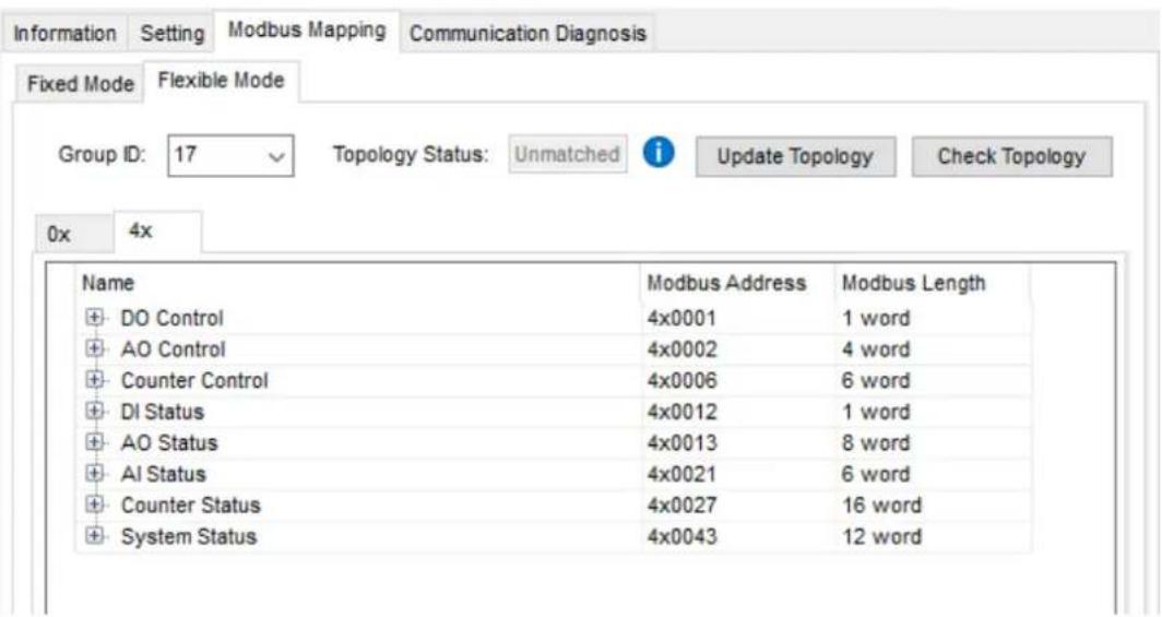
Figure 3.28 Flexible Mode
Flexible mode is used by Group ID to manage the SubDevices. Change the Group ID number to modify the SubDevice configurations in this group. The Coil Status will be displayed in 0x tab (data size is bit, e.g. DI value, burnout status) and the Holding Register in 4x tab (data size is word) (Figure 3.29).

Figure 3.29 Modbus Coil Status and Holding Register
The Topology Status indicates whether the system is in flexible mode and if the Modbus address mapping is functioning correctly. Initially, the status is "Unmatched" which means that the AMAX-5070 device was not mapping the Modbus address. To save the current mapping and topology, click on the "Update" button.
After the update, the Topology Status will display either "Matched" if the current topology matches the saved one, or "Unmatched" if the current topology is different from the saved one (Figure 3.30).
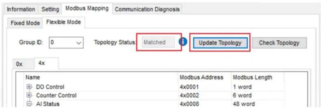
Figure 3.30 Flexible Mode Mapping Topology Status
After saving the current topology, click on "Check topology" to load the saved topology. If the current topology doesn't match the saved one, the system will mark the unmatched SubDevices in red (Figure 3.31).
After clicking on "Update Topology", the saved topology can be updated with any changes made to the current configuration. This allows you to save the latest changes to the topology.
On the other hand, clicking on "Clear Config file" will clear the saved configuration file, effectively removing the saved topology. This action will reset the configuration to its initial state before any changes were made.

Figure 3.31 Check the Unmatched SubDevices
3.4.4 Export the List of Modbus TCP Addresses for All Modules (Flexible Mode)
Press the Export button to export the list with CSV file (Figure 3.32).

Figure 3.32 Export the ModBus TCP Address in Flexible Mode
The CSV file will be downloaded (Figure 10).
| A | B | C | D | E | F | |
| 1 | StartAddress | AddressLength | DataType | Catalog | Function | Device Description |
| 2 | 0x0001 | 1 bit | BOCL | DO Control | Value | AMAX-5056(S0)_CH0 |
| 3 | 0x0002 | 1 bit | BOCL | DO Control | Value | AMAX-5056(S0)_CH1 |
| 4 | 0x0003 | 1 bit | BOCL | DO Control | Value | AMAX-5056(S0)_CH2 |
| 5 | 0x0004 | 1 bit | BOCL | DO Control | Value | AMAX-5056(S0)_CH3 |
| 6 | 0x0005 | 1 bit | BOCL | DO Control | Value | AMAX-5056(S0)_CH4 |
| 7 | 0x0006 | 1 bit | BOCL | DO Control | Value | AMAX-5056(S0)_CH5 |
| 8 | 0x0007 | 1 bit | BOCL | DO Control | Value | AMAX-5056(S0)_CH6 |
| 9 | 0x0008 | 1 bit | BOCL | DO Control | Value | AMAX-5056(S0)_CH7 |
| 10 | 0x0009 | 1 bit | BOCL | Counter Control | Counter config | AMAX-5080(S4)_CHO_Set_Counter |
| 11 | 0x0010 | 1 bit | BOCL | Counter Control | Counter config | AMAX-5080(S4)_CHO_Enable_Latch_Z |
| 12 | 0x0011 | 1 bit | BOCL | Counter Control | Counter config | AMAX-5080(S4)_CHO_Enable_Latch_External |
| 13 | 0x0017 | 1 bit | BOCL | Counter Control | Counter config | AMAX-5080(S4)_CH1_Set_Counter |
| 14 | 0x0018 | 1 bit | BOCL | Counter Control | Counter config | AMAX-5080(S4)_CH1_Enable_Latch_Z |
| 15 | 0x0019 | 1 bit | BOCL | Counter Control | Counter config | AMAX-5080(S4)_CH1_Enable_Latch_External |
| 16 | 0x0025 | 1 bit | BOCL | AI Status | BurnOut | AMAX-5018(S1)_CHO_BurnOut |
| 17 | 0x0026 | 1 bit | BOCL | AI Status | BurnOut | AMAX-5018(S1)_CHO_OverRange |
| 18 | 0x0027 | 1 bit | BOCL | AI Status | BurnOut | AMAX-5018(S1)_CHO_UnderRange |
Figure 3.33 Modbus TCP Addresses and Modules List in CSV File (Flexible Mode)
3.4.5 Identify the Modules of Abnormal Communication
The modules can be highlighted if they communicate abnormally, click the Mark Communication Status under Communication Diagnosis page. The module will be highlighted by a yellow flag if the error counter goes over Error Threshold Middle value, or red flag if the error counter goes over the Error Threshold High value (Figure 3.34).
![Advantech I/O Module Utility (WINSZ) Version 2.6.00 (B18 2023/04/21) File Tools Setup Help Serial COM1 COM2 COM3 Ethernet 192.168.56.1 192.168.196.1 172.15.12.64 172.15.12.34-[SPECTRE-v3-ERT] 172.15.12.38-[ADAM-6251_0DC0C9FBC 172.15.12.43-[AMAX-5C70_shlui] AMAX-5070.Complex(GD) AMAX-5056(S3) AMAX-5050(S1) Unknown(S2) AMAX-5080(S3) AMAX-5018(S4) AMAX-5018(S5) AMAX-5018(S6) AMAX-5074(051)(S7) AMAX-5018(S9) 172.15.12.73-[AMAX-5070-back] 172.15.12.106-[ADAM-6050_0DD0C9FE 172.15.12.116-[ADAM-6050_0DD0C9FE 172.15.13.40-[AINE-787_ADAM] 172.15.13.227-[WISE-2634] 172.15.13.228-[WISE-2634] Others Favorite Group ADAM4500_551OSeries Wireless Sensor Networks Information Setting Modbus Address Setting Communication Diagnosis Communication Status Mark Mark Communication Status Error Threshold High: 255 Middle: 128](/content/2026/05/910341/images/c39c37f1386bcc13eaaef5758a4a5f38f1e4a21d3de2218178ca4c660447ee87.jpg)
Figure 3.34 Mark Communication Status
If the module disconnects, it will be marked with "?" (Figure 3.35).
![Advantech I/O Module Utility (Win32) Version 2.6.00 (B18 2023/04/21) File Tools Setup Help Serial COM1 COM2 COM3 Ethernet 192.168.56.1 192.168.195.1 172.16.12.64 172.16.12.34-[SFE-TRE-v3-ERT] 172.16.12.38-[ADAM-6251_00D0C9FB2 172.16.12.43-[AMAX-5070_chile] AMAX-5070 Coupler(30) AMAX-5056(50) AMAX-5060(51) Unknown(52) AMAX-5080(53) AMAX-5018(54) AMAX-5018(55) AMAX-5018(56) AMAX-5074(57,87) AMAX-5016(58) 172.16.12.75-[AMAX-5070-Marl] 172.16.12.106-[ADAM-6050_00D0C9F5 172.16.12.116-[ADAM-6050_00D0C9F5 172.16.13.40-[AIME-797_ADAM] 172.16.13.227-[WISE-2834] 172.16.13.228-[WISE-2834] Others Favorite Group ADAM4500_5510Series Wireless Sensor Networks Information Setting Modbus Address Setting Communication Diagnosis Communication Status Mark Mark Communication Status Error Threshold High: 255 i Middle: 128 i](/content/2026/05/910341/images/ae7bb44d496feae135ba791f301a6892a4f4558e78f1caf43237a7cb2c262d43.jpg)
Figure 3.35 Mark Communication Status when Module disconnection
Chapter 4
Coupler & SubDevice Config
4.1 Coupler and SubDevice Configuration
4.1.1 Device Categories
It can be roughly divided into three categories (Figure 4.1):
■ Coupler Modules with segmentation groups (AMAX5070, AMAX5074).
■ Modules that don't have segmentation groups (SubDevices).
■ Unknown SubDevices.
![Advantech ADAM/APAX Utility (Win32) Version 2.6.00 (B17 2023/02/13) File Tools Setup Help Serial COM1 COM2 COM3 Ethernet 192.168.56.1 192.168.196.1 172.16.12.64 172.16.12.7-[ADAM-6250_AwareQQ_1 172.16.12.34-[EPECTRE-v3-ERT] 172.16.12.35-[WISE-6610-US] 172.16.12.36-[WISE-6610-US] 172.16.12.39-[ICR-323x] 172.16.12.45-[ICR-320x] 172.16.12.99-[ADAM-6717] 172.16.12.128-[ADAM-6024-D_00D0x 172.16.12.152-[ADAM-6717] 172.16.12.179-[ADAM-6717] 172.16.12.244-[ADAM-6017_BW] 172.16.13.2-[AMAX-5070] AMAX-5070 Coupler (Q0) AMAX-505780(S0) AMAX-5080(S1) AMAX-5018(S2) AMAX-5017C(S3) AMAX-5074(S7)(S4) AMAX-5018(S5) AMAX-5018(S6) AMAX-5080(S7) AMAX-505680(S8) AMAX-5018(S9) AMAX-5018(S10) AMAX-5018(S11) AMAX-5018(S12) AMAX-5017C(S13) AMAX-5074(S1)(S14) AMAX-5060(S15) AMAX-5057(S16) AMAX-5056(S17) AMAX-5024(S18) 172.16.13.40-[AIMS-787_ADAM] 172.16.13.227-[WISE-2834] 172.16.13.228-[WISE-2834] Others Favorite Group ADAM4500_5510Series Wireless Sensor Networks AMAX-5070: Information Module : AMAX-5070 SubDevice ID: N/A Description : AMAX-5070 EtherCAT Coupler Group ID: 0 (0x0)](/content/2026/05/910341/images/93969067a29dd204556947b66be8c60aae3a6ae0d444a1db88e6cc830b6c7813.jpg)
Figure 4.1 Device Categories
4.1.1.1 Coupler
Module Name, SubDevice ID (N/A as default), Description, and Group ID can be found in the Module Information page (Figure 4.2).
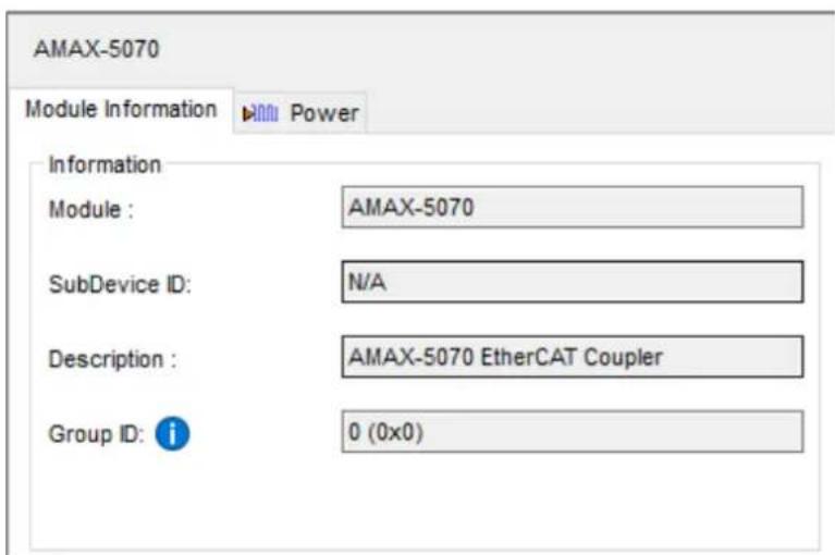
Figure 4.2 Coupler or Coordinator Module Information
4.1.1.2 SubDevice
In the SubDevice, information includes Module, SubDevice ID, and Description (Figure 4.3).
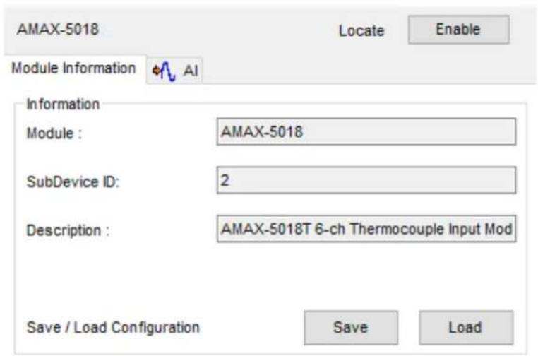
Figure 4.3 SubDevice Information
4.1.1.3 Unknown SubDevices
For Unknown SubDevice, only SubDevice ID can be found (Figure 4.4).
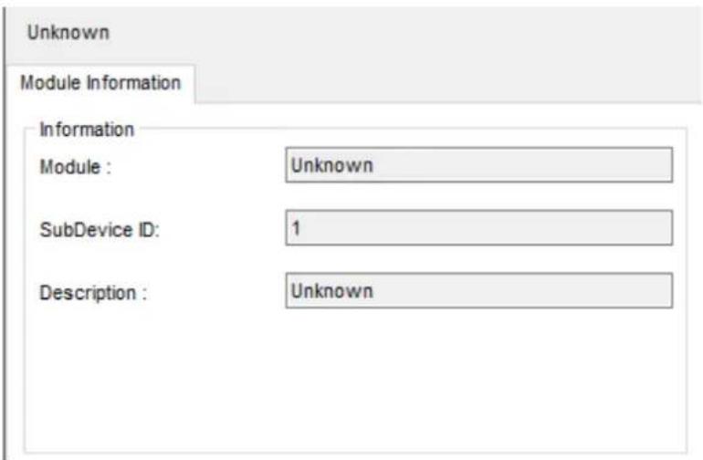
Figure 4.4 Unknown Module Information
4.1.2 Storing and Loading Configurations
When the IO settings of a SubDevice are configurable, regardless of the number of sub-pages, the Load/Save configuration operation can be performed in the Module Information tab. For example, the configuration of the AI tab in the following figure can be saved or loaded through the button (Figure 4.5).

Figure 4.5 Save and Load Configuration
The configuration of DI/DO settings shown in the diagram can also be saved or loaded through the Save or Load button (Figure 4.6).
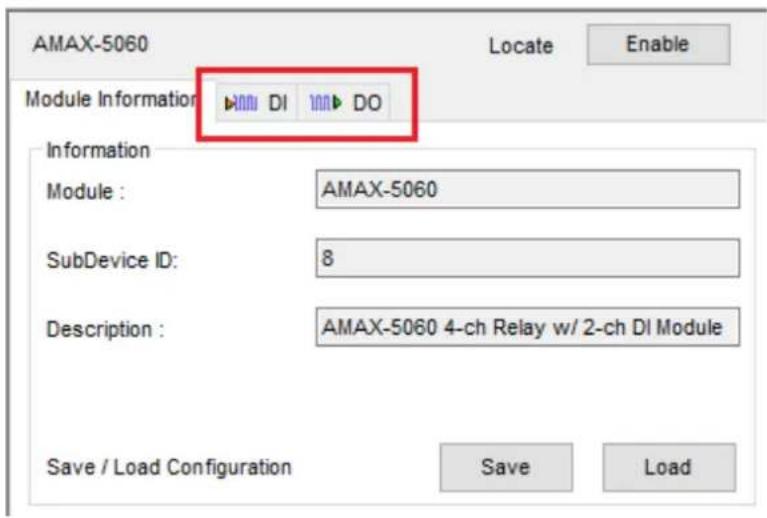
Figure 4.6 DI/DO Configuration
For SubDevices that do not support the save/load configuration feature, the Save and Load buttons will be hidden (Figure 4.7. For example, the AMAX-5056SO only supports setting and reading DO values, but doesn't support any DO configuration functions such as safety functions.
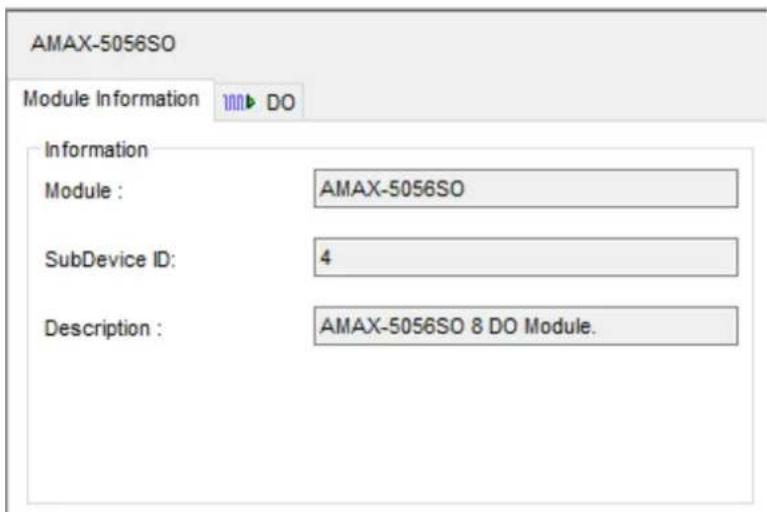
Figure 4.7 Example of Not Supported SubDevice UI
4.1.3 Locate SubDevices
Users can turn on the locate LED on the SubDevice by clicking the Enable button; click again will turn off the locate LED (Figure 4.8.

Figure 4.8 Locating SubDevice Function
For devices that do not support the Locate feature, the locate button is hidden (Figure 4.9).

Figure 4.9 SubDevice without LED Locate Function
4.2 Obtain and Configure Coupler and SubDevice
4.2.1 Obtain Power SubDevices Status
Through the Power tab, you can get the current/voltage related status (Figure 4.10). The Channel information will display the value of current, voltage1, voltage2 and the corresponding Modbus address.

Figure 4.10 Power Status
The tree in Channel Information can be expanded to show more detailed information (Figure 4.11).
| Channel Information | |||
| Name | Value | Modbus Address | |
| Current | |||
| Type | Power | ||
| Current | 0.449 | 4x00008 | |
| Over_Current | 0 | 4x00005 | |
| Voltage1 | |||
| Type | Power | ||
| Voltage_1 | 23.947 | 4x00006 | |
| Over_Voltage_1 | 0 | 4x00001 | |
| Under_Voltage_1 | 0 | 4x00002 | |
| Voltage2 | 0.734 | 4x00007 | |
Figure 4.11 Power Status and Modbus Address Information
4.2.2 Analogue Input SubDevices
4.2.2.1 Obtain Analogue Input Status
Through the AI tab, users can obtain the AI-related status and the Modbus address in the channel information (Figure 4.12).

Figure 4.12 Analogue Input Status
The tree in Channel Information can be expanded to show more detailed information (Figure 4.13).
| Channel Information | |||
| Name | Value | Modbus Address | |
| Ch0 | |||
| Type | AI | ||
| Scale | 760.0 | 4x00106 | |
| Raw | FFFF | 4x00104 | |
| BurnOut | True | 4x00103.0 | |
| UnderRange | False | 4x00103.2 | |
| OverRange | False | 4x00103.1 | |
| Burnout Detect Enabled | True | ||
| Burnout Detect Mode | Up Scale | ||
| Range | J 0~760 °C | ||
| Ch1 | 760.0 | 4x00111 | |
| Ch2 | 760.0 | 4x00116 | |
| Ch3 | 760.0 | 4x00121 | |
| Ch4 | 760.0 | 4x00126 | |
Figure 4.13 Analogue Input Value and Modbus Address Information
4.2.2.2 Configure Analogue Input
Channel information can be configured in different ranges. For example, we want to set the channel 1 input range from K to ±2.5V.
- Expand the channel's tree and the selected Items will be shown in the blue area (Figure 4.14).
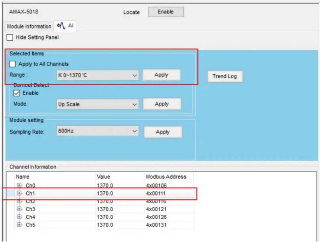
Figure 4.14 Expand the Tree and Change the AMAX-5018 Range
- Select the range ±2.5V and click the Apply button. Users also can apply the setting to all channels (Figure 4.15).

Figure 4.15 Apply the Change for All Channels of This SubDevice
4.2.3 Analogue Output SubDevices
4.2.3.1 Obtain Analogue Output Status
Through the AO tab, users can obtain the AO-related status and the Modbus address in the channel information (Figure 4.16).
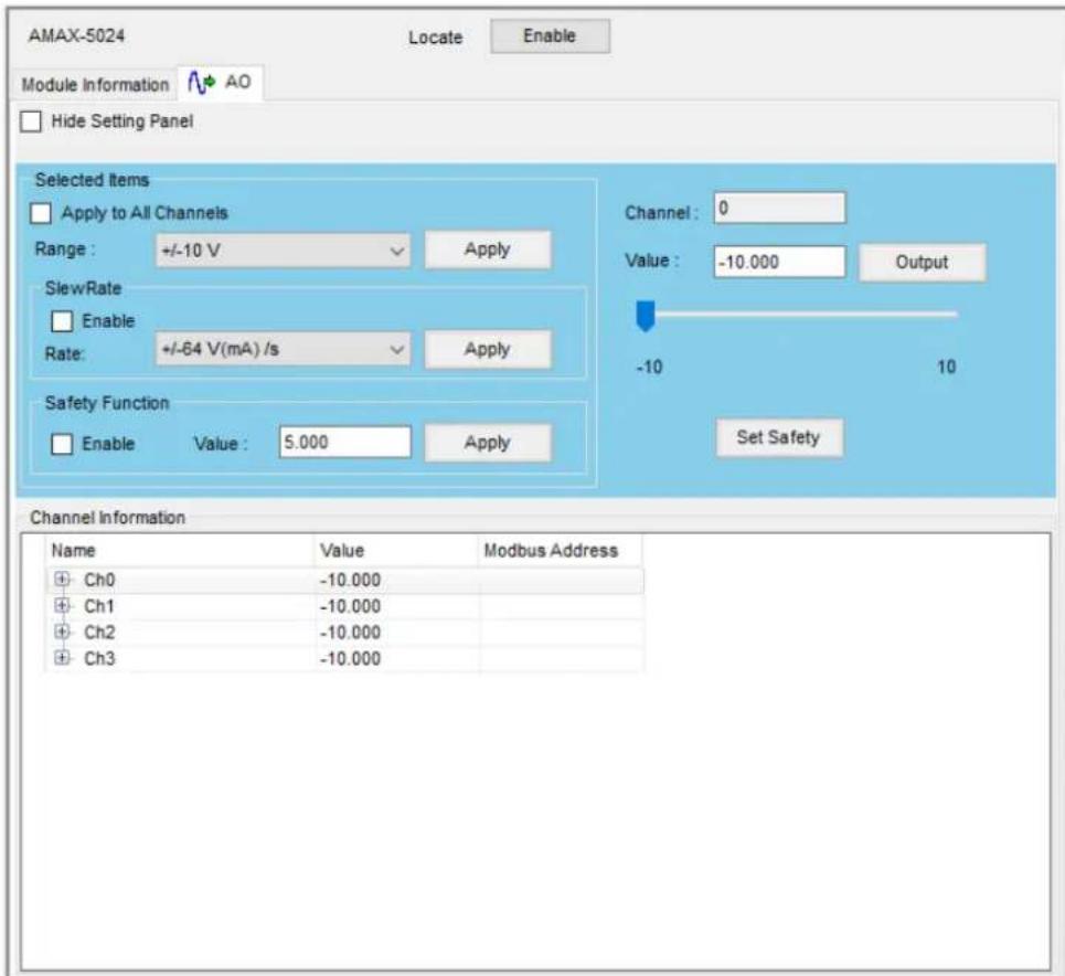
Figure 4.16 Analogue Output Status
The tree in Channel Information can be expanded to show more detailed information (Figure 4.17).
| Channel Information | |||
| Name | Value | Modbus Address | |
| Ch0 | |||
| Type | AO | ||
| ReadBack | 0000 | 4x22014 | |
| ReadBack_Scale | -10.000 | ||
| Output | 0000 | 4x22022 | |
| BurnOut | False | 4x22013.0 | |
| Range | +/-10 V | ||
| Safety Value Enable | False | ||
| Safety Value | 5.000 | ||
| Slew Rate Enable | False | ||
| Slew Rate | +/-64 V(mA) /s | ||
| Ch1 | -10.000 | ||
| Ch2 | -10.000 | ||
| Ch3 | -10.000 | ||
Figure 4.17 Analogue Output Value and Modbus Address Information
4.2.3.2 Configure Analogue Output
Channel information can be configured in different ranges. For example, if we want to change the channel 0 input range (Figure 4.18).
- Expand the channel's tree and the selected Items will be shown on the blue area.
- Select the ranges you want and click the Apply button. Users also can apply the setting to all channels.

Figure 4.18 Expand the Tree and Change the AMAX-5024 Range
4.2.4 Digital Input SubDevices
4.2.4.1 Obtain Digital Input Status
Through the DI tab, user can obtain the DI-related status and the Modbus address in the channel information (Figure 4.19).

Figure 4.19 Digital Input Status
The tree in Channel Information can be expanded to show more detailed information (Figure 4.20).
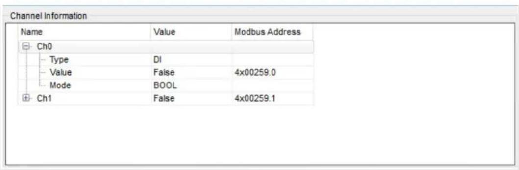
Figure 4.20 Digital Input Value and Modbus Address Information
4.2.4.2 Configure Digital Input
Channel information can be configured in different ranges. For example, if we want to Enable the channel 0 digital filter (Figure 4.21).
- Expand the channel's tree and the selected Items will be shown on the blue area.
- Enable the Digital Filter and Select the range you want. Next, click the Apply button.
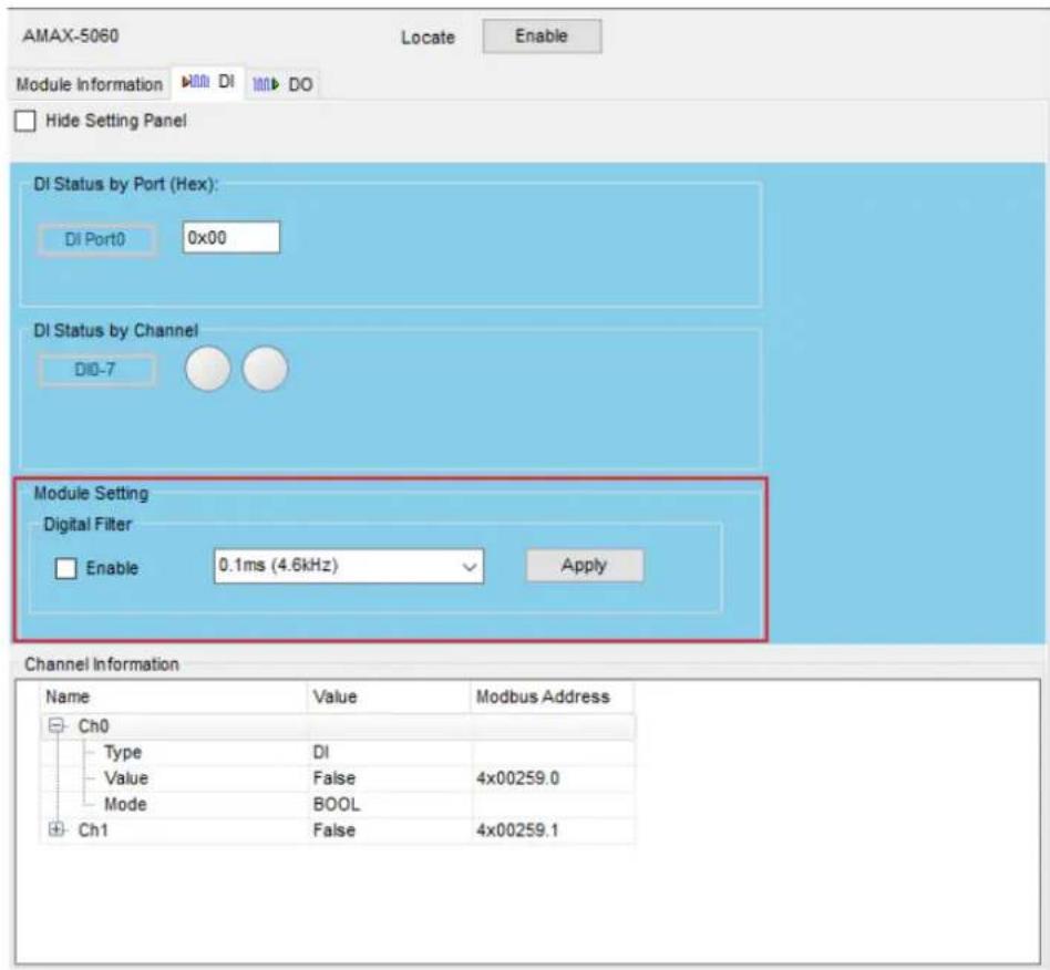
Figure 4.21 Enable AMAX-5060 Digital Filter
4.2.5 Digital Output SubDevices
4.2.5.1 Obtain Digital Output Status
Through the DO tab, users can obtain the DO-related status and the Modbus address in the channel information (Figure 4.22).

Figure 4.22 Digital Output Status
The tree in Channel Information can be expanded to show more detailed information (Figure 4.23).
| Channel Information | |||
| Name | Value | Modbus Address | |
| Ch0 | |||
| Type | DO | ||
| Value | False | 4x00260.0 | |
| Mode | BOOL | ||
| SafetyEnable | True | ||
| SafetyValue | False | ||
| Ch1 | False | 4x00260.1 | |
| Ch2 | False | 4x00260.2 | |
| Ch3 | False | 4x00260.3 | |
Figure 4.23 Digital Output Value and Modbus Address Information
4.2.5.2 Configure Digital Output
Channel information can be configured in different ranges. For example, we want to set the channel 0 output status for high level (Figure 4.24).
- Expand the channel's tree and the selected Items will be shown in the blue area.
- Click the Set True button.
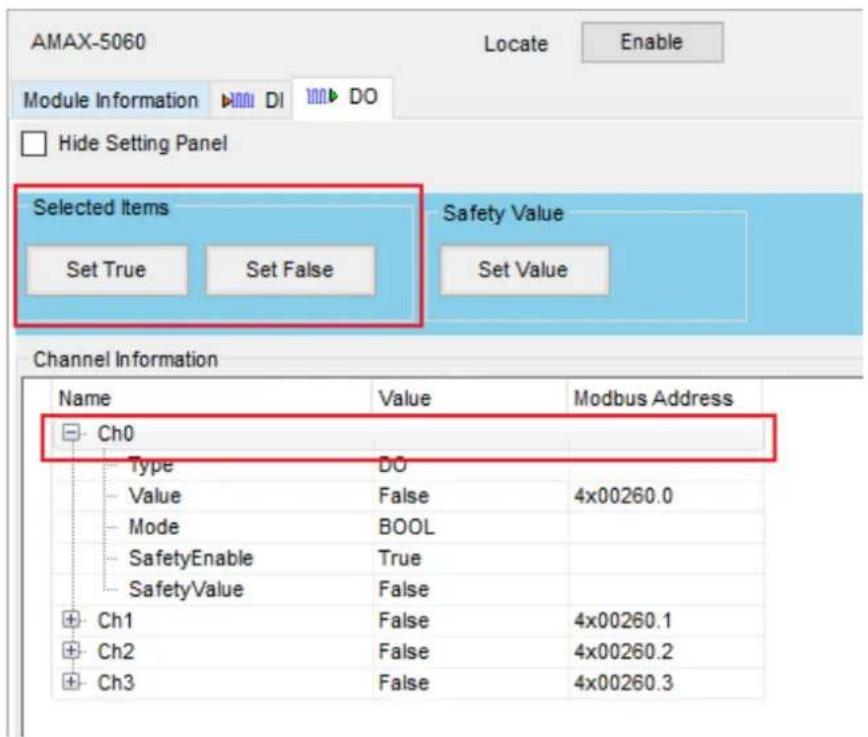
Figure 4.24 Change AMAX-5060 Digital Output Status
4.2.5.3 Configure Safety Value
Supported modules: AMAX-5060.
The safety function is SubDevice will output the safety value when modules disconnect from the MainDevice. The DO safety value can be set when you click the Set Value button (Figure 4.25).
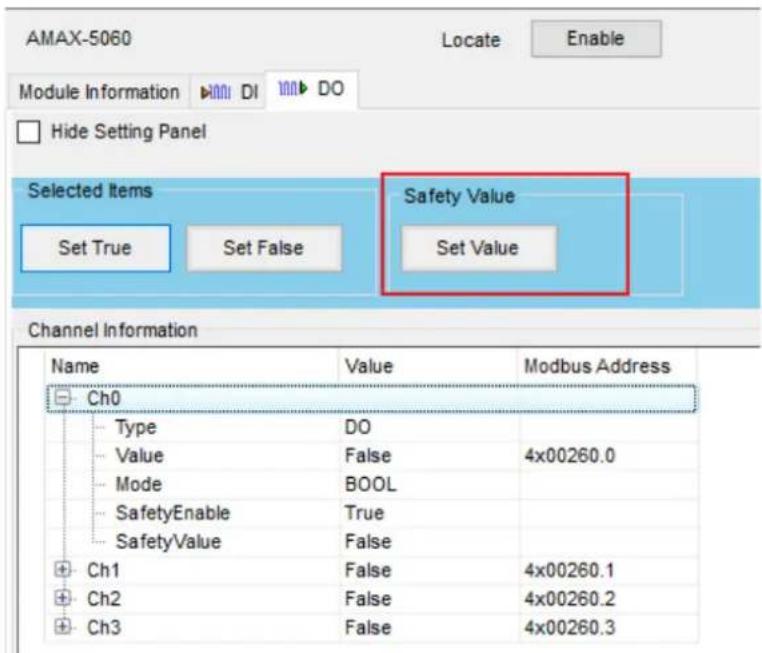
Figure 4.25 Configure AMAX-5060 Safety Value
After clicking the Set Value button, the Safety Setting page will be displayed, and individual channels can be checked for Enable/Safety State. Click the Apply button to save the changes (Figure 4.26).
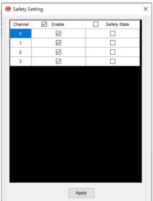
Figure 4.26 AMAX-5060 Safety Setting
4.2.6 Counter/Encoder SubDevices
4.2.6.1 Obtain Counter/Encoder State
Through the CNT tab, user can obtain the CNT-related status and the Modbus address in the channel information (Figure 4.27).

Figure 4.27 Counter and Encoder Status
The tree in Channel Information can be expanded to show more detailed information (Figure 4.28).

Figure 4.28 Counter/Encoder and Modbus Address Information
4.2.6.2 Configure Counter/Encoder
Channel information can be configured in different modes for one channel or all channels.

Figure 4.29 Change AMAX-5080 CNT Mode
External Pin Setting can be set to Latch Counter or Reset Counter. Check the Enable box to apply the function setting. The Latch Value can be found in the Channel Information if the Latch Counter Value is enabled. If you would like to discard the current Latch Counter Value, please click the Clear button (Figure 4.30).
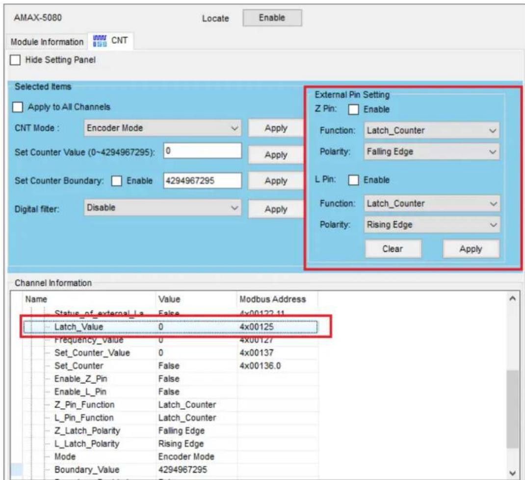
Figure 4.30 Enable the Latch Counter
Chapter 5
Utility Management Tool
5.1 Favorite Group Function
Favorite Group provides saving modules topology for the Utility in order to reduce the rescan time. Utility will load the Favorite Group's data (modules topology) when you restart the Utility. Right-click on the Favorite Group function node, and then click Add New Group in the menu (Figure 5.1).

Figure 5.1 Add New Favorite Group
On the Group page, give the group a name and click Add (Figure 5.2).

Figure 5.2 Create New Group
Right-click on the New Group (This name can be modified by the user), and then click Add New Device in the menu (Figure 5.3).

Figure 5.3 Add New Device for Favorite Group
Select the Ethernet Device tab, change the Module type to AMAX-5070 and key in the IP Address. Click Add for saving change (Figure 5.4).

Figure 5.4 Configure the Ethernet Device
The Ethernet device will appear below the NewGroup node after adding a new Ethernet device. Users can click the Diagnosis Connection to detect whether the device is online or not (Figure 69). If all devices can be detected online the Connect status will display GOOD (Figure 70), if not it will display CorrespondingFail (Figure 71).
![Advantech ADAM/APAX Utility (Win32) Version 2.6.00 (B16 2022/12/22) File Tools Setup Help Serial COM1 COM2 COM3 Ethernet 192.168.56.1 192.168.196.1 172.16.12.64 Other NewGroup NewGroup 172.16.12.98-[NewDevice] ADAM450U_55100Server Windows Sensor Networks NewGroup Connect Title Module COM Addr... Baudrate Protocol Timeout ScanInterval Parity Details Stopbits Ethernet Connect Title Module IP ConnectTimeout SendTimeout RecvTimeout ScanTimeout Account Password GOOD NewDevice AMAX-5070 172.16.12.80 2000 2000 1000 1000 root](/content/2026/05/910341/images/a3c18aeeeb0fbc8825d69816a1aa933b0261eb05207159437d4231e5ab489e17.jpg)
Figure 5.5 New Device Has Been Added Under Newgroup
![Advantech ADAM/APAX Utility (Win32) Version 2.6.00 (B16 2022/12/22) File Tools Setup Help Send COM1 COM2 COM3 Editcom 192.168.56.1 192.168.196.1 172.16.12.64 Others Pocuits Group NewGroup 172.16.12.80 [NewDevice] ADAM4500_5510Roxics Wireless Sensor Networks NewGroup Diagnose connection Serial Connect Title Module COM Addr... Baudrate Protocol Timeout ScanInterval Pority Databits Stopbits Ethernet Connect Title Module IP ConnectTimeout SendTimeout RecvTimeout ScanTimeout Account Password GOOD NewDevice AMAX-5070 172.16.12.80 2000 2000 1000 1000 root](/content/2026/05/910341/images/6919c5a8c28e46154a10c7365ffdaec66a17de90279c3351998cf6ceb3afe10a.jpg)
Figure 5.6 Connect Status is GOOD
![Advantech ADAM/APAX Utility (Win32) Version 2.6.00 (B17 2023/02/13) File Tools Setup Help Serial COM1 COM2 COM3 Ethernet 192.168.56.1 192.168.196.1 172.16.12.64 10.0.0.200 Others Favorite Group NewGroup 192.168.56.0-[NewDevice] ADAM4500_551Gecies Wanlens Scans Networks NewGroup Diagnese connection Serial Connect Title Module COM Addr... Baudrale Protocol Timeout ScanInterval Parity Databits Stopbits Ethernet Connect Title Module IP ConnectTimeout SendTimeout RecvTimeout ScanTimeout Account Password CorrespondingFail NewDevice AMAX-5870 192.168.56.0 2000 2000 1000 1000 root](/content/2026/05/910341/images/c4106567cd2f33ac740449ae02399a3bbc7919bd6a4913616e3c34bcef345ce0.jpg)
Figure 5.7 Connect Status is CorrespondingFail
Users can configure the modules in Favorites Group (Figure 5.8).
![Advantech ADAM/APAX Utility (Win32) Version 2.6.00 (B16 2022/12/22) File Tools Setup Help Serial COM1 COM2 COM3 Ethernet 192.168.56.1 192.168.196.1 172.16.12.64 Others Favorite Group NewGroup 172.16 12.80-[NewDevice] AMAX-5070 Coupler(G0) AMAX-5056SO(S0) Unknown(S1) AMAX-5018(S2) AMAX-5018(S3) AMAX-5056SO(S4) AMAX-5018(S5) AMAX-5018(S6) AMAX-5018(S7) AMAX-5060(S8) AMAX-5080(S9) ADAM4500_5510Series Wireless Sensor Networks Information Setting Modbus Address Setting Communication Diagnosis AMAX-5070 Firmware Firmware Version v1.1.8_70.0.007 Device Name AMAX-5070_Chilis Description Modbus/TCP coupler module for AMAX-5000 Description Support Modules Switch ID Module Description](/content/2026/05/910341/images/78c2327eb468b74651eac6a8f1a7e19bfd989e0df220c1adb33c1c823f450bcf.jpg)
Figure 5.8 Configure the Modules in Favorite Group
5.2 Terminal for Command Testing Function
A terminal for Command Testing Function is supported for users to communicate with SubDevices via Modbus or ASCII command. After searching the Ethernet node, click on the Ethernet node and click the lightning icon (Figure 5.9).
![Advantech ADAM/APAX Utility (Win32) Version 2.6.00 (B16 2022/12/22) File Tools Setup Help Serial COM1 COM2 COM3 Ethernet 192.168.56.1 192.168.196.1 172.16.12.64 172.16.12.39-[ADAM-6717] 172.16.12.48-[ADAM-6760] 172.16.12.52-[ADAM-6050_00DC] 172.16.12.80-[AMAX-5070_Chali] 172.16.12.86-[WISE-4210-AP] 172.16.12.146-[AMAX-5070] 172.16.12.149-[ADAM-6251_00D] 172.16.12.179-[ADAM-6050-NicI] 172.16.12.234-[AIMB-787_ADAI] 172.16.12.250-[ADAM-6224-RDt] 172.16.13.227-[WISE-2834] 172.16.13.228-[WISE-2834] Others Favorite Group ADAM4500_5510Series Wireless Sensor Networks Information Host name: PC100202 Adapter: 192.168.56.1; 192.168.196.1; 172.16.12.64 Connection timeout: 2000 ms Send timeout: 2000 ms Receive timeout: 1000 ms Scan interval: 1000 ms Supervisor password: Apply Support Module : [APAX-5000 Series] APAX-5070 APAX-5071 APAX-5072 [ADAM-5000 Series] ADAM-5000/TCP ADAM-5000L/TCP ADAM-5630 [ADAM-6000 Series] ADAM-6015 ADAM-6017 ADAM-6018 ADAM-6018+ ADAM-6022 ADAM-6024 ADAM-6024-D ADAM-6050 ADAM-6051 ADAM-6052 ADAM-6060 ADAM-6066 [ADAM-6100 Series]](/content/2026/05/910341/images/9c76d276d2178d02cc6673bb6084438eb4cbc89f2743ddf25f4dd234dbc6386d.jpg)
Figure 5.9 Entire the Terminal for Command Testing
Select the AMAX-5070's address and click the Connect button (Figure 5.10).
![Advantech ADAM/APAX Utility (Win32) Version 2.6.00 (B16 2022/12/22) File Tools Setup Help Serial COM1 COM2 COM3 Ethernet 192.168.56.1 192.160.196.1 172.16.12.64 172.16.12.39-[ADAM-6717] 172.16.12.48-[ADAM-6760] 172.16.12.52-[ADAM-6090_000E] 172.16.12.80-[AMAX-5070_Chib] 172.16.12.85-[WISE-4210-AP] 172.16.12.146-[AMAX-5070] 172.16.12.149-[ADAM-6251_00D] 172.16.12.179-[ADAM-6050-NicI] 172.16.12.234-[AIME-787_ADAI] 172.16.12.250-[ADAM-6224-RDt] 172.16.13.227-[WISE-2834] 172.16.13.228-[WISE-2834] Other Favorite Group ADAM4500_5510Series Wireless Sensor Networks Information Host name Adapter: Connect Send time Receive: Scan inter Supervis Support [APAX- APAX] [ADAM- ADAM ADAM [ADAM- ADAM ADAM ADAM- [ADAM-](/content/2026/05/910341/images/2328007d809216f709e41165b7a54fc2d6133886cf509a1325c78c21f9869d3b.jpg)
www.advantech.com
Please verify specifications before quoting. This guide is intended for reference purposes only. All product specifications are subject to change without notice. No part of this publication may be reproduced in any form or by any means, such as electronically, by photocopying, recording, or otherwise, without prior written permission from the publisher. All brand and product names are trademarks or registered trademarks of their respective companies. © Advantech Co., Ltd. 2024


- AMAX-5070
- Modbus/TCP Communication Coupler
- Copyright
- Acknowledgments
- Product Warranty (2 years)
- Declaration of Conformity
- CE
- FCC Class A
- Technical Support and Assistance
- Safety Precaution - Static Electricity
- Safety Instructions
- Contents
- Chapter 1 Introduction......1
- Chapter 2 AMAX-5070 Modbus/TCP Coupler with ID Switch ....7
- Chapter 3 System Configuration .....17
- Figure 3.4 Group ID Conflict....21
- Module Information 21
- Module Setting 25
- Modbus Address Setting.... 31
- Chapter 4 Coupler & SubDevice Config ...... 41
- Chapter 5 Utility Management Tool ......61
- Chapter 1
- Introduction
- Hardware System Diagram
- Power Application and Consumption
- Hardware Installation and Information
- AMAX-5070 Support SubDevices List
- Chapter 2
- AMAX-5070 Specification
- General
- Power Input
- Modbus/TCP Coupler
- Environment
- Reliability Test
- Indicator
- ID Switch
- Pin Definition
- Application Wiring
- Dimensions
- AMAX-5070 Object Dictionary
- Chapter 3
- Connect and Search Modules
- Searching for the Coupler
- Searching for the EtherCAT SubDevice
- Module Information
- E.g.
- Main Node Information page (Coupler)
- Subordinate Node Information page (SubDevice)
- SubDevice Support List
- Module Setting
- Network Configuration
- AMAX-5070 Switch ID
- Rescan the SubDevice and Topology
- Restart the OS of the AMAX-5070
- Cable Redundancy Configuration
- Obtaining the Topology Status
- Modbus Address Setting
- Modbus Addresses for Connected Modules (Fixed Mode)
- Export the List of Modbus TCP Addresses for All Modules
- Modbus Addresses for Connected Modules (Flexible Mode)
- Export the List of Modbus TCP Addresses for All Modules (Flexible Mode)
- Identify the Modules of Abnormal Communication
- Chapter 4
- Coupler and SubDevice Configuration
- Device Categories
- Coupler
- SubDevice
- Unknown SubDevices
- Storing and Loading Configurations
- Locate SubDevices
- Obtain and Configure Coupler and SubDevice
- Obtain Power SubDevices Status
- Analogue Input SubDevices
- Obtain Analogue Input Status
- Configure Analogue Input
- Analogue Output SubDevices
- Obtain Analogue Output Status
- Configure Analogue Output
- Digital Input SubDevices
- Obtain Digital Input Status
- Configure Digital Input
- Digital Output SubDevices
- Obtain Digital Output Status
- Configure Digital Output
- Configure Safety Value
- Counter/Encoder SubDevices
- Obtain Counter/Encoder State
- Configure Counter/Encoder
- Chapter 5
- Favorite Group Function
- Terminal for Command Testing Function
- www.advantech.com
Brand : Advantech
Model : AMAX-5070-A
Category : Programmable Logic Controller