
Vertex IC-V81-W - Loudspeaker ELAC - Free user manual and instructions
Find the device manual for free Vertex IC-V81-W ELAC in PDF.


| Brand | ELAC |
| Model | Vertex IC-V81-W |
| Product Type | In-ceiling speaker |
| Woofer Size | 8 inches |
| Tweeter Size | 1 inch soft dome |
| Frequency Response | 40 Hz – 20 kHz |
| Sensitivity | 88 dB (2.83V/1m) |
| Impedance | 8 ohms |
| Power Handling (RMS) | 100 watts |
| Overall Diameter | 270 mm (10.6 in) |
| Cut-Out Diameter | 231 mm (9.1 in) |
| Depth | 110 mm (4.3 in) |
| Weight | 3.5 kg (7.7 lb) |
| Grille | White, paintable |
| Installation Type | Spring-loaded clamps |
| Material | Polypropylene cone, rubber surround |
| Color | White |
| Application | Home theater, distributed audio |
| Maintenance | Wipe with a dry cloth; do not use solvents |
| Safety | Do not expose to moisture or liquid spills |
| Spare Parts & Repairability | Contact ELAC customer service for replacement parts |
| Warranty | Limited lifetime warranty (depending on region) |
Frequently Asked Questions - Vertex IC-V81-W ELAC
User questions about Vertex IC-V81-W ELAC
0 question about this device. Answer the ones you know or ask your own.
Ask a new question about this device
Download the instructions for your Loudspeaker in PDF format for free! Find your manual Vertex IC-V81-W - ELAC and take your electronic device back in hand. On this page are published all the documents necessary for the use of your device. Vertex IC-V81-W by ELAC.
USER MANUAL Vertex IC-V81-W ELAC
natural_image
Technical line drawing of a speaker or speaker unit with concentric circular components and mounting holes (no text or symbols)
natural_image
Technical line drawing of a circular mechanical component with mounting holes and concentric rings (no text or symbols)
natural_image
Technical line drawing of a circular mechanical component with mounting holes and concentric rings (no text or symbols)
natural_image
Technical diagram of a three-tiered circular component with mounting holes and a central label (no text or symbols beyond the label)OPERATING INSTRUCTIONS
IW-V61-W Integrator Series 6.5" In-Wall Speaker
IC-V61-W Integrator Series 6.5" In-Ceiling Speaker
IW-VC51-W Integrator Series Dual 5.25" In-Wall Center Speaker
IC-VT61-W Integrator Series 6.5" Home Theater In-Ceiling Speaker
IC-V31-W Integrator Series 3.8" In-Ceiling Speaker
IC-V81-W Integrator Series 8" In-Ceiling Speaker
ELAC
The life of sound.
INTRODUCTION
Congratulations on your purchase of these fine loudspeakers and welcome to the ELAC family. Ever since we started in 1926, we have striven to create the very best products available. Our passionate team members are always looking for ways to improve your listening enjoyment. We thank you for making this choice.
These ELAC Integrator Series In-Wall speakers are designed to accurately reproduce the full range of music and film sound, while requiring absolutely no floor space. This compact format is ideal for applications where traditional loudspeakers would be impractical or impossible. In-Wall speakers are ideal for Surround Sound applications, anywhere space is a consideration, or to bring music into additional rooms of the house.
Please take a few minutes to carefully read this manual before you get started. Also, be sure to keep this manual in a safe place should you need to refer to it in the future.
The information contained in this manual is applicable to these six ELAC models
IW-V61-W Integrator Series 6.5" In-Wall Speaker
This speaker is perfect for most applications for Home Theater & Music, providing extremely accurate reproduction of the entire frequency range.
IC-V61-W Integrator Series 6.5" In-Ceiling Speaker
This speaker is perfect for installation in ceilings and provides the same exceptional sound reproduction as its in-wall counterpart.
IW-VC51-W Integrator Series Dual 5.25" In-Wall Center Speaker
This speaker is perfect for the exceptional reproduction of the dialogue in a TV broadcast, music, and the complex requirements of the Center Channel in a Home Theater system.
IC-VT61-W Integrator Series 6.5" Home Theater In-Ceiling Speaker
One of the main challenges during installation is to overcome the narrow directivity of the woofer and tweeter by trying to aim the speaker towards the listener. Some speakers simply provide a swiveling tweeter that can be rotated through a narrow range to "aim" it at the listener. The typical range provided in practice produces almost no change in the sound balance, and does nothing to address the directivity of the woofer. The ELAC IC-DT61-W is designed so that both the woofer and tweeter are mounted at a 30 degree angle that allows the sound to be better directed toward the listening area.
IC-V31-W Integrator Series 3.8" In-Ceiling Speaker
This speaker is perfect for installation in ceilings where sound is rather heard instead of seen.
IC-V81-W Integrator Series 8" In-Ceiling Speaker
This speaker is perfect for installation in ceilings and provides exceptional sound quality for those with demanding needs.
SAFETY INSTRUCTIONS
Use Only As Directed
- Observe all warnings on the speaker and in this manual.
- Please check the speaker for damage before use.
- Carefully consider the proper location before beginning the installation
- Observe the correct polarity when connecting these speakers, according to the instructions in this manual.
Location
- Speakers should be mounted close to, or slightly above ear level whenever possible.
- Allow at least 1.5" of clearance between the wall "cut-out" and any studs or joists
- Please refer to the specification chart for the required depth for each model.
• Use the included template for proper "cut-out" of drywall - Do not install the speaker near any heat sources such as radiators, heating valves, stoves or apparatus (including amplifiers), or in areas where there is a risk of explosion.
- Do not install the speaker near transformers. EMF fields can cause unwanted noise
- Do not install the speaker in locations that are extremely humid, exceptionally hot, cold or prone to vibrations
Overload
- Extreme overload of the device due to very high volume may cause damage to individual components. Because of the possible danger, you should never leave loudspeakers under extreme overload conditions unattended.
Volume
• CAUTION: Continuous high volume may cause severe damage to your hearing. Please listen responsibly.
Disposal
- The packaging is made from recyclable materials. Please be responsible & dispose of these packaging materials in an environmentally sensitive manner.
SPEAKER PLACEMENT
Once installed, In-Wall speakers are not easily repositioned or moved. Please take a bit of extra time to carefully consider the best speaker locations before you begin. Each room is unique, so decide what works best for you.
As a general rule
- Speakers should be mounted close to or above ear level whenever possible
- Speakers should always be directed toward the primary listening position.
- Speakers should be mounted at least two feet from the corners of the room or ceiling.
- Mounting a speaker too near the corner of the room will increase the low-frequency response, causing an unnatural "boominess" in the affected frequencies.
Set-up Diagram #1 – Center Channel & Front Left and Right Channel Speakers
The Center Channel speaker should be mounted close to ear level, above or below the video screen
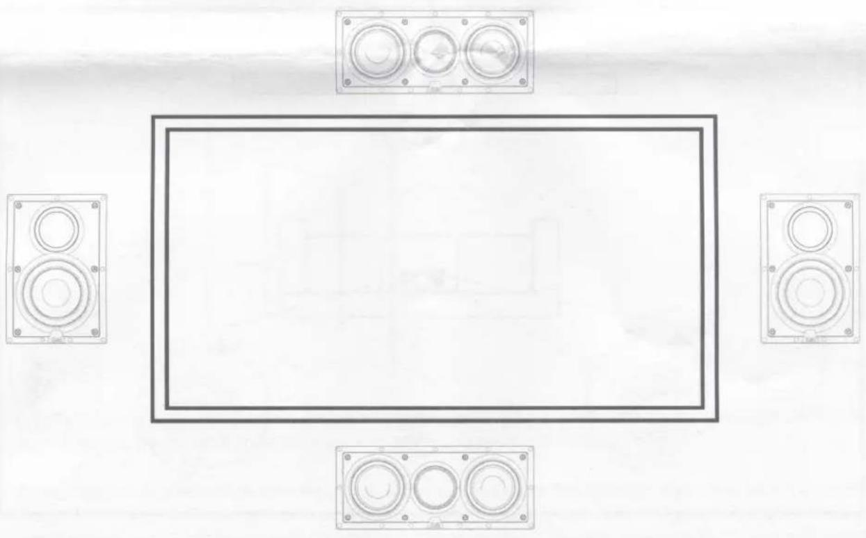
natural_image
Top-down view of a room layout with four speakers and a rectangular frame (no text or symbols)SPEAKER PLACEMENT - continued
Set-up Diagram #2 – Rear Channel Left and Right Surround Speakers
- The rear-channel speakers should be located behind the main listening position and above ear level, if possible.
• These speakers can be either wall-mounted or ceiling mounted, depending on the specific requirements & limitations of your listening rooms design.
• These speakers should be mounted so the tweeter is "aimed" directly at the main listening position. - The rear-channel speakers should be mounted at least 2 feet from the corners of the room. Placing these speakers too near the rooms corners will accentuate the low frequency response

natural_image
Technical line drawing of a vehicle chassis with three wheels and a central seat (no text or symbols)INSTALLATION
Hooking Up The Wires
- For shorter distances up to 25 feet, 18 gauge speaker wire will be sufficient. For longer distances, 16 gauge speaker wire should be used. The speaker terminals will accommodate up to a 14-gauge speaker wire. Leave two feet of extra speaker wire at the speaker end to make installation easier. Do not use nails, staples or other metal objects to secure the speaker wire. The resulting short-circuit could affect your system's performance & could also damage components in your system, especially the amplifier. To minimize interference & external hum keep the speaker wires away from other electrical wires and cables.
- When connecting the speaker wires it is important to retain the correct polarity. Be sure that the wire attached to the "+" red, positive, or hot terminal on your ELAC speaker connects to the "+" red, positive, or hot terminal on the other component.

natural_image
Technical line drawing of a mechanical assembly with no visible text or symbolsMounting the speaker
- Yes, you will be cutting a hole in the wall or ceiling. With the right tools and a little extra preparation & care, installing these in-wall speakers can be quick and easy.

natural_image
Line drawing of a hand holding a tool near a blank rectangular panel (no text or symbols)- Carefully cut out the hole drawn on the paper template. (Note: the inside rectangle (or circle) of the template can be used to shield the woofer while you paint the frame.)
- Next, position the template where you have chosen to mount the speaker and trace along the inside edge. Make your cuts along this line. A utility knife will make clean cuts in drywall. A keyhole saw or electric jigsaw may also be used. Do your best to keep the cuts neat, however the frame will overlap the hole to hide any rough edges.
- At this point, with the wall open, run the speaker cables into position leaving about two feet of extra cable exposed at the opening. Strip the ends of the cable back by approximately 14 inch (6mm) to expose the bare wire.
INSTALLATION - continued
- Attach the speaker cables to the speaker terminals, observing the correct polarity
- Remove the grille from the speaker frame. The grille is held on by magnetic attraction. To remove simply hold the edge of the grille and gently pull toward you.

natural_image
Technical line drawing of a mechanical component with circular features and mounting brackets (no text or symbols)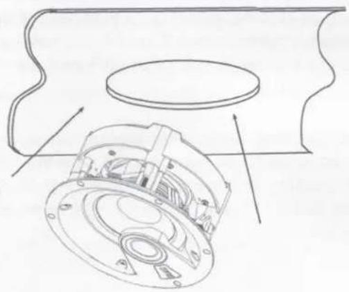
natural_image
Technical line drawing of a mechanical assembly with internal components and mounting brackets (no text or symbols)- With the grille removed, the speaker can be inserted into the mounting hole. First make sure all the tabs are rotated inwards and then connect the speaker wires. The connector posts are spring loaded so the bare ends of the speaker wire can be pushed into the holes on the side of the post after the end cap is depressed. Once inserted the end cap can be released and the wire will be held firm. Make sure no stray strands of wire are exposed that could short across between the two posts.
- Use a Phillips head screwdriver – Turn each mounting screw clockwise to rotate the quick-turn mounting bracket into place. Further turning of the screw will tighten the mounting bracket until it is firmly against the wall. DO NOT over-tighten the screw to prevent breakage of the mounting bracket.
- When the speaker is mounted firmly in place, replace the magnetic grill

natural_image
Line drawing of a hand using a drill to install a multi-tiered speaker into a rectangular housing (no text or symbols)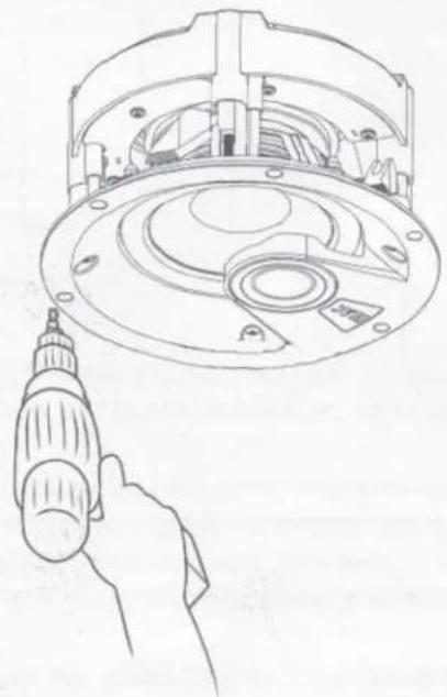
natural_image
Line drawing of a hand holding a drill bit, with an open circular mechanical component above (no text or symbols)SPECIFICATIONS
| IW-V61-W | IW-VC51-W | IC-V61-W | IC-VT61-W | IC-V31-W | IC-V81-W | |
| Tweeter | 1x 1-inch cloth dome | 1x 1-inch cloth dome | 1x 1-inch cloth dome | 1x 1-inch cloth dome | 1x 1/2 inch Soft dome | 1x 1 inch Soft dome |
| Woofer | 1x 6.5-inch polypropylene cone | 2x 5.25-inch polypropylene cone | 1x 6.5-inch polypropylene cone | 1x 6.5-inch polypropylene cone | 1x 3.8-inch polypropylene cone | 1x 8-inch polypropylene cone |
| X-Over Frequency | 2,200 Hz | 2,200 Hz | 3,000 Hz | 3,000 Hz | 3,000 Hz | 2,800 Hz |
| Frequency Range | 45 to 20,000 Hz | 45 to 20,000 Hz | 45 to 20,000 Hz | 45 to 20,000 Hz | 76 to 20,000 Hz | 40 to 20,000 Hz |
| Sensitivity | 89dB @ 2.83 v/1m | 87dB @ 2.83 v/1m | 89dB @ 2.83 v/1m | 89dB @ 2.83 v/1m | 87 dB at 2.83 v/1m | 90 dB at 2.83 v/1m |
| Recommended Amplifier Power | 30 to 120 wpc | 30 to 120 wpc | 30 to 120 wpc | 30 to 120 wpc | 30 to 100 wpc | 30 to 120 wpc |
| Nominal/Peak Power Handling | 50 / 120 wpc | 50 / 120 wpc | 50 / 120 wpc | 50 / 120 wpc | 50/80 wpc | 50/120 wpc |
| Nominal Impedance | 6 ohms | 6 ohms | 6 ohms | 6 ohms | 6 Ω | 6 Ω |
| Binding Posts | Heavy Duty Metal Spring Clip | Heavy Duty Metal Spring Clip | Heavy Duty Metal Spring Clip | Heavy Duty Metal Spring Clip | Heavy-duty metal spring terminals | Heavy-duty metal spring terminals |
| Speaker Finishes | Black Baffle/White Grill, Magnetic Paintable Grills | Black Baffle/White Grill, Magnetic Paintable Grills | Black Baffle/White Grill, Magnetic Paintable Grills | Black Baffle/White Grill, Magnetic Paintable Grills | Black baffle/White Grill, Magnetic Paintable Grills | Black baffle/White Grill, Magnetic Paintable Grills |
| Accessories Included | Cutout Template, manual | Cutout Template, manual | Cutout Template, manual | Cutout Template, manual | Cutout template, manual | Cutout template, manual |
| Dimensions (WxHxD) | 215.3mm x 322.3mm x 102.5mm | 448.3mm x 188.3mm x 85.6mm | 236.5mm Diameter | 265mm Diameter | 108mm Diameter | 285mm Diameter |
| Cut-Out (WxH) | 187mm x 295 mm | 417mm x 157mm | 206mm Diameter | 242mm Diameter | 101.6mm Diameter | 254mm Diameter |
| Mounting Depth | 100 mm | 84mm | 111mm | 173mm | 102.9mm | 113.8mm |
| Weight | 8.9 lbs | 10.7 lbs | 7.1 lbs | 7.3 lbs | 3.1 lbs | 11.9 lbs |
ELAC Americas LLC
North America Limited Liability Warranty
Passive Speakers (No Built-in Amplifier)
ELAC Americas LLC. Warrants to the original purchaser that this product will be free from defects and or workmanship for a period of 3 (three) years from the original date of purchase. During this time, repair or replacement of parts will be free of charge to the original owner. (See below limitations.) Shipping to and return from the repair center will be the responsibility of the original purchaser.
Limitations
• Warranty begins on the date of original purchase from an authorized ELAC Americas LLC dealer.
- Product is warranted only if used in home applications within the maximum power rating specified in this manual. Commercial use of this product is not warranted.
• Product that has been modified or altered in any way will not be warranted.
• Product that has been abused or subjected to faulty equipment will not be warranted.
• Products with defaced or removed serial numbers will not be warranted.
If service is required
In the event that service is required, please contact ELAC America at 714-252-8843 or at service@elac.com to arrange for service or replacement. You will be responsible to provide proof of purchase (copy or original sales receipt). Shipping to and from our repair center will be the responsibility of the original purchaser.
Warranty Outside of North America
This warranty applies to products purchased in the United States and Canada. For warranty claims outside of North America, please contact the local dealer/distributor in the country of purchase.
ELAC
The life of sound.
ELAC AMERICAS INC.
11145 KNOTT AVE. SUITES E & F
CYPRESS, CA 90630
ELAC ELECTROACUSTIC GMBH
FRAUNHOFERSTRAße 16
D-24118 KIEL, GERMANY
- OPERATING INSTRUCTIONS
- INTRODUCTION
- SAFETY INSTRUCTIONS
- Use Only As Directed
- Location
- Overload
- Volume
- Disposal
- SPEAKER PLACEMENT
- As a general rule
- Set-up Diagram #1 – Center Channel & Front Left and Right Channel Speakers
- SPEAKER PLACEMENT - continued
- Set-up Diagram #2 – Rear Channel Left and Right Surround Speakers
- INSTALLATION
- Hooking Up The Wires
- Mounting the speaker
- INSTALLATION - continued
- ELAC Americas LLC
- North America Limited Liability Warranty
- Passive Speakers (No Built-in Amplifier)
- Limitations
- If service is required
- Warranty Outside of North America
- ELAC
Brand : ELAC
Model : Vertex IC-V81-W
Category : Loudspeaker