
PD-171A - Audio player LUXMAN - Free user manual and instructions
Find the device manual for free PD-171A LUXMAN in PDF.


| Product Type | Belt-drive turntable |
| Drive System | Belt drive with AC synchronous motor |
| Platter | 30 cm machined aluminum, 5.0 kg |
| Rotation Speeds | 33 1/3 and 45 rpm (selectable) |
| Speed Adjustment Range | ±5% (independent per speed) |
| Wow and Flutter | ≤0.04% (W.R.M.S) |
| Tone Arm Type | Static balance, S-shaped universal |
| Effective Arm Length | 229 mm |
| Overhang | 15 mm |
| Tracking Error | +1.9° to -1.1° |
| Applicable Cartridge Weight | 4 - 12 g (22 - 32 g with optional heavy counterweight) |
| Anti-skating Adjustment | 0 - 3 g |
| Stylus Light | Detachable high-intensity LED |
| Stroboscope | Reflective view LED type for speed adjustment |
| Power Supply | 230 V ~ 50 Hz, 38 W |
| Dimensions (W x H x D) | 492 × 140 (platter top) × 407 mm (including rear fittings) |
| Weight | 25.4 kg |
| Operating Temperature/Humidity | -5 °C to +35 °C / 5% to 85% (non-condensing) |
| Accessories | Platter, dust cover, headshell, counterweight, rubber mat, belt, EP adaptor, stylus light, phono cable, power cable, tools |
Frequently Asked Questions - PD-171A LUXMAN
User questions about PD-171A LUXMAN
0 question about this device. Answer the ones you know or ask your own.
Ask a new question about this device
Download the instructions for your Audio player in PDF format for free! Find your manual PD-171A - LUXMAN and take your electronic device back in hand. On this page are published all the documents necessary for the use of your device. PD-171A by LUXMAN.
USER MANUAL PD-171A LUXMAN
Features of This Unit 2
Before Use 4
Names and Functions....6
How to Assemble 10
Connections 14
Operations.... 16
How to Replace Tone Arm.... 17
Block Diagram.... 19
Specifications 20
Before Asking for Repair 21
Installation place
- Install this unit in a horizontal and stable place where the unit is less subject to external vibration.
- Do not install this unit near a television or color monitor. Keep this unit away from such devices as cassette decks that are subject to magnetism.
Do not move this unit during playback.
Moving this unit during playback may cause the needle jump, and damage the needle and the record thereby.
When moving this unit
To move this unit, be sure to turn off the power after stopping the turntable and removing the record. Next, unplug the power and phono cables, remove the turntable and the turntable sheet, and move this unit.
Avoid the following locations for installation.
- Locations exposed to direct sunlight
- Places subject to humidity and with less ventilation
- Places where are extremely hot or cold
- Places subject to vibration
- Places subject to dust
- Places subject to oil, steam, and heat (such as kitchens)
Do not put articles.
Do not put any articles on this unit.
To avoid heat emission
Do not place this unit on such device as an amplifier that may emit heat. If the unit is installed on a rack, install the unit as distantly as possible from where the amplifier is installed so as to avoid heat emission from the amplifier and other audio devices.
Dew condensation
Be aware that condensation may occur when this unit is moved from a cold place to a warm place especially in winter or when the temperature of the room where this unit is installed is quickly raised with a heater or the like. It depends on the condensation state, however, this unit can be used after water droplets disappear by turning on the power and leaving the unit as it is for 1 to 2 hours to keep the unit at room temperature.
Even in summer, dew condensation can occur if this unit is directly exposed to cool air from an air conditioner. In such a case, it is recommended to change the installation place.
Lubrication
Do not lubricate this unit yourself because special oil is used for the spindle.
Cleaning
• Usually, wipe the unit with a dry soft cloth.
When the dirt is hard to remove, dip soft cloth in detergent diluted 5 or 6 times with water, wring it well, and remove contaminants. Then, remove the moisture with dry cloth.
- Be aware that acrylic portions such as dust cover may be damaged if the portions are rubbed hard.
- Be aware that printed or painted portions may be damaged if the portions come into contact with alcohol, thinner, benzine, insecticide, or the like. In addition, do not let this unit contact a rubber or plastic form for a long time. That may damage the cabinet surface of the unit.
- When using a chemical cloth for cleaning, read the caution provided with the chemical cloth product.
- Be sure to unplug the power cable from the outlet before cleaning.
Repair and adjustment
When repairs and adjustments are needed, please ask the dealer where you bought the unit.
Features of This Unit
Belt drive
A new drive system is introduced, in which motor-derived noise is attenuated via a belt and smooth rotation is achieved.
Circuit configuration
AC synchronous motor is driven by sine waves coming from 32-bit microprocessor, which are DA converted and amplified by a high-power audio amplifier.
Stroboscope
This unit is equipped with a reflective view type LED strobo-scope to adjust the rotation speed precisely.
Arm base
This unit is finished with chromeplated and spin-stabilized brass with 20 mm in thickness.
By replacing with the optional arm base, various types of tone arms can be mounted, which allows users to enjoy sound changes.
Tone arm
A universal static balance tone arm is included as a standard equipment for the simple cartridge replacement.
Heavyweight platter
The platter weighs 5.0 kg, which is machined from aluminum metal to improve rotational accuracy.
Approximately 0.7 t·cm 2 of moment of inertia has been achieved.
High rigidity main chassis
This unit uses an underslung vibration-damping structure capable of hanging internal main parts using machined aluminum plate with 15 mm in thickness as a base.
Large-sized spindle
This large-diameter spindle is equipped with polyether ether ketone (PEEK) bearing of ball bearing specification that provides stable rotation.
Floating mount
The power transformer and the motor are “floating-mounted” with rubber cushions to isolate vibration to the main chassis.
Hybrid vibration damping
The bottom face of the cabinet has a hybrid vibration-damping structure made of wood and metal for resonance dispersion.
Large-sized insulator
This unit adopts a damper as an insulator that is a combination of rubber and spring, made from different materials to isolate unnecessary vibration coming from an audio rack or others.
Unnecessary vibration from the main chassis itself is also suppressed.
Magnesium alloy headshell
Magnesium alloy headshell with LUXMAN logo is supplied.
LED stylus light
The detachable high-intensity LED stylus light is supplied for operation in the dark.
AC inlet
Power-cable-detachable AC inlet.
Check the accessories.
Make sure that all accessories shown below are in the package.
* No cartridge is included.
- Platter

natural_image
Simple 3D illustration of a circular object with a central dot and two small dots on top (no text or symbols)- Rubber mat

natural_image
Simple diagram of a circular ring with a central dot, no text or symbols present.- Dust cover
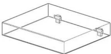
natural_image
Isometric line drawing of a rectangular container with two small protrusions on top (no text or symbols)- Stylus light

natural_image
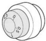
Line drawing of a cylindrical mechanical component with a central shaft and flange (no text or symbols)- Headshell

- Counterweight
- Pulley cover
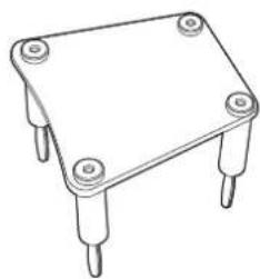
natural_image
Line drawing of a four-legged electronic component with four pins (no text or symbols)- Rubber belt
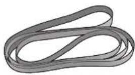
natural_image
Coiled, segmented material resembling a coiled ribbon or fiber (no text or symbols visible)- EP adaptor

- Platter mount handle (2 pieces)

natural_image
Two identical triangular metal tools with handles, no text or symbols visible- Tone arm adjustment wrench (2.5 mm)/arm lifter adjustment wrench (1.5 mm)

- Arm base cover removal wrench (3.0 mm)

- Phono cable securing cushion

natural_image
Three identical 3D rectangular blocks with different surface textures, arranged horizontally (no text or symbols)t8 t10 t12
- Power cable
- Phono cable (ground cable equipped)
* This cable is connected to the main unit at first.

natural_image
Coiled electrical cable with two connectors and a wire, no visible text or symbols• Dustproof cap for stylus light connector
* This cap is mounted on the main unit at first.
- Printed matters
Safety cautions
Owner's Manual (this document)
Names and Functions
Top view
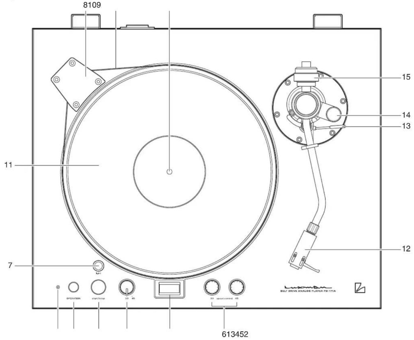
1. Power switch (OPERATION)
This switch turns on and off the power.
2.Operationindicator
This indicator lights up when the power is turned on.
3. Start/stop switch (start/stop)
This switch starts rotating the platter at the selected rotation speed.
This switch also stops platter rotation while the platter is rotating because this switch serves as both start and stop switches.
4. Rotation speed selection switch (33/45)
This switch toggles the rotation speed of the platter between 33 rpm and 45 rpm.
Select a rotation speed in accordance with a record to listen to.
5. Strobo Scope
This window shows the number 33 or 45 depending on the number selected by the rotation speed selection switch. If the number is motionless, the rotation speed is fine-tuned.
6. Rotation speed fine control (33/45 speed control)
33 rpm Fine-tunes the rotation speed. Please look into the stroboscope and fine-tune until the number 33 completely stops moving, when the rotation speed switch is set to 33.
45 rpm Fine-tunes the rotation speed. Please look into the stroboscope and fine-tune until the number 45 completely stops moving, when the rotation speed switch is set to 45.
7. Stylus light connector (light)
This light can illuminate stylus area in a dark room.
Remove the dustproof cap and mount the supplied stylus light.
8. Pulley cover
This cover protects the rotating pulley.
Be sure to mount the cover when the platter is rotated.
9. Center spindle
This spindle is a guide for mounting a record.
For playing an EP record, mount the EP adaptor here.
10. Belt
This belt transfers motor rotation to the platter.
11. Rubber mat
This rubber mat suppresses platter squeaks and brings a record into intimate contact with the platter.
12. Headshell
Headshell couples a cartridge with the tone arm.
13. Arm lifter
This lifter is used to move the tone arm vertically.
14. Anti-skating adjustment knob
This device cancels the inward force applied to the tone arm during record playback.
Select a number in accordance with the cartridge to be used.
15. Counterweight
This weight is used for adjusting tone arm balance and stylus pressure.
Names and Functions
Bottom view
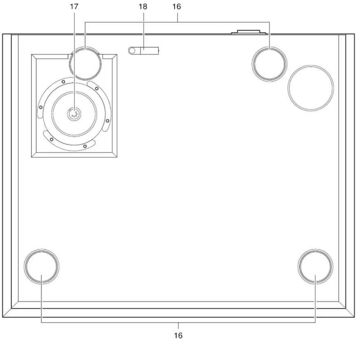
16. Insulator
These support the entire player and absorb howling and vibration from outside.
These insulators are set at the lowest point at first and can be raised by up to 10 mm.
Please use these insulators for making this unit horizontal.
17. Tone arm connector
This connector connects the phono cable to the DIN5P connector of the tone arm.
(The phono cable is connected to the main unit at first.)
18.Cableholder
This holder secures the phono cable.
Rear view

19. AC inlet (AC IN)
Please connect the accessory power cable to supply the power from the AC outlet on the wall.
20.Hingereceiver
This receiver is used for mounting the dust cover. Insert the hinge attached to the dust cover into the hinge receiver at the rear side of the main unit.
Do not turn on the power until assembly is completed.
1. Installation of main body
Install the main body on a rack that is in a position as horizontal as possible.
If the mounting position is inclined, rotate the insulators on four corners of the bottom side to adjust the whole horizontal balance.
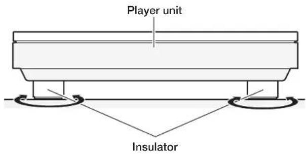
Counterclockwise for up, and clockwise for down.
2. Platter mounting
Engage the supplied platter mount handles in the platter, align the center of the platter with the center spindle while holding the handles, and engage them.
Be sure to use both hands to hold the platter and mount it with extreme care not to apply any unreasonable force to the center spindle.

Please be extra careful to handle the platter because the platter is heavy.
3. Belt wrapping
Firstly, wrap the belt around the turntable. Secondly, wrap the belt that is wrapped around the turntable around the pulley.
Rotate the turntable with your hand a few times, and check to see that the belt is wrapped around the correct position of the pulley.


4. How to mount counterweight
Face the stylus pressure gauge forward and insert the counterweight into the back side of the tone arm until it clicks.

natural_image
Illustration of a hand holding a dial indicator with numbered scales (no text or symbols present)5. How to mount cartridge on headshell
No cartridge is included in this unit. Please mount your cartridge on the headshell. Connect the lead wires (see the table below) to your cartridge and firmly secure the cartridge to the headshell of this unit with the screws and nuts supplied with the cartridge. If the cartridge is loosely secured, hum noise may be generated. Refer to the operating instructions for your cartridge regarding terminals to be connected.
| White Lch+ |
| Blue Lch- |
| Red Rch+ |
| Green Rch- |
The distance from the connection face between the head-shell and tone arm to the tip of the stylus should be 52 mm. Secure the cartridge by moving the cartridge straight along the side face of the headshell and making the cartridge parallel to the headshell.
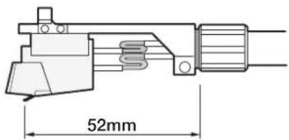
The overhang distance of the tone arm mounted on this unit is 15 mm.
How to Assemble
6. How to adjust horizontal balance
Detach the tone arm from the arm rest to make the tone arm disengaged. Rotate the counterweight to minutely adjust the horizontal balance of the tone arm.
Be aware that the stylus tip of a cartridge is remarkably delicate. Therefore, be extra careful not to apply unreasonable force to the stylus tip.
7. How to adjust stylus pressure
Firstly, set the stylus pressure gauge to 0 while paying attention not to move the counterweight with the tone arm horizontally balanced.
Secondly, set the stylus pressure to a required value by rotating the stylus pressure gauge in the arrow direction shown in the drawing below. Refer to the operating instructions for your cartridge regarding the optimal value. A cartridge weighing 4 to 12 g is suitable for this unit. For a heavyweight cartridge, use an optional heavy counterweight.

natural_image
Diagram of a mechanical device with a rotary dial and handle, showing no text or symbolsThe stylus pressure gauge is free from the counterweight and rotatable freely.
8. How to adjust tone arm height
Change in the height of the tone arm allows for appropriately adjusting the gap between the record surface and the bottom face of the cartridge. Loosen the screw placed at the arm base with the tone arm adjustment wrench, move the tone arm vertically, and tighten the screw when the tone arm becomes parallel to the record surface.

The tone arm is secured only with the screw placed at the arm base. When the screw is loosened, be sure to put the tone arm in the arm rest and use your hand to support the entire tone arm to prevent it from dropping.
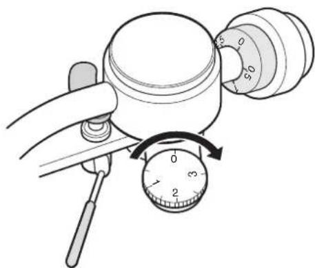
9. How to adjust anti-skating
Rotate the anti-skating adjustment knob to set it to a value that is appropriate to the stylus pressure of your cartridge.
natural_image
Illustration of a hand holding a device with a dial indicator (no text or symbols present)Anti-skating is also called as inside force canceler.
10. How to mount pulley cover
Insert four corners slowly and evenly as shown below.

natural_image
Technical diagram of a mechanical assembly with four vertical supports and a central spring-like component (no text or symbols)11. How to mount rubber mat
The face with a hollow in the center is the upper side. Put the rubber mat on the platter by aligning it with the center spindle.

natural_image
Diagram of a CD or DVD disc being placed on a circular base, showing mechanical components and a downward arrow (no text or symbols present)12. How to mount dust cover
The dust cover has a plug-in type hinge.
Insert the hinge attached to the dust cover into the hinge receiver attached to the rear side of the main unit all the way in a straight manner.

natural_image
Illustration showing two steps of a mechanical assembly: top-down view and hand holding a small component (no text or symbols present)If the acrylic portion of the dust cover is pushed firmly, it may be cracked. Therefore, insert rather than push the hinge portions at the right and left sides at the same time.
Connections

Before Connecting
Before connecting other devices, connect the jack side of the accessory power cable to the AC inlet of this unit.
When connecting, turn off the power switch of this unit and the power supplies of auxiliary devices to prevent unexpected accidents that may be caused by noises.
How to connect power supply
Use the accessory power cable and insert the AC plug in an outlet on the wall in the room where the unit will be installed.
How to connect to phono equalizer, integrated amplifier, or others
Connect the pin plug of the phono cable to the phono terminal of a phono equalizer, an integrated amplifier, or others.
How to connect of grounding conductor
Connect the grounding conductor to the signal ground terminal of a phono equalizer, an integrated amplifier or others to be used.
Failure to observe this may induce hum noises on music signals.
Operations
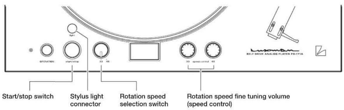
How to play
- Connect the stylus light to the stylus light connector to turn on the light for record playback in the dark.
- Put a record on the platter while aligning the center hole of the record with the center spindle. For an EP record, use the EP adaptor.
- Select a rotation speed (33 or 45) with the rotation speed selection switch in accordance with a record and press the start/stop switch.
- Raise the arm lifter, disengage the tone arm from the arm rest, and move the tone arm to a position where you like to play.

natural_image
Diagram of a mechanical device with directional arrows indicating motion or force (no text or symbols)- Lowering the arm lifter allows the tone arm to be lowered and playback to start.

natural_image
Diagram of a sewing machine with directional arrows indicating movement (no text or symbols)- After playback ends, raise the arm lifter, put the tone arm back on the arm rest, and press the start/stop switch to stop the platter.
To prevent the stylus tip and records from being damaged, use the arm lifter for vertical movement of the tone arm if possible.
By removing the arm base placed on this product (PD-171A) and replacing it with the optional arm base, your tone arm can be mounted. The optional arm bases and applicable tone arms are shown in the table below.
| Product name Applicable tone arm Contents | |
| OPPD-AB1 SME 3009R / 3010R / Series M2-9R /Series M2-9, M2-10 / Series IV, V | Arm base, mounting wrench, arm mounting screw(4 pieces)* 1 , Owner's Manual |
| OPPD-AB2 FR64 / 64S / 64FX, IKEDA IT-345 | Arm base, mounting wrench, Owner's Manual |
| OPPD-AB3 SAEC WE-308 | |
| OPPD-AB4 SAEC WE-407 / 23 | |
| OPPD-AB5 ORTOFON: AS-212S / RS-212D | |
| OPPD-AB6 Universal (no arm mounting hole) |
*1: The attached arm mounting screws (4 pieces) are used for mounting Series M2-9, M2-10, and Series IV and V. Do not use the screws supplied with the tone arm, but use the screws supplied with the optional arm base.
Follow the procedure below to replace the tone arm, and be careful to prevent this product (PD-171A) and arm base from being damaged. Unplug the power cable of this product (PD-171A) before mounting the tone arm.
Follow the operating instructions of your tone arm for adjustments after mounting the arm.
1. How to remove arm and arm base from this product (PD-171A)
Remove the turntable sheet, turntable, and belt from the main unit, and turn the main unit upside down with the dust cover attached. (Spread a soft cloth or the like on a table, and put the dust cover on it.)
Unplug the phono cable of the tone arm from the tone arm.
Loosen the screw of the cable holder that secures the phono cable, and remove the phono cable from the main unit.
After removing the phone cable, put the main unit back to the normal position.
Use the arm base removal wrench (3.0 mm) supplied with the main unit to remove the arm base mounting screws (6 pieces). (Keep the removed screws until they are used to mount the optional arm base.)
2. How to mount tone arm on arm base
Follow the operating instructions of the optional arm base to mount your tone arm to the arm base.
3. How to mount arm base on this product (PD-171A)
Place the arm base so that the golden label on the this product (PD-171A) from which the arm base cover is removed is aligned with the golden label on the arm base to adjust the screw hole position of this product (PD-171A) to the one of the arm base. Use the screws that have been removed from the original arm base to securely tighten them.
Note: If the screws are insufficiently tightened, the sound quality may be adversely affected. Thus, the screws should be securely tightened.
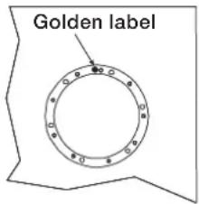
Illustration showing the state of removing the arm base cover from this product (PD-171A)
Align the golden label at mounting on the main unit.
Golden label

Golden label sticking position on the arm base (example)
How to Replace Tone Arm
After completion of mounting the arm base and tone arm, put the turntable, turntable sheet and belt back to the main unit.
4. How to connect and secure phono cable
Connect the supplied phono cable to the tone arm securely. Secure the phono cable using the supplied phono cable securing cushion.
Select a cushion whose thickness is best suited for placement.

5. How to adjust tone arm height
Follow the operating instructions of your tone arm for adjustments.
The following are adjustment examples:
- Adjustment of tone arm height
- Adjustment of Overhang
- Adjustment of lateral balance
- Adjustment of Anti-skating
(also called as adjustment of inside force canceler) - Adjustment of stylus pressure, etc.

flowchart
graph TD
    A["AC Synchronous Motor"] --> B["DAC"]
    B --> C["System Control CPU"]
    C --> D["XTAL"]
    D --> E["LED Driver"]
    E --> F["Start / Stop"]
    D --> G["Speed Selector"]
    D --> H["Speed Control 33rpm"]
    D --> I["Speed Control 45rpm"]
    J["Stylus Light"] --> K["Power TransPower Regulator"]
    K --> L["Output"]
Specifications
| Phono motor section | ||
| Drive system Belt drive system | ||
| Motor Reaction and AC synchronous motor | ||
| Platter 30 cm machined alminum plate (weight 5.0 kg) | ||
| Revolution 33 1/3 rpm, 45 rpm (2 speeds selectable) | ||
| Revolution adjustment range ±5% (each rotation speed adjustable independently) | ||
| Wow and flutter 0.04% or less (W.R.M.S) | ||
| Tone arm section | ||
| Format Static balance, S-type | ||
| Length overall 229mm | ||
| Tracking error angle +1.9° to -1.1° | ||
| Overhang 15mm | ||
| Applicable cartridge weight | 4 g - 12 g * 22 g - 32 g when a heavy counterweight (option) is used | |
| Adjustable height range 38 to 60mm | ||
| Anti-skating 0 to 3g | ||
| Attached equipment and others | ||
| Attached equipment | [Top panel section]Power switch • Start/stop switchRotation speed selection switch • StroboscopeRotation speed fine tuning volume (speed control) (33 1/3 rpm, 45 rpm)Stylus light connector • Arm (arm base mounted)[Rear panel section]AC inlet[Bottom section]Insulator • Tone arm connector (DIN5P type) | |
| Accessories | • Platter • Power cable• Dust cover • Stylus light • Headshell• Pulley cover • Rubber belt • EP adaptor• Rubber mat • Phono cable (connected to main unit)• Counterweight • Platter mount handle (2 pieces)• Tone arm adjustment wrench (2.5 mm)• Arm lifter adjustment wrench (1.5 mm)• Arm base cover removal wrench (3.0 mm)• Phono cable securing cushions (3 types)• Dustproof cap for stylus light connector (connected to main unit) | |
| Power source | 230 V ~ (50 Hz) | |
| Power consumption | 38 W | |
| Weight | 25.4 kg | |
| Dimensions | 492 (W) × 140 (up to top face of platter), 195 (with dust cover mounted) (H) × 407 (10 mm of fittings on rear face included) (D) mm | |
| Ambient operating temperature / Ambient operating humidity | -5 °C to +35 °C / 5% to 85% (non condensing) | |
* Design and specifications are subject to change without notice.
While the unit is used, an unusual phenomenon may be confused as a malfunction for a certain reason. Prior to asking us for our official sole distributor of your country, please check the table below and read the instruction manual. If the cause of the malfunction cannot be identified, please contact your dealer. When we have once accepted your request for repair services, inspection fees and traveling expenses may be claimed even though the unit is found to be normal.
Problem Cause Solution Ref. page
| No power is supplied even though the power switch is pressed ON. | ·The power plug is disconnected from the AC inlet or wall outlet, or it is not inserted firmly. | ·Insert the power plug in the AC inlet and wall outlet firmly. | 15 |
| The platter does not rotate. ·The belt is not wrapped correctly. ·Wrap the belt correctly. 10 | |||
| ·The power switch is not turned on. ·Turn on the power switch. | |||
| The number in the stroboscope moves. | ·The rotation speed is not adjusted. | ·Adjust the rotation speed using the rotation speed fine tuning volume (speed control). | 7 |
| No sound is generated. ·Connection between lead wires and the cartridge or between the headshell and tone arm is incomplete. | ·Make connections of lead wires firmly.Tighten the plug-in nut to secure the connection between the head-shell and tone arm.Mount the tone arm securely. | 11 | |
| The sound volume is too low or too high. | ·The cartridge setting at the phono equalizer, integrated amplifier, and others are not correct. | ·Perform cartridge setting at the phono equalizer, integrated amplifier, and others in accordance with your cartridge (MC/MM). | |
| Sound images are shaky, or sound balance between right and left is not favorable. | ·The player body is inclined. | ·Install this unit in a horizontal and stable place. Use insulators to make this unit horizontal. | 8, 10 |
| ·Anti-skating adjustment is inappropriate. | ·Perform anti-skating adjustment appropriately. | 12 | |
| ·The cartridge is not mounted horizontally. | ·Adjust the horizontal balance. | 12 | |
Problem Cause Solution Ref. page
| Playing speed is inappropriate. · The rotation speed is not adjusted appropriately. | · Select a rotation speed in accordance with a record on the platter, and adjust the speed with the rotation speed fine tuning volume (speed control). | 7 | |
| Hum noises (humm sound) are generated. | · The grounding conductor is not connected. | · Connect the grounding conductor to a GND terminal. | 14 - 15 |
| · Connection of the phono cable is not correct. | · Connect the phono cable correctly. 8, 14 - 15 | ||
| · The cartridge is not mounted securely on the headshell. | · Mount the cartridge on the head-shell with screws and nuts securely. | 11 | |
| Sound skip occurs, or noises (cracking sound) are induced. | · The stylus pressure is not adjusted appropriately. | · Adjust the stylus pressure gauge in accordance with your cartridge. | 12 |
| · A scratch, a warp, or a stain is present on the record. The record is electrostatically charged. | · Do not play a record with a scratch or a warp on this unit. Clean the record with a commercially available cleaner. | ||
| · A stain is present on the stylus tip. | · Remove the stain from the stylus tip. | ||
| · This unit is installed in a vibrating place. | · Install this unit in a horizontal and stable place to avoid sound skip caused by external vibration. | ||
| The stylus light does not light. | · The stylus light is not inserted firmly. | · Remove the dustproof cap and insert the stylus light into the stylus light connector firmly. | 7, 16 |
This unit may not work normally when the unit is subject to external influence such as static electricity. In such a case, the unit can work normally by unplugging the power cable once and plugging it again. If this unit does not work normally even after that, please contact your dealer.
MEMO

- Installation place
- Do not move this unit during playback.
- When moving this unit
- Avoid the following locations for installation.
- Do not put articles.
- To avoid heat emission
- Dew condensation
- Lubrication
- Cleaning
- Repair and adjustment
- Features of This Unit
- Belt drive
- Circuit configuration
- Stroboscope
- Arm base
- Tone arm
- Heavyweight platter
- High rigidity main chassis
- Large-sized spindle
- Floating mount
- Hybrid vibration damping
- Large-sized insulator
- Magnesium alloy headshell
- LED stylus light
- AC inlet
- Check the accessories.
- Names and Functions
- Power switch (OPERATION)
- 2.Operationindicator
- Start/stop switch (start/stop)
- Rotation speed selection switch (33/45)
- Strobo Scope
- Rotation speed fine control (33/45 speed control)
- Stylus light connector (light)
- Pulley cover
- Center spindle
- Belt
- Rubber mat
- Headshell
- Arm lifter
- Anti-skating adjustment knob
- Counterweight
- Insulator
- Tone arm connector
- 18.Cableholder
- Rear view
- AC inlet (AC IN)
- 20.Hingereceiver
- Installation of main body
- Platter mounting
- Belt wrapping
- How to mount counterweight
- How to mount cartridge on headshell
- How to Assemble
- How to adjust horizontal balance
- How to adjust stylus pressure
- How to adjust tone arm height
- How to adjust anti-skating
- How to mount pulley cover
- How to mount rubber mat
- How to mount dust cover
- Connections
- Before Connecting
- How to connect power supply
- How to connect to phono equalizer, integrated amplifier, or others
- How to connect of grounding conductor
- Operations
- How to play
- How to remove arm and arm base from this product (PD-171A)
- How to mount tone arm on arm base
- How to mount arm base on this product (PD-171A)
- How to Replace Tone Arm
- How to connect and secure phono cable
- How to adjust tone arm height
- Specifications
- MEMO
Brand : LUXMAN
Model : PD-171A
Category : Audio player