
H101 - Electronic Tester Seaward - Free user manual and instructions
Find the device manual for free H101 Seaward in PDF.


| Product Type | Portable Appliance Tester (PAT) |
| Brand | Seaward |
| Model | H101 |
| Dimensions (approx.) | 200 x 100 x 50 mm |
| Weight (approx.) | 0.5 kg |
| Power Supply | Mains powered, 230V AC 50/60 Hz |
| Display | LCD with backlight |
| Earth Continuity Test | 200 mA test current, range 0.01-19.99 Ω |
| Insulation Resistance Test | 500 V DC, range 0.01-199.9 MΩ |
| Protective Conductor Current Test | 0.01-19.99 mA |
| Sub-leakage Current Test | 0.01-19.99 mA |
| IEC Lead Test | Pass/fail indication |
| Test Result Storage | Internal memory for up to 1000 results |
| Interface | USB for data transfer |
| Safety Standards | IEC 61010-1, IEC 61557 |
| Ingress Protection | IP40 |
| Operating Temperature | 0°C to 40°C |
| Storage Temperature | -20°C to 60°C |
| Accessories Included | Test leads, mains cable, carry case, manual |
| Warranty | 2 years (subject to terms) |
Frequently Asked Questions - H101 Seaward
User questions about H101 Seaward
0 question about this device. Answer the ones you know or ask your own.
Ask a new question about this device
Download the instructions for your Electronic Tester in PDF format for free! Find your manual H101 - Seaward and take your electronic device back in hand. On this page are published all the documents necessary for the use of your device. H101 by Seaward.
USER MANUAL H101 Seaward
Bracken Hill, South West Industrial Estate,
Peterlee, Co. Durham SR8 2SW. England.
Tel: +44 (0)191-586 3511 Fax: +44 (0)191-586 0227
www.clare.co.uk
sales@clare.co.uk
Limited Warranty & Limitation of Liability
Seaward Group guarantees this product for a period of one year. The period of warranty will be effective at the day of delivery.
In order to ensure the continued performance of this product Seaward recommends that this tester be serviced and calibrated on an annual basis, by Seaward Group or any of Seaward authorised service facilities using Seaward approved parts and components.
Any unauthorized modifications, tampering or physical damage sustained through negligent use or handling will void your warranty.
© Copyright 2017
All rights reserved. Nothing from this edition may be multiplied, or made public in any form or manner, either electronically, mechanically, by photocopying, recording, or in any manner, without prior written consent from Seaward Group. This also applies to accompanying drawings and diagrams.
Due to a policy of continuous development Seaward Group reserves the right to alter the equipment specification and description outlined in this publication without prior notice and no part of this publication shall be deemed to be part of any contract for the equipment unless specifically referred to as an inclusion within such contract.
E&OE
The information contained within this manual is given in good faith and is provided for guidance only. Although all reasonable care has been taken to ensure accuracy of the information, Seaward Group, their agents and distributors, accept no responsibility for any errors or omissions within this document or for any misinterpretations by the user. For clarification on any part of this document please contact Seaward Group, or your local agent, before operating the instrument.
Disposal of Old Product

natural_image
Simple line drawing of a trash bin with crossed lines indicating no waste or plastic discharge (no text or symbols)This product has been designed and manufactured with high quality materials and components that can be recycled and reused.
When this symbol is attached to a product it means the product is covered by the European Directive.
Please familiarise yourself with the appropriate local separate collection system for electrical and electronic products.
Please dispose of this product according to local regulations. Do not dispose of this product along with normal waste material. The correct disposal of this product will help prevent potential negative consequences for the environment and human health.
User Note:
These Operating Instructions are intended for the use of Competent Personnel.
Table of Contents
BEFORE STARTING 6
Safety 7
CHAPTER 1 INTRODUCING THE TESTER 9
Hal 101 9
Hal 102 10
Hal 103 11
Hal 104 12
Hal LED 12
The Front Fascia 13
The Rear Panel (Hal 101) 14
The Rear Panel (Hal 102) 15
The Rear Panel (Hal 103) 16
The Rear Panel (Hal 104) 17
The Rear Panel (Hal LED) 17
Definitions 18
Quick Reference 18
CHAPTER 2 CONNECTING THE TESTER 21
CHAPTER 3 USING THE TESTER 22
How to perform Automatic Tests 25
How to use the Meter Display 38
How to view (search) Test Results 42
How to perform Manual Tests 47
How to download Data (Results) 51
To print Barcode Pass/Fail Labels 56
How to print Barcode Labels and Test codes 57
To print barcode test codes 57
To print barcode Product & Test Type 58
How to use Setup 59
How to use the Memory 73
How to use Help 80
CHAPTER 4 TIPS & TROUBLESHOOTING 82
Power-On Self tests: 82
Temperature monitoring 82
Barcodes 82
Interfacing 83
Downloading to Computer Software 84
CHAPTER 5 MAINTAINING THE TESTER 85
Cleaning the Tester 85
User Maintenance 85
CHAPTER 6 ACCESSORIES 87
Standard Accessories 87
Optional Accessories 88
CHAPTER 7 SPECIFICATIONS 89
Input Rating 89
Earth / Ground Bond Test 90
Insulation Test 90
AC HiPot Test 91
DC HiPot Test 91
Powered Leakage Tests 92
Mechanical 93
Environmental 93
APPENDIX A PURPOSE OF TESTS 94
Insulation Test 94
Hipot Test 94
Ground (Earth) Bond Test 95
Powered Load and Leakage Test 96
APPENDIX B REFERENCE 97
Factory-set Test Sequences 97
TEST CODE TABLES 98
ADDENDUM NOTES 122
HAL Series Remote Connection for Pass/Fail Indications and Remote Fault Reset 122
REMOTE COMMAND PROTOCOL 128
Before Starting
Upon receipt of your HiPot Tester Check, Observe and / or do the following: -
| Part Number | H101 | H102 | H103 | H104 | HLED |
| Tester | 1 | 1 | 1 | 1 | 1 |
| Supply Lead | 1 | 1 | 1 | 1 | 1 |
| HT Clip Lead | 1 | 5 pairs | 1 | 1 | 1 |
| Hipot Probe & Lead | 1 | 1 | 1 | 1 | 1 |
| Guard Plug | 1 | 1 | 1 | 1 | 1 |
| Test O/P Box | 1 | 1 | 1 | ||
| Ground Bond No-Burn Probe & Lead | 1 | 1 | 1 |
1 Read the operating instructions fully before conducting any tests.
2 Data may be lost or altered in virtually any electronic memory under certain circumstances. Therefore Seaward Group assumes no responsibility for financial losses or claims due to data lost or otherwise rendered unusable whether as a result of abuse, improper use, defects, disregard of operating instructions or procedures, or any other allied causes.
3 Seaward Group reserve the right to update the software in instruments returned to them for repair or otherwise, without notifying the customer previously.
Safety
Note
Please read the following Safety Instructions before use!
Safety Precautions
The manual contains specific warning and caution statements where they apply.
A Warning will identify the conditions and actions that pose hazard(s) to the user.
A caution will identify the conditions and actions that may damage the Tester.
Symbols used within this manual and on the Tester are shown below:
 | Risk of electric shock |
 | Warning of potential hazard |
 | Conformité Européenne |
Use of the instrument in a manner not specified may impair safety. Read the following safety information carefully before attempting to operate the instrument.

Warning
Due to the potential hazards associated with any electrical circuit it is important that the user is familiar with the instructions covering the capabilities and operation of this instrument. The user should ensure that all reasonable safety precautions are followed and if any doubt exists should seek advice before proceeding.
This product is designed for use by suitably trained competent personnel and should be operated strictly in accordance with the instructions supplied.
Failure to comply with these instructions may expose the user to electrical hazards.
This Tester performs a number of electrical tests, which involve high voltages and high currents. Never touch the Product being tested, or the test leads, whilst a test is in progress. Never remove the metal enclosure and touch any internal components whilst the tester is turned ON.
Always check all test leads for signs of damage prior to use. Never use damaged or defective leads.
Always ensure the mains supply to the Tester provides an adequate earth (ground) connection.
This manual contains information and warnings, which must be heeded to ensure user safety during operation. It is essential that this manual be read fully before proceeding with any tests.
Should the Tester behave abnormally do not continue with the testing. If during switch on or at any other time the HAL 104 / LED Tester emits a continuous tone, (Note: Not the Test in operation tone) do not continue to perform testing. In both situations disconnect from the mains supply immediately and contact Seaward Group for servicing (see Chapter 5 - Maintaining the Tester).
It is recommended that the correct operation of the HAL is checked at regular intervals by testing against an appropriate Calibration/Checkbox or various test objects with known performance.
Chapter 1 Introducing the Tester
Hal 101
The Clare Hal 101 Tester is a powerful tool to assist in the analysis of the safety of electrical and electronic equipment. A range of tests are provided, with innovative features to aid difficult test situations, which allow testing of a wide variety of equipment.
The Tester is designed to be easy to use, and also includes the following innovative features: -
• Multi-voltage tester
- Stores up to 6000 results including details of Products, user, location, site, date and time in non-volatile flash memory.
• Highly accurate leakage and DC IR measurements.
• Large Full graphics display, Real-time clock
- Connects to PC, Barcode reader and printer
- Compatible with Safety E-Base and other leading software packages.
- Software adjusts the user interface to differing levels of expertise
• Auto test code generation
• Uses fully Barcode reading for simple & easy tests initiation
- Fast Start-up
• Fully isolated test outputs, to comply with EN50191.
Hal 102
The Clare H102 HiPot Tester is an extended product range which encapsulates not only all the benefits and versatility of the original Hal HiPot Tester but also includes more pairs of output test terminals to facilitate multi-channels/multi-points testing capability. This is a powerful tool to assist in the analysis of the safety of electrical and electronic equipment giving it the advantage of speed. A range of tests are provided, with innovative features to aid difficult test situations, which allow testing of a wide variety of equipment.
The Tester is designed to be easy to use, and also includes the following innovative features: -
• Multi-voltage tester
- Multi-Channels output (5 isolated pairs output terminals)
- Stores up to 6000 results including details of Products, user, location, site, date and time in non-volatile flash memory.
• Highly accurate leakage and DC IR measurements.
• Large Full graphics display, Real-time clock
- Connects to PC, Barcode reader and printer
- Compatible with Seaward PATguard and other leading software packages.
- Software adjusted user-friendly interface for differing levels of expertise
• Fully automatic or manually settable test programmes
• Auto testcode monitoring & generation
• Uses fully Barcode reading for simple & easy tests initiation
- Fast Start-up
• Fully isolated test outputs, to comply with EN50191.
Hal 103
The Clare Hal 103 Safety Electrical Tester is a powerful tool to assist in the analysis of the safety of electrical and electronic equipment. A range of tests are provided, with innovative features to aid difficult test situations, which allow testing of a wide variety of equipment.
The Tester is designed to be easy to use, and also includes the following innovative features: -
• Universal Supply Input
- Stores up to 6000 results including details of Products, user, location, site, date and time in non-volatile flash memory.
- Highly accurate Ground Bond, Hipot leakage and DC IR measurements.
• Large Full graphics display, Real-time clock
- Connects to PC, Barcode reader and printer
- Compatible with Safety E-Base, Seaward PATguard and other leading software packages.
- Software adjusts the user interface to differing levels of expertise
• Auto testcode generation
• Uses fully Barcode reading for simple & easy tests initiation
- Fast Start-up
- Fully isolated test outputs, to comply with EN50191.
• 4 wire Ground Bond test measurements
- Usable with the Clare No – Burn Ground Bond probe.
Hal 104 / LED
The Clare Hal 104 Safety Electrical Tester is a powerful tool to assist in the analysis of the safety of electrical and electronic equipment. A range of tests are provided, with innovative features to aid difficult test situations, which allow testing of a wide variety of equipment.
The Tester is designed to be easy to use, and also includes the following innovative features: -
• Universal Supply Input
- Stores up to 6000 results including details of Products, user, location, site, date and time in non-volatile flash memory.
- Highly accurate Ground Bond, Hipot leakage and DC IR measurements.
- Comprehensive Powered Leakage test conforming with the requirements of EN/IEC60990
- Accurate Power and Power Factor measurements
• Large Full graphics display, Real-time clock
- Connects to PC, Barcode reader and printer
- Software adjusts the user interface to differing levels of expertise
• Auto testcode generation
• Uses fully Barcode reading for simple & easy tests initiation
- Fast Start-up
- Fully isolated test outputs, to comply with EN50191.
• 4 wire Ground Bond test measurements
- Usable with the Clare No – Burn Ground Bond probe.
- Automation via the Seaward production line automation software, Safety E-Base
The Front Fascia

The user is provided with a 320 x 240 1/4 VGA Graphical Liquid Crystal Display (LCD). To the bottom of the screen are four function keys which allow the user fast access to options displayed on the Display
There is a rotary encoder used to navigate the menus.
Both side of the rotary encoder is a green and red, start and stop button.
The Hal also has the ability to use non-standard characters, which can be displayed by pressing the 'Symbols' key during text entry. Simply use the encoder to highlight the required character and press the Green button.
The - / + HT sockets on the Front Fascia are the Channel 1 output pair for H102 Unit.
The Rear Panel (Hal101)

Beacon – For connection to external warning beacon (optional item).
Comms 1 – Communication port 1 for connection to a PC.
Comms 2 - Communication port 2 for connection to a compatible Barcode reader or scanner.
Comms 3 - Communication port 3 for connection to a Printer.
The Rear Panel (Hal 102)

Beacon – For connection to external warning beacon (optional item).
Comms 1 – Communication port 1 for connection to a PC.
Comms 2 - Communication port 2 for connection to a compatible Barcode reader or scanner.
Comms 3 - Communication port 3 for connection to a Printer.
The Rear Panel (Hal 103)

Beacon – for connection to external warning beacon.
Comms 1 – Communication port 1 for connection to a PC.
Comms 2 - Communication port 2 for connection to a compatible
Barcode reader or scanner.
Comms 3 - Communication port 3 for connection to a Printer.
Test Output – for connection to remote test output box.
The Rear Panel (Hal 104 / LED)

Beacon – for connection to external warning beacon.
Comms 1 – Communication port 1 for connection to a PC.
Comms 2 - Communication port 2 for connection to a compatible
Barcode reader or scanner.
Comms 3 - Communication port 3 for connection to a Printer.
Test Output – for connection to remote test output box.
Control Ports - Consisting of the following:
- Remote Start/Stop
• Pass/Fail Output
• Digital Outputs x 8 - Analogue Inputs x 8
Definitions
Equipment Under Test - The electrical / electronic apparatus (EUT) which is the subject of testing.
Fast keys - The keys with symbols to the bottom of the screen. These are used to select menu options displayed on the screen.
Tester - The Clare Hal 101 102 103 104 and LED
Un-powered Tests - The EUT is the subject of electrical tests using stimuli generated within the Tester. The EUT is not provided with mains power.
User - The test technician using the Tester to perform tests on a EUT
Quick Reference
Editing the date in all modes
On delivery of the Tester it is necessary to ensure that the correct time and a date are stored. Once stored the time/date is retained in memory and does not need to be entered again. To edit the date: from the MAIN MENU select SETUP, select CHANGE DATE/TIME, use the cursor keys to highlight the digit to be changed. To store the changed date/time setting return to the MAIN MENU. The unit will then display the message STORING SYSTEM DATA.
NB: See Sections on How to use Setup for more detailed Instructions.
Entering a User Name
On delivery of the Tester it is possible to add user names and store in the memory. To edit the user list: from the MAIN MENU select SETUP, select EDIT USER LIST / OPTIONS, use the encoder and select a name, a screen will appear "EDIT USER SETTINGS:, press Green button, use the encoder to enter in the desired name and press GREEN BUTTON to return to the previous menu.
NB: See Sections on How to use Setup for more detailed Instructions.
Editing User Level and Novice Mode
The Tester is delivered with the default setting of novice user level. To change this setting: from the MAIN MENU select SETUP, select EDIT USER LIST/OPTIONS, select USER (Name) from list, select USER LEVEL, select the desired level by selecting either NOVICE or ADVANCED. To store the changed user level setting return to the MAIN MENU. The unit will then display the message STORING SYSTEM DATA.
Storing Product Test Results in Automatic mode
The Product Test Results will not be stored until the end of the test sequence and any COMMENTS menu (if it has been setup) is appropriately acknowledged. The unit will then display the message STORING RESULTS. Your results have now been stored in memory. This will be confirmed when the next Product menu box appears.
Storing Product Test Results in Manual mode
The Product Test Results can be stored by selecting the 'Begin Product' field, when in Manual Mode. Enter a product number, either using the encoder or the barcode scanner, and select OK to start saving the results to that product name. The tester will store the results locally, but will not save these results to the results memory, until the 'End Product' field has been selected. The user will be prompted to enter a comment for the product to be stored.
Storing System Data
System Data consists of everything changed from within the SETUP MENU. To store the System Data return to the MAIN MENU from the SETUP MENU. The unit will then display the message STORING SYSTEM DATA. This will only be done if changes have been made; if no changes have been made then the system data will not be updated.
Waiting for a Yes/Cancel response
When you are prompted to respond with YES or CANCEL (NO) you must use the Fast keys under the display.
Using Symbols in Text Fields
Although there is an option to use non-ASCII symbols as Product numbers, Site & Location descriptions, User names and comments does not guarantee that your computer software will support them. If you are unsure avoid using symbols.
15 Digit Restriction
The maximum Product ID length is 15 characters while the maximum line for the comments is extended to 20 characters per line.
Setting up a Password
The Tester is delivered without any password set up. Therefore it is necessary to set in place an appropriate password for the protection of the System Setup. To do this select Setup from Main Menu, and then select Change Password and you will be prompted for password entry. Also see section on Change Password for instructions.
Remember: Keep the password discreet for use with authorized users only. It may be useful to print the password in Barcode format for quick entry using the Barcode scanner.
Abbreviation used:
Press Green – denotes pressing the GREEN (Start) button
Press Red - denotes pressing the RED (Reset) button
Chapter 2 Connecting the Tester
Connecting the tester
The Tester may be powered by either a 230V or an 115V supply. This is selected on the rear panel of the instrument.
The supply must include an earth connection (e.g. via a 3-pin plug).
When switched on, the Tester will carry out a short self-test procedure (approximately 2 seconds). During this test, the logo will be displayed on screen along with the system version numbers.
The Tester will then display the Main Menu
Chapter 3 Using the Tester
Introduction
Once the start-up procedure of the Tester has been completed, the following screen will appear: -

Navigation through the menus is by dedicated keys: -
| Kev | Function |
| Encoder | Cursor RightCursor Down |
| Encoder anti- | Cursor LeftCursor Up |
| ‘Red’ Button | No / Abort / move back through menu |
| ‘Green’ Button | Yes/Start/Enter/Execute |
There are also the four Fast keys under the LCD whose action will change depending on the function of the Tester at any particular point.
At every start-up the System Setup is Password Protected if a password has been set up. To select an option from the Main Menu, use the encoder or the relevant fast keys command. The selected option will be highlighted by a light-coloured bar. The highlighted selection is activated by pressing the Green button. Depending on current setup you may be prompted to enter in Password at certain stages of navigation or execution of commands. (Important: See notes on Restoring Password Protection)
To perform Automatic test select New Test and to conduct Manual Test select Manual Mode using the fast key button.
Also on the Main Menu screen the current details of the User, Site, Location and Date/Time will be displayed respectively.
If you need to change the current User, Site or Location name use the encoder to highlight CHANGE USER, CHANGE SITE or CHANGE LOCATION and press Green to select from the lists.
It should be worth knowing that a barcode scanner can be used optionally to the encoder for quick entering of products, users, sites, locations, passwords and even comments in barcode format.
Note
The Date/Time will need to be updated only once and this will be retained in memory.
How to....
The remainder of this chapter has been sub-divided into sections to describe the Tester in terms of the essential functions to be performed. A summary is shown below: -
• How to perform Automatic tests
• How to use the Meter display
• How to view Test results
• How to perform Manual tests
• How to Download test results
• How to Print Barcode Labels and Test codes
• How to use Set-up
• How to use the Memory
• How to change User
• How to change Site
• How to change Location
• How to use Help
• How to use a Barcode Scanner
Note
Default settings for User, Site, Location and Test Sequences are pre-loaded into the Tester. See 'How to change...' to select and change these settings and 'How to use Setup' to edit them.
How to perform Automatic Tests
Warning: In order to prevent any unwarranted safety hazards occurring during testing, ensure that the appropriate test conditions are set in accordance to requirements. Proper safety procedures must be in place before performing any Automatic test.
It is important to establish the setup of the current or default test settings in relation to the test conditions formatted. To check or edit these parameters select Setup and then System Configuration.
To perform automatic tests, press New Test fast key or use the encoder to highlight the New Test option on the Main Menu and press Green to display the following menu: -

Use the encoder or a compatible Barcode Reader to enter a Product Number, if configured for use. When using the encoder press the Insert key to enter each character.
Note See Chapter 4 for tips on using barcodes.
Depending on the System Configuration setup and Test type setup different prompt responses may be displayed e.g. Enter Password, Select Test options lists etc.
Once the Product data is entered press Green to display the test Meter screen. Now activate any Test Start Conditions and the test will begin. (See instructions on icons for Start conditions).

Warning: When the test condition is set to 'No Start Condition' it will go straight to the test if the Guard switch is closed.
See relevant chapters on 'How to...' for detailed instructions to select from change lists and refer sub-sections on How to use Setup to edit these fields.
When entering Setup or other Password protected Options Menus you may be prompted to enter your Password. You can use the Barcode Scanner to enter in your authorized password or use the encoder and Insert key to enter it manually.
Once the password is accepted this will unlock all protection to any edit setup fields and including the Password Protection Options formatted in the System Configuration.
Caution: It is recommended to reactivate the Restore Password Protection mode at the Main Menu each time after completing any password accessed Editing menus or Setup changes.


Test Settings
If the user has not fixed the test type in the system configuration the Select Test settings menu will be displayed each time after New Test is pressed and the product number entered.
The user has the ability to: -
- Set a specific test sequence by selecting DEFAULT SEQUENCE
- Allow use of TESTCODES to determine the test to be carried out
- Use any preprogrammed sequences for specific EUTS, e.g. Toaster
Selecting either of the first two options allows settings to be altered. See Default Sequence & Test codes Sequence for instructions to edit test sequence variables.
Selecting any of the remaining 20 options (preprogrammed test settings created by user) allows the user to commence immediately with that test. This will also bring up the test meter screen.
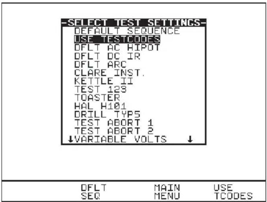
Use the encoder to highlight a Test Sequence Setting and press the green button to select the desired option.
Default Sequence
When you first enter this menu all of the previous values are displayed and one of the field descriptions is highlighted.

Use the encoder highlight a field to be changed and press the Rotate Field fast key to activate the encoder. Rotate Field will be highlighted. Turning the encoder will now cycle through all the available values for the field. To accept desired value press Rotate Field again to deactivate encoder for further field value change (highlight deselected). Again use encoder (or press Next or Previous Field fast key) to move cursor to navigate through to other fields including the three icons fields (see test icon descriptions) for any other changes. Repeat process of 'select/deselect' the Rotate Field key & turning encoder to search for values needed until all desired fields are changed to the user's requirements. Press OK and a message "storing system data" will be displayed. And depending on the test conditions the test will begin with the Meter screen displayed.
Description of Fields setting and Icons for Test Start conditions:
The first field ( 1^st column from left) displays the test code for the test. The test type (e.g. 50Hz Hipot) is shown directly below it. The tests sequence (indicated by the downward arrows) may hold up to 5 unique tests. To add a second test code for example; highlight SKIP, press Rotate Field, turn encoder to select values and press Rotate Field again to accept option. Follow through the arrows to add/delete/edit any levels of test codes sequence if necessary.
The second column holds the test ramp profile times (3 fields) for completing a level of test sequence:
Time up or Ramp Time (to terminal voltage)
Time Hold (for the test at terminal voltage)
Time Down (for final terminal voltage)
The third column indicates the terminal voltage (corresponds to Time up) that the test should ramp to after the ramp up time is reached, and the second voltage (corresponds to Time Down) is the final termination voltage (usually 0.00KV). But this value can be selected to be "Maintained" to sustain the terminal voltage for execution to the next level of test sequence after the first test time sequence has completed. This is done by highlighting the Time Down, press Rotate Field and select "Maintained" using encoder.
The fourth column holds the leakage limit values, low (top) and high (bottom) respectively. A low value is used to ensure that the EUT is correctly connected.
Next the icon (a lightning flash with a number) denotes the Arc level for the test. A level of 1 is the most sensitive to arcs, with 9 the least sensitive, and X disables the feature.
The circular icon with a number in the centre denotes the number of repeats (loops) for the test. This icon can be joined to other levels of test sequence for different combinations of loops cycle for different unique test sequences, see e.g. below
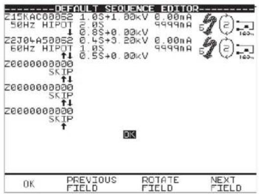
(Fig. A)
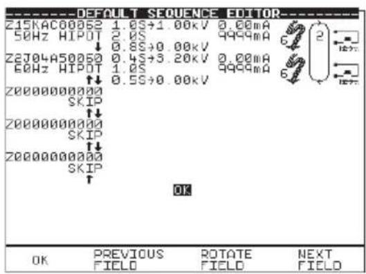
(Fig. B)
Fig. A shows that the first test sequence (50Hz Hipot test) will convene twice before going on to the second test sequence (60Hz Hipot test) for twice. Where as,
Fig. B shows that the first test sequence (50Hz Hipot test) will convene once then proceeds to second test sequence (60Hz Hipot test) once and then the process is repeat again once through.
Therefore you must take caution while selecting (linking) this test repeat loops especially when other levels of test sequence may not be of the same test type nature e.g. DC IR, DC Hipot etc.
For H102 only


Notice that the 1^st test sequence level will show the integers 12345 as default. It may be necessary to edit it for the desired output channels before initiating the test programmes. To select output channels for the next test sequence level you must first create (add) the test sequence level, then bring cursor to highlight bottom of circular icon (the repeat loop, second from right), press Green once will display the integers field on that sequence level. Repeat process as previous page to select/deselect option for output channels.
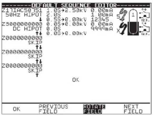

Caution: It must be noted that only the integer(s) selected will conduct the test voltage(s), a blank ‘ – ‘ will be by-passed.
For all units: -
The last icon denotes the Start conditions for the test. They are as Fig.
- Reset External safety guard switch to 'Closed', followed by pressing Green to start each repeat of the test. (Start Ext+Green)
- Reset External safety guard switch to 'Closed', followed by pressing Green once to start the test ( 1^st loop). No subsequent pressing of Green button needed for any repeat tests. Repeat loops will immediately convene whilst guard switch is closed. (Start Ext+Green) for 1^st loop & (Start None) on any repeats.
- Reset External safety guard switch to 'Closed' to start test and each repeat of the test. (Start Ext)
- Reset External safety guard switch to 'Closed' to start the test cycle. No subsequent stimulus needed for repeat tests. Repeats will automatically be performed, whilst the safety guard is closed. (Start Ext) for 1^st loop & (Start None) on any repeats
- Press Green to start test and each repeat of the test. External safety guard switch must remain closed for test to begin. (Start Green)
- Press Green once to start test. No subsequent stimulus needed for any repeat loop tests. Repeat loop tests will automatically start. External safety guard switch must remain closed for test to begin. (Start Green) for 1 ^st loop & (Start None) on any repeats.
- No start stimulus required. The test begins immediately after the product data has been entered. This mode is usually a follow-on test from a previous test. Use this with caution. (Start None) for all tests
Fig. 1 Fig. 2 Fig. 3 Fig. 4 Fig. 5 Fig. 6 Fig.7

Use Test codes
This option bypasses the need to edit a specific test sequence, allowing direct entry of a Test code through the barcode scanner. From the Select Test Setting menu choose Use Test codes or press Use Tcodes fast key.
Use the encoder to highlight the Test code sequence (up to 5 levels) to be changed and use a barcode scanner to enter in a Test code.
Press OK to accept & save Test code option.
OR press the Red button to abort and return to the previous menu.

NB: The Test code numbers can also be changed using the encoder. First highlight the test code to be edited, press Green button to bring up the alpha-numeric options on the screen. Use Rotate cursor & Insert keys to enter any combination of test codes sequence. However incorrect test codes will be rejected and activate a warning. See Test code tables for details.
Perform Test
Use the encoder to highlight the OK field and press Green to perform the test. Pressing the Red Button will return to the previous menu.
The screen will change to the Meter Display (see separate section - How to use the Meter Display for an explanation).
Note
Help screens may be displayed depending on the User Level set. It is possible to stop these appearing by altering the User Level. See EDIT USER LIST OPTIONS. Help can be displayed during any test by pressing the appropriately marked fast key.
All automatic mode test results are stored in memory.
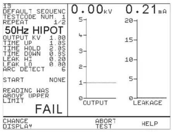
If any test in the test sequence fails, then the test sequence is aborted and a fail message will be displayed with the alarm buzzer beeping continuously. Press Green to acknowledge the status. A Failure Options Menu can be configured or just a Failure Comments box option can be selected at the System configuration setup to indicate these modes.
bar
13 DEFAULT SEQUENC TESTCODE NUM. 1 REPEAT 1/2 50Hz HIPOT OUTPUT KV 1.00 TIME UP 1.0S TIME HOLD 2.0S TIME DOWN 0.8S LEAK HI 0.20 LEAK LO 0.00 ARC DETECT 6 START NONE READING WAS ABOVE UPPER LIMIT FAIL CHANGE ABORT HELP DISPLAY TEST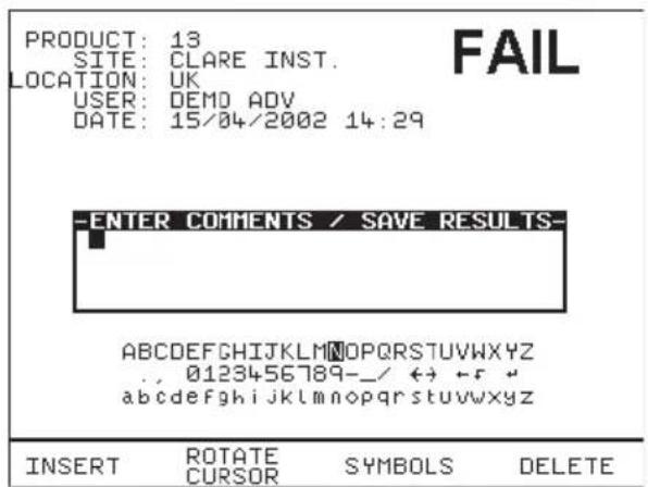
Fail Comments – Use encoder & Insert key to enter in any comments. To skip line or move to next line, highlight Rotate Cursor and turn encoder. Or use barcodes.
Enter Green button to store results/comments.
During an automatic test the user may choose to abort test by opening the Guard switch or pressing the Red button. See Abort action for detail.
However if an Abort warning signals during any test indicating an interruption detected due to Over current, Arc detected or any other reason that causes a tester system fault the test will be aborted immediately with the buzzer beeping continuously until the Green or Reset button is pressed. Then the Abort Options box will show. Select Abort Product to exit from test programme. This will ensure No test results are stored against the product number. In any case Do Not press Abort Test as this will store an empty record to the product data memory.

line
ABC10000 DEFAULT SEQUENC TESTCODE NUM. 1 REPEAT 1/1 50Hz HIPOT OUTPUT KV 2.50 TIME UP 2.0S TIME HOLD 10S TIME DOWN 2.0S LEAK HI 6.0 LEAK LO 0.00 ARC DETECT 0 START EXT+GREEN ABORTED - OVER CURRENT 0.00kV 0.02mA 5 4 3 2 1 0 OUTPUT LEAKACE CHANGE DISPLAY ABORT TEST HELP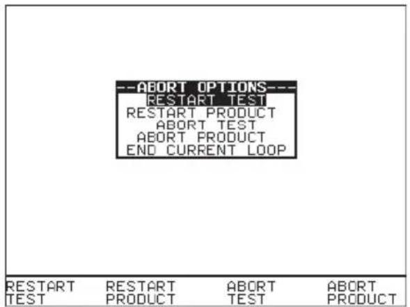
Add Comments

When a test has completed you can add/enter comments reference to the Product number. See system configuration setup to select this option. Use the encoder or barcode scanner to enter comments into the box. Select Rotate Cursor and turn encoder for a new line. To store the comments press Green. Your results and comments will now be stored.
Options after Test
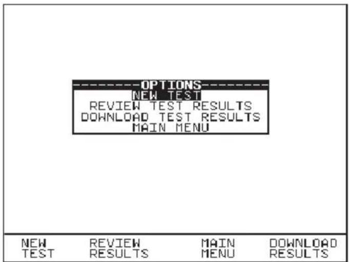
The options menu is selected by entering 'After Test: Menu' in the System Configuration Setup. With this option the following screen is displayed when an Automatic sequence has been completed.
Use the cursor keys to highlight an option after test and press Green to select the desired option.
New Test
This is to perform a new test. Enter in the product number will begin the test.
Review Test Results
This option displays the results from the test in tabular form: -
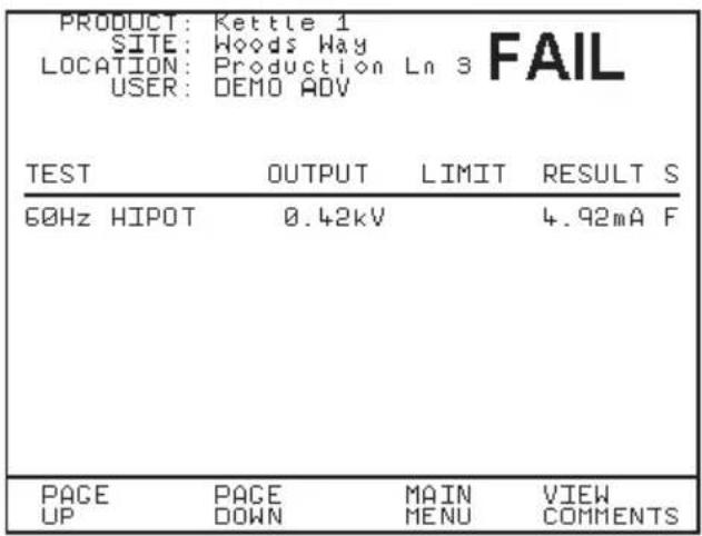
Select View Comments fast key will display the comments stored.
Use the Red button to return to the previous menu.
Download Test Results
When selected a Download Options menu displayed will allow user to download results to a list, pass/fail labels or barcodes using a compatible printer - See section on How to download data for formatting information.
Press OK to start the download. The following message will be displayed.
DOWNLOADING DATA...
If there are problems downloading e.g. due to interfacing problems, then after a delay, the following error message appears: -
WARNING
PRINTER TIMEOUT: NO PRINTER CONNECTED PRESS START KEY TO CONTINUE
Press the Red Button to return to the previous menu.
Abort Actions
During an Automatic test, opening the guard switch or pressing the Red Button immediately stops the test in progress and displays the Abort Options menu: -
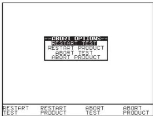
Use fast key functions or the encoder to highlight an action following abort and press the green button to select the desired option.
Restart Test
Restart the current test.
Restart Product
Restart the first test in the test sequence for the current Product.
Abort Test
Abort the test without storing a test result and select the next test. Caution: Depending on the test Start Conditions set pressing this key will immediately start the next test sequence without warning.
Important: Do not select or press this option if previously the test had been aborted automatically by the tester due to Over current or Arc detected or any other fault condition.
Abort Product
Abort the test sequence and select a new Product.
End Current Loop
End the current test-loop and proceed to the next test sequence. May also mean end of current loop for the current channel if more channels are defined by the test code, then the test loop will restart using the next channel.
How to use the Meter Display
The Meter screen is displayed prior to tests commencing in both Automatic Mode and Manual Mode (shown here): -

bar
BEGIN PRODUCT 50Hz HIPOT OUTPUT KV 1.50 TIME UP VAR. TIME DOWN 1.0S LEAK HI 5.00 LEAK LO 0.30 ARC DETECT 0 START HOLD (VARIABLE) 12.6s HV 0.75KV 0.14mA OUTPUT LEAKAGE CHANGE ABORT HELP DISPLAY TESTThe screen can be considered as two panels, left and right. In the left panel the information is from top to bottom, as follows:
Begin product – this is displayed for manual mode only, if a product number entry is required select this to enter details and it will be displayed above this line. Note: Only tests results with associated product details will be stored in memory.
For automatic mode the product number, test filename, test code sequence number and test repeat loops are displayed here. See sample
Test type, in this case 50Hz AC Hipot. This could be 60Hz AC Hipot, DC Hipot, DC IR Ground Bond tests (50Hz EBond or 60Hz EBond) Load / Power Leakage Test or Load / Power Touch Leakage.
Output kV – this is the target output voltage value to be reached after the ramp up period.
Time up – this can be set to a specific value using the encoder, or as in this example to be Variable (i.e. no time limit set – test terminated by pressing Green or safety guard being released). When variable mode is selected, turn encoder to achieve the output voltage, then press Green to stop test.
Time hold - this can be set to a specific value using the encoder.
Time down - this can be set to a specific value using the encoder.
Leak Hi – this is the upper limit for the leakage current.
Leak Lo - this is the lower limit for the leakage current. It is used to determine that a EUT is correctly connected.
Arc detect – this shows the level set for the detection of any arc that may occur in the EUT, during testing.
Start – shows the action needed to initiate the test sequence. This refers to the usage of the external safety guard switch only, the external guard switch and the Green button or the Green button only.
Test status – here this shows that the test is in the hold phase. This part of the display is used to indicate what part of the test cycle is being performed.
Elapsed test time – this is shown below the test status.
HV icon – this is displayed to show that a voltage is being generated by the tester, and if connected, will appear at the EUT.
⊕ 1 ⊕ (Hal 102) This icon indicates which active terminal output channel pair is selected.
-5
(Hal 103/104/LED) This icon denotes that the front HV +/- sockets is the active test output port and will carry the test voltages during test. This icon corresponds to F (front) port field selected in the test sequence editor window.
图图
(Hal 103/104/LED) This icon denotes that the active test output port selected is the rear socket which must only be connected to the Seaward test output box provided. This icon corresponds to R (rear) port field selected in the test sequence editor window.
Note: if both the F & R icons are enabled, the tester will perform the test twice, once for the front output and then the rear output with a prompting in between the tests.
Note: With respect to the Hal 103, 104 and LED, Ground Bond or Earth Bond Test the test output port is not selectable and Test voltages will only be active at the rear socket via the test output box.
The right panel of the display shows the output voltage and leakage current or insulation resistance, depending on which test is being applied.
The bar graphs are clearly marked, and include dashed lines to indicate the limit points. At the top of each bar graph there is a numerical display of the actual value.
Press Change Display - allows the right panel to be changed to display the readings via large high visibility DVM style displays, see below:

E.g. of Ground Bond (EBOND) Test Meter Screen:-

Sample Automatic Mode Meter Display
The screen will be similar to that for manual mode as described earlier. However there are a number of extra features denoted as follow:-
I^st line (18) – Product number
2^nd line (Toaster) - the Test type
3^rd line denotes the Test code Sequence number, in this case it has only one level setup. A maximum of 5 levels could be setup.
4^th line denotes the specific test of a repeat loop being done. Shown here 1/5 means 1^st test of FIVE test loops being carried out. This corresponds to the circular icon with a number in the centre as mentioned in Default sequence description.
⊕ 1 ⊕ (Hal 102) This denotes the active terminal output channel pairs that the test voltage will conducted to.

bar
18 TOASTER TESTCODE NUM. 1 REPEAT 1/5 50Hz HIPOT OUTPUT KV 1.25 TIME UP 1.0S TIME HOLD 1.0S TIME DOWN 0.5S LEAK HI 20.0 LEAK LO 0.00 ARC DETECT 0 START GREEN HOLD 1.7s HV ⊕1⊕ CHANGE ABORT HELP DISPLAY TEST HELPHow to view (search) Test Results
To view test results stored in memory, press View Data fast key or use the encoder to highlight the View Test Results option on the Main Menu and press Green to display the following Search menu: -

Use the encoder to highlight the required search parameters and press Green to select the desired search field. A ‘*’ denotes all product test results related to the field parameter. To get Quick search pressing Start Search now on the default screen without selecting any specifics will display all results in the memory. Use Page Up/Down to see the full list.
Search result through Product Number
Enter a Product number to search for the specific results. If the Product number field is left blank then the character ‘ * ’ will be inserted as default, indicating to search for all of the Products. Press Start Search to begin. Alternatively use a Barcode scanner to enter a specific product number for the search and press Start Search. A search results will be displayed. A message No Records Found will be shown when products number is incorrect or when other field’s data could not be matched. If unsure use ‘ * ’ for the search.
Search result through Site Name
At the Search for Data menu highlight Site and press Green to display the site list. Highlight the Site name to which previously the products could have been tested on and press Select Site. Back at the search menu press Start Search to begin. A search results will be displayed.

Search result through Location Name
At the Search for Data menu highlight Location and press Green to display the location list. Highlight the Location name to which previously the products could have been tested on and press Select Location. Back at the search menu press Start Search to begin. A search results will be displayed.

Search result through User Name
At the Search for Data menu highlight User and press Green to display the User list. Highlight the User name to which previously the products could have been tested on and press Select User. Back at the search menu press Start Search to begin. A search results will be displayed.

Test Status
When Test Status is highlighted use the Green button to select the option required, each time you press Green a different option will be displayed. This can be PASS, FAIL or ‘*’ which indicates both.
Storage Status
When Storage Status is highlighted use the green button to select the option required, every time you press Green a different option will be displayed. This can be NORMAL status, DELETED status or ‘ * ’ which indicates both.
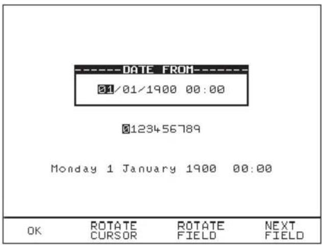
Date From
This option allows the user to search for test results after the selected date. Use the cursor keys to highlight the digit to be changed. Use the encoder to change the value. Select OK to store the settings or press RED to abort them.
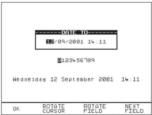
Date To
This option allows the user to search for test results before the selected date. Use the encoder to highlight the digit to be changed. Use the encoder to change the value. Select OK to store the settings or press RED to abort them.
Start Search
After all the search parameters have been set, press Start Search to begin the search. It should be noted that unsure parameter should not be used otherwise this will corrupt the search matching process.
Search Result
When you select Start Search the following screen will be displayed. This screen indicates the Products that match the search criteria.

You can delete the highlighted Product by pressing the delete key.
Product Test Results
It is possible to view the results obtained for a certain Product by highlighting the Product number and pressing Green.
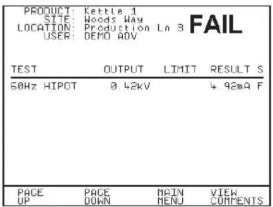
Pressing the View Comments fast key will display the Comments box. Use the Red button to return to the previous menu.
How to perform Manual Tests
Manual mode provides the user with direct access to the tests. In this mode individual tests can be selected and performed. Product numbers, sites, users and test codes can still be assigned to Products if required; though this is not essential.
Entering Manual Mode
Use the fast key to select Manual Mode from the Main Menu.
The system will then display the meter screen and allow direct use of the default, or last selected test that was setup. The user may setup 10 unique configurations, and save these for later use. To operate the test the operator must follow the on screen instruction; closure of the safety guard switch, followed by pressing Green. The test may be terminated at any time, either by pressing Red, or opening the safety guard.
Manual mode is primarily intended for use in evaluating EUTs in a laboratory environment, or for performing production line re-testing.
Note
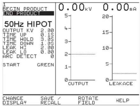
To store tests in memory from Manual mode you must first select BEGIN PRODUCT, perform the tests required for the EUT. When you have completed the required tests select END PRODUCT, upon leaving this option the unit will now store the results. Note that the Enter Comments option is not displayed until there is something to store. Tests carried out without Product details being entered will not be stored

line
BEGIN PRODUCT END PRODUCT 50Hz HIPOT OUTPUT KV 2.00 TIME UP 0.1S TIME HOLD 3.0S TIME DOWN 1.0S LEAK HI 2.00 LEAK LO 0.00 ARC DETECT 0 START GREEN 0.00kV 0.00mA 5 4 3 2 1 0 OUTPUT LEAKACE CHANGE SAVE/ROTATE HELP DISPLAY RECALL FIELD HELPCreate Product Number
This allows all manual tests performed to be stored against the Product number until the Product number is changed.

Use the encoder or a compatible Barcode Reader to enter a Product Number. Use the encoder to select the 'BEGIN PRODUCT' field, then you will be presented with the screen above.
If you need to change the current User, Site or Location profile, return to Main Menu to select from the desire Change lists. Any test results saved against the current profiles will be stored in memory. Old results data will not be altered.
Note
Default settings for Sites and Test Sequences are pre-loaded into the Tester. See 'How to use Setup' to change these settings.
Use the encoder to enter comments into the comments box (4 lines of 20 characters). Press Green for a new line. To store the comments press the OK Fast key. Use the Red button if you do not want to store the comments.
Performing a Manual Test
After selecting the manual test display, you can set test parameters.
The user can change an individual field setting when the field is shown highlighted (use encoder to highlight any fields to be changed). Then press Rotate Field fast key (highlighted when selected), and use the encoder (to cycle through) to change the variable in the selected field. Before moving to next field you must deselect Rotate Field. Repeat process until all desired field settings are selected as required.
Now these manual test settings can also be saved to a list of file names (max. of ten) which can be recalled for future tests. Press Save to save current setting to highlighted file or select a previously saved file and press Recall will bring those settings to the manual test display screen.

Use Edit Name key and the encoder to edit any file name if necessary.
To start the test, select (highlight) the 'START' field, close the safety guard and then press Green. Pressing Red or Abort Test fast key will abort the test at any time.
If User wishes to print out the test results immediately after the test, pre-select the After Test: Download option at System Configuration setup. Alternatively any stored test results can be printed through the Download Results option at Main menu.
Note
In manual mode you will not get Abort Options, when Abort stimulus is initiated the test will simply stop and revert to the Meter display. The aborted test will not be stored.
If a Product Number has been created, the test result will be stored under the entered number. To store tests to memory choose Enter Comments / Save Results.
Enter Comments/Save Results
When you have completed a test you can enter comments which will be referenced to the Product number. To select this option, at System configuration setup choose Comments: Always to display this box after each test. Alternatively you can choose this comments box only On Pass, On Failure or Never. Use encoder or Barcode scanner to enter comments into box. Select Rotate Cursor and turn encoder for a new line. To store the comments press Green. Your results and comments will now be stored.

How to download Data (Results)
To download results stored in memory, use the encoder to highlight the Download Results option from the Main Menu and press Green to display the following menu: -

Use the encoder to highlight the required parameters. Use repeated presses of the green button to show the desired options for destination, output connection and baud rate.
Destination & Download Format
The destination field allows user to direct the download data to a PC, Z-modem, Generic printer or Roll printer. The download format shows the format choices available depending upon the destination option selected.
For downloading to a PC or Z-Modem the user has the option of sending data in:-
SSS format - Seaward super system, compatible with Seaward PATGUARD software.
Certificate - downloads results in certificate format. These are done through COMMS 1.
For downloading to a Generic printer (A4) the user has the option of sending data as a certificate, or a list, or as pass/fail labels. In the certificate format the user has the option to produce one certificate per page or to produce continuous printouts.
For downloading to a compatible Roll printer, including 'till roll' and thermal printers the user has the option of sending data as a continuous list or as pass/fail labels. When using a thermal roll printer selecting:
- List will produce a print with the Product number, Site, Location, User, Test codes used, Date & time of test done, Test type & its parameters, Overall Pass/Fail status
- Pass/Fail labels will produce a print with the Product number, Date, User, Test status (pass or fail), Next Test due: (left blank) and Product barcode.
However, the restrictions of paper width means that Product numbers representing more than 12 digits cannot be printed and a numbered label will be printed instead. Test codes over 12 and up to 15 digits can be accommodated since these are displayed as two lines.
All downloading to directly connected printers is through COMMS 3.
Use repeated presses of the Green button to show desired settings for download format. If appropriate the option field will illuminate.
When the download options are as you wish Press the OK fast key to display the following menu: -

Use the cursor keys to highlight the required search parameters and press Green to select the desired options list. Caution: See Printing Notes before initiating any Start Search.
Product Number
When prompted enter a Product number to search for specific results. If the Product number field is left blank then the character ‘ * ’ will be inserted, indicating to search for all of the Products. See Fig. 8
Site Name
Use the encoder to highlight a Site name and press Green to select the desired option. Select ‘*’ if you wish your search to include all of the sites. Select ‘Other’ to search for a Site not in the list (this can happen if a Site Name has been modified during testing). If you select ‘other’ you are prompted to enter a site name. See Fig. 9
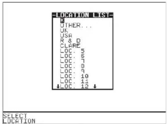
Location Name
Use the encoder to highlight a Location name and press Green to select the desired option. Select ‘*’ if you wish your search to include all of the names. Select ‘Other’ to search for a Location not in the list (this can happen if a Location name has been modified during testing). If you select ‘Other’ you are prompted to enter a location name. See Fig. 10.
User Name
Use the encoder to highlight a User name and press Green to select the desired option. Select 'All' if you wish your search to include all of the names. Select 'Other' to search for a User not in the list (this can happen if a User name has been modified during testing). If you select 'Other' you are prompted to enter a user name. See Fig.11.
Test Status
When Test Status is highlighted use the Green button to select the option required, each time you press Green a different option will be displayed. This can be PASS, FAIL or ‘*’ which indicates both.
Storage Status
When Storage Status is highlighted use the Green button to select the option required, each time you press Green a different option will be displayed. This can be NORMAL, DELETED or ‘ * ’ which indicates both.

Fig. 8

Fig. 9
When in Download data mode, do not search all by entering the character ‘ * ’ for all the six fields as this would download (print out) all the product results for all the parameters indicated. This will not stop until all printing has completed.
If you need to search and view the list of test results for reminder, exit from this Search for Download Data mode and use View Test Results at the Main menu before re-entering this mode for printing.
Date From
This option allows the user to search for test results after the selected date. Use the encoder to highlight the digit to be changed. Use the encoder to change the value. Select OK to store the settings or CANCEL to abort them.

Date To
This option allows the user to search for test results before the selected date. Use the encoder to highlight the digit to be changed. Use the encoder to change the value. Select OK to store the settings or CANCEL to abort them.

Search
After all the search parameters have been set, connect the appropriate printer or device. Press START SEARCH key or highlight START SEARCH & press GREEN to initiate search and download process.
If there are problems downloading e.g. due to interfacing problems, then after a short delay, the following error message appears: -
WARNING
PRINTER TIMEOUT: NO PRINTER CONNECTED PRESS START KEY TO CONTINUE
Press the red button to return to the search menu. On completion of successful downloading, the tester returns to the search for results menu. The user can then conduct on other search or press the red button to return to the main menu.
To print Barcode Pass/Fail Labels
In order to print barcode pass/fail labels the tests results required must be already stored in memory. Otherwise it is necessary to carry out an actual test first (see how to perform automatic tests). After a test is completed and the results stored in memory it is possible to download results to a thermal printer and print the pass/fail labels (see how to download results).
Note
Restrictions of paper width on certain printer means that Barcode representing more than 12 digits cannot be printed and a numbered label will be printed instead.
The print format options available are dependent upon the specific printer chosen. See Chapter 4 on Tips to configure the printer.
How to print Barcode Labels and Test codes
The Hal is capable of printing barcode labels in conjunction with a compatible thermal printer (see chapter 6 for Accessories).
To print barcode labels for User, Site, Location, Test code, Product & Test Type select Barcode Printing at Main menu and press Green to display the option list (Fig. 12). Highlight the desired option and press Green will bring up a selection list. Highlight option then press Print Barcode to print.

Fig. 12
To print barcode test codes
For example from the select test settings menu (Fig. 13) highlight the desired test e.g. DFLT AC HIPOT. Attach the compatible printer to the port and press PRINT BARCODE fast key on the display to initiate printing. A warning will be displayed if there is no printer connection or a connection problem has occurred (see Chapter 4 on Tips & Trouble Shooting).

To print barcode Product & Test Type
From the Barcode print menu select Product & Test Type, press Green to display the product & test type window. A default product number (representing 12 characters) will be shown in highlight. Press Green to enter the editor to Insert the correct product details (up to 15 characters). This option will just print out the barcode and number for the Product only when OK key is pressed. However to print Product number & Test type to be tested, enter details of product first as described then highlight Test type and press Green to display the test settings list. Highlight test type and press SELECT TEST and this displays the data selected as shown in Fig. 14. Notice that the Numbers of labels can also be selected for the printing process. Press OK key to confirm printing.

How to use Setup
To set up the Tester, use the cursor keys to highlight the Setup option on the Main Menu and press Green to display the following menu: -

From this menu you can change the way the Tester will operate and also change user levels and sites. Use the encoder to highlight a function and press Green to select the desired option.
Edit Test Settings
This allows the user to add, modify, remove or confirm test settings that can then be selected during automatic testing.
Also see Change Password.

Use the encoder to highlight a Test Setting and press Green to enter the Test Settings Editor: -
Test Settings Editor
The Test Settings Editor allows the test sequence for the selected test to be examined and changed if required: -.

Use the encoder to highlight a field to be changed and press Green to select the desired option. Use the fast key to highlight the desired field, and the encoder to cycle through the range of permissible values for the test parameter. Use the fast key to enter the value. To exit this editing phase, select the OK fast key. Changes will be stored to the system. These fields have been described in detail under the Default Test Settings section.
Name:
Each Sequence is given a name (this case DFLT AC HIPOT); this is to help the user when selecting Sequences during automatic testing. When Name is highlighted press Green, and then use the encoder to enter a new name for the Test Sequence (of up to 15 characters) and press Green again to confirm.
Test Parameter Fields
By selecting one of the test parameter fields from the Test Settings Editor, the encoder will cycle through all the available values for the test parameter.
Use the Green button to save the settings and return to the Test Settings Editor. Pressing Red will abort changes made to the settings and return to the Test Settings Editor.
Test codes
Use the encoder and Green button to select one of the Test code fields. A Test code can be entered manually or through a compatible barcode scanner, reader or wand (see How to use a Barcode Scanner).
Store Settings
Use the encoder to highlight the OK field and press Green to save the settings and return to the previous menu. Pressing Red will abort all of the changes made and return to the previous menu.
Print Test codes
The test codes can be printed using a compatible printer - See Chapter 6 for accessories.
Use the Green button to start the print. The following message will be displayed: -
PRINTING TESTCODES WORKING....
On completion of downloading, the system will return to the Test Settings Editor menu.
If there are problems downloading e.g. due to interfacing problems, then after a delay, the following error message appears: -
WARNING
PRINTER TIMEOUT: NO PRINTER CONNECTED PRESS START KEY TO CONTINUE
Press Red to return to the Test Settings Editor menu. Check if printer cable is connected or power to printer is turned on etc. Also ensure if the proper printer setup has been configured at System Configuration & Download Options menu. Then re-select the printing options and try again.
Edit User List / Options

Note
If you change the name of the user during testing all of the previous tests will still be referenced to the old user name; this gives unlimited amounts of users within memory.
Edit User Name
Select Setup from Main Menu. The setup screen will be displayed. Select User list using fast key or highlight Edit User List/Options and press Green to enter. Use the encoder to highlight a user name and press User settings fast key or press Green to select the desired option. You will be prompted to edit the current user settings. Highlight setting fields with cursor and press Green to enter editing. Insert fields as required using fast key. Then press Green followed by Red to accept new user name. Pressing Red during any changes will abort Edit mode.
The settings can be customized as follows for each user requirement.
Name
Highlight user name and press Green to enter field variables editor. Use the cursor key to highlight character and press Insert to select each desired option. Then press Green to accept changes.
User Level
Use the cursor key to highlight user level and press Green to select the desired option:
Novice - Selects the user level as a regular user. This provides an average level of help information and additional warnings and prompts.
Advanced - Selects the user level as an advanced user. This provides a minimum level of help information and additional warnings and prompts.
Startup Mode
Use the encoder to highlight a test mode on startup and press Green to select the desired option.
Main Menu (Automatic Mode)
The Tester will start up in Automatic Mode, with the Tester displaying the Main Menu.
Manual Mode
The Tester will start up in Manual Mode, with the Tester displaying the Manual Test Selection Menu.
Remote Mode
The tester will start in Remote Mode.
Beep on Key Press
Use the encoder to highlight a buzzer option and press Green to select the Yes/No option. If Yes is selected this option will beep each time a key is pressed.
Beep on Tests
Use the encoder to highlight a buzzer option and press Green to select the Yes/No option. If Yes is selected this option will beep whenever the High Voltage Test in progress icon is displayed or when a test has failed.
Beep on Barcodes
Use the encoder to highlight a buzzer option and press Green to select the Yes/No option. If Yes is selected this option will beep whenever a barcode has been received.
Beep on Warning
Use the encoder to highlight a buzzer option and press Green to select the Yes/No option. If Yes is selected this option will beep whenever a warning message is displayed to alert user.
Saving User Settings
After all changes have been made to the 'Edit User Settings' press OK fast key to save these user settings. Then press Red to move back to Setup screen.
Edit Site List

Note
If you change the name of the site during testing all of the previous tests will still be referenced to the old site name; this gives unlimited amounts of sites within memory.
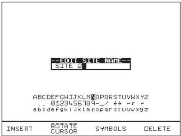
Edit Site Name
Select Setup from Main Menu. The setup screen will be displayed. Select Site list using fast key or highlight Edit Site List and press Green to enter. Use the encoder to highlight a site name and press Edit Name fast key or press Green to select the desired option. You will be prompted to edit the existing site name. Select data fields with cursor and press Insert key as required. Then press Green followed by Red to accept new site name. Pressing Red during any changes will abort Edit mode.
Edit Location List

If you change the name of the location during testing all of the previous tests will still be referenced to the old location name; this gives unlimited amounts of locations within memory.
Edit Location Name

Select Setup from Main Menu. The setup screen will be displayed. Select Edit Location List and press Green to enter. Use the encoder to highlight a location name and press Edit Name fast key or press Green to select the desired option. You will be prompted to edit the existing location name. Select data fields with cursor and press Insert key as required. Then press Green followed by Red to accept new location name. Pressing Red during any changes will abort Edit mode.
Change Date / Time
This option allows the user to change the Date and Time. Use Rotate Cursor (to select or deselect cursor tracking) and use encoder to move to desired fields for edition. Then select Rotate Field and use the encoder (to cycle through) to change the value of the field. Repeat above process until all fields have been changed. Select OK to store the new settings or press Red to cancel or abort changes. To update the new setting you must return to the MAIN MENU.

System Configuration
The Test Settings are included to cover the wide range of options that may be country or company specific.
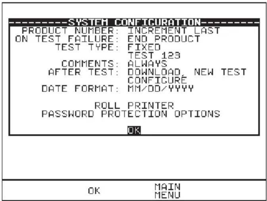
How to edit System Configuration
To edit any of the above fields, highlight a field to be changed, press Green (or press Green repeatedly for the options). When all fields have been satisfactorily selected press OK to store changes to memory.
Product Number: (Three options selectable)
- Increment Last
This option allows the tester to proceed to the next product ID (incremented by one) each time a test has completed.
- Repeat Last
This allows the test to be repeated on the previous product ID (same ID)
- Blank
This will bring up a blank Product ID after each test. The user will need to enter in any intended product ID again to proceed.
On Test Failure: (Two options)
- Failure Menu
This gives user the option of having a menu for a failure within an automatic test sequence. The menu will give user the option of retrying a failed test (Restart Test), revise Product detail (Restart Product), end the test (End Product) and aborting the test on the product (Abort Product).
- End Product
This will just end the test sequence immediately once Failure is detected.
Test Type: (Three options)
Any
This gives user the option of selecting from a test setting list each time before any test is instigated.
- Barcode only
This option allows user to scan in a Barcode representation of any test setting using a Barcode scanner.
• Fixed test Name (selected from test setting list e.g. Test 123)
This option allows user to keep to only one test setting for every test. To change to a different test setting, select Setup & System
Configuration and then highlight test Name, press Green. Select a new test Name from test setting list.
Otherwise select one of the two options above for more flexibility.
Comments:
- Never This will not allow any comments recording after each test.
• Always This will always allow user to enter comments after each test.
- On Pass This will allow user to enter comments only when a test has Passed.
- On Failure This will allow user to enter comments only when a test has Failed.
After Test:
- Menu (Options) This allows user to have the options to select New Test, Review test results, Download test results or return to Main Menu after each test.
- New Test This option allows user to progress to the ‘Next’ (new) product test.
However the ‘next’ product ID details displayed after each test will depend on the Product Number options selected. See product number options.
• Download, New Test
Configure – Highlight this to select Download Options (sends test results to a choice Printer, PC or Z-modem medium).
This will allow user to download the test results to any of the above options before proceeding to next test.
Date Format:
This allows user to select the date convention to be used (i.e. DD/MM/YYYY or MM/DD/YYYY)
Roll Printer: (REF 283A954)
This allows the user to define the thermal printer to be used with the Hal. Option selected must match with the printer connected especially for Barcodes printing. See Accessories at Main Menu.
Password Protection Options
This allows the user to password protect a list of selectable options. An existing password must be set-up before this option can be used. To select option highlight the field, press Green to effect 'lock or unlock' of password protection on the field options. Press OK to save format.

'Locked' field denotes that it will be password protected. Invoking any of those settings/options editor menu will required password to access.
'Unlocked' field denotes otherwise.
Change Password
It is possible to Password protect the Test Sequence Editor and the Country Settings.
If you currently do not have password protection you will be asked to enter a new password twice, once for confirmation.
If you currently do have password protection then you will be asked for the old password before entering a new one, again you will be asked for the new password twice.
To clear the password protection, simply press Enter when asked for the new password. A warning will show that no password is in place.
Set Brightness
You can now set the Brightness of the display. Use the encoder to change the Brightness, once the Brightness is set press the Green button to accept the changes. Press the Red button to abort any changes made.
Factory Settings
It is possible to reset the Hal to the settings that were configured from new. This option will first ask you if you are sure, select 'Yes' to reset or press CANCEL to Abort.
How to use the Memory
To use the memory tests and functions, use the encoder to highlight the Memory Options option on the Main Menu and press Green to display the following menu: -

Use the encoder to highlight a test or function and press Green to select the desired option.
View Memory Capacity
The Tester allows the user to see how much of the results memory is being used. The following bar graph of the memory remaining is displayed: -

Perform Memory Test
Once the, 'Perform memory test', option is highlighted press Green.
The memory test checks all of the Product results against their checksums. If the test result is a pass then no action is taken. If any tests fail then the Memory checksum requires updating. Use the encoder and press Green to choose an action if corrupted tests are found.
Note
The memory checksum is the sum of all of the memory excluding display data, registers and deleted tests.

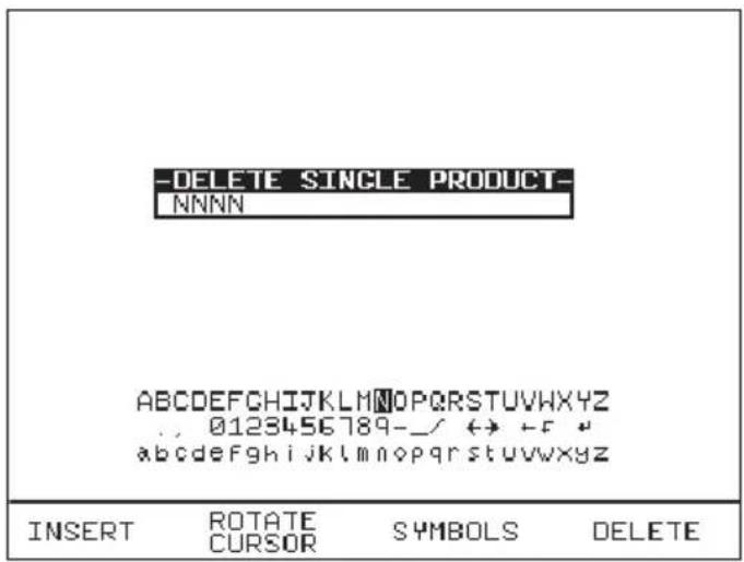
Delete Single Product
Enter the Product number to delete a single Product and press Green.
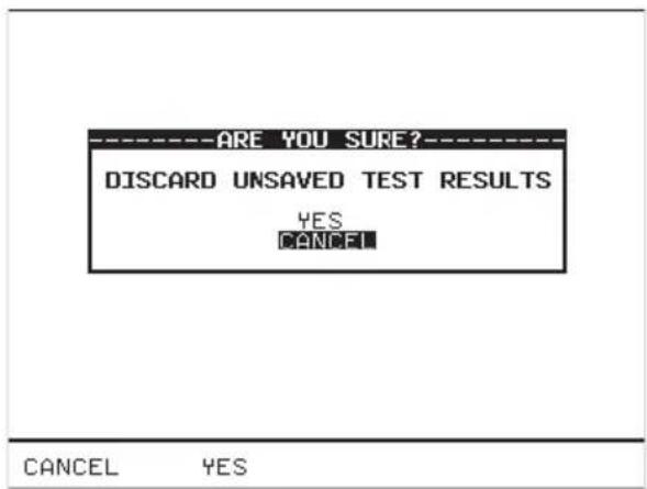
A warning 'Are You Sure?' prompt box will appear. Press CANCEL fast key to abort and return to the previous menu or press 'Yes' fast key to perform the delete operation and return to the previous menu.
Note:
Deleting Products in this way will delete all of the matched Products across all of the Sites and Locations.
When a single Product is deleted it is not removed from memory but hidden from the user. This test is still resident in memory and is taking up memory space, and this test can be reviewed / downloaded at a later date. Since the test is still resident in memory the View Memory Capacity figure may seem false. I.e. whilst you may think you have no results stored and the View Memory Capacity indicates there are results stored, previously deleted Products are resident in memory. In this situation to remove all resident tests select clear results memory.
Clear Results Memory
This option will delete (permanently) the entire test results of all Products tested and currently stored in memory and should be used with CAUTION!
A warning 'Are You Sure?' prompt will appear. Press the CANCEL (NO) fast key to return to the previous menu or press the YES fast key to perform the delete (Clearing) operation and return to the previous menu.
Note
It is recommended that the memory Results should be Downloaded to other retrievable form or format before embarking on clearing them from the system memory. This Deletion is Permanent.
To ensure unauthorized tempering this Option must always be password protected for access.
Clear Upload Memory
This option will delete all of the Product codes that have been uploaded from an external computer and should be used with CAUTION!
Note
Users will be asked whether they are sure about performing this action.
A warning 'Are You Sure?' prompt will appear. Press the CANCEL fast key to return to the previous menu or press the YES fast key to perform the delete operation and return to the previous menu.
How to Change User Name
At the Main Menu screen select Change User and press Green (or press Change User fast key). Use the encoder to highlight a user name and press Select User fast key or press Green to select desired option. Selected option will be automatically updated. For a user not found in list, select New from list and you will be prompted to enter name of the new user. Press Insert to accept each data field entered and then press green button to accept new User name. The total number of users available in list is 20.

Edit User Name
To edit User name see sections on How to use Setup & Edit User list.
How to Change Site Name
At the Main Menu screen select Change Site and press Green. Use the encoder to highlight a site name and press Select Site fast key or press Green to select desired site. Selected option will be automatically updated. For a site not found in list, select New from list and you will be prompted to enter name of the new site. Press Insert to accept each data field entered and press Green to accept 'New' site name. The total number of sites available in list is 20.

Edit Site Name
To edit Site name see sections on How to use Setup & Edit Site list.
How to Change Location Name
At the Main Menu screen select Change Location and press Green. Use the encoder to highlight a location name and press Select Location fast key or press Green to accept desired location. Selected option will be automatically updated. For a location not found in list, select New from list and you will be prompted to enter name of the new location. Press Insert to accept each data field entered and press green to accept 'New' location name. The total number of locations available in list is 50.
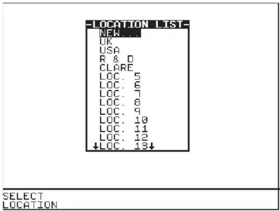
To edit Location name see sections on How to use Setup & Edit Location list.
How to use Help
The Tester is provided with an on-line help function, which can be called up at during the test screens by pressing the Help fast key.
Each test will have three or four help pages depending on connection information.
Help provided to the User
The Help function provides the following information: -
Description of Test
The first help page shown contains information on the particular test, including its icon and a description of the purpose of the test.
How to Perform Tests
The second page of information describes how the Tester performs the test. A diagram showing how to connect the Tester to the EUT is included. An example for the Insulation test is shown below: -

A description of how to connect the test leads and perform the test is provided in a step-by-step format.
Note:
This topic will cover one or two pages depending on the connection options available (Insulation and Hipot can be Class 1 or Class 2). Each connection option will have a new page of information.
Why tests fail
The final page of information provides guidance on why a test may fail e.g. connection problems. This includes a step by step checklist to ensure all of the connections are correct and secure.
The effect of User Levels during Test Sequences
There are two possible user levels: Novice and Advanced.
Note
The user level for a new user is set to Novice.
Novice User Level
When the user level is set to Novice Level, the help information is displayed before every new test
Press the Green button key to continue the sequence.
Advanced User Level
When the user level is set to 'Advanced Level', no help information will be shown before a test. Use the Help/Information key for help information if required at any time.
Chapter 4 Tips & Troubleshooting
Power -On Self tests:
When the tester is powered on, a number of messages can possibly appear as the tester performs safety tests on itself and the mains power supply.
Temperature monitoring
The tester is provided with temperature monitoring facilities to ensure that prolonged tests do not overheat sensitive components. If, during testing a ‘Over temperature’ warning is displayed, switch off any EUT, and allow the tester to cool. This is provided to allow the EUT to be switched off in a controlled way.
Barcodes
Barcode Scanner Specification
The Hal Tester can be used with barcodes and barcode scanners, readers or wands. These connect to the serial (RS232) connector. The required configuration is as follows: -
Baud Rate: 9600
Start Bits: 2
Data Bits 8
Stop Bits: 2 (1 Combi)
Parity: None
Inter-character Delay: 20ms
When to use a Barcode Scanner
Barcodes can be scanned at the following points: -
- Entering a Test code as part of an Automatic Test or Test Setting Editor
- Selecting Test type
- Entering Product number, changing User, Site or Location
- Entering Comments and where text is needed.
Interfacing
The Tester provides three interfacing ports: -
For connection to a PC, printer or Barcode Reader
To avoid any problems during download, ensure that leads are undamaged and correctly wired.
The Connector pin-outs for Serial ports are shown below: -
Parallel - The Hal range features a serial port. However a serial to parallel adapter is available to allow interface with parallel ports. See accessories in Chapter 6.
Downloading to Computer Software
Serial Port
The serial port uses a standard 9-way D-type connector

| Pin | Description |
| 1. | N.C. |
| 2. | RX |
| 3. | TX |
| 4. | DTR |
| 5. | 0V |
| 6. | N.C. |
| 7. | 0V |
| 8. | N.C. |
| 9. | +5V |
Baud Rate: 9600, 19200, 28800 (selectable)
Start Bits: 2
Data Bits 8
Stop Bits: 1 (2 Scan)
Parity: None
Flow-control Xon/Xoff (not on Scan)
Inter-character Delay: 20ms
Chapter 5 Maintaining the Tester
Cleaning the Tester
The Tester case can be cleaned with a damp cloth, with if necessary, a small amount of mild detergent. Prevent excessive moisture around the socket panel or in the lead storage area.
Do not allow liquid inside the Tester, or near the socket panel. Do not use abrasives, solvents, or alcohol.
If any liquid is spilt into the Tester case, the Tester should be returned for repair, stating the cause of the defect.
User Maintenance
The Tester is a rugged quality instrument. However, care should always be taken when using, transporting and storing this type of equipment. Failure to treat the product with care will reduce both the life of the instrument its reliability.
If the Tester is subject to condensation, allow the Tester too completely dry before use.
- Always check the Tester and all test leads for signs of damage and wear before use.
- Do not open the Tester under any circumstances.
- Keep the instrument clean and dry.
- Avoid testing in conditions of high electrostatic or electromagnetic fields.
- Maintenance should only be performed by authorized personnel.
• There are no user replaceable parts in the Tester.
• The unit should be regularly calibrated (at least annually).
For Service and calibration contact:-
Service Dept.,
Seaward Group.
Unit 11
Bracken Hill
South West Industrial Estate
Peterlee
Co. Durham
SR8 2LS
England
Tel: +44 (0)191 587 8739
Fax: +44 (0)191 587 8737
E-mail: service@seaward.co.uk
Chapter 6 Accessories
Standard Accessories
| Accessory | Part | H101 | H102 | H103 | H104 | HLED |
| IEC Mains Lead (U.K.) | 39044 | 1 | 1 | 1 | ||
| 13A Mains Lead (U.K.) | 48319 | 1 | 1 | |||
| IEC Mains Lead (U.S.A) | 44B118 | 1 | 1 | |||
| 20A Mains Lead (U.S.A) | 48327 | 1 | 1 | |||
| IEC Mains Lead (Euro) | 48230 | 1 | ||||
| 16A Mains Lead (Euro) | 48341 | 1 | 1 | |||
| No Burn Ground Bond Probe | 01520/1 | 1 | 1 | 1 | ||
| Hipot Probe | 03919/2 | 1 | 1 | 1 | ||
| Hipot Clip & Lead | H-5003 | 1 | 1 | 1 | ||
| Guard Plug | CON965/L | 1 | 1 | 1 | 1 | 1 |
| Accessory | Part Number |
| Output Box (U.K.) H103 | G2-5001 |
| Output Box (E.U.) H103 | G2-5002 |
| Output Box (USA) H103 | G2-5003 |
| Output Box (U.K.) H104/HLED | 477A675 |
| Output Box (E.U.) H104/HLED | 477A676 |
| Output Box (USA) H104/HLED | 477A679 |
Optional Accessories
| Accessory | Part Number |
| Hipot Probe + lead | 03918/2 |
| Ground Bond Clip Lead | 01521/1 |
| Hand Held Guard Switch | DCS317 |
| CCD Barcode Scanner | 194A922 |
| Desk Test n Tag Printer | 312A916 |
| Product Number Labels (250) | 194A307 |
| Test Code Labels (240) | 194A308 |
| Serial to Parallel adapter | 270A954 |
| Serial-PC Download Lead (9-9 way) | H-5014 |
| Serial-PC Download Lead (9-25way) | 194A920 |
| Pass Labels (500) | 91B038 |
| Desk T n T Labels (Orange) | 312A954 |
| Desk T n T Labels (White) | 312A951 |
| Desk T n T Labels (Yellow) | 312A956 |
| Desk T n T Labels (Blue) | 312A957 |
| Desk T n T Labels (Red) | 312A961 |
| Desk T n T Labels (Green) | 312A962 |
| Desk T n T Ribbon | 312A952 |
| Status Beacon (mains cord 230/110V) | H - 5017 |
| Desk T n T Labels Small (White) | 312A972 |
| Safety E-Base Software | 482A910 |
Chapter 7 Specifications
Input Rating
Supply Voltage selectable 115V/230V a.c. RMS
Frequency 50/60 Hz
Fuse 3A 250V H101 & H102
5A 250V H103
2 x 4A 250V, 2 x F16A HRC 300V, 2 x 20A HRC 300V H104
Display
Type 14 VGA Monochrome Graphical
Environmental Specifications
| Operating Temperature | 0°C to +45 °C |
| Storage Temperature | -20°C to +60 °C |
| Humidity | Non Condensing (<10°C) 95% |
| RH | |
| Dust/Water Resistance | Min IP40 |
Mechanical Specification
| Size (HxWxL) | 300mm-200mm-370mm |
| Weight | 15kg Approx |
Safety Specifications
| Electrical Safety | CAT II 300V, |
| Pollution Degree II |
Earth / Ground Bond Test (H103/H104/HLED)
| Test Voltage | Nominal 6V AC |
| Frequency Independent of Supply | 50 or 60 Hz) |
| Display Range and Accuracy | 0-1500mΩ ±2% ±5 Counts |
| Display Resolution | 1 mΩ |
| Compliance Test Ranges | |
| Current/Time* | 4A - 110 secs |
| 25A - 60 secs | |
| 40A - 30 secs |
*Test Duration limited Pro-Rata between 4A and 40A
| Settable Output Current Range | 0.1A – 40.0A |
| Selectable Pass/Fail Levels | 0-1500 mΩ |
Remote Test Initiation – via No-Burn Ground Bond Probe
Insulation Test (All Models)
| DC Output Voltage | 250V, 500, or 1000V Selectable when set to limited, 100V-6kV when set to unlimited |
| Display Range | 0.01MΩ-500MΩ |
| Display Range / Accuracy | 0.03MΩ - 350 MΩ ± 5% ± 5 Counts350MΩ -500 MΩ Indication Only |
| Display Resolution | 0.01MΩ |
| Pass/Fail Level | 0.00MΩ-500.0MΩ |
AC HiPot Test (All Models)
| Programmable Voltage Range | 0.10 kV-5.00 kV (10V/Step) |
| Frequency Independent of Supply | 50 or 60 Hz |
| Voltage Display and Accuracy | 0.10 kV-5.00kV ±1% ± 5 Counts |
| Voltage Display Resolution | 0.01kV |
| Current Display and Accuracy | 0.01mA-20.00mA ±1% ± 5 Counts |
| Current Display Resolution | 0.01mA |
| Selectable Range of Pass/Fail Levels* | 0.01mA-20.00mA |
| Maximum Current Output | 20.00mA @5kV |
| Optional Arc Detection | 9 Levels |
DC HiPot Test (All Models)
| Programmable Voltage Range | 0.10 kV-6.00 kV (10V/Step) |
| Voltage Display and Accuracy | 0.10 kV-6.00kV ±1% ± 5 Counts |
| Voltage Display Resolution | 0.01kV |
| Current Display R and Accuracy | 0.01mA-10.00mA ±1% ± 5 Counts |
| Current Display Resolution | 0.01mA |
| Selectable Range of Pass/Fail Levels* | 0.01mA-10.00mA |
| Maximum Current Output | 10.00mA |
| Optional Arc Detection | 9 Levels |
* Full selectable range only achievable with the use of Safety Base, excluding HAL102
Powered Leakage Tests (H104/HLED)
Power Output Rating
Test Voltage
110V - 230V AC 20A nominal (Vin-Vout)
Maximum Power Output
Up to 5.0kVA (dependant on mains supply rating)
Output Power Measurement (H104)
Single Phase Power Measurement
Display Range and Accuracy 0.020kVA-5.000kVA ±2% ±0.020kVA
Selectable Range of Pass/Fail Levels 0.001kVA-5.000kVA
Output Power Measurement (HLED)
Display Range and Accuracy 000.0VA - 99.9VA ± 5% ±5 digits
100.0VA - 999.9VA ± 5% ±2 digits
Selectable Range of Pass/Fail Levels 000.2 - 999.9VA
Single Phase Power Factor Measurement
Display Range 0.000 - 1.000*
Selectable Range of Pass/Fail Levels 0.000 - 1.000
*Note: Displayed value for Indication Only
Leakage Current Measurement
Display Range and Accuracy 0.10mA-20.00 mA ± 1% ±5 Counts
Display Resolution 0.01mA
Selectable Range of Pass/Fail Levels 0.01mA-20mA
Touch Current Measurement
Display Range and Accuracy 0.02mA - 5.00 mA ± 1% ±5 Counts
Display Resolution 0.01
Selectable Range of Pass/Fail Levels 0.02mA-5.00mA
Measuring Device
IEC/EN 60990 Fig 4
(IEC/EN 60990 Fig 3 or Fig 5 Upon Request)
Mechanical
| Size | 370mm x 300mm x 204mm |
| Weight | 15kg |
Environmental
| Operating | 0°C to 40°C (non condensing) |
| Storage | -10°C to 50°C (non condensing) |
| Maximum R.H | 90% |
| Protection Level | CAT II 300V |
Appendix A Purpose of Tests

Do not exceed 3750V AC, or 4280V DC when performing Hipot or Insulation tests with rear test output
Insulation Test

1000V, 500 V, and 250 V D.C. test voltage
This test is used to verify that adequate insulation exists between the mains supply pins and earth.
During the insulation test, a HV DC voltage is applied between the earth pin and both the live and neutral pins of the Product mains supply plug. The Tester displays the resistance measured and allows the user to confirm sufficient insulation exists.
For a product that incorporates over-voltage protection, a 250V DC test voltage is provided to allow a reading to be taken without the protection devices generating a false failure.
Hipot Test

5000V a.c./6000V d.c. Test voltage
This test is used to determine that the insulation is of sufficient strength to prevent breakdown, particularly where high transient voltages are likely. This test can be omitted when testing equipment with components whose voltage withstands rating is insufficient to accommodate the test without damage. This is especially true of IT equipment.
For Class I Products, a nominal test voltage of 1.5kV AC RMS is applied between the earth pin, and both the live and neutral pins of the Product mains supply plug
For Class II Products, a nominal voltage of 3kV AC RMS is applied between the Hipot probe tip and the live and neutral pins of the Product mains supply plug.
Ground (Earth) Bond Test

Caution
6V (no-load) 0-40A AC test Current
This test is to ensure that the connection between the earth pin in the mains plug of the appliance and the metal casing of the appliance is satisfactory and of sufficiently low resistance. This test is usually done on Class 1 (Metal Case) products only.
During the test, an AC voltage and the test current is applied between the earth pin of the mains supply plug and the ground (earth) bond test lead clip/probe. The test output box must be used for connection to the EUT for this test. When a ground bond test probe (optional item) is used the special (shorted) guard switch plug provided should be used in combination to free user of pressing the guard switch during the test.
A high current is normally used to stress the connection under fault conditions. The length of the test should be limited to prevent damage due to overheating. Tests currents of up to 40A AC are available from this tester. The test output currents, and set resistance HI/LO values limits are fully programmable. The test duration will be limited dependent upon the test current selected. The Tester measures the test values using a 4-wire measurement method then displays the resistance measured and allows the user to confirm that sufficiently low resistance exists within the EUT protective bonding path.

Caution
Prolonged use of the ground bond probe at high currents can lead to a high probe temperature. Care should be taken to avoid touching the probe tip under these conditions. The Tester's Internal over temperature switch may operate with prolonged repetitive use of high test currents. In this instance an error message will be displayed. In order to proceed with further tests the Tester must be allowed to cool down.
Powered Load and Leakage Test

Caution
The Powered Leakage tests provide four main measurements:-
1 - Power Measurement
This is the power drawn when the EUT is supplied with the nominal MAINS voltage.
2 - Power Factor
Power factor is often used to ensure that products using motors have been constructed correctly and that there is no likelihood that moving parts such as motor bearings have been damages or seated incorrectly.
3 – Earth Leakage (Protective Conductor Current)
Protective conductor current is a measure of the current that is flowing to earth from the EUT.
4 – Touch Leakage (Touch Current)
Touch Current is a measure of the current that would flow through the human body if a person was to touch the EUT whilst it is in operation. The Ground / Earth Bond probe is used to provide a path to Earth via the internal body model measuring device.
Appendix B Reference
Factory-set Test Sequences
-
Name - Default AC Hipot Rise Time - 2.0 s Hold Time - 10 s Fall Time - 2.0 s Output Voltage - 2.5 kV a.c. Low Trip Level - 7.0 mA High Trip Level - 10.0 mA Arc Detection Setting - Level 5 Number of Tests - 1 Start Conditions - External Guard + START Button
-
Name - Default DC Hipot Rise Time - 2.0 s Hold Time - 2.0 s Fall Time - 2.0 s Output Voltage - 0.5 kV d.c. Low Trip Level - 7.0 mA High Trip Level - 10.0 mA Arc Detection Setting - Level 5 Number of Tests - 1 Start Conditions - External Guard + START Button
Test code Tables
Seaward Test codes are an 11-character string where each character is in the ASCII range '0' to '9' and 'A' to 'Z'. The character count starts from left to right. The example below shows Z as digit 1 or (character no. 1) and the integer 1 as digit 2 (character no. 2) and so on.
e.g. Z1234567890
Digit 1 (Character 1) – Test code Type
Digit 1 associates the test code with Seaward Group Ltd. Equipment
| Digit 1 : Test code Type | |
| ‘Z’ | Seaward Group Ltd. Test code |
Digit 2 – Test Type
Digit 2 represents the type of test to be performed. On the H102 it also encodes the status of H102 channel 1 – only relevant if the test code is at the top of a loop. If no channels are explicitly encoded for use then channel 1 will be used.
H101
| Digit 2 : Test Type | |
| ‘0’ | Skip Test |
| ‘1’ | AC Hipot 50Hz |
| ‘2’ | AC Hipot 60Hz |
| ‘3’ | DC Hipot |
| ‘4’ | DC Insulation Resistance |
| ‘5’ – ‘9’ | Not Used |
| ‘A’ – ‘Z’ | Not Used |
H102
| Digit 2 : Test Type | ||
| H102 Channel 1 | ||
| Test Type | Use Channel 1 | Do Not Use Channel 1 |
| Skip | ‘0’ | ‘G’ |
| AC Hipot 50Hz | ‘1’ | ‘H’ |
| AC Hipot 60Hz | ‘2’ | ‘I’ |
| DC Hipot | ‘3’ | ‘J’ |
| DC IR | ‘4’ | ‘K’ |
| Spares (respectively) | ‘5, 6, 7, 8 & 9’ | ‘L, M, N, O & P’ |
| Spares (respectively) | ‘A, B, C, D, E & F’ | ‘Q, R, S, T, U & V’ |
H103
| Digit 2 : Test Type | |
| ‘0’ | Skip Test |
| ‘1’ | AC Hipot 50Hz |
| ‘2’ | AC Hipot 60Hz |
| ‘3’ | DC Hipot |
| ‘4’ | DC Insulation Resistance, DC IR |
| ‘5’ | EBond 50Hz |
| ‘6’ | EBond 60Hz |
| ‘7’ – ‘9’ | Not Used |
| ‘A’ – ‘Z’ | Not Used |
HAL104
| C0 | C1 | Notes | ||
| Test Type | Skip | ‘0’ | ‘G’ | |
| AC HIPOT 50Hz | ‘1’ | ‘H’ | ||
| AC HIPOT 60Hz | ‘2’ | ‘I’ | ||
| DC HIPOT | ‘3’ | ‘J’ | ||
| DC IR | ‘4’ | ‘K’ | ||
| EBOND 50Hz | ‘5’ | ‘L’ | ||
| EBOND 60Hz | ‘6’ | ‘M’ | ||
| Power + Leakage | ‘7’ | ‘N’ | ||
| Power + Touch Leakage | ‘8’ | ‘O’ | ||
| Spare | ‘9’ | ‘P’ | ||
| Spare | ‘A’ | ‘Q’ | ||
| Spare | ‘B’ | ‘R’ | ||
| Spare | ‘C’ | ‘S’ | ||
| Spare | ‘D’ | ‘T’ | ||
| Spare | ‘E’ | ‘U’ | ||
| Spare | ‘F’ | ‘V’ | ||
Digit 3 – Start Conditions & Base Target Voltage
Digit 3 is a combination of the start conditions for the test and the base target voltage (to which the value encoded in digit 4 is added).
| Digit 3 | ||||||
| Base Target Voltage | ||||||
| C0 | C1 | C2 | C3 | C4 | ||
| 0.0kV | 1.6kV | 3.2kV | 4.8kV | |||
| Start Conditions | Ext. guard switch opened then closed followed by START button (all loops) | ‘0’ | ‘7’ | ‘E’ | ‘L’ | ‘S’ |
| Ext. guard switch opened then closed followed by START button (first loop) | ‘1’ | ‘8’ | ‘F’ | ‘M’ | ‘T’ | |
| Ext. guard switch opened then closed (all loops) | ‘2’ | ‘9’ | ‘G’ | ‘N’ | ‘U’ | |
| Ext. guard switch opened then closed (first loop) | ‘3’ | ‘A’ | ‘H’ | ‘O’ | ‘V’ | |
| START button (all loops) | ‘4’ | ‘B’ | ‘I’ | ‘P’ | ‘W’ | |
| START button (first loop) | ‘5’ | ‘C’ | ‘J’ | ‘Q’ | ‘X’ | |
| None (test starts without any activity on ext. guard switch or START button) | ‘6’ | ‘D’ | ‘K’ | ‘R’ | ‘Y’ | |
Note that no test will be started unless the guard switch is closed, and any test in progress is automatically and immediately terminated if the guard switch is opened during a test. Where the external guard switch appears as part of the start conditions it implies that the GUI will wait for the guard switch to be open for 150ms and then remain closed for at least 150ms before the test will be started (or before the START key will be enabled, if required).
For EBOND and PWR tests the probe's micro-switch acts in parallel to the START button. The micro-switch must be open for at least 120ms after any required guard switch activity is complete, and then remain closed for 90ms before a test will be started.
For HV tests digit 3 also specifies part of the target voltage. Columns C0, C1, C2, and C3 represent 0.00 kV, 1.60 kV, 3.20 kV, and 4.80 kV respectively. Characters in column C4 are not permitted.
For EBOND tests only characters in column C0 are permitted.
For PWR tests digit 3 also specifies part of the loops index value.
Characters in columns C0, C1, C2, C3, and C4 add 0, 1, 2, 3, 4
respectively to the loops index value. See the explanation of digit 11 for HI-POT and EBOND tests for the settings applicable to each loop index and an explanation of loop functionality.
Digit 4 – Target Voltage Offset
Digit 4 represents the output voltage offset to be added to the base target voltage. The target voltage is achieved at the end of the ‘Ramp to Target’ time and is maintained during the ‘Hold’ time. During VARIABLE Tests (digit 5 = ‘Z’ the target voltage is used as the maximum possible output voltage, helping prevent damaging or dangerous voltages being applied to the device under test.
Note that not all combinations of ‘Base Target Voltage’ and ‘Target Offset Voltage’ are Valid. AC Hipot Tests have a 0.1 - 5.00kV range, while DC Hipot tests have a 0.1 - 6.00kV range and DC IR Tests have discrete output voltages of 0.25kV, 0.5kV and 1.0 kV.
The Tester's test code editor will not generate invalid combinations and all invalid entry or invalid scanned test codes will be rejected.
A 0.00kV output voltage is intended to be used as a 'rest' period between other tests in a sequence. Such sequences may be linked or repeated (See digit 11).
H101 & H102
| Digit 4 : Target Voltage Offset | |
| ‘0’ | 0.00kV |
| ‘1’ | 0.05kV |
| ‘2’ | 0.10kV |
| ‘3’ | 0.15kV |
| ‘4’ | 0.20kV |
| ‘5’ | 0.25kV |
| ‘6’ | 0.30kV |
| ‘7’ | 0.35kV |
| ‘8’ | 0.40kV |
| ‘9’ | 0.45kV |
| ‘A’ | 0.50kV |
| ‘B’ | 0.55kV |
| ‘C’ | 0.60kV |
| ‘D’ | 0.65kV |
| ‘E’ | 0.70kV |
| ‘F’ | 0.75kV |
| ‘G’ | 0.80kV |
| ‘H’ | 0.85kV |
| ‘I’ | 0.90kV |
| ‘J’ | 0.95kV |
| ‘K’ | 1.00kV |
| ‘L’ | 1.05kV |
| ‘M’ | 1.10kV |
| ‘N’ | 1.15kV |
| ‘O’ | 1.20kV |
| ‘P’ | 1.25kV |
| ‘Q’ | 1.30kV |
| ‘R’ | 1.35kV |
| ‘S’ | 1.40kV |
| ‘T’ | 1.45kV |
| ‘U’ | 1.50kV |
| ‘V’ | 1.55kV |
H103
| Digit 4 : HV TestTarget Voltage Offset | Digit 4 : EBOND TestCurrent Level | |
| ‘0’ | 0.00kV | 0.0A |
| ‘1’ | 0.05kV | 0.1A |
| ‘2’ | 0.10kV | 0.2A |
| ‘3’ | 0.15kV | 0.3A |
| ‘4’ | 0.20kV | 0.4A |
| ‘5’ | 0.25kV | 0.5A |
| ‘6’ | 0.30kV | 0.6A |
| ‘7’ | 0.35kV | 0.7A |
| ‘8’ | 0.40kV | 0.8A |
| ‘9’ | 0.45kV | 0.9A |
| ‘A’ | 0.50kV | 1.0A |
| ‘B’ | 0.55kV | 1.5A |
| ‘C’ | 0.60kV | 2.0A |
| ‘D’ | 0.65kV | 2.5A |
| ‘E’ | 0.70kV | 3.0A |
| ‘F’ | 0.75kV | 3.5A |
| ‘G’ | 0.80kV | 4.0A |
| ‘H’ | 0.85kV | 4.5A |
| ‘I’ | 0.90kV | 5.0A |
| ‘J’ | 0.95kV | 6.0A |
| ‘K’ | 1.00kV | 7.0A |
| ‘L’ | 1.05kV | 8.0A |
| ‘M’ | 1.10kV | 9.0A |
| ‘N’ | 1.15kV | 10.0A |
| ‘O’ | 1.20kV | 12.5A |
| ‘P’ | 1.25kV | 15.0A |
| ‘Q’ | 1.30kV | 17.5A |
| ‘R’ | 1.35kV | 20.0A |
| ‘S’ | 1.40kV | 22.5A |
| ‘T’ | 1.45kV | 25.0A |
| ‘U’ | 1.50kV | 27.5A |
| ‘V’ | 1.55kV | 30.0A |
| ‘W’ | N/A | 32.5A |
| ‘X’ | N/A | 35.0A |
| ‘Y’ | N/A | 37.5A |
| ‘Z’ | N/A | 40.0A |
Digit 5 – Ramp to Target Time
Digit 6 – Hold Time
Digit 7 – Ramp to Zero Time
Digits 5, 6 and 7 represent times during which the out voltage is ramped to the target voltage, held at the target voltage and finally ramped down to zero. All the times are in seconds.
*Digit 4 is also used in conjunction with Powered Leakage tests to define the test duration.
| Digit 5 Ramp to Target Time | Digit 6 (4)* Hold Time | Digit 7 Ramp to Zero Time | |
| ‘0’ | 0.0 | 0.0 | 0.0 |
| ‘1’ | 0.1 | 0.1 | 0.1 |
| ‘2’ | 0.2 | 0.2 | 0.2 |
| ‘3’ | 0.3 | 0.3 | 0.3 |
| ‘4’ | 0.4 | 0.4 | 0.4 |
| ‘5’ | 0.5 | 0.5 | 0.5 |
| ‘6’ | 0.6 | 0.6 | 0.6 |
| ‘7’ | 0.7 | 0.7 | 0.7 |
| ‘8’ | 0.8 | 0.8 | 0.8 |
| ‘9’ | 0.9 | 0.9 | 0.9 |
| ‘A’ | 1.0 | 1.0 | 1.0 |
| ‘B’ | 1.5 | 1.5 | 1.5 |
| ‘C’ | 2.0 | 2.0 | 2.0 |
| ‘D’ | 3.0 | 3.0 | 3.0 |
| ‘E’ | 4.0 | 4.0 | 4.0 |
| ‘F’ | 5.0 | 5.0 | 5.0 |
| ‘G’ | 7.5 | 7.5 | 7.5 |
| ‘H’ | 10.0 | 10.0 | 10.0 |
| ‘I’ | 15.0 | 15.0 | 15.0 |
| ‘J’ | 20.0 | 20.0 | 20.0 |
| ‘K’ | 30.0 | 30.0 | 30.0 |
| ‘L’ | 45.0 | 45.0 | 45.0 |
| ‘M’ | 60.0 | 60.0 | 60.0 |
| ‘N’ | 90.0 | 90.0 | 90.0 |
| ‘O’ | 120.0 | 120.0 | 120.0 |
| ‘P’ | 150.0 | 150.0 | 150.0 |
| ‘Q’ | 180.0 | 180.0 | 180.0 |
| ‘R’ | 240.0 | 240.0 | 240.0 |
| ‘S’ | 300.0 | 300.0 | 300.0 |
| ‘T’ – ‘Y’ | Not Used | Not Used | Not Used |
| ‘Z’ | Specifies the output voltage is VARIABLE up to the target voltage using the rotary encoder. Initial value is 0.00kV, digit 6 is ignored whilst digit 7 is acted upon once user ends the variable voltage phase (by pressing the Start button). | Specifies an infinite duration hold time, until the test is terminated. | The current output voltage is used as the start value for the next ‘ramp to target’ at the beginning of the next test.“ Maintained “ |
Digit 8 – Lower Trip Limit (H103 – AC/DC Hipot & DC IR)
Digit 9 – Upper Trip Limit (H103 – AC/DC Hipot & DC IR)
Digits 8 and 9 represent the lower and upper trip limits respectively.
| D 8 | D 9 | D 8 | D 9 | D 8 | D 9 | ||||
| AC Hipot | DC Hipot | DC IR | |||||||
| Lo | Hi | Lo | Hi | Lo | Hi | ||||
| ‘0’ | X | N/A | X | N/A | N/A | X | |||
| ‘1’ | 0.10mA | 0.10mA | 1.00MΩ | ||||||
| ‘2’ | 0.20mA | 0.20mA | 1.25MΩ | ||||||
| ‘3’ | 0.30mA | 0.30mA | 1.50MΩ | ||||||
| ‘4’ | 0.40mA | 0.40mA | 1.75MΩ | ||||||
| ‘5’ | 0.50mA | 0.50mA | 2.00MΩ | ||||||
| ‘6’ | 0.75mA | 0.75mA | 2.25MΩ | ||||||
| ‘7’ | 1.00mA | 1.00mA | 2.50MΩ | ||||||
| ‘8’ | 1.25mA | 1.25mA | 2.75MΩ | ||||||
| ‘9’ | 1.50mA | 1.50mA | 3.0MΩ | ||||||
| ‘A’ | 1.75mA | 1.75mA | 3.5MΩ | ||||||
| ‘B’ | 2.00mA | 2.00mA | 4.0MΩ | ||||||
| ‘C’ | 2.25mA | 2.25mA | 4.5MΩ | ||||||
| ‘D’ | 2.50mA | 2.50mA | 5.0MΩ | ||||||
| ‘E’ | 2.75mA | 2.75mA | 5.5MΩ | ||||||
| ‘F’ | 3.00mA | 3.00mA | 6.0MΩ | ||||||
| ‘G’ | 3.50mA | 3.50mA | 6.5MΩ | ||||||
| ‘H’ | 4.00mA | 4.00mA | 7.0MΩ | ||||||
| ‘I’ | 4.50mA | 4.50mA | 7.5MΩ | ||||||
| ‘J’ | 5.00mA | 5.00mA | 8.0MΩ | ||||||
| ‘K’ | 6.00mA | 6.00mA | 9.0MΩ | ||||||
| ‘L’ | 7.00mA | 7.00mA | 10.0MΩ | ||||||
| ‘M’ | 8.00mA | 8.00mA | 12.5MΩ | ||||||
| ‘N’ | 9.00mA | 9.00mA | 15MΩ | ||||||
| ‘O’ | 10.00mA | 10.00mA | 20MΩ | ||||||
| ‘P’ | 12.50mA | N/A | 30MΩ | ||||||
| ‘Q’ | 15.00mA | N/A | 40MΩ | ||||||
| ‘R’ | 17.50mA | N/A | 50MΩ | ||||||
| ‘S’ | 20.00mA | N/A | 75MΩ | ||||||
| ‘T’ | N/A | N/A | 100MΩ | ||||||
| ‘U’ | N/A | N/A | 200MΩ | ||||||
| ‘V’ | N/A | N/A | 500MΩ | ||||||
| ‘W’ | N/A | N/A | 750MΩ | ||||||
| ‘X’ | N/A | N/A | 1000MΩ | ||||||
H103
Digit 8 – Lower Trip Limit (Ebond)
Digit 9 – Upper Trip Limit (Ebond)
Digit 10 – Lower/Upper Limit (Ebond)
Digits 8, 9, and 10 are used to encode the indices into a lookup table of earth bond limits for the lower limit and the higher limit. By encoding digits 8, 9, and 10 according to the following table, it is possible to generate independent lookup table indices for the lower and higher limits between 0 and 215.
| Digit 8 | Digit 9 | Digit 10 | |||
| Table Index for LO Limit | Table Index for HI Limit | Table Index for LO Limit | Table Index for HI Limit | ||
| ‘0’ | +0 | +0 | +0 | +0 | |
| ‘1’ | +1 | +1 | +36 | +0 | |
| ‘2’ | +2 | +2 | +72 | +0 | |
| ‘3’ | +3 | +3 | +108 | +0 | |
| ‘4’ | +4 | +4 | +144 | +0 | |
| ‘5’ | +5 | +5 | +180 | +0 | |
| ‘6’ | +6 | +6 | +0 | +36 | |
| ‘7’ | +7 | +7 | +36 | +36 | |
| ‘8’ | +8 | +8 | +72 | +36 | |
| ‘9’ | +9 | +9 | +108 | +36 | |
| ‘A’ | +10 | +10 | +144 | +36 | |
| ‘B’ | +11 | +11 | +180 | +36 | |
| ‘C’ | +12 | +12 | +0 | +72 | |
| ‘D’ | +13 | +13 | +36 | +72 | |
| ‘E’ | +14 | +14 | +72 | +72 | |
| ‘F’ | +15 | +15 | +108 | +72 | ||
| ‘G’ | +16 | +16 | +144 | +72 | ||
| ‘H’ | +17 | +17 | +180 | +72 | ||
| ‘I’ | +18 | +18 | +0 | +108 | ||
| ‘J’ | +19 | +19 | +36 | +108 | ||
| ‘K’ | +20 | +20 | +72 | +108 | ||
| ‘L’ | +21 | +21 | +108 | +108 | ||
| ‘M’ | +22 | +22 | +144 | +108 | ||
| ‘N’ | +23 | +23 | +180 | +108 | ||
| ‘O’ | +24 | +24 | +0 | +144 | ||
| ‘P’ | +25 | +25 | +36 | +144 | ||
| ‘Q’ | +26 | +26 | +72 | +144 | ||
| ‘R’ | +27 | +27 | +108 | +144 | ||
| ‘S’ | +28 | +28 | +144 | +144 | ||
| ‘T’ | +29 | +29 | +180 | +144 | ||
| ‘U’ | +30 | +30 | +0 | +180 | ||
| ‘V’ | +31 | +31 | +36 | +180 | ||
| ‘W’ | +32 | +32 | +72 | +180 | ||
| ‘X’ | +33 | +33 | +108 | +180 | ||
| ‘Y’ | +34 | +34 | +144 | +180 | ||
| ‘Z’ | +35 | +35 | +180 | +180 |
The earth bond limit lookup table contains the following milli-ohm values:
| +0 | +36 | +72 | +108 | +144 | +180 | |
| +0 | Note 1 | 36 | 72 | 140 | 340 | 700 |
| +1 | 1 | 37 | 73 | 145 | 350 | 710 |
| +2 | 2 | 38 | 74 | 150 | 360 | 720 |
| +3 | 3 | 39 | 75 | 155 | 370 | 730 |
| +4 | 4 | 40 | 76 | 160 | 380 | 740 |
| +5 | 5 | 41 | 77 | 165 | 390 | 750 |
| +6 | 6 | 42 | 78 | 170 | 400 | 760 |
| +7 | 7 | 43 | 79 | 175 | 410 | 770 |
| +8 | 8 | 44 | 80 | 180 | 420 | 780 |
| +9 | 9 | 45 | 81 | 185 | 430 | 790 |
| +10 | 10 | 46 | 82 | 190 | 440 | 800 |
| +11 | 11 | 47 | 83 | 195 | 450 | 810 |
| +12 | 12 | 48 | 84 | 200 | 460 | 820 |
| +13 | 13 | 49 | 85 | 205 | 470 | 830 |
| +14 | 14 | 50 | 86 | 210 | 480 | 840 |
| +15 | 15 | 51 | 87 | 215 | 490 | 850 |
| +16 | 16 | 52 | 88 | 220 | 500 | 860 |
| +17 | 17 | 53 | 89 | 225 | 510 | 870 |
| +18 | 18 | 54 | 90 | 230 | 520 | 880 |
| +19 | 19 | 55 | 91 | 235 | 530 | 890 |
| +20 | 20 | 56 | 92 | 240 | 540 | 900 |
| +21 | 21 | 57 | 93 | 245 | 550 | 910 |
| +22 | 22 | 58 | 94 | 250 | 560 | 920 |
| +23 | 23 | 59 | 95 | 255 | 570 | 930 |
| +24 | 24 | 60 | 96 | 260 | 580 | 940 |
| +25 | 25 | 61 | 97 | 265 | 590 | 950 |
| +26 | 26 | 62 | 98 | 270 | 600 | 960 |
| +27 | 27 | 63 | 99 | 275 | 610 | 970 |
| +28 | 28 | 64 | 100 | 280 | 620 | 980 |
| +29 | 29 | 65 | 105 | 285 | 630 | 990 |
| +30 | 30 | 66 | 110 | 290 | 640 | 1000 |
| +31 | 31 | 67 | 115 | 295 | 650 | 1100 |
| +32 | 32 | 68 | 120 | 300 | 660 | 1200 |
| +33 | 33 | 69 | 125 | 310 | 670 | 1300 |
| +34 | 34 | 70 | 130 | 320 | 680 | 1400 |
| +35 | 35 | 71 | 135 | 330 | 690 | 1500 |
Note 1: The lookup index of 0 is used to represent 0 milli-ohms for the lower limit, and 9999 milli-ohms for the upper limit.
The power limit lookup table contains the following kVA values:
| + 0 | + 36 | + 72 | + 108 | + 144 | + 180 | |
| + 0 | Note 1 | 0.090 | 0.290 | 0.875 | 2.050 | 4.700 |
| + 1 | 0.001 | 0.095 | 0.300 | 0.900 | 2.100 | 4.800 |
| + 2 | 0.002 | 0.100 | 0.310 | 0.925 | 2.150 | 4.900 |
| + 3 | 0.003 | 0.105 | 0.320 | 0.950 | 2.200 | 5.000 |
| + 4 | 0.004 | 0.110 | 0.330 | 0.975 | 2.250 | 5.250 |
| + 5 | 0.005 | 0.115 | 0.340 | 1.000 | 2.300 | 5.500 |
| + 6 | 0.006 | 0.120 | 0.350 | 1.025 | 2.350 | 5.750 |
| + 7 | 0.007 | 0.125 | 0.360 | 1.050 | 2.400 | 6.000 |
| + 8 | 0.008 | 0.130 | 0.370 | 1.075 | 2.450 | 6.250 |
| + 9 | 0.009 | 0.135 | 0.380 | 1.100 | 2.500 | 6.500 |
| + 10 | 0.010 | 0.140 | 0.390 | 1.125 | 2.550 | 6.750 |
| + 11 | 0.011 | 0.145 | 0.400 | 1.150 | 2.600 | 7.000 |
| + 12 | 0.012 | 0.150 | 0.410 | 1.175 | 2.650 | 7.250 |
| + 13 | 0.013 | 0.155 | 0.420 | 1.200 | 2.700 | 7.500 |
| + 14 | 0.014 | 0.160 | 0.430 | 1.225 | 2.750 | 7.750 |
| + 15 | 0.015 | 0.165 | 0.440 | 1.250 | 2.800 | 8.000 |
| + 16 | 0.016 | 0.170 | 0.450 | 1.275 | 2.850 | 8.250 |
| + 17 | 0.017 | 0.175 | 0.460 | 1.300 | 2.900 | 8.500 |
| + 18 | 0.018 | 0.180 | 0.470 | 1.325 | 2.950 | 8.750 |
| + 19 | 0.019 | 0.185 | 0.480 | 1.350 | 3.000 | 9.000 |
| + 20 | 0.020 | 0.190 | 0.490 | 1.375 | 3.100 | 9.250 |
| + 21 | 0.022 | 0.195 | 0.500 | 1.400 | 3.200 | 9.500 |
| + 22 | 0.025 | 0.200 | 0.525 | 1.425 | 3.300 | 9.750 |
| + 23 | 0.027 | 0.205 | 0.550 | 1.450 | 3.400 | 10.000 |
| + 24 | 0.030 | 0.210 | 0.575 | 1.475 | 3.500 | 10.250 |
| + 25 | 0.035 | 0.215 | 0.600 | 1.500 | 3.600 | 10.500 |
| + 26 | 0.040 | 0.220 | 0.625 | 1.550 | 3.700 | 10.750 |
| + 27 | 0.045 | 0.225 | 0.650 | 1.600 | 3.800 | 11.000 |
| + 28 | 0.050 | 0.230 | 0.675 | 1.650 | 3.900 | 11.250 |
| + 29 | 0.055 | 0.235 | 0.700 | 1.700 | 4.000 | 11.500 |
| + 30 | 0.060 | 0.240 | 0.725 | 1.750 | 4.100 | 11.750 |
| + 31 | 0.065 | 0.245 | 0.750 | 1.800 | 4.200 | 12.000 |
| + 32 | 0.070 | 0.250 | 0.775 | 1.850 | 4.300 | 12.250 |
| + 33 | 0.075 | 0.260 | 0.800 | 1.900 | 4.400 | 12.500 |
Your HAL tester
| +34 | 0.080 | 0.270 | 0.825 | 1.950 | 4.500 | 12.750 |
| +35 | 0.085 | 0.280 | 0.850 | 2.000 | 4.600 | 13.000 |
Note 1: The lookup index of 0 is used to represent 0.000 kVA for the lower limit, and 99.99 kVA for the upper limit.
Digit 8 Lower Power Factor Limit (PWRLK & PWRTLK)
Digit 9 Upper Power Factor Limit (PWRLK & PWRTLK)
| Digit 8 | Digit 9 | |
| LOW LIMIT | HIGH LIMIT | |
| ‘0’ | 0.000 | 1.000 |
| ‘1’ | 0.025 | |
| ‘2’ | 0.050 | |
| ‘3’ | 0.075 | |
| ‘4’ | 0.100 | |
| ‘5’ | 0.125 | |
| ‘6’ | 0.150 | |
| ‘7’ | 0.175 | |
| ‘8’ | 0.200 | |
| ‘9’ | 0.225 | |
| ‘A’ | 0.250 | |
| ‘B’ | 0.275 | |
| ‘C’ | 0.300 | |
| ‘D’ | 0.325 | |
| ‘E’ | 0.350 | |
| ‘F’ | 0.375 | |
| ‘G’ | 0.400 | |
| ‘H’ | 0.425 | |
| ‘I’ | 0.450 | |
| ‘J’ | 0.475 | |
| ‘K’ | 0.500 | |
| ‘L’ | 0.525 | |
| ‘M’ | 0.550 | |
| ‘N’ | 0.575 | |
| ‘O’ | 0.600 | |
| ‘P’ | 0.625 | |
| ‘Q’ | 0.650 | |
| ‘R’ | 0.675 | |
| ‘S’ | 0.700 | |
| ‘T’ | 0.725 | |
| ‘U’ | 0.750 | |
| ‘V’ | 0.775 | |
| ‘W’ | 0.800 | |
| ‘X’ | 0.825 | |
| 'Y' | 0.850 | |
| 'Z' | 0.875 | |
| '+' | 0.900 | |
| '-' | 0.925 | |
| '%' | 0.950 | |
| '$' | 0.975 | |
Digit 10 Arc Detection Sensitivity (AC/DC HIPOT & DC IR)
For high-voltage test types digit 10 represents a level of arcing to be detected by the unit. A test is completed when an arc is detected.
For high-voltage test types digit 10 also encodes the status of H102 channels 2 and 3 – only relevant if the testcode is at the top of a loop. If no channels are explicitly encoded for use then channel 1 will be used.
| H102 Channels 2 and 3 | |||||
| 2 and 3 | 3 only | 2 only | neither | ||
| Arc Detection | 0. Off / disabled. | ‘0’ | ‘A’ | ‘K’ | ‘U’ |
| 1. Most sensitive setting.All arcs terminate the test. | ‘1’ | ‘B’ | ‘L’ | ‘V’ | |
| 2. | ‘2’ | ‘C’ | ‘M’ | ‘W’ | |
| 3. | ‘3’ | ‘D’ | ‘N’ | ‘X’ | |
| 4. | ‘4’ | ‘E’ | ‘O’ | ‘Y’ | |
| 5. Medium sensitivity.Only medium to high energy arcs terminate the test. | ‘5’ | ‘F’ | ‘P’ | ‘Z’ | |
| 6 | ‘6’ | ‘G’ | ‘Q’ | ‘+’ | |
| 7 | ‘7’ | ‘H’ | ‘R’ | ‘-’ | |
| 8 | ‘8’ | ‘I’ | ‘S’ | ‘%’ | |
| 9. Least sensitive.Only high energy arcs terminate the test. | ‘9’ | ‘J’ | ‘T’ | ‘$’ | |
Digit 10 – Arc Detection Level (Hal)
Digit 10 represents a level of arcing detection, which will terminate the current test sequence when selected level is reached.
| Digit 10 : Arc Detection Level | |
| ‘X’ | Disabled / Off |
| ‘1’ | Most sensitive setting – All arcs terminate test |
| ‘2’ | |
| ‘3’ | |
| ‘4’ | |
| ‘5’ | Medium sensitivity |
| ‘6’ | |
| ‘7’ | |
| ‘8’ | |
| Least sensitive – Only large arcs terminate test |
Digit 10 - Arc Detection Level (H102)
Digit 10 represents a level of arcing detection, which will terminate the current test sequence when selected arc level is reached.
Digit 10 also encodes the status of H102 channels 2 and 3 – only relevant if the test code is at the top of a loop. If no channels are explicitly encoded for use then channel 1 will be used.
| Digit 10 | |||||
| Arc Detection levels | H102 Channels 2 and 3 | ||||
| 2 & 3 | 3 only | 2 only | neither | ||
| X | Off / Disabled | ‘0’ | ‘A’ | ‘K’ | ‘U’ |
| 1 | Most sensitive setting.All arcs terminate test | ‘1’ | ‘B’ | ‘L’ | ‘V’ |
| 2 | ‘2’ | ‘C’ | ‘M’ | ‘W’ | |
| 3 | ‘3’ | ‘D’ | ‘N’ | ‘X’ | |
| 4 | ‘4’ | ‘E’ | ‘O’ | ‘Y’ | |
| 5 | Medium sensitivity | ‘5’ | ‘F’ | ‘P’ | ‘Z’ |
| 6 | ‘6’ | ‘G’ | ‘Q’ | ‘+’ | |
| 7 | ‘7’ | ‘H’ | ‘R’ | ‘-’ | |
| 8 | ‘8’ | ‘I’ | ‘S’ | ‘%’ | |
| 9 | Least sensitivity.Only high energy arcs terminate test | ‘9’ | ‘J’ | ‘T’ | ‘$’ |
Digit 10 – Arc Detection Level (H101, H103 H104 AC/DC Hipot & DC IR)
Digit 10 represents a level of arcing detection, which will terminate the current test sequence when selected level is reached.
| Digit 10 : Arc Detection Level | |
| ‘0’ | Disabled / Off |
| ‘1’ | Most sensitive setting – All arcs terminate |
| ‘2’ | |
| ‘3’ | |
| ‘4’ | |
| ‘5’ | Medium sensitivity |
| ‘6’ | |
| ‘7’ | |
| ‘8’ | |
| ‘9’ | Least sensitive – Only large arcs |
Digit 11 – Loops to Perform
Digit 11 represents the number of times a test or linked sequence should be performed.
The user may use the red STOP key before or during a test and from the ‘abort options menu’ elect to move to the next test or the next test after a linked sequence of tests if a smaller number of loops is required. The STOP button will also terminate an unlimited number of loop tests.
The value of ‘0’ indicates that a test is as ‘follow-on’ test and forms part of a linked sequence. The linked sequence begins with a test code that has a non-zero loops value and ends when there are no more test codes or when the next test code has a non-zero loops value. A linked sequence is performed the number of times specified by the first test in the sequence.
H101, H103 & H104
| Digit 11 : Loops to Perform | |
| ‘0’ | ‘Follow-On’ Test. A value of ‘0’ in the first test code is inappropriate and interpreted as ‘1’ |
| ‘1’ | 1 |
| ‘2’ | 2 |
| ‘3’ | 3 |
| ‘4’ | 4 |
| ‘5’ | 5 |
| ‘6’ | 10 |
| ‘7’ | 15 |
| ‘8’ | 20 |
| ‘9’ | Unlimited (UL) |
H102
| Digit 11 | ||||
| Loops to perform | H102 Channels 4 and 5 | |||
| 4 & 5 | 5 only | 4 only | neither | |
| Follow on test | ‘0’ | ‘A’ | ‘K’ | ‘U’ |
| 1 | ‘1’ | ‘B’ | ‘L’ | ‘V’ |
| 2 | ‘2’ | ‘C’ | ‘M’ | ‘W’ |
| 3 | ‘3’ | ‘D’ | ‘N’ | ‘X’ |
| 4 | ‘4’ | ‘E’ | ‘O’ | ‘Y’ |
| 5 | ‘5’ | ‘F’ | ‘P’ | ‘Z’ |
| 10 | ‘6’ | ‘G’ | ‘Q’ | ‘+’ |
| 15 | ‘7’ | ‘H’ | ‘R’ | ‘-’ |
| 20 | ‘8’ | ‘I’ | ‘S’ | ‘%’ |
| Unlimited (UL) | ‘9’ | ‘J’ | ‘T’ | ‘$’ |
Note Follow-On Test - A value of '0' in the first test code is inappropriate and interpreted as '1'
Addendum Notes
HAL Series Remote Connection for Pass/Fail Indications and Remote Fault Reset
The HAL Tester can be ordered with this additional option. This option will appear as two additional rear sockets for remote 'Pass/Fail Status' and for 'Remote Fault Reset and Start'.

Mode Contacts

Status
Indicators
The Mode Contacts SOCKET is for externally clearing the fault by remotely closing the internal poles of the Hal front panel RED and GREEN buttons – by using an isolated external closing contact.
Pin A - GREEN BUTTON N/O
Pin B - GREEN BUTTON COMMON
Pin C - RED BUTTON N/O
Pin D - RED BUTTON COMMON
The Status Indicator PLUG is for remote connection to the test 'Pass/Fail Status'
Pin A - COMMON
Pin B - PASS
Pin C - FAIL
Pin D - NOT USED
The Pass/Fail Status connections are unpowered and require an external supply voltage (recommended 12/24Vdc) to operate. For 24V operation use 2K resistors – see diagram below for typical PLC interface:
The absolute maximum ratings for the internal opto-isolators are associated with the top socket are:
Maximum Forward Voltage - 55 Vdc
Maximum Reverse Voltage - 7 Vdc
Current per Switch - 50 mA
Total Power - 100 mW
On resistance typically is 140 Ohms, off being open circuit
Operation beyond these values will damage the opto-isolators.
Connections and recommended values for components are shown below:
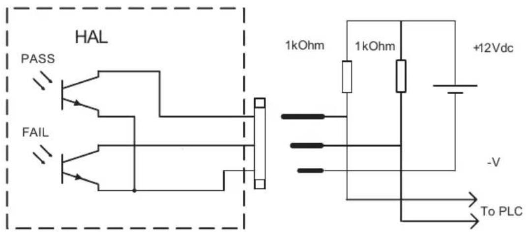
The Pass and Fail outputs follow the behaviour of the Indictors on the front of the tester, and are shown below. PLEASE NOTE THAT THE DIAGRAMS SHOW THE TYPICAL ON RESISTANCE FOR THE OPTOCOUPLER DEVICES WITHIN THE HAL.
PASS CONDITION

other
| Time | Event Type | |------|--------------------| | Start | TEST START | | End | TEST STOP (PASS) |FAIL CONDITION

line
| Time | Ohms PASS | Ohms FAIL | |------|-----------|-----------| | Start | 140 | 140 | | Test Start | 140 | 140 | | Test Stop (FAIL) | 140 | 140 | | RESET | 140 | 140 |The 'Mode Contacts' socket may be connected to a remote push-button switch or no-volt contact for resetting any fault status on the Hal, by activating the button or contact once only. Any further activation in this mode will default the Hal to its main menu. This is the same for the GREEN button which can be operated externally, in this way.
Warning: Do not connect any external voltage to this socket connection. These pins are connected to the Hal internal 5V DC supply. Damage will occur to the Hal if this occurs.
Hal 104/LED Control Ports
19 Way Connector
| Connector Position | Signal | Wire Style | H104 Position |
| A | 0V | Brown 16s | CN6 PIN 1 |
| B | Analogue 1 (0-4v) | Red 16s | CN6 PIN 2 |
| C | Analogue 2 (0-4v) | Orange 16s | CN6 PIN 3 |
| D | Analogue 3 (0-4v) | Yellow 16s | CN6 PIN 4 |
| E | Analogue 4 (0-4v) | Green 16s | CN6 PIN 5 |
| F | Analogue 5 (0-4v) | Blue 16s | CN6 PIN 6 |
| G | Analogue 6 (0-4v) | Violet 16s | CN6 PIN 7 |
| H | Analogue 7 (0-4v) | Grey 16s | CN6 PIN 8 |
| J | Analogue 8 (0-4v) | White 16s | CN6 PIN 9 |
| V | 0V | Black/Orange 16s | Earth Stud (M4 ring) |
| K | START | Black 16s | Solder to Start Button |
| L | START | Brown/Grey 16s | Solder to Start Button |
| M | STOP | Red/Black 16s | Solder to Stop Button |
| N | STOP | Orange/Violet 16s | Solder to Stop Button |
| P | Change-over Drive | Yellow/White 16s | Aux Switch COM |
| R | STATUS COM | Green/Grey 16s | J31 PIN 3 |
| S | STATUS PASS | Purple/Red 16s | J31 PIN 1 |
| T | STATUS FAIL | Grey/Red 16s | J31 PIN 2 |
| U | Power Drive | White/Orange 16s | RL1 Coil PIN 1 |
12 Way Connector
| Connector Position | Signal | Wire Style | H104 Position |
| A | +12V | Brown 16s | CN5 PIN 1 |
| B | Control 1 | Red 16s | CN5 PIN 2 |
| C | Control 2 | Orange 16s | CN5 PIN 3 |
| D | Control 3 | Yellow 16s | CN5 PIN 4 |
| E | Control 4 | Green 16s | CN5 PIN 5 |
| F | Control 5 | Blue 16s | CN5 PIN 6 |
| G | Control 6 | Violet 16s | CN5 PIN 7 |
| H | Control 7 | Grey 16s | CN5 PIN 8 |
| J | Control 8 | White 16s | CN5 PIN 9 |
| K | Aux I | Black 16s | J3 PIN 1 |
| L | Aux LK | Brown/Grey 16s | J3 PIN 2 |
| M | Aux 0V | Red/Black 16s | Earth Stud (M4 ring) |
Remote Command Protocol
1. Protocol Description
The Remote Command Protocol is an RS232 protocol that allows Clare testers to be reliably and quickly configured from a remote host and also allows the remote host to send commands to the instrument in order for the system to automatically perform electrical tests.
The protocol is based on an ASCII-HEX notation. That is, every byte of data is coded using two hex digits in the range '0' through '9', and 'A' through 'F'. Upper case ASCII hex must be used throughout. This is a common notation that allows easy detection of corrupted characters, and avoids the need for special encodings of control characters etc. The inefficiency of this encoding technique is of less concern than the benefits of simplicity and reliability.
The protocol is also line based. This means that a carriage return character, 0x0D, is used to terminate a command. This also implies that a command must start at 'the beginning' of a line – there must be no extraneous characters after the last CR and before the command, otherwise the whole command will be ignored as garbage.
Any request that is not properly formatted (eg missing characters, bad characters, bad length, bad CRC, etc), is silently ignored (as is a command that does not start ‘at the beginning of a line’). A host that does not receive an ACK, NAK, or interim ACK within a short period of time must assume that the transmission was corrupted, and issue a retry.
Within the protocol it is necessary to specify some values as multi-byte values. In all cases the protocol is defined as a ‘big-endian’ protocol – multi-byte values are always encoded with the most-significant-byte first. Thus a binary value of say 0x1B9C is sent as ASCII characters ‘1B9C’ in that order. Beware: ‘big-endian’ encoding is opposite to that found on PC architectures!
Requests from the host are formatted as follows:
Two ascii hex digits for an ever-incrementing command sequence number. A host should increment it's command sequence number before transmitting a command (but not when transmitting retries of the same command). The sequence number is copied to all
| responses generated. If the tester receives a command with a command sequence number the same as that for the previously correctly decoded command, then the tester simply re-sends its last response without performing any action – this deals with the situation where an ACK/NAK/InterimACK is corrupted before being received by the host. | |
| Two ascii hex digits representing the required command code. | |
| Two ascii hex digits indicating the item identifier. For many protocol commands the item identifier is not relevant and must be set to zero. | |
| Two ascii hex digits indicating the particular item instance (0 through N). For many protocol commands the item instance number is not relevant and must be set to zero. | |
| Four ascii hex digits indicating number of encoded data bytes in the request. Many protocol commands to not require any data to be supplied from the host, in which case the data size must be zero. | |
| Ascii hex representation of the data for commands that required strings, values, or structures. | |
| Four ascii hex digits representing the 16-bit CRC of all encoded bytes up to, but not including the CRC value itself. |
Responses from the tester take the following form:
| Two ascii hex digits representing the command sequence number received from the host in the command to which this response relates. | |
| Two ascii hex digits representing the response code (ACK, NAK, interim ACK). | |
| Four ascii hex digits indicating number of encoded data bytes in the response. | |
| Ascii hex representation of the NAK reason code (for NAK response code), contents, or the requested data (for ACK or interim ACK response codes). Some ACKs and interim ACKs do not return any data, in which casewill be zero. | |
| Four ascii hex digits representing the 16-bit CRC of all encoded bytes up to, but not including the CRC. Note that if the host includes the CRC value within the CRC calculation, then the result will always be zero for uncorrupted data. | |
| The end of line. This is always present. |
The CRC calculation is a standard 16-bit CRC (a proper CRC, not a checksum). The CRC, combined with the ASCII hex encoding technique, and including
2. Data Representation
Integer values
Commands or responses that require a single, discrete, integer value, may provide the value as between 1 and 4 bytes, encoded as between 2 and 8 ASCII hex characters. As has already been discussed, multi-byte values are encoded and transmitted in big-endian order.
NB: This does not include values that are part of structures! These are always encoded at an exact length.
String values
Many commands require string data. Often these commands expect more than one string, or possibly a variable number of strings. When transmitting strings, the string data is encoded as ASCII hex, just as for all other data. A null terminator must be encoded (as two ASCII '0' characters) between strings, but not after the final string. Thus sending no data counts as a single string of zero length, whereas sending a single null terminator byte counts as two zero length strings.
Although it is possible to send very long strings, and/or a great number of strings, the tester will always validate the received strings to ensure they are not too long, or that there are not to many. Strings that contain control codes will usually be rejected.
Floating point values
Floating point values are always 4 bytes in length, encoded as 8 ASCII hex digits. The tester uses IEEE encoding for floating point numbers. As has already been discussed, multi-byte values are encoded and transmitted in big-endian order.
Date and time structure
This structure is used when getting/setting the tester's date and time, or when reading the date and time at which the tester was calibrated.
typedef struct _ssscmddata_datetime {
    u16 year; // 1999,2001, etc, etc (sent/received in big-endian order)
    u8 month; // 1=Jan, 2=Feb, etc
    u8 day; // 1=1st, 2=2nd, etc
    u8 hour; // 0=midnight ... 23=11PM
    u8 minute; // 0 ... 59
    u8 second; // 0 ... 59
} ssscmddata_datetime;
3. Response Codes
There is a restricted set of response codes that can be generated by the tester. These response codes are always distinct from command codes.
SSSRSP_NAK (response code 0x00)
This response code is sent by the tester when a command is properly formatted in terms of the protocol wrapper (length, CRC, etc), but does not contain a properly formatted command (incorrect amount of data, unknown command, incorrect item id or item instance, etc), or if the command cannot be executed for some reason.
NAK responses sent by the tester always include 1 data byte. For a NAK this data byte is referred to as the NAK reason code. The following table describes the possible NAK reason codes:
| Mnemonic | Value | Description |
| SSSNAK_NO_SESSION | 0x01 | Cannot execute a command because no session has been started yet. |
| SSSNAK_PASSWORD | 0x02 | Either the password supplied for a session start request is incorrect, or an attempt has been made to perform a password protected command within a restricted session. |
| SSSNAK_INVALID_CMD | 0x03 | Unknown SSS protocol command. |
| SSSNAK_ITEM_ID | 0x04 | The specified item identifier is unknown or incorrect. |
| SSSNAK_INSTANCE | 0x05 | The specified item instance doesn't exist (instance number is too large). |
| SSSNAK_WRONG_CMD_TYPE | 0x06 | The command/item combination is incorrect (eg attempt to set a string with an integer value). |
| SSSNAK_INVALID_SIZE | 0x07 | Too much string data, wrong number of strings, or incorrect number of bytes (eg float or struct of incorrect size). |
| SSSNAK_INVALID_VALUE | 0x08 | Value/setting/parameter is outside of legal range, or bad characters within a string, etc. |
| SSSNAK_READ_ONLY | 0x09 | Cannot set item - it is read only. |
| SSSNAK_FUNCTIONALITY | 0x0A | Incomplete tester functionality - feature not implemented yet. |
| SSSNAK_OPERATION_SEQ | 0x0B | An operation is being attempted out of sequence (eg saving a testfile before a testfile download). |
| SSSNAK_FULL | 0x0C | Can't accept testfile entry, results upload, etc because there is insufficient space remaining. |
| SSSNAK_EE_FAILED | 0x0D | EEProm operation failed (eg flash erasure, programming, etc). |
SSSRSP_ACK_FINAL (response code 0x01)
This response code is issued for commands successfully received and completely processed by the tester. A final ACK may, or may not, contain response data. The data content depends on the command for which the response is being generated. For certain commands the SSSRSP_ACK_FINAL will be proceeded by one or more SSSRSP_ACK_INTERIM. In these cases the SSSRSP_ACK_INTERIM shows that a command has been successfully received by the tester, but that the command is still in progress.
SSSRSP_ACK_INTERIM (response code 0x02)
The SSSRSP_ACK_INTERIM response is used to provide immediate feedback to a host in order to show that a command has been successfully received by the tester, but that the command is still in progress. Interim acknowledgements are used in situations where flash EPROM needs to be erased and/or programmed, or when an electrical test is started.
Eventually the tester will respond with SSSRSP_NAK or SSSRSP_ACK_FINAL according to the outcome of the requested operation.
For flash EPROM operations only a single, empty, SSSRSP_ACK_INTERIM will be issued. The host should wait up to 30 seconds for the final ACK or NAK.
For electrical tests, SSSRSP_ACK_INTERIM responses will be issued continuously until the test completes. Each of these interim ACKs contains test status information (readings etc). The final ACK contains the overall test result and final reading. Up to ten interim ACKs may be transmitted per second – allowing time series results data to be compiled by the host.
4. General Protocol Commands
SSSCMD_SESSION_START (command code 0x10)
The “session start” command must be issued before any other protocol commands. This command is used to:
- Ascertain that the host and tester SSSCMD protocol implementation
- versions are compatible.
- Specify the baud rate for subsequent command exchanges.
- Supply any password that may be required for subsequent operations.
It is possible to send a session start command at any time – for example if a new baud-rate is required, or if password protection is to be temporarily enabled and then cancelled, or if the tester was left with a previous session still running. However, it is recommended that under normal circumstances, when a host has finished with a tester, that the host should send a session end command to ensure that any password protection is cancelled and that the tester drops back to 9600 baud.
The data associated with the session start command is as follows:
typedef struct _ssscmddata_session_start {
    u8 protocol_ver;
    u8 baud_code;
    u8 password_seed;
    u8 password[ARRAYSZ_SSS_PASSWORD];
} ssscmddata_session_start;
If the 'itemd id', 'instance', or amount of supplied data is incorrect, then the tester will respond with SSSRSP_NAK and the appropriate reason code.
protocol_ver
This describes the SSS CMD protocol version implemented by the host. Currently any value other than 0 will cause the command to be rejected with SSSRSP_NAK with the reason code set to SSSNAK_INVALID_VALUE.
baud_code
The required baud rate for subsequent communications:
0 = 9600 baud
1 = 19200 baud
2 = 28800 baud.
Any other value will cause the command to be rejected with SSSRSP_NAK with the reason code set to SSSNAK_INVALID_VALUE.
The tester sends the ACK or NAK at the prevailing baud rate before switching to the new baud rate.
When the tester is first placed into ‘remote mode’ it will always be listening for SSS commands at 9600 baud. Similarly after receiving an SSSCMD_SESSION_END command the tester drops back to 9600 baud. However, it is possible that a tester gets left in a state where a session continues running at different baud rate. Therefore a host should attempt to perform a session start command at 9600 baud, before trying 19200, then 28000. The supplied example software demonstrates baud-rate hunting when establishing sessions.
password_seed
If the tester does not have a password set, then the session will run as a unrestricted session, and the contents of 'password_seed' and 'password'] are ignored.
If the tester has a password set, and 'password_seed' is zero, to indicate that the host has not provided a password, then the tester ignores the contents of 'password[]', and the session will run as a restricted session - it will not be possible to perform commands for which an unrestricted session is required.
If the tester has a password set, and 'password_seed' is non-zero, then the seed is used to unscramble the contents of 'password[]'. If the unscrambled password matches the tester's password, then the session will run as an unrestricted session and the tester responds with SSSRSP_ACK_FINAL.. If the passwords do not match then the tester responds with SSSRSP_NAK with the reason code set to SSSNAK_PASSWORD.
password
If the host is supplying a password, then ‘password_seed’ must be non-zero, and the supplied password must be scrambled using the combination of the CRC lookup tables and the defined seed value. This allows passwords to be exchanged without them being readable on RS232 data loggers etc. It also allows the password to be supplied ‘differently’ each time – if, for example, a non-zero random number is used as the seed.
The function 'sss_start_session()' within the example software demonstrates how to scramble a password.
SSSCMD_SESSION_END (command code 0x11)
It is recommended, but not essential, to send a session end command after the host has finished with a tester. This ensures that any password protection is cancelled and that the tester drops back to 9600 baud. This makes is quicker to start the next session as the host can then always expect to send the initial session start request at 9600 baud.
If the 'itemd id', 'instance', or amount of supplied data is non-zero, then the tester will respond with SSSRSP_NAK and the appropriate reason code.
SSSCMD_NOP (command code 0x12)
This allows the host to solicit an ACK without performing any action. The example software uses SSSCMD_NOP as a confidence test after starting a session – primarily to check that the session baud rate is correct. Other host systems may wish to use SSSCMD_NOP to periodically ascertain that a session is still ‘alive’ if no other commands have been issued for a period of time.
If the 'itemd id', 'instance', or amount of supplied data is non-zero, then the tester will respond with SSSRSP_NAK and the appropriate reason code.
SSSCMD_CLEAR_SCREEN (command code 0x13)
This command turns off the tester's buzzer, and completely clears the tester's display. This may be useful if the default session message is not required.
If the 'itemd id', 'instance', or amount of supplied data is non-zero, then the tester will respond with SSSRSP_NAK and the appropriate reason code.
SSSCMD_RESET_SCREEN (command code 0x14)
This command turns off the tester's buzzer, clears the tester's display, and then re-displays the default session message.
If the 'itemd id', 'instance', or amount of supplied data is non-zero, then the tester will respond with SSSRSP_NAK and the appropriate reason code.
SSSCMD_SHOW_STRINGS (command code 0x15)
This command allows the tester's buzzer to be turned on/off, and/or for text to be placed on the tester's display.
If the 'itemd id', 'instance', or amount of supplied data is less than two bytes, then the tester will respond with SSSRSP_NAK and the appropriate reason code.
The first byte of the data supplied by the host is a combination of flag bits. Currently only two flag bits are defined:
| Mnemonic | Bit No | Description |
| SSSFLG_SHOW_STRING_BEEP_ON | 0 | Turns the beeper on before showing any strings. |
| SSSFLG_SHOW_STRING_BEEP_OFF | 1 | Turns the beeper off after showing any strings. |
If neither the SSSFLG_SHOW_STRING_BEEP_ON nor the SSSFLG_SHOW_STRING_BEEP_OFF bits are set, then the tester's buzzer is unaffected.
The next byte of the data supplied by the host is the screen line number at which to display any supplied strings. The top of the screen is line 0, and the bottom of the screen is line 23. The tester will reject the command if one or more of the supplied strings would be on a line outside the range 0 through 23.
The remainder of the data supplied by the host is string data. Null-terminators are used to separate multiple strings. Because the final string requires no null terminator, it follows that if no string data is
supplied (host supplies only 2 data bytes), then the host is defining a single empty string.
Each string is placed at the beginning of a line, and the remainder of the line is cleared. If text is required to be placed towards the right-hand side of the display, then the text must be preceded by spaces. An empty string simply clears an entire line. A host can define contiguous empty strings by providing contiguous null terminators.
Although the host may supply strings that are longer than the screen width, the tester will use only as many characters from each string as are needed to fill a single line.
5. System settings commands
The system settings may be read or modified using the commands defined in this section. Each system setting is identified with the 'item_id', and where items are array based the 'instance' is used to determine which array element is being addressed.
The tester is aware of the data type, the maximum array element 'instance' (which is zero if an item is not array based), and the value range and/or string length for each 'item_id'. The tester will respond with the appropriate error code if the wrong command type is used, or an item is otherwise incorrectly addressed.
See the following chapter for a list of the item identifiers, and their associated data types etc.
SSSCMD\_SS\_GET\_STRINGN (command code 0x20)
This command is used to read system settings that are based on strings. Some settings are for a single string, some are for two ore more strings. Where more than one string is returned, then the strings are separated by a null terminator. There is no null terminator after the final string.
SSSCMD\_SS\_SET\_STRINGN (command code 0x21)
This command is used to update system settings that are based on strings. Some settings are for a single string, some are for two ore more strings. Where more than one string is supplied, then the strings must be separated by a null terminator. There is no null terminator after the final string.
SSSCMD\_SS\_GET\_UINT (command code 0x22)
This command is used to read a system setting that is stored within the tester as an integer. The tester will supply between 1 and 4 data bytes, depending on the magnitude of the value being transmitted (rather than the potential maximum magnitude of a particular setting). When more than 1 byte is provided, the bytes are in big-endian order.
SSSCMD\_SS\_SET\_UINT (command code 0x23)
This command is used to update a system setting that is stored within the tester as an integer. The host may supply between 1 and 4 data bytes. When more than 1 byte is provided, the bytes must be in big-endian order.
SSSCMD\_SS\_GET\_FLOAT (command code 0x24)
This command is used to read a system setting that is stored within the tester as a 4 byte IEEE big-endian floating point number.
SSSCMD\_SS\_SET\_FLOAT (command code 0x25)
This command is used to update a system setting that is stored within the tester as a 4 byte IEEE big-endian floating point number. The host must supply exactly 4 bytes of data.
SSSCMD\_SS\_GET\_STRUCT (command code 0x26)
This command is used to read tester data that is stored as a collection of data bytes. Where values within the structure are multi-byte integers or floats, then these values are in big-endian order. Structures are always of a fixed sized – multi-bytes data values within the structure do not change in size according to their magnitude.
Example structures are the tester's current date and time, calibration date, printer settings, etc.
SSSCMD\_SS\_SET\_STRUCT (command code 0x27)
This command is used to update tester data that is stored as a collection of data bytes. Where values within the structure are multi-byte integers or floats, then these values are in big-endian order. Structures are always of a fixed sized – multi-bytes data values within the structure do not change in size according to their magnitude.
SSSCMD\_SS\_SAVE\_NOW (command code 0x2F)
This command is used to force the tester to update all variables that have been changed to be written to flash EPROM and/or battery backed NVRAM as appropriate. If this command is not issued and the tester is switched off without the user returning to the tester's main menu, then any changed settings will be lost.
6. System Settings Identifiers
SSSID_SOFTWARE_VERSION (Item_id = 0)
This read-only item is a string representing the software version number (eg "SNEU.26a", "AUNZSA.26a_beta3").
SSSID_HARDWARE_VERSION (Item_id = 1)
This read-only item is a string representing the hardware version (eg 1.23, 7.24, etc).
SSSID_SERIAL_NO (Item_id = 2)
This read-only item is a string representing the tester's serial number.
SSSID_CALIB_BY(Item_id = 3)
This read-only item is a string representing the name of the person or calibration rig that calibrated the tester.
SSSID_CALIB_AT (Item_id = 4)
This read-only item is a string representing the name of the place at which the tester was calibrated.
SSSID_CALIB_TIME(Item_id = 5)
This read-only item is a structure representing the date and time at which the tester was calibrated. The date and time structure is defined within the 'Data Representation' chapter.
SSSID_NUM_SERVICES (Item_id = 6)
This read-only item is an unsigned integer representing the number of times tester has been serviced. The value will be defined using either 1 or 2 bytes.
SSSID_TOTAL_APPLIANCES (Item_id = 7)
This read-only item is an unsigned integer representing the total number of products/appliances that have been tested by the tester. The value will be returned using up to 4 bytes.
SSSID\_TOTAL\_TESTS (Item\_id = 8)
This read-only item is an unsigned integer representing the total number of electrical tests that have been tested by the tester. The value will be returned using up to 4 bytes.
Many electrical tests may be performed for each product/appliance tested. In manual mode it is possible to perform electrical tests without beginning an appliance.
SSSID\_LASTSVC\_APPLIANCES (Item\_ld = 9)
This read-only item is an unsigned integer representing the total number of products/appliances that had been tested by the tester up to the time of the last service. The value will be returned using up to 4 bytes.
SSSID\_LASTSVC\_TESTS (Item\_id = 10)
This read-only item is an unsigned integer representing the total number of electrical tests that had been tested by the tester up to the time of the last service. The value will be returned using up to 4 bytes.
SSSID\_DATE\_TIME (Item\_id = 11)
This read/write item is a structure representing the tester's current date and time.
When setting the date and time the tester will reject requests that specify invalid dates and times.
SSSID\_SELIDX\_USER (Item\_id = 20)
This read/write item is an 8-bit unsigned integer representing the index of the currently selected user. This item is password protected if the user list is password protected.
Valid values are in the range 0 through 19 inclusive.
SSSID\_USER\_NAME (Item\_id = 21)
This read/write item is an array of strings representing the available user names. This item is password protected if the user list is password protected. Only a single user name can be read or written at a time. The valid range of instances is 0 through 19.
Each user name can contain up to a maximum of up to 10 non-null ASCII characters.
SSSID\_USER\_BUZZER (Item\_id = 22)
This read/write item is an array of 8-bit unsigned integers defining how the buzzer should be used for each user. This item is password protected if the user list is password protected. Only a single array entry can be read or written at a time. The valid range of instances is 0 through 19.
BUZZ_ON_KEY_PRESS = Bit 0
BUZZ_ON_TESTS = Bit 1
BUZZ_ON_BARCODE = Bit 2
BUZZ_ON_WARNING = Bit 3
SSSID\_USER\_LEVEL (Item\_id = 23)
This read/write item is an array of 8-bit unsigned integers defining the operational level for each user. This item is password protected if the user list is password protected. Only a single array entry can be read or written at a time. The valid range of instances is 0 through 19.
Novice = Value 0
Advanced = Value 1
SSSID\_USER\_STARTUP (Item\_id = 24)
This read/write item is an array of 8-bit unsigned integers defining the start-up mode for each user. This item is password protected if the user list is password protected.
Main Menu = Value 0
Manual Mode = Value 1
Remote Mode = Value 2
SSSID\_SELIDX\_SITE (Item\_Id = 30)
This read/write item is an 8-bit unsigned integer representing the index of the currently selected site.
Valid values are in the range 0 through 19 inclusive.
SSSID\_SITE (Item\_id = 31)
This read/write item is an array of strings representing the available site names. The valid range of instances is 0 through 19. Note that instance 0 is for the 'new...' menu entry. Normal list entries start at instance 1.
Each site name can contain up to a maximum of up to 15 non-null ASCII characters.
SSSID\_SELIDX\_LOCATION (Item\_id = 32)
This read/write item is an 8-bit unsigned integer representing the index of the currently selected location.
Valid values are in the range 0 through 49 inclusive.
SSSID\_LOCATION (Item\_id = 33)
This read/write item is an array of strings representing the available location names. The valid range of instances is 0 through 49. Note that instance 0 is for the 'new...' menu entry. Normal list entries start at instance 1.
Each location name can contain up to a maximum of up to 15 non-null ASCII characters.
SSSID\_SELIDX\_TEST (Item\_id = 34)
This read/write item is an 8-bit unsigned integer representing the index of the currently selected test. Note that index 0 represents the 'default sequence', index 1 represents 'use testcodes', and normal list entries start at index 2.
Valid values are in the range 0 through 21 inclusive.
SSSID\_DFLT\_SEQ\_TCODE (Item\_id ≡ 35)
This read/write item is a string representing the 'default sequence' testcode.
SSSID\_USE\_TCODES\_TCODE (Item\_id = 36)
This read/write item is a string representing the 'use testcodes' testcode.
SSSID_TEST_ENTRY (Item_id = 37)
This item represents an array of predefined tests. The information is encoded as two strings: the first is the test name, and the second is the testcode. The valid range of instances is between 0 and 19 inclusive.
A testname can have a maximum of 16 non-null characters. The length of the testcode depends on the software type.
SSSID_SELIDX_PHONE(Item_id = 38)
This read/write item is an 8-bit unsigned integer representing the index of the currently phone book number.
Note that index 0 represents the 'direct cable connection', index 1 represents 'manual dialing', index 2 represents 'new...', and normal list entries start at index 3.
The valid range of values is between 0 and 6 inclusive.
SSSID_PHONE_NEW_NUMBER (Item_ld = 39)
This read/write item is a string representing the 'new...' phonebook entry.
SSSID_PHONE_ENTRY (Item_id = 40)
This item represents an array of phonebook entries. The information is encoded as two strings: the first is the phone book name, and the second is the phone number. The valid range of instances is between 0 and 3 inclusive.
A phonebook name can have a maximum of 15 non-null characters. A phonebook number can have a maximum of 19 non-null characters.
SSSID_DL_FILE_NAME (Item_id = 41)
This read/write item is an array of strings representing the base filename to use with Z-Modem downloads.
Each array entry can have a maximum of 8 non-null characters.
Valid instances are 0 through 1 inclusive. Instance 0 defines the base name for a normal download, while instance 1 defines the basename for auto-download after a test.
SSSID\_DL\_SETTINGS (Item\_id = 42)
This read/write item is an array of structures representing the configuration of downloads.
Each structure contains exactly 7 bytes.
Valid instances are 0 through 1 inclusive. Instance 0 defines the settings to be used for normal downloads, while instance 1 defines the settings to be used when performing an auto-download after a test.
SSSID\_PASSWORD (Item\_id = 43)
This read/write item is a string representing the tester's password. This item is password protected - it is not possible to read/write this item unless the session is unrestricted.
$$ (I t e m _ i d \equiv 4 4) $$
Not Used
$$ (I t e m _ i d = 4 5) $$
Not Used
SSSID\_FAILURE\_ACTION (Item\_id = 46)
This read/write item is an 8-bit unsigned integer representing the action to take if a test fails during automatic test mode. This item cannot be written unless the session is unrestricted.
Valid values are 0 through 1 inclusive. 0=fail appliance, 1=show failure menu.
SSSID\_ROLL\_PRINTER (Item\_id = 47)
This read/write item is an 8-bit unsigned integer representing the type of any connected roll printer. This item cannot be written unless the session is unrestricted.
$$ 0 = \text { TSP400 }, 1 = \text { MARTEL } $$
SSSID\_APP\_NUMBER\_HANDLING (Item\_id = 48)
This read/write item is an 8-bit unsigned integer representing how to generate the initially offered product/appliance test numbers within the 'new appliance' menu.
This item cannot be written unless the session is unrestricted.
Valid values are 0 through 2 inclusive. 0=show a blank product/appliance number, 1=show the last used product/appliance number, 2=show an incremented version of the last used product/appliance number.
SSSID\_COMMENTS\_CONDITION (Item\_id = 49)
This read/write item is an 8-bit unsigned integer representing whether or not to request comments after completing a test.
This item cannot be written unless the session is unrestricted.
Valid values are in the range 0 through 3 inclusive. 0=always request comments, 1=request comments when a product/appliance passes, 2=request comments when a product/appliance fails, 3=never request comments.
SSSID\_COMMENTS\_DESIGNTRS (Item\_id = 50)
Not Used
SSSID\_AFTER\_TEST\_ACTION (Item\_id = 51)
This read/write item is an 8-bit unsigned integer representing the action to take uponcompleting an auto-mode test. This item cannot be written unless the session is unrestricted.
Valid values are 0 through 2 inclusive. 0=show menu, 1=new test, 2=download then new test.
SSSID_SYS_FLAGS (Item_id = 52)
This read/write item is a 16-bit unsigned integer containing various system settings flags.
This item cannot be written unless the session is unrestricted.
Bit 0, if set: date and time to be shown in American mm/dd/yyyy format
SSSID_PASSWD_PROTECT_FLAGS (Item_id = 53)
This read/write item is a 16-bit unsigned integer containing various password protection flags.
This item cannot be written unless the session is unrestricted.
Bit 0 : PASSWD_PROTECT_DATE_TIME
Bit 1 : PASSWD_PROTECT_EDIT_USERS
Bit 2 : PASSWD_PROTECT_EDIT_SITE_LOC
Bit 3 : PASSWD_PROTECT_EDIT_PHONE
Bit 4 : PASSWD_PROTECT_CHANGE_USER
Bit 5 : PASSWD_PROTECT_CHANGE_SITE_LOC
Bit 6 : PASSWD_PROTECT_MANUAL_MODE
Bit 7 : PASSWD_PROTECT_REMOTE_MODE
Bit 8 : PASSWD_PROTECT_DOWNLOAD_MODE
Bit 9 : PASSWD_PROTECT_CLEAR_RESULTS
Bit 10 : PASSWD_PROTECT_CLEAR_UPLOAD
Bit 11 : PASSWD_PROTECT_BCPRINT_LISTS
SSSID_TEST_SELECTION (Item_id = 54)
This read/write item is an 8-bit unsigned integer representing the restrictions to place uponthe ability to select items within the test selection menu. This item cannot be written unless the session is unrestricted.
Valid values are in the range 0 through 2 inclusive. 0=allow selection of any test, 1=selection via barcode only, 2=fixed test selection.
SSSID_SELIDX_FIXED_TEST (Item_id = 55)
This read/write item is an 8-bit unsigned integer representing the test to be used if fixed test selection is in force.
This item cannot be written unless the session is unrestricted.
Valid values are in the range 0 through 19 inclusive.
SSSID_PASS_FAIL_TITLE (Item_id ≡ 56)
This read/write item is a string representing the title to be used for pass/fail labels.
This item cannot be written unless the session is unrestricted. The string may be up to a maximum of 30 non-null characters.
SSSID_PRODUCT_TEST_TITLE (Item_id ≡ 57)
This read/write item is a string representing the title to be used for product / testcode labels. This item cannot be written unless the session is unrestricted.
The string may be up to a maximum of 30 non-null characters.
SSSID_ROLLPRN_BAUD_RATE (Item_id = 58)
This read/write item is an 8-bit unsigned integer representing the baud rate to be used with the roll printer.
This item cannot be written unless the session is unrestricted.
Valid values are in the range 0 through 1 inclusive. 0=9600 baud, 1=19200 baud.
SSSID_MANMODE_SETTINGS (Item_id = 59)
This read/write item is an array of structures representing the settings for manual mode 'memories'
Valid instances are in the range 0 through 9 inclusive.
Each structure is 20 bytes long.
This item cannot be written unless the session is unrestricted.
SSSID_MANMODE_NAME (Item_id = 60)
This read/write item is an array of strings representing the names for manual mode 'memories'
Valid instances are in the range 0 through 9 inclusive.
Each string can contain a maximum of 16 non-null characters.
This item cannot be written unless the session is unrestricted.
SSSID\_MANMODE\_SELECTION (Item\_id = 61)
This read/write item is an 8-bit unsigned integer representing the manual mode 'memory' to recall when next powering the tester.
This item cannot be written unless the session is unrestricted. Valid values are in the range 0 through 9 inclusive.
7. Testfile Upload Commands
The SSS command protocol allows a fast and efficient means of creating testfiles. The purpose of the testfile is covered by alternate tester documentation.
SSSCMD\_TESTFILE\_RESTART (command code 0x30)
This command is used to clear the SRAM testfile assembly area. This command must be issued immediately prior to providing testfile entries.
If the 'itemd id', 'instance', or amount of supplied data is non-zero, then the tester will respond with SSSRSP_NAK and the appropriate reason code.
SSSCMD\_TESTFILE\_ENTRY (command code 0x31)
This command is used to add an appliance name & testcode (and possibly a site and location) to the SRAM testfile assembly area. The command will fail if testfile assembly has not previously been initiated with the SSSCMD_TESTFILE_RESTART command.
The host must supply between 2 and 4 strings:
The appliance/product number.
The testcode to use when testing this appliance/product.
An optional site name at which this appliance is expected to be located.
An optional location name at which this appliance is expected to be located.
If the 'itemd id' or 'instance' are non-zero, then the tester will respond with SSSRSP_NAK and the appropriate reason code. Similarly the tester will respond with a NAK if there are too few or too many strings, any of the strings are too short or too long, etc.
SSSCMD\_TESTFILE\_SAVE\_NOW (command code 0x32)
This command is used to commit the SRAM testfile assembly area into flash memory. The tester will respond with an interim ACK before eventually issuing a final ACK or NAK.
If the 'itemd id', 'instance', or amount of supplied data is non-zero, then the tester will respond with SSSRSP_NAK and the appropriate reason code.
8. Tester Commands
The following commands are associated with performing electrical tests on the HAL range.
SSSCMD\_HAL\_QUERY\_STATE (command code 0x80)
This command is used to establish the state of various inputs to the tester such as the guard switch, remote probe switch, etc. The tester always returns two bytes representing 16 flag bits.
Currently only bit 0 if defined: this bit is set if the external guard switch is closed.
If the 'itemd id', 'instance', or amount of supplied data is non-zero, then the tester will respond with SSSRSP_NAK and the appropriate reason code.
SSSCMD\_HAL\_BARCODE\_OR\_KEY (command code 0x81)
This command is used to obtain barcode or keyboard input from the HAL tester.
The host specifies a single byte of data that represents the number of seconds to wait for a response. This can be in the range 0 through 255. The value of 255 is a special case representing an infinite timeout.
The tester issues an empty interim acknowledgement, switches the RS232 monitoring to the barcode port, then waits between 0 and 254 seconds, or an infinite time, for a barcode or keypress, then sends back the result in a final ACK.
The tester's final ACK contains 1 or more bytes. The first byte defines the event that terminated the command:
SSSVAL_BARCODE_OR_KEY_TIMEOUT 0x00
SSSVAL_BARCODE_OR_KEY_F1 0x06
SSSVAL_BARCODE_OR_KEY_F2 0x07
SSSVAL_BARCODE_OR_KEY_F3 0x08
SSSVAL_BARCODE_OR_KEY_F4 0x09
SSSVAL_BARCODE_OR_KEY_ABORT 0x0B
SSSVAL_BARCODE_OR_KEY_START 0x0C
SSSVAL_BARCODE_OR_KEY_BARCODE 0x1F
If, and only if, the first byte is
SSSVAL_BARCODE_OR_KEY_BARCODE, then the tester will also return the string data for the barcode. This barcode will be of variable length, and the tester does not return the null-terminator.
If the 'itemd id', 'instance', or amount of supplied data is not one byte, then the tester will respond with SSSRSP_NAK and the appropriate reason code.
SSSCMD\_HAL\_PERFORM\_TEST (command code 0x82)
This command is issued by a host in order to perform an electrical test on the HAL tester.
The 'item_id' is used to determine the type of test to be performed:
SSSID_HAL_TEST_TYPE_HIPOT_50 1
SSSID_HAL_TEST_TYPE_HIPOT_60 2
SSSID_HAL_TEST_TYPE_HIPOT_DC 3
SSSID_HAL_TEST_TYPE_DCIR 4
SSSID_HAL_TEST_TYPE_EBOND_50 5
SSSID_HAL_TEST_TYPE_EBOND_60 6
SSSID_HAL_TEST_TYPE_PWRLK 7
SSSID_HAL_TEST_TYPE_PWRTLK 8
The ‘instance’ must be set to 0.
The host provides test parameters within the data area of the command. The following structure defines the test parameters. Note that all multi-byte values are in big-endian order:
typedef struct _ssscmddata_haltest {
    u8 test_flags; // Reserved, must be zero
    u8 test_start; // SSSVAL_HAL_TSTART_xxxx
    u16 target_output; // Target output in volts or milli-amps
    u16 time_ramp_tgt; // Time in tenths of a second to ramp to target voltage
    u16 time_hold; // Time in tenths of a second to hold target voltage
u16 time_ramp_zero; // Time in tenths of a second to ramp to zero volts
union {
    float r; // Generic access
    float milli_amps; // HIPOT. Used only at end of test for pass/fail determination.
    float mega_ohms; // DCIR. Used only at end of test for pass/fail determination.
    float milli_ohms; // EBOND. Used only at end of test for pass/fail determination.
} lo_limit;
union {
    float r; // Generic access
    float milli_amps; // HIPOT. Test fails immediately if this limit exceeded.
    float mega_ohms; // DCIR. Used only at end of test for pass/fail determination.
    float milli_ohms; // EBOND. Used only at end of test for pass/fail determination.
} hi_limit;
u8 arc_detect; // 0 thru 9, 0=off, 1=most sensitive, ..., 9=least sensitive
u8 channel; // HAL: 0, HALSCAN: 0 thru 4, G2 0=front, 1=rear
} ssscmddata_haltest;
test\_start
One of the following:
| SSSVAL_HAL_TSTART_NONE | 0 | No special start conditions (test will fail if guard switch is open) |
| SSSVAL_HAL_TSTART_STARTK | 1 | Start key must be pressed (test will fail if guard switch is open) |
| SSSVAL_HAL_TSTART_GSW | 2 | Guard switch must opened and then closed |
| SSSVAL_HAL_TSTART_GSW_STARTK | 3 | Guard switch must opened and then closed, then the start key pressed |
For earth bond tests the earth bond probe micro switch operates in parallel with the start button. The micro switch is ignored for other test types, or until the guard switch has been opened and closed should this also form part of the start conditions.
target\_output
For HV tests this is the required output voltage in volts.
For EBOND tests this is the required output current in milli-amps.
For PWR tests this field is reserved and should be set to zero.
time\_ramp\_tgt
For HV and EBOND tests this is the time to ramp to required output in tenths of a second.
For PWR tests this field is reserved and should be set to zero.
time_hold`
For HV and EBOND tests this is the length of the hold phase in tenths of a second.
For PWR tests this is the duration for which power is applied in tenths of a second.
time_ramp_zero
For HV and EBOND tests this is the time to ramp down to zero output in tenths of a second.
For PWR tests this field is reserved and should be set to zero.
lo_limit1
The primary lower limit for all test types. This lower limit is only checked after the end of a test.
hi_limit1
The primary upper limit for all test types. For HIPOT and PWR tests the test will fail immediately if this upper limit is exceeded. For other test types this limit is only checked after the end of a test.
lo_limit2
Required only for PWR test types this field defines the lower kVA limit. This limit is only checked after the end of a test.
hi_limit2
Required only for PWR test types this field defines the upper kVA limit. This limit is only checked after the end of a test.
lo_limit3
Required only for PWR test types this field defines the lower power factor limit. This limit is only checked after the end of a test.
hi_limit3
Required only for PWR test types this field defines the upper power factor limit. This limit is only checked after the end of a test.
arc_detect
For HV tests this is the arc detection level, 0 through 9. Set to 0 to disable arc detection, otherwise 1 is the most sensitive detection level, and 9 is the least sensitive level.
For EBOND and PWR tests this field is reserved and should be set to zero.
Channel
For HV tests:
For a basic HAL this must be 0
For a HALSCAN use 0 through 4 represent the required
connection
For a G2 use 0 for the front panel connection, and 1 for the rear connection
For EBOND tests the channel must be 0.
For PWRLK and PWRLK tests 0 represents standard polarity, and 1 for reverse polarity.
For interim ACKs and final ACKs, the tester responds with the data content representing the following structure. Again, multi-byte values are in big-endian order.
typedef struct _sssack_haltest {
    u8 test_state;
    u16 test_time; // Test time in tenths of a second
    union {
    u16 w; // Generic access
    u16 test_volts; // HIPOT/DCIR: Applied test volts
    u16 milli_aps; // EBOIND: Applied test current
    } test_applied;
    union {
    float r; // Generic access
    float milli_amps; // Measured HIPOT leakage
    float mega_ohms; // Measured DCIR value
    float milli_ohms; // Measured earth bond resistance
    } test_reading;
} sssack_haltest;
The time and readings are either the latest values (interim ACK), or the values captured at the end of the hold phase (final ACK). Do not use the values within a final ACK if the test was aborted (determined by inspecting the test state).
There are two distinct sets of test states: those that can be sent as part of an interim ACK, and those that can be sent as part of a final ACK:
Test states only sent as part of an interim ACK
These states have the highest bit clear to differentiate them from final result states:
| SSSVAL_HAL_TSTATE_COMMAND_RECEIVED | 0x00 | First interim ACK. |
| SSSVAL_HAL_TSTATE_WAITING_FOR_START | 0x01 | Waiting for start conditions (sent once per second). |
| SSSVAL_HAL_TSTATE_PREPARING_HARDWARE | 0x02 | Getting hardware and channel relays ready |
| SSSVAL_HAL_TSTATE_RAMPING_TO_TARGET | 0x03 | Test has started, ramping voltage up. |
| SSSVAL_HAL_TSTATE_HOLDING | 0x04 | Hold phase, final reading captured at end of this phase |
| SSSVAL_HAL_TSTATE_RAMPING_TO_ZERO | 0x05 | Ramping voltage back to zero. |
Test states only sent as part of a final ACK
These states have the highest bit set to differentiate them from ongoing test states:
| SSSVAL_HAL_TSTATE_PASSED | 0x80 | Test passed |
| SSSVAL_HAL_TSTATE_FAILED_UPPER_LIMIT | 0x90 | Test failed: result is above upper limit |
| SSSVAL_HAL_TSTATE_FAILED_LOWER_LIMIT | 0x91 | Test failed: result is below lower limit |
| SSSVAL_HAL_TSTATE_ABORTED_HW_SHUTDOWN | 0xA0 | Test aborted: no specific cause detected |
| SSSVAL_HAL_TSTATE_ABORTED_GUARD_SWITCH | 0xA1 | Test aborted: guard switch input was open |
| SSSVAL_HAL_TSTATE_ABORTED_KEY | 0xA2 | Test aborted: abort key was pressed |
| SSSVAL_HAL_TSTATE_ABORTED_OVER_CURRENT | 0xA3 | Test aborted: over-current detected |
| SSSVAL_HAL_TSTATE_ABORTED_OVER_TEMP | 0xA4 | Test aborted: over-temperature detected |
| SSSVAL_HAL_TSTATE_ABORTED_ARC | 0xA5 | Test aborted: arc detected |
| SSSVAL_HAL_TSTATE_ABORTED_FEEDBACK | 0xA6 | Test aborted: no data from Measurement PIC |
| SSSVAL_HAL_TSTATE_ABORTED_GUI_TIMEOUT | 0xA7 | Test aborted: no data from GUI (inter-packet-gap timeout) |
| SSSVAL_HAL_TSTATE_ABORTED_GUI_REQUEST | 0xA8 | Test aborted: received a STOP request |
| SSSVAL_HAL_TSTATE_ABORTED_SOFTWARE_ERROR | 0xA9 | Test aborted: invalid conditions found (glitch etc) |
| SSSVAL_HAL_TSTATE_ABORTED_ESCAPE | 0xAA | Test aborted: ESC character received on the serial port |
| SSSVAL_HAL_TSTATE_ABORTED_NO_READING | 0xAB | Test aborted: no result reading was available |
| SSSVAL_HAL_TSTATE_ABORTED_RSVD11 | 0xAC | Test aborted: reserved cause |
| SSSVAL_HAL_TSTATE_ABORTED_RSVD12 | 0xAD | Test aborted: reserved cause |
| SSSVAL_HAL_TSTATE_ABORTED_RSVD13 | 0xAE | Test aborted: reserved cause |
Clare is a division of

SEAWARD
GROUP


- Limited Warranty & Limitation of Liability
- © Copyright 2017
- E&OE
- Disposal of Old Product
- User Note:
- Table of Contents
- CHAPTER 4 TIPS & TROUBLESHOOTING 82
- CHAPTER 5 MAINTAINING THE TESTER 85
- CHAPTER 6 ACCESSORIES 87
- CHAPTER 7 SPECIFICATIONS 89
- APPENDIX A PURPOSE OF TESTS 94
- APPENDIX B REFERENCE 97
- TEST CODE TABLES 98
- ADDENDUM NOTES 122
- REMOTE COMMAND PROTOCOL 128
- Before Starting
- Safety
- Safety Precautions
- Warning
- Chapter 1 Introducing the Tester
- Hal 101
- Hal 102
- Hal 103
- Hal 104 / LED
- The Front Fascia
- Definitions
- Quick Reference
- Editing the date in all modes
- Entering a User Name
- Editing User Level and Novice Mode
- Storing Product Test Results in Automatic mode
- Storing Product Test Results in Manual mode
- Storing System Data
- Waiting for a Yes/Cancel response
- Using Symbols in Text Fields
- Digit Restriction
- Setting up a Password
- Abbreviation used:
- Chapter 2 Connecting the Tester
- Connecting the tester
- Chapter 3 Using the Tester
- Introduction
- Note
- How to....
- How to perform Automatic Tests
- Test Settings
- Default Sequence
- Description of Fields setting and Icons for Test Start conditions:
- Use Test codes
- Perform Test
- Add Comments
- Options after Test
- New Test
- Review Test Results
- Download Test Results
- Abort Actions
- Restart Test
- Restart Product
- Abort Test
- Abort Product
- End Current Loop
- How to use the Meter Display
- -5
- 图图
- Sample Automatic Mode Meter Display
- How to view (search) Test Results
- Search result through Product Number
- Search result through Site Name
- Search result through Location Name
- Search result through User Name
- Test Status
- Storage Status
- Date From
- Date To
- Start Search
- Search Result
- Product Test Results
- How to perform Manual Tests
- Entering Manual Mode
- Create Product Number
- Performing a Manual Test
- Enter Comments/Save Results
- How to download Data (Results)
- Destination & Download Format
- Product Number
- Site Name
- Location Name
- User Name
- Search
- To print Barcode Pass/Fail Labels
- How to print Barcode Labels and Test codes
- To print barcode test codes
- To print barcode Product & Test Type
- How to use Setup
- Edit Test Settings
- Test Settings Editor
- Name:
- Test Parameter Fields
- Test codes
- Store Settings
- Print Test codes
- PRINTING TESTCODES WORKING....
- Edit User List / Options
- Edit User Name
- Name
- User Level
- Startup Mode
- Beep on Key Press
- Beep on Tests
- Beep on Barcodes
- Beep on Warning
- Saving User Settings
- Edit Site List
- Edit Site Name
- Edit Location List
- Edit Location Name
- Change Date / Time
- System Configuration
- How to edit System Configuration
- Product Number: (Three options selectable)
- On Test Failure: (Two options)
- - Failure Menu
- - End Product
- Test Type: (Three options)
- Any
- - Barcode only
- Comments:
- After Test:
- Date Format:
- Roll Printer: (REF 283A954)
- Password Protection Options
- Change Password
- Set Brightness
- Factory Settings
- How to use the Memory
- View Memory Capacity
- Perform Memory Test
- Delete Single Product
- Note:
- Clear Results Memory
- Clear Upload Memory
- How to Change User Name
- How to Change Site Name
- How to Change Location Name
- How to use Help
- Help provided to the User
- Description of Test
- How to Perform Tests
- Why tests fail
- The effect of User Levels during Test Sequences
- Novice User Level
- Advanced User Level
- Chapter 4 Tips & Troubleshooting
- Power -On Self tests:
- Temperature monitoring
- Barcodes
- Barcode Scanner Specification
- When to use a Barcode Scanner
- Interfacing
- Downloading to Computer Software
- Serial Port
- Chapter 5 Maintaining the Tester
- Cleaning the Tester
- User Maintenance
- For Service and calibration contact:-
- Chapter 6 Accessories
- Chapter 7 Specifications
- Input Rating
- Display
- Environmental Specifications
- Mechanical Specification
- Safety Specifications
- AC HiPot Test (All Models)
- DC HiPot Test (All Models)
- Powered Leakage Tests (H104/HLED)
- Power Output Rating
- Output Power Measurement (H104)
- Output Power Measurement (HLED)
- Single Phase Power Factor Measurement
- Leakage Current Measurement
- Touch Current Measurement
- Appendix A Purpose of Tests
- Insulation Test
- Hipot Test
- Ground (Earth) Bond Test
- 6V (no-load) 0-40A AC test Current
- Powered Load and Leakage Test
- Caution
- Appendix B Reference
- Factory-set Test Sequences
- Test code Tables
- Digit 1 (Character 1) – Test code Type
- Digit 2 – Test Type
- Digit 3 – Start Conditions & Base Target Voltage
- Digit 4 – Target Voltage Offset
- Digit 5 – Ramp to Target Time
- Digit 6 – Hold Time
- Digit 7 – Ramp to Zero Time
- Digit 10 Arc Detection Sensitivity (AC/DC HIPOT & DC IR)
- Digit 10 – Arc Detection Level (Hal)
- Digit 10 - Arc Detection Level (H102)
- Digit 11 – Loops to Perform
- Addendum Notes
- HAL Series Remote Connection for Pass/Fail Indications and Remote Fault Reset
- Hal 104/LED Control Ports
- Remote Command Protocol
- Protocol Description
- Requests from the host are formatted as follows:
- Data Representation
- String values
- Floating point values
- Date and time structure
- Response Codes
- General Protocol Commands
- System settings commands
- SSSCMD\_SS\_GET\_STRINGN (command code 0x20)
- SSSCMD\_SS\_SET\_STRINGN (command code 0x21)
- SSSCMD\_SS\_GET\_UINT (command code 0x22)
- SSSCMD\_SS\_SET\_UINT (command code 0x23)
- SSSCMD\_SS\_GET\_FLOAT (command code 0x24)
- SSSCMD\_SS\_SET\_FLOAT (command code 0x25)
- SSSCMD\_SS\_GET\_STRUCT (command code 0x26)
- SSSCMD\_SS\_SET\_STRUCT (command code 0x27)
- SSSCMD\_SS\_SAVE\_NOW (command code 0x2F)
- System Settings Identifiers
- SSSID\_TOTAL\_TESTS (Item\_id = 8)
- SSSID\_LASTSVC\_APPLIANCES (Item\_ld = 9)
- SSSID\_LASTSVC\_TESTS (Item\_id = 10)
- SSSID\_DATE\_TIME (Item\_id = 11)
- SSSID\_SELIDX\_USER (Item\_id = 20)
- SSSID\_USER\_NAME (Item\_id = 21)
- SSSID\_USER\_BUZZER (Item\_id = 22)
- SSSID\_USER\_LEVEL (Item\_id = 23)
- SSSID\_USER\_STARTUP (Item\_id = 24)
- SSSID\_SELIDX\_SITE (Item\_Id = 30)
- SSSID\_SITE (Item\_id = 31)
- SSSID\_SELIDX\_LOCATION (Item\_id = 32)
- SSSID\_LOCATION (Item\_id = 33)
- SSSID\_SELIDX\_TEST (Item\_id = 34)
- SSSID\_DFLT\_SEQ\_TCODE (Item\_id ≡ 35)
- SSSID\_USE\_TCODES\_TCODE (Item\_id = 36)
- SSSID\_DL\_SETTINGS (Item\_id = 42)
- SSSID\_PASSWORD (Item\_id = 43)
- SSSID\_FAILURE\_ACTION (Item\_id = 46)
- SSSID\_ROLL\_PRINTER (Item\_id = 47)
- SSSID\_APP\_NUMBER\_HANDLING (Item\_id = 48)
- SSSID\_COMMENTS\_CONDITION (Item\_id = 49)
- SSSID\_COMMENTS\_DESIGNTRS (Item\_id = 50)
- SSSID\_AFTER\_TEST\_ACTION (Item\_id = 51)
- SSSID\_MANMODE\_SELECTION (Item\_id = 61)
- Testfile Upload Commands
- SSSCMD\_TESTFILE\_RESTART (command code 0x30)
- SSSCMD\_TESTFILE\_ENTRY (command code 0x31)
- SSSCMD\_TESTFILE\_SAVE\_NOW (command code 0x32)
- Tester Commands
- SSSCMD\_HAL\_QUERY\_STATE (command code 0x80)
- SSSCMD\_HAL\_BARCODE\_OR\_KEY (command code 0x81)
- SSSCMD\_HAL\_PERFORM\_TEST (command code 0x82)
- test\_start
- target\_output
- time\_ramp\_tgt
- SEAWARD
Brand : Seaward
Model : H101
Category : Electronic Tester