
EM 524 90 - Detector Eberle - Free user manual and instructions
Find the device manual for free EM 524 90 Eberle in PDF.


| Product Type | Ice Detector / Snow Melt Controller (2-zone) |
| Brand | Eberle |
| Model | EM 524 90 |
| Number of Zones | 2 (independent Zone A and Zone B) |
| Operating Voltage | AC 230 V ±10%, 50/60 Hz |
| Power Consumption | ≤ 25 VA |
| Heating Output Relays | 2 relays, each AC 250 V, 16 A (cos φ=1) / 4 A (cos φ=0.6) |
| Alarm Relay | 1 changeover contact, AC 250 V, 2 A (cos φ=1) / 0.8 A (cos φ=0.6) |
| Display | 2-row, 16-digit LCD; shows temperatures, moisture, heating status, alarms |
| Control Buttons | 4 buttons: MENU, +, -, ENTER |
| Ambient Temperature Range | -20 °C to +50 °C (-4 °F to 122 °F) |
| Storage Temperature Range | -20 °C to +70 °C (-4 °F to 158 °F) |
| Protection Class | II (with proper installation) |
| Enclosure Protection | IP 20 |
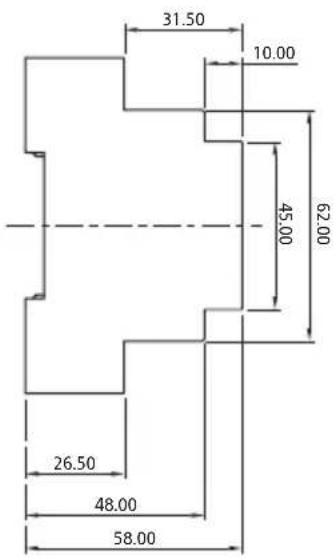
| Housing Dimensions (H x W x D) | 159 mm x 90 mm x 58 mm (with 45 mm cutout) |
| Weight (without sensors and packaging) | approx. 780 g |
| Applicable Standards | EN 60730 |
| Supported Languages | German, English, French, Finnish, Swedish, Czech, Dutch, Hungarian, Turkish, Polish, Italian |
| Sensor Inputs | Ice/snow sensor (ESF 524 001/011 or ESD 524 003), ground temperature sensor (TFF 524 002/012 or TFD 524 004), optional air temperature sensor (TFD 524 004) |
| Adjustable Parameters | Range, Temperature, Moisture, Base Temperature, After-run Time, Operation Mode (Automatic/Permanent), Sensor Heater, Language, Temp Unit |
| Maintenance | Keep sensor surfaces clean; inspect control unit regularly for alarms |
| Mounting | Snap-on mount on DIN rail EN 50022-35S |
Frequently Asked Questions - EM 524 90 Eberle
User questions about EM 524 90 Eberle
0 question about this device. Answer the ones you know or ask your own.
Ask a new question about this device
Download the instructions for your Detector in PDF format for free! Find your manual EM 524 90 - Eberle and take your electronic device back in hand. On this page are published all the documents necessary for the use of your device. EM 524 90 by Eberle.
USER MANUAL EM 524 90 Eberle
operating instructions Ice detector
EM 524 89
EM 524 90
for open spaces and gutter heating

Contents
Instructions/General Descriptions....3
Menu mode 4
Menu items 8
Alarm messages 10
Design....11
Operating 11
Sensor for open spaces.... 12
Combined temperature and moisture sensor 13
Sensor assembly....14
Installation examples.... 18
Ice and snow sensor 20
Temperature sensor 21
Setting desired values 23
Operating modes. 24
Maintenance 26
Storage program 26
Connection diagrams 27
Appendix:
Technical data....33
Dimensions 35
Brief operating instructions 36
WARNING:
This independent electronic device can be installed for the fully automatic electric heating of open spaces, garage drives, stairs, ramps, flat roofs and gutters.
The device must only be installed by a qualified electrician in accordance with the connection diagram. Pay strict attention to the latest electrical safety standards and the local electricity supply company's safety instructions. The device is intended for installation in control cabinets or distributors. To achieve protection class II the appropriate installation measures must be taken. The device complies with EN 60730 and works in accordance with operating mode 1C.
Proper operation is only possible if the system is installed before there is frost or snow and not when the open spaces or gutters to be heated are already covered with snow or ice. It is recommended that the system is left on during the entire heating period!
Note!
The system will only work properly if the thermal output of the space to be heated has been calculated properly or adapted to local conditions. Please contact your system installer
Instructions
The ice detector is installed for the fully automatic electric heating of open spaces, garage drives, stairs, ramps, flat rooves and gutters. Unlike manually controlled (touch-dependent) or thermostatically controlled (only temperature dependent) systems, the heating will only be switched on if there is a danger of slippery conditions, i.e. snow, ice or sleet and will, naturally, be switched off after thawing. This ensures energy savings of up to 80% compared with thermostatically controlled systems.
General description 2-zone EM 524 90 and 1-zone EM 524 89
The 2-zone device is a dual device. It combines the function of two EM 524 89 regulators in one housing. Apart from this dual nature, the single zone EM 524 89 has the same features and capability.
There is a combined LCD display, input buttons and combined electronics.
There are two of all the other features. A dual set of sensors for temperature and moisture. Two separate relays for the heating circuits.
There is one sensor for air temperature, for detection of a sudden drop in temperature, and this is used jointly. There is only one alarm relay.
The two separately functioning parts of the device are called zones, Zone A and Zone B.
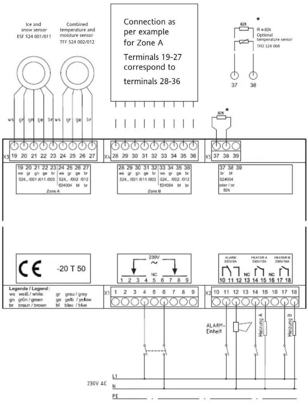
The zone A sensors are connected to the group of terminals 19 to 27.
The zone B sensors are connected to the group of terminals 28 to 36.
The zone A heating circuit is connected to terminals 14 and 15.
The zone B heating circuit is connected to terminals 17 and 18.
EM 52489: the sensors are connected to the group of terminals 10 to 19.
the heating circuit is connected to terminals 8 and 9.
The functionalities of both zones work completely independently of each other.
All of the above-mentioned sensors can be used for each of the zones independently of each other in any combination you wish.
Both zones can be set independently in various ways using the menu. Constant display of the operating status also takes place separately according to the zones, whereas the LED indicator lights on the front panel show the zone which is currently being displayed.
When operating the device, in order to be able to distinguish between both parts of the device, there is a menu item called “Zone”, which can be used to switch between the menus for both zones. The two LED diodes on the front panel indicate which of the menus you are currently viewing.
Language settings and settings for display of °C / °F always apply for both parts of the device, whereas all other settings relate only to the relevant zone.
1-zone controller
The ice detector settings can be monitored and adjusted using 3 buttons and a two-line 16-digit display.
Button MENU: This button is used to call up the individual menu items.
Button VALUE: This button is used to call up the possible settings.
Button ENTER: This button is used to store the desired values in the memory.
The ice detector has two operating modes which are shown on the display.
- Measured values mode
- Menu mode
If the ice detector is connected in compliance with the circuit diagram, the voltage is switched on and no button is pressed within 20 seconds, the display will be in “measured values” mode. If a button is pushed the display will change to “Menu” mode.
2-zone controller
The ice detector settings can be monitored and adjusted using 4 buttons and a two-line 16-digit display.
Button MENU: This button is used to call up the individual menu items.
Button – and +: These buttons are used to call up the possible settings.
Button ENTER: This button is used to store the desired values in the memory.
The ice detector has two operating modes which are shown on the display.
- Measured values mode
- Menu mode
If the ice detector is connected in compliance with the circuit diagram, the voltage is switched on and no button is pressed within 20 seconds, the display will be in “measured values” mode. If a button is pushed the display will change to “Menu” mode.
The current measured values are displayed in this mode:
On the 2-Zone controller EM 52490 the display shows Zone A and Zone B values alternately in six-second intervals. The appropriate LEDs are illuminated.
GROUND/ROOF: From -45 to +78°C (-49 to 172°F)
AIR: From -45 to +78°C (-49 to 172°F) Note 1*
MOISTURE: From 0 to 9
HEATING: OFF and ON
The display changes in three-second intervals between GROUND/ROOF and AIR values on the one side and MOISTURE and HEATING on the other.
(within the zone chosen on the 2-zone controller EM 52490)
Controls
For example:
GROUND/ROOF: -11^
AIR: -10^ (Note 1*)
or:
MOISTURE: 7
HEATING: ON
If an alarm is on this is also displayed alternately for 3 seconds.
Note 1\*:
The air temperature will only be displayed if the air temperature sensor (available as an optional extra) is also connected (TFD 524 004 on terminals 37 and 38). If no air temperature sensor is connected, then the supplied resistor 82 kΩ (on terminals 37 and 38) must be connected as otherwise the system detects that a sensor has failed.
Menu mode
The ice detector has two operating modes which are shown on the display.
In this mode the menu text is displayed in the top line of the menu text and the set value in the bottom line.
If you press the buttons – or + on the 2-zone Controller or the VALUE button on the 1-zone Controller, the value of this menu item, shown in the bottom line, is changed onwards or backwards.
If you press the bottom button (ENTER), the selected value is stored in the memory. This selection is marked by the word ACTIVE, right-justified in the bottom line.
Menu Delivery setting Range
| TEMP. UNIT °C °C, °F | ||
| LANGUAGE | DEUTSCH | DEUTSCH, ENGLISH, FRANCAISE, SUOMI, SVENSKA, CESKY, DUTCH, MAGYAR, TURKCE, POLSKI, ITALIANO |
These are the factory settings and will appear when first powering up the Controller. The user should set these to the desired value at this point. Resetting the Controller to the 'STANDARD PROGRAM' will not effect these settings.
For example: TEMPERATURE
+ 4°C ACTIVE
If no button is pressed within 20 seconds the display changes to "Measured value" mode.
Menu Default value Range Remarks
| ZONE A A, B(only available on 2-zone Controller) | |||
| APPLICATION | GROUND GROUND, ROOF, OFF 2 | ||
| RANGE -10°C (14°F) -5°C ... -20°C(23°F...-4°F), OFF | |||
| TEMPERATURE +3°C (37°F) 0°C ... 6°C (32°F ... 43°F) | |||
| MOISTURE 3 1 ... 8 OFF | |||
| BASE TEMPERATURE(5°F ... 30°F) | OFF | -15°C ... -1°C , OFF | 1 |
| AFTER RUN TIME | 20 M | 10 M ... 24 H,OFF | |
| OPERATION | AUTOMATIC | AUTOMATIC, PERMANENT | |
| STANDARD PROGRAM | ON | ON, OFF | |
| SENSOR HEATER | ON | AUTOMATIC, ON | |
| LANGUAGE SUOMI, SVENSKA, CESKY, DUTCH,MAGYAR, TURKCE, POLSKI, | DEUTSCH, ENGLISH, FRANCAISEITALIANO | ||
| TEMP. UNIT | User defined | °C, °F 2 | |
| COUNTER | xxxxxHyyM | ||
Remarks:
1: This menu item only appears in the GROUND application
2: During the initial installation the default value for the Language menu item is German, for the display menu item, °C, for the application menu item, ground, after which these menu items no longer form part of the default settings.
Menu items
Zone: Range: A, B Default value: A
(only available on 2-zone Controller)
This setting is used to select the zone which the further menu items will relate to. The Displayed value and Language menu items always apply for both zones. All other menu items always relate to only one zone. You must set which zone is meant before further settings are made, with the aid of the Zone menu item. This is then displayed by the relevant LED.
Application: Range: GROUND, ROOF, OFF Default value: GROUND
The application (gutter or ground) is selected with this setting. The application selected will be retained when you revert to the default program.
Range: Range: -5 ... -20°C (23 ... -4°F), OFF Default value: -10°C
lower temperature limit.
This temperature value specifies the lower operating temperature limit. If OFF is preset on the 2-zone controller EM 52490, ONLY the appropriate zone is deactivated. Up to this temperature limit the ice detector operates in the normal mode (Heating ON, when the switch on conditions are satisfied). Below this temperature the ice detector will be in “Stand by” mode. If set to OFF, the ice detector works in normal mode at all temperatures.
Attention: The temperature set here has priority over the set ground temperature.
N.B. Heating cables must have sufficient capacity to heat the area, calculate the requirements before installing.
Temperature: Range: 0 ... 6°C (32 ... 43°F) Default value: +3°C (37°F)
If the temperature falls below this set value, the ice detector will switch the heater on if the "moisture" menu item is switched off. If the moisture menu item is set at a certain value the heating system will only be switched on when the temperature falls below this value and the moisture level is exceeded.
Moisture: Range: 1 to 8, OFF Default value: 3
The sensitivity to moisture is switched on and off here. If it is switched on, you can set a value between 1 (almost dry) and 8 (very damp). If it switched to OFF, the controller assumes it is damp and functions as a temperature controller.
Note: If the heating switches off too early, even though conditions are still damp, you can prevent this by adjusting the moisture level to 2. Differences in air pollution can influence the setting needed.
Base temperature: Range: -15 ... -1°C (5 ... 32°F) Default value: OFF
With this setting you can specify a temperature which the temperature of the area to be heated must not fall below. When a temperature is set here, the ice detector will switch the heating on immediately irrespective of the moisture levels, when the temperature falls below this preset value. This menu item is hidden in the roof application.
Attention: The limit temperature set under the RANGE menu item area has priority over the set ground temperature.
After run time: Range: 10 M to 24 H, OFF Default value: 20 M
You can set an after run time of the heating of between 10 minutes and 24 hours here. This function can also be switched off.
Note: If there is still snow or ice remaining when the after run heating time has ended, you can increase the after run time. Bear in mind the increased heating costs should you do this. Ideally the setting should be assessed after 1-3 months of a winter season and the setting adjusted if necessary.
Operation: Range: AUTOMATIC, PERMANENT Default value: AUTOMATIC
With this function, you can switch the heating on continuously, irrespective of the set temperatures and moisture levels. The heating remains switched on during an alarm.
Sensor heater: Range: AUTOMATIC, ON Default value: ON
In Automatic mode the sensor heater is switched off when the heating system is switched On, this is specifically for roof applications where the heating cables cross, but should not be touching, or are next to the gutter sensor. In ON mode the sensor heater stays on when the heating system is switched on.
Standard program: Range: ON, OFF Default value: ON
The ice detector settings can be reset to defined values here. This does not apply to the language, application, display and counter menu items. The set language, application and display are retained and the counter reading can be reset to zero via the appropriate menu item. You can only select ON with this menu item, as the default program is disabled by changing to another menu item.
Temp unit: Range: °C, °F Default value: °C
Selection of the unit in which temperature values are to be displayed. °C Temperature values displayed in °C. °F: Temperature values displayed in °F. The selected display is retained when you revert to the default program.
Language: Range: DEUTSCH, ENGLISH, FRANCAISE, SUOMI, SVENSKA, CESKY, DUTCH, MAGYAR, TURKCE, POLSKI, ITALIANO
Various languages can be selected for the ice detector display. German, English, French, Finnish, Swedish, Czech, Hungarian, Polish, Italian, Turkish and Dutch can be selected. The selected language is retained when you revert to the standard program.
Counter: 00000H00M to 65535H59M
This is the operating hours' counter for the heating. It is displayed in hours and minutes. The counter reading is retained when you revert back to the default program. To reset the counter, select RESET with Buttons – and + (EM 524 90) or the VALUE button (EM 524 89) and then press "ENTER" to reset.
The various temperatures are displayed as double-digit values in ^ C and ^ F with the correct sign before them.
For example: BASE TEMPERATURE
-10^
or.: TEMPERATURE
+3°C
The counter reading is displayed in hours and minutes.
For example: COUNTER 00038H25M
This display corresponds to a heating operating time of 38 hours 25 minutes.
In the event of an alarm, the display starts flashing at one second intervals. The alarm relay closing contact (1-zone = terminals 5 and 6, 2-zone = terminals 11 and 12) closes. The word "ALARM" appears on the top line, plus for the 2-zone Controller either Zone A or Zone B (where the alarm occurred), appears on the top on the right. At the same time, the cause of the alarm is displayed on the bottom line. This alarm display appears in addition to the other displays (measured values) for 3 seconds at a time. The heating relay closing contact (1-zone terminals 8 and 9, 2-zone terminals 14 and 15, or 17 and 18) opens unless continuous heating was selected.
| Alarm Fault Wire colour | ConnectionEM 524 89 | ConnectionEM 524 90 | ||
| SHORT HEATER | Sensor heating moisture sensor TypeESF 524 001/011 or ESD 524 003Sensor heater short circuit | brown/green 14/12 23/21, or | 32/30 | |
| BROKEN HEATER | Sensor heating moisture sensor TypeESF 524 001/011 or ESD 524 003Sensor heater open circuit | brown/green 14/12 23/21, or | 32/30 | |
| SHORT TEMP | Temperature sensor TypeTFF 524 002/012 or TFD 524 004:Temperature sensor cut out | brown/yellow or brown/blue | 19/18 27/26, or36/35 | |
| BROKEN TEMP | Temperature sensor TypeTFF 524 002/012Temperature sensor cut offor TFD 524 004: | brown/yellow or brown/blue | 19/18 27/26, or36/35 | |
| SHORT AIR TEMP | Air temperature sensor typeTFD 524 004Temperature sensor short circuit | blue/brown 21/20 38/37 | ||
| BROKEN AIR TEMP | Air temperature sensor typeTFD 524 004Temperature sensor break | blue/brown or R 82 KΩ resistor missing | 21/20 38/37 | |
| SHORT MOISTURE | Temperature sensor in moisture sensor Type ESF 524 001/011or ESD 524 003 Temperature sensor short circuit | brown/yellow | 14/13 23/22, or32/31 | |
| BROKEN MOISTURE | Temperature sensor in moisture sensor Type ESF 524 001/011 or ESD 524 003 Temperature sensor break | brown/yellow | 14/13 23/22, or32/31 | |
Table 2: Alarm messages
The settings of the menu items can be changed during an alarm; The display carries on flashing at one-second intervals to display the alarm.
The alarm statuses are still displayed up to approximately 5 secs. after fault clearance. When sensor heating is switched on (sensor temperature <4^ ), it is permanently monitored for short circuits. It is switched off for 1 second every 4 minutes to test it for a break. If sensor heating is switched off (sensor temperature >4^ ), it is permanently monitored for a failure. It is switched off for 1 second every 4 minutes to test it for short circuits.
In the case of the Air temperature alarm, the device continues to function, but without detection of any sudden drop in temperature.
In the case of an error in one zone on the 2-zone Controller, the other zone continues to be regulated.
Operating
If the temperature set in the ice detector falls below the predetermined value and if the set moisture level is exceeded at the same time, the heating will be switched on by means of the HEATER relay and the terminals (see connection diagram). If one of these conditions is not fulfilled the heating will remain off.
The open space or the gutter heating remains switched on until the moisture levels fall below a predetermined value or the set temperature is exceeded.
If the after run heating function is needed (generally only if there is still snow remaining on the sides after the heating has been switched off) you can recall this function by pressing the MENU-button and the desired time set. The after run heating process takes over before the Controller switches the heating off again, as the temperature or the moisture levels no longer meet the conditions to be switched on.
The lower temperature limit is set ( -5^ ... -20^ , OFF) in the RANGE menu item.
The upper temperature limit is fixed at +6°C. Outside this limit the heating can only be switched on using the OPERATION menu item and setting it to PERMANENT.
The surface of the ice and snow sensors ESF 524 001/011 and ESD 524 003 are heated intermittently to thaw snow and ice. Water is then formed that the sensor will identify as moisture.
The BASE TEMPERATURE menu item has a setting range of -15^ .... -1^ and OFF. As an example, if this base temperature is set at -5^ and the temperature drops below -5^ , the controller will switch on the heating until this temperature is exceeded. If the temperature falls below this preset value, the heating will be switched on until this temperature is exceeded. The lower temperature (range) limit has priority over the base temperature. This means that if the base temperature is set lower than the range limit temperature, the base temperature cannot be maintained as the ice detector will already be in “stand-by” mode.
Please take note: The higher the set temperature, the higher the heating costs will be.
Design
The equipment consists of either the central control unit EM 524 89, with 1-zone, or the central control unit EM 524 90, with 2-zones, connected to either the separate ice and snow sensor ESF 524 001/011 and the combined temperature and moisture sensor TFF 524 002/012 for open space heating, or the ice and snow sensor ESD 524 003 and the temperature sensor TFD 524 004 for gutter heating. Additionally, the TFD 524 004 sensor can be connected as an air temperature sensor and to detect when there is a sudden drop in temperature.
Attention
The sensors are operated with safety extra low voltage. The appropriate regulations for safety extra low voltage and emc are to be adhered to. In order to ensure trouble-free operation, the sensor cables must be laid at a sufficient distance from the load circuit and power supply lines.
The sensor is equipped with an NTC resistor to measure the sensor surface temperature, a heating coil and two metal rings as moisture sensors.
Nominal voltage: 8V-
Power consumption: Approx. 7W
Surface temperature: Approx. 4°C (39°F)
Connecting lead: 5 x 0.5 mm²; 15 m PVC (5 x 22 gauge x 50 ft.)
Ambient temperature: -30 ... 80°C (-22 ... 176°F)
Insulating compound: white
Sensor characteristics – sensor disconnected from EM 524 90 control unit:
a) NTC – brown-yellow wires:
| °C | -15 | -10 | -5 | 0 | +5 | +10 | +15 | +20 | +25 | +30 | |
| °F | 5 | 14 | 23 | 32 | 41 | 50 | 59 | 68 | 77 | 86 | |
| R (K Ohm) | 84.5 | 61.3 | 47 | 35.0 | 27 | 20.8 | 16 | 12.7 | 10 | 8.0 | |
b) Heat resistor – brown-green wires: 9 Ω
c) Moisture sensors – white-grey wires: ∞ Ω with dry sensor surface
The sensor must be mounted inside the heated area and level with the ground.
Dimensions
ESF 524 001

ESF 524 011
with FAG 524 111 sensor housing


Combined temperature and moisture sensor TFF 524 002 or TFF 524 012 (4 core)
The combined sensor is equipped with an NTC resistor for ground temperature measurement and two metal rings are installed as moisture sensors. This sensor is, however, not independently heated.
Connecting lead: 4 x 0.5 mm²; 15 m PVC
Ambient temperature: -30 to 80°C
Insulating compound: blue
Sensor characteristics – sensor disconnected from EM 524 90 control unit:
a) NTC – brown-yellow wires:
| °C | -15 | -10 | -5 | 0 | +5 | +10 | +15 | +20 | +25 | +30 | |
| R | (K | Ohm) | 11.7 | 9.1 | 7.2 | 5.7 | 4.6 | 3.7 | 3.0 | 3.4 | 2.0 |
b) moisture sensor – white-grey wires: ∞ Ω with dry sensor surface
Dimensions
TFF 524 002
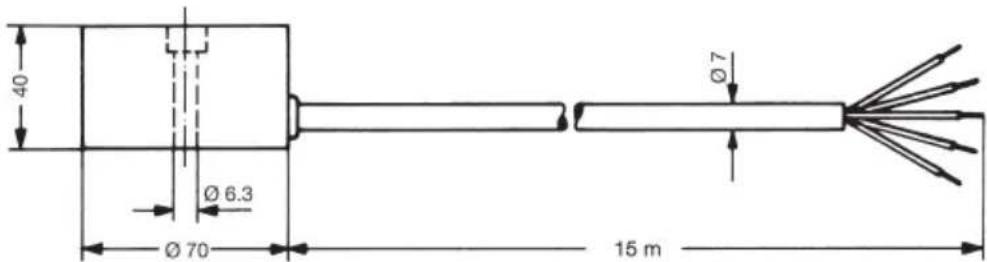
TFF 524 012
With FAG 524 111 sensor housing

The ice and snow sensor ESF 524 001 (5 core) is assembled as follows:

The snow and ice sensor must be mounted outside the heated area (see figs. 2 and 3 on page 18), or at least in a position not effected by the heating cable.
The sensor must be assembled so that it is directly exposed to the weather conditions (snow, rain, melt water (see figs. 4 and 5 on p. 19).
The position of the sensor should ideally be where moisture, snow or ice are still present, even when the area to be melted is almost fully cleared.
On inclines, always position the sensor at the lowest point, if necessary in the in the gully/gutter.
The sensor installation must be horizontal and level, so that any remaining moisture remains on the sensor surface.
The sensor must be at ground level or lower.
The use of small stone paving is not recommended, as the water seeps into the joints. The same applies to plastered surfaces. Sealed surfaces are ideal, such as tarmac, concrete, etc.
The sensor should not be positioned in a sheltered spot. Ensure that the sensor cannot be covered, for example by snow being cleared. Any foreign bodies or materials can impair the operation of the sensor.
Positions close to the outlets of heating / air conditioning systems should be avoided, as they are not suitable for sensor. Do not position the sensor close to, or on, building components which could heat up in the sun, causing the snow to melt faster.
The sensor's steel plate is set in the ground during the construction phase and the wooden mould is placed on top. The steel plate must be used to fix the sensor to guarantee the impermeability of the fixing hole. If the steel plate cannot be inserted due to constructional reasons, then a washer with a nut must be used. This is the only way in which the impermeability (press fit) in the bolt hole can be guaranteed. Note the red information tag!
A protective metal pipe must be installed flush to the wooden block for the connection lead. Seal the pipe ends to avoid any foreign bodies (tar, concrete, etc) clogging the protective tube.
After applying the top road surface, the wooden mould is removed and the sensor is fixed on the steel plate using the M 6 x 35 screw.
Any existing gaps must be filled with, for example, silicone, tar or mortar, depending on the composition of the surface. Max. casting temperature 80 °C ( 176 °F ).
The sensor's connection lead, default length 15 m (50 ft.), can, in accordance with VDE 0100, be extended up to a length of 50 m (164 ft.). With a cross section of 1.5mm ^2 (20 gauge) It is recommended that a numbered cable is used for the extension. This is very helpful, for example, when trying to locate faults during a malfunction.
The combined temperature and moisture sensors TFF 524 002 (4 core) are assembled as follows:
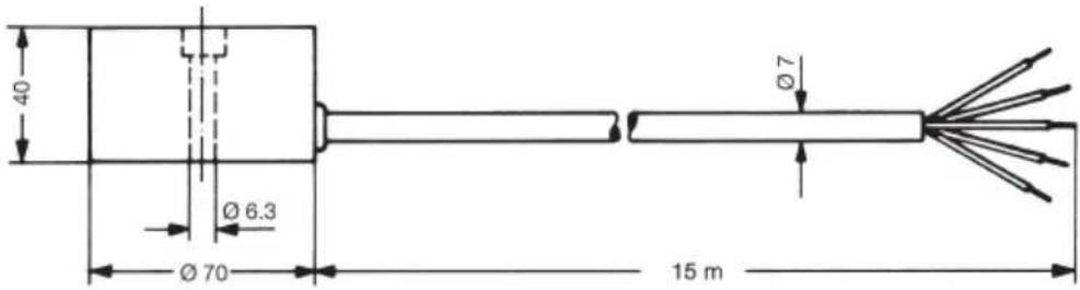
The combined sensor is installed inside the heated area (see figs. 2 and 3 on page 18), as it must monitor the ground temperature of the heated surface at all times (whether it is switched on or it is switched off).
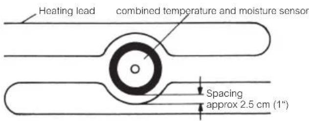
Heating cables must bypass the combined sensor by a minimum of 2.5 cm (1") (see fig. 6 on page 19).
Ensure that the heating cables running parallel to one another do not touch. The combined sensor must be fitted so that it is directly exposed to the weather conditions (snow, rain, melt water, etc) (see figs. 4 and 5 on p.19).
The combined sensor's steel plate is embedded in the ground during the construction phase and the wooden mould is placed on top. The steel plate must used to fix the sensor to guarantee the impermeability of the fixing hole. If the steel plate cannot be inserted due to constructional reasons, then a washer with a nut must be used. Only in this way can the impermeability (press fit) in the bolt hole be guaranteed. Note the red information tag!
A protective metal pipe must be installed flush to the wooden block for the connection lead. Seal the pipe ends to avoid any foreign bodies (tar, concrete, etc) clogging the protective tube.
After the applying the top road surface, the wooden block is removed and the sensor is fixed onto the steel plate using a M 6 x 35 screw.
Ensure that the combined sensor is fitted so that it cannot be covered over, for example by snow being cleared outside the heated area, and that no vehicles can drive over the combined sensor (for example, when entering or leaving a garage). Any foreign bodies or materials can impair the operation of the combined sensor.
Any existing gaps must be filled, for example with silicone, tar or mortar, depending on the composition of the surface. Max. casting temperature 80^ C ( 176^ F).
The combined sensor's connection lead, default length 15 m (50 ft.), can, in accordance with VDE 0100, be extended up to a length of 50 m 164 ft.). with a cross section of 1.5 mm ^2 (20 gauge).
It is recommended that a numbered cable is used for the extension. This is very helpful, for example, when trying to locate faults during a malfunction!
Determining where to fit the sensor/sensor housing is extremely important to ensure that the system works as well as it can.
The sensor must be fitted where the surface is most likely to become icy or frozen and stay this way for the longest time period.
The ESF 524 001/011 sensor (5-core connection cable) is fitted outside the heated surface.
The TFF 524 002/012 sensor (4 core connection cable) is fitted inside the heated surface.
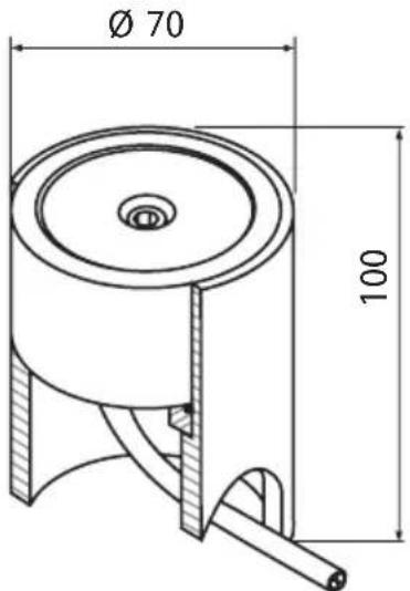
Installation of the sensor in the sensor housing FAG 524 111
Only the two sensor types ESF 524 011 and TFF 524 012 are suitable for installation in the sensor housing.
With both of these sensors the connecting cable exit is on the sensor bottom. Allowing the sensor to be replaced without having to lift the hard surface.

Installation of the sensor in the sensor housing FAG 524 111
A protective metal pipe running up to the sensor housing should be provided at the construction site for the connection cable.
If the sensor is to be run over an appropriate underlay (foundation or base plate) must be provided so that the sensor housing cannot be pushed into the soft ground.
Ensure that there is sufficient cable in the lower part of the sensor housing so that, when necessary, the sensor can easily be withdrawn from the housing.
Sensor housing in a concrete road surface
The sensor housing can be inserted in during the cementing process and the sensor inserted later.
Suitable measures must be taken to ensure that the concrete does not get into the housing.
The housing is to be installed so that the sensor surface is level with the ground surface. The sensor must not, under any circumstances, project from the ground surface. A level, horizontal, installation is fundamental, even with a sloping surface.
(Please refer to Assembly and operating instructions fig. 5 on page 19).
Fig.2
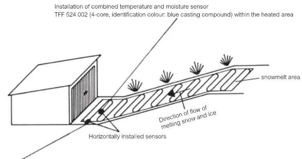
Installation of ice and snow sensor ESF 524 001 (5-core, identification colour: white casting compound) min. 20 cm (8") outside the heated area, or at least not influenced by the heating cable
Fig.3
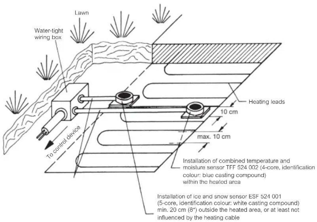
Fig.4

Fig.5

Fig.6
Ice and snow sensor ESD 524 003 (5-core)
The sensor is equipped with an NTC resistor for temperature measurement, a heating coil and two small metal pipes as moisture sensors.
Nominal voltage: 8 V-
Power consumption: 3 W
Surface temperature: Approx. 4°C (39°F)
Connecting lead: 5 x 0.25 mm²; 4 m PVC (5 x 22 gauge x 13 ft.)
Ambient temperature: -30 ... 80°C (-22 ... 176°F)
Sensor characteristics – sensor disconnected from control unit:
a) NTC – brown-yellow wires:
| °C | -15 | -10 | -5 | 0 | +5 | +10 | +15 | +20 | +25 | +30 | |
| °F | 5 | 14 | 21 | 32 | 43 | 50 | 61 | 68 | 79 | 86 | |
| R (K-Ohm) | 84.5 | 61.3 | 47 | 35.0 | 27 | 20.8 | 16 | 12.7 | 10 | 8.0 | |
b) Heat resistor – brown-green wires: 20 Ω
c) Moisture sensors – white-grey wires: ∞ Ω with dry sensor surface
Dimensions

TFD 524 004 (2 core) temperature sensor
The temperature sensor is composed of a cable with a compound-filled cap on top and inbuilt NTC resistor.
Connecting lead: 2 x 0.5 mm ^4 ; 4 m PVC (2 x 20 gauge x 13 ft.)
Ambient temperature: -30 ... 80°C (-22 ... 176°F)
Sensor characteristics – sensor disconnected from control unit:
a) NTC – brown-blue wires:
| °C | -15 | -10 | -5 | 0 | +5 | +10 | +15 | +20 | +25 | +30 | |||
| °F | 5 | 14 | 23 | 32 | 41 | 50 | 59 | 68 | 77 | 86 | |||
| R(K Ohm) | 11.7 | 9.1 | 7.2 | 5.7 | 4.6 | 3.7 | 3.0 | 3.4 | 2.0 | 1.6 | |||
Dimensions

The ESD 524 003 (5 core) ice and snow sensor is assembled as follows:

Where possible, assemble the ice and snow sensor near to the downpipe or waste pipe (lowest point) of the gutter, between the heating cables (do not let them come into contact with one another). The sensor is to be fitted so that it lies in the flow direction of the discharged water with the two metal pipes pointing upwards. The water running off is led to the sensor surface by the extruded fan. The fan can be cut to fit the existing conditions of the gutter
The sensor's connection lead, (default length 4 m, 13 ft.), can, in accordance with VDE 0100, be extended up to a length of 50 m (164 ft.), with a cross section of 1.5mm^2 (20 gauge). It is recommended that a numbered cable is used when extending the connection lead. This is helpful when trying to locate faults during a malfunction.
The temperature sensor TFD 524 004 (2 core) is fitted as follows:

natural_image
Simple line drawing of a coaxial cable with two leads (no text or symbols)The temperature sensor can be fitted outside, either on the gutter or near the gutter, but whichever one you choose, care must be taken to ensure that the sensor is protected from direct sunlight. The sensor must not be fitted above windows or in areas where heat accumulation can occur (roof sills, chimney, attic windows and the like).
The sensor's connection lead, (default length 4 m, 13 ft.), can, in accordance with the VDE 0100, be extended up to a length of 50 m (164 ft.), with a cross section of 1.5mm^2 (20 gauge). It is recommended that a numbered cable is used when extending the connection lead. This is helpful when locating faults during a malfunction.

Range setting
The RANGE menu item is called up with the MENU button and the lowest temperature limit is set with the Buttons – and + (EM 524 90) or the VALUE button (EM 524 89).
This temperature value specifies the lower operating temperature limit.
The upper working temperature is fixed at +6°C (43°F).
Up to this temperature limit the ice detector operates in normal mode (Heating ON, when the conditions for switching it on are satisfied). Below this temperature the ice detector will be in "Stand by" mode. Attention: The temperature range set here has priority over the base temperature.
Temperature setting
The TEMPERATURE menu item is called up with the MENU button and the desired temperature set with the Buttons – and + (EM 524 90) or the VALUE button (EM 524 89) and the value is saved by pressing ENTER.
An optimum temperature setting is +3°C (37°F).
Moisture setting:
The MOISTURE menu item is called up with the MENU button and the desired setting selected with the Buttons – and + (EM 524 90) or the VALUE button (EM 524 89). The value is saved by pressing ENTER.
An optimum moisture setting is 5. If there is a greater danger of pollution a setting of 6 or 7 should be made. If the heating switches off too early, even though there is still moisture present, you can prevent this by adjusting the moisture value to 3 or 2.
Ideally the setting should be assessed after 1-3 months of a winter season and the setting adjusted if necessary.
Base temperature setting
The BASE TEMPERATURE menu item is called up with the MENU button and the desired setting selected with the Buttons – and + (EM 524 90) or the VALUE button (EM 524 89). The value is saved by pressing ENTER. We recommend a setting of -5^ . The higher the set temperature, the higher the heating costs will be. This menu item is hidden in the roof application.
Please ensure that the 'Base' ground temperature set value is not lower than the lowest 'Range' ground temperature value set.
Operating modes
- Default settings:
| Menu Default Value Range | Remarks | |
| ZONE A A, B(only available on 2-zone Controller) | ||
| APPLICATION GROUND | 2 | |
| RANGE | -10°C | |
| TEMPERATURE | +3°C | |
| MOISTURE | 3 | |
| BASE TEMPERATURE OFF | ||
| AFTER RUN TIME 20 minutes | ||
| OPERATION | AUTOMATIC | |
| SENSOR HEATER ON | ||
| STANDARD PROGRAM ON | ||
| TEMP. UNIT User defined | 2 | |
| LANGUAGE User defined | 2 | |
2: During the initial installation the default value for the Language menu item is German, for the display menu item, °C, for the application menu item, Ground, after which these menu items no longer form part of the default settings.
In the default settings (standard program) the heating will be controlled by a combination of temperature and moisture level. The heating is switched on when the temperature falls below 3^ C ( 37^ F) and the moisture level exceeds 3. If the temperature falls below 3^ C ( 37^ F) the set after run time will be switched on. The heating will be switched off once the after run time has expired. If a moisture level of 3 is exceeded the set after run time will turn on and the heating will be switched off once this time has elapsed.
- Normal base temperature operation
| Menu | Value |
| BASE TEMPERATURE -5^ ( 23^ ) | |
The BASE TEMPERATURE menu item is set at -5^ ( 23^ ), the rest of the settings are as in point 1. The operation is as described in point 1. An added factor is that with a temperature beneath -5^ the heating will be switched on regardless of the moisture level and will stay switched on until the temperature goes above -5^ ( 23^ ). If the after run heating time is set, the heating will stay switched on till the time has elapsed.
3. Manual operation
The heating is switched on immediately and can only be switched off using this menu item. With manual operation the heating remains switched on even during alarms.
4. Operating without moisture influence
| Menu | Value |
| TEMPERATURE +3°C (37°F) | |
| MOISTURE | OFF |
If the MOISTURE menu item is set to OFF the ice detector will thermostatically control the heating. If the set temperature falls below the preset value the heating will be switched on and if exceeded the heating will be switched off depending on the after run time.
5. Monitoring the heated ground area when there is a sudden drop in temperature
This is an additional function and is only possible when the air temperature sensor TFD 524 004 is also connected (see connection diagram EM 524 90 using open space heating).
This air temperature sensor must be installed as well as the default sensors (Ice and snow sensor ESF 524 001/011 and combined temperature and moisture sensor TFF 524 002/012). The sensor TFD 524 004 should be fitted in a covered area approx. 2 – 3 m above ground level on the north side of the building, where it cannot be effected by the sun. The sensor connection is shown in the connection diagram.
If at temperatures below 7 °C ( 45 °F ) the temperature drops suddenly by several degrees, then the heating is switched on as a precaution for 1 hour as it is highly likely that it will rain and the temperature will decrease. Depending on the set temperature and moisture level the heating will stay switched on or will switch off after 1 hour.
Attention
The air temperature sensor must not be fitted over doors, windows or next to lights or spotlights.
Maintenance
Ensure that the surfaces of the ESF 524 001/011, TFF 524 002/012 and ESD 524 003 sensors are kept clean at all times. Ideally the gutter sensor would be cleaned a minimum of once a year, the ground sensors should be cleaned whenever there is any build up on the surface of the sensor.
If there is heavy snowfall, the sensors may need to be cleared of snow, to prevent an igloo-effect.
A regular inspection of the control unit is recommended so that any alarm messages can be recognised and rectified in a timely fashion. Only then will it be possible for the system to operate flawlessly.
Storage program
| Order no. | ||
| 1-zone ice detector control unit EM 524 89 0524 89 144 100 | ||
| 2-zone ice detector control unit EM 524 90 0524 90 144 100 | ||
| Sensor for open space heating: | ||
| Ice and snow sensor ESF 524 001 | (cable outlet on the side)15m connection lead | 0524 99 000 001 |
| Ice and snow sensor ESF 524 011 | (cable outlet underneath)15 m connection lead | 0524 99 000 011 |
| Combined temperature-and moisture sensor | TFF 524 002(cable outlet on the side)15 m connection lead | 0524 99 000 002 |
| Combined temperature-and moisture sensor | TFF 524 012(cable outlet underneath)15 m connection lead | 0524 99 000 012 |
| Sensor housing(can only be used withESF 524 011 and TFF 524 012 sensors) | FAG 524 111 0524 99 000 111 | |
| Sensor for gutter heating: | ||
| Ice and snow sensor ESD 524 003 | 4 m connection lead | 0524 99 000 003 |
| Temperature sensor TFD 524 004 | 4 m connection lead | 0524 99 000 004 |
Connection diagram 1:
Ice detector connection with ESF 524 001/011 and
TFF 524 002/012 sensors for open space heating.

Note:
Instead of the default 82 kΩ resistor a separate TFD 524 004 temperature sensor can be installed. This sensor is used to detect a drop in temperature and the air temperature thus measured is shown on the display.
Connection diagram 2:
Ice detector connection with ESD 524 003 and
TFD 524 004 sensors for gutter heating.

Note:
Instead of the default 82 kΩ resistor a separate TFD 524004 temperature sensor can be installed. This sensor is used to detect a drop in temperature and the air temperature thus measured is shown on the display.
Connection diagram 3:
Ice detector connection with ESF 524 001 and TFD 524 004 sensors.
Open space without second moisture measuring point.
It is possible to use only sensor ESF 524 001, along with temperature sensor TFD 524 004, for ground applications, although the position of sensor ESF 524 001 is critical and should be outside the heated area, or at least not influenced by the heating cable. All other points in 'Sensor Assembly' should also be considered. Temperature sensor TFD 524 004 must be installed in the ground within the heated area, but not touching the heating cable, to detect the base ground temperature, not air temperature.
More than one moisture measurement point, using sensors ESF 524 001 and TFF 524 002, will give the optimum results, especially with larger areas.

Connection diagram 1:
Ice detector connection with ESF 524 001/011 and
TFF 524 002/012 sensors for open space heating.
Note:
Instead of the default 82 kΩ resistor a separate TFD 524 004 temperature sensor can be installed. This sensor is used to detect a drop in temperature and the air temperature thus measured is shown on the display.
Connection diagram 2:
Ice detector connection with ESD 524 003 and
TFD 524 004 sensors for gutter heating.

Note:
Instead of the default 82 kΩ resistor a separate TFD 524004 temperature sensor can be installed. This sensor is used to detect a drop in temperature and the air temperature thus measured is shown on the display.
Connection diagram 3:
Ice detector connection with ESF 524 001 and TFD 524 004 sensors.
Open space without second moisture measuring point
It is possible to use only sensor ESF 524 001, along with temperature sensor TFD 524 004, for ground applications, although the position of sensor ESF 524 001 is critical and should be outside the heated area, or at least not influenced by the heating cable. All other points in „Sensor Assembly“ should also be considered. Temperature sensor TFD 524 004 must be installed in the ground within the heated area, but not touching the heating cable, to detect the ground temperature, not air temperature.
More than one moisture measurement point, using sensors ESF 524 001 and TFF 524 002, will give the optimum results, especially with larger areas.

Technical data
| Type EM 52489 | EM 524 90 |
| Part no. 0524 89 144 100 | 0524 90 144 100 |
| Operating voltage: AC 230 V ±10 %, 50/60 Hz |
| Power consumption: ≤ 15 VA | ≤ 25 VA |
| Ambient temperature: -20 ... + 50°C (-4 ... 122°F) |
| Storage temperature: -20 ... + 70°C (-4 ... 158°F) |
| Desired value range | |
| Range: Lower temperature limit -5 ... -20°C (3 ... -4°F) and OFF | |
| Temperature: 0°C ... +6°C | |
| Base temperature: -15 ... -1°C (5 ... 30°F) and Off | |
| Moisture: 1 (sensitive)... 8 (insensitive) and Off | |
| After run time: 10 min ... 24 hrs and Off | |
| Operation: Automatic and Permanent | |
| Sensor Heater: Automatic and On | |
| Language: | German, English, French, Finnish, Swedish, Czech, Dutch, Hungarian, Turkish, Polish, Italian |
| Outputs | ||
| Heater On/Off: | 1 relay | 2 relays, One normally open | Both are normally open per zone |
| Switching capacity: | AC 250 V, 16 A cos φ= 1; 4 A cos φ = 0.6 | |
| Alarm On/Off: | Relays, 1 c/o contact | |
| Switching capacity: | AC 250 V, 2 A cos φ = 1; 0.8 A cos φ = 0.6 | |
| Inputs | |
| Ice and snow sensor: | Type ESF 524 001/011 for open spaces |
| Type ESD 524 003 for gutters | |
| Ground temperature sensor: | TFF 524 002/012 type for open spaces |
| TFD 524 004 type for gutters | |
| Air temperature sensor: | Type TFD 524 004 |
Display
| LCD Display: 2-row 16-digit |
| Temperatures: -45 ... + 78°C (-49 ... 172°F) |
| Moisture: 0 ... 9 |
| Heating: ON, OFF |
| Fault status: Fault sensor |
| Parameters: Values and selection |
| LED indication: No | 2 LEDs for the dialogue displaying |
Below 0^ C ( 32^ F) the correct reading of the LCD display cannot be guaranteed, the operation of the equipment, however, will not be affected by this.
Controls
| Input buttons: 4 piece (MENU / + / - / ENTER) for EM 524 90 |
| 3 piece (MENU / VALUE / ENTER) for EM 524 89 |
General details
| Complies with: DIN EN 60 730 T. 1 and T. 2-9 | |
| Protection class: II is achieved by observing appropriate installation measures | |
| Protection type: | IP 20 EN 60 529 |
| Shockproof: in accordance with VBG 4 | |
| Overvoltage category | III |
| Software class | A |
| Rated impulse voltage | 4kV |
| Pollution degree | 2 |
| Ball pressure test temperature | 75 ± 2 °C |
| Voltage and Current for the for purposes of interference measurements | 230 V; 0,1 A |
| Nominal insulation voltage: | 250 V |
| Assembly: | Snap-on mount on DIN EN 50022-35 S |
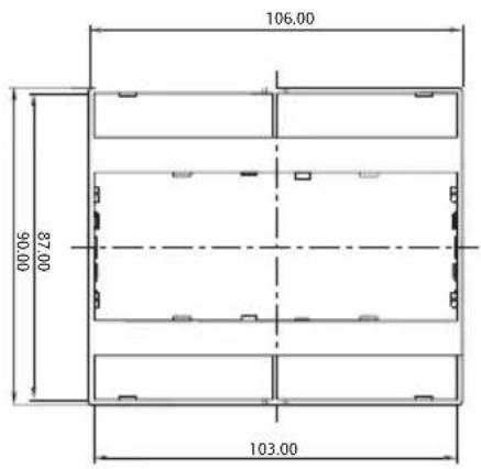
| Housing dimensions: (45 cut out) | 106 x 90 58 mm | 159 x 90 mm (45 cut out) |
| Housing material: | PC; UL94-V0 |
| Weight: without sensor and packaging | approx. 480 g | approx. 780 g |
EM 524 89 (1-zone controller) EM 524 90 (2-zone controller)

Brief operating instructions for ice detectors EM 524 89 and EM 524 90 for open space and gutter heating
Application:
The ice detector is used for the fully automatic electric heating of open spaces, garage drives, stairs, ramps, flat rooves and gutters. Unlike manually-controlled (touch dependent) or thermostatically-controlled (temperature dependent only) systems, the heating will only be switched on if there is a danger of slippery conditions such as snow, ice or sleet and will, naturally, be switched off after thawing. This ensures energy savings of up to 80% compared with thermostatically-controlled systems.
Factory Setting:
These are the factory settings and will appear when first powering up the Controller. The user should set these to the desired value at this point. Resetting the Controller to the 'STANDARD PROGRAM' will not effect these settings.
Menu Delivery setting Range
| TEMP. UNIT °C °C, °F | ||
| LANGUAGE | DEUTSCH | DEUTSCH, ENGLISH, FRANCAISE, SUOMI, SVENSKA, CESKY, DUTCH, MAGYAR, TURKCE, POLSKI, ITALIANO |
Operation:
For problem free operation a default program is saved. The ice detector works on the basis of this default program after installation.
These settings can be recalled at any time using the STANDARD PROGRAM menu item.
Default program:
Menu Default value Range Remarks
| ZONE A A, B(only available on 2-zone Controller) | |||
| APPLICATION GROUND GROUND, ROOF, OFF 2 | |||
| RANGE -10°C (14°F) -5 ... -20°C (23 ... -4°F), OFF | |||
| TEMPERATURE +3°C (37°F) 0 ... 6°C (32 ... 43°F) | |||
| MOISTURE 3 1-8, OFF | |||
| BASE TEMPERATURE OFF | ...15 ... -1°C (5 ... 30°F), OFF | 1 | |
| AFTER RUN TIME | 20 M | 10 M ... 24 H, OFF | |
| OPERATION | AUTOMATIC | AUTOMATIC, PERMANENT | |
| SENSOR HEATER | ON | AUTOMATIC, ON | |
| STANDARD PROGRAM | ON | ON, OFF | |
| TEMP. UNIT | User defined | °C, °F | 2 |
| LANGUAGE | User defined | DEUTSCH, ENGLISH, FRANCAISE, SUOMI, SVENSKA, CESKY, DUTCH, MAGYAR, TURKCE, POLSKI, ITALIANO | 2 |
| COUNTER | xxxxxHyyM | ||
1: These menu items only appear in the GROUND application
2: During the initial installation the default value for the Language menu item is German, for the display menu item, °C, for the application menu item, ground, after which these menu items no longer form part of the default settings.
Use the MENU button to select all of the menu items in order. The selected menu item is shown in the top display line. The bottom display line shows the current value for this menu item and "ACTIVE".
For example: TEMPERATURE 3 °C ACTIVE
The desired value can be changed with the buttons - and + (EM 524 90) or the VALUE button (EM 524 89). The current value is marked with the word ACTIVE.
If another value is selected only this will show in the bottom line.
To select this value as the setting, press ENTER. The new value will be applied to the control program and displayed with the word ACTIVE.
If you do not press ENTER or, if after you have selected the new desired value with the Buttons – and + (EM 524 90) or the VALUE button (EM 524 89), another menu item is selected with the MENU button, the new value will not be applied. If no button is pushed for 20 seconds the display changes to "Measured value" mode. The mode changes between display of the measured temperatures and the moisture and heating at 3 second intervals. If the supplied resistor is connected instead of the air temperature sensor, the value for the air temperature is not shown.
For example: GROUND -11^ AIR -11^
| and | |
| MOISTURE | 7 |
| HEATING | ON |
Should there be an alarm, the display starts flashing at one second intervals. The alarm relay closing contact (terminals 11 and 12) closes. The word "ALARM" appears on the top line. At the same time, the cause of the alarm is displayed on the bottom line. The measured values continue to be displayed:
For example: ALARM TEMP SHORT CIRCUIT
Here the display also changes to menu mode when the button is pushed, but in this instance the display flashes, to continue drawing attention to the alarm. During an alarm the menu items can be selected, for example, leaving the heating system switched on in manual mode. If no button is pushed for 20 seconds the alarm will be displayed again.

This product should not be disposed of with household waste.
Please recycle the products where facilities for electronic waste exist.
Check with your local authorities for recycling advice.
EBERLE
In accordance with our continuous improvement procedures, we reserve the right to change design features and specifications without prior notification. The data contained in this document is for guidance only.
EBERLE Controls GmbH accepts no liability for any consequential losses, injury or damage resulting from the use of this document or the information contained within.




- operating instructions Ice detector
- EM 524 89
- EM 524 90
- Contents
- WARNING:
- Note!
- Instructions
- General description 2-zone EM 524 90 and 1-zone EM 524 89
- 1-zone controller
- 2-zone controller
- Controls
- Note 1\*:
- Menu mode
- For example: TEMPERATURE
- Remarks:
- Menu items
- Operating
- Design
- Attention
- Dimensions
- Combined temperature and moisture sensor TFF 524 002 or TFF 524 012 (4 core)
- The ice and snow sensor ESF 524 001 (5 core) is assembled as follows:
- The combined temperature and moisture sensors TFF 524 002 (4 core) are assembled as follows:
- Installation of the sensor in the sensor housing FAG 524 111
- Sensor housing in a concrete road surface
- Ice and snow sensor ESD 524 003 (5-core)
- TFD 524 004 (2 core) temperature sensor
- The ESD 524 003 (5 core) ice and snow sensor is assembled as follows:
- The temperature sensor TFD 524 004 (2 core) is fitted as follows:
- Range setting
- Temperature setting
- Moisture setting:
- Base temperature setting
- Operating modes
- Manual operation
- Operating without moisture influence
- Monitoring the heated ground area when there is a sudden drop in temperature
- Maintenance
- Connection diagram 1:
- Note:
- Connection diagram 2:
- Connection diagram 3:
- Brief operating instructions for ice detectors EM 524 89 and EM 524 90 for open space and gutter heating
- Application:
- Factory Setting:
- Operation:
- Default program:
- EBERLE
Brand : Eberle
Model : EM 524 90
Category : Detector