SFAB-1000U-WQ10-2SV-M12 - Measurement Festo - Free user manual and instructions
Find the device manual for free SFAB-1000U-WQ10-2SV-M12 Festo in PDF.


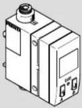
| Product Type | Flow Sensor for Compressed Air |
| Model | SFAB-1000U-WQ10-2SV-M12 |
| Brand | Festo |
| Measuring Range | 0.5...1000 L/min (adjustable) |
| Output Signal | 0...10 V DC (analog) + 2x switching outputs (PNP/NPN) |
| Process Connection | G1/4 female thread |
| Electrical Connection | M12x1, 5-pin male connector |
| Supply Voltage | 24 V DC (10...30 V DC) |
| Current Consumption | < 100 mA |
| Accuracy | ±3 % of full scale |
| Repeatability | ±0.5 % |
| Pressure Range | 0...10 bar relative |
| Medium | Compressed air, inert gases |
| Ambient Temperature | -10...60 °C |
| Medium Temperature | -10...50 °C |
| Protection Class | IP65 (with correct mating connector) |
| Housing Material | Polyamide (PA) with aluminum cover |
| Dimensions (L x W x H) | 94 mm x 30 mm x 50 mm |
| Weight | Approx. 120 g |
| Display | None (setting via teach-in) |
| Functions | Flow measurement, monitoring, 2 switch outputs with adjustable setpoints |
| Maintenance and Cleaning | No special maintenance required; clean with dry cloth if needed |
| Safety | Observe pressure and temperature limits; install according to manual |
| Spare Parts and Repairability | Device is sealed and not repairable; replace if faulty |
| General Information | For indoor use only; do not use with liquids |
Frequently Asked Questions - SFAB-1000U-WQ10-2SV-M12 Festo
User questions about SFAB-1000U-WQ10-2SV-M12 Festo
0 question about this device. Answer the ones you know or ask your own.
Ask a new question about this device
Download the instructions for your Measurement in PDF format for free! Find your manual SFAB-1000U-WQ10-2SV-M12 - Festo and take your electronic device back in hand. On this page are published all the documents necessary for the use of your device. SFAB-1000U-WQ10-2SV-M12 by Festo.
USER MANUAL SFAB-1000U-WQ10-2SV-M12 Festo
Operating instructions
8156241
2021-05d
[8156243]
FESTO
Festo SE & Co. KG
Ruiter Straße 82
73734 Esslingen
Deutschland
+49 711 347-0
www.festo.com
8156241
Translation of the original instructions
© 2021 all rights reserved to Festo SE & Co. KG
1 About this document
1.1 Applicable Documents
□1
All available documents for the product → www.festo.com/sp.
2 Safety
2.1 General safety instructions
-Only use the product in original status without unauthorised modifications.
-Only use the product if it is in perfect technical condition.
- Observe labelling on the product.
-Condensation, oil mist, foreign matter and other contaminants in the compressed air can damage the product. Only use media in accordance with the specifications Technical data.
-This product can generate high frequency malfunctions, which may make it necessary to implement interference suppression measures in residential areas.
2.2 Intended use
The SFAB is designed to monitor changes in the flow rate and air consumption of gaseous media in piping systems or terminals in industry.
2.3 Training of qualified personnel
Work on the product may only be carried out by qualified personnel who can evaluate the work and detect dangers. The qualified personnel have skills and experience in dealing with electropneumatic (open-loop) control technology.
2.4 Range of application and approvals
Certain configurations of the product have been certified by Underwriters Laboratories Inc. (UL) for the USA and Canada. These configurations bear the following mark:

Fig.1
UL Recognized Component Mark for Canada and the United States. Only for connection to an NEC Class 2 supply. Raccorder Uniquement a un circuit de Classe 2.
i
Observe the following if the UL requirements are to be complied with in your application:
- Regulations for complying with the UL certification can be found in the separate UL-specific special documentation. The technical data listed there take priority.
- The technical data in this documentation may show values deviating from this.
3 Additional information
-Contact the regional Festo contact if you have technical problems
→ www.festo.com.
-Accessories and spare parts → www.festo.com/catalogue.
4
Product overview
4.1 Product design
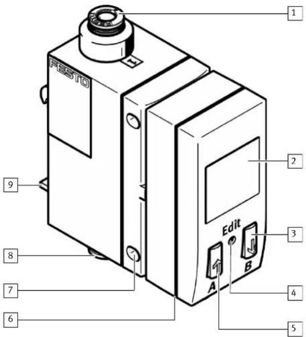
Fig. 2: SFAB
1 Supply port 1
2 Display
3 B pushbutton
4 Edit button
5 A pushbutton
6 Plug for the electrical connection (M12)
7 Hole for plate mounting
8 Supply port 2
9 Mounting slide for H-rail and wall mounting (rear)
4.2 Functional principle
The SFAB uses a thermal measurement method. Here, the amount of heat drawn from a heated surface of the sensor by the medium flowing past it is calculated. Through the amount of heat removed, the flow rate or accumulated air consumption is determined and shown on the display. The connection to higher-level systems is implemented through 2 binary outputs (Out A/OutB) and one analogue output. Switching points can be defined for both binary outputs. Switching points for both binary outputs are possible for flow rate measurement, a consumption switching pulse for output A (OutA) is possible for cumulative air consumption measurement. The combination of cumulative air consumption measurement (OutA) and flow rate measurement (OutB) is possible. The flow value is output via the analogue output.
5 Assembly
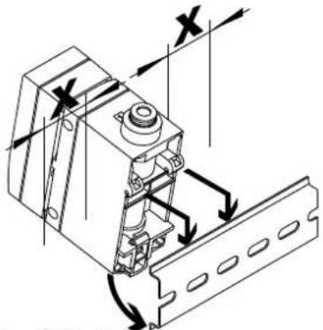
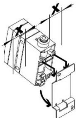
5.1 H-rail (manifold assembly)
- Maintain lateral distance x = 10 mm to earthed surfaces.
natural_image
Technical line drawing of a mechanical assembly with directional arrows indicating motion (no text or symbols)- Hang SFAB in H-rail.
- Press SFAB in the direction of the arrow.
SFAB snaps into place.
5.2 Wall mounting
- Maintain lateral distance x = mm to earthed surfaces.
natural_image
Mechanical assembly diagram showing a piston and connecting rod with directional arrows (no text or labels)- Fasten the adapter plate with 2 screws M3.
- Hang the SFAB in the adapter plate.
- Press SFAB in the direction of the arrow.
SFAB snaps into place.
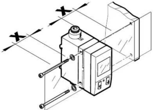
5.3 Plate mounting
- Maintain lateral distance x = mm to earthed surfaces.
natural_image
Technical line drawing of a mechanical device with alignment lines and no visible text or symbols- Fasten SFAB with washers and 2 screws M4.
- Tightening torque: 1 Nm
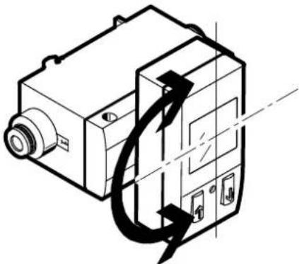
5.4 Rotate display
The display can be rotated in 90° steps. The turning range is limited to approx. 270° by a stop.
natural_image
Technical line drawing of a mechanical device with directional arrows indicating motion (no text or symbols)Fig. 3: Rotate display
6 Installation
6.1 Pneumatic installation
- Mount the hoses to port 1 and port 2 (flow direction marked on the product).
If the tubing is incorrect, the measured values are shown flashing on the display.
6.2 Electrical installation
WARNING
Risk of injury due to electric shock.
- For the electrical power supply, use only PELV circuits in accordance with IEC 60204-1/EN 60204-1 (Protective Extra-Low Voltage, PELV).
- Observe the general requirements of IEC 60204-1/EN 60204-1 for PELV circuits.
-
Only use voltage sources that ensure a reliable electric separation from the mains network in accordance with IEC 60204-1/EN 60204-1.
-
Use signal lines that are shorter than 10 m.
-
Configure binary outputs according to the wiring.
-Tightening torque for the union nut at the plug: max. 0.5 Nm
| Pin Wire colour | 1) | Allocation Plug | |
| 1 Brown (BN) Operating voltage | +24 V DC | M12, 5-pin23+++154 | |
| 2 White (WH) Binary output B (OutB) | |||
| 3 Blue (BU) 0 V | |||
| 4 Black (BK) Binary output A (OutA) | |||
| 5 Grey (GY) Analogue output C | |||
1) When using the connecting cable from the accessories,
Tab. 1: Pin allocation
Circuit diagrams
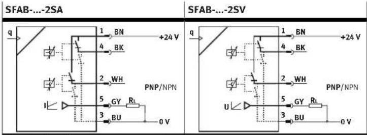
flowchart
graph TD
    subgraph SFAB-...-2SA
        A["1"] --> B["BN"]
        C["4"] --> D["BK"]
        E["2"] --> F["WH"]
        G["5"] --> H["GY"]
        I["3"] --> J["BU"]
        K["0 V"] --> L["PNP/NPN"]
    end
    subgraph SFAB-...-2SV
        M["1"] --> N["BN"]
        O["4"] --> P["BK"]
        Q["2"] --> R["WH"]
        S["5"] --> T["GY"]
        U["3"] --> V["BU"]
        W["0 V"] --> X["PNP/NPN"]
    end
Tab. 2: Circuit diagrams
7 Commissioning
- Switch on operating voltage.
SFAB is in RUN mode.
-
Define the switching behaviour of the binary outputs.
-
For flow measurement [FLW]: switching points [SP] and hysteresis [Hy]
-For cumulative air consumption measurement [ConS] with OutA only: consumption switching impulse [CI]
7.1 Switching outputs
7.1.1 Switching functions
7.1.1.1 Threshold value comparator in the flow rate measurement for OutA or OutB
| Function | NO (normally open) | NC (normally closed) |
| Switching function: - 1 switching point (SP) TEACH mode: - 2 teach points (TP1, TP2) |
Tab. 3: Threshold value comparator
7.1.1.2 Window comparator in the flow rate measurement for OutA or OutB
| Function | NO (normally open) | NC (normally closed) |
| Switching function: - 2 switching points (SP.Lo, SP.Hi) | OUT 1 HY 0 TP1=SP.Lo TP2=SP.Hi | OUT 1 HY 0 TP1=SP.Lo TP2=SP.Hi |
| TEACH mode: - 2 teach points (TP1, TP2) - TP1 = SP.Lo, TP2 = SP.Hi |
1) SP.Lo = smaller value, SP.Hi = larger value, independent of the teach sequence
Tab. 4: Window comparator
7.1.1.3 Consumption switching pulses [CI] for cumulative air consumption measurement for OutB
A threshold value for air consumption can be set with the consumption switching impulse [CI]. If the set threshold value is reached, a switching impulse is emitted at the output Out A for 100 ms. With each switching impulse, measurement of the air consumption is started again.
![Festo SFAB-1000U-WQ10-2SV-M12 - Consumption switching pulses [CI] for cumulative air consumption measurement for OutB - 1](/content/2026/05/908894/images/661ed47d754d006d9d97f34b22da3364bc413234b489b92429be8f8aa19d8fff.jpg)
line
| Signal | Time (ms) | | :--- | :--- | | Setting NO (N/O normally open) contact | 0 | | Setting NO (N/O normally open) contact | 100 ms | | Setting NO (N/O normally open) contact | 100 ms | | Setting NC (N/C normally closed) contact | 0 | | Setting NC (N/C normally closed) contact | 100 ms | | Setting NC (N/C normally closed) contact | 100 ms |Tab. 5: Consumption switching pulses
7.2 Display components
| Symbol Description | |
| OutA/OutB Switching output | A/switching output B |
| Lock Security code active ( blocked against unauthorised programming) | |
| Run Accumulated air consumption measurement is active in RECORDER mode | |
| Option Sensor is set to a standard condition that differs from the factory setting | |
| Stop Air consumption measurement stopped | |
| Switching output set/not set | |
| Threshold value comparator | |
| Window comparator | |
| ConS | Air consumption switching mode (consumption - only for OutA) |
| CI | Pulse for accumulated air consumption (consumption impulse) |
| SP | Switching point |
| SPLo | Lower switching point (switching point - low) |
| SPHi | Upper switching point (switching point - high) |
| HY | Hysteresis |
| no | N/O contact (normally open) |
| nc | N/C contact (normally closed) |
| FLLU | Switching mode flow rate (flow - only for OutA) |
| FLo | Minimum flow rate (flow low) |
| FH, | Maximum flow rate (flow high) |
| SPEC | Special menu |
| AnAF | Analogue filter |
| dIGF | Digital filter |
| rOn | Display red with switching status ON and/or logic 1 |
| rOFF | Display red with switching status OFF and/or logic 0 |
| PnP | Positive switch output |
| nPn | Zero switch output |
| Segments are lighted: graphic display of the current measured value related to the maximum measured value of the measuring range | |
| Running light (1 segment): air consumption measurement for OutA or RECORDER mode active | |
| 3 segments flash: hysteresis value is displayed | |
| 1 segment flashes:-Segment 6: switching point SP or SP.Lo is displayed-Segment 8: switching point SP.Hi is displayed-Segment 1: min. flow rate (F.Lo) is displayed-Segment 10: max. flow rate (F.Hi) is displayed | |
Tab. 6: Symbols on the display
7.3 Preparing commissioning
The product in basic status is in RUN mode. The current measurement values are displayed. The basic status can be reached from other modes by:
-Pressing Edit button for 3 seconds
- Expiration of monitoring time, timeout
- Switch on operating voltage.
The SFAB is in RUN mode.
- Check the SFAB settings → 7.6 SHOW mode.
7.4 Symbols for representing the menu structure
| Symbol Description | ||
 | Automatic return to the basic status (RUN mode) when the monitoring time has expired (here 80 seconds) | |
| In order to return manually to the basic status (RUN mode), press the EDIT button for 3 seconds. | ||
 | Generate flow rate (for teaching the measured value - here Flow 1) | |
| [TB2K] | The symbol on the display flashes (here OutB) | |
| Security code active (lock - blocked against unauthorised programming) | ||
| Security code inactive (lock) | ||
| Press key (here A key). | ||
 | Press A key or B key. SFAB switches to the setting indicated by the arrows. | |
 | Press A and B keys simultaneously. | |
| Press key (here A key) and EDIT button simultaneously. | ||
| Press A key or B key to set the desired value. | ||
| Display for a value or switching point. Value can be set. | ||
| Symbol Description | |
| EDIT | Press the Edit button. |
| Branching in the menu |
Tab. 7
7.5 RUN mode
The following values are displayed in RUN mode:
-Measurement values for the flow rate (in l/min, scfm or l/h)
-Measurement values for air consumption (in m³, scf or l)
-Signal states of the switching outputs OutA, OutB (set, not set)
i
If the measured value display flashes, one of the following errors has occurred:
• Measured value outside the permissible measuring range
- Incorrect tubing 6.1 Pneumatic installation
7.6 SHOW mode
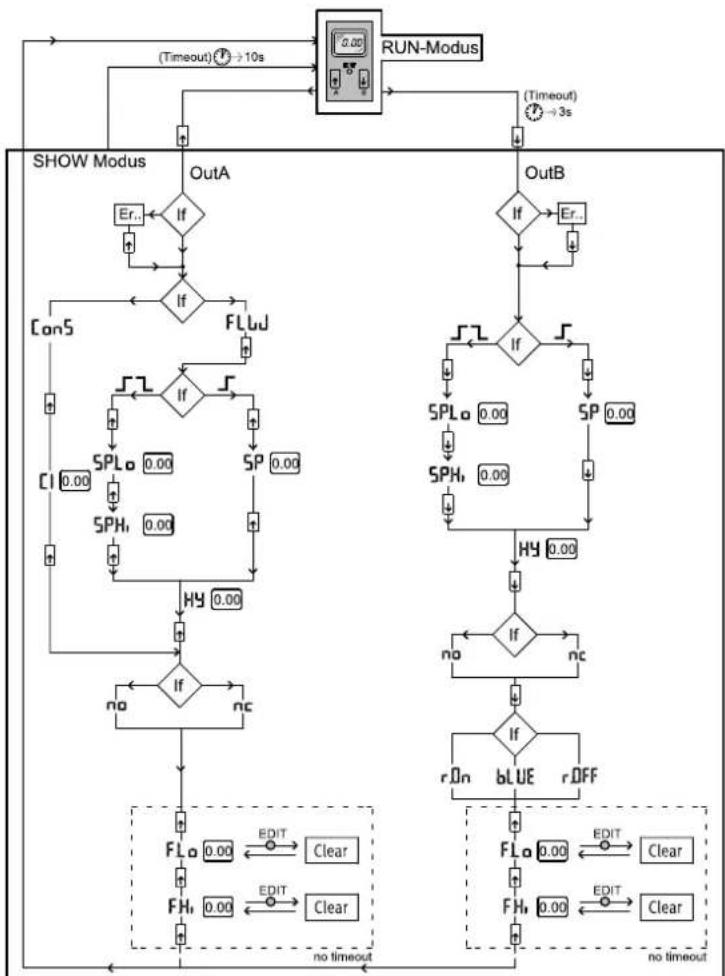
In SHOW mode, the current settings for the switching outputs Out A and Out B are displayed.
The SFAB must be in RUN mode.
- To start the SHOW mode for the respective switching output, press the A key (OutA) or B key (OutB).
i
If there are errors, the corresponding error numbers are displayed first after pressing the A / B pushbutton.
- To display the settings one by one, press the A/B pushbutton repeatedly. When all settings have been displayed, the SFAB goes back into RUN mode when the A pushbutton / B pushbutton are pressed again and displays the current measurement value for the corresponding output. Thus, the SHOW mode can also be used to switch the display, e. g. to switch between the displayed measured values for a combination of air consumption measurement and flow rate measurement.
The following settings will be displayed for outA:
-With flow measurement [FLW]:
- Switching function [threshold value or window comparator]
-Switching point [SP], Switching points [SP.Lo] and [SP.Hi] - Hysteresis [Hy]
-Switching element function [no/nc] (N/O contact/N/C contact)
-Minimum flow rate [F.Lo] (flow low) - Maximum flow rate [F.Hi] (flow high)
To delete the minimum or maximum value, press the EDIT button.
- For air consumption measurement [ConS]:
Air consumption switching impulse [CI]
-Switching element function [no/nc] (N/O contact/N/C contact)
- Minimum value flow rate [F.Lo]
-Maximum value flow rate [F.Hi]
To delete the minimum or maximum value, press the EDIT button.
The following settings will be displayed for OutB:
-Switching function [threshold value or window comparator]
- Switching point [SP], Switching points [SP.Lo] and [SP.Hi]
-Hysteresis [Hy]
-Switching element function [no/nc] (N/O contact/N/C contact)
Status colour change [bLUE/rON/rOFF]
-Minimum value flow rate [F.Lo]
- Maximum value flow rate [F.Hi]
To delete the minimum or maximum value, press the EDIT button.
flowchart
```mermaid
graph TD
    A["Run-Modus"] --> B["(Timeout) 0s → 10s"]
    B --> C{Decision}
    C -->|Yes| D["FLUJ"]
    C -->|No| E["SPH"]
    D --> F{Decision}
    F -->|Yes| G["FLa 0.00"]
    F -->|No| H["FLb 0.00"]
    G --> I["Clear"]
    H --> J["Clear"]
    K["Show Modus"] --> L["OutA"]
    K --> M["OutB"]
    L --> N{Decision}
    N -->|Yes| O["FLuJ"]
    N -->|No| P["FLa 0.00"]
    O --> Q["SPH 0.00"]
    Q --> R["SPH 0.00"]
    R --> S["SPL 0.00"]
    S --> T["SPL 0.00"]
    T --> U["SPH 0.00"]
    U --> V["SPL 0.00"]
    V --> W["SPL 0.00"]
    W --> X["SPH 0.00"]
    X --> Y["SPL 0.00"]
    Y --> Z["SPL 0.00"]
    Z --> AA["SPH 0.00"]
    AA --> AB["SPL 0.00"]
    AB --> AC["SPL 0.00"]
    AC --> AD["SPH 0.00"]
    AD --> AE["SPL 0.00"]
    AE --> AF["SPL 0.00"]
    AF --> AG["SPH 0.00"]
    AG --> AH["SPL 0.00"]
    AH --> AI["SPL 0.00"]
    AI --> AJ["SPH 0.00"]
    AJ --> AK["SPL 0.00"]
    AK --> AL["SPL 0.00"]
    AL --> AM["SPH 0.00"]
    AM --> AN["SPL 0.00"]
    AN --> AO["SPL 0.00"]
    AO --> AP["SPH 0.00"]
    AP --> AQ["SPL 0.00"]
    AQ --> AR["SPL 0.00"]
    AR --> AS["SPH 0.00"]
    AS --> AT["SPL 0.00"]
    AT --> AU["SPL 0.00"]
    AU --> AV["SPH 0.00"]
    AV --> AW["SPL 0.00"]
    AW --> AX["SPL 0.00"]
    AX --> AY["SPH 0.00"]
    AY --> AZ["SPL 0.00"]
    AZ --> BA["SPL 0.00"]
    BA --> BB["SPH 0.00"]
    BB --> BC["SPL 0.00"]
    BC --> BD["SPL 0.00"]
    BD --> BE["SPH 0.00"]
    BE --> BF["SPL 0.00"]
    BF --> BG["SPL 0.00"]
    BG --> BH["SPH 0.00"]
    BH --> BI["SPL 0.00"]
    BI --> BJ["SPL 0.00"]
    BJ --> BK["SPH 0.00"]
    BK --> BL["SPL 0.00"]
    BL --> BM["SPL 0.00"]
    BM --> BN["SPH 0.00"]
    BN --> BO["SPL 0.00"]
    BO --> BP["SPL 0.00"]
    BP --> BQ["SPH 0.00"]
    BQ --> BR["SPL 0.00"]
    BR --> BS["SPL 0.00"]
    BS --> BT["SPH 0.00"]
    BT --> BU["SPL 0.00"]
    BU --> BV["SPL 0.00"]
    BV --> BW["SPH 0.00"]
    BW --> BX["SPL 0.00"]
    BX --> BY["SPL 0.00"]
    BY --> BZ["SPH 0.00"]
    BZ --> CA["SPL 0.00"]
    CA --> CB["SPL 0.00"]
    CB --> CC["SPH 0.00"]
    CC --> CD["SPL 0.00"]
    CD --> CE["SPL 0.00"]
    CE --> CF["SPH 0.00"]
    CF --> CG["SPL 0.00"]
    CG --> CH["SPL 0.00"]
    CH --> CI["SPH 0.00"]
    CI --> CJ["SPL 0.00"]
    CJ --> CK["SPL 0.0O"]
    CK --> CL["SPH 1.5x16=12=14=16=18=16=18=18=18=18=18=18=18=18=18=18=18=18=18=18=18=18=18=18=18=18=18=18=18=18=18=18=18=18=18=18=18=18=18=18<br>    subgraph Show Modus<br>        L<br>        M<br>        N<br>        O<br>        P<br>        Q<br>        R<br>        S<br>        T<br>        U<br>        V<br>        W<br>        X<br>        Y<br>        Z<br>        AA<br>        AB<br>        AC<br>        AD<br>        AE<br>        AF<br>        AG<br>        AH<br>        AI<br>        AJ<br>        AK<br>        AL<br>        AM<br>        AN<br>        AO<br>        AP<br>        AQ<br>        AR<br>        AS<br>        AT<br>        AU<br>        AV<br>        AW<br>        AX<br>        AY<br>        AZ<br>        BA<br>        BB<br>        BC<br>        BD<br>        BE<br>        BF<br>        BG<br>        BH<br>        BI<br>        BJ<br>        BK<br>        BL<br>        BM<br>        BN<br>        BO<br>        BP<br>        BPB<br>        BA<br>        BB<br>        BC<br>        BC<br>        BC<br>        BC<br>        BC<br>        BC<br>        BC<br>        BC<br>        BC<br>        BC<br>        BC<br>        BC<br>        BC<br>        BC<br>        BC<br>        BC<br>        BC<br>        BC<br>        BC<br>        BC<br>        BC<br>        BC<br>        BC<br>        BC<br>        BC<br>        BC<br>        BC<br>        BC<br>        BC<br>        BC<br>        BC<br>        BC<br>        BC<br>        BC<br><br>    subgraph Show Modus<br>        L<br>        M<br>        N<br>        O<br>        P<br>        Q<br>        R<br>        S<br>        T<br>        U<br>        V<br>        W<br>        X<br>        Y<br>        Z<br>        AB<br>        AC<br>        AD<br>        AE<br>        AF<br>        AG<br>        AH<br>        AI<br>        AJ<br>        AK<br>        AL<br>        ALb,<br>        ALc,<br>      end<br><br>    subgraph Show Modus<br>        L<br>        M<br>        N<br>        O<br>        P<br>        Q<br>        R<br>        S<br>        T<br>        U<br>        V<br>        W<br>        X<br>        Y<br>        Z<br>        AB<br>        AC<br>        AD<br>      end<br><br>    subgraph Show Modus<br>        L<br>        M<br>        N<br>        O<br>        P<br>        Q<br>        R<br>        S<br>        T<br>        U<br>        V<br>        W<br>        X<br>       //no timeout; //no timeout; //no timeout; //no timeout; //no timeout; //no timeout; //no timeout; //no timeout; //no timeout; //no timeout; //no timeout; //no timeout; //no timeout; //no timeout; //no timeout; //no timeout; //no timeout; //no timeout; //no timeout; //no timeout; //no timeout; //no timeout; //no timeout; //no timeout; //no timeout; //no timeout;<br>    end<br><br>    subgraph Show Modus:<br>        L1((Ex))<br>            L2((Ex))<br>            L3((Ex))<br>            L4((Ex))<br>            L5((Ex))<br>            L6((Ex))<br>            L7((Ex))<br>            L8((Ex))<br>            L9((Ex))<br>            L1((Ex))<br>            L1a((Ex))<br>            L1b((Ex))<br>            L1c((Ex))<br>            L1d((Ex))<br>            L1e((Ex))<br>            L1f((Ex))<br>            L2((Ex))<br>            L2a((Ex))<br>            L2b((Ex))<br>            L2c((Ex))<br>            L2d((Ex))<br>            L2e((Ex))<br>            L2f((Ex))<br>            L3((Ex))<br>            L3a((Ex))<br>            L3b((Ex))<br>            L3c((Ex))<br>            L3d((Ex))<br>            L3e((Ex))<br>            L3f((Ex))<br>            L4((Ex))<br>            L4a((Ex))<br>            L4b((Ex))<br>            L4c((Ex))<br>            L4d((Ex)<br>            L4e((Ex)<br>            L4f((Ex)<br>            L4g((Ex)<br>            L4h((Ex)<br>            L4i((Ex)<br>            L4j((Ex)<br>            L4k((Ex)<br>            L4l((Ex)<br>            L4m((Ex)<br>            L4n((Ex)<br>            L4o((Ex)<br>            L4p((Ex)<br>            L4q((Ex)<br>            L4r((Ex)<br>            L4s((Ex)<br>            L4t((Ex)<br>            L4u((Ex)<br>            L4v((Ex)<br>            L4w((Ex)<br>            L4x((Ex)<br>            L4y((Ex)<br>            L4z((Ex)<br>            L4wE((Ex)<br>            L4wF((Ex)<br>            L4wG((Ex)<br>            L4wH((Ex)<br>            L4wI((Ex)<br>            L4wJ((Ex)<br>            L4wK((Ex)<br>            L4wL((Ex)<br>            L4wM((Ex)<br>            L4wN((Ex)<br>            L4wO((Ex)<br>            L4wP((Ex)<br>            L4wQ((Ex)<br>            L4wR((Ex)<br>            L4wS((Ex)<br>            L4wT((Ex)<br>            L4wU((Ex)<br>            L4wV((Ex)<br>            L4wW((Ex)<br>            L4wX((Ex)<br>            L4wY((Ex)<br>            L4wZ((Ex)<br>            L4wW((Ex)<br>            L4wXe((Ex)<br>            L4wYe((Ex)<br>            L4wZe((Ex)<br>            L4wXe2((Ex)<br>            L4wYe2((Ex)<br>            L4wXe2e((Ex)<br>            L4wYe2e((Ex)<br>            L4wXe2f((Ex)<br>            L4wYe2f((Ex)<br>            L4wXe2g((Ex)<br>            L4wYe2g(e)(Ex)<br>          end<br><br>    subgraph Show Modus:<br>        M1[(In)"]
          M2["(In)"]
          M3["(In)"]
          M4["(In)"]
          M5["(In)"]
          M6["(In)"]
          M7["(In)"]
          M8["(In)"]
          M9["(In)"]
          M1["(In)"]
          M1a["(In)"]
          M1b["(In)"]
          M1c["(In)"]
          M1d["(In)"]
          M1e["(In)"]
          M1f["(In)"]
          M2a["(In)"]
          M2b["(In)"]
          M2c["(In)"]
          M2d["(In)"]
          M2e["(In)"]
          M2f["(In)"]
          M3a["(In)"]
          M3b["(In)"]
          M3c["(In)"]
          M3d["(In)"]
          M3e["(In)"]
          M3f["(In)"]
          M3g["(In)"]
          M3h["(In)"]
          M3i["(In)"]
          M3j["(In)"]
          M3k["(In)"]
          M3l["(In)"]
          M3m["(In)"]
          M3n["(In)"]
          M3o["(In)"]
          M3p["(In)"]
          M3q["(In)"]
          M3r["(In)"]
          M3s["(In)"]
          M3t["(In)"]
          M3u["(In)"]
          M3v["(In)"]
          M3w["(In)"]
          M3wE["(In)"]
          M3wF["(In)"]
          M3wG["(In)"]
          M3wH["(In)"]
          M3wI["(In)"]
          M3wJ["(In)"]
          M3wZ["(In)"]
          M3wW["(In)"]
          M3wXe["(In)"]
          M3wYe["(In)"]
          M3wZe["(In)"]
          M3wWe["(In)"]
          M3wXe2e["(In)"]
         end

    subgraph Show Modus:
        O1["(OUTA)"]
         O2["(OUTA)"]
         O3["(OUTA)"]
         O4["(OUTA)"]
         O5["(OUTA)"]
         O6["(OUTA)"]
         O7["(OUTA)"]
         O8["(OUTA)"]
         O9["(OUTA)"]
         O1o["(OUTA)"]
         O1a["(OUTA)"]
         O1b["(OUTA)"]
         O1c["(OUTA)"]
         O1d["(OUTA)"]
         O1e["(OUTA)"]
         O1f["(OUTA)"]
         O2a["(OUTA)"]
         O2b["(OUTA)"]
         O2c["(OUTA)"]
         O2d["(OUTA)"]
         O2e["(OUTA)"]
         O2f["(OUTA)"]
         O3a["(OUTA)"]
         O3b["(OUTA)"]
         O3c["(OUTA)"]
         O3d["(OUTA)"]
         O3e["(OUTA)"]
         O3f["(OUTA)"]
         O3g["(OUTA)"]
         O3h["(OUTA)"]
         O3i["(OUTA)"]
         O3j["(OUTA)"]
         O3k["(OUTA)"]
         O3l["(OUTA)"]
         O3m["(OUTA)"]
         O3n["(OUTA)"]
         O3o["(OUTA)"]
         O3p["(OUTA)"]
         O3q["(OUTA)"]
         O3r["(OUTA)"]
         O3s["(OUTA)"]
         O3t["(OUTA)"]
         O3u["(OUTA)"]
         O3v["(OUTA)"]
         O3w["(OUTA)"]
         O3wE[\n\n\n\n\n\n\n\n\n\n\n\n\n\n\n\n\n\n\n\n\n\n\n\n\n\n\n\n\n\n\n\n\n\n\n\n\n\n\n\n\n\n\n\n\n\n\n\n\n\n\n\n\n\n\n\n\n\n\n\n\n\n\n\n\n\n\n\n\n\n\n\n\n\n\n\n\n\n\n\n\n\n\n\n\n\n\n\n\n\n\n\n\n\n\n\n\n\n\n\n\n<ecel><ecel><ecel><ecel><ecel><ecel><ecel><ecel><ecel><ecel><ecel><ecel><ecel><ecel><nl>
Fig. 4: Menu structure for SHOW mode
7.7 EDIT mode
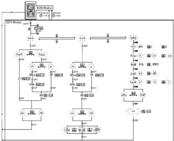
The following settings can be made in EDIT mode:
- Switching mode for OutA (air consumption [ConS] or flow rate [FLW])
-Switching function (threshold value or window comparator for OutA and OutB)
-Switching points [SP] for OutA and OutB - Air consumption switching impulse [CI] only for OutA in switching mode [ConS]
-Hysteresis [Hy] for OutA and OutB - Switching element function [no/nc] for OutA and OutB
-Colour change of the display from blue to red for flow mode (for OutB)
In addition, the following settings can be made in the special menu: - Switching of the standard conditions via [Option] (OFF, 1, 2)
-Physical units for flow rate [FLW] (l/h, scfm, l/min)
-Analogue filter [AnA.F]
-Digital filter [dIG.F]
-Physical units for air consumption [ConS] (m3, scf, l) - Switching output [nPn/PnP]
-Security code [Lock]
flowchart
graph TD
    A["RUN-Modus"] --> B["EDIT-Cancel"]
    B --> C["EDIT"]
    C --> D["EDIT-Mus"]
    D --> E["OUT-A"]
    E --> F["EDIT"]
    F --> G["FL-Lu"]
    G --> H["EDIT"]
    H --> I["SPLo"]
    I --> J["EDIT"]
    J --> K["SP"]
    K --> L["EDIT"]
    L --> M["SPLb"]
    M --> N["EDIT"]
    N --> O["H5"]
    O --> P["EDIT"]
    P --> Q["PC"]
    Q --> R["NO"]
    R --> S["EDIT"]
    S --> T["RL"]
    T --> U["EDIT"]
    U --> V["FL-Lu"]
    V --> W["EDIT"]
    W --> X["FL-Lu"]
    X --> Y["EDIT"]
    Y --> Z["FL-Lu"]
    Z --> AA["EDIT"]
    AA --> AB["FL-Lu"]
    AB --> AC["EDIT"]
    AC --> AD["FL-Lu"]
    AD --> AE["EDIT"]
    AE --> AF["FL-Lu"]
    AF --> AG["EDIT"]
    AG --> AH["FL-Lu"]
    AH --> AI["EDIT"]
    AI --> AJ["FL-Lu"]
    AJ --> AK["EDIT"]
    AK --> AL["FL-Lu"]
    AL --> AM["EDIT"]
    AM --> AN["FL-Lu"]
    AN --> AO["EDIT"]
    AO --> AP["FL-Lu"]
    AP --> AQ["EDIT"]
    AQ --> AR["FL-Lu"]
    AR --> AS["EDIT"]
    AS --> AT["FL-Lu"]
    AT --> AU["EDIT"]
    AU --> AV["FL-Lu"]
    AV --> AW["EDIT"]
    AW --> AX["FL-Lu"]
    AX --> AY["EDIT"]
    AY --> AZ["FL-Lu"]
    AZ --> BA["EDIT"]
    BA --> BB["FL-Lu"]
    BB --> BC["EDIT"]
    BC --> BD["FL-Lu"]
    BD --> BE["EDIT"]
    BE --> BF["FL-Lu"]
    BF --> BG["EDIT"]
    BG --> BH["FL-Lu"]
    BH --> BI["EDIT"]
    BI --> BJ["FL-Lu"]
    BJ --> BK["EDIT"]
    BK --> BL["FL-Lu"]
    BL --> BM["EDIT"]
    BM --> BN["FL-Lu"]
    BN --> BO["EDIT"]
    BO --> BP["FL-Lu"]
    BP --> BQ["EDIT"]
    BQ --> BR["FL-Lu"]
    BR --> BS["EDIT"]
    BS --> BT["FL-Lu"]
    BT --> BU["EDIT"]
    BU --> BV["FL-Lu"]
    BV --> BW["EDIT"]
    BW --> BX["FL-Lu"]
    BX --> BY["EDIT"]
    BY --> BZ["FL-Lu"]
    BZ --> CA["EDIT"]
    CA --> CB["FL-Lu"]
    CB --> CC["EDIT"]
    CC --> CD["FL-Lu"]
    CD --> CE["EDIT"]
    CE --> CF["FL-Lu"]
    CF --> CG["EDIT"]
    CG --> CH["FL-Lu"]
    CH --> CI["EDIT"]
    CI --> CJ["FL-Lu"]
    CJ --> CK["EDIT"]
Fig. 5: EDIT mode menu structure
7.7.1 Starting EDIT Mode
WARNING
Manipulation of signal statuses may cause serious personal injury, depending on the functioning of the machine/system.
- Note that if the switching status of the outputs is modified in EDIT mode, the new status will be effective immediately.
The following settings can be selected with the control buttons (A/B pushbutton):
- Switching output for which the characteristics is to be set
- Special menu
- Press the Edit button.
EDIT mode is active and [OutA] flashes. Lock flashes with active security blocking.
-
Press the A/B pushbuttons until the chosen security code is set.
-
Press the Edit button.
EDIT mode is active and [OutA] flashes.
7.7.2 Setting the switching characteristics of the switching outputs
Both switching outputs (OutA/OutB) can be set for flow measurement. Switching output OutA can alternatively be set for the cumulated air consumption measurement. The cumulative air consumption measurement (OutA) and flow rate measurement (OutB) can be combined.
7.7.2.1 Setting the switching function for flow measurement
i
The process for setting the switching outputs is fundamentally the same. Additionally, the switching mode [FLW] must be selected for Out A since Out A can also be configured for air consumption measurement. The colour change for the display can also be set for OutB. In the following, the process is described using the switching output OutA.
Requirement
-SFAB is in EDIT mode and [OutA] flashes
-
Press the Edit button to confirm the selection. [FLW] or [ConS] flashes.
-
Select flow rate measurement (FLW) with the A-/B pushbuttons.
-
Press the Edit button to confirm the selection.
The currently set switching function flashes.
-
Select the desired switching function with the A/B pushbuttons.
-
Press the Edit button to confirm the selection.
[SP] or [SP.Lo] flashes.
-
Set the switching point (SP or SP.Lo) with the A/B buttons.
-
Press the Edit button to confirm the set value.
With switching function window comparator: [SP.Hi] flashes. For switching function threshold value comparator: continue with step 10.
-
Set the value (SP.Hi) with the A/B pushbuttons.
-
Press the Edit button to confirm the set value.
Hy] flashes.
-
Set the value for the hysteresis (Hy) with the A/B pushbuttons.
-
Press the Edit button to confirm the set value.
[N/O] or [N/C] flashes.
-
Select the switching element function N/O/N/C with the A/B pushbuttons.
-
Press the Edit button to confirm the set value.
SFAB is in RUN mode.
- Check whether the SFAB switches as desired with a test run (vary the flow rate).
7.7.2.2 Setting the switching function for air consumption measurement Requirement
-SFAB is in EDIT mode and [OutA] flashes
- Press the Edit button to confirm the selection.
[FLW] or [ConS] flashes.
-
Select flow measurement [ConS] with the A/B buttons.
-
Press the Edit button to confirm the selection.
[CI] flashes.
-
Set the value for the air consumption switching impulse [CI] with the A/B buttons.
-
Press the Edit button to confirm the set value.
[N/O] or [N/C] flashes.
-
Select the switching element function N/O/N/C with the A/B pushbuttons.
-
Press the Edit button to confirm the set value.
SFAB is in RUN mode.
- Check whether the SFAB switches as desired with a test run (flow rate).
7.7.3 Setting the colour change (only for OutB)
In order to detect the system status over longer distances, a colour change can be set at the OutB output. If the set switching threshold is exceeded or not reached, the colour of the display changes.
The following settings can be selected:
- r.ON
-Display is red when the switching output is High (1).
- Display is blue if the switching output is Low (0).
-r.OFF
- Display is red when the switching output is Low (0).
-Display is blue if the switching output is High (1).
-bLUE
-Display is blue; the colour change function is switched off.
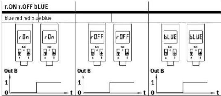
Tab. 8: Colour change
Requirement
-SFAB is in EDIT mode and [OutA] flashes
- Press B button.
[OutB] flashes.
-
Press the Edit button to confirm the selection.
-
Press the Edit button repeatedly until [rON], [rOFF] or [bLUE] flashes in the display.
-
Select the desired setting (rON, rOFF or bLUE) using the A/B pushbuttons.
-
Press the Edit button to confirm the selection.
SFAB is in RUN mode.
7.7.4 Setting the special menu
The following settings can be undertaken in the special menu:
-Standard conditions
- Physical units for flow rate (l/h, scfm or l/min)
-Analogue filter [AnA.F] with filter time constant in ms
-Digital filter [dIG.F] with smoothing in 7 levels for display and switching output
- Physical units for air consumption (m3, scf or l)
-Select the switching output [PnP] or [nPn]
- Remove security blocking [Lock] with security code
Requirement
-SFAB is in EDIT mode and [OutA] flashes
- Press the A or B pushbutton repeatedly until the menu (SPEC) is selected.
[SPEC] flashes.
- Press the Edit button to confirm the selection.
[Option] flashes. The standard conditions (OFF, 1 or 2) can be set.
7.7.4.1 Setting standard conditions
The air mass flow measured and output by the SFAB refers to standard conditions. The SFAB is factory calibrated to the physical standard conditions according to DIN 1343.
i
Changing the reference standard only adjusts the display on the sensor. The analogue value at the analogue output still refers to DIN 1343 and must be converted.
- Multiply the end value of the flow measurement range by the specified correction factor.
- End value of the analogue output refers to the end value of the measuring range. This changes the transfer function.
| REF/Cond Off 1 2 | ||||
| Standard DIN 1343 ISO 2533 | ISO 6358 | |||
| Air pressure (absolute) | [kPa] | 101.325 | 101.325 | 100 |
| Temperature | [°C] | 0 | 15 20 | |
| Humidity | [%] | 0 | 0 | 65 |
| Correction factor, measurement range limit value | 1 | 1.055 | 1.087 | |
Tab. 9: Standard conditions for flow rate and volume units
1. Select the desired setting (OFF, 1 or 2) using the A-/B pushbuttons.
2. Press the Edit button to confirm the selection.
[FLW] is displayed and the set value flashes. The unit for the flow rate (l/h, scfm or l/min) can be set.
7.7.4.2 Setting the physical unit for the flow rate
i
For the types SFAB-600U and SFAB-1000U, the unit l/h cannot be set due to display reasons.
-
Select the desired setting (l/h, scfm or l/min) using the A-/B pushbuttons.
-
Press the Edit button to confirm the selection.
[AnA.F] and the set value are displayed. The analogue filter can be set.
i
The selected physical unit is shown in RUN mode in the display at the bottom right.
7.7.4.3 Setting filter time constant for the analogue filter
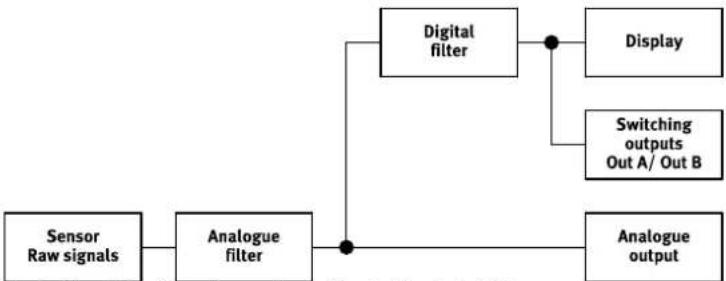
The rise time (filter time constant) of the analogue output can be changed (default value = 60 ms) with the analogue filter.
-
Select the value for the filter time constant (15 ms, 30 ms, 60 ms, 125 ms, 250 ms, 500 ms or 999 ms) with the A/B pushbuttons.
-
Press the Edit button to confirm the set value.
[dIG.F] and the set value flash. The digital filter can be set.
7.7.4.4 Setting smoothing for the digital filter
The display values can be smoothed with the digital filter. The degree of smoothing can be set in 6 steps from d1 = low smoothing to d6 = maximum smoothing. The switch-on/switch-off time of the switching outputs rises as the smoothness is increased. With d.Off the smoothing is deactivated.
flowchart
graph LR
    A["Sensor Raw signals"] --> B["Analogue filter"]
    B --> C["Digital filter"]
    C --> D["Display"]
    C --> E["Switching outputs Out A/ Out B"]
    B --> F["Analogue output"]
Fig. 6: Signal flow from the analogue filter to the digital filter
i
A high filter time constant and high smoothing can result in a switching time of several seconds.
-
Select the value for cushioning (d1 to d6 or d.OFF) with the A/B pushbuttons.
-
Press the Edit button to confirm the set value.
[ConS] is displayed and the currently selected value flashes. The unit for the air consumption (m3, scf or l) can be set.
7.7.4.5 Setting the physical unit for the air consumption
-
Select the desired setting (m3, scf or l) with the A/B pushbuttons.
-
Press the Edit button to confirm the set value.
The currently set value [PnP] or [nPn] for the switching element output flashes. The switching element output can be set.
7.7.4.6 Setting switching element output
The two switching outputs can be set as positive switches (PNP) or as zero switches (NPN) with the integrated push-pull step.
-
Select the desired setting (PNP or NPN) with the A/B pushbuttons.
-
Press the Edit button to confirm the selection.
[Lock] flashes. The security code can be set.
7.7.4.7 Setting the security code
A numerical code of up to 4 digits can be set to protect the setting from unauthorised access. The security code must be entered every time the settings are changed (EDIT mode and TEACH mode).
-
Set the desired security code with the A/B buttons.
-
Press the Edit button to confirm the selection.
The SFAB is in RUN mode.
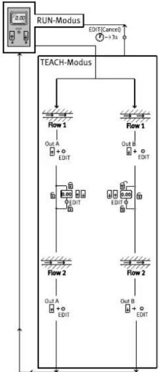
7.8 TEACH mode
The switching points can be set in the TEACH mode.
flowchart
graph TD
    A["0.00 RUN-Modus"] --> B["TEACH-Modus"]
    B --> C["Flow 1"]
    B --> D["Flow 1"]
    C --> E["Out A + EDIT"]
    D --> F["Out B + EDIT"]
    E --> G["2.00 EDIT"]
    F --> H["2.00 EDIT"]
    G --> I["Flow 2"]
    H --> J["Flow 2"]
    I --> K["Out A + EDIT"]
    J --> L["Out B + EDIT"]
    K --> M["OUT A + EDIT"]
    L --> N["OUT B + EDIT"]
    M --> O["-3s"]
    N --> P["-3s"]
    O --> Q["-3s"]
    P --> R["-3s"]
Fig. 7: TEACH mode menu structure
- Before teaching in EDIT mode, select the desired switching function (threshold value or window comparator).
Threshold value comparator Window comparator
| The (taught) switching point is derived from the average of the two measured values:-SP = 1/2(Flow 1 + Flow 2)-Special case: SP = Flow 1 = Flow 2 | The taught switching window is derived from the measured values:-SP.Lo = Flow 1-SP.Hi = Flow 2 |
Tab. 10: Switching functions
7.8.1 Teaching switching variables
i
The process for teaching the switching outputs for OutA (A button) and OutB (B button) is the same. In the following, the process is described using the switching output OutA.
- Generate flow rate (Flow 1).
- Press the A button and the EDIT button simultaneously.
The measured value is accepted as the first teach point. [OutA] and the bar graph flash.
Lock flashes with active security blocking. Set the security code with the A or B button. To accept the measured value, press the Edit button.
-
Generate flow rate (Flow 2).
-
Press the A button and the EDIT button simultaneously.
The measured value is accepted as the second teach point. The switching point (SP) or switching points (SP.Lo and SP.Hi) become valid. The SFAB is in RUN mode.
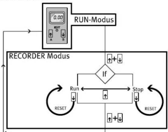
7.9 RECORDER mode
A manual accumulated air consumption measurement can be performed in RECORDER mode.
flowchart
graph TD
    A["0.00"] --> B["RUN-Modus"]
    B --> C{If}
    C -->|Yes| D["Run"]
    C -->|No| E["Stop"]
    D --> F["RESET"]
    E --> G["RESET"]
    F --> H["REORDER Modus"]
    G --> H
    H --> I["+"]
    I --> J["+"]
    J --> K["+"]
    K --> L["+"]
    L --> M["+"]
    M --> N["+"]
    N --> O["+"]
    O --> P["+"]
    P --> Q["+"]
    Q --> R["+"]
    R --> S["+"]
    S --> T["+"]
    T --> U["+"]
    U --> V["+"]
    V --> W["+"]
    W --> X["+"]
    X --> Y["+"]
    Y --> Z["+"]
    Z --> A
Fig. 8: RECORDER mode menu structure
- Press the A and B buttons simultaneously.
The SFAB is in RECORDER mode. The status of the air consumption measurement [Run] or [Stop] is displayed.
- When [Stop] is displayed, press the A button.
[Run] and a running light are displayed. The air consumption measurement has started.
- Press the A button.
Stop] is displayed. The air consumption measurement is stopped. - Press the A and B buttons.
The SFAB is in RUN mode.
i
If the RECORDER mode is left during the consumption measurement, the consumption measurement is continued in the background.
7.9.1 Resetting measured values to zero
• To reset a measure value to zero, press the B button in RECORDER mode.
8 Operation and use
i
Changes to the device settings take effect immediately at the outputs.
The air mass flow displayed by the SFAB refers to the standard condition set in the special menu under Options.
When comparing volumetric flow rates:
-Make sure that the volumetric flow rates to be compared (e.g. operating volumetric flow rate, amount supplied by a compressor, measured values of a flow sensor from another manufacturer) refer to the same standard conditions.
- After the supply voltage is switched on, the SFAB needs a warm-up time of 5 minutes before it reaches the specified accuracy.
8.1 Resetting SFAB to factory settings
i
By resetting to the factory settings, the current settings are lost. Note down current settings before resetting.
- Switch off operating voltage.
- Press and hold the A button, B button and Edit button.
- Switch on operating voltage.
The SFAB is in RUN mode.
9 Service
- Turn off energy source and compressed air.
- Clean sensor with non-abrasive cleaning agents.
10 Fault clearance
| Fault description Cause | Remedy | |
| Incorrect measured value indicator | SFAB operated with non-permitted medium | Operate SFAB only with permitted media. |
| SFAB contaminated Replace device. | ||
| In case of flow rate measurement: measured value is shown flashing | Measurement outside permitted measuring range | Maintain permitted measuring range ➔ 12 Technical data. Accuracy refers only to the permitted measuring range. |
| incorrect flow direction Correct the tubing ➔ 6.1 Pneumatic installation. | ||
| In case of air consumption measurement: measured value is shown flashing | Measuring range end value has been exceeded at least once. Specified accuracy can therefore probably not be maintained. | Make sure that the end value of the measuring range is not exceeded. |
| Outputs do not switch corresponding to the setting | Short circuit or overload at corresponding output | Correct short circuit or overload. |
| Settings cannot be edited (Lock) | Access protection active Enter the security code. | |
| O.FLO | Measurement range exceeded (displayed in RUN mode) | Check operating conditions. |
| Er1, Er3, Er4 | Device faulty | Replace device. |
| Er2 | Moisture or dirt in the compressed air | Replace device. |
| Er9 | Measurement range under-shot (displayed in SHOW mode) | Check operating conditions. |
| Er10 | Measurement range exceeded (displayed in SHOW mode) | Check operating conditions. |
| Er17 | Undervoltage | Maintain operating voltage. Check electrical wiring |
Tab. 11
11 Disassembly
- Turn off energy source and compressed air.
-
Separate connections from the sensor.
-
For panel mounting: loosen retaining screws.
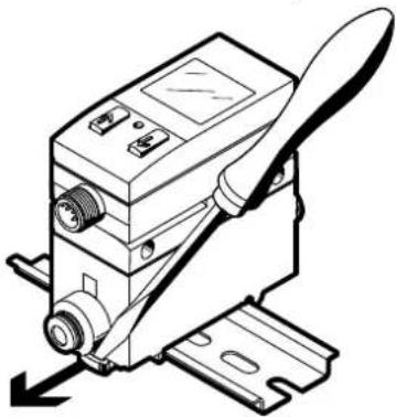
For H-rail or wall mounting: loosen the fixing slide → Fig. 9
natural_image
Technical line drawing of a mechanical device with a lever and base mount (no text or symbols)Fig. 9: Disassembly
12 Technical data
| SFAB -10U -50U -200U -600U -1000U | ||||||
| General | ||||||
| Certification RCM Mark, c UL us - Recognized (OL) | ||||||
| CE marking Declaration of Conformity | →www.festo.com/sp | |||||
| Measured variable Flow rate, consumption | ||||||
| Flow direction unidirectional P1 → P2 | ||||||
| Measurement principle thermal | ||||||
| Flow measuring range [l/min] 0.1 ... 10 0.5 | ... 50 2 ... 20 | 00 6 ... 600 | 10 ... | 1000 | ||
| Operating pressure [bar] | 0 ... 10 | |||||
| Operating pressure [kPa] | 0 ... 1000 | |||||
| Nominal pressure [kPa] | 600 | |||||
| Pressure drop [kPa] | < 10 | |||||
| Ambient temperature [°C] | 0 ... 50 | |||||
| Temperature of medium [°C] | 0 ... 50 | |||||
| Nominal temperature [°C] | 23 | |||||
| Operating medium Compressed air in | accordance with ISO 8573-1:2010 [6:4:4] | Compressed air in accordance with ISO 8573-1:2010 [7:4:4] | ||||
| Nitrogen | ||||||
| Output, general(1)(2) | ||||||
| Accuracy of zero point(1) [% FS] | ±0.3 | |||||
| Accuracy of margin(3) [% FS] | ±3 | |||||
| Repetition accuracy of zero point [% FS] | ±0.2 | |||||
| Repetition accuracy of spread [% FS] | ±0.8 | |||||
| Temperature coefficient of spread [% FS/K] | ≤ 0.1 | |||||
| Pressure-dependent [% FS/ spread 100 kPa] | ±0.5 | |||||
| Switching output | ||||||
| Switching output | 2x PNP or 2x NPN, adjustable | |||||
| Switching function Window comparator or threshold value comparator,adjustable | ||||||
| Switching element function | N/C or N/O contact, adjustable | |||||
| Max. output current [mA] | 100 | |||||
| Voltage drop [V] | max. 1.5 | |||||
| Switch-on time | adjustable (factory setting: approx. 80 ms) | |||||
| Switch-off time | adjustable (factory setting: approx. 80 ms) | |||||
| Inductive protective circuit | adapted to MZ, MY, ME coils | |||||
| Analogue output | ||||||
| Characteristic flow rate curve [l/min] 0 ... 10 0 ... 50 0 ... 200 0 ... 600 0 ... 1000 | ||||||
| Output characteristic curve for current [mA] | 4 ... 20 | |||||
| Max. load resistance of current output [Ω] | 500 | |||||
| Min. load resistance at voltage output [kΩ] | 10 | |||||
| Rise time [ms] | adjustable:15, 30, 60 (factory setting), 125, 250, 500, 999 | |||||
| Output, additional data | ||||||
| Short circuit current rating | yes | |||||
| Overload protection | present | |||||
| Electronics | ||||||
| Operating voltage range [V DC] | 15 ... 30 | |||||
| Reverse polarity protection | for all electrical connections | |||||
| SFAB -10U -50U -200U -600U -1000U | |||||
| Electromechanics | |||||
| Electrical connection | Straight plug, M12x1, 5-pin | ||||
| Max. connecting cable length [m] | < 10 | ||||
| Mechanics | |||||
| Mounting position | any | ||||
| Product weight [g] | 160 | ||||
| Note on materials, housing | Reinforced polyamide, polycarbonate | ||||
| Display/operation | |||||
| Display type | Illuminated LCD, blue | ||||
| Displayable units | l/min, scf, scfm, l, m^3 , scf, l/h | l/min, scf, scfm, l, m^3 | |||
| Setting range for flow rate threshold value | 1% FS ... 100% FS | ||||
| Setting range for consumption impulse threshold value [l] | 0.1 ... 1999.9 | 0.2 ... 1999.9 | 1 ... 1999.9 | 2 ... 1999.9 | |
| [m3] | 0.01 ... 199.99 | 0.1 ... 1999.9 | 1 ... 19999 | ||
| [scf] | 0.01 ... 199.99 | 0.03 ... 199.99 | 0.1 ... 999.9 | ||
| Hysteresis setting range | 0% FS ... 90% FS | ||||
| Immissions/emissions | |||||
| Storage temperature [°C] | -20 ... +80 | ||||
| Degree of protection | IP65 | ||||
| Protection class | III | ||||
1) Accuracy under nominal conditions (6 bar, 23 °C and horizontal mounting position)
2) % FS = % of the flow rate range end value (full scale)
3) The accuracy of the zero point and accuracy of the spread together correspond to the accuracy of the flow rate: accuracy of the flow rate = ± (0.3% FS + 3% o.m.v.). % o.m.v. = % of measured value
Tab. 12: Technical data
12.1 Examples for calculating the maximum error of the display
- Flow rate measuring range: 10 ... 1000 l/min (FS = 1000)
- Measured value: 600 l/min
Spread error (e.g. ±3% FS)
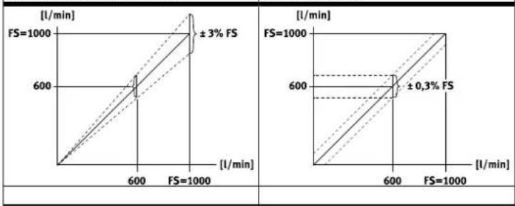
Tab. 13
Spread error and zero point error
The spread error is proportional to the measured value. At 600 l/min, the spread error is 3% of the measured value = 18 l/min.
The zero point error is independent of the measured value. It is 0.3% FS = 3 l/min.
Display error under nominal conditions (6 bar, 23 °C):
The display error under nominal conditions is the result of adding the spread and zero point errors. The actual flow rate is in the range of 600 ± (18 + 3) l/min = 600 ± 21 l/min.
Display error under different nominal conditions (e.g. 8 bar, 40 °C):
Temperature and pressure errors are spread errors. The temperature error at 40 °C is ±0.1% FS/K x 17 K = ±1.7% of the measured value = ±10.2 l/min.
The pressure error at 8 bar is
±0.5% FS/bar x 2 bar = ±1% of the measured value = ±6 l/min.
The error of the display at deviating nominal conditions results from the addition of all error values (span, zero point, temperature, pressure). The actual flow rate is therefore in the range of 600 ± (18 + 3 + 10.2 + 6) l / min = 600 ± 37.2 l / min .
- FESTO
- About this document
- Applicable Documents
- Safety
- General safety instructions
- Intended use
- Training of qualified personnel
- Range of application and approvals
- Additional information
- Product design
- Functional principle
- Assembly
- H-rail (manifold assembly)
- Wall mounting
- Plate mounting
- Rotate display
- Installation
- Pneumatic installation
- Electrical installation
- WARNING
- Risk of injury due to electric shock.
- Circuit diagrams
- Commissioning
- Switching outputs
- Switching functions
- Threshold value comparator in the flow rate measurement for OutA or OutB
- Window comparator in the flow rate measurement for OutA or OutB
- Consumption switching pulses [CI] for cumulative air consumption measurement for OutB
- Preparing commissioning
- RUN mode
- SHOW mode
- EDIT mode
- Starting EDIT Mode
- Setting the switching characteristics of the switching outputs
- Setting the switching function for flow measurement
- Requirement
- Setting the switching function for air consumption measurement Requirement
- Setting the colour change (only for OutB)
- Setting the special menu
- Setting standard conditions
- Setting the physical unit for the flow rate
- Setting filter time constant for the analogue filter
- Setting smoothing for the digital filter
- Setting the physical unit for the air consumption
- Setting switching element output
- Setting the security code
- TEACH mode
- Teaching switching variables
- RECORDER mode
- Resetting measured values to zero
- Operation and use
- Resetting SFAB to factory settings
- Service
- Disassembly
- Examples for calculating the maximum error of the display
- Spread error and zero point error
- Display error under nominal conditions (6 bar, 23 °C):
- Display error under different nominal conditions (e.g. 8 bar, 40 °C):
Brand : Festo
Model : SFAB-1000U-WQ10-2SV-M12
Category : Measurement