SFAW-32T-X-E-PNLK-PNVBA-M12 - Measurement Festo - Free user manual and instructions
Find the device manual for free SFAW-32T-X-E-PNLK-PNVBA-M12 Festo in PDF.


| Product Type | Measurement device (sensor/transducer) |
| Model | SFAW-32T-X-E-PNLK-PNVBA-M12 |
| Brand | Festo |
| Dimensions (L x W x H) | Approx. 80 mm x 50 mm x 30 mm |
| Weight | Approx. 0.2 kg |
| Power Supply | 10-30 V DC |
| Output Signal | PNP/NPN, analog voltage or current (depending on variant) |
| Measurement Principle | Inductive or capacitive sensing (based on application) |
| Measuring Range | Up to 32 mm (model-dependent) |
| Accuracy | ±0.5% of full scale |
| Environmental Protection | IP67 (dust-tight and waterproof) |
| Operating Temperature | -25°C to +70°C |
| Connection | M12 connector |
| Maintenance | Clean with dry cloth; no recalibration needed |
| Safety | Reverse polarity protection; short-circuit protected |
| Spare Parts | Available through Festo distributors |
| Repairability | Non-repairable; replace unit if defective |
| General Information | CE marked; RoHS compliant |
Frequently Asked Questions - SFAW-32T-X-E-PNLK-PNVBA-M12 Festo
User questions about SFAW-32T-X-E-PNLK-PNVBA-M12 Festo
0 question about this device. Answer the ones you know or ask your own.
Ask a new question about this device
Download the instructions for your Measurement in PDF format for free! Find your manual SFAW-32T-X-E-PNLK-PNVBA-M12 - Festo and take your electronic device back in hand. On this page are published all the documents necessary for the use of your device. SFAW-32T-X-E-PNLK-PNVBA-M12 by Festo.
USER MANUAL SFAW-32T-X-E-PNLK-PNVBA-M12 Festo
natural_image
Technical line drawing of a mechanical component with hexagonal nuts and a rectangular housing (no text or symbols)FESTO
Operating instruction
Translation of the original instructions
IO-Link is a registered trademark of its respective trademark holder in certain countries.
Table of contents
1 Applicable documents.... 5
2 Safety....5
2.1 Safety instructions....5
2.2 Intended use.... 5
2.3 Training of qualified personnel....5
2.4 UL/CSA certification.... 5
3 Additional information....6
4 Product overview.... 6
4.1 Structure....6
4.1.1 Product design....6
4.1.2 Display components....7
4.2 Function.... 10
4.2.1 Operating statuses.... 10
4.2.2 Switching outputs.... 10
4.2.3 Analogue output.... 11
4.2.4 Filter.... 12
4.2.5 Functional principle.... 12
4.2.6 Security code....13
4.2.7 Minimum value and maximum value....13
5 Mounting.... 14
5.1 Inlet situation and outlet situation.... 14
5.1.1 Mounting position/inflow.... 15
5.2 Mounting.... 16
5.2.1 Installing sensor without mounting accessories.... 16
5.2.2 Mounting sensor with wall mounting.... 16
5.3 Tubing sensor....17
5.4 Changing fluid connector.... 17
6 Installation.... 18
6.1 Installation, electrical.... 18
7 Commissioning....19
7.1 Switching on the sensor in RUN mode.... 19
7.2 Displaying parameters in SHOW mode.... 19
7.2.1 Starting SHOW mode.... 20
7.2.2 Show and reset minimum value/maximum value.... 21
7.2.3 Display mean value and reverse related filter time constants.... 21
7.3 Configuring the sensor in EDIT mode.... 21
7.3.1 Entering the security code.... 24
7.3.2 Setting the switching characteristics of the switching outputs.... 24
7.3.3 Setting display units and analogue output.... 25
7.3.4 Changing sensor settings....26
7.3.5 Replicating parameters.... 26
7.4 Teach-in switching points in TEACH mode....27
7.5 Measure volume manually in RECORDER mode.... 27
8 Operation.... 28
8.1 Reset parameters to factory setting....28
9 Cleaning.... 28
10 Fault clearance.... 28
11 Removal....29
12 Technical data....30
12.1 Technical data of UL/CSA certification.... 33
12.2 Hole patterns and dimensional drawings.... 34
12.2.1 Hole pattern for direct mounting.... 34
12.2.2 Hole pattern for wall mounting.... 34
12.2.3 Dimensional drawing of customer-specific fluid connections 35
1 Applicable documents

All available documents for the product → www.festo.com/sp.
2 Safety
2.1 Safety instructions
- Only use the product in its original condition without unauthorised modifications.
-Only use the product if it is in perfect technical condition. - Do not use the product in combination with flammable, caustic, vapour-emitting or other media hazardous to health.
- Take into account the ambient conditions at the location of use.
- Only use media in accordance with the specifications Technical data.
- Foreign matter and other contaminants in the operating medium may damage the product and cause incorrect measurements and malfunctions.
- Check the operating medium to determine the media compatibility with the materials it contacts.
- Observe the identifications on the product.
- Remove all transport packaging.
2.2 Intended use
The flow sensor monitors the flow rate, volume and temperature of liquid media in piping systems or terminal devices in industry.
2.3 Training of qualified personnel
Work on the product may only be carried out by qualified personnel who can evaluate the work and detect dangers.
The technicians have knowledge and experience in handling fluidic systems in the intended area of application.
2.4 UL/CSA certification
In combination with the UL inspection mark on the product, the information in this section must also be observed in order to comply with the certification conditions of Underwriters Laboratories Inc. (UL) for USA and Canada.
UL/CSA approval information
| Product category code QUYX, QUYX7 | ||
| File number E322346 | ||
| Considered standards UL 610101, CAN/CSA-22.2 No. 61010-1 | ||
| UL mark |  | US LISTED |
Tab. 1: UL/CSA certification information
Only for connection to a NEC/CEC Class 2 supply.

WARNING
The unit shall be supplied by a power source which fulfils the requirements on a limited-energy circuit in accordance to IEC/EN/UL/CSA 61010-1 or on a Limited Power Source (LPS) in accordance to IEC/EN/UL/CSA 60950-1 or IEC/EN/UL/CSA 62368-1 or a Class 2 circuit in accordance to NEC or CEC.
3 Additional information
- Contact the regional Festo contact if you have technical problems → www.festo.com.
- Accessories and spare parts → www.festo.com/catalogue.
4 Product overview
4.1 Structure
4.1.1 Product design
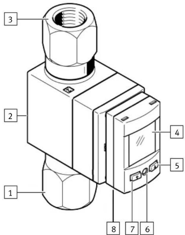
Fig. 1: Control elements and connection elements
1 Fluid port 1, input, rotatable
2 Locking plate
3 Fluid port 2, output, rotatable
4 Display, rotatable
5 Pushbutton [B]
6 [Edit] key
7 Pushbutton [A]
8 Electrical connection
4.1.2 Display components
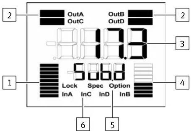
1 Bar graph for input signal InA
2 Output display
3 Main display, e. g. measured value
4 Bar graph for input signal InC or InD
5 Lower display, e.g. unit
6 Status information/input display
Fig. 2: LCD display
Symbols on the display
| Example for LCD display | Meaning |
| Output display | |
| ‘OutA’ Switching output OutA selected, flashes with active IO-Link | |
| ‘OutA’ Switching output OutA set | |
| ‘OutC’ Switching output OutC selected | |
| ‘OutC’ Switching output OutC set | |
| ‘OutB’ Switching output OutB selected | |
| ‘OutB’ Switching output OutB set | |
| ‘OutD’ Analogue output OutD selected | |
| ‘OutD’ Switching output OutD set | |
| Information/input display | |
| Input signal InA: graphic display of the current measured value related to the maximum measured value of the measuring range | |
| Input signal InC: graphic display of the volume measurement | |
| ‘InA’ Input signal InA selected | |
| ‘InC’ Input signal InC selected | |
| ‘InB’ Input signal InB selected | |
| ‘Lock’ Security code activated | |
| ‘Spec’ Special menu activated | |
Tab. 2: Symbols on the display
| Example for LCD display Meaning | ||
| Main display Lower display | ||
| Measured value indicator and unit in the RUN mode | ||
| ‘17.3’ ‘I/min’ Me | asured value indicator and unit | |
| Menu for the switching outputs | ||
| ‘Edit’ ‘Flow’ Edit | menu for the switching outputs | |
| _I- ‘Fctn’ Setting | the switching function: threshold value comparator | |
| _I-I_ ‘Fctn’ Setting | ing the switching function: window comparator | |
| ‘18.0’ ‘SP’ Value | of switching point, only for threshold value comparator | |
| ‘8.0’ | ‘SP.Lo’ | Value of lower switching point, only for window comparator |
| ‘12.2’ | ‘SP.Hi’ | Value of upper switching point, only for window comparator |
| ‘2.8’ ‘HY’ | Hysteresis value | |
| ‘N/O’ | ‘logic’ | Switching characteristics of the switching outputs: ‘NO’ = N/O contact, ‘NC’ = N/C contact |
| ‘bLUE’ | ‘COLR’ Display colour: | ‘bLUE’ = blue, colour change function deactivated ‘R.ON’ = red when switching output set ‘R.OFF’ = red when the switching output not set |
| ‘200’ ‘PULS’/‘M$EC’ Width of the volume pulse | ||
| Menu for the analogue output | ||
| ‘I/min’ | ‘Flow’/‘Unit’ | Display unit for the flow measurement |
| ‘1_5V’ | ‘Out’ | Analogue output, switchable between ‘0_10V’, ‘1_5V’, ‘4_20MA’ |
| ‘93.0’ ‘In.Hi’/‘%’ | Scaling of the analogue output: set end value of the flow rate characteristic or temperature characteristic, specified in % FS | |
| ‘3.1’ ‘In.Lo’/‘%’ | Scaling of the analogue | output: set start value of the flow rate characteristic or temperature characteristic, specified in % FS |
| ‘Ltr’ ‘VOL’/‘Unit’ | Display unit for volume | measurement |
| ‘°C’ ‘tEMP’/‘Unit’ | Display unit for temperature measurement | |
| Menu for extreme values and mean values | ||
| ‘5.1’ ‘MIN’/‘l/Min’ | Minimum measured flow rate since switch-on or the last reset | |
| ‘30.8’ ‘MAX’/‘l/Min’ | Maximum measured flow rate since switch-on or the last reset | |
| ‘20.2’ ‘MIN’/‘°C’ | Minimum measured temperature since switch-on or the last reset | |
| ‘50.5’ ‘MAX’/‘°C’ | Maximum measured temperature since switch-on or the last reset | |
| ‘20.8’ ‘AVER’/‘l/Min’ | Average of the flow measurement, filter time constant switch-able between 650 ms, 1200 ms, 2500 ms | |
| Menu for the device settings in the special menu | ||
| ‘1200’ | ‘Filt’ | Value of the filter time constant for the flow rate measurement signal |
| ‘10’ | ‘Eco’ | Economy mode: time after which the display background lighting is switched off |
| ‘PNP’ | ‘bin’/‘Out’ Switchover of the switching outputs between PNP and NPN | |
| ‘FLOW’ | ‘bin’/‘Pin4’ | Switchover of the switching signal at pin 4 between flow monitoring and volume pulse |
| ‘FLOW’ | ‘bin’/‘Pin2’ | Switchover of the switching signal or the analogue output signal at pin 2 between flow rate and temperature monitoring |
| ‘FLOW’ | ‘ANLG’/‘Pin5’ | Switchover of the analogue output signal at pin 5 between flow measurement and temperature measurement |
| ‘OFF’ | ‘Lock’/‘Code’ Activation and specification of the security code | |
| ‘OFF’ | ‘MASt’ | Activation of the IO-Link master function for replication of parameters |
Tab. 3: Example for LCD display
4.2 Function
4.2.1 Operating statuses
| Operating status Function | |
| RUN mode | - Basic state after the operating voltage has been applied.- Display of the current measured value.- Display of the selected inputs and outputs.- Switchover between the measured variables of flow rate, volume and temperature. |
| SHOW mode | - Display of current settings of the switching outputs and analogue output.- Display and reset of the minimum and maximum values. |
| EDIT mode | - Setting or modification of parameters. |
| TEACH mode | - Acceptance of the current measured value to specify switching points. |
| RECORDER mode | - Manual measurement of the accumulated volume. |
Tab. 4: SFAW operating statuses
4.2.2 Switching outputs
4.2.2.1 Switching functions
Threshold value comparator in the flow measurement for OutA or OutD and in the temperature measurement for OutB
| Function Normally open contact (N/O) Normally closed (N/C contact) | ||
| Switching function:- 1 switching point (SP)TEACH mode1):- 2 teach points (TP1, TP2)- SP = 1/2 (TP1 + TP2) | 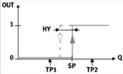 | 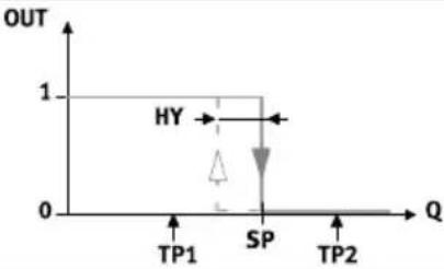 |
1) Only with flow measurement
Tab. 5: Threshold value comparator: setting of switching point SP and hysteresis HY
Window comparator in the flow measurement for OutA or OutD and in the temperature measurement for OutB
Function Normally open contact (N/O) Normally closed (N/C contact)
Switching function:
- 2 switching points (SP.Lo, SP.Hi)
- 2 teach points (TP1, TP2)
- TP1 = SP.Lo, TP2 = SP.Hi
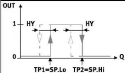
line
| Q | OUT | | -------- | --- | | TP1=SP.Lo | 0 | | TP2=SP.Hi | 1 |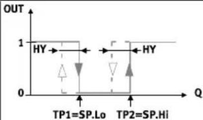
line
| Q | OUT | | -------- | --- | | TP1=SP.Lo| 0 | | TP2=SP.Hi| 1 |1) Only with flow measurement
2) SP.Lo = smaller value, SP.Hi = larger value, independent of the Teach sequence
Tab. 6: Window comparator: setting of switching points SP.Lo and SP.Hi and hysteresis HY
4.2.2.2 Colour change
A red colour change can be set in the display for OutA, OutB and OutD dependent on the switching status. The colour changes enable the system status to be identified from a distance.
The display always shows the measured variable that first caused the colour change. The unit and the associated OutA, OutC or OutD output flash in the lower display. The display remains red until all switching outputs are in the 'blue' status again.
4.2.2.3 Volume pulse
A threshold value for the volume is set in the cumulative volume measurement. If the configured threshold value is reached, a switching impulse is emitted at the OutC output for a configurable period. The volume measurement is restarted at every switching pulse.
Setting of N/O contact (NO) Setting N/C contact (NC)
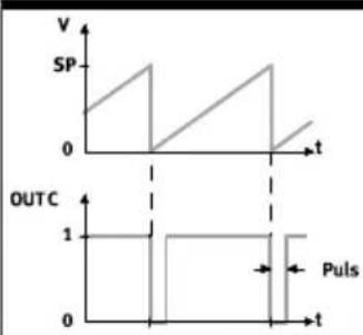
line
| Time | SP | OUTC | |------|-----|------| | t | 0 | 1 | | t=0 | 1 | 0 | | t=1 | 0 | 1 | | t=2 | 1 | 0 | | t=3 | 0 | 1 |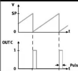
line
| t | SP | OUTC | |-------|-----|------| | 0 | 0 | 0 | | 1 | 1 | 1 | | 2 | 0 | 0 | | 3 | 1 | 1 | | 4 | 0 | 0 |Tab. 7: Volume pulse with accumulated volume measurement
4.2.3 Analogue output
Analogue signal
The signal of the analogue output can be assigned the physical measured variables of flow rate or temperature. The physical measured value of flow rate is configured as standard.
Output signal
The analogue output can be configured either as voltage output 0 ... 10 V oder 1 ... 5 V or as current output 4 ... 20 mA. By default the voltage output is set to 0 ... 10 V.
Scaling of the analogue signal
The default setting for the analogue output signal is 0 ... 10 V, 1 ... 5 V or 4 ... 20 mA for the complete sensing range "Full Scale (FS)". If only part of the sensing range is to be used, the analogue value output can be scaled to the partial range.
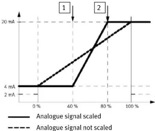
line
| Percentage | Analogue signal scaled (mA) | Analogue signal not scaled (mA) | | ---------- | ---------------------------- | -------------------------------- | | 0% | 4 | 2 | | 40% | 4 | 4 | | 80% | 20 | 10 | | 100% | 20 | 20 |1 Starting point of the scaled sensing range (In.Lo)
2 End point of the scaled sensing range (In.Hi)
Fig. 3: Example: scaling of the analogue signal at the current output
4.2.4 Filter
The filter smoothes the flow rate measurement signal. Smoothing takes place in 8 steps and affects all outputs. The switching times of the flow-related switching outputs and the rise time and fall time of the analogue output change.
4.2.5 Functional principle
The flow velocity is recorded in accordance with the vortex principle. The flow rate and the accumulated volume are calculated from the flow velocity. An optional integrated temperature sensor records the temperature of medium.
Interfacing to higher-level systems is provided by 2 switching outputs via an analogue output or an IO-Link interface depending on the type.
The switching outputs can be configured to monitor a threshold value or a range. PNP or NPN and N/O contact (NO) or N/C contact (NC) can be set for each switching output as required. The process values can be read out and parameters changed and transmitted to additional devices through the IO-Link interface.
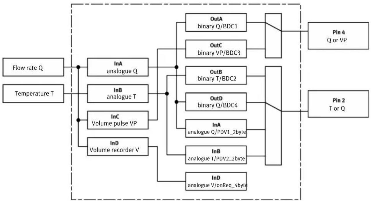
flowchart
graph TD
    A["Flow rate Q"] --> B["InA analogue Q"]
    C["Temperature T"] --> D["InB analogue T"]
    D --> E["InC Volume pulse VP"]
    D --> F["InD Volume recorder V"]
    B --> G["OutA binary Q/BDC1"]
    B --> H["OutC binary VP/BDC3"]
    D --> I["OutB binary T/BDC2"]
    D --> J["OutD binary Q/BDC4"]
    E --> K["InA analogue Q/PDV1_2byte"]
    F --> L["InB analogue T/PDV2_2byte"]
    G --> M["Pin 4 Q or VP"]
    H --> N["Pin 2 T or Q"]
    I --> O["InD analogue V/onReq_4byte"]
Fig. 4: SFAW-...PNLK-PNVBA-... signal structure
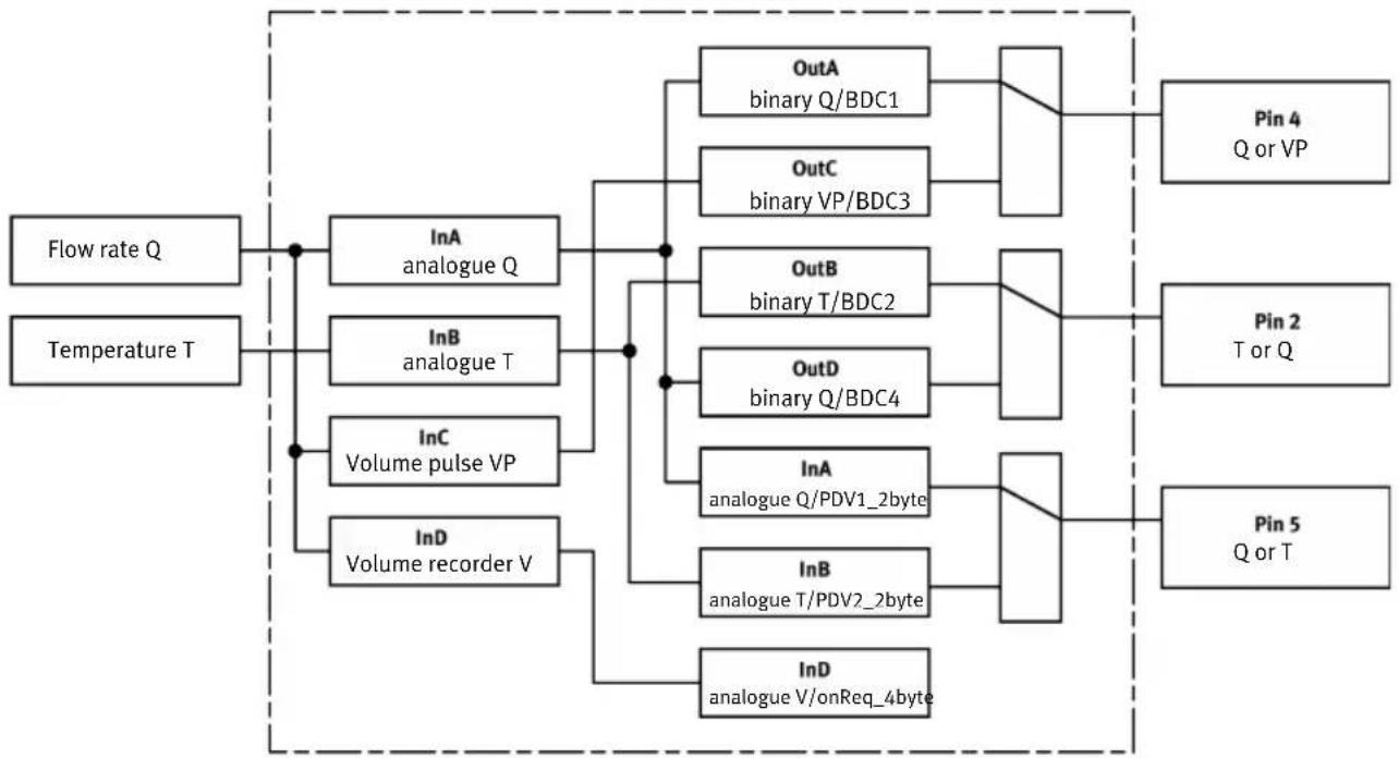
flowchart
graph TD
    A["Flow rate Q"] --> B["InA analogue Q"]
    C["Temperature T"] --> D["InB analogue T"]
    D --> E["InC Volume pulse VP"]
    D --> F["InD Volume recorder V"]
    B --> G["OutA binary Q/BDC1"]
    B --> H["OutC binary VP/BDC3"]
    D --> I["OutB binary T/BDC2"]
    D --> J["OutD binary Q/BDC4"]
    E --> K["InA analogue Q/PDV1_2byte"]
    F --> L["InB analogue T/PDV2_2byte"]
    F --> M["InD analogue V/onReq_4byte"]
    G --> N["Pin 4 Q or VP"]
    H --> O["Pin 2 T or Q"]
    I --> P["Pin 5 Q or T"]
Fig. 5: SFAW-...PNLK-PN-VBA-... signal structure
4.2.6 Security code
A 4-digit numeric code can be set to protect the device settings from unauthorised access. The security code must be entered in EDIT mode and TEACH mode when changing settings.
The IO-Link interface offers additional options for blocking access.
4.2.7 Minimum value and maximum value
The minimum values and the maximum values for the flow measurement or the temperature measurement are displayed and reset in the SHOW mode.
i
The minimum and maximum values are reset when the operating voltage is switched off.
5 Mounting
5.1 Inlet situation and outlet situation
The specified accuracies of the sensor are achieved if the inlet and outlet sections on the sensor are sufficiently long and straight. In addition, the sensor should not have any disruptive geometries such as edges, curves or tapering.
Before installation, observe the following conditions:
| SFAW- 32-... 100-... | ||
| Inside diameter D of the flow sensor 11 mm 19 mm | ||
| Min. internal diameter of laminar flow inlet 1.1 x D | 1.05 x D | |
| Laminar flow inlet type 10 cm | ||
| Min. laminar flow outlet 5 cm | ||
Tab. 8: Minimum requirements for fluid connection
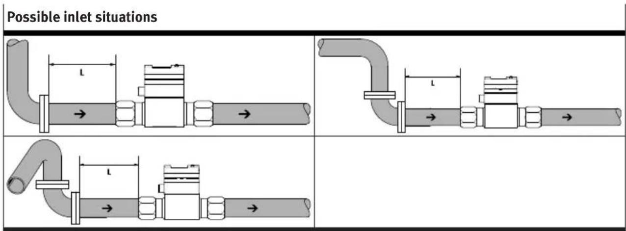
Tab. 9: Possible inlet situations
Mounting
5.1.1 Mounting position/inflow
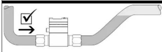
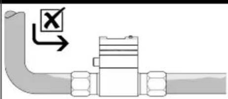
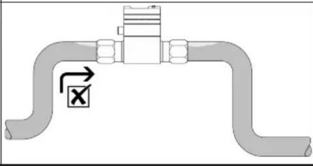
- The sensor is unidirectional and can therefore only provide meaningful measurement values in one direction of flow. Flow in the opposite direction also actuates the paddle, but with many irregular pulses. The defined relationship between the vortex frequency and the flow velocity no longer exists. Values that appear plausible are still shown on the display.
- If the flow direction is correct, the mounting position is arbitrary.
- The specified accuracies are maintained with inlet sections that are as long and straight as possible.
- The inside diameter of the inlet section must not be smaller than the inside diameter at the sensor measuring point.
- Vortices generated by external interfering bodies will influence the measurement result. External sources of interference can be throttles, valves, pipe bends and double pipe bends. These additional superimposed vortices falsify the measurement result and should therefore be avoided in the design.
In addition, air or air bubbles affect the measurement and lead to incorrect measurement results. Air in the fluidic system is often caused by incorrect installation situations. The correct mounting position must be observed and a back pressure that is not too low must be maintained.
The following table shows the correct and incorrect installation situations.
Correct installation situation Incorrect installation situation
natural_image
Pure diagram of a pipe fitting with a valve and directional arrow, no text or symbols present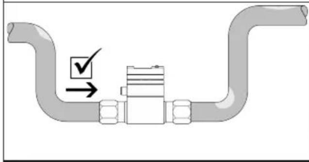
natural_image
Pure diagram of a pipe fitting with no text, numbers, or symbols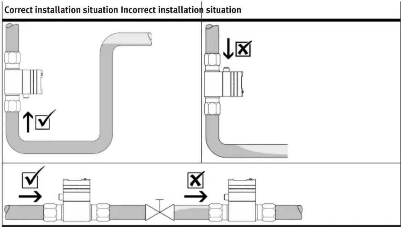
Tab. 10: Correct and incorrect installation situations
5.2 Mounting
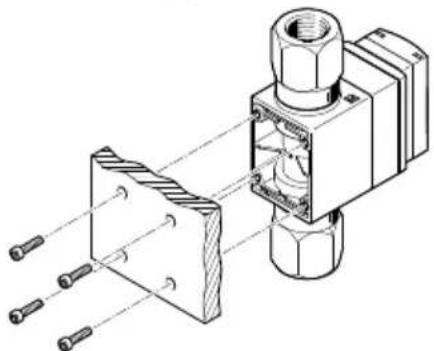
5.2.1 Installing sensor without mounting accessories
The mounting position is as desired.
natural_image
Technical illustration of a mechanical assembly with pins and housing (no text or symbols)Fig. 6: Direct mounting
i Note hole pattern → Fig. 11.
- Remove the locking plate.
- Screws: Allen key SW 2 mm
- Mount the sensor with 4 M3 screws.
-Wall hole diameter: maximum 3.3 mm
-Tightening torque: maximum 0.5 Nm
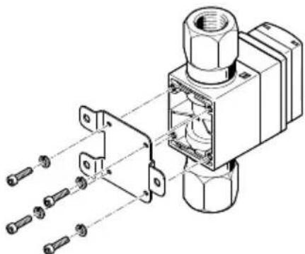
5.2.2 Mounting sensor with wall mounting
The mounting position is as desired.
Mounting
natural_image
Technical line drawing of a mechanical assembly with bolts and housing (no text or symbols)Fig. 7: Wall mounting SFAW-...-W-...
i
Note hole pattern Fig. 12.
- Remove the locking plate.
-Screws: Allen key SW 2 mm
- Install the wall mounting on the sensor with 4 M3 screws.
- Tightening torque: maximum 0.5 Nm
5.3 Tubing sensor
The medium is fed in at fluid port 1 and removed at fluid port 2→ Fig. 1.
-
Screw a supply line into the fluid port 1 of the sensor. Do not tilt the thread when screwing it in.
-
Screw in a drain line at fluid port 2 of the sensor. Do not tilt the thread when screwing it in.
i
Observe the dimensional drawing for the customer-specific fluid ports Fig. 13.
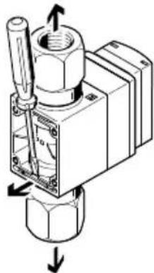
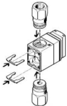
5.4 Changing fluid connector
- Remove the locking plate.
- Remove the clamps and pull out the fluid connectors.
natural_image
Technical diagram of a mechanical valve assembly with directional arrows indicating movement (no text or labels)- Insert new fluid connectors.
-Make sure the O-rings are seated correctly.
Installation
- Insert the clamps and push them fully into the housing.
natural_image
Mechanical assembly diagram showing a connector with threaded fasteners and internal components (no text or labels)- Mount the locking plate with 4 M3 screws.
- Tightening torque: maximum 0.5 Nm
6 Installation
6.1 Installation, electrical

WARNING
Risk of injury due to electric shock.
- For the electrical power supply, use only PELV circuits in accordance with IEC 60204-1/EN 60204-1 (Protective Extra-Low Voltage, PELV).
- Observe the general requirements of IEC 60204-1/EN 60204-1 for PELV circuits.
- Only use voltage sources that ensure a reliable electric separation from the mains network in accordance with IEC 60204-1/EN 60204-1.
i
The switching outputs at pin 2 and pin 4 can be wired as PNP or NPN connections.
- Pay attention to the wiring when configuring the switching outputs 7.3.4 Changing sensor settings.
- Connect the sensor.
- Maximum permissible cable length: 30 m, with IO-Link 20 m
-Plug tightening torque: maximum 0.5 Nm
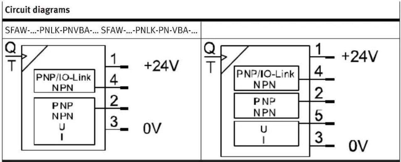
| Plug Pin Allocation | 1) | Wire colour |
| 5-pin M12 1 +24 | V DC operating voltage Brown (BN) | |
| 2 Switching output OutB or OutD or analogue output White (WH) | ||
| 3 0 V Blue (BU) | ||
| 4 Switching output OutA or OutC or IO-Link (C/Q line) Black (BK) | ||
| 5 Analogue output or not assigned Grey (GY) |
1) Observe signal structures.
Tab. 11: Pin allocation
other
| Pin | Output | | --- | --- | | PNP/IO-Link NPN | 1 | | PNP NPN U I | 2 | | PNP/IO-Link NPN | 3 | | PNP/IO-Link NPN | 4 | | PNP/IO-Link NPN | +24V | | PNP/IO-Link NPN | 0V | | PNP NPN U I | 1 | | PNP NPN U I | 2 | | PNP NPN U I | 3 | | PNP NPN U I | 4 | | PNP NPN U I | 5 | | PNP NPN U I | 0V | The diagram shows a circuit diagram with 'SFAW-' and 'PNLK-PNVBA-' connected to the top node of the circuit. The output is labeled as 'Q/T'.Tab. 12: Circuit diagrams
7 Commissioning
7.1 Switching on the sensor in RUN mode
The basic state of the sensor is the RUN mode. The current values are displayed.
The basic state can be reached from other modes:
-Press and hold the [Edit] key for 3 seconds.
- After a monitoring time has elapsed (Timeout).
- Switch on the operating voltage.
The sensor is in RUN mode.
The signals active at the outputs are displayed → 4.2.5 Functional principle.
- Press the [A] or [B] key to switch between the flow rate, volume and temperature measured variables Fig. 8.
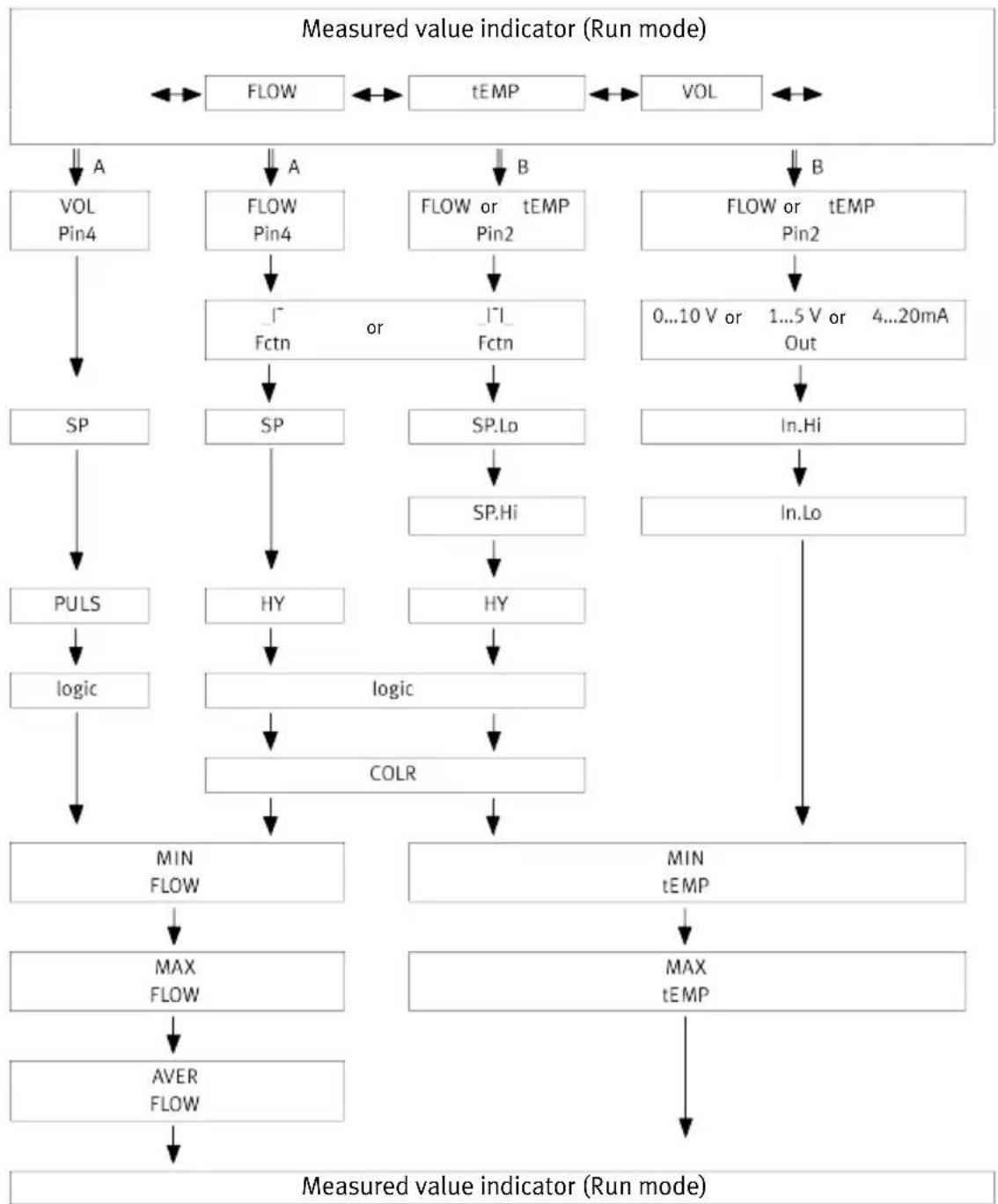
7.2 Displaying parameters in SHOW mode
Requirement: the sensor is ready for operation 7.1 Switching on the sensor in RUN mode.
flowchart
graph TD
    A["Measured value indicator (Run mode)"] --> B["Flow"]
    B --> C["tEMP"]
    C --> D["VOL"]
    D --> E["A"]
    E --> F["VOL Pin4"]
    F --> G["SP"]
    G --> H["PULS"]
    H --> I["logic"]
    I --> J["MIN FLOW"]
    J --> K["MAX FLOW"]
    K --> L["VER FLOW"]
    L --> M["Measured value indicator (Run mode)"]

    subgraph Run mode
        N["A"] --> O["FLOW"]
        P["B"] --> Q["FLOW or tEMP Pin2"]
        R["B"] --> S["FLOW or tEMP Pin2"]
        T["A"] --> U["FLOW Pin4"]
        V["B"] --> W["FLOW or tEMP Pin2"]
        X["B"] --> Y["0...10V or 1...5V or 4...20mA Out"]
        Z["In.Hi"] --> AA["In.Lo"]
    end

    subgraph Output Mode
        AB["SP"] --> AC["SP"]
        AD["SP,Lo"] --> AE["SP,Hi"]
        AF["HY"] --> AG["Logic"]
        AH["COLR"] --> AI["Max FLOW"]
        AJ["MIN FLOW"] --> AK["MAX FLOW"]
        AL["MIN tEMP"] --> AM["MAX tEMP"]
    end
Fig. 8: Menu structure SHOW mode
| Symbol Meaning | |
| ↔ ↓ | [A] key or [B] key |
| || | Double-click [A] key or [B] key |
Tab. 13: Symbols in the menu structure
7.2.1 Starting SHOW mode
Requirement: the sensor is ready for operation and is in RUN mode.
Commissioning
- Depending on the switching output, press the [A] or [B] key twice.
The sensor is in SHOW mode. The first parameter set is displayed.
- Press the [A] or [B] key to display the next parameter.
The other parameters of the selected switching output are displayed.
- Press the [A] or [B] to switch to RUN mode.
7.2.2 Show and reset minimum value/maximum value
Requirement: the sensor is in the SHOW mode.
- Depending on the switching output, press the [A] or [B] key several times.
The minimum value is displayed.
→ 'MIN'/'l/Min' or 'MIN'/'°C' flashes.
i
If no other key is pressed, the display remains permanent (no Timeout).
- Press the [Edit] key.
The minimum value is reset.
- Press the [A] or [B] key.
The maximum value is displayed.
'MAX'/'l/Min' or 'MAX'/'°C' flashes.
- Press the [Edit] key.
The maximum value is reset.
- Press the [A] or [B] key.
The mean value display or RUN mode is displayed.
7.2.3 Display mean value and reverse related filter time constants
Requirement: the sensor is in the SHOW mode.
- Press the [A] key several times.
The averaged flow rate value is displayed.
'AYER'/'l/Min' flashes.
i
If no other key is pressed, the display remains permanent (no Timeout).
- Press the [Edit] key.
The value of the filter time constant is changed (650 ms, 1200 ms, 2500 ms).
- Press the [A] key.
The RUN mode is displayed.
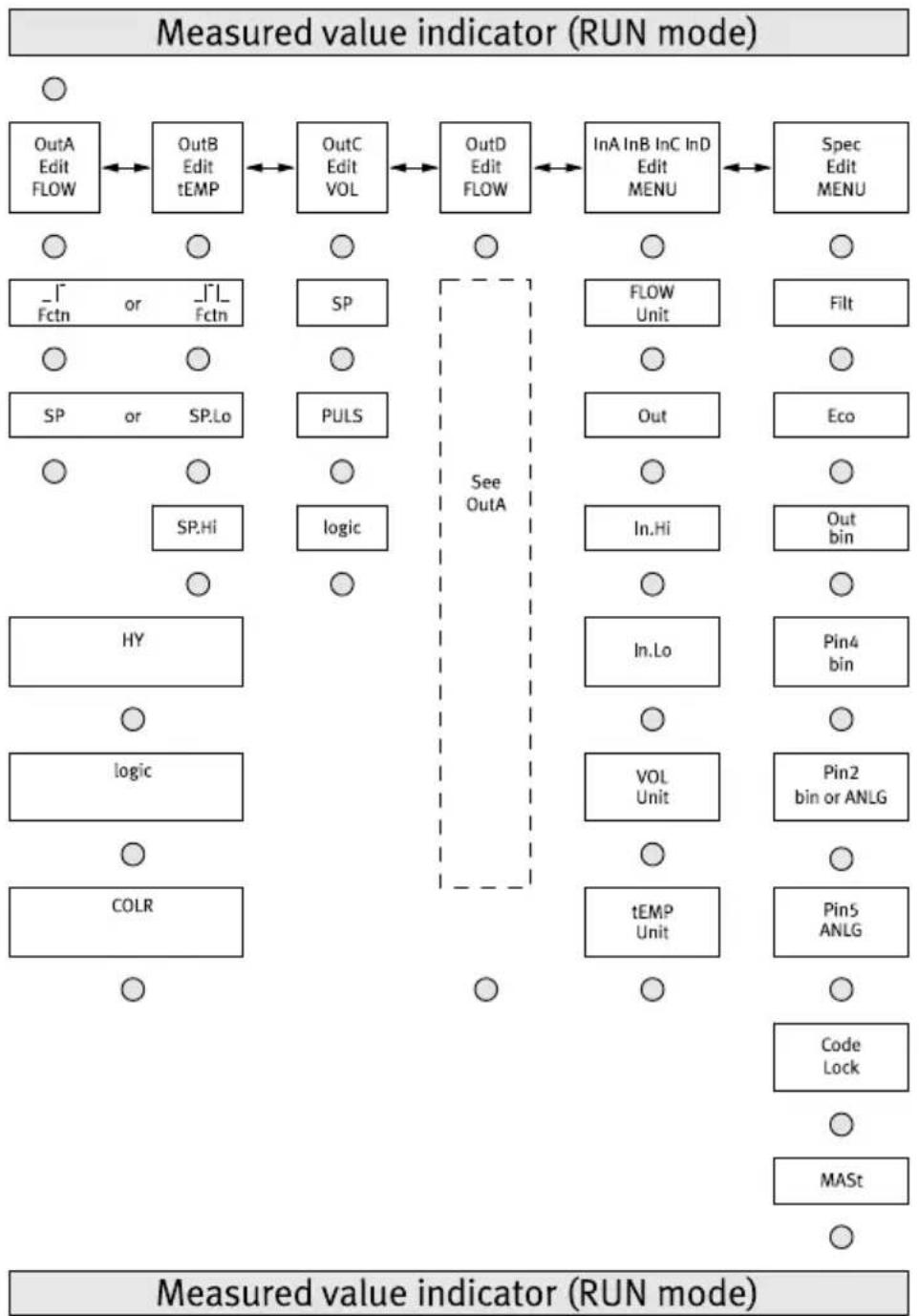
7.3 Configuring the sensor in EDIT mode
The figure below shows the complete menu structure. Some menu options or setting values are not applicable depending on the product variant and the selected switching function.
flowchart
graph TD
    A["OutA Edit FLOW"] <--> B["OutB Edit tEMP"]
    B <--> C["OutC Edit VOL"]
    C <--> D["OutD Edit FLOW"]
    D <--> E["InA InB InC InD Edit MENU"]
    E <--> F["Spec Edit MENU"]

    G["SP or SP.Lo"] --> H["SP"]
    I["SP.Hi"] --> J["logic"]

    K["HY"] --> L["logic"]

    M["COLR"] --> N["COLR"]

    O["FLOW Unit"] --> P["Out"]
    Q["In.Hi"] --> R["In.Lo"]
    S["VOL Unit"] --> T["tEMP Unit"]

    U["Filt"] --> V["Eco"]
    W["Eco"] --> X["Out bin"]

    Y["Pin4 bin"] --> Z["Pin2 bin or ANLG"]
    AA["Pin5 ANLG"] --> AB["Code Lock"]
    AC["MASt"] --> AD["MASt"]

    style G fill:#f9f,stroke:#333
    style I fill:#f9f,stroke:#333
    style K fill:#f9f,stroke:#333
    style M fill:#f9f,stroke:#333
    style O fill:#f9f,stroke:#333
    style U fill:#f9f,stroke:#333
    style V fill:#f9f,stroke:#333
    style W fill:#f9f,stroke:#333
    style X fill:#f9f,stroke:#333
    style Y fill:#f9f,stroke:#333
    style Z fill:#f9f,stroke:#333
    style AA fill:#f9f,stroke:#333
    style AB fill:#f9f,stroke:#333
    style AC fill:#f9f,stroke:#333
    style AD fill:#f9f,stroke:#333
Fig. 9: EDIT mode menu structure
| Symbol Meaning | |
| [Edit] key | |
| [A] key or [B] key |
Tab. 14: Symbols in the menu structure
| Parameter1) | Adjustable values Factory setting | |
| ‘SP’ with flow measurement | 5 ... 100% Full Scale2) | 60% Full Scale |
| ‘SP.Lo’ with flow measurement | 5 ... 99% Full Scale 60% Full Scale | |
| ‘SP.Hi’ with flow measurement | 5.5 ... 100% Full Scale 70% Full Scale | |
| ‘HY’ with flow measurement | 0 ... 90% Full Scale 0.5% Full Scale | |
| ‘SP’ with temperature measurement | 1 ... 90% Full Scale 40% Full Scale | |
| ‘SP.Lo’ with temperature measurement | 1 ... 89.5% Full Scale 40% Full Scale | |
| ‘SP.Hi’ with temperature measurement | 1.5 ... 90% Full Scale 60% Full Scale | |
| ‘HY’ with temperature measurement | 0 ... 80% Full Scale 0.5% Full Scale | |
| ‘logic’ NO, NC N/O | ||
| ‘COLR’ bLUE, R.ON, R.OFF | bLUE | |
| ‘SP’ with volume measurement | Setting range of ‘SP’ with volume measurement → 12 Technical data | SFAW-32-...: 32.0 l SFAW-100-...: 100.0 l |
| ‘PULS’ 10 ... 1000 MSEC | 100 MSEC | |
| ‘FLOW’ ‘Unit’ l/min, l/h, | CFM, GPM l/min | |
| ‘Out’ 0 ... 10 V, 1 ... 5 V, | 4 ... 20 MA 0...10 V | |
| ‘In.Hi’ | 10 ... 100% Full Scale | 100% Full Scale |
| ‘In.Lo’ 0 ... 90% Full Scale | 0% Full Scale | |
| ‘VOL’ ‘Unit’ | Ltr, M^3 (m3), CFt, GAL | Ltr |
| ‘tEMP’ ‘Unit’ | °C, °F | °C |
| ‘Filt’ | 100, 150, 300, 650, 1200, 2500, 5000, 10000 MSEC | 150 MSEC |
| ‘Eco’ | di.ON, 5, 10, 20, 40, 80, 160, 320, 640 s | di.ON |
| ‘bin’ ‘Out’ | PNP, NPN | PNP |
| ‘Pin4’ ‘bin’ | FLOW, VOL | FLOW |
| ‘Pin2’ ‘bin’ or ‘ANLG’ | FLOW, tEMP | FLOW |
| ‘Pin5’ ‘ANLG’ FLOW, tEMP | FLOW | |
| ‘Code’ ‘Lock’ OFF, 1 ... 99 | 99 OFF | |
| ‘MASt’ OFF, ON OFF |
1) All parameters of the complete menu structure are listed. Some menu options or setting values are not applicable depending on the product variant and the selected switching function.
2) The values refer to the applicable measuring range.
Tab. 15: Adjustable values and factory setting
7.3.1 Entering the security code
Requirement: the sensor is ready for operation and is in RUN mode.
- Press the [Edit] key.
The EDIT mode is active.
With security code activated: 'Lock' flashes.
-
Enter the security code with the [A] or [B] key.
-
Press the [Edit] key.
‘OutA’ flashes.
7.3.2 Setting the switching characteristics of the switching outputs
7.3.2.1 Set flow rate monitoring or temperature monitoring
i
The procedure for setting the flow monitoring at the switching signal OutA or switching signal OutD is the same. In the following, the procedure for the switching signal OutA is described.
The temperature monitoring can only be set for the switching signal OutB.
Requirement: the sensor is in the EDIT mode. 'OutA' flashes.
- Press the [Edit] key.
‘_I’ or ‘_I’ is displayed.
→ ‘Fctn’ flashes.
-
Select the switching function with the [A] or [B] key.
-
Press the [Edit] key.
‘SP’ or ‘SP.Lo’ flashes.
-
Set the value for the switching point with the [A] or [B] key.
-
Press the [Edit] key.
With window comparator switching function only: 'SP.Hi' flashes.
- For window comparator switching function only:
-Set the value for the switching point with the [A] or [B] key.
- Press the [Edit] key.
'HY' flashes.
-
Set the value for the hysteresis with the [A] or [B] key.
-
Press the [Edit] key.
'logic' flashes.
-
Select the switching element function with the [A] or [B] key.
-
Press the [Edit] key.
→ 'COLR' flashes.
-
Select the setting for the colour change with the [A] or [B] key.
-
Press the [Edit] key.
The RUN mode is displayed.
7.3.2.2 Set volume monitoring
i
The volume monitoring can only be set for the OutC switching signal.
The maximum pulse length depends on the magnitude of the threshold value and is automatically limited.
Requirement: the sensor is in the EDIT mode. 'OutA' flashes.
-
Use the [A] or [B] to select 'OutC'.
-
Press the [Edit] key.
'SP' flashes.
-
Set the value for the switching point with the [A] or [B] key.
-
Press the [Edit] key.
‘PULS’ flashes.
-
Select the pulse length with the [A] or [B] key.
-
Press the [Edit] key.
'logic' flashes.
-
Select the switching element function with the [A] or [B] key.
-
Press the [Edit] key.
The RUN mode is displayed.
7.3.3 Setting display units and analogue output
Requirement: the sensor is in the EDIT mode. 'OutA' flashes.
-
Use the [A] or [B] key to select 'InA InC InD InB'.
-
Press the [Edit] key.
'FLOW'/'Unit' flashes.
-
Select the display unit for the flow measurement with the [A] or [B] key.
-
Press the [Edit] key.
‘Out’ flashes.
-
Select the output signal with the [A] or [B] key.
-
Press the [Edit] key.
In.Hi'/'%' flashes.
-
Set the end value for scaling of the measuring range with the [A] or [B] key.
-
Press the [Edit] key.
In.Lo'/'%' flashes.
-
Set the start value for scaling of the measuring range with the [A] or [B] key.
-
Press the [Edit] key.
→ 'VOL'/'Unit' flashes.
Commissioning
-
Select the display unit for the volume measurement with the [A] or [B] key.
-
Press the [Edit] key.
‘tEMP’/‘Unit’ flashes.
-
Select the display unit for the temperature measurement with the [A] or [B] key.
-
Press the [Edit] key.
The RUN mode is displayed.
7.3.4 Changing sensor settings
Requirement: the sensor is in the EDIT mode. 'OutA' flashes.
-
Use the [A] or [B] to select the 'Spec' special menu.
-
Press the [Edit] key.
'Filt' flashes.
-
Use the [A] or [B] key to select the parameter or value.
-
Press the [Edit] key.
The set value is saved.
The next adjustable parameter flashes.
- Repeat steps 3 and 4 until all parameters are set → Fig. 9.
7.3.5 Replicating parameters
Requirement:
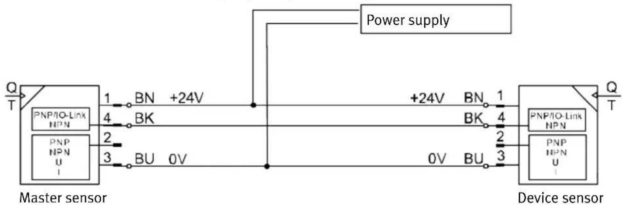
-The configured Master sensor is operational and in RUN mode.
- The Master sensor and the Device sensor are identical in terms of parameters, i.e. they have the same Device ID.
-The Master sensor is connected to the Device sensor Fig. 10.
-Parameterisation of the Device sensor via IO-Link must not be blocked.
- At the Device sensor the switching output at pin 4 is configured to PNP and is in unswitched status.
flowchart
graph LR
    A["Master sensor"] -->|Q T| B["PNP/IO-Link NPN"]
    A -->|1 4| C["PNP NPN U I"]
    A -->|2 3| D["BU 0V"]
    A -->|+24V| E["Power supply"]
    E --> F["Device sensor"]
    F -->|Q T| G["PNP/IO-Link NPN"]
    F -->|1 4| H["PNP NPN U I"]
    F -->|2 3| I["BU 0V"]
    F -->|+24V| J["Power supply"]
    J --> K["Device sensor"]
    style A fill:#f9f,stroke:#333
    style F fill:#ccf,stroke:#333
Fig. 10: Replicating parameters, using as an example SFAW-...PNLK-.../SFAW-...PNVBA-...
- Select the 'Spec' special menu at the Master sensor.
- Press the [Edit] button repeatedly until 'MASt' appears.
- Use the [A] or [B] key to select 'ON'.
- Press the [Edit] key.
→ 'REPL'/'RedY' appears.
Commissioning
5. Press the [A] or [B] key.
‘REPL’/‘RUN’ appears briefly.
The parameters are transmitted to the Device sensor.
→ 'REPL'/'RedY' appears.
If an error occurs, an error message appears.
6. If another sensor is to be configured, repeat step 5.
7. Press the [Edit] key.
The RUN mode is displayed.
7.4 Teach-in switching points in TEACH mode
The switching points for flow monitoring can be established in the TEACH mode 4.2.2.1 Switching functions.
Before the teach-in set the switching function to EDIT mode 7.3.2 Setting the switching characteristics of the switching outputs.
The procedure for teaching the OutA or OutD switching signal is in principle the same:
-OutA: press the [A] key.
- OutD: press the [B] key.
In the following, the procedure for the switching signal OutA is described.
Requirement: the sensor is ready for operation and is in RUN mode.
- Generate the flow rate for TP1.
- Press the [A] key and the [Edit] key.
With security code activated: [Lock] flashes.
‘t-IN’ flashes.
The measured value will then be applied as teach point (TP1).
3. Set the security code with the [A] or [B] key.
4. Press the [Edit] key.
5. Generate the flow rate for TP2.
6. Press the [A] key and the [Edit] key.
The measured value will then be applied as teach point (TP2).
The ‘SP’ switching point of the ‘SP.Lo’ and ‘SP.Hi’ switching points become valid.
The RUN mode is displayed.
7.5 Measure volume manually in RECORDER mode
Requirement: the sensor is ready for operation and is in RUN mode.
- Press the [A] and [B] keys simultaneously.
The current status of the measurement is displayed.
2. To start or stop the measurement, press the [A] key.
3. To reset the measurement, press the [B] key.
4. To exit RECORDER mode, press the [A] and [B] key simultaneously.
The RUN mode is displayed.
i
If the RECORDER mode is exited during a volume measurement, the measurement will continue in the background.
If the operating voltage is switched off, the measurement is aborted without saving the value.
8 Operation
8.1 Reset parameters to factory setting
i
If the factory settings are restored, the current settings will be lost.
- Switch off the operating voltage.
- Press and hold the [A] and [B] keys.
- Switch on the operating voltage.
- In addition to the [A] and [B] keys, press the [Edit] key.
‘Rsto PARM’ appears.
All parameters are reset to factory settings → Tab. 15 Adjustable values and factory setting.
9 Cleaning
- Switch off the power sources.
- If necessary, clean the outside of the sensor with media that are gentle on the material.
10 Fault clearance
| Malfunction / display Possible cause Remedy | |||
| Main display Sub-display | |||
| Settings cannot be edited;‘Lock’ appears. | Security code activated. | - Enter the security code.- If the security code cannot be found, restore factory settings→ 8.1 Reset parameters to fac-tory setting. | |
| ‘Er01’ ‘FAIL’ Sensor fault. | - Replace sensor. | ||
| ‘Er02’ ‘ASIC’ | |||
| ‘Er08’/‘FLOW’ | Instability in the flow rate. | - Ensure laminar flow rate. | |
| ‘----’ ‘Er08’/‘FLOW’ | - Instability in the flow rate.- Flow measuring range exceeded. | - Ensure laminar flow rate.- Maintain flow measuring range. | |
| ‘Er10’/‘FLOW’ | Flow measuring range exceeded. | - Maintain flow measuring range. | |
| ‘Er11’/‘tEMP’ | Temperature measuring range of the operating medium undershot. | - Maintain temperature measurement range. | |
| ‘Er12’/‘tEMP’ | Operating medium temperature measuring range exceeded. | - Maintain temperature measurement range. | |
| ‘Er17’/‘SUPL’ | Undervoltage. | - Apply permissible operating voltage. | |
| ‘Er20’/‘tEMP’ | Device temperature error. | - Check operating temperature and ambient temperature.- Check load conditions.- Check circuitry.- Replace sensor. | |
| ‘Er21’/‘SHRt’ | Short circuit at the switching output pin 4. | - Eliminate short circuit. | |
| ‘Er22’/‘SHRt’ | Short circuit at the switching output pin 2. | - Eliminate short circuit. | |
| ‘Err’/‘bUSY’ - IO-Link operation: Pin 4 is actively switched in the device sensor. | - Check settings of the device sensor. | ||
| ‘Err’/‘Id’ - IO-Link operation: device ID error. | - When replicating, use sensors with the same parameters with the same device ID. | ||
| ‘Err’/‘COMM’ - IO-Link communication error. | - Check settings of the device sensor.- Check line at pin 4. | ||
Tab. 16: Fault clearance
11 Removal
- Switch off the power sources.
- Disconnect connections from the sensor.
- Loosen the mountings.
i
If mounted into fixed piping, the sensor can be separated from the fluid connectors by removal of the clamps on the back 5.4 Changing fluid connector.
12 Technical data
| General | |
| Certification RCM compliance mark, c UL us - Listed | (OL) |
| Declaration of conformity | → www.festo.com/sp |
Tab. 17: General
| Input signal/measuring element SFAW-32-... SFAW | -100-... | ||
| Measured variable Flow rate, temperature | |||
| Flow direction unidirectional P1 → P2 | |||
| Measurement principle Flow rate: vortex | Temperature: PT1000 | ||
| Flow measuring range [l/min] 1.8 ... 32 5.0 ... 100 | |||
| Temperature measuring range [°C] | 0 ... 90 | ||
| Operating pressure | [MPa] | 0 ... 1.2 | |
| [bar] | 0 ... 12 | ||
| [psi] | 0 ... 174 | ||
| Information on operating pressure | [MPa] | max. 1.2 MPa at 40 °Cmax. 0.6 MPa at 90 °C | |
| [bar] | max. 12 bar at 40 °Cmax. 6 bar at 90 °C | ||
| [psi] | max. 174 psi at 40 °Cmax. 87 psi at 90 °C | ||
| Operating medium | Liquid media, neutral liquids, water | ||
| Information on the operating medium | Media with a kinematic viscosity ≤ 1.8 mm2/s[cSt] | ||
| Temperature of medium | [°C] | 0 ... 90 | |
| Ambient temperature | [°C] | 0 ... 50 | |
| Nominal temperature | [°C] | 23 | |
Tab. 18: Input signal/measuring element
| Output, general | ||
| Accuracy of zero point Flow rate ≤ 50% FS | [% FS] | ±2 |
| Accuracy of spread Flow rate ≥ 50% FS | [% FS] | ±3 |
Output, general
| Repetition accuracy of zero point Flow rate ≤ 50% FS | [% FS] ± 0.5 |
| Repetition accuracy of spread Flow rate ≥ 50% FS | [% FS] ± 1 |
| Accuracy of temperature [°C] ± 2 | |
| Temperature coefficient of spread [% FS/K] typ. ± 0.05 | |
Tab. 19: Output, general
Switching output
| Switching output 2 x PNP or 2 x NPN, switchable | |
| Switching function Threshold value comparator or window comparator, freely programmable | |
| Switching element function N/C contact or N/O contact, switchable | |
| Switch-on time [ms] 400 at filter time constant 150 ms | |
| Switch-off time [ms] 300 at filter time constant 150 ms | |
| Max. output current [mA] 100 | |
| Voltage drop [V] | ≤1.5 |
| Pull-down/pull-up resistor | PNP: integratedNPN: not integrated |
| Inductive protective circuit | Available |
Tab. 20: Switching output
| Analogue output | SFAW-32-... | SFAW-100-... | |
| Characteristic flow rate curve | [l/min] | 0 ... 32 | 0 ... 100 |
| Characteristic temperature curve | [°C] 0 ... 1 | 100 | |
| Current output characteristic curve | [mA] | 4 ... 20 | |
| Voltage output characteristic curve | [V] | 0 ... 10 or 1 ... 5, adjustable | |
| Rise time | [ms] 900 at filter time constant 150 ms | ||
| Max. load resistance of current output | [Ω] | 500 | |
| Min. load resistance at voltage output | [kΩ] | 15 | |
Tab. 21: Analogue output
Output, additional data
| Short circuit current rating Yes | |
| Overload protection Available |
Tab. 22: Output, additional data
Electronics
| Operating voltage range DC [V] 18 ... 30 | |
| Reverse polarity protection For all electrical connections | |
Tab. 23: Electronics
Electromechanics
| Electrical connection Straight plug, M12x1, 5-pin | |
| Max. connecting cable length [m] 30, for IO-Link operation 20 | |
Tab. 24: Electromechanics
Mechanics
| Mounting position any | |
| Housing material Reinforced polyamide | |
| Materials in contact with the media ETFE, PA6T/6I reinforced, EPDM, stainless steel | |
| Keypad material TPE-O | |
| Plug housing material | Brass, nickel-plated |
Tab. 25: Mechanics
Display/operation
| Display type | Illuminated LCD, blue | |
| Displayable units | l/min, l/h, US gal/min, cfm, l, m^3 , US gal, cft, °C, °F | |
| Threshold value setting range | [l] | 0.1 ... 1999.9 |
| Volume pulse | [m3] | 0.01 ... 199.99 |
| [cft] | 0.01 ... 199.99 | |
| [US gal] | 1 ... 19999 | |
| Hysteresis setting range | [% FS] | 0 ... 90 |
Tab. 26: Display/operation
Immission/Emission
| Storage temperature [°C]–20 ... 80 | |
| Degree of protection IP65 | |
| Protection class III |
Tab. 27: Immission/Emission
| IO-Link® SFAW-...-T-... SFAW without | Temperature measurement | |
| Protocol version Device V1.1 | ||
| Profile Smart Sensor Profile | ||
| Function classes Binary data channel (BDC)Process data variable (PDV)IdentificationDiagnosticsTeach channel | ||
| Communication mode COM2, 38.4 kbaud | ||
| Port class A | ||
| Process data length IN 5 bytes | 3 bytes | |
| Process data content IN | Flow monitoring: 2 bit BDCVolume monitoring: 1 bit BCTemperature monitoring: 1 bit BDCMeasured flow rate value: 14 bit PDVMeasured temperature value: 14 bit PDV | |
| Service data IN | Measured volume value: 32 bit PDV | |
| IODD, IO-Link device description | → www.festo.com | |
Tab. 28: IO-Link®
12.1 Technical data of UL/CSA certification
Electrical data and ambient conditions for UL/CSA
| Maximum input voltage 30 V DC, Class 2 | |
| Maximum input current | 0.26 A |
| Maximum power | 8 W |
| Maximum operating pressure | 12 bar |
| Maximum Ambient Temperature | 50 °C/122 °F |
| Pollution degree | 2 |
Electrical data and ambient conditions for UL/CSA
| Permissible humidity 93% | |
| Installation site for indoor use only | |
| Maximum installation height 2000 m |
Tab. 29: Electrical data and ambient conditions for UL/CSA
12.2 Hole patterns and dimensional drawings
12.2.1 Hole pattern for direct mounting
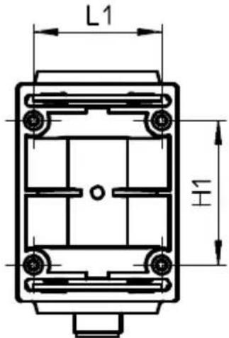
Fig. 11: Hole pattern for direct mounting
Hole pattern for direct mounting
| L1 [mm] 32 | |
| H1 [mm] 36 |
Tab. 30: Hole pattern for direct mounting
12.2.2 Hole pattern for wall mounting
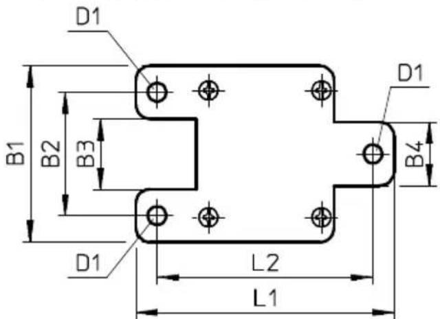
Fig. 12: Hole pattern for wall mounting
Hole pattern for wall mounting
| B1 [mm] 50 | |
| B2 [mm] 35 | |
| B3 [mm] 20 | |
| B4 [mm] 18 | |
| L1 [mm] 73.2 | |
| L2 [mm] 61.2 | |
| D1 [mm] ∅ 5.2 |
Tab. 31: Hole pattern for wall mounting
12.2.3 Dimensional drawing of customer-specific fluid connections
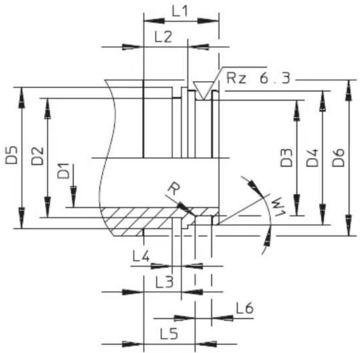
Fig. 13: Dimensional drawing of customer-specific fluid connections
Dimensional drawing of customer-specific fluid connections
| L1 [mm] 14.5 ±0.05 | |
| L2 [mm] 8.5 ±0.05 | |
| L3 [mm] 7.35 ±0.03 | |
| L4 [mm] 1.8 +0.1 | |
| L5 [mm] 10 ±0.05 | |
| L6 [mm] 3.2 +0.1 |
Dimensional drawing of customer-specific fluid connections
| D1 [mm] SFAW-32-...: 11 ±0.1 | SFAW-100-...:19 ±0.1 |
| D2 [mm] ∅23 ±0.1 | |
| D3 [mm] ∅22.2 ±0.05 | |
| D4 [mm] ∅25.9 -0.05 | |
| D5 [mm] ∅27.15 | f8 |
| D6 [mm] ∅30 -0.5 | |
| R [mm] 0.3 | |
| W1 [°] 30 |
Tab. 32: Dimensional drawing of customer-specific fluid connections
Copyright:
Festo SE & Co. KG
Ruiter Straße 82
73734 Esslingen
Germany
Phone:
+49 711 347-0
- FESTO
- Table of contents
- Applicable documents.... 5
- Safety....5
- Additional information....6
- Product overview.... 6
- Mounting.... 14
- Installation.... 18
- Commissioning....19
- Applicable documents
- Safety
- Safety instructions
- Intended use
- Training of qualified personnel
- UL/CSA certification
- WARNING
- Additional information
- Product overview
- Structure
- Function
- Operating statuses
- Switching outputs
- Switching functions
- Window comparator in the flow measurement for OutA or OutD and in the temperature measurement for OutB
- Function Normally open contact (N/O) Normally closed (N/C contact)
- Colour change
- Volume pulse
- Setting of N/O contact (NO) Setting N/C contact (NC)
- Analogue output
- Analogue signal
- Output signal
- Scaling of the analogue signal
- Filter
- Functional principle
- Security code
- Minimum value and maximum value
- Mounting
- Inlet situation and outlet situation
- Mounting
- Mounting position/inflow
- Mounting
- Installing sensor without mounting accessories
- Mounting sensor with wall mounting
- Tubing sensor
- Changing fluid connector
- Installation
- Installation, electrical
- Risk of injury due to electric shock.
- Commissioning
- Switching on the sensor in RUN mode
- Displaying parameters in SHOW mode
- Starting SHOW mode
- Commissioning
- Show and reset minimum value/maximum value
- i
- Display mean value and reverse related filter time constants
- Configuring the sensor in EDIT mode
- Entering the security code
- Setting the switching characteristics of the switching outputs
- Set flow rate monitoring or temperature monitoring
- Set volume monitoring
- Setting display units and analogue output
- Changing sensor settings
- Replicating parameters
- Requirement:
- Press the [A] or [B] key.
- If another sensor is to be configured, repeat step 5.
- Press the [Edit] key.
- Teach-in switching points in TEACH mode
- Set the security code with the [A] or [B] key.
- Press the [Edit] key.
- Generate the flow rate for TP2.
- Press the [A] key and the [Edit] key.
- Measure volume manually in RECORDER mode
- To start or stop the measurement, press the [A] key.
- To reset the measurement, press the [B] key.
- To exit RECORDER mode, press the [A] and [B] key simultaneously.
- Operation
- Reset parameters to factory setting
- Cleaning
- Removal
- Technical data
- Technical data of UL/CSA certification
- Hole patterns and dimensional drawings
- Hole pattern for direct mounting
- Hole pattern for wall mounting
Brand : Festo
Model : SFAW-32T-X-E-PNLK-PNVBA-M12
Category : Measurement