
VTOP - Industrial valve Festo - Free user manual and instructions
Find the device manual for free VTOP Festo in PDF.


| Product Type | Valve Terminal |
| Brand | Festo |
| Model | VTOP |
| Dimensions (HxWxD) | 150 x 80 x 60 mm |
| Weight | Approx. 0.5 kg |
| Operating Pressure | 3 to 8 bar |
| Voltage | 24 V DC |
| Number of Valves | Up to 16 (depending on configuration) |
| Valve Type | Pneumatic solenoid valves |
| Protection Class | IP65 |
| Ambient Temperature | -5°C to 50°C |
| Materials | Aluminum, plastic |
| Functions | Pneumatic control, electrical connection via multipole or fieldbus |
| Maintenance | Periodic cleaning, check for leaks |
| Safety | Use only with compressed air, observe pressure limits |
| Spare Parts | Coils, seals, gaskets available |
| Repairability | Modular design, individual valve replacement possible |
| Connection | Sub-D or fieldbus (e.g., Profibus, Ethernet) |
| Certifications | CE, RoHS |
| Included Accessories | Mounting brackets, sealing plugs |
| Additional Information | Used in automation systems |
Frequently Asked Questions - VTOP Festo
User questions about VTOP Festo
0 question about this device. Answer the ones you know or ask your own.
Ask a new question about this device
Download the instructions for your Industrial valve in PDF format for free! Find your manual VTOP - Festo and take your electronic device back in hand. On this page are published all the documents necessary for the use of your device. VTOP by Festo.
USER MANUAL VTOP Festo
natural_image
Technical line drawing of a mechanical component with no visible text or symbolsFESTO
Operating instruction
Translation of the original instructions
Table of contents
1 About this document.... 5
1.1 Applicable documents....5
1.2 Product designation.... 5
1.3 Product labelling....6
1.4 Specified standards....6
2 Safety....6
2.1 Safety instructions....6
2.2 Intended use.... 6
2.2.1 Permissible components....7
2.3 Training of qualified personnel....7
3 Additional information....7
4 Product overview.... 8
4.1 Structure....8
4.1.1 Valve terminal VTOP....8
4.1.2 Adapter plate VABA....9
4.1.3 Volume booster VOGM.... 14
4.1.4 Filter regulator PCRI.... 15
4.1.5 Fail safe module VOGI....16
4.1.6 Flange module for safety functions VABP 17
4.1.7 End plate VABE....20
4.1.8 Adapter kit VABA....20
4.1.9 Mounting kit VAME....21
4.2 Module overview.... 21
4.3 Function.... 22
5 Assembly....23
5.1 Assembling....23
5.1.1 Rules for set-up.... 23
5.2 Attachment.... 24
5.2.1 Attaching valve terminal VTOP....24
5.2.2 Attaching positioner.... 24
5.3 Mounting accessories.... 25
5.3.1 Mounting pressure gauge.... 25
5.3.2 Removing pressure gauge.... 25
5.3.3 Mounting control valve....25
5.3.4 Mounting adapter kit VABA.... 27
5.3.5 Install the VAME mounting kit.... 28
6 Installation.... 29
6.1 Installation, pneumatic....29
6.2 Earthing.... 29
7 Commissioning....29
8 Operation.... 30
8.1 Setting the output pressure.... 30
8.2 Adjusting volume boost.... 30
9 Maintenance.... 30
9.1 Changing filter.... 30
9.2 Cleaning.... 30
10 Fault clearance.... 31
11 Modification.... 31
11.1 Converting valve terminal VTOP.... 31
11.2 Reversing effective direction.... 32
12 Technical data....33
12.1 Valve terminal VTOP.... 33
12.2 Adapter plate VABA....34
12.3 Volume booster VOGM.... 35
12.4 Filter regulator PCRI....36
12.5 Fail safe module VOGI....37
12.6 Flange module for safety functions VABP 38
12.7 End plate VABE.... 38
12.8 Adapter kit VABA.... 39
1 About this document
1.1 Applicable documents
□□
All available documents for the product→ www.festo.com/sp.
1.2 Product designation
The following products are designated as follows in this document.
| Product Product designation in the document | |
| Sub-baseVABP-C13-100HFT...-F90-... | Flange module for safety functions VABP |
| Pneumatic valveVOGI-F100FS-T32H-M-F90 | Fail safe module VOGI |
| Pneumatic valveVOGM-FD100 -...- M-F90 | Volume booster VOGM |
| Filter regulatorPCRI-100-F90-12-..-T3 | Filter regulator PCRI |
| Adapter plateVABA-C13-100-...-F90-... | Adapter plate VABA |
| Adapter plateVABA-C13-G14 | Adapter kit VABA |
| End plateVABE-C13-100-F90-DU | End plate VABE |
| Assembly kitVAME-C13-K | Mounting kit VAME |
Tab. 1: Product designation in the document
1.3 Product labelling
The product labelling is located on the side.

Fig. 1: Product labelling
1.4 Specified standards
| Version | ||
| DIN EN 60068-2-6:2008-10 VDI/VDE 3845-1:2010-09 | ||
| DIN EN 60068-2-27:2010-02 VDI/VDE 3847-2:2016-10 | ||
| ISO 8573-1:2010 – | ||
Tab. 2: Standards specified in the document
2 Safety
2.1 Safety instructions
- Only use the product in its original condition without unauthorised modifications.
-Only use the product if it is in perfect technical condition.
-Observe the identifications on the product.
-Take into account the ambient conditions at the location of use.
- Before working on the product, switch off the compressed air supply and lock it to prevent it from being switched on again.
- Store and transport the product in its original packaging. Observe the weight, the dimensions and the ambient conditions.
- Store the product in a cool, dry environment protected from UV and corrosion. Keep storage times short.
- Have the product repaired by the Festo repair service only.
2.2 Intended use
The valve terminal is intended for operating pneumatic drives in combination with a positioner in process automation and for implementing additional pneumatic functions.
2.2.1 Permissible components
The product may only be used in combination with permissible components. The documentation of the components used must be observed.
| Festo products Third-party products | |
| Pneumatic drives | |
| Semi-rotary drive DFPD-240 ... -2300 Third-party drives with interface in accordance with VDI/VDE 3845 or as peripherals on all pneumatic drives. | |
| Semi-rotary drive DAPS-0180-...-1920 | |
| Linear drive DFPI-160 ... -320-...-E-NB3VM12 | |
| Positioner | |
| Positioner CMSH Positioner with interface in accordance with VDI/VDE 3847-2 | |
| Control valves | |
| Solenoid valve VOFC Control valves with interface in accordance with:– VDI/VDE 3845-1 (NAMUR)– VDI/VDE 3847 | |
Tab. 3: Permissible components
2.3 Training of qualified personnel
Work on the product may only be carried out by qualified personnel who can evaluate the work and detect dangers. The qualified personnel have knowledge and experience in process automation.
3 Additional information
- Contact the regional Festo contact if you have technical problems → www.festo.com. - Accessories and spare parts → www.festo.com/catalogue.
4 Product overview
4.1 Structure
4.1.1 Valve terminal VTOP

Fig. 2: Valve terminal VTOP, sample design
1 Adapter plate VABA
5 End plate VABE
2 Volume booster VOGM
A Side A
3 Fail safe module VOGI
B Side B
4 Filter regulator PCRI
4.1.2 Adapter plate VABA
The adapter plate VABA is the interface between valve terminal VTOP, pneumatic drive and positioner. Various adapter plates are available, depending on the pneumatic drive.
| VABA-C-100 -1-F90-G12 -1-F90-G12- | G14 | -2-F90-G12 -2-F90-G12-G14 | ||
| Semi-rotary drives | ||||
| Semi-rotary driveDFPD-240-...-900 | -X-- | |||
| Semi-rotary driveDFPD-240-...-900-...-C-VDE2 | X--- | |||
| Semi-rotary driveDFPD-1200-...-2300 | ---X | |||
| Semi-rotary driveDFPD-1200-...-2300-...-C-VDE2 | --X- | |||
| Semi-rotary driveDAPS-0180-...-0720 | -X-- | |||
| Semi-rotary driveDAPS-0960-...-1920 | ---X | |||
| Third-party drives | ||||
| With interface in accordance with VDI/VDE 3845-1 | -X-X | |||
Tab. 4: Adapter plates VABA for pneumatic drives
4.1.2.1 Adapter plate VABA-C13-100-1-F90-G12

Fig. 3: VABA-C13-100-1-F90-G12, view A
1 Earth terminal
4 Module interface
2 Pneumatic port: supply air (1)
5 Thread
3 Interface for DFPD-...-C-VDE2
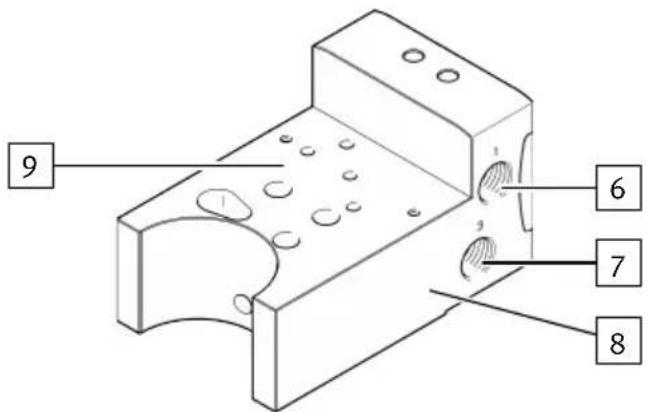
Fig. 4: VABA-C13-100-1-F90-G12, view B
6 Pneumatic port: supply air (1)
8 Product labelling
7 Pneumatic port: exhaust air (3)
9 Interface in accordance with VDI/VDE 3847-2 for positioner
4.1.2.2 Adapter plate VABA-C13-100-2-F90-G12
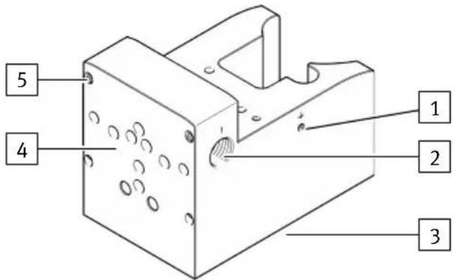
Fig. 5: VABA-C13-100-2-F90-G12, view A
1 Earth terminal
2 Pneumatic port: supply air (1)
3 Interface for DFPD-...-C-VDE2

Fig. 6: VABA-C13-100-2-F90-G12, view B
6 Pneumatic port: supply air (1)
7 Pneumatic port: exhaust air (3)
4 Module interface
5 Thread
4 Module interface
4 Module interface
4 Module interface
4 Module interface
4 Module interface
4.1.2.3 Adapter plate VABA-C13-100-1-F90-G12-G14
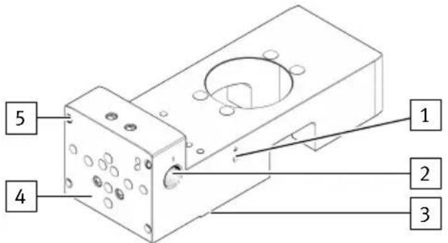
Fig. 7: VABA-C13-100-1-F90-G12-G14, view A
1 Earth terminal
2 Pneumatic port: supply air (1)
3 Interface in accordance with VDI/VDE 3845-1 for pneumatic drive

Fig. 8: VABA-C13-100-2-F90-G12-G14, view B
6 Pneumatic port: supply air (1)
7 Pneumatic port: exhaust air (3)
8 Pneumatic port: working air (2 and 4)
4 Module interface
5 Thread
9 Product labelling
10 Interface in accordance with VDI/VDE 3847-2 for positioner
4.1.2.4 Adapter plate VABA-C13-100-2-F90-G12-G14
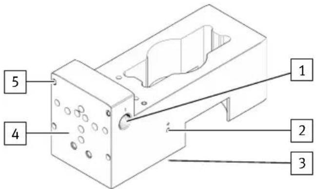
Fig. 9: VABA-C13-100-2-F90-G12-G14, view A
1 Pneumatic port: supply air (1)
2 Earth terminal
3 Interface in accordance with VDI/VDE 3845-1 for pneumatic drive
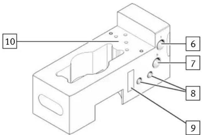
Fig. 10: VABA-C13-100-2-F90-G12-G14, view B
6 Pneumatic port: supply air (1)
7 Pneumatic port: exhaust air (3)
8 Pneumatic port: working air (2 and 4)
4 Module interface
5 Thread
4 Module interface
4 Module interface
4 Module interface
4 Module interface
4 Module interface
4.1.3 Volume booster VOGM
The VOGM volume booster is used if the process valve's operating times have to be reduced. The direct integration of the VOGM volume booster in the control loop means that the pneumatic drive can be precisely positioned even with fast response times.
The response sensitivity for initialisation is set using a flow control screw for a single-acting module and two flow control screws for a double-acting module 8.2 Adjusting volume boost.

Fig. 11: VOGM-FD100-T33H-M-F90, view A
1 Blanking plug for flow control screw duct 2
2 Interface with modules, page A
3 Flow control screw blanking plug duct 4 (only VOGM-FD100-T33H-M-F90, double-acting)
4 Thread
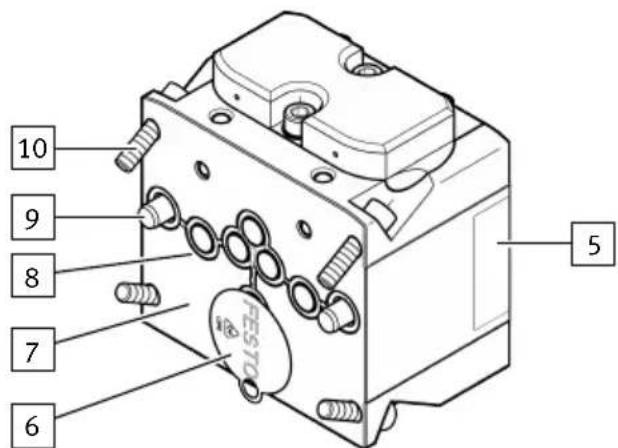
Fig. 12: VOGM-FD100-T33H-M-F90, view B
5 Product labelling
6 Transportation lock
7 Interface with modules, page B
8 Seal
9 Cylindrical pin
10 Screw
4.1.4 Filter regulator PCRI
The filter regulator PCRI smoothes out pressure fluctuations and regulates the compressed air to the set output pressure 8.1 Setting the output pressure. The integrated filter removes dirt particles from the compressed air. The filter can be replaced if contaminated 9.1 Changing filter. A pressure gauge can be mounted to display the set output pressure 5.3.1 Mounting pressure gauge. The set output pressure can be locked to prevent unauthorised adjustment www.festo.com/catalogue.
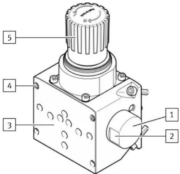
Fig. 13: PCRI-100-F90-12 -...- T3, view A
1 Filter covering
2 Spanner flat
3 Interface with modules, side A
4 Thread
5 Rotary knob, lockable

Fig. 14: PCRI-100-F90-12 -...- T3, view B
6 Product labelling
7 Pressure gauge connection via plug screw
8 Transportation lock
9 Interface with modules, side B
10 Seal
11 Cylindrical pin
12 Screw
4.1.5 Fail safe module VOGI
The fail-safe module VOGI is used to achieve a defined end position in the event of a compressed air failure. If the compressed air supply at the adapter plate VABA pneumatic port fails, the fail safe module VOGI automatically depressurises duct 2 and duct 4 is pressurised with the compressed air volume of the defined drive chamber via the predefined redundant supply air pneumatic port (1) on the fail safe module VOGI. The defined end position depends on the orientation of the reversing plate in the end plate VABE 4.1.7 End plate VABE.

Fig. 15: VOGI-F100FS-T32H-M-F90, view A
1 Pneumatic port for supply air (1)
2 Interface with modules, side A
3 Thread

Fig. 16: VOGI-F100FS-T32H-M-F90, view B
4 Product labelling
5 Transportation lock
6 Interface with modules, side B
7 Seal
8 Cylindrical pin
9 Screw
4.1.6 Flange module for safety functions VABP
The flange module VABP for safety functions serves as an interface for safe venting in an emergency. The use of control valves makes it possible to implement safety functions (HFT 0, HFT 1) for safe venting with different safety architectures. Exhaust duct 2 of the mounted control valve is always directly connected to duct 2 of the pneumatic drive, independently of other modules and module positions of the valve terminal VTOP.
i
The flange module for safety functions VABP only provides the interface for various safety architectures and is not a safety device.
The safety-related values are dependent on the specific control valve and the selected safety architecture.
| VABP-C13 -100HFT...-F90-VDE1E -100HFT0-F90-VDE1 | ||
| Solenoid valves | ||
| VOFC-LT-...-FGP14-... X – | ||
| VOFC-LT-...-FG14-... – X | ||
Tab. 5: Flange module for safety functions VABP for solenoid valves
4.1.6.1 VABP-C13-100HFT0-F90-VDE1E

Fig. 17: VABP-C13-100HFT0-F90-..., view A
1 Covering for control valve interface in accordance with VDI/VDE 3847, top
2 Control valve interface in accordance with VDI/VDE 3847, side
3 Interface with modules, side A
4 Thread
Product overview
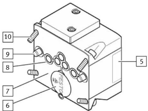
Fig. 18: VABP-C13-100HFT0-F90-..., view B
5 Product labelling
6 Transportation lock
7 Interface with modules, side B
8 Seal
9 Cylindrical pin
10 Screw
1 Control valve interface in accordance with VDI/VDE 3847, top
2 Control valve interface in accordance with VDI/VDE 3847, side
3 Interface with modules, side A
4 Screw

Fig. 20: VABP-C13-100HFT1-F90-..., view B
5 Product labelling
6 Transportation lock
7 Interface with modules, side B
8 Seal
9 Cylindrical pin
10 Screw
1 Supply air return (1) control valve
2 Control valve interface in accordance with VDI/VDE 3845-1
3 Interface with modules, side A
4 Screw
5 Product labelling
6 Transportation lock
7 Interface with modules, side B
8 Seal
9 Cylindrical pin
10 Screw
4.1.7 End plate VABE
The end plate VABE is the terminating module of the valve terminal VTOP and must generally be used. A reversible reversing plate is located inside the end plate VABE. The orientation of the reversing plate defines the effective direction and, at the same time, the end position if the compressed air supply fails in the double-acting pneumatic drive.

Fig. 23: VABE-C13-100-F90-DU, view A
1 Display of effective direction: - double arrow parallel 2-2/4-4, factory setting - arrows crossed 2-4/4-2

2 Product labelling
3 Cylindrical pin
4 Transportation lock
5 Reversing plate
6 Screw
4.1.8 Adapter kit VABA
The adapter kit VABA is the interface between the valve terminal VTOP and the externally mounted positioner.
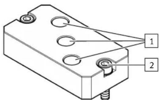
1 Pneumatic ports
2 Screw
4.1.9 Mounting kit VAME
The mounting kit VAME can be mounted on the adapter plate VABA-C13-100-...-F90-G12-G14 and the end plate VABE if the valve terminal VTOP is mounted externally.

Fig. 26: Mounting kit VAME-C13-K
4.2 Module overview
| Module Function | |
| Adapter plate VABA1) | |
| VABA-C13-100-1-F90-G12 Interface between valve terminal VTOP, pneumatic drive and positioner | |
| VABA-C13-100-2-F90-G12 | |
| VABA-C13-100-1-F90-G12-G14 | |
| VABA-C13-100-2-F90-G12-G14 | |
| Adapter kit VABA | |
| VABA-C13-G14 Interface for the air connection from the VTOP valve terminal to the positioner | |
| Volume booster VOGM | |
| VOGM-FD100-M33E-M-F90 Boosting the compressed air flow rate specified by the positioner for single-acting pneumatic drives | |
| VOGM-FD100-T33H-M-F90 Boosting the compressed air flow rate specified by the positioner for double-acting pneumatic drives | |
| Filter regulator PCRI | |
| PCRI-100-F90-12-C-T3 Filtering 5 μm and regulation of the filtered compressed air | |
| PCRI-100-F90-12-E-T3 Filtering 40 μm and regulation of the filtered compressed air | |
| Fail safe module VOGI | |
| VOGI-F100FS-T32H-M-F90 Reaching a defined end position in the event of pressure failure for double-acting applications | |
| Flange module for safety functions VABP | |
| VABP-C13-100HFT0-F90-VDE1E Interface for safe venting in different safety architectures for single-acting applications | |
| VABP-C13-100HFT1-F90-VDE1E | |
| VABP-C13-100HFT0-F90-VDE1 | |
| End plate VABE | |
| VABE-C13-100-F90-DU Reversal of the effective direction with double-acting pneumatic drives | |
| Mounting kit VAME | |
| VAME-C13-K Interface for externa mounting | |
1) Not included in the scope of delivery.
Tab. 6: Module overview
4.3 Function
The valve terminal VTOP has a modular design and, depending on the modules used, the following additional pneumatic functions can be implemented:
-Compressed air regulation and filtering
- Volume flow boosting
- Reaching a defined end position in the event of a pressure failure
-Safe venting
-Direction reversal for double-acting pneumatic drives
The valve terminal VTOP, the pneumatic drive and the positioner can be directly mechanically and pneumatically connected by the adapter plate VABA. The valve terminal VTOP can also be mounted externally on a mounting surface provided by the customer with the mounting kit VAME. When mounted externally, the positioner is mounted either on the VTOP or directly on the pneumatic drive.
The compressed air is then connected between the valve terminal VTOP and the positioner with the adapter kit VABA.
The compressed air is supplied via the pneumatic ports of the adapter plate VABA. The AiRing function distributes the compressed air internally. This eliminates the need for complex tubing or piping for the individual modules.
5 Assembly
5.1 Assembling
5.1.1 Rules for set-up
Rules for set-up
| Number of modules Mini | mum: adapter plate VABA + 1 module + end plate VABE |
| Maximum:1) Adapter plate VABA + 3 modules + end plate VABEMaximum for external mounting:2) VABA + 7 modules + end plate VABE | |
| Module sequence VABE a | adapter plate always as the first module |
| Fail safe module VOGI after a volume booster VOGM | |
| End plate VABE is always the last module | |
| Impermissible module combinations | Fail safe module VOGI and flange module for safety functions VABP |
| Identical modulesException: flange modules for safety functions VABP | |
| Different filter regulators PCRI |
1) If the maximum number of modules is exceeded, additional measures are required to comply with vibration resistance and shock resistance.
2) If the maximum number of modules is exceeded, additional measures are required to comply with vibration resistance and shock resistance.
Tab. 7: Rules for set-up
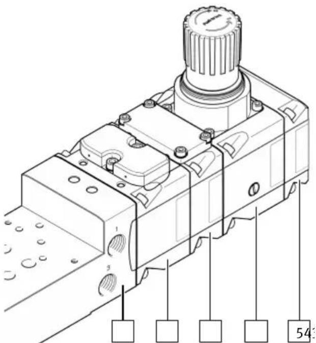
1 Adapter plate VABA
2 Volume booster VOGM
3 Fail safe module VOGI
4 Filter regulator PCRI
5 End plate VABE
Fig. 27: Sample structure
5.2 Attachment
5.2.1 Attaching valve terminal VTOP
The valve terminal VTOP is attached to the pneumatic drive via the adapter plate VABA.
- Mount the adapter plate VABA to the pneumatic drive
→ Assembly instructions for adapter plate VABA.
i
The linear drive DFPI -...- E-NB3VM12 is delivered with the adapter plate VABA mounted on the pneumatic drive at the factory.
5.2.2 Attaching positioner
The positioner is attached to the adapter plate VABA by adapters. Different adapters are available depending on the pneumatic drive.
| Semi-rotary drive S | Shaft adapter CAFM-P-CK-... | Adapter kit DADG-AK-F9-... | Control panel DADG-FM-... | |||
| -N1 1) | -N3 2) | -1 -2 VTOP | 3) | -F9-VDE2 | ||
| DFPD-80 ...-160 4) | -X X -- X | |||||
| DFPD-240 ...-900 - X ---- | ||||||
| DFPD-1200 - X -- X - | ||||||
| DFPD-2300 - X - X X - | ||||||
| DAPS-0180-...-072 0 | -X ---- | |||||
| DAPS-0960-...-192 0 | -X -- X - | |||||
1) Interface for VDI/VDE 3845
2) Included in the scope of delivery CMSH.
3) Included in scope of delivery VABA-C13-100-2-F90-...
4) Not suitable for direct attachment to the valve terminal VTOP. The positioner can only be attached directly with the control panel DADG-FM.
Tab. 8: Adapter for pneumatic drive
- Select suitable adapters → www.festo.com/catalogue.
- Attach the positioner to the adapter plate VABA
→ Assembly instructions for adapter and positioner.
5.3 Mounting accessories
5.3.1 Mounting pressure gauge
A pressure gauge can be mounted on the filter regulator PCRI to display the set output pressure.
-
Select the appropriate pressure gauge → www.festo.com/catalogue.
-
Unscrew the plug screw at the pressure gauge port.
-
Check that the seal on the pressure gauge is seated correctly.
-
Screw in the pressure gauge to the stop. To align, turn the pressure gauge back a maximum of one turn.
5.3.2 Removing pressure gauge
-
Unscrew the pressure gauge from the pressure gauge port.
-
Screw in the plug screw with seal on the pressure gauge connection up to the stop.
5.3.3 Mounting control valve
Functional safety functions for safe venting can be implemented with various safety architectures by mounting control valves at the corresponding interfaces on the flange module for safety functions VABP.
The achievable hardware fault tolerance (HFT) depends on the flange module and the number of control valves:
- HFT 0: connecting plate VABP-C13-100HFT0-... with 1 control valve
-HFT 1: connecting plate VABP-C13-100HFT1-... with 2 control valves
5.3.3.1 VABP-C13-100HFT0-F90-VDE1E (hardware fault tolerance 0)
i
The position of the control valve can be freely selected. A covering is mounted on the upper interface of the control valve at the factory. If an interface with mounted covering is used, the covering must be offset.
Assembly
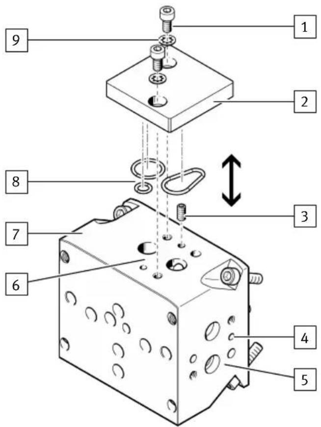
Fig. 28: Moving covering
1 Screw
6 Control valve interface, top
2 Covering
7 Flange module for safety functions VABP
3 Threaded pin
8 O-rings
4 Hole: threaded pin
9 Toothed disc
5 Control valve interface, side
Moving covering
- Loosen the screws of the covering and remove it.
- Unscrew the threaded pin and screw it into the threaded pin hole at the unused interface up to the stop.
- Check that the O-rings on the covering are seated correctly.
- Place the covering on the unused interface in the correct position.
- Slide the two toothed discs onto the two retaining screws to ensure electrical conductivity after assembly.
- Position the retaining screws with toothed disc and tighten evenly.
Tightening torque: 3.5 Nm ± 15%
Mounting control valve
- Check that the seal on the control valve is seated correctly.
- Mount the control valve at the control valve interface on the flange module for safety functions VABP → Assembly instructions for control valve.
5.3.3.2 VABP-C13-100HFT1-F90-VDE1E (hardware fault tolerance 1)
i
The positions of the control valves are specified according to the interfaces. If an interface with mounted covering is used, the covering must be removed.
- Check that the seal on the control valves is seated correctly.
- Mount the control valves at the control valve interface on the flange module for safety functions VABP → Assembly instructions for control valve.
5.3.3.3 VABP-C13-100HFT0-F90-VDE1
- Check that the seal on the control valves is seated correctly.
- Mount the control valve at the control valve interface on the flange module for safety functions VABP → Assembly instructions for control valve.
- Establish a connection from the input supply port of the connecting plate VABP-C13-100HFT0-F90-VDE1 to the input supply port of the solenoid valve VOFC or third-party valve.
5.3.4 Mounting adapter kit VABA
The adapter kit forms the interface for the air connection between the valve terminal VTOP and the positioner.

Fig. 29: Mounting adapter kit
1 Screw
3 Adapter kit
2 Toothed disc
4 Seals
- Check that the seals on the adapter kit are correctly seated.
Assembly
- Place the adapter kit in the correct position on the adapter plate VABA.
- Slide the two toothed discs onto the two retaining screws to ensure electrical conductivity after assembly.
- Screw in the retaining screws with toothed disc and tighten evenly. Tightening torque: 5 Nm ± 10%.
5.3.5 Install the VAME mounting kit
The valve terminal VTOP can be attached to an external mounting plate by mounting the mounting kit VAME on the adapter plate VABA and the end plate VABE.

Fig. 30: Mounting kit VAME
1 Mounting kit VAME-C13-K
2 Toothed disc
3 Screw
4 Adapter plate VABA-C13-100-...-F90-G12-G14
- Place the mounting kit VAME in the correct position on the adapter plate VABA-C13-100-...-F90-G12-G14 and on the end plate VABE.
- Slide the two toothed discs onto the two retaining screws to ensure electrical conductivity after assembly.
- Screw in the retaining screws with toothed disc and tighten evenly. Tightening torque: 15 Nm ± 20%.
6 Installation
6.1 Installation, pneumatic
- Select suitable fittings and silencers → www.festo.com/catalogue.
- Screw the fittings and silencers into the corresponding pneumatic connections. Observe the tightening torque.
- Seal the unused pneumatic ports. Observe the tightening torque.
- Connect the compressed air lines to the fittings.
6.2 Earthing
Connect the earth terminal to the earth terminal with low impedance at the adapter plate.
7 Commissioning
Commissioning, general
i
When using third-party products, observe the documentation of the third-party products.
- Slowly pressurise the valve terminal VTOP.
-
Check the function and the effective direction.
If necessary, change the effective direction 11.2 Reversing effective direction. -
Check the safety engineering reaction time with the selected control valves.
Commissioning volume booster VOGM
Adjusting the volume boost 8.2 Adjusting volume boost
- Before initialisation, fully close the flow control screw on the volume booster VOGM.
- Open the flow control screw a quarter turn.
- Perform the first pass of initialisation.
- Check the position and the control behaviour.
- If the position is not approached correctly, open the flow control screw step by step and repeat the initialisation accordingly.
Commissioning of fail safe module VOGI
- Pressurise the supply air port (1) on the fail safe module VOGI with compressed air. Operating pressure 12.5 Fail safe module VOGI
8 Operation
8.1 Setting the output pressure
The output pressure of the filter regulator PCRI is adjusted with the rotary knob. The rotary knob must not be removed.
- Pull the rotary knob upwards.
The rotary knob is unlocked.
-
Screw down the rotary knob fully anti-clockwise (-).
-
Slowly pressurise the valve terminal VTOP.
-
Turn the rotary knob clockwise (+) until the desired output pressure is reached (1 bar/revolution).
Comply with the pressure regulation range 12 Technical data, 12 Technical data.
- Press the rotary knob down.
The rotary knob is locked.
8.2 Adjusting volume boost
The volume boost or response sensitivity of the compressed air flow rate specified by the positioner is adjusted separately for duct 2 or duct 4 at the volume booster VOGM by a flow control screw.
Initialisation of the volume booster VOGM → 7 Commissioning.
- Unscrew the blanking plug.
The flow control screw is accessible.
- Use a suitable slotted screwdriver to adjust the volume boost or sensitivity with the flow control screw.
Observe the ratio of compressed air flow rate to flow control valve setting → Fig. 32.
-Increase: turn the flow control screw clockwise (+).
- Reduce: turn the flow control screw anti-clockwise (-).
- Screw the blanking plug back in.
9 Maintenance
9.1 Changing filter
The filter on the filter regulator PCRI must be replaced when the flow rate is reduced regardless of the unchanged pressure setting.
- Switch off compressed air supply.
- Unscrew and remove the filter covering with a suitable tool.
- Replace the filter cartridge.
- Check that the seal is seated correctly on the filter covering.
- Replace the filter covering and tighten it. Tightening torque: 20 Nm ± 10%
9.2 Cleaning
Clean the product with a non-abrasive cleaning agent.
10 Fault clearance
| Malfunction Possible cause Remedy | ||
| Low compressed air flow rate Restriction in the compressed air line | - Check compressed air line | |
| Filter cartridge dirty | ||
| Pressure increases above the set working pressure | Valve disc defective at the sealing seat | - Replace the filter regulator PCRI |
| Continuous audible blowing noise at rotary knob | Valve seat damaged | - Replace the filter regulator PCRI |
| Pneumatic drive does not move in the desired direction | Cable of the displacement encoder incorrectly connected to the positioner or the pneumatic drive | - Correct the connection on the positioner or on the pneumatic drive |
| Effective direction reversed | - Reverse the reversing plate in the end plate VABA | |
| Pneumatic drive does not move to the desired end position in the event of a compressed air failure | Supply air port (1) on fail safe module VOGI not connected or operating pressure too low | - Check supply air port (1) on fail safe module VOGI |
| Effective direction reversed | - Reverse the reversing plate in the end plate VABE | |
| Pneumatic drive cannot hold intermediate position | Air flow rate at the volume booster VOGM too low | - Increase air flow rate |
| Mechanical defects in the compressed air lines and functional elements, e.g. corrosion or leakage | Excessive condensate formation | - Install condensate drain or water separator, e.g. PWEA or MS-LWS |
Tab. 9: Fault clearance
11 Modification
11.1 Converting valve terminal VTOP
The valve terminal VTOP is converted in the reverse order of mounting 5 Assembly. The installation rules must be observed 5.1.1 Rules for set-up.
11.2 Reversing effective direction

1 End plate VABA
2 Reversing plate
3 Screw
4 Split washer
5 Seal
Fig. 31: Reversing effective direction
- Unscrew the screws of the end plate VABA.
- Remove the end plate VABA.
- Unscrew the screw of the reversing plate.
- Remove the reversing plate from the end plate VABA.
- Check that the seals on the reversing plate are seated correctly.
- Replace the reversing plate in the end plate VABA.
- Attach the split washer to the screw of the reversing plate.
- Tighten the screw of the reversing plate. Tightening torque: 0.9 Nm ± 10%
- Assemble the end plate VABA with the module in the correct position.
- Apply the screws of the end plate VABA and tighten evenly. Tightening torque: 10 Nm ± 20%
12 Technical data
12.1 Valve terminal VTOP
VTOP
| Certificates, declaration of conformity | → www.festo.com/sp | |
| Design Modular valve terminal | ||
| Mounting position Any | ||
| Ambient temperature [°C] -40 ... (module-dependent) | +80 | |
| Storage temperature [°C] -40 ... (module-dependent) | +80 | |
| Operating medium Compressed air to ISO 8573-1:2010 | ||
| Inert gases | ||
| Operating pressure [MPa] 0 ... (module-dependent) | 0.9 | |
| [bar] 0 ... 9 | ||
| [psi] 0 ... 130.5 | ||
| Corrosion protection CRC3 | ||
| Vibration resistance in accordance with DIN EN 60068-2-6 | Severity level 1 | |
| Shock resistance in accordance with DIN EN 60068-2-27 | Severity level 1 | |
| Continuous shock resist-ance in accordance with DIN EN 60068-2-29 | Severity level 1 | |
Tab. 10: Technical data – Valve terminal VTOP
12.2 Adapter plate VABA
| VABA-C13-100-...-F90 -G12 -G12-G14 | ||
| Certificates, declaration of conformity | → www.festo.com/sp | |
| Design Sub-base valve | ||
| Ambient temperature [°C] -40 ... +80 | ||
| Storage temperature [°C] -40 ... +80 | ||
| Temperature of medium [°C] -40 ... +80 | ||
| Operating medium Compressed air to ISO | 8573-1:2010 [7:7:-] | |
| Inert gases | ||
| Information on the operating medium | Lubricated operation not possible | |
| Operating pressure [MPa] 0 ... 0.9 | ||
| [bar] 0 ... | 9 | |
| [psi] 0 ... | 130.5 | |
| Pneumatic port 1 G 1/2 | ||
| Pneumatic port 2 - G 1/4 | ||
| Pneumatic port 3 G 1/2 | ||
| Pneumatic port 4 - G 1/4 | ||
Tab. 11: Technical data – Adapter plate VABA
12.3 Volume booster VOGM
| VOGM-FD100 -...- M-F90 -M33E -T33H | ||
| Certificates, declaration of conformity | → www.festo.com/sp | |
| Design Sub-base valve | ||
| Method of operation Single-acting Double-acting | ||
| Ambient temperature [°C] -40 ... +80 | ||
| Storage temperature [°C] -40 ... +80 | ||
| Temperature of medium [°C] -40 ... +80 | ||
| Operating medium Compressed air to ISO 8573-1:2010 [7:7:-] | ||
| Information on the operating medium | Lubricated operation not possible | |
| Operating pressure [MPa] 0.14 ... 0.8 | ||
| [bar] 1.4 ... 8 | ||
| [psi] | 20.3 ... 116 | |
| Standard nominal flow rate [l/min] | 1240 | |
Tab. 12: Technical data – Volume booster VOGM
Ratio of air flow rate to flow control valve setting

line
| r[n] | Q[l/min] | | ---- | -------- | | 0 | 0 | | 1 | 100 | | 2 | 150 | | 3 | 200 | | 4 | 250 | | 5 | 275 | | 6 | 290 | | 7 | 300 | | 8 | 310 |Fig. 32: Ratio of air flow rate to flow control valve setting
12.4 Filter regulator PCRI
| PCRI-100-F90-12-...-T3 -C -E | ||
| Certificates, declaration of conformity | → www.festo.com/sp | |
| Design Sub-base valve | ||
| Grade of filtration [μm] 5 40 | ||
| Ambient temperature [°C] -40 ... +80 | ||
| Storage temperature [°C] -40 ... +80 | ||
| Temperature of medium [°C] -40 ... +80 | ||
| Connection for pressure gauge | G 1/4 | |
| Operating medium Compressed air to ISO | 8573-1:2010 [-:7:-] | |
| Inert gases | ||
| Information on the operating medium | Lubricated operation not possible | |
| Operating pressure [MPa] 0.1 ... 0.9 | ||
| [bar] 1 ... | 9 | |
| [psi] 14.5 | ... 130.5 | |
| Air purity class at the output | Compressed air in accordance with ISO 8573-1:2010 [6:7:-] | Compressed air in accordance with ISO 8573-1:2010 [7:7:-] |
| Pressure regulation range [MPa] 0.05 ... 0.8 | ||
| [bar] 0.5 ... 8 | ||
| [psi] 7.25 ... 116 | ||
| Standard nominal flow rate [l/min] | 1400 | |
| Flow rate [l/min] | Dependent on the set output pressure | |
Tab. 13: Technical data – Filter regulator PCRI
Flow rate of filter regulator PCRI

line
| Q [l/min] | p [MPa] | | --------- | ------- | | 0 | 0.8 | | 500 | 0.7 | | 1000 | 0.6 | | 1500 | 0.5 | | 2000 | 0.4 |Fig. 33: Flow rate of filter regulator PCRI
12.5 Fail safe module VOGI
VOGI-F100FS-T32H-M-F90
| Certificates, declaration of conformity | → www.festo.com/sp | |
| Design Sub-base valve | ||
| Method of operation Double-acting | ||
| Ambient temperature [°C]–20 ... +80 | ||
| Storage temperature [°C]–20 ... +80 | ||
| Temperature of medium [°C]–20 ... +80 | ||
| Operating medium Compressed air to ISO 8573-1:2010 [7:7:-] | ||
| Inert gases | ||
| Information on the operating medium | Lubricated operation not possible | |
| Operating pressure [MPa] 0.33 ... 0.8 | ||
| [bar] 3.3 ... 8 | ||
| [psi] 43.5 ... 116 | ||
| Pneumatic port 1 G 1/2 | ||
| Standard nominal flow rate [l/min] | 1093 | |
Tab. 14: Technical data – fail safe module VOGI
12.6 Flange module for safety functions VABP
| VABP-C13-...-F90-VDE1(E) -100HFT0 -100HFT1 | ||
| Certificates, declaration of conformity | → www.festo.com/sp | |
| Design Flange module | ||
| Architectures for safe venting HFT 0, for | 1oo1 HFT 1, for 1oo2 | |
| Ambient temperature [°C] -40 ... +80 | ||
| Storage temperature [°C] -40 ... +80 | ||
| Temperature of medium [°C] -40 ... +80 | ||
| Operating medium Compressed air to ISO | 8573-1:2010 [7:7:-] | |
| Inert gases | ||
| Information on the operating medium | Lubricated operation not possible | |
| Operating pressure [MPa] 0 ... 0.8 | ||
| [bar] 0 ... | 8 | |
| [psi] 0 ... | 116 | |
| Standard nominal flow rate [l/min] | Dependent on the installed control valve | |
Tab. 15: Technical data – Flange module for safety functions VABP
12.7 End plate VABE
| VABE-C13-100-F90-DU | |
| Certificates, declaration of conformity | → www.festo.com/sp |
| Design End plate with reversing plate | |
| Ambient temperature [°C] -40 ... +80 | |
| Storage temperature [°C] -40 ... +80 | |
| Temperature of medium [°C] -40 ... +80 | |
| Operating medium Compressed air to ISO 8573-1:2010 [7:7:-] | |
| Information on the operating medium | Lubricated operation not possible |
| Operating pressure [MPa] 0 ... 0.8 | |
| [bar] 0 ... | 8 |
| [psi] 0 ... | 116 |
Tab. 16: Technical data – End plate VABE
12.8 Adapter kit VABA
VABA-C13-G14
| Certificates, declaration of conformity | → www.festo.com/sp |
| Design Flange module | |
| Ambient temperature [°C] -40 ... +80 | |
| Storage temperature [°C] -40 ... +80 | |
| Temperature of medium [°C] -40 ... +80 | |
| Operating medium Compressed air to ISO | 8573-1:2010 [7:7:-] |
| Inert gases | |
| Information on the operating medium | Lubricated operation not possible |
| Operating pressure [MPa] 0 ... 0.8 | |
| [bar] 0 ... 8 | |
| [psi] 0 ... 116 | |
| Pneumatic port 1 G 1/4 | |
| Pneumatic port 2 G 1/4 | |
| Pneumatic port 4 G 1/4 |
Tab. 17: Technical data – Adapter kit VABA
Copyright:
Festo SE & Co. KG
Ruiter Straße 82
73734 Esslingen
Germany
Phone:
+49 711 347-0
- FESTO
- Table of contents
- About this document.... 5
- Safety....6
- Additional information....7
- Product overview.... 8
- Assembly....23
- Installation.... 29
- Commissioning....29
- Operation.... 30
- Maintenance.... 30
- Fault clearance.... 31
- Modification.... 31
- Technical data....33
- About this document
- Applicable documents
- Product designation
- Product labelling
- Specified standards
- Safety
- Safety instructions
- Intended use
- Permissible components
- Training of qualified personnel
- Additional information
- Product overview
- Structure
- Valve terminal VTOP
- Adapter plate VABA
- Adapter plate VABA-C13-100-1-F90-G12
- Adapter plate VABA-C13-100-2-F90-G12
- Adapter plate VABA-C13-100-1-F90-G12-G14
- Adapter plate VABA-C13-100-2-F90-G12-G14
- Volume booster VOGM
- Filter regulator PCRI
- Fail safe module VOGI
- Flange module for safety functions VABP
- VABP-C13-100HFT0-F90-VDE1E
- Product overview
- End plate VABE
- Adapter kit VABA
- Mounting kit VAME
- Module overview
- Function
- Assembly
- Assembling
- Rules for set-up
- Attachment
- Attaching valve terminal VTOP
- Attaching positioner
- Mounting accessories
- Mounting pressure gauge
- Removing pressure gauge
- Mounting control valve
- VABP-C13-100HFT0-F90-VDE1E (hardware fault tolerance 0)
- Assembly
- Moving covering
- Mounting control valve
- VABP-C13-100HFT1-F90-VDE1E (hardware fault tolerance 1)
- VABP-C13-100HFT0-F90-VDE1
- Mounting adapter kit VABA
- Install the VAME mounting kit
- Installation
- Installation, pneumatic
- Earthing
- Commissioning
- Commissioning, general
- Commissioning volume booster VOGM
- Commissioning of fail safe module VOGI
- Operation
- Setting the output pressure
- Adjusting volume boost
- Maintenance
- Changing filter
- Cleaning
- Modification
- Converting valve terminal VTOP
- Reversing effective direction
- Technical data
- Valve terminal VTOP
- Fail safe module VOGI
- Adapter kit VABA
Brand : Festo
Model : VTOP
Category : Industrial valve