DGSC-6-10-P-P - Drill Festo - Free user manual and instructions
Find the device manual for free DGSC-6-10-P-P Festo in PDF.


| Product Type | Non-rotating single-piston drive with bearing guide |
| Design | Double-acting drive with Scotch yoke system and ball bearing cage guide |
| Mounting Position | Any |
| Cushioning | Elastic cushioning ring on both sides |
| Operating Medium | Compressed air to ISO 8573-1:2010 [7:4:4] |
| Operating Pressure | 0.1 ... 0.6 MPa (1.0 ... 6.0 bar, 14.5 ... 87.0 psi) |
| Ambient Temperature | 10 ... 50 °C |
| Repetition Accuracy | < 0.2 mm |
| Product Weight (DGSC-6-10-P-P) | 52 g |
| Moving Mass | 17 g |
| Maximum Payload | 30 g |
| Stroke Compensation via Spring | -2.5 ± 1 mm |
| Theoretical Force at 0.6 MPa (Extending) | 17.0 N |
| Theoretical Force at 0.6 MPa (Retracting) | 12.7 N |
| Materials (Piston rod, Housing) | High-alloy stainless steel |
| Materials (Seals) | Nitrile rubber |
| Pneumatic Port Threads | M3 and M5 |
| Intended Use | Space-saving transport of masses; slide operating mode |
| Maintenance - Cleaning | Clean with soft cloth and suitable cleaning agents |
| Maintenance - Lubrication | Initially lubricated; re-grease guide after 5 million cycles |
| Safety | Switch off compressed air supply before working; repair only by Festo |
Frequently Asked Questions - DGSC-6-10-P-P Festo
User questions about DGSC-6-10-P-P Festo
0 question about this device. Answer the ones you know or ask your own.
Ask a new question about this device
Download the instructions for your Drill in PDF format for free! Find your manual DGSC-6-10-P-P - Festo and take your electronic device back in hand. On this page are published all the documents necessary for the use of your device. DGSC-6-10-P-P by Festo.
USER MANUAL DGSC-6-10-P-P Festo
natural_image
Technical line drawing of two mechanical bracket components (no text or symbols)Operating instructions
8168642
2022-02b
[8168644]

8168642
Translation of the original instructions
© 2022 all rights reserved to Festo SE & Co. KG
1 Applicable Documents
i
All available documents for the product→ www.festo.com/sp.
2 Safety
2.1 Safety instructions
- Take into account the ambient conditions at the location of use.
-Only use the product in its original condition without unauthorised modifications. - Observe the identifications on the product.
-Store the product in a cool, dry environment protected from UV and corrosion. Keep storage times short. - Before working on the product, switch off the compressed air supply and lock it to prevent it from being switched on again.
- Have the product repaired by the Festo repair service only.
-Observe the tightening torques. Unless otherwise specified, the tolerance is ± 20% .
2.2 Intended use
The product is intended for the space-saving transport of masses. The product is approved for slide operating mode.
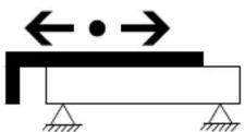
Fig.1
2.3 Training of qualified personnel
Work on the product may only be carried out by qualified personnel who can evaluate the work and detect dangers. The qualified personnel have skills and experience in dealing with pneumatic (open-loop) control technology.
3 Additional information
- Contact the regional Festo contact if you have technical problems → www.festo.com.
- Accessories and spare parts → www.festo.com/catalogue.
4 Product overview
4.1 Function
The product is a non-rotating single-piston drive with bearing guide. The slide is moved back and forth by alternate pressurisation of the supply ports. In the retracted end position, the slide is braked by elastic cushioning rings with a mechanical fixed stop. In the extended end position, an integrated spring serves as stroke compensation to avoid high forces on the workpiece during handling.
4.2 Product design
DGSC-6-10-PL
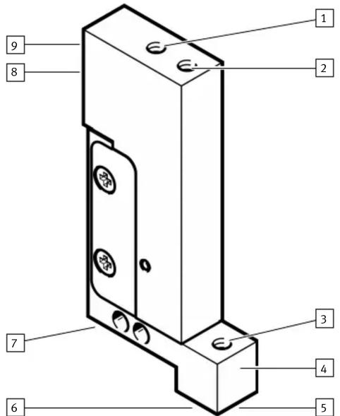
Fig. 2: Product design DGSC-6-10-PL
1 Supply port retracting
2 Supply port extending
3 Vacuum port
4 Slide
5 Centre hole 1.5 mm according to DIN 6325, 2x
6 M5 thread for suction cup with connection or mounting
7 M3 thread, e.g. for tubing holder
8 M3 thread for mounting, 2x
9 Centre hole 2 mm according to DIN 6325, 2x
DGSC-6-10-PP
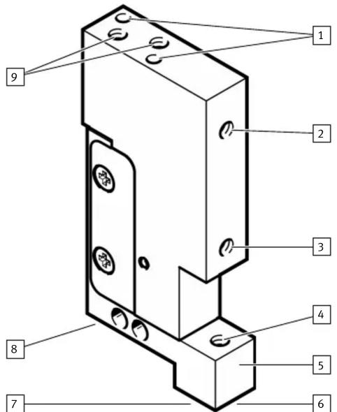
Fig. 3: Product design DGSC-6-10-P-P
1 Centre hole 2 mm according to DIN 6325
2 Supply port extending
3 Supply port retracting
4 Vacuum port
5 Slide
6 Centre hole 1.5 mm according to DIN 6325
7 M5 thread for suction cup with connection or mounting
8 M3 thread, e.g. for tubing holder
9 M3 thread for mounting
5 Transport
NOTICE
Unexpected and unbraked movement of components
- Secure moving components for transport.
i
The product can be attached to the housing or the slide.
- Use suitable fastening material depending on the type of mounting.
- Observe the maximum screw-in length of the screws.
- Mount the product according to the type of mounting.
- Maintain the maximum tightening torques.
• Mount the product without tension.
Mounting on the housing
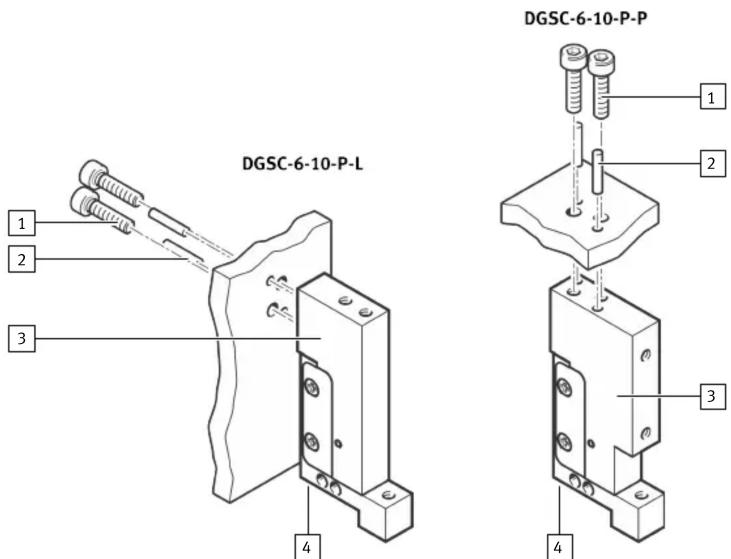
Fig. 4: Mounting on the housing
1 M3 screw according to DIN 912, 2x
2 Cylindrical pin 2 mm according to DIN 6325, 2x
3 Housing
4 M3 thread, e.g. for tubing holder
Screw-in length and tightening torque
| Position 1 4 | ||
| Max. screw-in length [mm] 4.5 4.0 | ||
| Max. tightening torque [Nm] 1.2 1.2 |
Tab. 1: Screw-in length and tightening torque
Mounting on slide
i
- Support the slide from the opposite side when pressing in the cylindrical pins.
- When tightening the screw on the slide, counterhold with an 8 mm open-ended spanner.
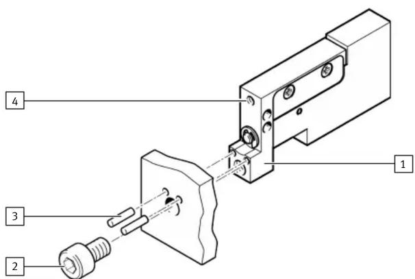
Fig. 5: Mounting on the slide, DGSC-6-10-PP as an example
1 Slide
2 M5 screw according to DIN 912, 2x
3 Cylindrical pin 1.5 mm according to DIN 6325, 2x
4 M3 thread, e.g. for tubing holder
Screw-in length and tightening torque
| Position 3 4 | ||
| Max. screw-in length [mm] 4.0 4.0 | ||
| Max. tightening torque [Nm] 5.9 1.2 |
Tab. 2: Screw-in length and tightening torque
7 Installation
- Screw suitable fittings or accessories into the pneumatic ports. Maintain the maximum tightening torques.
- Connect tubing to the pneumatic ports.
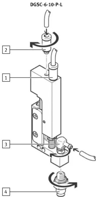
Fig. 6: Installation
1 Supply port extending
2 Supply port retracting
1 Supply port extending
2 Supply port retracting
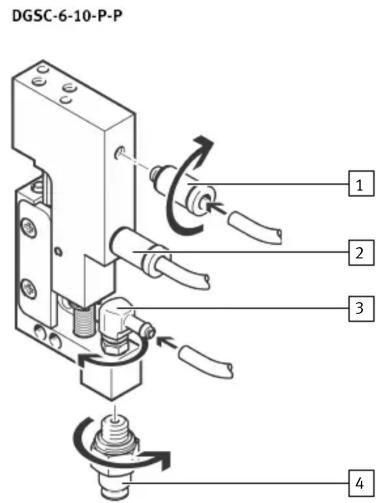
3 Vacuum port
4 Suction cup with connection
Connection thread and tightening torques
| Position 1, 2, 3 4 | ||
| Connecting thread | M3 M5 | |
| Max. tightening torque [Nm] 1.2 5.9 |
Tab. 3: Connection thread and tightening torques
8 Commissioning
• Pressurise the product slowly.
9 Maintenance
9.1 Cleaning
- Clean the product as required with a clean soft cloth and suitable cleaning agents compatible to the material.
9.2 Lubrication
i
The product is initially lubricated.
Recommendation:
- Regrease the guide after 5 million cycles.
10 Fault clearance
| Fault description | Cause | Remedy |
| The slide moves unevenly. The one-way flow control valves are not installed correctly. | Control the exhaust air flow. | |
| The slide is in initial position despite pressurisation. | The tubing is faulty. | Check the tubing. |
| The slide speed is too low. | The air volume is insufficient. | Increase the connection cross-sections. |
| Check the flow control valve setting. | ||
| Connect a volume upstream. | ||
| The slide stops in the end position without cushioning. | The speed is too high. | Reduce the speed. |
| The cushioning is too low. Reduce the speed. | ||
| Check the cushioning rings and replace if necessary. | ||
| The air cushion is not present. | Pressurise both supply ports simultaneously, then exhaust one side. | |
| The payload is too high. | Reduce the payload. | |
Tab. 4: Fault clearance
11 Modification
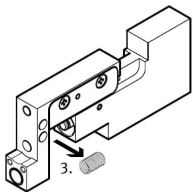
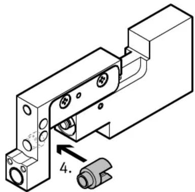
In its delivery status the product is equipped with a spring for stroke compensation. Replacing the spring with the enclosed blue spacer allows the stroke compensation of the extended end position to be suppressed and converted to a fixed stop.
- Shut off the compressed air supply and lock to prevent reactivation.
Conversion to fixed stop
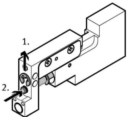
Fig.7
- Remove the shaft circlip.
- Push in the shaft.
natural_image
Technical line drawing of a mechanical assembly with bolt holes and a threaded component (no text or symbols)- Remove the spring.
natural_image
Technical line drawing of a mechanical assembly with mounting holes and a numbered component (no text or symbols)- Insert the enclosed blue spacer in the correct position.
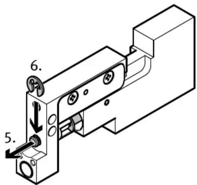
- Slide out the shaft.
- Install the shaft circlip.
12 Technical data
| DGSC-6-10-P-... -L -P | |||
| Design Double-acting drive with Scotch | yoke system and ballbearing cage guide | ||
| Mounting position Any | |||
| Cushioning Elastic cushioning ring on both sides | |||
| Operating medium Compressed air to ISO 8573-1:2010 [7:4:4] | |||
| Information on the operating medium | lubricated operation possible, in which case lubricated operation will always be required | ||
| Operating pressure [MPa] 0.1 ... 0.6 | |||
| [bar] 1.0 ... 6.0 | |||
| [psi] 14 ... 87.0 | |||
| Ambient temperature [°C] 10 ... 50 | |||
| Repetition accuracy [mm] | <0.2 | ||
| Product weight [g] | 42 | 52 | |
| Moving mass [g] | 17 | ||
| Max. payload [g] | 30 | ||
| Length of stroke compensation via spring [mm] | -2.5 ± 1 | ||
| Max. forces and torques | → www.festo.com/catalogue | ||
| Theoretical force at 0.6 MPa (6 bar, 87 psi) | |||
| Extending [N] | 17.0 | ||
| Retracting [N] | 12.7 | ||
| Materials | |||
| Piston rod, housing | High-alloy stainless steel | ||
| Seals | Nitrile rubber | ||
Tab. 5: Technical data
- Applicable Documents
- Safety
- Safety instructions
- Intended use
- Training of qualified personnel
- Additional information
- Product overview
- Function
- Product design
- Transport
- NOTICE
- Unexpected and unbraked movement of components
- Mounting on slide
- Installation
- Commissioning
- Maintenance
- Cleaning
- Lubrication
- Modification
Brand : Festo
Model : DGSC-6-10-P-P
Category : Drill